floodlighting poles 6 | floodlighting poles court the court range is commonly used for floodlighting...
TRANSCRIPT

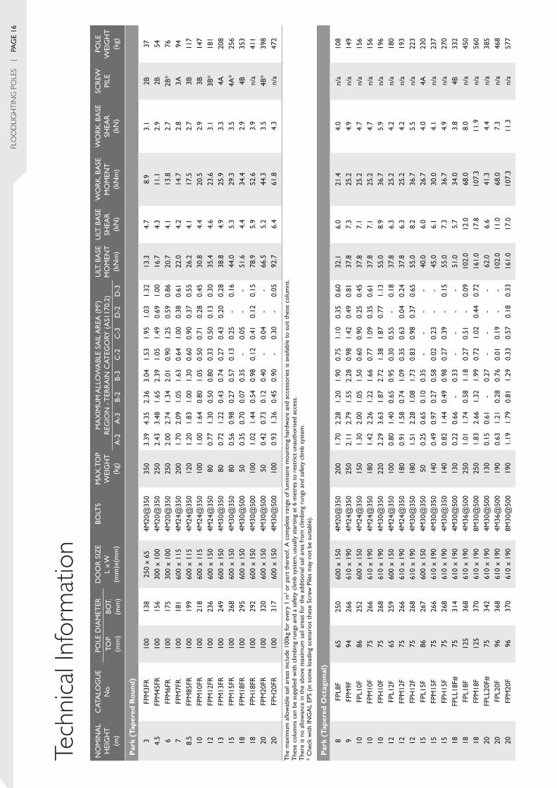
Floodlighting Poles

>> Australia’s leading manufacturer of quality pole products with representation in every state and territory.

INGAL EPS is a division of Industrial Galvanizers Corporation Pty Ltd which is ultimately owned by Valmont Industries Inc. Actively involved in the Australian pole market since 1969, INGAL EPS has strived to continuously lead the industry in research, design, innovation, quality of product and quality of service. Establishing industry benchmarks such as the Seesaw pole, 60km/h and 110km/h Impact Absorbing poles and the largest steel poles ever installed in both Australia and New Zealand.
The company employs around 150 staff and has offices located in every state and territory of Australia and on the North Island of New Zealand. With manufacturing facilities in Brisbane and Perth and full access to three modern facilities in China owned by Valmont Industries Inc, INGAL EPS is well positioned to meet the broad requirements of the pole market. Due to our extensive experience, national coverage, resources and manufacturing capacity we have the ability to provide the most comprehensive product range available.
The INGAL EPS product range includes:
• Street Lighting poles
• Floodlighting poles
• Power poles
• Lowering Systems, for ease of maintenance
• Special Application poles including banner poles, camera poles, traffic signal and communication poles
• Services & Accessories providing individual design, drafting, installation and accessories including foundation materials, adaptors, headframes and cross arms.
With our dedicated design service, material control, quality assured manufacturing processes and after sales service, INGAL EPS has established itself as Australasia’s largest pole supplier. INGAL EPS has over four decades of experience leading the industry in Australia and our ever improving product range and expanded manufacturing resources will continue to ensure we’re at the cutting edge of providing new and innovative solutions to a growing and ever more demanding market.

Standard Mall Poles
Mall Pole

FLooDLIGhTING PoLES | PaGe 5
MallThe simple design component of the Mall range is ideal for carpark, mall and pathway floodlighting. Mall poles are of a circular parallel pipe construction and are best suited for post top luminaires.
options and Accessories• Mall poles are base plate mounted as standard but can be designed for in-ground mounting• The poles are hot dip galvanized and can be powder coated or painted in the colour of your choice• The range is available in circular hollow section (ChS) only• Standard mounting heights are 3m to 6.5m• The standard poles are depicted on this product sheet• Luminaire adaptors• Preassembly• Pre cabling• Installation.
Product Codes For more information, please refer to the Technical Data Sheet.
Mall
3m 3.5m 4.5m 5.5m 6.5m
FMM3F FMM35F FMM45F FMM55F FMM65FFMH3F FMH35F FMH45F FMH55F FMH65F
F=Floodlighting M=Mall M=Medium Duty H=Heavy Duty F=Flange Mounted (Base Plate)
Standard Mall Poles

PaGe 6 | FLooDLIGhTING PoLES
CourtThe Court range is commonly used for floodlighting tennis and basketball courts, schools and carparks. The design of the square parallel tube pole caters for applications where architecturally a square profile is preferred to suit the mounting of rectangular luminaires, such as the shoebox type lighting fixture.
options and Accessories• Court poles are base plate mounted as standard but can be designed for in-ground mounting• The poles are hot dip galvanized and can be powder coated or painted in the colour of your choice• The range is available in square hollow section (ShS) only• Standard mounting heights are 4m to 10m• The standard poles are depicted on this product sheet, however they can be designed for different heights• Luminaire adaptors• Preassembly• Pre cabling• Installation.
Product Codes For more information, please refer to the Technical Data Sheet.
Court
4m 5m 6m 8m 10m
FCl4F FCl5F FCl6F FCl8F FCl10F
FCM4F FCM5F FCM6F FCM8F FCM10F
FCH8F FCH10F
FCX10F
F=Floodlighting C=Court l=light Duty M=Medium Duty H=Heavy Duty X=extra Heavy Duty F=Flange Mounted (Base Plate)
Standard Court Poles

Standard Court Poles
Court Pole

BoulevarD Pole

FLooDLIGhTING PoLES | PaGe 9
BoulevardThe Boulevard range of Floodlighting Poles are the most flexible in terms of design. Ideally suited for medium sized floodlighting requirements such as commercial developments and recreational area applications, the range is available in tapered octagonal and tapered round poles. The range has been designed to allow for greater luminaire control gear space in the base of the pole, in order to accommodate multiple lighting fixtures.
options and Accessories• Boulevard poles are base plate mounted as standard but can be designed for in-ground mounting• The poles are hot dip galvanized and can be powder coated or painted in the colour of your choice• The standard poles are depicted on this product sheet, however they can be designed for different heights• Tapered octagonal Boulevard Poles are available in a Seesaw configuration, refer to the Lowering Systems brochure• Preassembly• Pre cabling• Installation.
Product Codes For more information, please refer to the Technical Data Sheet.
Boulevard (Tapered Octagonal)
3m 3.5m 4.5m 5.5m 6m 7m 8m 8.5m 9m 10m 12m
FBM3F FBM35F FBM45F FBM55F FBM6F FBM7F FBM8F FBM85F FBM9F FBM10F FBM12F
Boulevard (Tapered Round)
3m 4.5m 6m 7m 8.5m 10m 12m 13m 15m
FBM3Fr FBM45Fr FBM6Fr FBM7Fr FBM85Fr FBM10Fr FBM12Fr FBM13Fr FBM15Fr
F=Floodlighting B=Boulevard M=Medium Duty F=Flange Mounted (Base Plate) r=tapered round
tapered round Boulevard Polestapered octagonal Boulevard Poles

PaGe 10 | FLooDLIGhTING PoLES
ParkThe Park range is suitable for large commercial applications such as floodlighting for sporting ovals and golf driving ranges. The design of this range allows for multiple lighting fixtures to be accommodated.
options and Accessories• Park poles are base plate mounted as standard but can be
designed for in-ground mounting• The poles are hot dip galvanized and can be powder coated
or painted in the colour of your choice• The poles are available in tapered round and tapered octagonal• Standard mounting heights are 3m to 20m in tapered round
and 8m to 30m in tapered octagonal• The standard poles are depicted on this product sheet,
however they can be designed for different heights• Tapered octagonal Park Poles are available in a Seesaw
configuration, refer to the Lowering Systems brochure
• Additional access doors• Luminaire Adaptors, Cross Arms, headframes and Lightning
Protection Rods• Climbing rungs can be attached to the pole commencing at 6m• Lad Saf® system commencing at 6m• Lamping platform• Preassembly• Pre cabling• Installation.
Product Codes For more information, please refer to the Technical Data Sheet.
Park (Tapered Octagonal)
8m 9m 10m 12m 15m 18m 20m 22m 25m 27m 30m
FPl8F FPM9F FPl10F FPl12F FPl15F FPll18F FPll20F FPl22F FPll25F FPll27F FPll30FFPM10F FPM12F FPM15F FPl18F FPl20F FPl25F FPl27F FPl30FFPH10F FPH12F FPH15F FPM18F FPM20F FPM25F FPM27F FPM30F
FPH20F
Park (Tapered Round)
3m 4.5m 6m 7m 8.5m 10m 12m 13m 15m 18m 20m
FPM3Fr FPM45Fr FPM6Fr FPM7Fr FPM85Fr FPM10Fr FPM12Fr FPM13Fr FPM15Fr FPM18Fr FPM20FrFPH18Fr FPH20Fr
F=Floodlighting P=Park ll= extra light Duty l=light Duty M=Medium Duty H=Heavy Duty F=Flange Mounted (Base Plate) r=tapered round
Standard tapered octagonal Park Poles Standard tapered round Park Poles

Park Pole

traCk Pole

FLooDLIGhTING PoLES | PaGe 13
TrackThe Track range is most suited for stadium floodlighting where optimum lighting specifications need to be achieved. Designed with 16 sides for greater strength, the poles in this range can accommodate larger than normal sail areas to attain your lighting requirements.
options and Accessories• Track poles are base plate mounted as standard but can be designed for in-ground mounting• The poles are hot dip galvanized and can be powder coated or painted in the colour of your choice• The poles are available in tapered 16 sided• Standard mounting heights are 6m to 30m• The standard poles are depicted on this product sheet, however they can be designed for different heights• Additional access doors• Luminaire Adaptors, Cross Arms, headframes and Lightning Protection Rods• Climbing rungs can be attached to the pole commencing at 6m• Lad Saf® system commencing at 6m• Lamping platform• Preassembly• Pre cabling• Installation.
Product Codes For more information, please refer to the Technical Data Sheet.
Track
6m 8m 10m 12m 15m 20m 25m 27m 30m
FtM6F FtM8F FtM10F FtM12F Ftl15F Ftl20F FtM25F FtM27F FtM30FFtM15F FtM20F FtH25F FtH27F FtH30F
FtH20F
F=Floodlighting t=track l=light Duty M=Medium Duty H=Heavy Duty F=Flange Mounted (Base Plate)
Standard track Poleslamping Platform

FLo
oD
LIG
hTI
NG
Po
LES
| Pa
Ge
14
Tech
nica
l Inf
orm
atio
nN
oM
iNa
l H
eiG
Ht
(m
)
Cat
alo
Gu
e
No.
Pole
Dia
Met
erD
oo
r S
ize
l x
W
(mm
)x(m
m)
Bolt
SM
aX
. to
P W
eiG
Ht
(k
g)
Ma
XiM
uM
all
oW
aBl
e Sa
il a
rea
(M
2 )
reG
ioN
- t
err
aiN
Cat
eGo
ry (
aS1
170.
2)u
lt. B
aSe
M
oM
eNt
(k
Nm
)
ult
. Ba
Se
SHea
r
(kN
)
Wo
rk
. Ba
Se
Mo
MeN
t
(kN
m)
Wo
rk
. Ba
Se
SHea
r
(kN
)
SCr
eW
Pile
Pole
W
eiG
Ht
(k
g)to
P (m
m)
Bot.
(m
m)
a-2
a-3
B-2
B-3
C-2
C-3
D-2
D-3
Mal
l 3FM
M3F
7676
100
x 40
4M20
@23
380
0.80
1.10
0.60
0.80
0.40
0.55
0.25
0.30
3.8
1.5
2.5
1.0
2a26
3FM
H3F
9090
100
x 50
4M20
@23
390
1.20
1.60
0.80
1.10
0.55
0.80
0.30
0.50
6.0
2.1
4.0
1.4
2a33
3.5
FMM
35F
7676
100
x 40
4M20
@23
375
0.65
0.85
0.50
0.60
0.25
0.40
0.15
0.20
3.8
1.2
2.5
0.8
2a30
3.5
FMH
35F
9090
100
x 50
4M20
@23
385
1.00
1.40
0.70
0.90
0.40
0.60
0.25
0.40
6.0
1.9
4.0
1.3
2a38
4.5
FMM
45F
7676
100
x 40
4M20
@23
350
0.40
0.60
0.25
0.40
0.10
0.20
-0.
103.
81.
22.
50.
82a
374.
5FM
H45
F90
9010
0 x
504M
20@
233
750.
600.
900.
400.
600.
200.
400.
130.
206.
01.
64.
01.
12a
475.
5FM
M55
F76
7610
0 x
404M
20@
233
300.
200.
400.
100.
25-
0.10
--
3.8
1.0
2.5
0.7
2a43
5.5
FMH
55F
9090
100
x 50
4M20
@23
365
0.35
0.65
0.20
0.40
0.10
0.20
-0.
106.
01.
54.
01.
02a
556.
5FM
M65
F76
7610
0 x
404M
20@
233
200.
090.
20-
0.10
--
--
3.8
1.0
2.5
0.7
2a50
6.5
FMH
65F
9090
100
x 50
4M20
@23
340
0.20
0.40
0.10
0.25
-0.
10-
-6.
01.
34.
00.
92a
64
the
max
imum
allo
wab
le s
ail a
reas
incl
ude
100k
g fo
r ev
ery
1 m
2 or
part
the
reof
. a c
ompl
ete
rang
e of
lum
inai
re m
ount
ing
hard
war
e an
d ac
cess
orie
s is
ava
ilabl
e to
sui
t th
ese
colu
mns
. t
hese
col
umns
are
not
rec
omm
ende
d to
be
supp
lied
with
clim
bing
run
gs.
Co
urt
4FC
l4F
100
100
210
x 60
4M20
@23
311
01.
301.
900.
901.
400.
400.
700.
300.
4010
.03.
06.
70.
62a
834
FCM
4F12
512
521
0 x
604M
20@
233
130
1.40
2.00
1.00
1.50
0.60
0.85
0.40
0.60
12.0
3.2
8.0
0.6
2a99
5FC
l5F
100
100
210
x 60
4M20
@23
310
00.
801.
300.
500.
900.
100.
40-
0.20
10.0
3.0
6.7
0.6
2a95
5FC
M5F
125
125
210
x 60
4M20
@23
312
00.
901.
500.
551.
050.
300.
550.
200.
3512
.03.
68.
00.
72a
118
6FC
l6F
100
100
210
x 60
4M20
@23
370
0.40
0.90
0.20
0.50
-0.
10-
-10
.03.
06.
70.
62a
110
6FC
M6F
125
125
210
x 60
4M20
@23
311
00.
601.
200.
300.
80-
0.20
--
18.3
3.6
12.2
0.7
2a*
136
8FC
l8F
100
100
210
x 60
4M20
@23
330
0.14
0.35
-0.
20-
--
-10
.03.
26.
70.
62a
141
8FC
M8F
125
125
210
x 60
4M20
@35
075
0.55
1.00
0.30
0.70
0.09
0.25
--
21.0
4.0
14.0
0.8
2B*
174
8FC
H8F
150
150
210
x 60
4M24
@35
012
01.
101.
800.
701.
250.
300.
60-
0.20
39.5
6.5
26.3
1.3
3B*
206
10FC
l10F
100
100
210
x 60
4M20
@23
315
-0.
15-
--
--
-10
.03.
26.
70.
62a
171
10FC
M10
F12
512
521
0 x
604M
20@
350
600.
200.
70-
0.30
--
--
21.0
4.0
14.0
0.8
2B*
212
10FC
H10
F15
015
021
0 x
604M
24@
350
100
0.45
1.30
0.20
0.60
-0.
15-
-39
.56.
226
.31.
23B
*25
210
FCX
10F
150
150
210
x 60
4M30
@35
010
00.
701.
700.
400.
85-
0.30
--
47.4
8.9
31.6
1.8
4a*
302
the
max
imum
allo
wab
le s
ail a
reas
incl
ude
100k
g fo
r ev
ery
1 m
2 or
part
the
reof
. a c
ompl
ete
rang
e of
lum
inai
re m
ount
ing
hard
war
e an
d ac
cess
orie
s is
ava
ilabl
e to
sui
t th
ese
colu
mns
. t
hese
col
umns
are
not
rec
omm
ende
d to
be
supp
lied
with
clim
bing
run
gs.
* C
heck
with
iNG
al
ePS
(in s
ome
load
ing
scen
ario
s th
ese
Scre
w P
iles
may
not
be
suita
ble)
.

No
MiN
al
Hei
GH
t
(m)
Cat
alo
Gu
e
No.
Pole
Dia
Met
erD
oo
r S
ize
l x
W
(mm
)x(m
m)
Bolt
SM
aX
. to
P W
eiG
Ht
(k
g)
Ma
XiM
uM
all
oW
aBl
e Sa
il a
rea
(M
2 )
reG
ioN
- t
err
aiN
Cat
eGo
ry (
aS1
170.
2)u
lt. B
aSe
M
oM
eNt
(k
Nm
)
ult
. Ba
Se
SHea
r
(kN
)
Wo
rk
. Ba
Se
Mo
MeN
t
(kN
m)
Wo
rk
. Ba
Se
SHea
r
(kN
)
SCr
eW
Pile
Pole
W
eiG
Ht
(k
g)to
P (m
m)
Bot.
(m
m)
a-2
a-3
B-2
B-3
C-2
C-3
D-2
D-3
Bo
ulev
ard
(Tap
ered
Oct
ago
nal)
3FB
M3F
7516
529
5 x
110
4M20
@23
318
02.
593.
331.
792.
311.
141.
470.
740.
9610
.03.
86.
72.
52a
313.
5FB
M35
F75
165
295
x 11
04M
20@
233
170
2.11
2.82
1.43
1.94
0.91
1.21
0.57
0.78
10.0
3.6
6.7
2.4
2a35
4.5
FBM
45F
7516
529
5 x
110
4M20
@23
316
01.
452.
110.
951.
420.
580.
850.
340.
5210
.03.
46.
72.
32a
445.
5FB
M55
F75
165
295
x 11
04M
20@
233
150
1.02
1.58
0.64
1.03
0.36
0.58
0.18
0.32
10.0
3.2
6.7
2.1
2a52
6FB
M6F
7516
529
5 x
110
4M20
@23
314
00.
871.
370.
530.
870.
280.
470.
120.
2410
.03.
06.
72.
02a
557
FBM
7F75
191
410
x 13
04M
24@
350
160
1.52
2.03
1.11
1.73
0.69
1.01
0.37
0.61
19.8
4.6
13.2
3.1
3a95
8FB
M8F
7521
241
0 x
130
4M24
@35
016
01.
572.
061.
111.
630.
691.
010.
370.
6125
.05.
316
.73.
53a
111
8.5
FBM
85F
7519
141
0 x
130
4M24
@35
013
00.
961.
310.
631.
010.
350.
560.
130.
2719
.54.
413
.02.
93a
110
9FB
M9F
7519
841
0 x
130
4M24
@35
013
00.
921.
280.
590.
920.
310.
530.
090.
2521
.04.
614
.03.
13a
118
10FB
M10
F75
212
410
x 13
04M
24@
350
130
0.76
1.32
0.61
0.91
0.33
0.53
0.09
0.23
26.0
5.3
17.3
3.5
3B13
512
FBM
12F
7523
041
0 x
130
4M24
@35
013
00.
621.
140.
480.
730.
190.
39-
0.11
32.0
5.5
21.3
3.7
3B17
4
Bo
ulev
ard
(Tap
ered
Ro
und)
3FB
M3F
r75
113
250
x 65
4M
20@
350
200
2.24
2.87
1.60
2.10
0.99
1.27
0.64
0.83
9.0
3.3
6.0
2.2
2B32
4.5
FBM
45Fr
7513
225
0 x
65 4
M20
@35
018
01.
702.
441.
151.
670.
731.
040.
470.
6812
.03.
28.
02.
12B
466
FBM
6Fr
7515
030
0 x
100
4M
20@
350
150
1.43
1.79
0.94
1.44
0.59
0.87
0.37
0.56
15.5
3.2
10.3
2.1
2B68
7FB
M7F
r75
155
300
x 10
0 4
M20
@35
010
00.
981.
470.
740.
980.
460.
700.
280.
4316
.43.
210
.92.
12B
758.
5FB
M85
Fr75
174
600
x 11
5 4
M20
@35
080
0.80
1.33
0.64
0.85
0.39
0.58
0.23
0.36
20.4
3.4
13.6
2.3
2B*
9410
FBM
10Fr
7519
360
0 x
115
4M24
@35
070
0.71
1.21
0.52
0.76
0.33
0.49
0.17
0.29
24.7
3.6
16.5
2.4
3a11
912
FBM
12Fr
7521
160
0 x
115
4M
24@
350
700.
540.
960.
280.
570.
200.
290.
060.
1729
.13.
719
.42.
53B
151
13FB
M13
Fr75
223
600
x 11
54M
24@
350
500.
490.
800.
300.
550.
160.
25-
0.13
32.0
4.2
21.3
2.8
3B17
415
FBM
15Fr
7524
360
0 x
150
4M30
@35
050
0.38
0.70
0.18
0.42
0.07
0.16
--
38.5
4.7
25.7
3.1
4a21
7
the
max
imum
allo
wab
le s
ail a
reas
incl
ude
100k
g fo
r ev
ery
1 m
2 or
part
the
reof
. a c
ompl
ete
rang
e of
lum
inai
re m
ount
ing
hard
war
e an
d ac
cess
orie
s is
ava
ilabl
e to
sui
t th
ese
colu
mns
. t
hese
col
umns
are
not
rec
omm
ende
d to
be
supp
lied
with
clim
bing
run
gs.
* C
heck
with
iNG
al
ePS
(in s
ome
load
ing
scen
ario
s th
ese
Scre
w P
iles
may
not
be
suita
ble)
.
FLo
oD
LIG
hTI
NG
Po
LES
| Pa
Ge
16
Tech
nica
l Inf
orm
atio
nN
oM
iNa
l H
eiG
Ht
(m
)
Cat
alo
Gu
e
No.
Pole
Dia
Met
erD
oo
r S
ize
l x
W
(mm
)x(m
m)
Bolt
SM
aX
. to
P W
eiG
Ht
(k
g)
Ma
XiM
uM
all
oW
aBl
e Sa
il a
rea
(M
2 )
reG
ioN
- t
err
aiN
Cat
eGo
ry (
aS1
170.
2)u
lt. B
aSe
M
oM
eNt
(k
Nm
)
ult
. Ba
Se
SHea
r
(kN
)
Wo
rk
. Ba
Se
Mo
MeN
t
(kN
m)
Wo
rk
. Ba
Se
SHea
r
(kN
)
SCr
eW
Pile
Pole
W
eiG
Ht
(k
g)to
P (m
m)
Bot.
(m
m)
a-2
a-3
B-2
B-3
C-2
C-3
D-2
D-3
Par
k (T
aper
ed R
oun
d)
3FP
M3F
r10
013
825
0 x
654M
20@
350
350
3.39
4.35
2.36
3.04
1.53
1.95
1.03
1.32
13.3
4.7
8.9
3.1
2B37
4.5
FPM
45Fr
100
156
300
x 10
04M
20@
350
250
2.43
3.48
1.65
2.39
1.05
1.49
0.69
1.00
16.7
4.3
11.1
2.9
2B54
6FP
M6F
r10
017
530
0 x
100
4M20
@35
025
02.
002.
741.
342.
010.
901.
250.
590.
8620
.74.
113
.82.
72B
*76
7FP
M7F
r10
018
160
0 x
115
4M24
@35
020
01.
702.
091.
051.
630.
641.
000.
380.
6122
.04.
214
.72.
83a
948.
5FP
M85
Fr10
019
960
0 x
115
4M24
@35
012
01.
201.
831.
001.
300.
600.
900.
370.
5526
.24.
117
.52.
73B
117
10FP
M10
Fr10
021
860
0 x
115
4M24
@35
010
01.
001.
640.
801.
050.
500.
710.
280.
4530
.84.
420
.52.
93B
147
12FP
M12
Fr10
023
660
0 x
150
4M24
@35
080
0.77
1.30
0.50
0.80
0.33
0.50
0.13
0.30
35.4
4.6
23.6
3.1
3B*
181
13FP
M13
Fr10
024
960
0 x
150
4M30
@35
080
0.72
1.22
0.43
0.74
0.27
0.43
0.20
0.28
38.8
4.9
25.9
3.3
4a20
815
FPM
15Fr
100
268
600
x 15
04M
30@
350
800.
560.
980.
270.
570.
130.
25-
0.16
44.0
5.3
29.3
3.5
4a*
256
18FP
M18
Fr10
029
560
0 x
150
4M30
@50
050
0.35
0.70
0.07
0.35
-0.
05-
-51
.64.
434
.42.
94B
353
18FP
H18
Fr10
029
260
0 x
150
4M30
@50
010
01.
021.
440.
540.
980.
120.
410.
120.
1578
.95.
952
.63.
9n/
a41
120
FPM
20Fr
100
320
600
x 15
04M
30@
500
500.
420.
730.
120.
40-
0.04
--
66.5
5.2
44.3
3.5
4B*
398
20FP
H20
Fr10
031
760
0 x
150
4M30
@50
010
00.
931.
360.
450.
90-
0.30
-0.
0592
.76.
461
.84.
3n/
a47
2
the
max
imum
allo
wab
le s
ail a
reas
incl
ude
100k
g fo
r ev
ery
1 m
2 or
part
the
reof
. a c
ompl
ete
rang
e of
lum
inai
re m
ount
ing
hard
war
e an
d ac
cess
orie
s is
ava
ilabl
e to
sui
t th
ese
colu
mns
. t
hese
col
umns
can
be
supp
lied
with
clim
bing
run
gs a
nd a
saf
ety
clim
b sy
stem
, usu
ally
sta
rtin
g at
6 m
etre
s to
res
tric
t un
auth
oris
ed a
cces
s. t
here
is n
o al
low
ance
in t
he a
bove
max
imum
sai
l are
as fo
r th
e ad
ditio
nal s
ail a
rea
from
clim
bing
run
gs a
nd s
afet
y cl
imb
syst
em.
* C
heck
with
iNG
al
ePS
(in s
ome
load
ing
scen
ario
s th
ese
Scre
w P
iles
may
not
be
suita
ble)
.
Par
k (T
aper
ed O
ctag
ona
l)
8FP
l8F
6525
060
0 x
150
4M20
@35
020
01.
702.
281.
201.
900.
751.
100.
350.
6032
.16.
021
.44.
0n/
a10
89
FPM
9F94
266
610
x 19
04M
24@
350
250
2.11
2.79
1.55
2.28
0.98
1.42
0.49
0.81
37.8
7.3
25.2
4.9
n/a
149
10FP
l10F
8625
260
0 x
150
4M24
@35
015
01.
302.
001.
051.
500.
600.
900.
250.
4537
.87.
125
.24.
7n/
a15
610
FPM
10F
7526
661
0 x
190
4M24
@35
018
01.
422.
261.
221.
660.
771.
090.
350.
6137
.87.
125
.24.
7n/
a15
610
FPH
10F
7526
861
0 x
190
4M30
@35
022
02.
293.
631.
872.
721.
381.
870.
771.
1355
.08.
936
.75.
9n/
a19
612
FPl1
2F65
259
600
x 15
04M
24@
350
100
0.80
1.40
0.65
0.95
0.30
0.55
-0.
1837
.86.
325
.24.
2n/
a18
012
FPM
12F
7526
661
0 x
190
4M24
@35
018
00.
911.
580.
741.
090.
350.
630.
040.
2437
.86.
325
.24.
2n/
a19
312
FPH
12F
7526
861
0 x
190
4M30
@35
018
01.
512.
281.
081.
730.
830.
980.
370.
6555
.08.
236
.75.
5n/
a22
315
FPl1
5F86
267
600
x 15
04M
30@
350
500.
250.
650.
100.
35-
--
-40
.06.
026
.74.
04a
230
15FP
M15
F75
266
610
x 19
04M
30@
350
140
0.49
0.97
0.27
0.58
0.02
0.23
--
45.0
6.1
30.0
4.1
n/a
237
15FP
H15
F75
268
610
x 19
04M
30@
350
140
0.82
1.44
0.49
0.98
0.27
0.39
-0.
1555
.07.
336
.74.
9n/
a27
018
FPll
18F#
7531
461
0 x
190
4M30
@50
013
00.
220.
66-
0.33
--
--
51.0
5.7
34.0
3.8
4B33
218
FPl1
8F12
536
861
0 x
190
4M36
@50
025
01.
011.
740.
581.
180.
270.
51-
0.09
102.
012
.068
.08.
0n/
a45
018
FPM
18F
125
370
610
x 19
08M
30@
500
250
1.83
2.66
1.32
1.99
0.72
1.02
0.44
0.72
161.
017
.810
7.3
11.9
n/a
560
20FP
ll20
F#75
342
610
x 19
04M
30@
500
130
0.15
0.61
-0.
27-
--
-62
.06.
641
.34.
4n/
a38
520
FPl2
0F96
368
610
x 19
04M
36@
500
190
0.63
1.21
0.28
0.76
0.01
0.19
--
102.
011
.068
.07.
3n/
a46
820
FPM
20F
9637
061
0 x
190
8M30
@50
019
01.
191.
790.
811.
290.
330.
570.
180.
3316
1.0
17.0
107.
311
.3n/
a57
7

No
MiN
al
Hei
GH
t
(m)
Cat
alo
Gu
e
No.
Pole
Dia
Met
erD
oo
r S
ize
l x
W
(mm
)x(m
m)
Bolt
SM
aX
. to
P W
eiG
Ht
(k
g)
Ma
XiM
uM
all
oW
aBl
e Sa
il a
rea
(M
2 )
reG
ioN
- t
err
aiN
Cat
eGo
ry (
aS1
170.
2)u
lt. B
aSe
M
oM
eNt
(k
Nm
)
ult
. Ba
Se
SHea
r
(kN
)
Wo
rk
. Ba
Se
Mo
MeN
t
(kN
m)
Wo
rk
. Ba
Se
SHea
r
(kN
)
SCr
eW
Pile
Pole
W
eiG
Ht
(k
g)to
P (m
m)
Bot.
(m
m)
a-2
a-3
B-2
B-3
C-2
C-3
D-2
D-3
Par
k (T
aper
ed O
ctag
ona
l) -
Cont
inue
d
20FP
H20
F98
370
610
x 19
08M
30@
500
270
1.96
2.64
1.34
2.09
0.33
0.96
0.17
0.31
161.
018
.010
7.3
12.0
n/a
622
22FP
l22F
106
370
610
x 19
08M
30@
500
120
1.00
1.55
0.55
1.10
-0.
30-
-14
3.0
11.5
95.3
7.7
n/a
693
25FP
ll25
F#96
433
610
x 19
012
M30
@64
016
00.
861.
530.
311.
03-
0.02
--
167.
013
.811
1.3
9.2
n/a
774
25FP
l25F
152
480
610
x 19
012
M30
@64
030
01.
963.
061.
182.
090.
150.
58-
- 27
8.0
22.3
185.
314
.9n/
a1,
077
25FP
M25
F18
251
161
0 x
190
16M
30@
680
500
3.06
4.75
1.83
3.29
0.38
0.99
-0.
1733
1.0
26.0
220.
717
.3n/
a1,
318
27FP
ll27
F#96
462
610
x 19
012
M30
@64
016
00.
711.
440.
120.
85-
--
-18
5.0
13.5
123.
39.
0n/
a87
127
FPl2
7F15
250
961
0 x
190
12M
30@
640
300
1.86
2.88
0.98
1.95
-0.
33-
-29
6.0
19.8
197.
313
.2n/
a1,
210
27FP
M27
F18
252
761
0 x
190
16M
30@
680
500
2.92
4.47
1.79
3.06
0.09
0.87
-0.
0339
2.0
29.1
261.
319
.4n/
a1,
557
30FP
ll30
F#96
496
610
x 19
012
M30
@64
016
00.
571.
310.
010.
69-
--
-23
2.0
16.2
154.
710
.8n/
a1,
171
30FP
l30F
152
542
610
x 19
016
M30
@68
030
01.
722.
640.
831.
75-
0.09
--
368.
023
.224
5.3
15.5
n/a
1,53
630
FPM
30F
182
571
610
x 19
016
M30
@71
050
02.
574.
131.
262.
75-
0.32
--
430.
026
.028
6.7
17.3
n/a
1,82
6
the
max
imum
allo
wab
le s
ail a
reas
incl
ude
100k
g fo
r ev
ery
1 m
2 or
par
t th
ereo
f. a
com
plet
e ra
nge
of lu
min
aire
mou
ntin
g ha
rdw
are
and
acce
ssor
ies
is a
vaila
ble
to s
uit
thes
e co
lum
ns.
the
se c
olum
ns c
an b
e su
pplie
d w
ith c
limbi
ng r
ungs
and
a s
afet
y cl
imb
syst
em, u
sual
ly s
tart
ing
at 6
met
res
to r
estr
ict
unau
thor
ised
acc
ess.
(ex
cept
for
thos
e sh
own
with
#)
the
re is
no
allo
wan
ce in
the
abo
ve m
axim
um s
ail a
reas
for
the
addi
tiona
l sai
l are
a fr
om c
limbi
ng r
ungs
and
saf
ety
clim
b sy
stem
.
Tra
ck 6Ft
M6F
134
239
610
x 16
54M
24@
350
280
3.39
5.01
2.56
3.82
1.68
2.39
1.04
1.54
32.0
7.0
21.3
4.7
3B10
88
FtM
8F13
426
861
0 x
190
4M30
@35
028
03.
674.
722.
794.
151.
912.
611.
191.
6854
.09.
336
.06.
2n/
a17
710
FtM
10F
134
304
610
x 19
04M
30@
500
280
3.01
4.31
2.54
3.29
1.79
2.34
1.11
1.49
75.0
11.1
50.0
7.4
n/a
250
12Ft
M12
F13
434
061
0 x
190
4M36
@50
028
02.
653.
962.
223.
031.
672.
181.
021.
3910
1.0
13.2
67.3
8.8
n/a
319
15Ft
l15F
8834
061
0 x
190
4M36
@50
017
01.
342.
030.
961.
510.
690.
790.
390.
5993
.011
.962
.07.
9n/
a34
315
FtM
15F
134
382
610
x 19
08M
30@
500
280
2.45
3.53
1.83
2.69
1.46
1.55
0.88
1.25
142.
016
.394
.710
.9n/
a45
520
Ftl2
0F13
445
661
0 x
190
12M
30@
640
350
2.94
4.28
1.99
3.18
0.69
1.45
0.49
0.69
225.
022
.015
0.0
14.7
n/a
795
20Ft
M20
F14
952
061
0 x
190
12M
30@
640
450
4.31
6.01
3.22
4.58
1.44
2.43
1.11
1.44
296.
027
.019
7.3
18.0
n/a
960
20Ft
H20
F20
057
361
0 x
190
16M
30@
680
750
6.59
9.56
4.68
7.09
2.35
3.48
1.55
2.31
390.
034
.026
0.0
22.7
n/a
1,18
025
FtM
25F
149
614
610
x 19
016
M30
@71
045
04.
035.
442.
994.
130.
972.
040.
580.
7742
9.0
34.0
286.
022
.7n/
a1,
400
25Ft
H25
F20
066
361
0 x
190
16M
30@
800
750
5.77
8.58
3.81
6.12
1.24
2.39
0.55
1.22
492.
039
.032
8.0
26.0
n/a
1,75
527
FtM
27F
149
643
610
x 19
016
M30
@80
045
03.
935.
242.
833.
970.
591.
650.
140.
4945
8.0
37.0
305.
324
.7n/
a1,
690
27Ft
H27
F20
070
461
0 x
190
16M
36@
860
750
5.91
8.25
4.09
6.04
1.32
2.49
0.91
0.97
652.
046
.043
4.7
30.7
n/a
1,97
030
FtM
30F
149
704
610
x 19
016
M30
@80
045
03.
654.
972.
143.
750.
190.
98-
-49
2.0
36.0
328.
024
.0n/
a2,
000
30Ft
H30
F20
075
061
0 x
190
16M
36@
860
750
5.68
7.79
3.87
5.68
1.05
2.14
0.44
0.67
758.
052
.050
5.3
34.7
n/a
2,40
5
the
max
imum
allo
wab
le s
ail a
reas
incl
ude
100k
g fo
r ev
ery
1 m
2 or
part
the
reof
. a c
ompl
ete
rang
e of
lum
inai
re m
ount
ing
hard
war
e an
d ac
cess
orie
s is
ava
ilabl
e to
sui
t th
ese
colu
mns
. t
hese
col
umns
can
be
supp
lied
with
clim
bing
run
gs a
nd a
saf
ety
clim
b sy
stem
, usu
ally
sta
rtin
g at
6 m
etre
s to
res
tric
t un
auth
oris
ed a
cces
s. t
here
is n
o al
low
ance
in t
he a
bove
max
imum
sai
l are
as fo
r th
e ad
ditio
nal s
ail a
rea
from
clim
bing
run
gs a
nd s
afet
y cl
imb
syst
em.

BriSBaNe CriCket GrouND (tHe GaBBa)

FLooDLIGhTING PoLES | PaGe 19
To view our entire product range, or for the most up to date product information, please visit our comprehensive on-line catalogue at www.ingaleps.com.au
>> Street liGHtiNG PoleS >> FlooDliGHtiNG PoleS >> PoWer PoleS
>> loWeriNG SySteMS >> SPeCial aPPliCatioN PoleS >> ServiCeS & aCCeSSorieS
