flight testing of airbreathing hypersonic vehicles · pdf fileflight testing of airbreathing...
TRANSCRIPT

NASA Technical Memorandum 4524
Flight Testing ofAirbreathingHypersonic Vehicles
John W. Hicks
Dryden Flight Research FacilityEdwards, California
National Aeronautics andSpace Administration
Office of Management
Scientific and Technical
Information Program
1993
https://ntrs.nasa.gov/search.jsp?R=19940011280 2018-05-21T17:15:20+00:00Z

PAGE-------- '

CONTENTS
FIGURES
ABSTRACT
1. INTRODUCTION
2. HISTORICAL BACKGROUND
iv
3. FLIGHT TEST DEVELOPMENT OF HYPERSONIC TECHNOLOGIES
3.1. Flight Operational Envelope ................................ 43.2. Ground Test Facility Contributions and Limitations .................... 53.3. Flight Test Contributions 7
" " " • " • " " * " " • " " " " " " " " • • " " " " " " • " " " • • 8
4. ANALYSIS AND PREDICTIVE DESIGN TOOLS VALIDATION 10
5. FLIGHT TEST TECHNIQUE CONCEPTS
5.1. Subscale Captive Carry ................................... 11
5.2. Air-Launched Free Flight .................................. 125.3. Scale Selection ...................................... . 15
5.3.1. Flow Physics Fidelity ............................. . . . 165.3.2. Combustor Operation Mechanization 17
5.3.3. Hardware Fabrication andMechanization'iiill iiiii iiiii iiii ii 185.4. Integrated Flight Vehicles and Envelope Expansion .................... 1818
6. INSTRUMENTATION REQUIREMENTS AND STATEOF THE TECHNOLOGY
6.1. Data System Operating Environment ............................ 206.2. Data Acquisition Challenges ....................... 216.3. Hot Structure Strain Gages ..... • ........ 216.4. Instream Flow-Field Methods ............................ 226.5. Airdata Techniques ............................... 23
• " " " " " " " " " " " " " " " " " " " " • • • • • • • • • • • • • • • . 25
7. INTERNATIONAL FLIGHT TEST CONCEPTS7.1. United States
o
• • . • • • . • . . . . o . , , . , • . . . . . . . . . . . . • • . . . . °
7.2• France .... i. i .....................................7.3. Germany ..........
7.4. Japan ............ iiiiiiiiiiiiii iiiiii ii iii ii ......7.5. Russia ............................................
CONCLUDING REMARKS
REFERENCES
252727282829
31
32
PR_CEDCNG PAGE _, _._tg NOT _H.M_D..°
111

1
2
3
4
5
6
7
8
9
10
11
12
13
14
15
16
17
18
19
20
21
22
23
24
25
26
FIGURES
3• ° ° ° ° ° • • °
The ASSET vehicle configuration .................... 4• • • • * • • • • • •
The SV-5D hypersonic research lifting body ............ 5
Comparison of airbreathing and nonairbreathing flight corridors ............. 6
Typical hypersonic airbreathing flight corridor ...................... 7
Unit Reynolds number requirements for hypersonic flight conditions .......... 7
Enthalpy as a function of Mach number .......................... 8
Existing ground test capabilities for hypersonic development ..............
Comparison of predicted and measured transition times for STS-2 (modified from Iliff 9
and sharer 1993) ......................................
Lower surface temperature comparison at X/L = 0.7 (modified from Iliff and Sharer 10• • • • • • • • • • • * • • • • • • • •
1993) ........................ 11
Specific heat ratio for air (modified from White 1974) .................. 13
The Pegasus Piggyback Experiment configuration .................... 14• • • * • • • •
The SR-71-A testbed aircraft ........................ 14
Experimental external burning aircraft model mounting ................. 16
• • • * • • * • • • • ° • • • • • • • • •
The B-52B aircraft ................ 16
The NASA Shuttle Carder Aircraft air-launch platform ................. 17• • • • * • • • • • * • ° •
Scram jet scaling issues .................... 20
Ground tracking of flight envelope expansion missions .................
Two palladium-chromium weldable strain gages spot-welded on an SCS-6/Beta 21S 23• •
• •
TMC [0,90,0] ................................. " " " " 24
Temperature effects on strain gage performance ..................... 24
Probeless boundary rake (modified from Graves et al. 1993) .............. 25
Skin friction balance, DCAF 2ed DCAF entry design (Chadwick and Schetz 1992) • •26
Optical probes in scramjet model ................ 27
Scramjet thrust sensitivity to changes in angle of attack at Mach 10 .......... 29
The DASA Saenger project HYTEX vehicle concepts .................. 29• • • • • • • • • • * • • • • • • •
Test flight articles .................... 30
Launch rocket with a modified guidance and navigation system .............
iv

ABSTRACT
Using the scramjet engine as the prime example of a hypersonic airbreathing concept, this paper
reviews the history of and addresses the need for hypersonic flight tests. It also describes how such tests
can contribute to the development of airbreathing technology. Aspects of captive-carry and free-flight
concepts are compared. An incremental flight envelope expansion technique for manned flight vehicles
is also described. Such critical issues as required insmamentation technology and proper scaling of
experimental devices are addressed. Lastly, examples of international flight test approaches, existingprograms, or concepts currently under study, development, or both, are given.
1. INTRODUCTION
As mankind reaches out into space and develops the need for rapid global transportation over long
distances through the atmosphere of the Earth, the technological need for hypersonic flight increases.
Requirements that drive the desire for airbreathing hypersonic flight include quick, on-demand access
to space with a payload and rapid access to distant points on the Earth. For commercial and military
applications, these vehicle concepts seek aircraft-like operations, such as horizontal takeoff and landing
and rapid turnaround capability to facilitate ground handling operations, minimize launch crews, and
decrease flight infrastructure. Such vehicles must be reusable, reliable, safe, and cost effective to operateand must have minimal negative environmental impacts on the atmosphere.
Technologies for this class of vehicles have been under development for more than 30 years. Within
the last 10 years, however, a recent world-wide increase in efforts to develop the first generation of
truly operational vehicles has occurred. Such integrated hypersonic vehicles are extremely complex andcostly and must operate in very hostile flight environments.
Developing and validating airbreathing hypersonic flight technologies and the requisite design meth-
ods requires carefully combining advanced analysis, ground test, and flight test. Analytical techniques
and prediction methods are presently limited as design tools because they have yet to be fully validatedat the necessary high Mach number operating conditions.
Airbreathing hypersonic systems, such as the scramjet, have operating ranges and requirements
beyond those of present day ground test facilities. These facilities contribute significantly to developingthe requisite technologies but are often limited in accommodating hardware systems and sizes; in
available test Mach number ranges; and in properly simulating such flight conditions as Reynolds
number, enthalpy, real gas, and ambient pressure. In particular, these technologies exceed facility
capabilities for large-scale, integrated systems which require testing for long duration under real gasconditions.
The ultimate validation of any flight vehicle can only be achieved through careful flight testing to
expand its operational envelope. Today, merely evaluating and confirming established or proven design
methods and technologies, with full ground test simulation of the expected operating envelope, is not
possible for this advanced class of airbreathing hypersonic vehicle concepts. Even the usual system
performance criteria or evaluation specifications, such as flying qualities criteria, do not yet exist. These
criteria and specifications must first be developed from flight research before being applied to future
operational versions. Particularly in the case of hypersonic air breathers, flight provides the ability
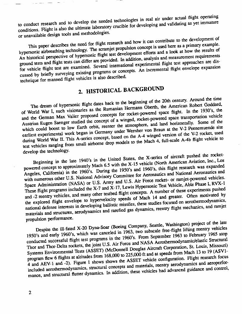
to conductresearchand to develop the needed technologies in real air under actual flight operating
conditions. Flight is also the ultimate laboratory crucible for developing and validating as yet immature
or unavailable design tools and methodologies.
This paper describes the need for flight research and how it can contribute to the development of
hypersonic airbreathing technology. The scramjet propulsion concept is used here as a primary example.An historical perspective of hypersonic flight test development efforts and a look at how the results of
ground tests and flight tests can differ are provided. In addition, analysis and measurement requirementsfor vehicle flight test are examined. Several international experimental flight test approaches are dis-
cussed by briefly surveying existing programs or concepts. An incremental flight envelope expansion
technique for manned flight vehicles is also described.
2. HISTORICAL BACKGROUND
The dream of hypersonic flight dates back to the beginning of the 20th century. Around the time
of World War I, such visionaries as the Rumanian Hermann Oberth, the American Robert Goddard,
and the German Max Valier proposed concepts for rocket-powered space flight. In the 1930's, the
Austrian Eugen Saenger studied the concept of a winged, rocket-powered space transportation vehicle
which could boost to low Earth orbit, reenter the atmosphere, and land horizontally. Some of the
earliest experimental work began in Germany under Wernher yon Braun at the V-2 peenemuende site
during World War II. This A-series concept, based on the A-4 winged version of the V-2 rocket, used
test vehicles ranging from small airborne drop models to the Mach 4, full-scale A-4b flight vehicle to
develop the technology.
Beginning in the late 1940's in the United States, the X-series of aircraft pushed the rocket-
powered concept to approximately Mach 6.5 with the X-15 vehicle (North American Aviation, Inc., Los
Angeles, California) in the 1960's. During the 1950's and 1960's, this flight research was expandedwith numerous other U.S. National Advisory Committee for Aeronautics and National Aeronautics and
Space Administration (NASA) or U.S. Army and U.S. Air Force rocket- or ramjet-powered vehicles.
These flight programs included the X-7 and X-17, Lewis Hypersonic Test Vehicle, Able Phase I, RVX-1
and -2 reentry vehicles, and many other testbed flight concepts. A number of these experiments pushed
the explored flight envelope to hypervelocity speeds of Mach 14 and greater. Often motivated by
national defense interests in developing ballistic missiles, these studies focused on aerothermodynamics,
materials and structures, aerodynamics and rarefied gas dynamics, reentry flight mechanics, and ramjet
propulsion performance.
Despite the ill-fated X-20 Dyna-Soar (Boeing Company, Seattle, Washington) project of the late
1950's and early 1960's, which was canceled in 1963, two subscale free-flight lifting reentry vehicles
conducted successful flight test programs in the 1960's. From September 1963 to February 1965 atop
Thor and Thor-Delta rockets, the joint U.S. Air Force and NASA Aerothermodynamic/elastic Structural
Systems Environmental Tests (ASSET) (McDonnell Douglas Aircraft Corporation, St. Louis, Missouri)
program flew 6 flights at altitudes from 168,000 to 225,000 ft and at speeds from Mach 13 to 19 (ASV1-
4 and AEV-1 and -2). Figure 1 shows shows the ASSET vehicle configuration. Flight research focus
included aerothermodynamics, structural concepts and materials, reentry aerodynamics and aeroperfor-
mance, and structural flutter dynamics. In addition, these vehicles had advanced guidance and control,

airdata,instrumentation, and telemetry systems. These instrumentation and telemetry systems providedextensive data measurement.
Length 68.82 In.Span 54.88 In.Height 32.79 In.
Wing sweep 70° (True)Wing area 14 ft2Nose tip radius 3 in.Leading-edge radius 2 in.
Average weight
ASV (structural) 1130 IbAEV (elastic) 1225 Ib
10°
93o_eg
Fig. 1. The ASSET vehicle configuration.
The second vehicle, a U.S. Air Force project called Precision Recovery Including Maneuvering
Entry (PRIME), used the ablatively cooled SV-5D lifting body (Martin Aircraft Company, Baltimore,
Maryland) (fig. 2) launched from atop the Atlas rocket. The primary objective was to study the flight
mechanics and aeroperformance of maneuvering reentry with cross range. Secondary objectives involved
aerodynamic and aerothermodynamic research. From December 1966 to April 1967, three test flights
(FV-1 to -3) were flown from low Earth orbit to a splash-down water recovery. Only FV-3 was
completely successful in this regard. Such successful unmanned lifting reentry vehicles as ASSET and
PRIME were coupled with the M2 and HL-10 (Northrop Corporation, Newbury Park, California) and
X-24B (Martin Marietta Aircraft Company, Baltimore, Maryland) series of lifting bodies for low-speed,
low lift-to-drag ratio approach and landing tests to clear the way for the operational space shuttle vehicleof today.
The supersonic combustion ramjet, or scramjet, engine shows great potential for hypersonic air-
breathing flight at speeds in excess of Mach 5. On the other hand, this engine has never been successfully
flight tested in its operational hypersonic speed regime at Mach 6 and above. In the 1960's, two projects
sought to develop scramjets in the flight test environment. One was the U.S. Air Force Scramjet Incre-
mental Flight Test Program which planned to use a Castor rocket carriage vehicle. The second involved
NASA Langley Research Center axisymmetric Hypersonic Ramjet Experiment strapped to the bottom of
3

theX-15. For severalreasons,theseprogramsneverreachedtheflight phase.Hallion (1987)providesexcellentdetailedtechnicaldescriptionsand discussions of the history of these projects.
_1666# "-' _o_m
Fig. 2. The SV-5D hypersonic research lifting body.
Recently, from 1987 through 1992, four Russian, dual-mode, scramjet flight tests were conducted
to about Mach 5.5 at an altitude of approximately 85,000 ft. Only the last two tests involved actual
combustion. Results indicate that short periods of supersonic combustion were achieved. Further details
of this project are given in subparagraph 7.5. Presently, it is uncertain what future developments may
be realized from this or other Russian programs.
3. FLIGHT TEST DEVELOPMENT OF HYPERSONIC TECHNOLOGIES
Scrarnjet-powered vehicles depend heavily on a very high degree of airframe integration. Such in-
tegration is need_ not only to increase volumetric efficiency and minimize drag, as with typical aircraft,
but also because a large part of the engine performance is derived from the airframe. Virtually the entire
underside of the vehicle serves as the "engine" in a full nose-to-tail sense. Unlike turbojet compressors,
the scramjet internal towpath, by itself, is geometricallY too simple to generate sufficient pressure rise
for combustion without the forebody. Likewise, thrust-producing extraction of flow momentum in the
exhaust is very inefficient with only an internal engine nozzle without a large external nozzle formed
by the underside of the aft airframe.
Subsections 3.1 through 3.3 describe the hypersonic, scramjet-based, airbreathing, operating enve-
lope and discuss the contributions and limitations of ground test techniques in addressing these condi-
tions. Ground test limitations highlight those areas of technology where flight test is especially beneficial
in developing the integrated vehicle concept and validating design methods. Flight test contributions
are also described.
4

3.1. Flight Operational Envelope
The hypersonic airbreathing flight regime is the most severe for any flight vehicle, including, for
example, orbital reentry vehicles, which fly at comparatively low dynamic pressures (fig. 3). To produce
sufficient levels of thrust, the hypersonic air breather must fly deep in the atmosphere at high dynamic
pressures (for example, nominally 2000 lb/ft 2) to capture and process enough airflow. This high dynamic
pressure, in turn, results in high aerothermodynamic heating and large structural airloads. Mach number
ranges up to and including Earth orbital speeds introduce changing chemical and physical conditions on
the airflow around the vehicle and through the engine. Such effects as chemical kinetics, flow ionization,
and real gas changes on the ratio of specific heats from ideal air (3' = 1.4) and the air viscosity come
into play because of the high speeds and temperatures generated. When encountered, such localized
atmospheric effects as wind shears, turbulence, and density pockets can significantly affect flight vehicleperformance and stability.
Flight testing a vehicle, its technologies, and its design methodologies can best be characterized
using a design and operational state space concept. This state space consists of such subelements as
the flight state, vehicle state, atmospheric effects, local flow conditions, and vehicle systems. Each
subelement must be fully explored through a blend of ground test, flight test, and analysis to developfully an operational vehicle.
The flight state is defined by vehicle velocity or Mach number and dynamic pressure conditions.
Figure 4 shows a typical single-stage-to-orbit (SSTO) flight envelope. Ranges of dynamic pressure,
total temperatures, and total pressures to be encountered are also shown. The flight envelope must be
fully explored by the actual test vehicle, especially when ground testing cannot simulate the proper
operating conditions with sufficient fidelity. The same is true for the vehicle state along its flightpath,
which includes such items as angles of attack and sideslip, acceleration load factors, and flight attitudeand rates.
350 x 103
r Flight envelopes300 | _ Airbrssthlng flight corridor m,
I'- --- _ EZ2:I _a_ ehunla ._,,,_^ / 3UO:000 ft _ X'15 airplane _i
,;_,u _-- 1_ ----- Dynamic pressure, Ib/ff2 _!2 :_ Dynamic
Flight 00 . _;._:%.._ ,, pressures,altitude, ;::_%_:_: _-ib/fl2ft 150 '!_ _'" 200
'_':"!......... _ 600
1: \ -1,ooo_-- 2,000
0 2 4 6 8 10 12 14 16 18 20 22 24 26 28Fllght Mach number
93O271
Fig. 3. Comparison of airbreathing and nonairbreathing flight corridors.

SSTO
flightenvelope
350 X 10 3 _ ,24,000 °Ro-. _ ,-, (_ _ _ Dynamic
Flight _
altitude,
H ! i
__ ----- Total pressure, ps a' " - .... Total temperature. °R
2 FIIOM Mach number
Fig. 4. Typical hypersonic airbreathing flight corridor.
Figures 5 and 6 show the range of unit Reynolds number and free-stream enthalpY represented
by the flight envelope shown in fig. 4. Both parameters are plotted as a function of free-stream Machnumber with scramjet operable ranges of atmospheric dynamic pressure. AdditionallY, the free-streamenthalPY plot in fig. 6 shows the constant heat addition contribution of hydrogen combustion at a fuel
equivalence ratio, _, of 1.0. Note from the extreme aerothermodynamic conditions illustrated in figs. 4
and 6 that the operational environment requires significant development efforts in hot structure conceptsand advanced materials to survive the thermal environment. Thermal stresses and materials effects
impart unique characteristics and problems to these hot aircraft compared with the cold aircraft of
today.
Isolating the scramjet engine from atmospheric environmental effects, angles-of-attack and -sideslip
sensitivity, or other sudden changes in the flightpath is much more difficult to accomplish than is the caseair chemistry, humidity, and atmospheric
wi h modern turbojet engines. Atmospheric effects include shears, and density gradients. Such local_amics Atmospheric dynamics include turbulence, wind or simulated
dyflow conditions as shocks, boundary layers, and base pressures must be properly generated
and investigated to understand fully the performance sensitivity of the scramjet to the atmosphere. These
effects, dynamics, and conditions must be addressed through flight test or ground test simulation.
Finally, the vehicle-technology state space is defined by the vehicle systems. Items to be addressed
here include geometry as well as material and structural fidelity. Scale effects, including geometry and
test time, are often important effectors in testing and validating requisite technologies. A build-up test
approach moves from system components to integrated systems tests and includes ultimately testingthe totally integrated flight vehicle. Various component and vehicle subsystems and controls must be
incorporated and evaluated in the sequencing of ground and flight tests.

107 2 4r
106
Reynoldsnumber,
per ffIO0
105
1040
Fig. 5.
/• • e
/ /• • 150
2 4 6 8 10 12 14 16
Free-stream Mach number
Unit Reynolds number requirements for hypersonic flight conditions.
225
18 20 22 24 26 28
93O273
Free-streamtotal enthalpy,
BTU/Ibm
Fig. 6.
10,000 - Note: total enthalpy, Dynamic
9,000 - ht = h + V2/2 o pressure _h=0atT=0 R ~ Ib/ft 2 ///
8,000-
7,000 - y
8,000 -
5,000
4,000 - Hydrogen combustion3,000 heat addition at ,_
1,000 _ .......
I I j0 5 10 15 20
Free-stream Mach number93o274a
Enthalpy as a function of Mach number.
3.2. Ground Test Facility Contributions and Limitations
Properly designed ground tests significantly contribute to successfully designing and developing
flight vehicles. Often, these tests are the best methods of isolating and addressing technical problems or
issues in a design through component tests or controlled experimental conditions. The results usually
7

form the genesis of databases and design tools, measurement and analysis techniques, and system design
validations which lead to developing the integrated flight vehicle.
On the other hand, practical limitations encountered in ground test facilities and techniques are par-
ticularly troublesome in the hypersonic flight regime. Such practical hardware problems as inaccuracies
of scale or size, lack of incorporating or simulating critical systems, and lack of properly represented
system integration arise because of facility volume or other operational limitations. Other facility limita-tions also arise, for example, brief test duration (milliseconds in shock tunnels when seconds are needed)
and limited Mach number ranges (a maximum of Mach 8 for long-duration wind tunnels). Often, real air
cannot be simulaed because of the need to test with other gases or to combustion-heat air for enthalpy
simulation. Heating, in turn, results in vitiated air (in other words, air containing combustion products
or contaminating particulates), or the chemical composition is otherwise changed because of oxygen
depletion and make-up. Other test problems include accurate Reynolds number simulation; pressure,
and temperature, or both, (cnthaipY) simulation at high Mach number and dynamic pressure conditions;
tunnel interference problems; and engine exhaust effects simulation. Figure 7 illustrates the problem
for hypersonics by comparing the ground test facility test envelope capabilities with the desired flight
operational envelope for an SSTO vehicle.
Tunnels
ArcShock
EZ:Z:Z_ Wind ,,,,,
Right corridor _..::.:._:._:_.i _|• ooeooeO,
• eeeooe(• eoooee(
250 X 103 "":::'" Dynamiceoeeo
::.:" ,. p_o,,"p'.
200 _ _ 200
Flight 150 _',_ 1_0 ialtitude,
14 16 18 20 22 24 26X1030 2 4 6 8 10 12
Flight velocity, ft/se¢ _o_5
Fig. 7. Existing ground test capabilities for hypersonic development.
3.3. Flight Test Contributions
Flight test is the ultimate validation of a design or technology development process. This process
is most often begun through predictive analysis and ground tests. The need for flight test vaiidation
is especially true of large, complex, integrated flight systems which frequently reveal some significant
surprises in flight.
8

The large,d_Ita-wingcd space shuttleorbiterprovides an excellentexample. This vehiclereenters
the atmosphere of the Earth from orbitat severeaerothcrmodynamic conditionsto a horizontallanding
similarto an airplane.Severalinterestingmisprcdictedaerothcrmodynamic heatingphenomena occurred
on the earlyshuttleflights.Some of thesephenomena wcrc advantageous, otherswcrc not. Examples
includereactioncontrolsystem jetinteractioneffectson higher thanpredictedanglesof sideslipduring
reentry,flow impingement angle-of-attackeffectson orbitalmaneuvering sysmm pod heating,wing
Icading-cdgcheatingfrom boundary-layerand shock interactions,and Predictionsof thermal protection
system surfacecatalysisheatingeffectson thelower sideof the vchiclc.Iliffand Sharer (1993) describethesephenomena, give othervchiclcexamples, and compare flightand ground testresults.
Another shuttleexample involves the effectsof misprcdictedboundary-layer transitionon vehicle
windward-side heating.Preflightanalyticalpredictionsand ground testsused smooth models as well as
an assumed sttrfaccroughness tomodel boundary-layertransitionlocationand time from initialrectory.
Actual tileinstallationrevealed thattheresultingsurfacewould bc much rougher than modclcd bccausc
of largegaps, unexpected rounded edges, and general surfacc unevenness from one tilcto thc next.
Although somc regions near the nose of the shuttleabout theccntcrlincwcrc well predicted,the aftend
of the vchiclcwas significantlymisprcdicted.Iliffand Shafcr (1993) note thatthismisprcdictionwasprobably caused by wind-tunnel noise masking the modeled surfaceroughness.
Figure 8 shows that thc transitionwas predicted to startat just over 900 scc into the reentry
phase and then graduallymove forward to thc nose region.In fact,transitionoccurred much laterthan
predictedand, once started,almost instantaneouslypropagated to the front of the vchiclc. Figure 9
shows the net result--a delayed rise in surface temperature. In turn, this unexpected, advantageouseffect resulted in lower surface temperatures and structural heat load than had been predicted.
,.oF ! q s -2•g ['- : b _ S.gm dm
.8_. i _ ........ Predictions
:F\X/L "
@-' I-%0 "'"
1000 1200 1400 1600 1800
Entry time, 8oc .o_
Fig. 8. Comparison of predicted and measured transition times for STS-2 (modified from Iliff andSharer 1993).
Mispredictions could cause problems with structural and materials integrity or active cooling system
performance because of higher than predicted surface temperatures and heat loads. Flight data from
9

such cases can be fed back into the analysis and ground test techniques to improve future prediction
and modeling methods.
Temperature,°F
Fig. 9.
2500 r- .----- Flight data
I -- O-- TOrldJ:ltloPredlctl°n
2OOO_'- iNN\
// _ SO0 800 1000 1200 1400 1600 =_1800
0 zuu .,v Time trom entry Interface,sec
Lower surface temperature comparison at X/L = 0.7 (modified from Iliff and sharer 1993).
4. ANALYSIS AND PREDICTIVE DESIGN TOOLS VALIDATION
Developmental flight test aims to develop, validate, or both, mathematical analysis methods and
other predictive design tools. Some design tools are based on physical and mathematical theory. Oth-
ers are empirically derived models based on experiments which predict a phenomenon or estimate the
system performance and operational characteristics. In either case, these analytical methods must be val-idated for the unique, extreme hypersonic flight conditions. These conditions include high temperature,
high Mach number, and low-to-high-pressure effects not normally required of traditional airbreathingaerospace vehicle design tools. These methods must also evaluate complex geometry and systems for a
complete, nose-to-tail analysis of the flight vehicle performance under conditions of engine combustionand reacting flows. Current computer codes or models are only valid for restricted flow conditions, for
example, with no combustion physics; simplified geometries; or isolated vehicle components, such as
the vehicle forebody.
A prime example of analysis methods validation is the set of Computational Fluid Dynamics (CFD)
codes which are being developed for design of future hypersonic alrbreathing vehicles. These codes are
typically versions of the Navier-Stokes fluid dynamics equations which assume uniform, homogeneousflow with no chemical reaction or specie diffusion. Modern CFD computer codes have different analysisschemes. Such schemes include various time or space marching of the computations, geometry or spatial
griding schemes, and methods of handling changing viscosity effects. Other recent computationalfeatures include embedded mathematical or empirical models to account for such effects as turbulence
and chemical reactions. These powerful codes show great promise for computing full, three-dimensional,
reacting continuum flows with viscous effects. Developmental problems to overcome include long,
expensive computation time; complex, dense gilding of the vehicle geometry and surrounding flow; and
10

accurate representation of nonideal flow physics and chemistry. Specific validation objectives include
checking the ability of the general Navier-Stokes equations to compute flows under high-temperature
and low density conditions. Air chemistry changes from high gas temperatures include exciting atomic
vibrational modes, molecular dissociation, and ionization. Results include chemical radicals, free atoms,
and charged particles. Figure 10 shows that these effects, in turn, result in changing the perfect gasratio of specific heat of 1.4 at ambient conditions to lower real gas ratios approaching 1.2 at 5000 °R
(White 1974). In turn, these changes affect flow viscosity and reaction chemistry. Low density effects
result in the need to analyze flow for noncontinuum effects. This need is not inherent in the theoreticalbasis for the Navier-Stokes equations.
Ratio ofspecific 1.3
heat
1.10
Fig. 10.
1 2 3 4 5x 10³Temperature, *R
¢3027g
Specific heat ratio for air (modified from White 1974).
Other flow complexities to be accounted for in CFD include viscous effects, such as low-momentum
boundary-layer formation; shock boundary-layer interaction; and flow separation caused by large adverse
pressure gradients, geometry discontinuities, or shocks. Additional factors for analysis will include
accurate boundary-layer turbulence transition, correct turbulent mixing in the combustor, and vortical
interactions. Such factors cause large flow pressure, surface friction, acoustic loads, and heat flux
changes with direct effects on vehicle operation and performance. Shih and Neumann (1091), Marvin
(1992), and Marvin (1993) give detailed descriptions of CFD validation issues and requirements.
5. FLIGHT TEST TECHNIQUE CONCEPTS
Subsections 5.1 through 5.4 examine possible flight test concepts for enhancing technology devel-
opment using several approaches. These approaches include subscale captive-carry and air-launched
free-flight concepts. Use of subscale hardware, its issues, and limitations are also discussed. The valueof full-scale integrated flight vehicles is addressed.
11

5.1. Subscale Captive Carry
Depending on the resolution of such issues as required hardware scale, needed degree of system
integration, and desired aim-test condition achievability, many useful flight experiments can be conducted
with small subscale devices in a captive-carry mode aboard flight vehicles.
As used here, the term captive-carry refers to an experiment package or testbed platform in which
perhaps several experiments can be simultaneously mounted. The package or platform is permanentlyattached to its carriage launch vehicle. Then, the vehicle propels the package or platform to the
experimental test conditions for a finite time. These flight experiments can complement and correlate
with ground tests and can achieve such conditions as real gas effects or higher test Mach numbers that
are not attainable on the ground. Carriage vehicles can vary from rockets to aircraft depending on the
experimental device, test conditions, risk assessment, and degree of mission control needed.
Rocket launch vehicles usually cost less and provide a less risky approach to carrying experiment• " les achieve significant lift weight and accelerate to very high
acka es aloft than atrcraft. These vehlc. _ " back Ex riment configuration (fig- 11).P g .... ,---- ^,, examnle xs the Pegasus Ptggy pehypersonic Macn numoex_. #_,, rThis joint Advanced Research Projects Agency (ARPA) and NASA Dryden program is being carried
out with the Orbital Sciences Corporation, Fairfax, Virginia, using a NASA Dryden B-52B aircraft
(Boeing Aircraft Company, Seattle, Washington) to air-drop the rocket from 43,000 ft at Mach 0.8.
Curry, Mendenhall, and Moulton (1992); Noffz et al. (1991); and Noffz et al. (1992) report on
current basic hypersonic experiments in data sensor technology; airdata measurement; and aerodynamics,
aerothermodynamics, or both.
Disadvantages of rocket concepts often include a high degree of experiment integration requirement,
autonomous control, limited number of missions and achievable test conditions, lack of recoverability
and loss of the test payload, and flight along atypical (nonballistic) depressed trajectories. Increased
payload complexity, system operation, and highly modified trajectory control systems result from thesedisadvantages. Such unmanned test flights axe usually unrecoverable or are recovered using risky, com-
plicated procedures. Recovery of the test component device is highly desirable for post-test inspection.
Aircraft captive-carry flight experiments are limited to approximately Math 3 and below. Figure 12
shows the NASA Dryden SR-71A testbed aircraft (Lockheed Advanced Development Company, Bur-
bank, California). This aircraft testbed has been under study to conduct large-scale external burning
tests for base-filling drag reduction to Math 3 (fig. 13). Hicks (1992) provides further discussions of
this concept.
Advantages of using aircraft instead of expendable rocket launchers center on mission flexibility
to control the experiment, maximize success by flying to precise aim-test conditions, adapt to changing
mission conditions, modify test objectives in-flight, cover multiple test conditions simultaneously in a
given flight, and recover the experimental package for post-test inspection and reuse. Aircraft also carry
large-to-full-scale devices, highly integrated systems, or both, aloft for maximum test fidelity.
(_ Pegasus is a registered trademark of Orbital Sciences Corporation, Fairfax, Virginia, but this vehicle was developed as
a joint private venture between Orbital Sciences Corporation and Hercules Aerospace Corporation, Magna, Utah.
12

Disadvantagesof using aircraft include high cost resulting from complex experiment packageintegration and accompanying extensive aircraft modifications, flight and range operation expenses, and
high flight safety requirements for a man-rated system. Flight certification and clearance for such testscan be very involved, drawn-out affairs which result in added program cost and time.
Fig. 11.The Pegasus Piggyback Experiment configuration.
EC89-0206-3
ORIGINAL PAGE
BLACK AND WHITE PHOTOGRAPt.I
13
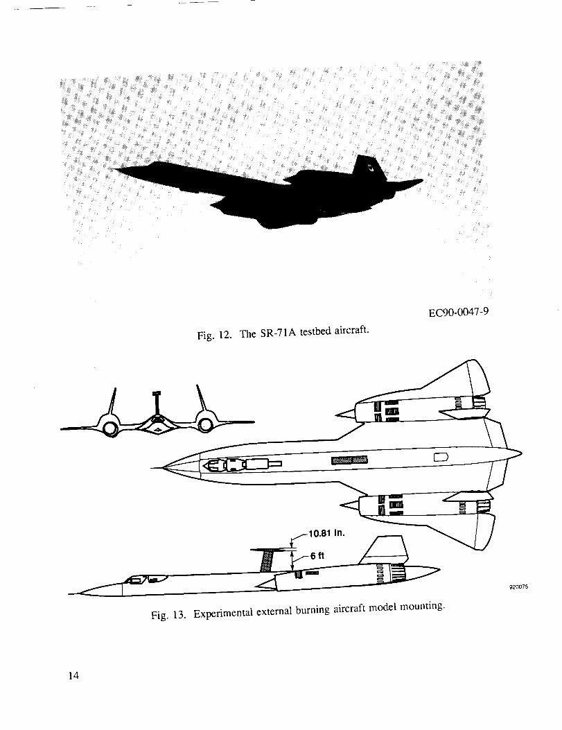
Fig. 12. The SR-71A testbed aircraft.
EC90-0047-9
Fig. 13. Experimental external burning aircraft model mounting.
920075
14

5.2. Air-Launched Free Flight
Air-launched free-flight experiments are especially valuable for testing large subscale, highly in-
tegrated systems or complete flight vehicle concepts. Ultimate system or vehicle performance and
proof-of-concept demonstration can best be achieved by free flight. Free flight is defined here as the
experimental package or testbed platform which is separated or launched from a carriage vehicle to flyto and operate independently at the aim-test conditions.
The value of a free-flight device can be seen, for example, in demonstrating and measuring thrust
production in a high speed (Mach 6 and above) scramjet. A free-flight vehicle allows direct assessment
of the net thrust minus drag production without being encumbered by additional carriage vehicle drag;control requirements; and aerodynamic or structural interference, or both, from the launch vehicle.
Launch vehicle integration may still be as or more complex than that of captive-carry experimental
devices. On the other hand, operation and control can be simplified using the nominal trajectory
sequence of the launch vehicle, such as the normal low dynamic pressure ballistic flightpath of a
rocket. The control and maneuvering burden of flying at the desired deep atmospheric trajectories for
airbreathing performance can then be placed on the experimental free-flight vehicle.
Given sufficient volume for a crew station and for control functions, test vehicles could be piloted,
which increases flight safety, mission flexibility and experiment control, and recovery of the experimental
vehicle. This capability is particularly valuable from a concept development point-of-view if the man-
machine interface technology needs for an operational vehicle are required. For developmental purposes,however, a manned system should not be considered a requirement. The negative side of such man-
rated systems is that vehicle costs for added systems and complexity as well as for flight certifications,systems, and operations can be quite high.
Careful consideration must be given to the desired end-launch conditions for the flight experiment.
Large, integrated, free-flight vehicles could be launched at subsonic-to-supersonic conditions and then
accelerated to the aim hypersonic test conditions. Figure 14 shows the mothership, NASA Dryden
B-52B. This mothership can air-launch X-15-sized vehicles of up to 25,000 lb and 50-ft long from a
wing pylon at approximately Mach 0.85 and from an altitude of 40,000 ft. The NASA Dryden SR-71A
testbed vehicle can air-launch experimental 20,000-1b, 60-ft long vehicles at speeds of approximatelyMach 3 at altitudes of approximately 85,000 ft.
Figure 15 shows the NASA Shuttle Carrier Aircraft (SCA) air-launch platform. This platform is
similar to a 747 (Boeing Aircraft Company, Seattle, Washington) and can launch very large experimental
vehicles of from 150,000 to 200,000 lb, at approximately Mach 0.6, and at an altitude 25,000 ft (Fulton
1977). Issues of an appropriate testbed center around the size and weight of experimental flight vehicle
and on the desired launch energy and aim-test condition. For example, in the latter point, supersonic
launch conditions of approximately Mach 3 would be needed to start and test a ramjet engine. This need
could, of course, be achieved by accelerating to the Mach 3 aim-start condition with a rocket if vehicle
size, weight, and integration could be accommodated. Such a supersonic launch point could also save
the experimental vehicle acceleration fuel and result in significant savings in size, launch weight, andtotal fuel load to reach test conditions.
15

Fig. 14. TheB-52B aircraft.
S
EC91-238-3
EC92-05282-1
Fig. 15. The NASA Shuttle Carrier Aircraft air-launch platform.
5.3. Scale Selection
To be successful, results of subscale flight experiments must apply to final, full-scale devices. This
application of results includes not only the question of viability in validating a scaled-down version of
16

a given systemdesign,operation,or both, but also in developingandvalidatingdesignanalysistools,groundtestmethods,andmeasurementtechniques.At best,theflight dataproductshoulddirectly applyto thefull-scalesystem.As a minimum,throughanalysisandothermeans,theproductshouldbeusefulwhenextrapolatingto the desiredfull-scale results. In any case,subscaleflight dataare valuableforvalidatingdesignandanalysistools,developingsomephenomenamodeling,andstudyingcertainaspectsof thephysicalsystembehavior.This approach,in turn, requiresinitial experimentdesignanalysisandsensitivity studiesto quantitativelyassessproper scaleand systemfidelity before the subscaleflightexperimentis fully developed.
Examiningthe difficult subscalescramjetcase illustrates the importance of scale selections. Ade-
quate test scale of a scram jet design has been debated for many years. The basic issues to be resolved
include engine flowpath physics and chemistry fidelity, engine design features to be incorporated or the
degree of system operation mechanization desired, and system component fabrication and mechanization.These issues are briefly examined in sub-subsections 5.3.1 through 5.3.3.
5.3.1. Flow Physics Fidelity
Reproducing the proper flow physics and chemistry is the greatest technical issue for a subscale
scramjet experiment. The expediency of using subscale devices can mask or totally miss simulating
key flow parameters which affect system operation and performance fidelity. Figure 16 shows that
engine operation begins with the flight vehicle forebody compression process ahead of the inlet where
Reynolds-number-regulated viscous effects begin to develop the inlet boundary layer.
/'- Laminar-turbulents / boundary.layer
j/" / transition withIncreased heat flux
/ /-Potential boundary./ /-Ramp shock / layer separation
f / / _ and reattachment
Vehiclebow shoc
laye r g rowt hdec reas_ing, _ _<,_'*_ Scramje'_'t'_nengl-ne ::hgalust
free-stream mass captureJ __-_-..-.__.--._._._._._'!__..'._'=.'.__
Shock InteractlonsJ / _Cowl shock
Inlet flow spillagewith Increased drag _o_
Fig. 16. Scramjet scaling issues.
Proper boundary-layer transition from laminar to turbulent flow conditions must be correctly located
and accurately achieved to simulate the right level of heat flux, friction drag on through the engine,
and boundary-layer displacement thickness and turbulent velocity profile at the inlet entrance. Forebody
shock patterns and compression performance must also be duplicated, positioning shocks to avoid
boundary-layer separation in the inlet and shock interaction effects on flow distortion and losses. The
17

compressionprocess;boundary-layerconditions;inlet-combustor component isolator function, if used;
and system of generated and reflected shocks must also be accurately simulated through the inlet to the
combustor entrance. As with many other influences, these shocks are propagated downstream and affect
the rest of the engine operations. Leading-edge radii of cowl lips, struts, and other inlet components
must be considered relative to simulating proper heat loads, shock formations, and drag. These elements
can affect inlet kinetic energy efficiency, which is a component performance measurand.
5.3.2. Combustor Operation Mechanization
In the combustor, concerns regarding scaling issues include the combustor burning length. In turn,
this length involves combustion dwell or residence time for proper chemical kinetics simulation and
adequate fuel-mixing length. Chemical kinetics can be scaled to a limited extent in the combustor and
nozzle by combining the correct length and static pressure. First, analysis must be performed to assess
to what degree this combination is achievable for a given test configuration. Additional concerns include
combustor skin friction and other drag sources; wall film cooling, if used; and internal static pressure,
temperature, and local flow Mach number.
Injection fuel temperature can also be a key issue, especially if regenerative cooling with fuel
is used. Inability to simulate the desired injection fuel temperatures (for example, the autoignition
temperature of 1800 °R for hydrogen) can cause fuel ignition delays. It can also affect reaction rates,
impact fuel and air shear-mixing effects, and impact fuel thrust adversely. The nozzle expansion process
must, likewise, correctly simulate chemical kinetics and skin friction as well as external base pressures.
5.3.3. Hardware Fabrication and Mechanization
Once proper flow physics has been resolved, practical engine fabrication and integration must be
addressed. First, engine component geometry relationships must be maintained, but a limit to size
manufacturability and to operational mechanization and control exists. Examples include the diameter
or slot height of fuel injectors and the flow insertion mechanisms, if used. This limit also involves
flameholding devices and variable-geometry simulation, activation, and position sensing, where applica-
ble. Other mechanical insertions, retractions, or both, of an instream device may be involved. Selected
critical engine subsystems, such as pumps, control sensors, and actuators, may also be included.
Other issues include system volume adequacy for active internal structural cooling, instrumentation
installation, and volume for such engine subsystems as control actuators, sensors, and pumps. If actual
flight materials are not used, then substitute materials must be structurally, chemically, and thermally
comparable. Ground test requirements for flight-to-ground data results correlation must also be included
relative to the available ground test facilities and conditions. Finally, minimum performance levels
desired must be considered to properly evaluate a design or demonstrate its operation or capability.
5.4. Integrated Flight Vehicles and Envelope Expansion
This concept for a large, integrated, aerospace plane flight test program is based on a conservative,
incremental approach to expanding its operating envelope. The approach emphasizes flight safety and
careful exploration of the integrated technologies. This perspective assumes that these first generation
vehicles will, for the most part, explore new, unknown territory in the flight regime as well as in the
18

integratedtechnologies and systems. As a result, program risk will be high, vehicles and flight facilitieswill be limited and expensive, and operational issues will be complex.
Conceptual/y, the flight test program could consist of two major phases. The first phase could
expand the flight envelope to near the vehicle operating limits. The second phase could involve more
dedicated flight research than the first. The flight envelope expansion phase would complete a functional
check of the aircraft systems, validate system performance and operating characteristics, and define
vehicle operating limits and anomalies. This vehicle flight clearance and system flight certification
would include the airframe structure, engines, controls, and subsystems and collect a limited amount of
flight research data. Once the flight envelope is cleared, the dedicated flight research phase would beflown within that envelope to investigate specific research objectives.
The flight envelope expansion program could be implemented on the basis of key flight clearance
milestones. For example, the separate engine operating modes could be used, and each new test could
be keyed to the engine mode transition points. This concept is a strong function of the specific vehicle
configuration and characteristics and may need to be modified on the basis of controls or structures
milestones. The incremental method would either proceed piecemeal directly along the design mission
trajectory, such as an SSTO profile, or could approach that trajectory in a build-up fashion from off-design flight conditions, such as low dynamic pressure (high altitude) conditions.
The basic idea of such a flight envelope expansion program is to operate from and return to a single
test site. This procedure maximizes flight safety and simultaneously eliminates or minimizes the need
for multiple test sites with the attendant expensive duplication of ground facilities. The aircraft would
accelerate and cruise outbound at an already cleared airspeed. Next, it would turn and accelerate to the
new aim-clearance Mach number while returning to the recovery site. If problems were encountered
at the newly expanded envelope point, then the vehicle could be safely powered down and returned to
the landing site in the power-off or glide condition. An auxiliary rocket engine mode could assist in
the acceleration to test conditions, if needed. The wings-level stabilized flight condition would be used
to obtain the necessary flight clearance data at the new aim Mach number. Then, the aircraft woulddecelerate, return to the recovery site, and land.
For a vehicle operating out of Edwards AFB, California, the flight corridor would be over land
with the maximum available test range or, at least, within landfall from over water (fig. 17). A safe
landing could always be achieved. At speeds up to Mach 3, flight testing would be completed within
the local area. For high Mach numbers of approximately Mach 12 and above, the flight corridor would
extend outbound using the same basic flight profile. This flightpath extension allows the aircraft enough
ground-track distance to accelerate to the aim conditions, stabilize for up to 1 min, and then decelerate
and return to the recovery site. Once the ground track was insufficient for vehicle acceleration to test
conditions, the flightpath could be reoriented to take maximum advantage of the available landmass. This
process would continue until the maximum operating conditions were reached or insufficient landmass
was available at these high hypersonic Mach numbers for a safe recovery. Then, in the case of an orbitalvehicle, the vehicle would have to accelerate to orbit.
19

110° 100°
70* ._--- Acceleration...... Cruise------ Glide
35° s -IncreasingMach number
acceleration
Edwards AFBKennedy Space
Center
Fig. 17. Ground tracking of flight envelope expansion missions.
6. INSTRUMENTATION REQUIREMENTS AND STATE
OF THE TECHNOLOGY
Flight instrumentation systems for hypersonic airbreathing vehicles have lagged behind the devel-
opment of other requisite technologies. Bogue and Erbland (1992) note that because of the speed rangeinvolved and the extreme thermal and pressure flight conditions, instrumentation systems have had new
demands placed on them. These systems include data acquisition and conditioning, recording, intercon-
nects, telemetry, and transducer technology. Above all, the fundamental flight system requirement is
that the flight instrumentation package, relative to ground test systems, must be as compact, lightweight,
and rugged as possible to function in and survive the flight environment. Because the instrumentauon
system is potentially the highest maintenance and checkout component for aircraft operability, desired
measurement sensitivity will have to be balanced with a high degree of system robusmess to ensure
reliability and maintainability.
The ground test system must have strong commonality with the flight test system for a given
.. t,,_,_l,_o_a development effort. That is. the type. .. --,-:--ultaneously, so critical data correlauonstransducer and the data processing sy_,_ ' . number, location, and distribution density of. thet_.-------_ . " ...... m must ve consloereu n--
can be made.
Measurement data quality for defining system design specifications and performance criteria must
be addressed. In many cases, either because of the new, severe operating environment or the fact that
many of the transducers are now being developed, adequate criteria and calibration methods do not yet
exist. These criteria and methods must be established through experiments before they can be applied.
Subsections 6.1 through 6.5 give an overview of the instrumentation operating environment and data
acquisition requirements. Examples of transducer development and some of these unique challenges are
given for hot structures strain gages, instream flow-field measurement methods, and airdata techniques.
20

6.1. Data System Operating Environment
The data system operating environmental challenge includes such factors as severe temperatures.
These temperatures induce chemical, physical, or both, changes in transducer systems and the supporting
structures and affect accuracy and life cycle operability. Other environmental challenges include high
heat flux of up to 90,000 Btu/ft2-sec (especially with localized shock-surface interactions), high-intensity
acoustic fields of up to 200 dB, oxidizing or reducing atmospheres, and ionized plasma gas conditions.
Such environmental effects introduce chemical, mechanical, or electrical changes in the operating envi-
ronment and data system components. In turn, these changes affect the installation, component make-up,
and operation. Local high-temperature flow fields about the flight vehicle induce gas ionization and
dissociation, thereby creating a conductive plasma condition which affects transducer operation.
Instrumentation system design must account for operating in very hot environments ranging from
heated external vehicle surfaces of up to 2000 °F to hot internal airframe compartments of, perhaps,
500 °F to internal engine stagnation temperatures which approach or exceed 5000 °E Surface heat flux
without shock interactions would nominally be up to 2000 Btu/ft2-sec but could approach 5000 Btu/ft 2-
sec at certain stagnation regions. New, advanced materials to handle the aerothermodynamic environ-
ment require new transducer installation techniques, especially with such advanced materials as metal
matrix, carbon-carbon, carbon-silicon-carbide, and ceramic composites. Using several different struc-
tural materials in differing parts of a vehicle means facing different thermochemical environments and
structural design concepts. These concepts affect installation techniques as well as calibration and mea-
surement compensations. Additional application problems include surface attachment with advanced,
high-performance adhesives and drilling holes through the materials for transducer installation withoutcompromising material, structural, or active cooling integrity.
Of course, any thermal, electromagnetic, chemical, or mechanical interactions of the installed trans-
ducer must be minimized or accounted for to avoid affecting the quantity that is being measured. For
example, the surrounding structure material stiffness, yield strength, and creep at high temperature affects
transducer installation. Differential expansion caused by different thermal coefficients among the sur-
rounding structure, transducer, and attachment medium can induce falsely sensed strains. These strains
would require development of temperature compensation calibration techniques. Transducer integration
must include consideration of small components that are chemically nonreactive and, once embedded
in the surrounding structure, arc a close enough physical match to avoid affecting the measurements.
Transducer survivability in thermochemical environments becomes a major question to be ad-
dressed. The need for transducer cooling or placing them in a thermally controlled environment adds
weight, volume, and system complexity to the flight vehicle. The need for intrusive versus nonintrusivesensors for a given application, such as flow-field sampling, must be addressed.
6.2. Data Acquisition Challenges
In addition to advanced transducer development, equal attention must be given to developing the
data processing and transmitting system if the measurement information is to be truly useful. Data
processing and signal conditioning systems must be adapted to, perhaps, very large aircraft that often
require thousands of parameters to be measured at very high sample rates. Some of these parameters
are also used in vehicle flight avionics and other control functions, so they must be compatible with the
21

normalaircraft operationalsystems. Onboard computers may be necessary to sort and reduce the data
measurements, perform second or third generation computations on the measurements, and distribute
these computations to several subsystems, including telemetry downlink.
Air-to-ground telemetry problems to surmount include antenna location and survivability under
extreme aerotherrnal conditions. High data transmission rates in the several megahertz range coupled
with a large number of parameters sampled over a wide frequency range to very high levels (thousands
of samples per second) may require extensive data compression and multiple data downlink paths with
ground-based data reconstruction. Data transmission through potential vehicle plasma sheets, vehicle
tracking, and signal acquisition and relay over large ground tracks at high speeds needs to be resolved.
Possible approaches include global-positioning satellites or an approach similar to the NASA Tracking
and Data Relay Satellite System.
In vehicles where volume and weight become critical because of vehicle size or mission goals,
the question of using collocated or distributed instrumentation system components arises. If sufficientvolume is available, collocated systems are easier to integrate and operate. Nevertheless, long, large
metallic wiring bundles from individual transducer groups to the data processing units are heavy and
may also be limited by available routing volume. One approach uses sapphire or coated silica fiber
optics which operate at temperatures up to 2000 °F to replace the wire bundles with lighter, more
compact data transmission lines.
Distributed system components located nearest the respective transducer sets may be the best
approach to shorten wiring and decrease system complexity if sufficient volume and cooling needs can
be met in those areas. If the electronic components require environments similar to room temperature,
then the compartments may require special cooling. Otherwise, data processing units with the ability to
operate in high-temperature environments must be developed.
6.3. Hot Structure Strain Gages
New measurement transducer technology is in a state of high flux. Hot structure strain sensing
using surface-mounted resistance strain gages or remote-sensing techniques provides an excellent ex-
ample. Williams (1992) reported on noncontact remote sensing. This report describes research into
such concepts as laser speckle strain measurement, phase-shifting interferometry, and X-ray extensome-
try. Another area involves high-temperature resistance strain gages. For example, palladium-chromium
(fig. 18) or iron-chromium-aluminum gages, and advanced attachment and calibration techniques are
being developed and ground tested to temperatures of 1000 to 2500 °F (Lei and Williams 1990; Holmes
and Moore 1992; and Lemcoe 1992).
Figure 19 shows one of the hot structure strain gage development problems known as apparent
strain. Thermal coefficient of expansion differences between the structure being measured, the strain
gage, and the attachment medium induce false strain levels. Material phase changes within the gagealso contribute to this erroneous or apparent strain level. This problem is especially acute in the iron-
chromium-aluminum gages. Actual strain levels caused by load are typically 100 to 2000 /._strain.
Actual strain can be highly distorted with apparent strain errors of up to 14,000/._strain at temperatures
approaching 1500 °F. Temperature compensation techniques are being developed by electrical resistance,
calibration correction, or both, methods under thermal cycling to correct for these errors. This figure
22

alsoshowstheeffectivenessof thesetechniquesfor palladium-chromiumandiron-chromium-aluminumgages.
Fig. 18. Two palladium-chromiumweldablestraingagesspot-weldedon an SCS-6/Beta21S TMC[0,90,0].
6.4. Instream Flow-Field Methods
Pitot rakes can be used to measure instream flow conditions but probably must be cooled for most
applications. Figure 20 shows a new concept being developed for intrusive flow-field measurements
(Graves et al. 1993). A retractable rake must be used to avoid disturbing the flow at critical operation
points. Expendable probes, designed to burn off after a few seconds of pretest measurements, are also an
option. Fiber optic microphones, which operate with a frequency response to 100 kHz with a dynamic
acoustic range of 130 to 190 dB, are being developed for operation at 2000 °F. Figure 21 shows small
skin friction devices. Chadwick and Schetz (1992) describe development of these small devices for usein engine combustor and nozzle applications.
Nonintrusive laser diagnostics have been in routine use for 25 or more years in the ground laboratory
environment. Only recently, however, have efforts been underway to adapt these methods to flight.Cooling, size, and ruggedness to survive shock and vibration are being pinpointed for solutions for
flight application. Instream laser measurement capabilities include flow velocity, temperature, densitycomponents, and flow chemical constituency measurements.
Figure 22 shows a laser absorption system being developed for in-flight measurements. Cavolowskyand Newfield (1992) describe this developmental technique for measuring engine combustor exit flow-
field constituents. These constituents include the hydroxyl (OH) radical, water vapor, and oxygen todetermine combustor efficiency.
23

14X10 3l- ---- Uncompensated Iron-chromium- /
.. k aluminum gage J-lz F _-- Compensated Iron-chromium- /_
.,. k aluminum gage / ,r,u F ---- Compenssted palladium- //
8_- chromlum gage //
oi___. L "_'.. _ ,, -'"s" F ",_.._ ...... E.,, S| "_"'---------'--_.--:'-"_-- , _ t t
-4 - 600 800 1000 1200 1400 16000 200 4uu o
Temperature, F _o310
Fig. 19. Temperature effects on strain gage performance.
Pressure measurementposition, In.
10
9
7
Enthalpyirement
position
6
Fig. 20. Probeless boundary rake (modified from Graves et al. 1993).
24

Fig. 21.
Loo zub
water out -__ water In
Skin friction balance, DCAF 2ed DCAF entry design (Chadwick and Schetz 1992).
6.5. Airdata Techniques
Airdata measurements of Mach number or velocity, angles of attack and sideslip, altitude or ambient
pressure, ambient temperature, and dynamic pressure or density are key to evaluating and controlling
airbreathing flight vehicles. Potential measurement systems include robust onboard inertial and pressure
systems. These data can be combined with data from remote radar tracking or satellite global positioning
system (GPS) for vehicle position data. Another valuable source of airdata is balloon-borne (rawinsonde)
sensing of ambient pressure and temperature and of local winds. Standard pitot-static methods for
measuring airspeed and altitude and traditional techniques for measuring angles using deflection vanes
or pitot-statics no longer apply at hypersonic speeds because of heating, aerodynamic, and pneumatic
lag problems. Additionally, accuracy of these older methods needs improving in several instances.
Angle-of-attack measurements for flight control and system testing provides an excellent example ofthis need.
Figure 23 shows scramjet thrust and mass flow sensitivity to changing angle of attack. As little as
a 0.1 ° change in angle of attack can cause a 1 percent change in thrust because of the corresponding
change in captured airflow at the inlet. Standard angle-of-attack measurement accuracy for subsonic-to-
supersonic aircraft is 4-0.25 °. Today, hypersonic flight not only needs a reliable way to measure angle
of attack but also needs to measure this angle to an accuracy level of 4-0.1 °. A sensitivity analysiswould, likewise, show similar accuracy improvement requirements for Mach number and altitude.
7. INTERNATIONAL FLIGHT TEST CONCEPTS
Subsections 7.1 through 7.5 survey current work in hypersonic flight testing in the United States,
France, Germany, Japan, and Russia. This survey illustrates the wide range of approaches and possibil-ities which exist for technical contributions from the flight test arena.
25

/ \
\
Fiberoptic pitch assembly
Optical /_
fiber _
Collimatinglens
_. "q,I
I-ilter ---_ _"T (c) Inlet probe configuration.Focusing / __
ensUE_nPhotodiode _ lUll _ I / -- _ _Y II
Oeector_ ! ___ IIoe.c,o,c.,c..ssom__ _ _
"lies / I % _ - //(b) Fiberoptic and detector assemD . _/_ I _ _- //
_C:xm_bustor_ _ sect,on
(d) Combustor exit and nozzle probe configuration.
Fig. 22. Optical probes in scramjet model.
assemblies-,
Optical fibers
930283
26

150 -- Note: 0.1 ° error In angle of attackequals a 1 percent changeIn scramjet mass captureand thrust
100
Thrustchange,percent
5O
0 I I I I I-2 0 2 4 6 8
Angle of attack, deg93O284
Fig. 23. Scramjet thrust sensitivity to changes in angle of attack at Mach 10.
7.1. United States
The United States has a relatively long history of hypersonic flight research. This history dates
back to the X-15 aircraft and other projects of the 1950's and 1960's. (See section 2.) These hypersonic
flight test programs centered on developing ramjets, unpowered vehicle aerodynamics and aerothermo-
dynamics, materials, guidance and control, and instrumentation sensors, such as those required for the
space shuttle. More recent examples of this flight test experience include the Sandia National Laboratory
(Albuquerque, New Mexico) Sandia Winged Energetic Reentry Vehicle Experiment vehicle (W'tlliamson
1992) and the ARPA and NASA joint program with Orbital Sciences Corporation aboard the Pegasus®rocket launch program (Curry, Meyer, and Budd 1992).
The National Aero-Space Plane Program has been developing plans for possible flight tests. These
plans involve the supersonic external burning experiment with a captive-carry device aboard the SR-71A
aircraft. Another proposal involves captive-carry experimental packages to be launched to hypervelocity
Math numbers aboard Minuteman II missiles. NASA and others have conducted numerous studies usingthe SR-71A aircraft as a supersonic launch platform for hypersonic research vehicles.
7.2. France
France's recent start on a scramjet development program is known as PREPHA (Debout 1991;
Debout and Mathieu 1992) and is presently focused on a ground test development phase. As a partnership
between the French government and industry, PREPHA is part of a national program which examines
conceptual two-stage-to-orbit (TSTO) and SSTO approaches to a low Earth orbit space transportation
system. This national parmership is funded by the Ministry of Defense and consists of the government
27

agency,ONERA, the aerospace firms of Aerospatiale, Dassault, and the Hyperspace engine consortium
of SNECMA and SEP.
The PREPHA objectives focus on scramjet propulsion development at hypersonic velocities up
to approximately Mach 8 to 10. Initially, ground test facilities with engine components and subscale
engine models will be used. The French have a strong interest in flight test development. Studies by
Falempin et al. (1992) were conducted to define future engine flight test programs, but specifics are not
available now.
7.3. Germany
Recent flight test studies in support of the German Aerospace Company (DASA) Saenger program
have centered on manned and unmanned flight testbed vehicles for subscale versions of its turboramjet.
Kuczera and Hauck (1992) and pl (1991) provide detailed descriptions of these studies. In brief, the
genesis program known as the Hypersonic Technology Experiment (HYTEX) was examined in various
forms. These forms ranged from manned horizontal takeoff to unmanned supersonic launch aboard such
aircraft as the NASA SR-71A. Such an aircraft could air-launch a HYTEX derivative supersonically
to study turbojet-to-ramjet mode operation and wansition or air-launch at Mach 3 to start and operate
the ramjet mode. Figure 24 shows some of the engine testbed flight test vehicle concepts. Studies are
continuing on into the new extended phase I program. Funding for these studies is from the German
Federal Ministry of Research and Technology (BMFT).
7.4. Japan
The National Aerospace Laboratory (NAL), National Space Development Agency (NASDA), and
Institute of Space and Astronautical Science (ISAS) of Japan have investigated advanced hypersonic
airbreathing technologies since the mid-1980's. Plans include subscale flight test development of aero-
dynamic, aerothermodynamic, composite materials, and control technologies. These plans are being
pursued through such flight concepts as the NASDA H-2 Orbiting Plane (HOPE), Orbital Reentry
Experiment (OREX), and ISAS Highly Maneuverable Experimental Spaceplane (HIMES). These ex-
perimental vehicles are to be launched from rockets for orbital reentry to automated, unmanned landingrecoveries. Additionally, ISAS conducted small-scale helicopter drop model tests of the HIMES vehicle
for landing tests in 1986 and 1987 (Inatani, Kawaguchi, and Yonemoto 1990) with a balloon-rocket
launch of a reentry test flight in 1992 (Inatani et al. 1992).
Plans axe also underway for a near-future joint NAL and NASDA flight test of automated landing
using a small-scale HOPE vehicle dropped from a helicopter. This project is designated ALEX for
Automatic Landing Experiment. Yamanaka (1992) discusses these and other plans for rocket-launched
experiments, including an air-turboramjet engine concept.
The air-turboramjet (ATREX-500) and scramjet Liquid-Air Cycle Engine (LACE) propulsion de-
velopments are currently focused on ground tests, but future flight tests of subscale engines are also
being considered. Such flight tests will probably follow Japan's preference for using unmanned, rocket-
launched, free-flight, experimental vehicles as engine testbeds.
28

HYTEX 6.8
Fig. 24.
HYTEX 5.6 HYTEX SE6.8
Gross takeoff
Length, Span, weight,HYTEX ft ft tons
6.8 101.4 37.1 26.25.6 89.6 29.9 17.2
SE6.8 68.9 19.7 5.5R6.8 49.2 13.1 2.8
HYTEX R6.8
The DASA Saenger project HYTEX vehicle concepts.
930285
7.5. Russia
Since approximately 1987, Russia's Central Institute of Aviation Motors (CIAM), headquartered
near Moscow, has conducted captive-carry flight tests of a complete subscale axisymmetric dual-mode
scramjet engine using the Hypersonic Flying Laboratory (HFL) (Kandebo 1992a). Five flight test
articles similar to those shown in fig. 25 were designed to conduct tests between Mach 5 and 6 at
altitudes from approximately 85,000 to 100,000 ft. These hydrogen-cooled and -fueled stainless steel
29

engines are approximately 4.20 ft long with an overall inlet diameter of 9 in. Three fuel injection
stations with cavity flameholders perform ramjet or scramjet operations. Besides the engine, the HFL
contains volume for the fuel and control gas tankage, control systems, and instrumentation package.
The axisymmetric concept was selected to flight demonstrate supersonic combustion operation and was
not used to directly measure thrust performance. This concept was also selected because it integrated
well with the cylindrical launch rocket. Figure 26 shows the launch rocket which is flown on a
depressed flight trajectory using a modified guidance and navigation system. To date, four of the five
nonrecoverable engine configurations have been flown. These tests involved two nonoperating, cold-
flow engines to evaluate the flight trajectory, vehicle integration, and system operation and two hot-flow
flights with combustion operation. Instrumentation has been basic and confined to wall static pressure
and thermocouple measurements with an emphasis on simple, robust systems to investigate supersonic
combustion in real air.
Fig. 26. Launch rocket with a modified guidance and navigation system.
3O

To date, two successful hot-flow flights have been achieved at speeds from Mach 5.3 to 5.6 with
reported sustained supersonic combustion times of 5 to 15 sec (Kandebo 1992b). ClAM plans to
continue with such flight tests using axisymmetric and planar-compression subscale engines at Mach
numbers up to, perhaps, 10.
8. CONCLUDING REMARKS
Nothing in the aeronautics discipline could be considered more difficult and challenging than
hypersonic airbreathing flight. The exciting, yet sobering, realization is that, in spite of a 30-year
developmental history, the scramjet-centered concept still has a long way to go before achieving practical
atmospheric flight from above Mach 6 to low Earth orbit. The possibilities from global hypersonic
cruise flight for commercial application to a low-cost space transportation system spur on world-wide
competitive technology development in many industrial countries.
Such vehicles could provide quick, on-demand access to space with a payload; rapid turnaround
capability; horizontal takeoff; other operational capabilities similar to those of aircraft; and rapid access
to distant points on the Earth for commercial travel and other applications. These vehicles must be
operationally reusable, reliable, safe, and cost effective and must have minimal negative environmental
impact on the atmosphere.
To achieve those operational requirements, this class of airbreathing hypersonic vehicles requires
a highly integrated airframe and propulsion system along with vehicle systems that operate in very
hostile flight environments. These requirements are especially true for the scramjet engine. The needed
hypersonic technology development is a complex, multifaceted problem compounded by limited ground
test facilities and unvalidated design tools or methodologies. A careful blend of advanced analysis,
ground test, and flight test is needed to design and develop these futuristic flight vehicles. Ultimate
validation of any integrated flight vehicle system can only be achieved by careful flight test. Indeed,
the flight arena is an indispensable aid in developing the individual technologies and design capabilities
for that integrated vehicle.
The potential rewards are tremendous. On the other hand, high costs and programmatic risks, cou-
pled with the complex, interrelated technical problems and lacking technologies, make this technology
truly the last great frontier of aeronautics.
31

REFERENCES
Bogue, R. and Erbland, P.: 1992, 'Perspective on the National Aero-Space Plane Program Instrumenta-
tion Development,' AIAA paper 92-5086.
Cavolowsky, J. and Newfield, M.: 1992, 'Laser Absorption Flow Diagnostics for Use in Hypersonic
Ground-Based and Flight Experiments,' AIAA paper 92-5088.
Chadwick, K. and Schetz, J.: 1992, 'Direct Measurements of Skin Friction in High-Enthalpy High-Speed
Flows,' AIAA paper 92-5036.
Curry, Robert E., Mendenhall, Michael R., and Moulton, Bryan: 1992, In-Flight Evaluation of Aerody-
namic Predictions of an Air-Launched Space Booster, NASA TM-104246.
Curry, Robert E., Meyer, Robert R., Jr., and Budd, Gerald D.: 1992, 'Pegasus Hypersonic Flight
Research,' SAE paper 921995.
Debout, B.: 1991, 'French Research and Technology Program on Advanced Hypersonic Propulsion,'
AIAA paper 91-5003.
Debout, B. and Mathieu, C.: 1992, 'French PREPHA Program: Status Report,' AIAA paper 92-5107.
Falempin, E, Forrat, M., Baldeck, J., and Hermant, E.: 1992, 'Flight Test Vehicles: A Mandatory Step
in Scramjet Development,' AIAA paper 92-5052.
Fulton, Fitzhugh L., Jr.: 1977, 'Shuttle Carder Aircraft Flight Tests,' Society of Experimental Test Pilots
21st Symposium, Los Angeles, California, Oct. 13-15.
Graves, Craig M., Moody, Henry L., Mitchell, James D., and Horn, Dennis D.: 1993, 'Enthalpy Probe
for Arc Heater Flow Diagnostics,' AIAA paper 93-2785.
Hallion, Richard P., ed.: 1987, The Hypersonic Revolution: Eight Case Studies in the History of
Hypersonic Technology---From Max Valier to Project PRIME (1924-1967), vol. 1, Aeronautical
Systems Division, Wright-Patterson AFB, Ohio.
Hicks, John W.: 1992, 'Development of a Hydrogen External Burning Flight Test Experiment on the
NASA Dryden SR-71A Aircraft,' SAE Paper 920997.
Holmes, H.K. and Moore, T.C.: 1992, 'High Temperature Strain Gage Apparent Strain Compensation,'
NASA CP-3161, pp. 211-222.
Iliff, Kenneth W. and Shafer, Mary E: 1993, 'A Comparison of Hypersonic Flight and Prediction
Results,' AIAA paper 93-0311.
Inatani, Y., Kawaguchi, J., and Yonemoto, K.: 1990, 'Status of "Himes" Reentry Flight Test Project,'
AIAA paper 90-5230.
Kandebo, Stanley W.: 1992a, 'Russians Want U.S. to Join Scramjet Tests,' Aviation Week & Space
Technology, vol. 136, no. 13, Mar. 30, pp. 18-20.
1992b, 'Scramjet Launch May Spur More Franco-Russian Projects,' Aviation Week & Space
Technology, vol. 137, no. 24/25, Dec. 14/21, pp. 70-73.
32
Kuczera,H. and Hauck,H.: 1992,'The GermanHypersonicsTechnology Programme--Status Report
1992,' 43rd Congress of the International Astronautical Federation, Washington, D.C., IAF paper92-0867.
Lei, J. and Williams, W.: 1990, 'PdCr Based High Temperature Static Strain Gage,' AIAA paper90-5236.
Lemcoe, M.M.: 1992, 'High-Temperature Strain Measurement Techniques: Current Developments andChallenges,' NASA CP-3161, pp. 127-170.
Marvin, Joseph G.: 1992, 'CFD Validation Experiments for Hypersonic Flows,' AIAA paper 92-4024.
1993, 'Dryden Lectureship in Research, A Perspective on CFD Validation,' AIAA paper 93-0002.
Noffz, Gregory K., Curry, Robert E., Haering, Edward A., Jr., and Kolodziej, Paul: 1991, Aerothermal
Test Results From the First Flight of the Pegasus Air-Launched Space Booster, NASA TM-4330.
Noffz, Gregory K., Moes, Timothy R., Haering, Edward A., Jr., and Kolodziej, Paul: 1992, Aerothermal
Test Results From the Second Flight of the Pegasus Booster, NASA TM-4391.
pl: 1991, 'HYTEX: Demonstrator fuer Hyperschallfluege bis Mach 5,' Luft- und Raumfahrt, Jan./Feb.1991, pp. 26--29.
Shih, P. and Neumann, R.: 1991, 'The Value of Sub-Scale Flight Tests in the Development of NASPVehicles,' AIAA paper 91-5048.
White, Frank M.: 1974, Viscous Fluid Flow, New York: McGraw-Hill.
Williams, W.: 1992, 'Strain Sensing Technology for High Temperature Applications,' AIAA paper92-5040.
Williamson, W.E., Jr.,: 1992, 'Hypersonic Flight Testing,' AIAA paper 92-3989.
Yamanaka, T.: 1992, 'Overview of Japanese Aerospace Plane,' AIAA paper 92-5005.
33

REPORT DOCUMENTATION PAGE o.s Noo;,o4-o1=_ i _mmd _ tv,,_i_, 1 h_r r_ _i_,,-,r,;, Indudhagthe tm_ tot r_."...:J.4j Irmr,__::_-_.,9_,,,;-,;,_ _:_ii __a__sou_,
k;.i;-_y ' _,ll.lm1204, A,-Ir_.,,_, VA.ix_..i-'!m_ arlo Io u'll ,,.,millu__..,,_,-- .... =-::.----. _ .......
1, AGENCY USE ONLY (lye ink) 2. RIll DATE
October 1993
4. TITLE AND SUBTITLE
Hight Testing of Airbreathing Hypersonic Vehicles
s.AUTHOR(S)
John W. Hicks
7. PERFORMING ORGANIZATION NAME(S) AND ADDRESS(ES)
NASA Dryden Flight Research FacilityP.O. Box 273
Edwards, California 93523-0273
9. SPONSORINGRAONOTORING AGENCY NAME(S) AND ADDAF._ES)
National Aeronautics and Space Administration
Washington, DC 20546-0001
3. REPORT TYPE AND DATES COVERED
Technical Memorandum
5. FUNDING _.l-lu_SRB
WU 505-70
8. PERFORMING ORG__NBATK)N
REPORT NUMBER
H-1934
10. BPONSORINGtMONITC:',.:.%"3
AGENCY REPORT NUMBER
NASA TM-4524
11.SUPPLEMENTARYNOTES
Presented as paper no. 37 at Space Course 1993, October 11-12, 1993, Munich, Germany.
12L DISTRIBUTION/AVAILABIUTY _rATEMENT
Unclassified---Unlimited
Subject Category 18
12b. OIS'rRIBUTION t,t¢.:
13. ABSTRACT (Maximum 200 words)
Using the scramjet engine as the prime example of a hypersonic airbreathing concept, this paper reviews
the history of and addresses the need for hypersonic flight tests. It also describes how such tests can
contribute to the development of airbreathing technology. Aspects of captive-carry and free-flight con-
cepts are compared. An incremental flight envelope expansion technique for manned flight vehicles isalso described. Such critical issues as required instrumentation technology and proper scaling of ex-
perimental devices are addressed. Lastly, examples of international flight test approaches, existing pro-
grams, or concepts currently under study, development, or both, are given.
14. SUBJECT TERMS
Airbreathing hypersonic vehicles, Hight tests, Ground tests, Spacecraft design,
Spacecraft development
17.S_CURITVCt._SIFCA_aNOF REPORT
Unclassified
NS_r_o-0_-2ao-ssoo _m_,*,
18. SECURITY CLASSIFICJ, TION 19. SECURITY CLASSIFICATION
OF THIS PAGE OF ABSTRACT
Unclassi fled Unclassi fled
_ik,,.i-,ar/oo, 800 E/kn'dge L_-,&;-,_ Road,
Lin_icum Heights, MD 2 _090 ; f30 0621-0390.
" lS. NUMBER OF PA_n=___
39
16. PRICE CODE
AO320. uM.rTATION OF ._._a__TRACT
Unlimited
S;_,-_.-; Focm 298 (Rev. 2-89)IlVmodlNdW_lllll llld. ]_l'l il294-102