flight operations manual - cirrus · loep-2 p/n 23020-002_int cirrus perspective flight operations...
TRANSCRIPT
CIR
RU
S P
ER
SP
EC
TIV
E A
VIO
NIC
S - IN
ST
RU
CTO
R E
DIT
ION
FLIGHT OPERATIONS MANUAL

NOTEProcedures in this publication are derived from procedures in thefollowing FAA Approved Airplane Flight Manuals (AFM):• SR20, P/N 11934-004, Revision 1,• SR22, P/N 13772-002, Revision 1,• SR22T, P/N 13772-003, Original Release.
Cirrus Aircraft has attempted to ensure that the data contained agreeswith the data in the respective AFM. If there is any disagreement, theAirplane Flight Manual is the final authority.
COPYRIGHT © 2010 CIRRUS DESIGN CORPORATION DULUTH, MINNESOTA, USAOriginal Release: June 2008
Reissue A - Feb 2011P/N 23020-002_INT
Flight Operations ManualInstructor Edition
Cirrus Perspective AvionicsSR20, SR22, SR22T

Original Issue.......... ................... June 2008Reissue A ............... ................... Feb 2011
P/N 23020-002_INT LOEP-1
Cirrus Perspective Flight Operations Manual - Instructor EditionList of Effective Pages
List of Effective PagesUse this page to determine the current effective date for each page in the FOM.
Page Status Page Status Page StatusLOEP-1 Feb 2011LOEP-2 Feb 2011TOC-1 Feb 2011TOC-2 Feb 2011TOC-3 Feb 2011TOC-4 Feb 20111-1 Feb 20111-2 Feb 20111-3 Feb 20111-4 Feb 20111-5 Feb 20111-6 Feb 20111-7 Feb 20111-8 Feb 20111-9 Feb 20111-10 Feb 20111-11 Feb 20111-12 Feb 20111-13 Feb 20111-14 Feb 20111-15 Feb 20111-16 Feb 20111-17 Feb 20111-18 Feb 20111-19 Feb 20111-20 Feb 20111-21 Feb 20111-22 Feb 20111-23 Feb 20111-24 Feb 20112-1 Feb 20112-2 Feb 20112-3 Feb 20112-4 Feb 20112-5 Feb 20112-6 Feb 20112-7 Feb 20112-8 Feb 20112-9 Feb 20112-10 Feb 20112-11 Feb 20112-12 Feb 20112-13 Feb 20112-14 Feb 20112-15 Feb 20112-16 Feb 2011
2-17 Feb 20112-18 Feb 20112-19 Feb 20112-20 Feb 20112-21 Feb 20112-22 Feb 20112-23 Feb 20112-24 Feb 20112-25 Feb 20112-26 Feb 20113-1 Feb 20113-2 Feb 20113-3 Feb 20113-4 Feb 20113-5 Feb 20113-6 Feb 20113-7 Feb 20113-8 Feb 20113-9 Feb 20113-10 Feb 20113-11 Feb 20113-12 Feb 20113-13 Feb 20113-14 Feb 20113-15 Feb 20113-16 Feb 20113-17 Feb 20113-18 Feb 20113-19 Feb 20113-20 Feb 20113-21 Feb 20113-22 Feb 20113-23 Feb 20113-24 Feb 20113-25 Feb 20113-26 Feb 20113-27 Feb 20113-28 Feb 20113-29 Feb 20113-30 Feb 20113-31 Feb 20113-32 Feb 20113-33 Feb 20113-34 Feb 20113-35 Feb 20113-36 Feb 2011
3-37 Feb 20113-38 Feb 20113-39 Feb 20113-40 Feb 20113-41 Feb 20113-42 Feb 20113-43 Feb 20113-44 Feb 20113-45 Feb 20113-46 Feb 20113-47 Feb 20113-48 Feb 20113-49 Feb 20113-50 Feb 20113-51 Feb 20113-52 Feb 20113-53 Feb 20113-54 Feb 20113-55 Feb 20113-56 Feb 20113-57 Feb 20113-58 Feb 20113-59 Feb 20113-60 Feb 20113-61 Feb 20113-62 Feb 20113-63 Feb 20113-64 Feb 20113-65 Feb 20113-66 Feb 20113-67 Feb 20113-68 Feb 20113-69 Feb 20113-70 Feb 20113-71 Feb 20113-72 Feb 20113-73 Feb 20113-74 Feb 20113-75 Feb 20113-76 Feb 20113-77 Feb 20113-78 Feb 20113-79 Feb 20113-80 Feb 20113-81 Feb 20113-82 Feb 2011
Feb 2011

LOEP-2 P/N 23020-002_INT
Cirrus Perspective Flight Operations Manual - Instructor EditionList of Effective Pages
List of Effective Pages (Cont.)
Page Status Page Status Page Status3-83 Feb 20113-84 Feb 20113-85 Feb 20113-86 Feb 20113-87 Feb 20113-88 Feb 20113-89 Feb 20113-90 Feb 20113-91 Feb 20113-92 Feb 20113-93 Feb 20113-94 Feb 20113-95 Feb 20113-96 Feb 20113-97 Feb 20113-98 Feb 20113-99 Feb 20113-100 Feb 20113-101 Feb 20113-102 Feb 20113-103 Feb 20113-104 Feb 20113-105 Feb 20113-106 Feb 20113-107 Feb 20113-108 Feb 20113-109 Feb 20113-110 Feb 20113-111 Feb 20113-112 Feb 20114-1 Feb 20114-2 Feb 20114-3 Feb 20114-4 Feb 20114-5 Feb 20114-6 Feb 20114-7 Feb 20114-8 Feb 20114-9 Feb 20114-10 Feb 20114-11 Feb 20114-12 Feb 20114-13 Feb 20114-14 Feb 20114-15 Feb 20114-16 Feb 20114-17 Feb 20114-18 Feb 20114-19 Feb 20114-20 Feb 20114-21 Feb 20114-22 Feb 20114-23 Feb 2011
4-24 Feb 20114-25 Feb 20114-26 Feb 20114-27 Feb 20114-28 Feb 20114-29 Feb 20114-30 Feb 20114-31 Feb 20114-32 Feb 20114-33 Feb 20114-34 Feb 20114-35 Feb 20114-36 Feb 20114-37 Feb 20114-38 Feb 20114-39 Feb 20114-40 Feb 20114-41 Feb 20114-42 Feb 20114-43 Feb 20114-44 Feb 20114-45 Feb 20114-46 Feb 20114-47 Feb 20114-48 Feb 20114-49 Feb 20114-50 Feb 20114-51 Feb 20114-52 Feb 20114-53 Feb 20114-54 Feb 20114-55 Feb 20114-56 Feb 20114-57 Feb 20114-58 Feb 20114-59 Feb 20114-60 Feb 20114-61 Feb 20114-62 Feb 20114-63 Feb 20114-64 Feb 20114-65 Feb 20114-66 Feb 20114-67 Feb 20114-68 Feb 20114-69 Feb 20114-70 Feb 20114-71 Feb 20114-72 Feb 20114-73 Feb 20114-74 Feb 20114-75 Feb 20114-76 Feb 2011
4-77 Feb 20114-78 Feb 20114-79 Feb 20114-80 Feb 20114-81 Feb 20114-82 Feb 20114-83 Feb 20114-84 Feb 20115-1 Feb 20115-2 Feb 20115-3 Feb 20115-4 Feb 20115-5 Feb 20115-6 Feb 20115-7 Feb 20115-8 Feb 20115-9 Feb 20115-10 Feb 20115-11 Feb 20115-12 Feb 20115-13 Feb 20115-14 Feb 20115-15 Feb 20115-16 Feb 20115-17 Feb 20115-18 Feb 20115-19 Feb 20115-20 Feb 20115-21 Feb 20115-22 Feb 20115-23 Feb 20115-24 Feb 20115-25 Feb 20115-26 Feb 20115-27 Feb 20115-28 Feb 20115-29 Feb 20115-30 Feb 20115-31 Feb 20115-32 Feb 20115-33 Feb 20115-34 Feb 20115-35 Feb 20115-36 Feb 20115-37 Feb 20115-38 Feb 20116-1 Feb 20116-2 Feb 20117-1 Feb 20117-2 Feb 2011
Feb 2011

P/N 23020-002_INT TOC-1
Cirrus Perspective Flight Operations Manual - Instructor EditionTable of Contents
Table of ContentsSection 1Introduction ....................................................................................1-1
Instructor Welcome .........................................................................1-1Training Resources.........................................................................1-4Conducting Training Events..........................................................1-10Cirrus Partnership Benefits ...........................................................1-18General .........................................................................................1-19Reference Materials ......................................................................1-19Terms and Abbreviations ..............................................................1-21Contact Information.......................................................................1-23
Section 2General Operating Procedures .....................................................2-1
General ...........................................................................................2-1Pilot Qualification and Training .......................................................2-2Pilot Duty Considerations................................................................2-9Aircraft Maintenance .....................................................................2-10Flight Planning ..............................................................................2-11Weather ........................................................................................2-13In Flight Considerations ................................................................2-17Flight Safety ..................................................................................2-19International Border Operations....................................................2-20Incident and Accident Procedures (U.S. Only) .............................2-22Aircraft Incident and Accident Report ...........................................2-23
Section 3Standard Operating Procedures ...................................................3-1
General ...........................................................................................3-1Single Pilot Resource Management................................................3-2Checklist Philosophy.......................................................................3-5Pre-Flight Inspection .......................................................................3-8Before Engine Start.......................................................................3-22Engine Start ..................................................................................3-25Before Taxi....................................................................................3-29Taxi-Out ........................................................................................3-32Before Takeoff ..............................................................................3-35Takeoff Briefing.............................................................................3-40
Feb 2011

TOC-2 P/N 23020-002_INT
Cirrus Perspective Flight Operations Manual - Instructor EditionTable of Contents
Table of ContentsNormal Takeoff..............................................................................3-41Short-Field Takeoff........................................................................3-46Soft-Field Takeoff ..........................................................................3-49Crosswind Takeoff Technique.......................................................3-50Enroute Climb ...............................................................................3-52Cruise............................................................................................3-57Icing Conditions (FIKI)...................................................................3-59Descent .........................................................................................3-63Before Landing and Traffic Pattern ...............................................3-67Stabilized Approach Definition ......................................................3-72Instrument Approach Procedures .................................................3-75Precision Approach Procedure .....................................................3-79Nonprecision Approach Procedure ...............................................3-84Go-Around.....................................................................................3-90Approach and Landing Speeds.....................................................3-94Normal Landing.............................................................................3-95Short-Field Landing.......................................................................3-98Soft-Field Landing .......................................................................3-100Crosswind Landing......................................................................3-102Reduced Flap Landings (0% and 50%) ......................................3-104Icing Landing Procedure .............................................................3-106After Landing...............................................................................3-108Arrival and Engine Shutdown......................................................3-110
Section 4Emergency & Abnormal Procedures ............................................4-1
General ...........................................................................................4-1Instructor Responsibilities ...............................................................4-1System Malfunctions .......................................................................4-2Guidance on Pulling Circuit Breakers .............................................4-3Checklist Usage for Abnormal Procedures .....................................4-4Checklist Usage for Emergency Procedures ..................................4-4CAPS Deployment ..........................................................................4-5Emergency Descent........................................................................4-9Engine Malfunctions Overview......................................................4-12Engine Failure In Flight .................................................................4-13Emergency Landing Without Engine Power..................................4-18
Feb 2011

P/N 23020-002_INT TOC-3
Cirrus Perspective Flight Operations Manual - Instructor EditionTable of Contents
Table of ContentsUnexplained Loss of Manifold Pressure .......................................4-21Engine Roughness or Partial Power Loss ....................................4-24Loss of Oil Pressure......................................................................4-27Engine Fire In Flight ......................................................................4-29Electrical Malfunctions Overview ..................................................4-33Alternator 1 and 2 Failures............................................................4-35Electrical Fire (Cabin Fire In Flight)...............................................4-38Wing Fire In Flight .........................................................................4-41Integrated Avionics Malfunctions Overview ..................................4-42PFD Display Failure and Reversionary Mode...............................4-44Air Data Computer Failure ............................................................4-46AHRS Failure ................................................................................4-48GIA Failure....................................................................................4-51Loss of GPS Integrity ....................................................................4-53Runaway Autopilot ........................................................................4-55Other Emergency Procedures Overview ......................................4-57Unusual Attitudes..........................................................................4-57TAWS Escape Maneuver..............................................................4-60Inadvertent Flight into IMC............................................................4-62Inadvertent Icing Encounter ..........................................................4-64Diversion .......................................................................................4-67System Malfunctions Overview.....................................................4-70Flap Malfunction............................................................................4-71Oxygen System Malfunction .........................................................4-73Power Lever Linkage Failure ........................................................4-75Loss of Brake Pressure.................................................................4-78Open Door ....................................................................................4-80Runaway Trim...............................................................................4-82
Section 5Maneuvers.......................................................................................5-1
General ...........................................................................................5-1Steep Turns (Private and Commercial)...........................................5-3Steep Spirals (Commercial) ............................................................5-5Chandelle (Commercial) .................................................................5-8Lazy Eights (Commercial) .............................................................5-12Maneuvering during Slow Flight....................................................5-16
Feb 2011

TOC-4 P/N 23020-002_INT
Cirrus Perspective Flight Operations Manual - Instructor EditionTable of Contents
Table of ContentsPower-Off Stalls ............................................................................5-18Power-On Stalls ............................................................................5-21Autopilot Stall Recognition ............................................................5-24Ground Reference Maneuvers......................................................5-27Rectangular Course (Private)........................................................5-28S-Turns (Private) ...........................................................................5-30Turns Around a Point (Private)......................................................5-33Eight On Pylons (Commercial) ......................................................5-35
Section 6Performance....................................................................................6-1
General ...........................................................................................6-1
Section 7Limitations ......................................................................................7-1
General ...........................................................................................7-1
Feb 2011

Cirrus Perspective Flight Operations Manual - Instructor EditionSection 1 Introduction
P/N 23020-002_INT 1-1
Section 1Introduction
Instructor WelcomeWelcome to the Cirrus Training Partner network. Whether you are aCirrus Training Center Chief Pilot, Cirrus Training Center Instructor, orCirrus Standardized Instructor Pilot, your contribution to improvegeneral aviation safety can be significant. The importance of usingstandardized flight and teaching methods while holding pilots to highstandards cannot be overstated. It is the responsibility of every CirrusTraining Partner to integrate the best teaching practices and flightprocedures referenced in the Flight Operations Manual (FOM),Instructor Edition and the Airplane Flight Manual.
The Cirrus Training Partner network is composed of experiencedprofessionals and flight training organizations whose instructors havesuccessfully completed the Cirrus Standardized Instructor Pilot (CSIP)course. Membership in this exclusive group requires dedication tocontinuing education, professional conduct, and a desire to providemaximum customer value through excellence in flight education. ACirrus Training Partner must go beyond the role of a traditional flightinstructor to become a mentor to pilots and positively affect behaviorsof those trained.
Cirrus Training Partners Code of Conduct
• Lead through example by consistently operating and teachingstandard procedures,
• Never compromise safety of flight,
• Provide maximum value to the customer in all flight instructionthrough extensive preparation and planning, adapting teachingtechniques to customer learning styles, and maintaining expertlevels of knowledge and skill,
• Provide excellent customer service by customizing trainingevents to specific customer needs,
• Listen and respond thoughtfully. Provide the customer withfeedback in a manner that can be assimilated easily,
Feb 2011

1-2 P/N 23020-002_INT
Flight Operations Manual - Instructor Edition Cirrus PerspectiveIntroduction Section 1
• Never complete a course or sign off a customer until proficiencyfor all course objectives has been demonstrated to the leveldescribed in the completion standards,
• Be a mentor to your customers by developing and maintaining aprofessional relationship.
Document Use
The FOM, Instructor Edition is a resource available to all CirrusTraining Partners for planning instructional activities in Cirrus aircraft.This document is based upon the FOM, Pilot Edition, but is expandedto include useful information for flight instructors. Guidance forscenario setups and execution along with techniques for overcomingcommon student errors are described within. Instructors are stronglyencouraged to become familiar with the contents of this document andreference this document frequently when conducting training in Cirrusaircraft. In addition to maneuver setup and execution guidance, thefollowing sections are included and should be used as describedbelow:
Completion Standards
The Completion Standards section describes the completionstandards required to complete a maneuver or procedure whileconducting training. Use this section when assessing whether the pilothas acquired the necessary knowledge or skill for a particular task orknowledge area. The completion standards described in thisdocument are expanded beyond what is described in the CirrusSyllabus Suite.
The procedures and maneuvers described in this document are basedupon the Private Pilot, Commercial Pilot, and Instrument RatingPractical Test Standards, but include additional information that isspecific to Cirrus aircraft.
Instructor Notes
The Instructor Notes section contains valuable teaching techniquesand emphasis areas to be included when conducting all training inCirrus aircraft. Valuable and specific guidance on scenario setup andexecution is provided. Maneuver and procedure limitations areprovided to ensure acceptable safety margins are maintained whenpracticing higher risk training maneuvers and procedures. It is theinstructor’s responsibility to ensure the safety of flight is never injeopardy.
Feb 2011

Cirrus Perspective Flight Operations Manual - Instructor EditionSection 1 Introduction
P/N 23020-002_INT 1-3
Common Errors
The Common Errors section provides a description of typical errorsmade by pilots learning to fly in Cirrus aircraft. Use this information toanticipate pilot actions, lack of actions, or mistakes commonly madeduring training. The Instructor Notes section compliments thisinformation by providing useful instructor techniques for preventing orcorrecting common pilot errors.
Maneuver Limitations
Practicing emergency procedures or repetitive maneuvering duringflight training can be conducted safely when the flight instructorexercises good judgement and carefully plans and executesinstructional events. Follow the guidance found in the ManeuverLimitations section when performing various maneuvers andprocedures described within during flight training.
Feb 2011

1-4 P/N 23020-002_INT
Flight Operations Manual - Instructor Edition Cirrus PerspectiveIntroduction Section 1
Training ResourcesEach instructional activity requires a specific and well thought-out planof action to maximize customer value. Use the guidance provided inthis section when developing plans of action considering the Cirruspilot’s specific needs, available Cirrus training resources, and desiredresults of the training event.
Cirrus Training Portal
The advanced avionics, airframe, systems, and powerplant in Cirrusaircraft can vary from model to model. Cirrus offers a host ofinformation to ensure the necessary resources are available forconducting flight training in all aircraft configurations. It is theinstructor’s responsibility to use the appropriate and most recentmaterial while conducting flight instruction.
Every current Cirrus Training Partner receives access to the CirrusTraining Portal. On the Cirrus Training Portal, instructors can accesspre-training workbooks, training presentations, aircraft publications,avionics publications, instructional resources, and reference materialfor Cirrus aircraft, including the Cirrus Icing Awareness Course. Anaccess code will be provided before completion of the standardizationtraining. Visit http://.training.cirrusaircraft.com to access your account.Unlimited access is available until partner membership status isterminated or expired.
Cirrus Pilot Training Kits
By creating an account with Cirrus Connection, Cirrus TrainingPartners receive a substantial discount on merchandise and trainingmaterials, including training kits. Go to www.cirrusconnection.com tocreate an account and order training materials.
Cirrus pilot training kits are specific to avionics and airframe. Ensurethe proper kit is ordered for each Cirrus pilot conducting training.
The following resources are available in training kits or stand alonethrough Cirrus Connection. See the description below each item toidentify the applicability to Cirrus pilot training.
Cirrus Aircraft Training Software (CATS) II - for Avidyne
CATS II is available in DVD format for PC. CATS II is an animated POHfor both the SR20 and SR22 with Avidyne avionics. The interactivetraining software graphically depicts the aircraft cockpit and aircraft
Feb 2011

Cirrus Perspective Flight Operations Manual - Instructor EditionSection 1 Introduction
P/N 23020-002_INT 1-5
systems. It also contains an interactive checklist trainer and quizzes totest systems and component knowledge.
Cirrus Aircraft Training Software III - for Perspective
CATS III is available via the web at www.cirrusperspective.com.Similar to CATS II, CATS III contains systems animations, quizzes, andcockpit features for aircraft equipped with the Cirrus Perspectiveavionics system.
Cirrus Perspective Online Training Course
The Cirrus Perspective Online Training Course is available atwww.cirrusperspective.com. This interactive course guides usersthrough the basic features and functions of the Cirrus Perspectiveavionics system including PFD setup and controls, MFD pagenavigation and control, basic flight planning, and communicationcontrol.
Cirrus Perspective Simulator
The interactive, free play simulation of the Cirrus Perspective avionicssystem is a great learning and teaching resource that allows users topractice avionics-related procedures on a PC as they would in theaircraft.
Aerosim Avionics System Trainer
The Aerosim Avionics System Trainer is available for download inDVD format. In addition to interactive courseware that guides usersthrough the proper use of the Avidyne PFD and MFD, Garmin GNS430s, audio panel, and S-Tec autopilot. The course also includes asimulation of the entire Avidyne avionics suite in a free play modeallowing users to learn the intricacies of the avionics system. Thefreeplay mode allows repositioning to airports included in the databasealong with basic flight controls through the autopilot.
Jeppesen Online Transition Training
The Jeppesen Online Transition Training course is deployed onlineand is specific to Cirrus aircraft equipped with Avidyne avionics. Theguided courseware instructs users in the basic knowledge areasnecessary for flight training and is a great pre-training resource. TheJeppesen course includes a quizzing and tracking tool allowing theinstructor to monitor the Cirrus pilot’s progress and completion status.A flight syllabus and supporting material is provided in PDF formatavailable for download. Contact Jeppesen at 1-800-732-2800 for moreinformation.
Feb 2011

1-6 P/N 23020-002_INT
Flight Operations Manual - Instructor Edition Cirrus PerspectiveIntroduction Section 1
Cirrus Icing Awareness Course
The Cirrus Icing Awareness Course is hosted through the CirrusTraining Portal. An access code can be purchased at CirrusConnection. This online course will prepare you for the challenges offlying into known icing conditions (FIKI). The course provides anoverview of the TKS anti-ice system, proper operating procedures,and three scenarios that follow flights into various types of icingconditions.
This training course will satisfy the following POH Limitation for theKnown Icing System:
“The pilot-in-command must successfully complete the CirrusIcing Awareness Course or a Cirrus Design approved equivalenttraining course, within the preceding 24 months prior to Flight IntoForecast or Known Icing Conditions.”
Cirrus Syllabus Suite
Five Cirrus pilot training syllabi are provided to all Cirrus TrainingPartners. It is the responsibility of each instructor to select theappropriate syllabus considering each Cirrus pilot’s uniquebackground. See the following section in this document for guidanceon selecting the appropriate syllabus for individual Cirrus pilots.
Flight Operations Manuals, Pilot Edition
The pilot edition of the Perspective and Avidyne Flight OperationsManual are similar to this document but have information limited tospecific aircraft operation, maneuvers, and procedures for Cirruspilots. All Cirrus pilots should be encouraged to become familiar withand abide by the procedures and recommendations provided.
Cirrus Syllabus Suite
Cirrus provides five transition training syllabi and one recurrent trainingsyllabus to guide Cirrus pilots and instructors while transitioning intoCirrus aircraft. Individual syllabi are designed for specific Cirrus pilottypes, considering past and recent flight experience. A description ofeach syllabus and its appropriate use is included below. Reference theactual syllabus for more guidance on how to use each syllabus.
• Note •
Cirrus transition, differences, and recurrent syllabi should onlybe used with current and active pilots. Pilots lacking recentflight experience may need additional training beyond the
Feb 2011

Cirrus Perspective Flight Operations Manual - Instructor EditionSection 1 Introduction
P/N 23020-002_INT 1-7
scope of the transition syllabus. The instructor should add theadditional objectives as necessary.
The Transition Training syllabi are not specific to airframe, powerplant,or avionics, but are written in a fashion that allows them to provideample guidance for all training objectives regardless of aircraft type.
Transition Training Syllabus
The Transition Training Syllabus is intended for Cirrus pilots who havelittle to no Cirrus experience or formal Cirrus training. It focuses onbasic aircraft control, use of avionics, use of autopilot, and keyemergency/abnormal situations in VFR conditions. Trainingeffectiveness is enhanced through the appropriate use of scenariobased training techniques. On average the course takes approximatelythree days and ten flight hours to complete. Completing the objectivesof the Transition Training Syllabus typically satisfies most insurancerequirements or aircraft checkout procedures for pilots new to Cirrusaircraft. Instrument tasks may be added to the syllabus as desired bythe instructor considering the Cirrus pilot’s performance and aptitude.Adding additional tasks or maneuvers will lengthen the completiontime of the course.
It is highly recommended that instrument rated pilots who completethe basic Transition Training Syllabus obtain 15 to 30 hours of PICtime, and then complete more advanced instrument training to an IPClevel as defined in the FAA Instrument PTS.
Advanced Transition Training Syllabus
The Advanced Transition Training Syllabus is designed for instrumentrated pilots transitioning into Cirrus aircraft with little to no Cirrusexperience or formal Cirrus training. The Advanced Transition TrainingSyllabus can be substituted for the Transition Training Syllabus forpilots who wish to gain instrument competency and complete an IPCas a part of their initial training in Cirrus aircraft. The AdvancedSyllabus adds approximately two days and six hours beyond the basicTransition Training Syllabus. Pilots desiring to complete this coursemust be proficient and current instrument rated pilots. Pilots withminimal IFR experience or those who lack recent IFR experienceshould complete the Transition Training Syllabus, gain Cirrus PICexperience, then complete instrument training and an IPC.
Feb 2011

1-8 P/N 23020-002_INT
Flight Operations Manual - Instructor Edition Cirrus PerspectiveIntroduction Section 1
Avionics Differences Training Syllabus
The Avionics Differences Training Syllabus is a condensed trainingcourse specifically designed for proficient Cirrus pilots who arelearning to fly a Cirrus aircraft with a new avionics platform. Thissyllabus applies to Cirrus pilots upgrading from traditional to electronicinstruments, Avidyne to Perspective or Perspective to Avidyne. Pilotsmust have extensive and recent Cirrus experience and/or previouslycompleted Cirrus Transition Training. This one-day course focuses onthe different skills required to operate the avionics system in a VFRenvironment. Instrument tasks may be added at the discretion of theinstructor considering the Cirrus pilot’s performance and aptitude.
Airframe and Powerplant Differences Training Syllabus
The Airframe and Powerplant Differences Training Syllabus is a one-day condensed training course designed for pilots with prior Cirrusaircraft experience and/or formal training. It is to be used for pilotstransitioning from an SR20 to an SR22, an SR22 to an SR20, anormally-aspirated to a turbo engine, or a turbo to a normally-aspirated engine. Instrument tasks may be added to the DifferenceSyllabus as desired by the instructor considering the Cirrus pilot’sperformance and aptitude.
• Note •
Cirrus pilots should complete the Transition Training Syllabuswhen transitioning into a Cirrus aircraft with a new powerplantand/or airframe with a different avionics suite.
Recurrent Training Syllabus
Regular scheduled recurrent training is an important step inmaximizing the safe-utility of the aircraft. It provides pilots with anopportunity to perform procedures and maneuvers that help developand refresh airmanship and judgement skills. Recurrent training alsoprovides a good opportunity to regain instrument, landing, and flightreview currencies. Emphasis is placed on basic stick and rudder skills,aircraft control, systems failures, and instrument currency if applicable.
Additional Syllabus - “Access to Flight”
“Access to Flight” is a combined Private Pilot and Instrument Ratingtraining syllabus and associated textbook designed entirely around theCirrus SR20 and SR22. Teaching methods are strongly focused onScenario Based Training (SBT) and developing Single-Pilot ResourceManagement skills in order to take full advantage of all the resources
Feb 2011
Cirrus Perspective Flight Operations Manual - Instructor EditionSection 1 Introduction
P/N 23020-002_INT 1-9
available to the Cirrus pilot. “Access to Flight” is available in studentand instructor versions. New pilots looking for the most efficient andadvanced method to obtain a Private Pilot certificate with anInstrument Rating should use the “Access to Flight” syllabus and text.A Private Pilot and Instrument kit is available through CirrusConnection and contains the necessary materials and resources toprepare the Cirrus pilot for the Private Pilot and Instrument Ratingpractical tests.
Feb 2011

1-10 P/N 23020-002_INT
Flight Operations Manual - Instructor Edition Cirrus PerspectiveIntroduction Section 1
Conducting Training EventsConducting ground and flight training events requires preparation timeon behalf of both the instructor and Cirrus pilot. All Cirrus courses arecomposed of three phases: pre-training or self-study, instructor-led,and recurrent training. It is the instructor’s responsibility to lead theCirrus pilot through all phases of training using the guidance providedin this section.
Cirrus courses also integrate FAA Industry Training Standards (FITS)training methodology, including: scenario based training, single pilotresource management, and learner centered grading. Instructors newto these concepts should set aside more preparation time in order toconduct a seamless and effective training event.
Aircraft Variations
It is important to note that the instructor standardization coursefocuses on the specific model used during actual flight training. It is theresponsibility of each instructor, as a professional and as a Cirruspartner, to become familiar with each variation of Cirrus aircraft prior toconducting flight instruction in that variation.
The differences between the Avidyne Entegra avionics suite andCirrus Perspective suite are substantial. Cirrus advertises instructorsat www.cirrusaircraft.com as being either Avidyne, Perspective, or dualqualified. Instructors must receive flight training in both avionicssystems or self learn via an avionics differences course, purchasedthrough Cirrus Connection, to obtain the respective qualifications. Visitwww.cirrusconnection.com to purchase a Perspective or AvidyneInstructor Training Kit.
Pre-Training
Cirrus Training Partner governing documents require that all pilotscompleting a Cirrus course receive a training kit and complete thenecessary pre-training objectives detailed in the pre-training checklist.
Training kits should be ordered 15 to 30 days before conducting flighttraining in order to provide the Cirrus pilot ample time to complete allnecessary pre-flight training activities. Additional time will be requiredfor ground briefings and avionics training if the Cirrus pilot fails tocomplete all pre-training objectives.
Pre-training is composed of two primary objectives. Guidance foraccomplishing these objectives is included in customer training kits.
Feb 2011

Cirrus Perspective Flight Operations Manual - Instructor EditionSection 1 Introduction
P/N 23020-002_INT 1-11
• First, develop knowledge of aircraft limitations, aircraft systems,and normal and emergency operating procedures,
• Second, develop knowledge of avionics components,component integration, and limitations and develop basic skillsrequired to navigate MFD pages and conduct basic VFR flightplanning and communication tasks.
Before beginning flight training, it is important for the instructor toassess the level of knowledge and basic avionics skills retained by theCirrus pilot. Accomplish this by reviewing completed training materialsand oral quizzing and discussion.
The most efficient method of developing avionics-related skills isthrough practice and repetition in a non-flight environment. The actualavionics in the aircraft with a power cart, avionics procedure trainer, orsimulator are all effective tools for developing muscle memory andother skills required for avionics operation. The Cirrus pilot must beable to accomplish basic VFR communication and navigation avionicstasks prior to the first flight. New or advanced avionics tasks should beintroduced on the ground with the avionics in the aircraft or avionicsprocedure trainer throughout the course as appropriate.
Ground instruction for Cirrus courses may take up to a half or full daydepending on the scope of training and student preparation.
Integrating Simulation into Training
When properly used, simulators and flight training devices can greatlyenhance training effectiveness, safety, and efficiency. Cirrus Aircraftencourages the use of simulation during Cirrus courses. Fidelity ofsimulators and flight training devices vary in avionics, performancecharacteristics, and handling characteristics in relation to the actualaircraft. CAPS training is greatly enhanced by the use of simulators orflight training devices. Provide sufficient time and repetition to developthe necessary skills to deploy the parachute properly. Then, place theCirrus pilot in situations that require decisions to deploy, such as:engine failure situations, icing, and/or situations that lead to loss ofcontrol.
A level one or higher flight training device (FTD) can be used tocomplete lessons and tasks within Cirrus courses, provided the devicematches the avionics configuration and model of the aircraft in whichthe flight training is being conducted with a level of fidelity thattransfers knowledge and skills into the actual aircraft. Credit for takeoff
Feb 2011

1-12 P/N 23020-002_INT
Flight Operations Manual - Instructor Edition Cirrus PerspectiveIntroduction Section 1
and landing practice may only be given when performed in the actualaircraft.
Integrating FITS Methodology into Training
The mission profiles typically flown by Cirrus pilots require soundaeronautical decision making skills, single pilot resource managementskills, and aircraft and avionics management skills. Development ofthese critical skills is greatly enhanced by properly integrating FITSconcepts into day-to-day instruction. Additional guidance onintegrating FITS concepts into Cirrus courses is provided in the CirrusSyllabus Suite.
When applicable, the following techniques should be integrated intoflight and ground training strategies in Cirrus courses:
• Correlate all maneuvers, procedures, and knowledge topics toreal-life situations,
• Ensure Cirrus pilots understand the relevance of each taskcompleted during the course,
• Encourage Cirrus pilots to make pilot in command decisionsthroughout the pre-flight, flight, and post-flight,
• Allow Cirrus pilots to see the consequences of poor decisionswhen possible, but never compromise the safety of flight,
• Complete each leg of a multiple leg training mission as anindividual flight, as most non-training flights are conducted,
• Facilitate learning situations that require higher-order decision-making skills,
• Use creative questioning that causes the Cirrus pilot to come toconclusions by him or herself, instead of simply providinganswers to problems,
• Engage the Cirrus pilot during post-flight discussions causinghim or her to reflect back on decisions made during the flight,
• Make the Cirrus pilot responsible for necessary flight planningand any weather go/no-go decision making during Cirruscourses,
• Help the Cirrus pilot become aware of his or her strengths andweaknesses through engaging post-flight discussion, instead ofa one-sided, instructor-led critique.
More information on the FITS is available online at www.faasafety.gov.
Feb 2011

Cirrus Perspective Flight Operations Manual - Instructor EditionSection 1 Introduction
P/N 23020-002_INT 1-13
Assessing Performance
Assessing pilot or student performance is one of the most importantresponsibilities of a flight instructor. Transition training isdevelopmental by nature and the prior experiences of the Cirrus pilotin training must be considered. A formal evaluation flight may not existin the course being used. In fact, transitional-type training events rarelyrequire an FAA check ride or flight instructor endorsement. Flightinstructors must balance levels of teaching and assessmentcontinuously. Use the following evaluation techniques when assessingperformance in relation to course completion standards.
• Be knowledgeable of all course and task completion objectivesand standards. Cirrus completion standards consist ofknowledge and skill objectives that can be easily observed bythe flight instructor,
• Stay as hands-off as possible and closely observe actions, lackof actions, division of attention, task saturation, aircraft controlissues, frustration, or programming errors. Instructorintervention almost always demonstrates inadequateperformance on the behalf of the Cirrus pilot. Remedial trainingand/or additional attempts may be required for a specific task,
• Always measure performance in relation to course completionstandards,
• Ensure performance is adequate and consistent. Do notassume that demonstration of a task one time represents thatthe Cirrus pilot has acquired the necessary knowledge or skill,
• Adapt teaching styles appropriately as the Cirrus pilotprogresses through the course. Teaching should be moreinstructional in nature at the beginning. Once basic skills aredeveloped, the instructor should focus on facilitatingexperiences that further develop skills and provide learningexperiences.
Techniques for Resolving Training Issues
While it is uncommon, active flight instructors will eventually deal witha customer whose flight proficiency and/or risk management skills areextremely deficient and raise significant concern. Pilots withinadequate skills, judgement issues, and hazardous attitudes are at ahigher risk for accidents. It is the instructor’s responsibility, as aprofessional, to identify these issues and make every attempt to
Feb 2011

1-14 P/N 23020-002_INT
Flight Operations Manual - Instructor Edition Cirrus PerspectiveIntroduction Section 1
change the risky behaviors. Correcting these poor examples ofbehavior can have a significant impact on improving general aviationsafety records.
Dealing with risky behaviors can be uncomfortable for the instructor,especially for instructors with less experience. It is oftentimes not easyfor pilots to receive such messages or discuss poor performance ordangerous activities. Nonetheless, flight instructor intervention may bethe only thing that prevents the pilot from having an accident. If theinstructor is uncomfortable with such an intervention, he or she shouldseek advice and/or assistance from a more experienced instructor orrespected pilot.
This section provides guidance for identifying and correcting theserare training cases. In all situations, it is important for the flightinstructor to be aware and evaluate the quality of instruction that isprovided to the customer. The root causes of these issues may be dueto poor instructor techniques, not pilot aptitude or attitude.
Skill-Based Issues
Skill-based issues are usually easier to identify than risk-managementissues. They are also typically easier to overcome through additionaltraining and evaluation using the techniques described herein.
Taking excessive time on a task to develop a skill is an indication of anaptitude issue. A red flag should be raised any time a pilot spendstwice as much or more time on task than is typically required byaverage pilots to develop a particular skill.
It is often incorrectly assumed that rated pilots attempting Cirruscourses are safe, competent, and capable of performing to thestandards detailed in the Private Pilot PTS. Unfortunately, this is notalways the case and additional time may be required to hone orredevelop fundamental skills. The additional training required toredevelop fundamental skills will add time to Cirrus courses, andshould be communicated early in the training when additional time willbe required for course completion to prevent additional frustrations onthe part of the Cirrus pilot.
Inform the pilot of training issues soon after they recognized andbefore more training is conducted. Develop a strategy for correctingthe behavior and communicate the plan with the pilot. Some strategiesmay include more time on task on fundamental maneuvers, but theymay be as extreme as handing the pilot off to a more experienced ordifferent instructor.
Feb 2011

Cirrus Perspective Flight Operations Manual - Instructor EditionSection 1 Introduction
P/N 23020-002_INT 1-15
Here are some suggestions when dealing with skill-related issues:
• Have the Cirrus pilot master fundamental skills beforeattempting more advanced maneuvers or procedures. Forexample, landing issues are generally due to aircraft controlissues. Master slow flight in various configurations whilechanging headings, altitudes, and airspeeds before continuingon with landing practice,
• Develop clear and concise personal weather minimums with thepilot, similar to what is done with student pilot solo flights, whenperformance is marginally within standards. For example, a pilotmay be able to land the aircraft safely with little or no wind butstruggles and does not demonstrate mastery while landing witha crosswind. Get the pilot to agree to not fly in wind conditionsthat exceed XX value. Then, develop a training plan forexpanding weather minimums and capabilities,
• Hand the pilot off to another trusted or more experiencedinstructor. Sometimes a new perspective is all it takes for skillsets to ‘click’. This also provides an opportunity for a secondopinion and help with developing a training strategy,
• Do not complete the intended course until the pilot’sperformance is within standards and the pilot is clearly aware ofhis or her personal capabilities,
• For extreme cases, seek guidance and assistance from the localFSDO.
Risk-Management Issues
Risk-management issues can be more difficult to identify and correctthan skill-based issues. For this reason, instructors must have specificstrategies for assessing a pilot’s capacity to manage risk and becapable of providing experiences that positively change poor pilotbehavior.
Here is a list, not inclusive, of specific behaviors that can be observedin pilots that have risk-management issues.
• Fails to conduct normal pre-flight activities such as weatherassessment, fuel planning, or becoming familiar with localprocedures, DPs, NOTAMs, etc,
• Can be easily convinced or influenced to fly into unsafe weathersituations such as icing, low clouds, high winds, etc,
Feb 2011

1-16 P/N 23020-002_INT
Flight Operations Manual - Instructor Edition Cirrus PerspectiveIntroduction Section 1
• Does not make alternate plans when departure, enroute, ordestination weather is marginal and/or deteriorating,
• Intentionally does not follow best operating practices orrecommended procedures,
• Intentionally operates the aircraft outside of weight and balancelimitations,
• Hastily makes decisions or takes action without consideringpertinent and vital information,
• Knowingly accepts unusually high levels of risks. For example,buzzing friends and family or ‘scud running’ are high-riskmaneuvers that have an unacceptable probability ofcatastrophe. Pilots who frequently engage in these activities putthemselves and their passengers in grave danger.
Strategies
Incorporating FITS training methodology into training courses will helpinstructors assess and develop risk management skills. When gaps ofrisk management skills are identified use the following strategies fordealing with the situation:
• Encourage the pilot to complete risk management coursesavailable through the AOPA Air Safety Foundation. Visitwww.aopa.org for more information. This strategy may havevariable results but can be effective for some situations,
• Pilots are often able to identify risks and implement appropriatemitigation strategies for scenarios presented and discussed onthe ground. Dissecting relevant accidents found in the NTSBaccident database can be a useful exercise for a couplereasons. First, the pilot will be more open to discussing errorsmade by other pilots. Second, consequences of poor decisionsare observable while dissecting accidents, particularly relevantfatal accidents that can be correlated to specific pilot behaviors.The exercise objective is to have the delinquent pilot becomeaware of his or her negative behavior and make appropriatechanges,
• Pilots that intentionally conduct high risk activities are oftendifficult to approach. A pointed discussion may be necessary toprevent disaster. For this conversation to be effective,incorporate these tactics. First, it may be necessary to find apilot or instructor that is respected by the delinquent pilot to leadthe discussion. Second, convey to the pilot that many people are
Feb 2011

Cirrus Perspective Flight Operations Manual - Instructor EditionSection 1 Introduction
P/N 23020-002_INT 1-17
aware of and concerned about his or her risky behavior. Third,display general concern for the well-being of the pilot and his orher family. Be prepared for the relationship with the delinquentpilot to be severed,
• For extreme cases, seek guidance and assistance from the localFSDO.
Conclusion of Training
Cirrus training is only complete after the Cirrus pilot demonstratesknowledge and proficiency of all course objectives, and when theapplicable course minimums are met.
Certificates of completion should be presented to the Cirrus pilot aftera Cirrus course is completed. Electronic copies of the completioncertificate can be found at the Cirrus Training Portal. Certificates ofcompletion are commonly used by insurance companies asverification that training has been completed.
All pilots are strongly encouraged to engage in regular recurrenttraining. At the conclusion of training, assist the Cirrus pilot indeveloping a plan for the next recurrent training event. It isrecommended to schedule a date and time for the next training eventas well as discussing the objectives and benefits of recurrent training.
Pilots should have a clear understanding of their capabilities andpersonal minimums at the conclusion of training. Discuss the actualconditions experienced during training, including: cloud bases, timespent in actual IMC, wind conditions, turbulence, icing conditions, etc.Personal minimums are based upon many factors, but pilots shouldalways reflect on prior and recent flight experiences. Encourage andhelp pilots to clearly define and record their personal weatherminimums. Resources to aid in defining personal weather minimumsare available within this document and at www.faasafety.gov.
Feb 2011

1-18 P/N 23020-002_INT
Flight Operations Manual - Instructor Edition Cirrus PerspectiveIntroduction Section 1
Cirrus Partnership BenefitsCirrus values the significant impact that Cirrus Training Partners haveon the safety of Cirrus pilots worldwide. Cirrus is proud to support itstraining partners with the program benefits listed below. It is theresponsibility of the Training Partner to maximize the value of thebenefits.
• Obtain exclusive access to the latest Cirrus training materialsand product information via the Cirrus Training Portal,
• Utilize a host of Cirrus-specific computer based courses andinstructional tools,
• Enjoy discounts on purchases from the Cirrus Connection pilotshop,
• Use Cirrus corporate marketing support and tools,
• Take advantage of the special Cirrus Training Partner ReferralProgram available only to our training partners,
• Enjoy promotion as a Cirrus Standardized Instructor Pilot orCirrus Training Center through the Cirrus website,
• Receive an invitation to annual symposiums and periodictraining communication from Cirrus developed for the CirrusTraining Network,
• Exclusive access to the Cirrus Accepted Syllabus program.
Marketing Resources
In an effort to help your business succeed, Cirrus also offers uniquemarketing resources and tools only available to Cirrus partners.Please visit the Cirrus Training Portal to access the Cirrus PartnerMarketing Resources and Cirrus Online Partner Store documents formore information.
Cirrus Accepted Syllabus
The Cirrus Accepted Syllabus program established in 2010 allowsCirrus Training Partners to submit a training syllabus to Cirrus Aircraftfor review and acceptance. Accepted syllabi will receive a dedicatedlogo for recognition. This program is of great benefit to Cirrus TrainingPartners because it allows an increased number of syllabi to be usedby all Cirrus Training Partners.
Feb 2011

Cirrus Perspective Flight Operations Manual - Instructor EditionSection 1 Introduction
P/N 23020-002_INT 1-19
In an effort to increase the resources and tools available to all CirrusPartners, Cirrus Aircraft requests that Training Partners allow theirCirrus Accepted syllabi to be posted on the Cirrus Training Portal.Access to the Cirrus Accepted syllabi is only granted to Cirrus TrainingPartners. This feature is optional, at the discretion of the CirrusTraining Partner.
To be considered for acceptance each syllabus must have thefollowing attributes:
• Clearly defines course objectives and completion standards,
• Appropriately uses FITS instructional techniques,
• Provides sufficient guidance for the instructor and Cirrus pilot tocomplete the course as intended,
• Includes only Cirrus-approved maneuvers and procedures,
• Serves a need specific to pilots flying Cirrus aircraft,
• Follows the guidance provided in the Flight Operations Manual,Instructor Edition,
• Provides that all course, lesson, and task objectives areorganized in a logical manner to promote learning efficiency,
• The main course objectives in the syllabus are substantiallydifferent than current syllabi offered by Cirrus Aircraft,
• Syllabus is specific to Cirrus aircraft or generic to aircraft makeor model. Syllabi that reference aircraft makes or models otherthan Cirrus aircraft will not be accepted.
Information about submitting a syllabus for approval can be found atthe Cirrus Training Portal.
GeneralProcedures in this publication are derived from procedures in the FAAApproved Airplane Flight Manual (AFM). Cirrus Aircraft has attemptedto ensure that the data contained herein agrees with the data in theAFM. If there is any disagreement, the Airplane Flight Manual is thefinal authority.
Reference MaterialsThe following references supplement the content of this publication:
• Federal Aviation Regulations (FARs) or governing regulations,as applicable,
Feb 2011
1-20 P/N 23020-002_INT
Flight Operations Manual - Instructor Edition Cirrus PerspectiveIntroduction Section 1
• Aeronautical Information Manual (AIM),
• FAA Approved Airplane Flight Manual (AFM) and Pilot’sOperating Handbook (POH),
• FAA Handbook of Aeronautical Knowledge and Airplane FlyingHandbook,
• Advisory Circulars,
• Cirrus Aircraft Envelope of Safety,
• Cirrus Syllabus Suite,
• Avionics Pilot Guides and Manuals.
Feb 2011

Cirrus Perspective Flight Operations Manual - Instructor EditionSection 1 Introduction
P/N 23020-002_INT 1-21
Terms and AbbreviationsThe following terms and abbreviations will be referenced in thismanual.
AP Autopilot
ATC Air Traffic Control
CAS Crew Alert System
DA Decision Altitude
ETA Estimated Time of Arrival
ETE Estimated Time Enroute
FAA Federal Aviation Administration
FAF Final Approach Fix
FIKI Flight Into Known Ice
FITS FAA Industry Training Standards
FMS Flight Management System
GPH Gallons Per Hour
GNS Global Navigation System
GS Glide-slope
Hg Mercury
IAF Initial Approach Fix
IAP Instrument Approach Procedure
LNAV Lateral Navigation
LPV Localizer Performance with Vertical Guidance
MAP Missed Approach Point
MDA Minimum Descent Altitude
MFD Multi Function Display
MP Manifold Pressure
NAS National Airspace System
NH No Hazard Anti-Ice System
PFD Primary Flight Display
Feb 2011

1-22 P/N 23020-002_INT
Flight Operations Manual - Instructor Edition Cirrus PerspectiveIntroduction Section 1
PIC Pilot in Command
RPM Revolutions Per Minute
SRM Single Pilot Resource Management
VNAV Vertical Navigation
VTF Vectors to Final
WAAS Wide Area Augmentation System
SR20 Cirrus SR20
SR22 Cirrus SR22 with Normally-Aspirated Engine
SR22TN Cirrus SR22 with Tornado Alley Turbonormalized Engine
SR22T Cirrus SR22T with TCM Turbocharged Engine
Feb 2011

Cirrus Perspective Flight Operations Manual - Instructor EditionSection 1 Introduction
P/N 23020-002_INT 1-23
Contact InformationFlight Training Department .............................................. 800.921.2737
Sales Department ........................................................... 888.750.9927
Air Safety and Maintenance Hot line ............................... 800.921.2737
218.788.3400
CSIP or Training Center Inquiries.................... [email protected]
Feb 2011

1-24 P/N 23020-002_INT
Flight Operations Manual - Instructor Edition Cirrus PerspectiveIntroduction Section 1
Feb 2011
Intentionally Left Blank
Cirrus Perspective Flight Operations Manual - Instructor EditionSection 2 General Operating Procedures
P/N 23020-002_INT 2-1
Section 2General Operating Procedures
GeneralThis section should be used as a supplement for the planning andexecution of all flights in Cirrus aircraft. Although an excellentresource, this information will not guarantee a safe flight. Minimizingflight risk requires sound judgment and sensible operating practices.Safety of flight ultimately depends upon the decisions made by you,the pilot.
Safe flights should be conducted in accordance with regulations, ATCclearances, personal capabilities, and the aircraft operating limitationsdescribed in the FAA Approved Airplane Flight Manual and Pilot’sOperating Handbook (POH). For operations outside the United States,refer to the appropriate regulations for that country. This publicationshould be in the pilot's possession during all flight operations.
Instructor notes
Most flight regulations are in place to protect pilots from unsafesituations. Although flight regulations provide a framework for safeoperation, pilots must go beyond minimum training and currencyrequirements to develop the necessary proficiency to operate safely.Developing good judgement and habits formed from proven operatingprocedures are important to keep pilots out of trouble.
The decisions made by a pilot before a flight are as critical as many in-flight decisions.The guidance in this section is procedural in natureand will assist Cirrus pilots in developing good habits and sounddecision making skills. Strongly encourage Cirrus pilots to referencethe contents in this section while planning and executing flights.Discuss this section during normal pre-flight briefings with emphasison weather planning, personal minimums, pilot currency, etc.
The information in Section 2 is very valuable, however the InstructorNotes in Section 2 are limited because the information hereinafter isbasic with little need for further explanation.
Feb 2011

2-2 P/N 23020-002_INT
Flight Operations Manual - Instructor Edition Cirrus PerspectiveGeneral Operating Procedures Section 2
Pilot Qualification and TrainingThe pilot in command of any Cirrus aircraft is responsible for its safeoperation. It is recommended that all pilots operate in accordance withthe policies and procedures prescribed within this publication. In nocase does this document relieve the pilot in command from theresponsibility of making safe decisions regarding the operation of theaircraft.
Initial Training
Cirrus pilots should satisfactorily complete the Cirrus TransitionTraining Course, Advanced Transition Training Course, AvionicsDifferences, Airframe and Power Plant Differences, or the CirrusStandardized Instructor Pilot (CSIP) course prior to acting as pilot incommand of a Cirrus aircraft.
• Note •
Instrument rated pilots should complete an instrumentproficiency check (IPC) prior to flying in IMC.
Additional Qualification and Differences Training
Cirrus pilots should complete differences training when changingairframes, power plants, avionics, or other features that require anadditional qualification. Differences training can be accomplished witha Cirrus Factory Instructor, Cirrus Training Center (CTC), or CirrusStandardized Instructor Pilot (CSIP). Differences training emphasizeschanges to equipment or capability and is designed for proficient pilotswho have previously completed initial transition training.
Differences courses fall into two categories:
Airframe and Power plant
• SR22/SR20 Differences,
• Turbo Differences,
• Known-Ice Training.
Avionics
• Avidyne Entegra Differences,
• Cirrus Perspective Differences.
Feb 2011

Cirrus Perspective Flight Operations Manual - Instructor EditionSection 2 General Operating Procedures
P/N 23020-002_INT 2-3
Recurrent Training
Cirrus pilots should complete recurrent training at a Cirrus TrainingCenter (CTC) or with a Cirrus Standardized Instructor Pilot (CSIP)under the guidance found in the Cirrus Syllabus Suite. Recurrenttraining emphasizes aeronautical decision making, risk management,and airmanship, which leads to increased proficiency. The recurrenttraining program provides an opportunity to meet the requirements ofa biennial flight review or instrument proficiency check.
• Note •
Instrument rated pilots should complete an instrumentproficiency check every six months.
Pilot Qualification and Training for Flight Into KnownIcing Conditions
The PIC must successfully complete the Cirrus Icing AwarenessCourse or a Cirrus Aircraft approved equivalent training course within24 months prior to flight into forecast or known icing conditions. TheCirrus Icing Awareness Course can be purchased atwww.cirrusconnection.com.
Cirrus Accepted Syllabi
Training syllabi designated with the“Cirrus Accepted” logo have beenreviewed and accepted by the CirrusFlight Standards department for usein Cirrus Training.
Training Resources
Cirrus Training Portal
Cirrus pilots can find a wealth of information regarding aircraft andavionics operation, abnormal and emergency procedures, trainingresources, online courses, and other software at http://training.cirrusaircraft.com.
Cirrus Owners and Pilots Association
Cirrus Owners and Pilots Association (COPA) is an organization thatwelcomes the membership of Cirrus owners, pilots, and enthusiastswith an interest in aviation and Cirrus aircraft issues and events. Threemain training and safety related events provided by COPA are the
Feb 2011
2-4 P/N 23020-002_INT
Flight Operations Manual - Instructor Edition Cirrus PerspectiveGeneral Operating Procedures Section 2
Cirrus Pilot Proficiency Program (CPPP), the Critical Decision Making(CDM) seminar, and the Partner In Command (PIC) seminar.
• The CPPP is designed to expose Cirrus pilots to situations theymay encounter while operating their aircraft. Topics such asweather, accident review, advanced avionics, emergencyprocedures, and engine management are discussed andapplied during a CPPP.
• The CDM seminar is a facilitated interactive hangar-flyingsession where the group looks at general aviation and Cirrusaccident statistics, reviews case studies of Cirrus accidents, andparticipates in the reenactment of an actual accident.
• The PIC seminar has been designed to give frequent Cirruspassengers more knowledge regarding safety systemoperations in the unlikely event that the pilot in command shouldbecome incapacitated. Procedures include using basic radiocommunication and CAPS activation. The PIC seminar isprovided by both Cirrus Aircraft and COPA.
CPPP, CDM, and PIC schedules and information can be found on theCOPA web site at www.cirruspilots.org.
Medical Certificates
In order to exercise the privileges of a private pilot certificate the pilotmust hold a third class medical certificate, which is valid for 24 monthsfrom the date of issue (60 months if the person is under 40.) In order toexercise the privileges of a commercial pilot certificate a pilot musthold and maintain a second-class medical certificate, which is valid for12 calendar months from the date of issue.
Personal Minimums and Risk Assessment
All Cirrus pilots should regularly assess their personal risk factors anduse them to develop personal minimums for wind, ceiling and visibility,and instrument approach minimums. Use the tables on the followingpages to aid in this process.
Guidance for Establishing Personal Weather Minimums
Use the matrix on the next page to establish your risk category. Pilotsshould re-evaluate their risk category on a quarterly basis or any timea major milestone occurs. Apply this category to the recommendedpersonal minimums found in the Envelope of Safety.
Feb 2011

Cirrus Perspective Flight Operations Manual - Instructor EditionSection 2 General Operating Procedures
P/N 23020-002_INT 2-5
Envelope of Safety
This table describes recommended personal minimums for wind,ceiling, and visibility based on the pilot’s risk category, time of day, andpilot rating. These minimums are followed by company pilots at CirrusAircraft.
Takeoff and Landing Wind Proficiency
A Cirrus pilot should not attempt to takeoff or land when the windspeed and crosswind component exceed the individual's capabilities.
• Note •
Cirrus pilots should use caution when attempting to takeoff orland in wind conditions with which they are not experienced.
When taking off or landing on ice-covered runways (braking actionreported POOR), the crosswind component should not exceed 50% ofthe aircraft's demonstrated crosswind component. Use extremecaution during takeoff and landing when the wind exceeds 25 knots orthe gust factor exceeds 10 knots. Land into the wind wheneverpossible during normal operations. When the airport layout or the typeof operation requires landing with a tailwind - for example, an ILSapproach - up to a 10 knot tailwind component is allowed per thePerformance Section of the Pilot’s Operating Handbook.
Feb 2011

2-6 P/N 23020-002_INT
Flight Operations Manual - Instructor Edition Cirrus PerspectiveGeneral Operating Procedures Section 2
Figure 2-1Guidance for Establishing Personal Weather Minimums
1 2 3 4 5 Your Rating
Certificate Held
ATP or CFI Commercial w/instrument
Private w/instrument
Private Pilot
Pilot MishapLast 24 months
Incident Accident
Hours logged last 12 months
200 150-200 100-150 50-150 <50
Hours in Cirrus last 90 days
50 35-50 25-35 10-25 <10
Total Time 2000 1000-2000 750-1000 500-750 <500
Cirrus Landings last 30 days
10 6 -9 3-5 1-2 0
Total
�13
14-22
����
1 2 3 4 5 Your Ra�ng
>35 25--35 10-25 <5
Yes No
Total
�7
8-18
���
Guidance for Establishing Personal Weather Minimums General Flight Guidelines
Instrument Flight Guidelines
>
>
>
Recieved avionics specific IFRtraining from CSIP/CTC
Category Not Applicable for pilots in first 100 hours of aircraft operation.
>
5-10
>3
Instrument Approaches with use of Autopilot last 90 days
Hand-flown Instrument Approaches last 90 days
Simulated/Actual instrumenthours in Cirrus in last 90 days
>4
>2
1-3 <1
1-4
1
0
0
Pilot Category
Pilot Category
Years Actively Flying(Maintained FAA
req. currency)>10 6-10 2-5
Last Recurrent Training Event
<6 months 6mo-12mo 12mo-24mo
Age: Add 2 pts for 65 years or olderTime to Achieve Private Pilot: Add 2 pts for 100+ hoursTime to Complete Transition Training: Add 2 pts for 30+ hoursCrew: Subtract 1 pt for flying with licensed pilot Training: Add 2 pts for not completing Cirrus Transition Training
Crew: Subtract 1 pt for flying with licensed pilotTraining: Subtract 2 pts for completing avionics specific IPC from CSIP/CTC in last 12 months.
Years Actively Flying IFR(Maintained FAA req. currency)
Hours flown IFR last 90 days
>5 <1
<2
1-5
Solo Student Pilot
Feb 2011

Cirrus Perspective Flight Operations Manual - Instructor EditionSection 2 General Operating Procedures
P/N 23020-002_INT 2-7
Figure 2-2Envelope of Safety
IFR
Min
imu
ms
Pre
ss “
EN
T”
or
rig
htm
ost
so
ftke
y to
ack
no
wle
dg
e
EN
VE
LO
PE
OF
SA
FE
TY
:
KN
OW
YO
UR
LIM
ITS
Cu
rren
t P
ilo
tC
ap
ab
ilit
y C
ate
go
ryV
FR
Min
imu
ms
Win
d L
imit
Win
d:
20
kts
X-w
ind
:
10
kts
Max
Gust
: 1
0 k
ts
30
00
’ CE
ILIN
GS
1
0 S
M V
ISIB
ILIT
Y
50
00
’ CE
ILIN
GS
1
0 S
M V
ISIB
ILIT
Y
Day
Day
Nig
ht
30
00
’ CE
ILIN
GS
5
SM
VIS
IBIL
ITY
Win
d:
35
kts
X-w
ind
:
20
kts
Max
Gust
: 1
5 k
ts
5
00
0’ C
EIL
ING
S
10
SM
VIS
IBIL
ITY
Day
Nig
ht
Win
d:
15
kts
X-w
ind
:
5
kts
Max
Gust
:
5 k
ts
50
00
’ CE
ILIN
GS
1
0 S
M V
ISIB
ILIT
Y
50
00
’ CE
ILIN
GS
1
0 S
M V
ISIB
ILIT
Y
Nig
ht
Cu
rren
t P
ilo
tC
ap
ab
ilit
y C
ate
go
ry
15
00
’ / 3
SM
Curr
ent
Rep
ort
ed
Weat
her
+5
00
’ / +
1 S
MA
bo
ve P
ub
lished
Ap
pro
ach M
inim
um
s
Pub
lished
Ap
pro
ach
Min
imum
s
Gen
eral
Fl
igh
t M
inim
ums
Inst
rum
ent
Flig
ht
Min
imum
s
ICIN
G C
ON
DIT
ION
SFlig
ht
Into
Icin
g C
ond
itions
Is H
azar
dous
Refe
r to
Airp
lane F
light
Man
ual
Lim
itatio
ns
Vis
it w
ww
.cir
rusa
ircr
aft
.co
m/k
no
wyo
url
imit
s to
pre
cise
ly d
ete
rmin
e y
ou
r P
ilo
t C
ap
ab
ilit
y C
ate
go
ry
Fly
ing
with
in t
he E
nve
lop
e o
f S
afety
will
not
guar
ante
e a
saf
e flig
ht. P
ilots
must
com
ply
with
FAR
s, e
xerc
ise s
ound
jud
gem
ent, a
nd
mai
nta
in a
hig
h le
vel o
f fly
ing
pro
ficie
ncy
in o
rder
to
min
imiz
e t
he r
isks
ass
ocia
ted
with
flig
ht.
NIG
HT
OP
ER
AT
ION
SD
ecre
ase w
ind
lim
its b
y 5
kts
Incre
ase v
igile
nce w
hen c
ond
uctin
gIn
stru
ment
Ap
pro
ach P
roced
ure
sDay
Cirr
us A
ircra
ft co
mpa
ny p
ilots
com
ply
with
and
end
orse
this
Env
elop
e of
Saf
ety.
sese th
ip
com
pdnd
ororpp
yp
any
pee
ththndnd
wot
s c
rcra
fC
irrus
Infr
eq
uen
tF
lyer
Ave
rag
eP
ilo
tE
lite
A
viato
r
Gen
era
l•1
2-2
4 m
o. s
ince la
st t
rain
ing
•<5
0 h
rs la
st 1
2 m
o
•10
hrs
last
90
day
s
Inst
rum
en
t•<
5 IF
R h
rs la
st 9
0 d
ays
•<1
hr
IMC
/ la
st 9
0 d
ays
•No
ap
pro
aches
last
90
day
s
Gen
era
l•6
-12
mo
. sin
ce la
st t
rain
ing
•10
0-1
50
hrs
last
12
mo
•2
5-3
5 h
rs la
st 9
0 d
ays
Inst
rum
en
t•1
0-2
5 IF
R h
rs la
st 9
0 d
ays
•1-3
hrs
IMC
/ la
st 9
0 d
ays
•1-4
AP
ap
pro
aches
last
90
day
s•1
No
n-A
P a
pp
roac
h la
st 9
0 d
ays
Gen
era
l•<
6 m
o. s
ince la
st t
rain
ing
•>2
00
hrs
last
12
mo
•>
50
hrs
last
90
day
s
Inst
rum
en
t•>
35
IFR
hrs
last
90
day
s•>
3 h
rs IM
C/
last
90
day
s•>
4 A
P a
pp
roac
hes
last
90
day
s•>
2 N
on-A
P a
pp
roac
h la
st 9
0 d
ays
Curr
ent
&P
rofic
ient
Feb 2011

2-8 P/N 23020-002_INT
Flight Operations Manual - Instructor Edition Cirrus PerspectiveGeneral Operating Procedures Section 2
Currency Requirements
VFR
Cirrus pilots should maintain VFR currency by completing each of thefollowing items in a Cirrus aircraft:
• The Cirrus Transition Training course,
• 3 takeoffs and 3 landings to a full stop within the previous 60days,
• 10 hours as the PIC within the previous 60 days,
• The training events outlined in the Cirrus Syllabus Suite.
Cirrus pilots should fly with a Training Center Instructor (TCI) or with aCSIP to meet the flight currency requirement if currency lapses.Completion of training events outlined in the Cirrus Syllabus Suite willalso restore flight currency.
IFR
Cirrus pilots should maintain IFR currency by completing each of thefollowing items in a Cirrus aircraft:
• VFR currency requirements,
• An IPC with CTC instructor or a CSIP within the previous 6months,
• 3 instrument approaches in actual or simulated instrumentconditions within the previous 60 days.
• For low-IMC currency, demonstrate the ability to execute aninstrument approach to minimums within the previous 60 days.
• Note •
Initial low-IMC currency should be obtained with a TCI or aCSIP.
Feb 2011

Cirrus Perspective Flight Operations Manual - Instructor EditionSection 2 General Operating Procedures
P/N 23020-002_INT 2-9
Pilot Duty Considerations
Duty Time and Rest
Pilots should avoid a duty period greater than 14 hours, including amaximum of 8 hours of flight instruction. A pilot should have a 10 hourrest period prior to flying the following day. Pilots should consider non-flight related working-periods as duty time.
Physiological
Intoxicants
A pilot should not consume alcohol or other intoxicants within 12 hoursprior to flying and should always consider the lasting effects of alcoholthe following day.
Blood Donations
A pilot should not operate an aircraft within 72 hours after a blooddonation or transfusion due to temporary lowering of oxygen carryingcapacity of blood following a blood donation or transfusion.
Scuba Diving
A pilot or passenger who intends to fly after scuba diving should allowthe body sufficient time to rid itself of excess nitrogen absorbed duringthe dive. The recommended wait times are as follows:
• Wait 12 hours - if flight will be below 8,000 feet pressure altitudeand dive did not require a controlled ascent.
• Wait 24 hours - if flight will be above 8,000 feet pressure altitudeor dive required a controlled ascent.
Feb 2011
2-10 P/N 23020-002_INT
Flight Operations Manual - Instructor Edition Cirrus PerspectiveGeneral Operating Procedures Section 2
Aircraft MaintenanceCirrus aircraft owners and operators are to maintain their aircraft inaccordance with the Instructions for Continued Airworthiness found inthe Airplane Maintenance Manual. Aircraft maintenance should becompleted at a Cirrus Authorized Service Center.
There is a worldwide network of Cirrus authorized professionals whoare trained to maintain Cirrus aircraft. Cirrus Authorized ServiceCenters are available for regularly scheduled aircraft maintenance orneeded repairs. A complete listing of service centers is available athttp://www.cirrusaircraft.com.
If a Cirrus aircraft is damaged or encounters mechanical difficulty thatis hazardous to flight or ground operations away from home base, thepilot should land as soon as practical and not attempt to takeoff. Thepilot should secure the aircraft and contact a Cirrus Authorized ServiceCenter or call the Cirrus Service Hot line 800.279.4322. The purposeof this call is to assist the pilot in analyzing the problem, determine thebest solution, and develop a plan of action.
Grounding of Aircraft
A Cirrus pilot or mechanic has the authority to ground an aircraftanytime it is determined to not be airworthy.
Feb 2011

Cirrus Perspective Flight Operations Manual - Instructor EditionSection 2 General Operating Procedures
P/N 23020-002_INT 2-11
Flight PlanningPilots are encouraged to file VFR or IFR flight plans for all cross-country flights. Pilots should always plan an alternative course ofaction, whether operating VFR or IFR.
The pilot should complete the following flight planning responsibilities:
Determine the best route and altitude considering: winds aloft,freezing levels, cloud bases and tops, turbulence, terrain, airspace andTFRs.
• Determine an alternate airport.
• Calculate fuel requirements.
• Verify aircraft is within weight and balance limitations.
• Calculate takeoff and landing distances. Verify runway lengthsfor intended airports.
• File flight plan.
Weather Assessment
Pilots should determine if the weather conditions exceed theirqualifications and capabilities. A decision should be made to postponethe flight if the weather is not acceptable. Flight planning shouldcontinue if the weather is acceptable.
• Note •
To facilitate flight planning, the U.S. Government provides afree Direct User Access Terminal Service (DUATS) for alllicensed pilots at www.duats.com or www.duat.com.
IFR Alternate Airport Weather Requirements
If from 1 hour before to 1 hour after the estimated time of arrival at thedestination airport, the weather is forecast to be at least 2,000 footceilings and 3 mile visibilities, no alternate is required, though it isimportant to be familiar with the area in case a diversion is required. Ifforecasted weather conditions are less than 2,000 feet and 3 miles, analternate must be filed.
A pilot may only include an alternate airport in an IFR flight plan whenappropriate weather reports or forecasts, or a combination of them,indicate that, at the estimated time of arrival at the alternate airport,the ceiling and visibility at that airport will be at or above the followingweather minima:
Feb 2011

2-12 P/N 23020-002_INT
Flight Operations Manual - Instructor Edition Cirrus PerspectiveGeneral Operating Procedures Section 2
• For a precision approach procedure: Ceiling 600 feet andvisibility 2 statute miles.
• For a Non-precision approach procedure: Ceiling 800 feet andvisibility 2 statute miles.
If an instrument approach procedure has not been published for theintended destination, the ceiling and visibility minima are thoseallowing descent from the MEA, approach and landing under basicVFR and an alternate airport must be file.
Fuel Requirements
No person may operate an aircraft in IFR conditions unless there isenough fuel (considering weather reports, forecasts, and weatherconditions) to:
• Complete the flight to the first airport of intended landing,
• Fly from that airport to the alternate airport,
• Fly after that for 45 minutes at normal cruising speed.
No person may begin a flight in an aircraft under VFR conditionsunless (considering wind and forecast weather conditions) there isenough fuel to fly to the first point of intended landing (assumingnormal cruising speed and fuel burn) and at least an additional 45minutes beyond that point in either day or night conditions.
Minimum Runway Length
Cirrus pilots are encouraged to operate using a minimum runwaylength of 2,500 feet or twice the expected takeoff and/or landingdistance, whichever is higher. Cirrus pilots should receive short-fieldtakeoff and landing instruction prior to operating on runways that areshorter than 2,500 feet.
Noise Abatement
When operating out of noise sensitive airports pilots are encouragedto follow local noise abatement procedures and consider a powerreduction during the climb if necessary and safe.
Feb 2011

Cirrus Perspective Flight Operations Manual - Instructor EditionSection 2 General Operating Procedures
P/N 23020-002_INT 2-13
WeatherA critical factor in a successful flight is the pilot's evaluation of weatherconditions. Many weather related accidents are avoidable and couldhave been prevented during pre-flight if the pilot thoroughly evaluatedthe weather conditions. The following weather resources will be usefulfor evaluating the weather:
Flight Service Station: .................................................. 800-WX-BRIEF
Aviation Weather Center ...............................www.aviationweather.gov
Direct User Access Terminal Service (DUATS) ............www.duats.com
.......................................................................................www.duat.com
National Weather Service....................................... www.nws.noaa.gov
The go/no-go decisions and the route to the intended destinationdepend greatly on the weather at the departure airport, along theroute, and at the destination. The pilot's ability to interpret andunderstand aviation weather is critical to the safety of flight. Follow thesteps below when assessing the weather for every flight.
Overview
The first step to understanding the weather conditions along theintended route is to assess the big picture. The pilot should becomefamiliar with pressure systems, frontal systems, precipitation, areas ofmarginal VFR and IFR conditions, and areas of icing and turbulence.Available weather products include:
• Surface analysis chart,
• Weather radar,
• Satellite imagery.
Hazards to Flight
The second step is to identify any potential hazards for the intendedflight. The pilot should become familiar with areas of marginal VFRand IFR conditions, convective activity, and areas of icing andturbulence. Available weather products include:
• Weather depiction chart,
• AIRMETs, SIGMETs and Convective SIGMETs,
• Weather radar,
• Pilot reports,
Feb 2011

2-14 P/N 23020-002_INT
Flight Operations Manual - Instructor Edition Cirrus PerspectiveGeneral Operating Procedures Section 2
• Area forecast,
• Current and forecasted icing potential.
Current Observations
The third step is to become familiar with the current observationsalong the intended flight. Current weather observations within 50 milesof the departure, intended route and destination airport should beanalyzed. Available weather products include:
• METARs,
• Pilot reports.
Forecasted Weather
The fourth step is to understand what the weather is expected to doduring your flight. Evaluate the weather +/- 2 hours from yourestimated time of arrival at the destination and planned alternate.Available weather products include:
• TAFs,
• Area forecast,
• Prognostic charts,
• Winds and temperature aloft,
• AIRMETs, SIGMETs and Convective SIGMETs.
NOTAMS
The fifth step is to become aware of any NOTAMs that may affect theflight. Pay close attention to any TFRs that may interfere with yourroute.
Thunderstorm Flying
Never regard a thunderstorm lightly, even when radar observationsreport that echoes are of light intensity. Avoiding thunderstorms is thebest policy. The following are some Do’s and Don'ts of thunderstormavoidance:
• Don't land or takeoff in the face of an approaching thunderstorm.A sudden gust front or low level turbulence could cause loss ofcontrol.
• Don't attempt to fly under a thunderstorm even if you can seethrough to the other side. Turbulence and wind shear under thestorm could be disastrous.
Feb 2011

Cirrus Perspective Flight Operations Manual - Instructor EditionSection 2 General Operating Procedures
P/N 23020-002_INT 2-15
• Don't trust the visual appearance to be a reliable indicator of theturbulence inside a thunderstorm.
• Do avoid by at least 20 miles any thunderstorm identified assevere or giving an intense radar echo. This is especially trueunder the anvil of a large cumulonimbus cloud.
• Do circumnavigate the entire area if the area has 6/10thunderstorm coverage.
• Do remember that vivid and frequent lightning indicates theexistence of a strong thunderstorm.
Regard as extremely hazardous any thunderstorm with tops35,000 feet or higher, whether the top is visually sighted ordetermined by radar.
Temperature Minimums
Flight training operations should not be conducted when the outsideair temperature falls below -20 degrees Fahrenheit. Cirrus aircraftshould be pre-heated if exposed to ground temperatures below 20degrees Fahrenheit for more than two hours. Do not operate theengine at speeds above 1700 RPM unless oil temperature is 75degrees Fahrenheit or higher and oil pressure is within specified limitsof 30-60 PSI. When oil temperature has reached 100 degreesFahrenheit and oil pressure does not exceed 60 PSI at 2500 RPM, theengine has been warmed sufficiently to accept full rated power.
Operations in Icing Conditions
• Caution •
Flight into icing conditions is hazardous. Refer to the airplaneflight manual for limitations.
A pilot is prohibited from taking off in an aircraft that has frost, snow,slush, or ice adhering to any external surface.
Icing can be expected when flying in visible moisture, such as rain,snow, or clouds, and the temperature of the aircraft is below freezing.If icing is detected, a pilot should turn on all available anti-icingequipment and do one of two things to exit the icing condition: get outof the area of visible moisture, or go to an altitude where thetemperature is above freezing. The warmer altitude may not always bea lower altitude. Proper pre-flight action includes obtaining informationon the freezing levels. Report icing to ATC and request new routing ornew altitude if icing is encountered.
Feb 2011
2-16 P/N 23020-002_INT
Flight Operations Manual - Instructor Edition Cirrus PerspectiveGeneral Operating Procedures Section 2
Operations in Known Icing Conditions (FIKI)
Cirrus aircraft certified for Flight Into Known Icing (FIKI) conditionsmust operate within criteria defined by FAR Part 25, Appendix C.These conditions do not include, nor were tests conducted in all icingconditions that may be encountered such as freezing rain, freezingdrizzle, mixed conditions, or conditions defined as severe. Flight inthese conditions must be avoided. Some icing conditions not definedin FAR Part 25 have the potential of producing hazardous iceaccumulations, which exceed the capabilities of the airplane’s anti-icesystem, and/or create unacceptable airplane performance includingloss of control. Pilots who encounter icing conditions that are outsidethe FAR defined conditions should divert the flight promptly.Inadvertent operation in these conditions may be detected byunusually extensive ice accumulated on the airframe in areas notnormally observed to collect ice.
If the airplane encounters conditions that are determined to containfreezing rain or freezing drizzle, immediately exit the freezing rain orfreezing drizzle conditions by changing altitude, turning back, or evencontinuing on the same course if clear air is known to be immediatelyahead.
Feb 2011
Cirrus Perspective Flight Operations Manual - Instructor EditionSection 2 General Operating Procedures
P/N 23020-002_INT 2-17
In Flight Considerations
Turns after Takeoff
The recommended turn altitude after takeoff is 400 feet AGL, unlessobstacle departure procedures or ATC instructions dictate otherwise.When cleared to fly runway heading, pilots should maintain theheading that corresponds with the extended center line of thedeparture runway until otherwise directed by ATC. Drift correctionshould not be applied: i.e., Runway 04, with an actual magneticheading of the runway center line being 044 degrees, fly 044 degrees.
Weather Status
Pilots should monitor the weather along the route and destinationairport for deteriorating conditions using onboard weather resourcesand ground based weather resources. En route Flight AdvisoryService (EFAS), Flight Watch, is generally available on 122.0anywhere in the contiguous United States. A diversion may benecessary if the weather deteriorates beyond the pilot's qualificationsor capabilities.
Aircraft Systems Status
Pilots should monitor the flight, engine and system parametersthroughout the flight. Verify adequate fuel remains to reach theintended destination and switch fuel tanks as required to maintainwithin maximum fuel imbalance requirements.
Pilot Status
Pilots should monitor fatigue and stress levels during the flight. Adiversion may be necessary if the pilot has any reason to believe theflight can not be completed safely.
Situational Awareness
Pilots should maintain situational awareness throughout the entireflight using all available equipment and resources.
Supplemental Oxygen
According to 14 CFR Part 91.211 no person may operate an aircraft:
1. At cabin pressure altitudes above 12,500 feet (MSL) up to andincluding 14,000 feet (MSL) unless the required minimum flightcrew is provided with and uses supplemental oxygen for that part
Feb 2011

2-18 P/N 23020-002_INT
Flight Operations Manual - Instructor Edition Cirrus PerspectiveGeneral Operating Procedures Section 2
of the flight at those altitudes that is of more than 30 minutesduration,
2. At cabin pressure altitudes above 14,000 feet (MSL) unless therequired minimum flight crew is provided with and usessupplemental oxygen during the entire flight time at thosealtitudes, and
3. At cabin pressure altitudes above 15,000 feet (MSL) unless eachoccupant of the aircraft is provided with supplemental oxygen.
• Note •
For optimal protection pilots are encouraged to usesupplemental oxygen above 10,000 feet MSL during the dayand above 5,000 feet MSL at night.
Oxygen Equipment
Prior to flight, pilots should thoroughly understand and briefpassengers on how to use oxygen equipment and on signs of hypoxia.
Pulse Oximeter
Pilots are encouraged to use a pulse oximeter to monitor oxygensaturation of the blood. Pilots should adjust the flow rate of oxygen tomaintain a minimum of 90% saturation. If saturation cannot bemaintained above 90%, pilots should descend appropriately.
Oxygen Cannula
Oxygen cannulas may be used at any altitude below 18,000 feet.Users should ensure that breathing is through the nose and not themouth. Eating or excessive talking may reduce oxygen saturationlevels.
Oxygen Mask
Oxygen masks must be worn above 18,000 feet MSL. Masks shouldbe properly fitted to each individual face prior to flight. Loose-fittingmasks or facial hair may reduce the effectiveness of the mask andreduce oxygen saturation levels.
Feb 2011

Cirrus Perspective Flight Operations Manual - Instructor EditionSection 2 General Operating Procedures
P/N 23020-002_INT 2-19
Flight SafetyIn addition to the operating limitations specific to each aircraft type, thefollowing actions are not recommended:
• Parachuting activities,
• Hand propped engine starts,
• Flight below 500' AGL except for takeoff and landing,
• Flight over water beyond the safe gliding distance of land.
• Note •
Pilots should ensure that adequate survival gear is readilyaccessible if flight over water beyond the safe gliding distanceto land is required.
Sterile Cabin
During sterile cabin operations all distractions such as satellite radio,non-flight related activities and unnecessary communication withpassengers should be minimized. A sterile cabin should be observedduring departure, arrival and abnormal/emergency operations.
Smoking
Smoking is prohibited inside or near aircraft and hangars. It is theresponsibility of the pilot to ensure that passengers comply with theserestrictions.
Feb 2011
2-20 P/N 23020-002_INT
Flight Operations Manual - Instructor Edition Cirrus PerspectiveGeneral Operating Procedures Section 2
International Border Operations
Pre-Flight
• Appropriate charts and flight supplements
Personal Documentation
• Pilot certificate with “English Proficient” endorsement,
• Medical certificate,
• FCC Restricted Radiotelephone Operator Permit,
• Proof of citizenship,
• Passport,
• Resident alien ID Card (if required),
• Other Visa documentation as required,
• Notarized letter authorizing children to fly (if accompanied byonly one parent).
Aircraft Documentation
• Airworthiness certificate,
• Registration certificate (not temporary registration certificate),
• Operating limitations (approved aircraft flight manual),
• Weight and balance information,
• FCC Aircraft Radio Station License,
• Proof of liability insurance for the specific country,
• U.S. Customs Annual User Fee Decal (Form 339A),
• FAA Form 337 (U.S. aircraft only) or STC documentation if fueltanks have been added in baggage or passengercompartments,
• Experimental Aircraft - Standardized Validation (for operations inCanada) or Special Flight Authorization (for operations in U.S.).
Crossing the United States and Canadian Border
Departure
• Provide passenger manifest to U.S. Customs using ElectronicAdvance Passenger Information System (eAPIS) at least 1 hourprior to departing from or arriving in the United States,
Feb 2011

Cirrus Perspective Flight Operations Manual - Instructor EditionSection 2 General Operating Procedures
P/N 23020-002_INT 2-21
• https://eapis.cbp.dhs.gov,
• Give advance notification to Customs,
• U.S. to Canada - contact CANPASS no less than 2 hoursbefore and no more than 48 hours before arrival at 888-CAN-PASS (226-7277),
• Canada to U.S. - telephone Customs office at airport ofentry no less than 1 hour and no more then 23 hours beforearrival; enter ADCUS in Remarks block of flight plan form,
• File and activate a VFR or IFR flight plan,
• Advise Customs if any change in ETA at airport of entry via ATC/FSS while in flight, and get the badge number and name of theCustoms official that ATC/FSS is communicating with.
Arrival
• Make first landing at an airport of entry (AOE),
• Taxi to the Customs area on ramp,
• In the U.S. - Arrive at the destination at or within 15 minutesof your planned ETA. Wait in the aircraft for the Customsofficial to motion you out of aircraft,
• In Canada - if not met, find a telephone and call 888-CAN-PASS, follow directions from Customs official, obtain arrivalreport number,
• If inspected, present documentation as required, fill out anydeclaration forms and pay appropriate duties and taxes,
• Close your flight plan.
Feb 2011

2-22 P/N 23020-002_INT
Flight Operations Manual - Instructor Edition Cirrus PerspectiveGeneral Operating Procedures Section 2
Incident and Accident Procedures (U.S. Only)Pilots shall immediately notify the nearest National TransportationSafety Board field office if an aircraft incident or accident occurs asdefined in NTSB Part 830. The proper law enforcement agency and/orsearch and rescue shall be notified if necessary. The pilot shouldcomplete the Aircraft Accident and Incident Report, found in thissection, after any incident or accident. The pilot should not discuss thecircumstances with anyone not involved with the investigation.
Emergency Landing
If a Cirrus aircraft makes an emergency landing at a site notdesignated as an airport, the pilot should not attempt to takeoff, butshould immediately contact the proper authorities.
Aircraft Incident and Accident Notification
An Aircraft Incident and Accident Report should be completed by thepilot any time a Cirrus aircraft sustains any damage or is involved in anincident or accident. The information may be useful in a futureinvestigation. The report form is found in this manual.
NTSB Field Offices
Eastern Region
Atlanta, GA ..................................................................... 404-562-1666
Miami, FL........................................................................ 305-597-4610
Ashburn, VA.................................................................... 571-223-3930
Central Region
Chicago, IL ..................................................................... 630-377-8177
Denver, CO..................................................................... 303-373-3500
Arlington, TX................................................................... 817-652-7800
Western Region
Seattle, WA..................................................................... 206-870-2200
Gardena, CA................................................................... 310-380-5660
Alaska Region
Anchorage, AK ............................................................... 907-271-5001
Feb 2011
Cirrus Perspective Flight Operations Manual - Instructor EditionSection 2 General Operating Procedures
P/N 23020-002_INT 2-23
Aircraft Incident and Accident ReportDate of accident: ____________ Time: ________________________
Pilot's Name: _______________ Phone No:____________________
Owner and/or Operator: ___________________________________
Aircraft Type: _______________ N#:_________________________
Type of Event (circle one): Accident Incident Damage
Last point of departure: ____________________________________
Point of intended landing: __________________________________
Position of aircraft in reference to an easily defined geographical point:
______________________________________________________
______________________________________________________
Number of persons aboard:______ Fatalities:_____Injured:________
Description of injuries: (if applicable): _________________________
______________________________________________________
______________________________________________________
Names of passengers: ____________________________________
______________________________________________________
______________________________________________________
Weather conditions (attach weather print-off if available):
Wind Direction: _____________ Wind Velocity:__________________
Visibility: __________________ Sky Condition:_________________
Temp/Dew point: ____________ Altimeter Setting:_______________
Other __________________________________________________
Eye Witnesses:
Name Phone Number
1. ________________________ __________________________
2. ________________________ __________________________
3. ________________________ __________________________
Feb 2011

2-24 P/N 23020-002_INT
Flight Operations Manual - Instructor Edition Cirrus PerspectiveGeneral Operating Procedures Section 2
Damage to Aircraft/Property (If yes, explain):____________________
_______________________________________________________
_______________________________________________________
Description of any dangerous cargo: __________________________
_______________________________________________________
_______________________________________________________
Detailed explanation of incident, accident, or damage: ____________
_______________________________________________________
_______________________________________________________
_______________________________________________________
_______________________________________________________
_______________________________________________________
_______________________________________________________
_______________________________________________________
_______________________________________________________
_______________________________________________________
_______________________________________________________
_______________________________________________________
_______________________________________________________
_______________________________________________________
_______________________________________________________
_______________________________________________________
_______________________________________________________
_______________________________________________________
_______________________________________________________
_______________________________________________________
_______________________________________________________
_______________________________________________________
_______________________________________________________
_______________________________________________________
_______________________________________________________
Feb 2011

Cirrus Perspective Flight Operations Manual - Instructor EditionSection 2 General Operating Procedures
P/N 23020-002_INT 2-25
______________________________________________________
______________________________________________________
______________________________________________________
______________________________________________________
______________________________________________________
______________________________________________________
______________________________________________________
______________________________________________________
______________________________________________________
______________________________________________________
______________________________________________________
______________________________________________________
______________________________________________________
______________________________________________________
______________________________________________________
______________________________________________________
______________________________________________________
______________________________________________________
______________________________________________________
______________________________________________________
______________________________________________________
______________________________________________________
______________________________________________________
______________________________________________________
______________________________________________________
______________________________________________________
______________________________________________________
______________________________________________________
______________________________________________________
Feb 2011

2-26 P/N 23020-002_INT
Flight Operations Manual - Instructor Edition Cirrus PerspectiveGeneral Operating Procedures Section 2
Feb 2011
Intentionally Left Blank

Cirrus Perspective Flight Operations Manual - Instructor EditionSection 3 Standard Operating Procedures
P/N 23020-002_INT 3-1
Section 3Standard Operating Procedures
GeneralThe Standard Operating Procedures section describes therecommended procedures when operating a Cirrus aircraft duringvisual and instrument conditions. This information should serve as aframework for aircraft and avionics management. These standardoperating procedures were developed by and are used by professionalpilots and flight instructors at Cirrus Aircraft. The procedures outlinedare considered the best operating practices while flying Cirrus aircraft;however, these procedures may not be inclusive to all variablesencountered in the national airspace system. Cirrus pilots areencouraged to follow the procedures outlined in this manual, use theirbest judgment, and adapt these procedures when handling non-standard situations.
• Note •
Checklist procedures in the FOM have been designed toaccommodate all aircraft equipped with Cirrus Perspectiveavionics. In each checklist, items that are specific to onlycertain aircraft will be noted in each procedure. Unlessspecified, items will apply to all aircraft with Cirrus Perspectiveavionics.
Utilizing these standard operating procedures will enhance thesituational awareness of the pilot in both single pilot and crewsituations and allow for timely completion of tasks in the aircraft.Adhering to these procedures will help the pilot take full advantage ofthe aircraft's capabilities while maintaining a high level of safety.
• Note •
Procedures in this publication are derived from procedures inthe FAA Approved Airplane Flight Manual (AFM). CirrusAircraft has attempted to ensure that the data containedagrees with the data in the AFM. If there is any disagreement,the Airplane Flight Manual is the final authority.
Feb 2011

3-2 P/N 23020-002_INT
Flight Operations Manual - Instructor Edition Cirrus PerspectiveStandard Operating Procedures Section 3
Single Pilot Resource ManagementSingle Pilot Resource Management (SRM) is the ability to manage allthe resources available to a pilot to ensure that the successfuloutcome of the flight is never in doubt.
The majority of Cirrus aircraft operations are conducted as single-pilot.The workload associated with flying the aircraft, configuring andmonitoring avionics, communicating with air traffic control, anddecision making requires pilots to efficiently manage all tasks whilemaintaining positive aircraft control at all times. The following SRMprocedures have been adapted from cockpit procedures common todual pilot transport category aircraft.
General aviation pilots have a great deal of latitude on how to manageand operate aircraft. To ensure the highest levels of safety, it is stronglyrecommended that these single pilot operating procedures beincorporated into the operation of the aircraft.
Priority of Tasks
The following is a list of priorities that apply to any situationencountered in flight. Pilots must adhere to these priorities duringevery flight.
1. Maintain Aircraft Control
The number one priority of the pilot is to maintain aircraft control.Pilots should maintain a high level of vigilance during periods ofhigh and low workload to ensure aircraft control is alwaysmaintained.
2. Navigation
Once aircraft control is assured, pilots should set and verify thatthe avionics are correctly configured for navigation. This taskincludes creating and modifying flight plans, selecting propernavigation sources and/or tuning navigation frequencies. Use ofthe autopilot may assist the pilot with accomplishing these tasks.Pilots should monitor flight parameters closely while programmingvarious avionics equipment.
3. Communication
Communication is an important task in the aircraft but followsaircraft control and navigation as a priority. This task includessetting assigned frequencies, controlling communication volumeand responding to ATC instructions. Communicate intentions and
Feb 2011

Cirrus Perspective Flight Operations Manual - Instructor EditionSection 3 Standard Operating Procedures
P/N 23020-002_INT 3-3
relay instructions clearly to ATC/CTAF while maintaining aircraftcontrol.
• Note •
Using Standard Operating Procedures will aid the pilot intimely completion of required tasks and allow the pilot tomaintain high levels of situational awareness.
Using Standard Operating Procedures
The use of Standard Operating Procedures will allow for single-pilotoperations with higher levels of safety and efficiency. Followingstandard procedures during flight operations will develop habitpatterns through repetition that allow pilots to be most efficient whilecompleting tasks and configuring the aircraft for various phases offlight. Section 3 of this manual details and describes therecommended procedures for operating a Cirrus aircraft in a normalflight environment for both VFR and IFR operations.
Use of All Available Resources
The use of all available resources during flight in single-pilotoperations will allow pilots to make better and more timely decisions.Many resources are available to pilots such as: ATC, Flight Watch orFlight Service Stations, on-board weather displays, on-board chartdisplays, and even passengers.
Collision Avoidance
It is the responsibility of the pilot in command to see and avoid otheraircraft. Pilots should use care during all movement on the ground.Read back all hold short instructions and visually verify that runwaysare clear prior to crossing. Use of SafeTaxi and/or Charts will increasethe pilot’s situational awareness during movement on the ground.
While in visual conditions pilots should regularly scan outside theaircraft in sweeping ten degree increments. Pilots are encouraged touse resources on board the aircraft to identify possible threats beforethey become a hazard. Displaying traffic on the PFD inset map willcontinuously assist pilots to see and avoid other traffic. Remember,non-transponder-equipped aircraft will not be detected by on-boardtraffic systems.
Feb 2011

3-4 P/N 23020-002_INT
Flight Operations Manual - Instructor Edition Cirrus PerspectiveStandard Operating Procedures Section 3
Terrain Avoidance
Pilots are at greatest risk for controlled flight into terrain (CFIT)accidents during high workload situations (departure and arrival), inunfamiliar terrain or airspace, and in restricted visual conditions (IMCor night). Chances of a loss of control or CFIT accident is greatlyincreased when VFR flight is continued into IMC conditions. Properpre-flight weather planning will reduce the likelihood of accidental flightinto IMC conditions. Adhere to these guidelines to reduce thelikelihood of a CFIT accident.
• Verify that departure, enroute and destination weatherconditions allow for safe completion of the flight,
• Become familiar with all terrain and obstacle hazards for theplanned route and plan the route and altitudes accordingly,
• Become familiar with any departure procedures and brief thedeparture procedures prior to takeoff,
• Exercise sterile cabin procedures during high workload periods,
• Reference TAWS information in mountainous terrain. Ensure thethe range is set to less than 100NM,
• Maintain situational awareness at all times using the toolsonboard the aircraft including: moving map displays, TAWS, andnavigation information,
• Proceed with caution and maintain high levels of vigilance whenoperating in unfamiliar terrain, especially during low or restrictedvisibility.
Instructor Notes
Developing a pilot’s single pilot resource management (SRM) skills ischallenging but critical. SRM is best learned when the instructorfacilitates learning situations that require the use of multiple resourcesto solve a problem or make a decision.
SRM skills can only be developed after the pilot understands theresources available to his or her in flight and has the awareness andskill to use these and other resources. For this reason, Cirrus coursesfocus on developing basic systems knowledge and skills beforeintroducing more advanced SRM scenarios. Good scenario examplesfor developing and assessing a pilot’s SRM skills are found in Section4 of this document.
Feb 2011
Cirrus Perspective Flight Operations Manual - Instructor EditionSection 3 Standard Operating Procedures
P/N 23020-002_INT 3-5
Checklist PhilosophyWhen used properly, checklists enhance the safety of flight byconfirming the aircraft is appropriately configured for the flightcondition. At the same time, checklists expedite the completion ofprocedures that are necessary to transition to subsequent phases offlight.
The electronic checklist in the MFD should be used anytime the MFDis running. Use of electronic checklists will help keep the cockpitorganized and functional. Use a paper checklist whenever the MFDelectronic checklists are not available.
Classification of Checklists
All checklist procedures can be assigned one of three classifications:
Normal: Procedures used during normal flight operations.Normal checklists can be found in the NormalProcedures section of the POH.
Abnormal: Procedures used in response to system failuresand malfunctions that, while not immediatelythreatening, may affect safety of flight if notaddressed. Abnormal checklists can be found inthe Abnormal Procedures section in the POH.
Emergency: Procedures used in response to system failuresand malfunctions that are an immediate threat tothe safety of flight. Emergencies require immediateaction by the flight crew to ensure a safe outcome.Emergency checklists can be found in theEmergency Procedures section of the POH.
Feb 2011

3-6 P/N 23020-002_INT
Flight Operations Manual - Instructor Edition Cirrus PerspectiveStandard Operating Procedures Section 3
Checklist Completion for Normal Procedures
Normal procedure checklists can be completed as a flow pattern or ado-list. The appropriate method for checklist completion for eachnormal procedure is indicated in the procedures section for eachphase of flight.
Instructor Notes
CATS III has a built in checklist procedure trainer to practice normaland emergency procedures. It is a great tool to teach and learnchecklist flow patterns and develop familiarity with the cockpit.
Flow patterns are best learned on the ground through practice andrepetition. Learning the aircraft flow patterns for checklist completionearly in training is of great benefit for the pilot. This is especially truefor pilots conducting instrument training, due to the higher workloadsexperienced in the IFR environment.
Do-List: A do-list checklist is executed by reading thechecklist item and selecting the appropriatecondition of the item. Do-lists are used whenprocedure sequence and/or item condition iscritical to completion of the procedure and whenample time exists for completion of the checklist.
Flow Pattern: The term “flow pattern” refers to a logical paththrough the cockpit that the pilot will move alongduring the execution of the checklist. Flow patternsuse a “do and verify” approach to checklistcompletion. The items and their conditions arememorized and executed without immediatereference to the written checklist. Followingcompletion of the flow pattern, the checklist isreferenced as soon as time and workload permit toensure procedure completion.
When used properly, flow patterns allow timelyconfiguration of the aircraft for the appropriate flightcondition. Flow patterns are used when proceduresequence and aircraft condition are not critical andthere is an operational advantage to executing thechecklist items in a timely manner.
Feb 2011

Cirrus Perspective Flight Operations Manual - Instructor EditionSection 3 Standard Operating Procedures
P/N 23020-002_INT 3-7
The flow patterns for most in flight checklist procedures in Cirrusaircraft follow the same path through the cockpit starting at the centerconsole, or home position, then sweeping up and through the avionicsand switches. Reference this section for details on each checklist flowpattern.
Feb 2011

3-8 P/N 23020-002_INT
Flight Operations Manual - Instructor Edition Cirrus PerspectiveStandard Operating Procedures Section 3
Pre-Flight InspectionThe pre-flight inspection should be completed as a flow pattern whenthe pilot is familiar with the aircraft pre-flight inspection checklist.Always refer to the aircraft checklist after the flow to verify that all itemshave been completed.
Documentation
The following documents must be in the aircraft for the flight:
• Certificate of Airworthiness,
• Registration,
• FAA Approved Airplane Flight Manual and Pilot’s OperatingHandbook, including weight and balance,
• Radio Station License for International Operations,
• Appropriate Avionics Publications.
Equipment
The following equipment should be carried in the aircraft whenappropriate:
• Survival kit (appropriate to the climate and conditions),
• Approved flotation devices for flights over water beyond glidingdistance to land,
• Supplemental oxygen system for high altitude operations,
• Chocks, tie downs, extra oil, tow bar, engine and airplanecovers.
Ground Icing
A visual inspection and tactile check of the entire aircraft is requiredbefore takeoff whenever conditions conducive to ground icing arepresent. Pilots are prohibited from taking off in an aircraft that hasfrost, snow, slush, or ice adhering to any external surface.
FIKI - Dispatch into known icing conditions is prohibited if porouspanels do not fully “wet-out”, or if there is a persistent annunciationof any anti-ice system crew alert system (CAS) message.
Feb 2011

Cirrus Perspective Flight Operations Manual - Instructor EditionSection 3 Standard Operating Procedures
P/N 23020-002_INT 3-9
Procedure (Flow Pattern)
1. Cabin
a. Required Documents.................................................On Board
Ensure Airworthiness Certificate is visible to occupants,Registration Certificate, Pilot's Operating Handbook andAircraft Weight and Balance are on board the aircraft.
b. Avionics Power Switch.......................................................OFF
c. Bat 2 Master Switch ............................................................ON
d. PFD ...........................................................................Verify ON
Verify on and alignment process beginning.
e. Essential Bus Voltage............................................. 23-25 Volts
Verify with voltmeter located on the left hand side of the PFD.
f. Flap Position Light ............................................................ OUT
Verify flap position light is not illuminated to ensure isolationdiodes are functioning properly.
g. Bat 1 Master Switch ............................................................ON
h. Avionics Cooling Fan .................................................... Audible
SR22_OP02_2659
3
1
5
6
7
8
9 1011
12
13
4
2
Feb 2011

3-10 P/N 23020-002_INT
Flight Operations Manual - Instructor Edition Cirrus PerspectiveStandard Operating Procedures Section 3
Listen for cooling fan operation.
i. Oxygen Masks/Cannulas and Hoses .............Check Condition
j. Oxygen System .................................................................. ON
(1) Quantity....... Verify adequate supply for flight with reserve
(2) Flow.................................... Check flowmeter on all masks
(3) Oxygen System...........................................................OFF
k. Avionics Master Switch (FIKI)............................................. ON
Avionics Master and audio panel must be turned on and flapsmust be 100% down in order to test stall warning on ground.
l. Flaps...................................................100%, Check Lights ON
Visually verify down and ensure light corresponds with flapsetting.
m. PITOT HEAT Switch............................................................ ON
FIKI - Limit ground operations of Pitot Heat to 45 seconds.Operations of Pitot Heat in excess of 45 seconds while on theground may cause excessive temperature on stall warningtransducer faceplate and surrounding wing skin.
n. Lights ............................................................. Check Operation
Verify operation of required interior (overhead, instrument andpanel lights) and exterior (navigation, landing, anti-collision,and ice lights). Strobe lights are required for all flightoperations. Navigation lights are required for all nightoperations.
o. Stall Warning Faceplate (FIKI)..........................Perceptibly Hot
Stall warning faceplate should become hot when Pitot Heat ison. Use caution to avoid burns when checking systemoperation.
p. Stall Warning ..................................................................... Test
Test stall warning system by applying suction to the stallwarning system inlet and noting the warning horn sounds.
FIKI - Verify Stall Warning System audio annunciationoperation by lifting stall warning vane with wooden tooth pickor tongue depressor. Stall warning vane should be very hot.Avionics Master and audio panel must be turned on and flapsmust be 100% down in order to test stall warning on ground.
Feb 2011

Cirrus Perspective Flight Operations Manual - Instructor EditionSection 3 Standard Operating Procedures
P/N 23020-002_INT 3-11
q. Pitot Heat..........................................................Perceptibly Hot
Verify the pitot tube is hot.
r. Fuel Quantity ..................................................................Check
Ensure fuel quantity is sufficient for planned flight andcorresponds to fuel amount in tanks and on MFD.
s. Fuel Selector ..............................................Select Fullest Tank
Switch fuel selector to the fullest tank. Maximum fuelimbalance: 7.5 (SR20), 10 gal (SR22).
t. Alternate Static Source..............................................NORMAL
Visually verify alternate static source located near pilot's rightknee, above circuit breaker panel is in the NORMAL position.
u. Bat 1 and 2 Master Switches.............................................OFF
Ensure both battery switches are turned off.
v. Circuit Breakers .................................................................... IN
Ensure all circuit breakers are in and none are in re-settable(tripped) condition.
w. Fire Extinguisher ..................................Charged and Available
Inspect extinguisher and ensure pin and safety wire are intact.There is no gauge to measure quantity.
x. Emergency Egress Hammer ......................................Available
Hammer should be stowed securely inside lid of the arm restbetween the front seats.
y. CAPS Handle ......................................................Pin Removed
Remove safety pin and stow for remainder of flight. Be sure toreplace CAPS cover after pin removal as it is a requiredplacard. Consider delaying this checklist item until allpassengers are boarded and provide a passenger CAPSbriefing at that time.
2. Left Fuselage
a. Door Lock ...................................................................... Unlock
Ensure the door lock is in the unlocked position to allowoutside entry into the aircraft in the event of an accident.
b. COM 1 Antenna...............................Condition and Attachment
Feb 2011

3-12 P/N 23020-002_INT
Flight Operations Manual - Instructor Edition Cirrus PerspectiveStandard Operating Procedures Section 3
Visually check condition of antenna and surrounding area offuselage.
c. Wing/Fuselage Fairing....................................................Check
Visually inspect the wing root fairing for attachment alongupper and lower surfaces of wing root.
d. COM 2 Antenna.............................. Condition and Attachment
Visually check condition of antenna and surrounding area offuselage.
e. Transponder Antenna ..................... Condition and Attachment
The transponder antenna is located on the bottom side of theairplane, just aft of the baggage compartment bulkhead on theRH side of the aircraft.
f. Baggage Door ........................................... Closed and Secure
Physically check for locked and secured door and ensure keysare removed.
g. Static Button ..............................................Check for Blockage
Ensure removal of static covers if used and check for anyblockage within static port openings.
h. Parachute Cover ...................................... Sealed and Secured
Visually inspect area on top rear of fuselage directly behindrear top window for any cracks.
3. Empennage
a. Tie Down Rope............................................................Remove
Visually verify tail tie down is removed and stowed.
b. Horizontal and Vertical Stabilizers .............................Condition
Inspect leading edges and top of vertical stabilizer for anyabnormalities. Ensure the clear tape covering inspection holeinside of elevator horn is intact.
c. Elevator and Tab............................... Condition and Movement
Check elevator for range of motion. Inspect tab on left side ofelevator for condition. Visually inspect counter weight insideelevator horn for security. Check all hinges, bolts, and cotterpins.
d. Rudder............................................... Freedom and Movement
Feb 2011

Cirrus Perspective Flight Operations Manual - Instructor EditionSection 3 Standard Operating Procedures
P/N 23020-002_INT 3-13
Inspect for full range of motion. Inspect all hinges, bolts, andcotter pins from the left side of the rudder. Visually inspectcounter weight inside top leading edge of rudder horn forsecurity.
e. Rudder Trim Tab ...................................Condition and Security
f. Attachment Hinges, Bolts and Cotter Pins ....................Secure
Verify all moveable control surfaces are secure and all boltsand cotter pins are in place.
4. Right Fuselage
a. Static Button .............................................. Check for Blockage
Ensure removal of static covers and check for any blockagewithin static port openings.
b. Wing/Fuselage Fairings..................................................Check
Visually inspect the wing root fairing for attachment alongupper and lower surfaces of wing root.
c. Door Lock .................................................................. Unlocked
Ensure the door lock is in the unlocked position to allowoutside entry into the aircraft in the event of an accident.
5. Right Wing Trailing Edge
a. Flaps and Rub Strip (if installed) ..........Condition and Security
Inspect flap hinges, bolts and cotter pins for security and verifya small amount of movement when flaps are in an extendedposition. Visually inspect rub strip for abnormal chafing.
b. Aileron and Tab ................................ Condition and Movement
Verify full deflection of right aileron and ensure oppositedeflection of left aileron. Inspect control assemblies locatednear the leading edge of outboard and inboard aileron.Inspect the security of the bolt located under the inboard edgeof the aileron.
c. Aileron Gap Seal ......................................................... Security
Visually inspect the aileron gap seal for attachment along theentire surface.
d. Hinges, Actuation Arm, Bolts and Cotter Pins............. Security
Verify all moveable control surfaces are secure and all boltsand cotter pins are in place.
Feb 2011

3-14 P/N 23020-002_INT
Flight Operations Manual - Instructor Edition Cirrus PerspectiveStandard Operating Procedures Section 3
6. Right Wing Tip
a. Tip...........................................................................Attachment
Ensure all screws are in place on upper and lower surfaces.Visually inspect for damage to leading edge, trailing edge, andwing tip.
b. Strobe, Nav Light and Lens ..................Condition and Security
Inspect for security of lights and lighting covers.
c. Fuel Vent (underside) ......................................... Unobstructed
Verify there are no obstructions to the fuel vent.
7. Right Wing Forward and Main Gear
a. Leading Edge and Stall Strips ...................................Condition
Inspect leading edge for any abnormalities. Ensure both stallstrips are secured.
b. Fuel Cap .......................................Check Quantity and Secure
Visually check fuel is at desired amount and the fuel cap issecured and locking tab is facing rearward. Lock fuel caps asdesired.
c. TKS Fluid Reservoir (FIKI) .................. Verify Desired Quantity
Check cap condition and security. Minimum dispatch level forflight into known ice is 5 gallons between the two tanks. Useonly approved fluid meeting DTD-406B standards.
d. Fuel Drains (2 underside) ............................ Drain and Sample
Use a clear fuel strainer and sample fuel from the main tankand the collector tank. Visually check color for grade of fueland inspect for contaminants. Ensure fuel drains do not leakafter taking sample. Do not use the same sample cup used todrain the TKS system.
e. TKS Fluid Vent (underside wing) (FIKI) .............. Unobstructed
Verify there are no obstructions to the TKS fluid vent.
f. Wheel Fairings...................... Security, Accumulation of Debris
Physically ensure security of wheel pants. Check for andremove any debris in wheel pants (ice or slush may haveformed during taxi).
g. Tire .............................................Condition, Inflation and Wear
Feb 2011

Cirrus Perspective Flight Operations Manual - Instructor EditionSection 3 Standard Operating Procedures
P/N 23020-002_INT 3-15
Inspect tire for excessive wear to include flat spots, bald spotsor visible tire chords. Ensure adequate tire inflation. Movingthe aircraft may be necessary to visually inspect the entire tirefor overall condition if excessive wear is suspected.
h. Wheel and Brakes .....................................................Condition
Inspect the area directly surrounding the wheel for evidence offluid leaks. Visually inspect brake temperature sticker forevidence of overheating. (Center of blue inspection disc iswhite in a normal condition, dark gray when overheated.)
i. Chocks and Tie Down Ropes ......................................Remove
Ensure all wheel chocks and tie down ropes are removed andstowed.
8. Nose, Right Side
a. Vortex Generator .......................................................Condition
Inspect condition of vortex generator and ensure it has notbeen damaged.
b. Ice-inspection Light (FIKI) ...........................Condition/Security
Inspect for security of light and lighting cover. Ice lights arerequired for night operations in icing conditions.
c. Cowling.....................................................Attachments Secure
Visually inspect each cam lock for secure fitting along top andside of cowls. Screws should be inspected along centerbottom and directly behind spinner. Two screws behind thespinner will be removed to de-cowl or to add/removewinterization kits. It is imperative that these screws not beoverlooked during pre-flight as severe cowl damage will resultif engine is started without them in place.
d. Cabin Air Vent......................................................Unobstructed
Visually inspect air vent for debris or obstructions which couldprevent fresh air flow to the cabin.
e. Exhaust Pipe ..................... Condition, Security and Clearance
SR20/SR22 - Ensure there is adequate clearance betweenlower cowling and exhaust pipes and verify they are securewith some movement. Inspect heat shield for security.
Feb 2011

3-16 P/N 23020-002_INT
Flight Operations Manual - Instructor Edition Cirrus PerspectiveStandard Operating Procedures Section 3
SR22TN/SR22T - Ensure each tailpipe is secure by graspingthe end of the tailpipe. Loose tailpipes should be servicedprior to flight. Do not fly an aircraft with loose tailpipes.
f. Gascolator (underside) ............... Drain for 3 Seconds, Sample
Use clear fuel strainer and drain for 3 seconds. Inspect fuelsample for contaminants and proper color. Ensure drain doesnot leak after taking sample.
9. Nose Gear, Propeller and Spinner
a. Tow Bar........................................................Remove and Stow
b. Strut ...........................................................................Condition
Inspect strut and fairing for condition and security.
c. Wheel Fairing........................ Security, Accumulation of Debris
Ensure fairing is not damaged and is attached securely.
d. Wheel and Tire ...........................Condition, Inflation and Wear
e. Propeller ......................... Condition, Check Ground Clearance
Inspect the propeller blades for smoothness and ensure thereare no significant nicks in the blades. Check for any damage tothe tips of each blade.
SR22T or equipped - Verify oleo strut is properly inflated bychecking ground clearance of the propeller. Clearance shouldbe approximately 9 inches from blade tip to ground.
f. Spinner ............................... Condition, Security, and Oil Leaks
Ensure spinner screws are secure, check for any oil onspinner, propeller blades or cowling.
g. Air Inlets.............................................................. Unobstructed
Verify air inlets are free of obstructions and ensure cowlingscrews are secured. If winterization kits are installed, check forsecurity of the kit and screws.
h. Alternator ...................................................................Condition
SR20 - Physically verify security of alternator, electricalconnections and belt.
SR22/SR22TN/SR22T - Physically verify security of alternatorand electrical connections.
10. Nose Left Side
a. Landing Light .............................................................Condition
Feb 2011

Cirrus Perspective Flight Operations Manual - Instructor EditionSection 3 Standard Operating Procedures
P/N 23020-002_INT 3-17
Verify landing light is intact and cover is secure with no cracks.
b. Engine Oil ......................................................Check 6-8 quarts
Visually verify oil quantity, ensure oil cap is tightly secured andboth latches on the oil door are locked.
When opening oil door, do not let latches snap back against oildoor as this may lead to paint chipping and cracking.
c. Cowling...................................................... Attachment Secure
Visually inspect each cam lock for secure fitting along top andside of cowls. Screws should be inspected along centerbottom and directly behind spinner.
d. External Power .....................................................Door Secure
Ensure cam lock is secured. Phillips head screw driver may berequired to secure.
e. Ice-inspection Light (FIKI) ...........................Condition/Security
Inspect for security of light and lighting cover. Ice lights arerequired for night operations in icing conditions.
f. Windshield Spray Nozzles (FIKI).................Condition/Security
Ensure nozzles are securely fitted to the cowling and areunobstructed.
g. Vortex Generator .......................................................Condition
Inspect condition of vortex generator and ensure it has notbeen damaged.
h. Exhaust Pipes ................... Condition, Security and Clearance
SR20/SR22 - Ensure there is adequate clearance betweenlower cowling and exhaust pipes and verify they are securewith some movement. Inspect heat shield for security.
SR22TN/SR22T - Ensure each tailpipe is secure by graspingthe end of the tailpipe. Loose tailpipes should be servicedprior to flight. Do not fly an aircraft with loose tailpipes.
11. Left Main Gear and Forward Wing
a. Wheel Fairings...................... Security, Accumulation of Debris
Physically ensure security of wheel pants. Check for debris inwheel pants (ice or slush may have formed during taxi).
b. Tire .............................................Condition, Inflation and Wear
Feb 2011

3-18 P/N 23020-002_INT
Flight Operations Manual - Instructor Edition Cirrus PerspectiveStandard Operating Procedures Section 3
Inspect tire for excessive wear to include flat spots, bald spotsor visible tire chords. Ensure adequate tire inflation. Movingthe aircraft may be necessary to visually inspect the entire tirefor overall condition if excessive wear is suspected.
c. Wheels and Brakes....................................................Condition
Inspect the area directly surrounding the wheel for evidence offluid leaks. Visually inspect brakes temperature sticker forevidence of overheating. (Center of blue inspection disc iswhite in a normal condition, dark gray when overheated.)
d. Chock and Tie Down Ropes ....................................... Remove
Ensure all wheel chocks and tie down ropes are removed andstowed securely to prevent hazards to others.
e. Fuel Drains (2 underside) ............................ Drain and Sample
Use a clear fuel strainer and sample fuel from the main tankand the collector tank. Visually verify color for grade of fueland inspect for contaminants. Ensure fuel drains do not leakafter taking sample.
f. TKS Fluid Vent (underside wing) (FIKI) .............. Unobstructed
Verify there are no obstructions to the TKS fluid vent.
g. TKS Fluid Reservoir (FIKI) .................. Verify Desired Quantity
Check cap condition and security. Minimum dispatch level forflight into known ice is 5 gallons between the two tanks. Useonly approved fluid meeting DTD-406B standards.
h. Fuel Cap .......................................Check Quantity and Secure
Visually verify fuel is at desired amount and that the fuel cap issecured and locking tab is facing rearward.
i. Leading Edge and Stall Strips ...................................Condition
Inspect leading edge for any abnormalities. Ensure both stallstrips are secured.
12. Left Wing Tip
a. Fuel Vent (underside) ......................................... Unobstructed
Verify there are no obstructions to the fuel vent.
b. Pitot Mast (underside) .................................................. Inspect
Ensure cover removed and stowed, inspect tube inside andout for any obstructions. Pitot mast may be hot.
Feb 2011

Cirrus Perspective Flight Operations Manual - Instructor EditionSection 3 Standard Operating Procedures
P/N 23020-002_INT 3-19
c. Strobe, Nav Light and Lens ..................Condition and Security
Inspect for security of lighting covers.
d. Tip ..........................................................................Attachment
Ensure all screws are in place on upper and lower surfaces.Visually inspect for and damage to leading edge, trailing edgeand wing tip.
13. Left Wing Trailing Edge
a. Aileron .................................................. Freedom of Movement
Verify full deflection of right aileron and ensure oppositedeflection of left aileron. Inspect control assemblies locatednear the leading edge of outboard and inboard aileron.Inspect the security of the bolt located under the inboard edgeof the aileron.
b. Aileron Gap Seal ......................................................... Security
Visually inspect the aileron gap seal attachment along theentire surface.
c. Flap and Rub Strip ...............................Condition and Security
Inspect flap hinges, bolts, and cotter pins for security andverify a small amount of movement when flaps are in anextended position. Visually inspect rub strip for abnormalchafing.
d. Hinges, Actuation Arm, Bolts and Cotter Pins...............Secure
Verify all moveable control surfaces are secure and all boltsand cotter pins are in place.
Ice Protection System Pre-Flight Inspection
The ice protection system should be tested following the normal pre-flight inspection. An inspection of the ice protection system includingverification of proper mode selection and adequate fluid flow isrequired any time use of the system may be necessary during flight.
FIKI - Dispatch into known icing conditions is prohibited if porouspanels do not fully “wet-out” or persistent annunciation of any anti-icesystem CAS messages.
System priming is only necessary if planning to enter forecast icingconditions or IMC and OAT is less than 41ºF / 5ºC.
Feb 2011

3-20 P/N 23020-002_INT
Flight Operations Manual - Instructor Edition Cirrus PerspectiveStandard Operating Procedures Section 3
• Note •
The following procedure is designed to be performedimmediately following the normal pre-flight inspection. Itemsnormally checked during that inspection will not be repeatedhere. Reference the AFM supplement for a complete, stand-alone checklist.
Prior to conducting a pre-flight inspection of the ice protection system,ensure the aircraft is positioned in an area in which dripping anti-icefluid will not cause a slipping hazard to other persons. Pilots shouldnot operate the anti-ice system in high-traffic areas or inside hangars.
During long periods of non-use, the porous panel membranes may dryout which can cause uneven fluid flow during subsequent operation.Perform the pre-flight inspection every 30 days to keep porous panelmembranes wetted.
1. Cabin
a. Battery 1 Master Switch ..................................................... ON
b. Cabin Doors.....................................................................Close
Close doors in order to prevent anti-ice fluid from thewindshield sprayer from entering cabin.
c. WIND SHLD Push-Button................................................Press
Verify Evidence of anti-ice fluid from spray nozzles.
d. ICE PROTECT System Switch ........................................... ON
e. ICE PROTECT Mode Switch .........................................NORM
Verify Metering Pump Cycle is 30s on, 90s off. Check anti-icefluid endurance indications on the MFD.
f. ICE PROTECT System Switch ..........................................OFF
g. PUMP BKUP Switch........................................................... ON
Verify Metering Pump is continuously on. Check anti-ice fluidendurance indications on the MFD.
h. PUMP BKUP Switch..........................................................OFF
i. ICE PROTECT System Switch ........................................... ON
j. ICE PROTECT Mode Switch ...........................................HIGH
Verify Metering Pump is continuously on. Check anti-ice fluidendurance indications on the MFD. Pump should remain onHIGH for walk-around inspection of panels.
Feb 2011

Cirrus Perspective Flight Operations Manual - Instructor EditionSection 3 Standard Operating Procedures
P/N 23020-002_INT 3-21
2. Empennage
a. Stabilizer Porous Panels..............................Condition/Security
Check condition and security of porous panels. Verifyevidence of anti-ice fluid along length of panels.
3. Right Wing Forward and Main Gear
a. Porous Panels .............................................Condition/Security
Check condition and security of porous panels. Verifyevidence of anti-ice fluid along length of panels.
4. Nose Gear, Propeller, Spinner
a. Slinger Ring..................................... Evidence of Anti-Ice Fluid
Verify anti-ice fluid is dripping from the bottom of the slingerring. This will ensure ice protection to the prop.
5. Left Wing Forward and Main Gear
a. Porous Panels .............................................Condition/Security
Check condition and security of porous panels. Verifyevidence of anti-ice fluid along length of panels.
6. Cabin
a. ICE PROTECT System Switch..........................................OFF
b. Anti-ice Fluid Quantity ....................................................Check
Verify minimum 5 gallons if dispatching into icing conditions.
c. Bat 1 and 2 Master Switches.............................................OFF
Ensure both battery switches are turned off.
Instructor Notes
The importance of a thorough pre-flight for each and every flightcannot be overstated. Highlight the following areas when teachingproper pre-flight inspections: fuel system and quantity, oil quantity,TKS system, flight controls, and O2 system.
Night-time pre-flight inspections are more difficult. Encourage the useof a bright, white-light flashlight. At least one good flashlight withbackup batteries should always be carried onboard, accessible to thepilot.
Feb 2011

3-22 P/N 23020-002_INT
Flight Operations Manual - Instructor Edition Cirrus PerspectiveStandard Operating Procedures Section 3
Before Engine StartComplete the Before Starting Engine checklist as a do-list to start theaircraft engine. Before starting the engine verify all pre-flight items arecomplete and all emergency equipment is on board and stored in theproper location. Consider removing the CAPS pin after all occupantshave boarded the aircraft and are seated with seat belts fastened.Ensure seats are locked into position by verifying the control handle isin the full down position.
During engine start, the aircraft should be positioned so that thepropeller blast will not adversely affect any aircraft, hangar, or person.
Passenger Flight Briefing
The pilot should provide a safety briefing, referencing the PassengerBriefing Card, to all passengers prior to each flight. The briefing shallprovide instructions in the event of a pilot incapacitation including theuse of the CAPS, seat belts, exits, and any other safety equipment onthe aircraft. The pilot should also discuss sterile cabin procedures andother information as necessary.
At a minimum, passengers should be briefed on the following items:
• CAPS,
• Smoking,
• Seatbelts,
• Doors,
• Emergency Exits/Egress Hammer,
• Use of Oxygen.
Procedure (Do-List)
1. Pre-flight Inspection .................................................... COMPLETE
Verify pre-flight inspection has been completed and all items arecompleted.
2. Weight and Balance .......................................... Verify within Limits
• WARNING •
Ensure that the airplane is properly loaded and within theAFM’s weight and balance limitations prior to takeoff.
3. Emergency Equipment.................................................ON BOARD
Feb 2011

Cirrus Perspective Flight Operations Manual - Instructor EditionSection 3 Standard Operating Procedures
P/N 23020-002_INT 3-23
Verify all safety equipment required for flight is on board and inworking order. This may include, but is not limited to, personalflotation equipment, life raft, flash-light, batteries, cold weatherequipment, etc.
4. Passengers ..................................................................... BRIEFED
Ensure all passengers have been briefed according to the CirrusAircraft Passenger Briefing Card and verify a briefing card islocated in each seat back. See passenger briefing items listed inprevious section. Verify CAPS pin is removed.
5. Seats, Seatbelts and Harnesses ............. ADJUST AND SECURE
Verify all seats, including seat backs and slides are locked, andbelts and harnesses are securely adjusted and fastened for alloccupants of the aircraft.
• Caution •
Crew seats must be locked in position and control handlesfully down before flight. Ensure seat belt harnesses are nottwisted.
Instructor Notes
Have the Cirrus pilot provide a passenger briefing during the trainingcourse. Ensure he or she covers all necessary topics with emphasison the proper procedures for activating the parachute system during apilot incapacitation scenario.
At a minimum, pilots should be able to teach their non-pilotpassengers to:
• Engage the level button on the autopilot,
• Attempt to revive the pilot,
• Follow the parachute deployment procedures detailed on theCAPS placard, and
• Prepare for CAPS touchdown.
Pilots should also be able to explain and demonstrate proper dooroperations to their passengers. Teach pilots to close the passengerdoor from the outside when flying with infrequent flyers.
The use of supplementary oxygen for non-pilot passengers duringhigh altitude operations may be foreign or uncomfortable. Ensure thepilot is able to explain and demonstrate the proper use of masks,cannulas, and flow regulators. The frequent use of a pulse oximeter is
Feb 2011

3-24 P/N 23020-002_INT
Flight Operations Manual - Instructor Edition Cirrus PerspectiveStandard Operating Procedures Section 3
highly encouraged. Teach pilots to actively monitor the physical stateof all passengers during high altitude flight looking for signs of hypoxia.
Doors may remain open for all ground operations for additional cabinairflow. Ensure pilots are able to control the aircraft on the groundwhile preventing the door from being stressed by wind, or propellerand jet-wash.
Loading the aircraft within weight and balance limitations is critical forsafe flight. Using the aircraft’s actual basic empty weight and moment,provide the pilot with multiple loading and mission scenarios. A weightand balance spreadsheet for all Cirrus aircraft is located at the CirrusTraining Portal. Ensure pilots are able to place passenger, fuel, andbaggage loads properly within aircraft limitations. Flying an overweightand/or out of balance aircraft is especially egregious during flighttraining due to the negative behaviors being taught to easilyinfluenced, non-professional pilots.
Feb 2011

Cirrus Perspective Flight Operations Manual - Instructor EditionSection 3 Standard Operating Procedures
P/N 23020-002_INT 3-25
Engine StartThe Engine Start checklist should be accomplished as a do-list. Selectthe proper engine start procedure based on outside air temperatureand internal engine temperature.
If the engine has been exposed to temperatures at or below 20ºF (7ºC)for a period of two hours or more, the use of an external pre-heaterand external power is highly recommended. Failure to properly pre-heat a cold soaked engine may result in congealing within the engine,oil hoses, and oil cooler with a potential loss of oil flow, possibleinternal damage to the engine, and subsequent engine failure.
If the engine does not start during the first few attempts, or if theengine firing diminishes in strength, the spark plugs have probablyfrosted over. Pre-heat must be used before another start is attempted.
Pilots may opt to power on the battery 1 and 2 and avionics switchesand obtain their IFR clearance and complete flight plan programmingprior to engine start if clearance and/or taxi delays are anticipated.Limit ground operations without the engine running to preserve batterypower for starting the engine.
Procedure (Do-List)
1. External Power (if applicable) ....................................... CONNECT
If required, pilots may want to ensure power connection and briefassisting personnel on securing external power receptacle door.
• WARNING •
If airplane will be started using external power, keep allpersonnel and power unit cables well clear of the propellerrotation plane.
2. Brakes................................................................................... HOLD
Parking brake may be used; however, constant pressure should beapplied at all times using toe brakes.
3. Bat Master Switches .............................................ON (check volts)
Voltage should read approximately 23-25 volts for battery starts.
4. Strobe Lights..............................................................................ON
Turn strobe lights on prior to engine start to warn others ofpending engine start. For night operations, pilot may insteadconsider the use of navigation lights to avoid distracting others.
Feb 2011

3-26 P/N 23020-002_INT
Flight Operations Manual - Instructor Edition Cirrus PerspectiveStandard Operating Procedures Section 3
5. Mixture ......................................................................... FULL RICH
Mixture lever should be in the full rich position for normal enginestart.
6. Power Lever ........................................................FULL FORWARD
Power lever should be in the full forward position in order to primethe engine.
7. Fuel Pump.....................................................PRIME, then BOOST
On the first start of the day, especially under cool ambientconditions, holding Fuel Pump switch to PRIME for 2 seconds willimprove starting.
8. Propeller Area .....................................................................CLEAR
Visually clear the area around the propeller and ensure the areabehind aircraft is clear and that no one is approaching the aircraft.
9. Power Lever ............................................................OPEN ¼ INCH
Open power lever and maintain one hand on power lever.
10. Ignition Switch......................................................................START
Hold key in Start position until positive engine start then releaseverifying key is in the BOTH position.
• Caution •
Limit cranking to intervals of 20 seconds with a 20 secondcooling period between cranks. This will improve battery andcontactor life.
11. Power Lever ...............................RETARD (to maintain 1000 RPM)
Adjust the power lever as necessary to maintain enginesmoothness and engine speed at 1000 RPM.
12. Oil Pressure ....................................................................... CHECK
• Caution •
After starting engine, if the oil gauge does not begin to showpressure within 30 seconds in warm weather and about 60seconds in very cool weather, shut down engine andinvestigate cause. Lack of oil pressure indicates loss oflubrication, which can cause severe engine damage.
13. Mixture (SR22TN/SR22T) ..................................................... LEAN
Feb 2011

Cirrus Perspective Flight Operations Manual - Instructor EditionSection 3 Standard Operating Procedures
P/N 23020-002_INT 3-27
Lean the mixture for maximum RPM rise shortly after engine startand leave the mixture lean during taxi until the run up.
It is acceptable to lean the SR20 and SR22 using the sameprocedure described above for high altitude operations or if sparkplug fouling is suspected.
14. Alt Master Switches ...................................................................ON
Turn on both alternator master switches after engine start.
• Caution •
Alternators should be left OFF during engine start to avoidhigh electrical loads being placed on the alternators.
15. Avionics Power Switch ...............................................................ON
Turn on avionics power switch and verify all avionics power up.
16. Engine Parameters ........................................................ MONITOR
Monitor all engine parameters to include manifold pressure,engine speed, oil pressure and temperature, EGTs, and CHTs. Ifany system displays an abnormal indication, engine shutdownshould be considered and the problem investigated.
17. External Power (if applicable) ................................. DISCONNECT
Verify external power is removed and external power door securedby the assisting personnel. Consider reducing power to idle whileexternal power is disconnected to minimize propeller blast.Carefully observe the process in case there is a need for engineshutdown.
18. Amp Meter/Indication......................................................... CHECK
Check the amperage output of both alternators; both alternatorsshould indicate a positive amperage. Check voltage of bothbatteries. Excessively high or low readings may indicate a problemand should be investigated.
Instructor Notes
There are few things more frustrating than an engine that fails to start.This is typically a result of the pilot selecting the incorrect procedure.Pilots should demonstrate proficiency in hot, cold, and flooded enginestarts during Cirrus courses.
The proper engine start procedure is dependent on multiple factors,including internal engine temperatures, outside air temperatures,available battery power, and dry or flooded cylinders. Below is some
Feb 2011
3-28 P/N 23020-002_INT
Flight Operations Manual - Instructor Edition Cirrus PerspectiveStandard Operating Procedures Section 3
basic guidance to use when teaching pilots proper engine startprocedures.
The term ‘cold start’ refers to the internal temperature of the engine,not the outside air temperature. Use the cold start procedure when theinternal temperature of the engine is at or close to ambienttemperatures, or if the engine has not been run for some time. Left-over fuel in cylinders will eventually drain over time. Additional fuel,through priming, will be required for a successful engine start.
The term ‘hot start’ refers to the internal temperature of the engine, notthe ambient air temperature. Use the hot start procedure when theinternal temperature of the engine is above the outside air temperaturedue to recent operation. Priming is usually not required for a hot startdue to left-over fuel in cylinders and may result in excess fuel or aflooded engine. Opening the throttle more than required for a cold startassists in hot starts. The throttle must be reduced shortly after theengine fires to maintain RPMs at 1000 after engine start.
Ensure pilots are able to recognize symptoms of vapor lock andrespond accordingly. A sign of vapor lock could be recognized as alack-of or intermittent fuel flow during prime with a hot engine and highoutside air temperatures.
Teach pilots to recognize the symptoms of a flooded engine whenopportunities arise. Ensure they are able to manage the throttle andmixture controls appropriately.
Common Errors
• Inadequate pre-heating during cold weather operations,
• Selection of the wrong starting technique,
• Over or under priming. Pilots are encouraged to monitor fuelflow during priming,
• Throttle mismanagement after engine start resulting inexcessive RPMs,
• Fails to monitor oil pressure shortly after engine start,
• Fails to complete remaining engine start checklist items after theengine is started.
Feb 2011
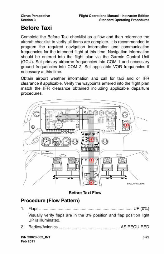
Cirrus Perspective Flight Operations Manual - Instructor EditionSection 3 Standard Operating Procedures
P/N 23020-002_INT 3-29
Before TaxiComplete the Before Taxi checklist as a flow and than reference theaircraft checklist to verify all items are complete. It is recommended toprogram the required navigation information and communicationfrequencies for the intended flight at this time. Navigation informationshould be entered into the flight plan via the Garmin Control Unit(GCU). Set primary airborne frequencies into COM 1 and necessaryground frequencies into COM 2. Set applicable VOR frequencies ifnecessary at this time.
Obtain airport weather information and call for taxi and or IFRclearance if applicable. Verify the waypoints entered into the flight planmatch the IFR clearance obtained including applicable departureprocedures.
Procedure (Flow Pattern)
1. Flaps ................................................................................. UP (0%)
Visually verify flaps are in the 0% position and flap position lightUP is illuminated.
2. Radios/Avionics ..................................................... AS REQUIRED
Before Taxi Flow
SR22_OP02_2941
Feb 2011

3-30 P/N 23020-002_INT
Flight Operations Manual - Instructor Edition Cirrus PerspectiveStandard Operating Procedures Section 3
Ensure all radios and avionics are programmed, navigationfrequencies identified, courses set and with required waypoints orflight plans loaded.
3. Cabin Heat/Defrost ................................................ AS REQUIRED
4. Fuel Selector ...........................................................SWITCH TANK
Switch tank to ensure positive fuel flow from both fuel tanks.
Avionics Configuration
• Audio Panel.....................................Select COM AS REQUIRED
Ensure desired communication are selected. Adjust intercomvolume as required.
• Autopilot ......................................................................Verify OFF
Verify the autopilot is not engaged and yaw damper is off.
• GCU/MFD/PFD................... SET COM and FPL AS REQUIRED
Initialize the MFD and verify database currency. Construct flightplan as required and set applicable communication andnavigation frequencies.
• MFD ....................................................................... CONFIGURE
Adjust MAP page range to display Safe Taxi. Select Chartviewto view the airport diagram if Safetaxi in not available for theairport.
• PFD..................................................................VERIFY and SET
Verify PFD is fully aligned and select the traffic display on PFDinset display.
Instructor Notes
The checklist item ‘Radios/Avionics’ should prompt the pilot to set upall communication frequencies and flight plan for departure. It is verycommon for pilots to check off this item quickly and not perform anyradio or avionics related tasks.
For IFR departures, encourage pilots to obtain their IFR clearanceseparately, and before obtaining a taxi clearance. This will ensurethere is adequate time to program navigation and communicationinformation before taxi.
There are multiple ways to set and control communication frequencies,including PFD controls, GCU controls, and auto-fill features. The mostbasic and intuitive control is the dedicated communication controls
Feb 2011

Cirrus Perspective Flight Operations Manual - Instructor EditionSection 3 Standard Operating Procedures
P/N 23020-002_INT 3-31
located on the PFD bezel. Pilots new to the Perspective avionics willquickly learn to use these controls. Encourage pilots to use the GCUand auto-fill communication controls only after the pilot is comfortablewith the GCU and the dual concentric knob.
As a general rule of thumb, communication frequencies for departureshould be organized in the following order:
• Com 1- Tower and Departure
• Com 2- ATIS, Ground, Clearance Delivery
Pilots are encouraged to always input navigation waypoints into theflight plan even for basic VFR flights. Doing so will allow the pilot totake advantage of VNAV functionality and will allow for easier coursechanges if necessary enroute. VFR pilots who are familiar with theflight planning controls and indications will adapt to IFR training andflying more quickly. Also, using the flight plan feature instead of direct-to navigation allows for a quick change in navigation if a return to thedeparture airport is necessary.
Common Errors
• Neglects to setup communication and navigation informationbefore taxi. Programming errors or delays typically occur whenthese tasks are completed at the end of the runway beforetakeoff,
• Fails to switch fuel tanks,
• Fails to reference the electronic checklist,
• Fails to deselect a monitored frequency on the audio panel afterobtaining the necessary information, typically ATIS/AWOS.
Feb 2011

3-32 P/N 23020-002_INT
Flight Operations Manual - Instructor Edition Cirrus PerspectiveStandard Operating Procedures Section 3
Taxi-OutA cause of brake failure is the creation of excessive heat throughimproper braking practices. Riding the brakes while taxiing causes acontinuous build up of energy which may lead to excessive heat.Excessive heat causes warped brake rotors, damaged or glazedlinings, damaged o-rings, and vaporized brake fluid. To avoid brakefailure, observe the following operating and maintenance practices:
• Directional control should be maintained with rudder deflectionsupplemented with brake pressure as required,
• Use only as much power (throttle) as is necessary to achieveforward movement. 1000 RPM is enough to maintain forwardmovement under normal conditions,
• Avoid unnecessary high speed taxiing. High speed taxiing willresult in excessive demands on the brakes, increased brakewear, and the possibility of brake failure,
• Use the minimum necessary brake application to achievedirectional control,
• Do not ride the brakes. Pilots should consciously removepressure from the brakes while taxiing. Failure to do so results inexcessive heat, premature brake wear, and increased possibilityof brake failure,
• Refer to the Handling, Service and Maintenance section of thePOH or the Maintenance manual for recommendedmaintenance and inspection intervals for brakes.
Maintain high levels of situational awareness during all movement onthe airport surface to avoid a runway incursion accidents. Minimizetasks such as reading checklists or folding maps while taxiing. Utilizethe Safe Taxi airport diagram to aid in situational awareness.
• WARNING •
Maximum continuous engine speed for taxiing is 1000 RPMon flat, smooth, hard surfaces. Power settings slightly above1000 RPM are permissible to start motion, for turf, softsurfaces, and on inclines. Use minimum power to maintain taxispeed.
Feb 2011

Cirrus Perspective Flight Operations Manual - Instructor EditionSection 3 Standard Operating Procedures
P/N 23020-002_INT 3-33
Procedure (Flow Pattern)
1. Parking Brake ............................................................DISENGAGE
Manually depress parking brake and ensure completely down.
2. Brakes................................................................................ CHECK
Upon initial movement verify both brakes are functioning byapplying pressure.
3. HSI Orientation .................................................................. CHECK
Visually check HSI alignment with magnetic compass.
4. Attitude Gyro...................................................................... CHECK
Verify gyro is erect and horizon bars are set level.
5. Turn Coordinator ................................................................ CHECK
During turns on the ground, verify the rate of turn indicatordisplays a turn in the direction of the turn and inclinometerdisplays a skid.
Taxi-Out Flow
SR22_OP02_2942
Feb 2011

3-34 P/N 23020-002_INT
Flight Operations Manual - Instructor Edition Cirrus PerspectiveStandard Operating Procedures Section 3
Instructor Notes
Brake fires and premature brake wear are preventable by adhering toproper braking practices. The following are indications of improperbraking techniques being used by the pilot:
• Continuous power above 1000 RPMs is required for forwardmovement,
• Aircraft speed over the ground is too slow considering engineRPM,
• Aircraft darting or over controlling during straight taxi resultingfrom the aircraft being steered via brakes, not rudder,
• Pilot does not reduce power to slow or stop the aircraft,
• Pilot taxis too fast which results in excess braking to stop.
The indications of a failed digital instrument in the Perspective systemshould be very apparent to the pilot. However, this does not reduce theimportance of a proper instrument check while the aircraft is beingtaxied. Make sure the pilot cross references all instrumentation,including standby instruments during the taxi, especially in preparationfor IFR flight.
Ensure pilots develop a habit of setting and cross referencing thestandby altimeter whenever the barometric pressure is set on the PFD.
Common Errors
• Improper braking technique resulting in premature wear andpossible fire,
• Fails to set and check all instrumentation during taxi or when theaircraft is moving and turning on the ground,
• Fails to reference the taxiing checklist,
• Fails to reference Safe Taxi for situational awareness duringground operations.
Feb 2011

Cirrus Perspective Flight Operations Manual - Instructor EditionSection 3 Standard Operating Procedures
P/N 23020-002_INT 3-35
Before TakeoffComplete the Before Takeoff checklist as a do-list. Complete thechecklist at an appropriate run up area prior to departure. The BeforeTakeoff checklist will ensure the aircraft is properly configured fortakeoff and all engine and electrical indications are within parameters.Run-up items are included in this checklist. Verify engine oiltemperature reaches a minimum of 100º F prior to applying run uppower settings. Verify all engine and electrical indications are normalprior to departure.
During cold weather operations, the engine should be properlywarmed before takeoff. In most cases this is accomplished when theoil temperature has reached at least 100º F. In warm or hot weather,precautions should be taken to avoid overheating during prolongedground engine operation. Additionally, long periods of idling may causefouled spark plugs.
Procedure (Do-List)
1. Doors ..............................................................................LATCHED
Verify both top and bottom latch of each door is securely latched.Press firmly at each door latch position to determine the securityof each door.
2. CAPS Handle................................................Verify Pin REMOVED
Verify the CAPS pin is removed and stowed. Ensure cover placardis securely fastened.
3. Seat Belts and Shoulder Harness.................................... SECURE
Verify the security and placement of all seat belts and shoulderharnesses of each occupant. Also, verify all occupants areproperly informed of seat belt requirements and operation.
4. Fuel Quantity ................................................................. CONFIRM
Confirm the fuel quantity is sufficient for the planned flight and fueltank quantities are balanced.
5. Fuel Selector......................................................... FULLEST TANK
Ensure the fuel selector is drawing fuel from the fullest tank.
6. Fuel Pump ............................................................. AS REQUIRED
SR20/SR22 - Fuel Pump On
SR22TN/SR22T - Fuel Pump Low Boost
Feb 2011

3-36 P/N 23020-002_INT
Flight Operations Manual - Instructor Edition Cirrus PerspectiveStandard Operating Procedures Section 3
7. Mixture ................................................................... AS REQUIRED
SR22 - Set the mixture full rich for sea level departures. Setmixture control lever for maximum power on takeoff for altitudeshigher then sea level. Reference the Max Power Fuel Flow placardor the top of the green arc of the fuel flow gauge for proper mixturesetting. Power must be at full-throttle for placarded values to beaccurate.
SR20/SR22TN/SR22T - Set the mixture full rich for all altitudes.
8. Flaps ...............................................................SET 50% & CHECK
Select flaps to 50% and visually verify both flaps are in positionprior to takeoff.
9. Transponder .............................................................................SET
Set assigned squawk code if one is given, otherwise, set theappropriate code.
10. Autopilot ............................................................................. CHECK
Complete the autopilot test in accordance with the autopilot userguide.
11. Navigation Radios/GPS ...........................................Set for Takeoff
Verify radio frequencies are set, to include tower/departurefrequencies. Check GPS flight plan for accuracy and correct initialwaypoint.
12. Cabin Heat/Defrost ................................................ AS REQUIRED
Set environmental controls as desired prior to takeoff.
13. Brakes ...................................................................................HOLD
Firmly hold brakes. Set the parking brake if assistance is required.
14. Power Lever ...................................................................1700 RPM
Increase power lever to 1700 RPM for engine run-up. Ensure oiltemperature is at least 100º F prior to increasing power. Select theengine page for expanded engine and electrical information duringthe engine run-up.
15. Alternator ........................................................................... CHECK
Alternator will be checked by placing greater electrical loads andturning on additional equipment below.
a. Pitot Heat............................................................................ ON
b. Navigation Lights ................................................................ ON
Feb 2011

Cirrus Perspective Flight Operations Manual - Instructor EditionSection 3 Standard Operating Procedures
P/N 23020-002_INT 3-37
c. Landing Light.......................................................................ON
d. Annunciator Lights...................................................Verify OFF
Verify that no electrical CAS messages appear on the PFD andthat positive amps are indicated.
16. Voltage ............................................................................... CHECK
Verify voltage outputs for both main buses and the essential busare in the green arcs.
17. Pitot Heat ............................................................... AS REQUIRED
Pitot heat should be turned ON for flight into IMC, flight into visiblemoisture, or whenever ambient temperatures are 5º C or less toreduce the possibility of pitot tube icing.
18. Navigation Lights ................................................... AS REQUIRED
Select navigation lights ON for night operations.
19. Landing Light ......................................................... AS REQUIRED
Select landing light ON. It is recommended to leave the landinglight on while within 10NM of the departure airport.
20. Magnetos .............................................. CHECK LEFT and RIGHT
a. Ignition Switch ..................................R, note RPM, then BOTH
b. Ignition Switch .................................. L, note RPM, then BOTH
RPM drop must not exceed 150 RPM for either magneto. RPMdifferential must not exceed 75 RPM between magnetos. If there isa doubt concerning operation of the ignition system, RPM checksat higher engine speeds will usually confirm whether a deficiencyexists. An absence of RPM drop may indicate faulty grounding ofone side of the ignition system or magneto timing set in advanceof the specified setting.
21. Engine Parameters ............................................................ CHECK
Visually verify all engine parameters are in acceptable ranges.Check Oil pressure and temperature, RPM, manifold pressure,EGT and CHT.
22. Power Lever ................................................................... 1000 RPM
23. Flight Instruments, HSI and Altimeter ................. CHECK and SET
Set all flight instruments for initial course and altitude. Verify theHSI displays proper course and heading when checked with
Feb 2011

3-38 P/N 23020-002_INT
Flight Operations Manual - Instructor Edition Cirrus PerspectiveStandard Operating Procedures Section 3
magnetic compass. Ensure local altimeter has been set and iswithin 75 feet of field elevation.
24. Flight Controls ................................................. FREE & CORRECT
Check for full range of motion of the control yoke and that controlsurface deflection corresponds to yoke deflection.
25. Trim ........................................................................ SET for Takeoff
Set electric trim in the takeoff position as displayed on control yokearm.
26. Autopilot .................................................................. DISCONNECT
Ensure PFD heading and altitude bugs are set and the autopilot isdisconnected.
GFC 700 - Press the go-around button on the throttle to engagethe Flight Director in Takeoff (TO) mode. Set the HDG and ALTbug for the assigned initial heading and altitude.
Icing Conditions Anticipated after Takeoff (FIKI):
1. ICE PROTECT System Switch.................................................. ON
2. ICE PROTECT Mode Switch......................................NORM/HIGH
HIGH should be selected initially to ensure critical lifting surfacesremain clear of ice during takeoff and initial climb. Once in enrouteclimb and ice buildup on unprotected surfaces is negligible, thepilot may select NORM. If rate of ice buildup on protected surfacesis unacceptable, select HIGH or MAX as appropriate.
3. PITOT HEAT Switch .................................................................. ON
4. Cabin Heat ................................................................................ Hot
5. Windshield Defrost .................................................................... ON
Hot windshield defrost should be used to reduce the possibility ofice forming on the windshield.
6. Ice-Inspection Lights ................................................... As Required
Ice inspection lights will illuminate the leading edges of the wingsand horizontal stabilizer in order to monitor ice accumulation andconfirm fluid flow at night.
Instructor Notes
When possible, the Before Takeoff checklist should be completed atthe end of the runway or in a designated run-up area. Checklist items
Feb 2011
Cirrus Perspective Flight Operations Manual - Instructor EditionSection 3 Standard Operating Procedures
P/N 23020-002_INT 3-39
that are intentionally not completed due to further taxiing requirementsor extended run-up periods on the ground should not be checked off inthe electronic checklist until they are actually completed before takeoff.For example, a pilot may elect to leave the flaps at 0% for further taxiover contaminated surfaces. Reference the checklist at the end of therunway to ensure all remaining controls are properly set for takeoff.
The run-up items in the Before Takeoff checklist should be completedas a flow with the engine monitoring page displayed on the MFD. Thisallows the pilot to see more detailed engine and electrical information.Return to the checklist page to verify all items are completed. Inaddition to completing the Before Takeoff checklist in its entirety, it isalso recommended to teach a quick pre-takeoff checklist flow to beaccomplished immediately before the departure roll. A quick sweepthrough the cockpit to re-check the boost pump setting, mixturesetting, flap setting, lights, pitot heat, and trim is a good habit todevelop.
Encourage pilots to set the flight director command bars in the takeoffmode for initial climb reference and for reduction of autopilotprogramming errors. Regardless of the time of year, pilots transitioninginto a Cirrus aircraft equipped with the FIKI system should bepresented with a departure into known icing conditions scenario.Ensure pilots follow the procedure detailed in the checklist and confirmflow coverage over the protected surfaces. Verify that pilots also turnon the pitot heat prior to departure and abide by pitot heat groundlimitations.
Encourage pilots to monitor CTAF or tower frequency at the end of therunway to develop a mental picture of traffic in the local area.
Common Errors
• Fails to complete checklist items in their entirety,
• Intentionally skips items in the checklist but neglects to re-reference the checklist and complete the task before departure,
• Fails to adhere to FIKI pitot heat ground operating limitations,
• Fails to recognize an unlatched pilot or passenger door duringthe engine run-up.
Feb 2011

3-40 P/N 23020-002_INT
Flight Operations Manual - Instructor Edition Cirrus PerspectiveStandard Operating Procedures Section 3
Takeoff BriefingReference the Takeoff checklist prior to departure. Complete a takeoffbriefing to review the critical items prior to takeoff. A takeoff briefingallows the pilot to review the takeoff procedure and determine theactions necessary in the event of abnormal/emergency conditionsduring the takeoff roll and initial climb. At a minimum, a takeoff briefingshould include the following items:
• Type of procedure used (normal, short, or soft),
• Takeoff distance required / runway distance available,
• VR and initial climb speed,
• Abnormality / engine failure before VR,
• Abnormality / engine failure after VR,
• CAPS option in the event of a loss of power during climboutconsidering altitude.
Sample Takeoff Briefing
This will be a __________ (normal, short, soft) takeoff from runway_________ with a takeoff distance of _______ feet and ________ feetof runway available. Rotation speed is ______ KIAS. Initial headingafter takeoff is _______ degrees to an altitude of _______ feet. Abortthe takeoff for any engine failures/abnormalities prior to rotation. If theengine fails after rotation I will ______________(determine if CAPS isan option).
Feb 2011

Cirrus Perspective Flight Operations Manual - Instructor EditionSection 3 Standard Operating Procedures
P/N 23020-002_INT 3-41
Normal TakeoffUse of the Flight Director in Takeoff (TO) mode is recommended ifusing the GFC 700 autopilot. Press the Go-around button on thethrottle to engage the Flight Director in TO mode. The recommendedflap setting for a normal takeoff is 50%. Align the aircraft on the runwaycenterline and smoothly apply full power in a 4 to 5 second continuoussweep. Slight brake pressure may be required for directional controlearly in the takeoff roll in some crosswind situations. Maintaindirectional control with rudder during the takeoff roll after sufficientrudder control is available. Check engine and airspeed indicationsearly in the takeoff roll to ensure proper function. Discontinue thetakeoff by reducing the power to idle and using brakes as necessaryfor any abnormal engine or airspeed indications, sluggish acceleration,or rough engine. At VR smoothly apply back pressure to the controlyoke sufficiently enough to rotate the aircraft. Pitch the aircraft forapproximately 7º to intercept VX or VY as appropriate. Maintaincoordination with proper rudder input during the climb out.
Procedure (Flow Pattern)
1. Brakes............................................ RELEASE (Steer with Rudder)
Initially, a slight amount of differential braking may be required fordirectional control. As airspeed increases, both feet should beremoved from toe brakes and directional control maintained withrudder inputs.
2. Power Lever ........................................................FULL FORWARD
Smoothly increase power lever full forward for maximum takeoffpower. Discontinue takeoff if any rough or sluggish acceleration isnoted. Do not confuse any detents for a full power setting. Enginespeed at full power should be approximately:
• SR20/SR22/SR22TN - 2700 RPM,
• SR22T - 2500 RPM.
SR22TN/SR22T - During the first takeoff of the day, due torelatively low engine oil temperature, engine Manifold Pressuremay exceed limits. This is acceptable, but if this occurs, pilotsshould smoothly reduce power slightly to bring MP back belowred-line. As a technique, pilots can smoothly add power on takeoffuntil reaching red line, instead of full-forward. Very that the powerlever can be moved to full forward and remain within limits.
Feb 2011

3-42 P/N 23020-002_INT
Flight Operations Manual - Instructor Edition Cirrus PerspectiveStandard Operating Procedures Section 3
3. Engine Parameters ............................................................ CHECK
Monitor engine parameters during the takeoff roll. If any abnormalor questionable indications arise, abort the takeoff early in thetakeoff roll.
4. Elevator Control .......................................ROTATE Smoothly at VR
As airspeed approaches VR, smoothly and gradually apply backpressure to the control yoke to increase the angle of attacksufficiently enough to rotate the aircraft.
VR (SR20) 65-70 KIAS
VR (SR22) 70-73 KIAS
5. Flaps ..........................................................................................UP
Retract the flaps after the following conditions have been met.Slight back pressure may be required after flap retraction
• SR20 - 85 KIAS,
• SR22 - 80 KIAS,
• Positive rate of climb,
• Clear of terrain and obstacles.
• FIKI - Retract as soon as practical once conditions are met.
Instructor Notes
Pilots learning to fly an SR22 after flying a lower-powered aircraft aretypically caught off guard by the amount of acceleration, left turningtendencies, and climb rates. Pilots may have difficulty early in thetakeoff roll when switching from steering with brakes to steering withrudder controls. Follow these recommendations for addressing thesepilot issues.
• Thoroughly describe the takeoff experience and desired controlinputs, including magnitude of control inputs,
• Use a wide runway, 75 feet or greater, for initial takeoff practiceto increase safety margins. Eventually, practice on a narrowerrunway,
• Avoid rolling takeoffs,
• Ensure the pilot is focusing his or her vision at the opposite endof the runway to help identify small deviations sooner,
Feb 2011
Cirrus Perspective Flight Operations Manual - Instructor EditionSection 3 Standard Operating Procedures
P/N 23020-002_INT 3-43
• Instruct the pilot to add power at half the rate of normal poweraddition (8-10 seconds from 0 to 100%). Ensure adequaterunway is available for this procedure,
• Instruct the pilot to add 50% power while holding brakes, checkgauges, then release brakes and steer with rudder only. Thishelps pilots make the transition from brake steering to ruddersteering,
• Ensure the pilot can quickly scan airspeed during the takeoff rolland verify that the majority of his or her time is spent lookingoutside the aircraft.
Based upon the experience level of the pilot and proficiency observedduring taxi, it may be beneficial for the instructor to demonstrate thefirst takeoff. Have the pilot follow along with the controls. Emphasizeproper control inputs for rotation, proper rudder inputs, and deck anglefor initial climb.
Completion Standards
• Verifies sufficient runway length is available for departure,
• For IFR flights, becomes familiar with and follows departureprocedure guidance,
• Selects and executes the proper takeoff procedure with theappropriate configuration,
• Briefs the takeoff as recommended in this section with emphasison developing a plan to handle abnormalities before or afterrotation including CAPS procedures,
• Adds power smoothly to full power (4 to 5 seconds from 0 -100%) and verbally verifies engine indications, CAS messages,and airspeed are normal early in takeoff roll,
• Aborts the takeoff early in the takeoff roll and applies brakes asnecessary for engine parameter exceedences, CAS messages,airspeed issues, or other safety of flight issues,
• Keeps the runway center line between the main landing gearwheels through takeoff roll, rotation, and initial climb,
• Rotates smoothly at the recommended rotation speed to a climbattitude that will intercept VX or VY as desired,
• Retracts flaps as recommended and continues to pitch theaircraft for the recommended climb airspeed,
Feb 2011

3-44 P/N 23020-002_INT
Flight Operations Manual - Instructor Edition Cirrus PerspectiveStandard Operating Procedures Section 3
• Does not engage the autopilot before 400 feet AGL,
• Maintains runway alignment until 1/2 mile past the departureend of the runway unless otherwise directed by ATC.
Common Errors
• Loses directional control due to inadequate rudder inputs,
• Fails to recognize an unlatched or improperly closed door,
• Fails to promptly add full power early in the takeoff roll,
• Over rotates and uses poor airspeed control during the initialclimb,
• Fails to track over the extended runway centerline during initialclimb,
• Uses brakes excessively during the takeoff roll,
• Fails to recognize an unsafe situation early in the takeoff roll andfails to abort the takeoff promptly.
Feb 2011

Cirrus Perspective Flight Operations Manual - Instructor EditionSection 3 Standard Operating Procedures
P/N 23020-002_INT 3-45
Figure 3-1Takeoff Profile
SR
22_O
P02
_266
2
Dep
artu
re R
oll
Ful
l Pow
erA
irspe
ed/E
ngin
e M
onito
r
Rot
ate
Intit
ial C
limb
Pitc
h 7.
0° -
10°
-
Inte
rcep
t Vx
or V
y as
app
ropr
iate
Fla
ps r
etra
ct
- C
lear
of t
erra
in
- P
ositi
ve R
ate
of C
limb
Aft
er 1
000’
AG
LE
stab
lish
Cru
ise
Clim
bC
ompl
ete
Clim
b C
heck
list
Feb 2011
3-46 P/N 23020-002_INT
Flight Operations Manual - Instructor Edition Cirrus PerspectiveStandard Operating Procedures Section 3
Short-Field TakeoffUse the short-field technique to maximize takeoff performance andminimize takeoff ground roll. Set Flaps to 50% for a short-field takeoff.Align the aircraft on the runway centerline as close as possible to theend of the runway. Apply sufficient brake pressure and smoothly applyfull power. Check engine indications and ensure full power beforereleasing the brakes. Steer with rudder only in order to minimize theground roll distance. Rotate the aircraft at VR smoothly and pitch forthe obstacle clearance speed if an obstacle is present. Pitch for VYafter clearing obstacles.
1. Flaps ........................................................................................50%
Set flaps to 50% and visually verify both flaps are in position priorto takeoff.
2. Brakes ...................................................................................HOLD
Hold brakes firmly, do not allow the aircraft to roll.
3. Power Lever ........................................................FULL FORWARD
Smoothly increase power lever full forward for maximum takeoffpower. Discontinue takeoff if any rough or sluggish acceleration isnoted. Do not confuse any detents for a full power setting. Enginespeed at full power should be approximately:
• SR20/SR22/SR22TN - 2700 RPM,
• SR22T - 2500 RPM.
4. Mixture .....................................................................................SET
SR22 - Set the mixture full rich for sea-level departures. Setmixture control lever for maximum power on takeoff for altitudeshigher then sea level. Reference the Max Power Fuel Flow placardor the top of the green arc of the fuel flow gauge for proper mixturesetting. Power must be at full-throttle for placarded values to beaccurate.
SR20/SR22TN/SR22T - Set the mixture to full rich for all altitudes.
5. Engine Parameters ............................................................ CHECK
Check all engine parameters prior to releasing the brakes. If anyabnormal or questionable indications arise, consider abortingtakeoff.
6. Brakes ............................................................................ RELEASE
Feb 2011

Cirrus Perspective Flight Operations Manual - Instructor EditionSection 3 Standard Operating Procedures
P/N 23020-002_INT 3-47
Release the brakes and steer with rudder only. Sufficient ruddercontrol should be available with full power.
7. Elevator Control ....................................... ROTATE Smoothly at VR
As airspeed approaches VR, smoothly and gradually apply backpressure to the control yoke to increase the angle of attacksufficient for rotation.
VR (SR20) - 65 KIAS
VR (SR22) - 70 KIAS
8. Airspeed at Obstacle ........................... Obstacle Clearance Speed
Maintain the obstacle clearance speed with flaps at 50% untilsafely clear of all obstacles.
SR20 obstacle clearance speed - 77 KIAS
SR22 obstacle clearance speed - 78 KIAS
Instructor Notes
Pilots should be able to perform a normal takeoff as described in thecompletion standards before attempting a short-field takeoff. Use theShort-field Takeoff checklist to brief the takeoff procedure.
As always in a critical phase of flight, instructors should maintain closedefensive positioning on rudder pedals, throttle, and flight controls.Watch for over rotation, excessive climb angles, stall conditions, anduncoordinated flight.
Obstacles may be simulated by requiring the pilot to climb at Vx untilverbally announcing clear of obstacles. Closely monitor the pilot toverify flaps are not retracted prematurely, causing an excessive sinkrate.
Completion Standards
• Properly executes applicable completion standards for a normaltakeoff,
• Uses maximum available runway,
• Applies full power while holding sufficient brake pressure tokeep the aircraft stationary until,
• Rotates promptly at the desired airspeed to proper pitch attitudeto intercept Vx or Vy as necessary,
• Maintains coordination throughout initial climb.
Feb 2011

3-48 P/N 23020-002_INT
Flight Operations Manual - Instructor Edition Cirrus PerspectiveStandard Operating Procedures Section 3
Common Errors
• Fails to use all available runway,
• Fails to hold sufficient brake pressure to keep the aircraftstationary during power addition,
• Over rotates the aircraft, causing a possible stall condition,
• Fails to apply adequate rudder inputs to maintain coordination,
• Prematurely retracts flaps, causing excessive sink rates.
Feb 2011

Cirrus Perspective Flight Operations Manual - Instructor EditionSection 3 Standard Operating Procedures
P/N 23020-002_INT 3-49
Soft-Field TakeoffSoft or rough field takeoffs are executed using 50% flaps. Add 20% tothe takeoff ground roll distance for dry grass runways and 30% for wetgrass. Ensure the quality of the runway is adequate to support theaircraft. Avoid runways with long grass, soggy soil and large ruts orholes. Higher power settings will be required to taxi on grass surfaces.Hold full back pressure on the control yoke while taxiing and during theinitial takeoff roll to reduce the pressure on the nose wheel. Reducethe back pressure slightly once the nose wheel lifts off the ground.Hold the aircraft in a nose up attitude until the aircraft becomesairborne. Once airborne reduce back pressure as necessary to remainin ground effect or within 20 feet of the surface. Accelerate the aircraftto VX (for obstacles clearance) or VY before climbing out of groundeffect.
Instructor Notes
Occasionally, pilots flying Cirrus aircraft will have a need to fly into andout of grass or soft field airports. The soft field technique may also beused when departing a rough or contaminated runway surface.
Have the pilot demonstrate proficiency performing the soft fieldtechnique on a hard surface runway before attempting at an actualgrass field.
Completion Standards
• Properly executes applicable completion standards for a normaltakeoff,
• Verifies the runway condition supports safe takeoff by taxiingover the runway prior to depart,
• Holds the elevator full aft during taxi and takeoff roll whensufficient elevator authority exists,
• Holds the aircraft at a high angle (approx 5 to 7.5 degrees) whensufficient airflow is available over the elevator,
• Relaxes back pressure during the takeoff roll and does not overrotate the aircraft,
• Reduces pitch when the aircraft becomes airborne to maintainin ground effect until VX or VY is reached,
• Climbs out at VXor VY as necessary.
Feb 2011

3-50 P/N 23020-002_INT
Flight Operations Manual - Instructor Edition Cirrus PerspectiveStandard Operating Procedures Section 3
Common Errors
• Fails to apply sufficient back pressure during taxi or takeoff roll,
• Over rotates the aircraft during the takeoff roll or at rotation,
• Fails to apply sufficient rudder input to maintain directionalcontrol,
• Climbs out of ground effect too quickly.
Crosswind Takeoff TechniquePartially deflect the ailerons into the wind during a crosswind takeoff.Maintain directional control with proper rudder input. Allow the aircraftto accelerate to a speed slightly higher then VR prior to rotation. Liftthe aircraft off the ground slightly quicker than with a normal takeoff.Shortly after rotation, crab the aircraft into the wind to track the aircraftalong the runway centerline. Maintain coordination during climb withproper rudder input.
Instructor Notes
Do not overlook the importance of performing a crosswind takeoffcorrectly. When planning an instructional activity, look for airports withrunway configurations that have crosswind conditions for takeoff andlanding practice.
Reference the Envelope of Safety for suggested maximum headwindand crosswind values based upon pilot experience. Exceeding one’scapability to handle crosswinds is a common contributor to manytakeoff and landing accidents.
Completion Standards
• Properly executes applicable completion standards for a normaltakeoff,
• Recognizes the need for the crosswind technique,
• Applies aileron input into the crosswind and uses rudder tomaintain runway alignment during the takeoff roll and rotation,
• Reduces the amount of aileron deflection as the aircraftaccelerates and aileron control effectiveness increases,
• Establishes coordinated flight and a wind correction angleshortly after takeoff and tracks over the runway centerline duringinitial climb.
Feb 2011

Cirrus Perspective Flight Operations Manual - Instructor EditionSection 3 Standard Operating Procedures
P/N 23020-002_INT 3-51
Common Errors
• Fails to identify a crosswind situation,
• Fails to apply correct aileron inputs resulting in drift or side loadson the landing gear,
• Fails to establish a wind correction angle after rotation andallows the aircraft to drift away from the runway center line,
• Fails to resume coordinated flight after rotation resulting in across-control situation,
Feb 2011

3-52 P/N 23020-002_INT
Flight Operations Manual - Instructor Edition Cirrus PerspectiveStandard Operating Procedures Section 3
Enroute ClimbComplete the Climb checklist as a flow when time and workloadpermit. Once clear of obstacles and terrain, normal climbs areperformed flaps UP (0%) and full power at speeds 5 to 10 knots higherthan best rate-of-climb speeds. These higher speeds give the bestcombination of performance, visibility and engine cooling. Whendesired and clear of obstacles, transition to cruise climb speed forincreased engine cooling, visibility, and passenger comfort.
For maximum rate of climb, use the best rate-of-climb speeds shownin the rate-of-climb chart in Section 5 of the POH. If an obstructiondictates the use of a steep climb angle, the best angle-of-climb speedshould be used. Climbs at speeds lower than the best rate-of-climbspeed should be of short durations to avoid engine cooling problems.
For operation in noise sensitive areas when obstacle and terrainclearance is not an issue, the following procedures are recommended.Upon reaching 1000' AGL reduce power to 2500 RPM with maximummanifold pressure. Adjust pitch to maintain the desired climb airspeed.Resume full power climb upon reaching 3000' AGL and adjust mixtureaccordingly.
• Caution •
Use caution when engaging the autopilot at low altitude due tothe increased workload of programming the autopilot andpotential for human errors. Pilots should hand fly the aircraft toa safe altitude and engage the autopilot if desired when timeand workload permit.
Climb Speeds (KIAS) SR20 SR22 SR22TN/SR22T
Cruise Climb 100-110 110-120 120-130
Best Rate (VY), Sea Level 96 101 101
Best Rate (VY), 10,000 ft 92 96 101
Best Angle (VX), Sea Level 83 79 84
Best Angle (VX), 10,000 ft 87 83 84
Feb 2011
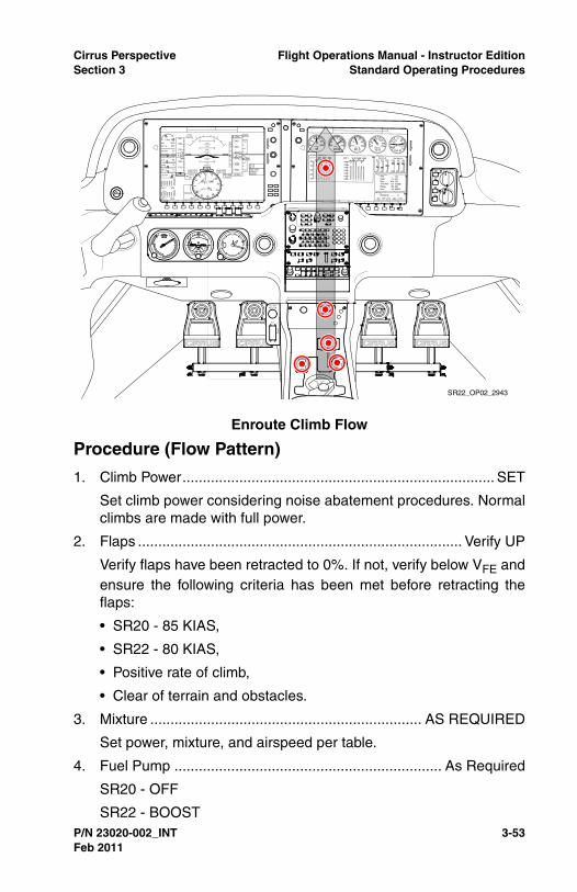
Cirrus Perspective Flight Operations Manual - Instructor EditionSection 3 Standard Operating Procedures
P/N 23020-002_INT 3-53
Procedure (Flow Pattern)
1. Climb Power............................................................................. SET
Set climb power considering noise abatement procedures. Normalclimbs are made with full power.
2. Flaps ................................................................................ Verify UP
Verify flaps have been retracted to 0%. If not, verify below VFE andensure the following criteria has been met before retracting theflaps:
• SR20 - 85 KIAS,
• SR22 - 80 KIAS,
• Positive rate of climb,
• Clear of terrain and obstacles.
3. Mixture ................................................................... AS REQUIRED
Set power, mixture, and airspeed per table.
4. Fuel Pump .................................................................. As Required
SR20 - OFF
SR22 - BOOST
Enroute Climb Flow
SR22_OP02_2943
Feb 2011

3-54 P/N 23020-002_INT
Flight Operations Manual - Instructor Edition Cirrus PerspectiveStandard Operating Procedures Section 3
SR22TN/SR22T - LOW BOOST
Fuel boost should be left on during takeoff and for climb asrequired for vapor suppression with hot or warm fuel.
5. Engine Parameters ............................................................ CHECK
Check all engine parameters for any abnormal indications thatmay indicate impending engine problems.
• Fuel Flow - Monitor per Climb Settings table above
• Cylinder Head Temperatures - Adjust fuel flow and/or airspeedto keep CHTs below:
• SR22T - 420º F,
• SR22TN - 380º F.
6. Oxygen................................................................... AS REQUIRED
a. Oxygen Masks/Cannulas..................................................DON
b. Oxygen System .................................................................. ON
c. Flow Rate .........................ADJUST for planned cruise altitude
d. Flowmeters and Quantity......................................... MONITOR
For optimal protection, pilots are encouraged to use supplementaloxygen above 10,000 feet during the day and above 5,000 feet atnight.
Climb Settings Power LeverMixture / Fuel Flow
Airspeed
SR20 Full Forward Full Rich 100-110
SR22Full Forward Top of Green
Arc110-120
SR22TN
Full Power Climb
Full Forward Full Rich 120-130
Lean of Peak Climb
Full Forward Cyan Target or Less
130
SR22T
Full Power Climb
Full Forward Within Green Arc
120-130
Lean of Peak Climb
30.5” MP Cyan Target or Less
130
Feb 2011

Cirrus Perspective Flight Operations Manual - Instructor EditionSection 3 Standard Operating Procedures
P/N 23020-002_INT 3-55
Cannulas are not approved above 18,000 feet MSL becausecannulas fail to deliver adequate levels of oxygen. Pilots must usea mask that is certified above 18,000 feet MSL when operatingabove FL180.
If using a pulse oximeter, adjust flow rate to keep oxygensaturation above 90%. Pilots are encouraged to use pulseoximeter and check saturation levels every 10 to 15 minutes.
Avionics Configuration
• Autopilot - Engage modes as desired above 400 feet AGL whentime and workload permit,
• MFD - Complete Climb Checklist, monitor map for situationalawareness,
• PFD - Monitor aircraft flight parameters and system status.
Instructor Notes
It is easy for pilots to develop an excessive reliance on the autopilotduring the climb phase. Although the autopilot is a great tool forworkload management and passenger comfort, it cannot take theplace of good airmanship skills. Pilots must demonstrate the ability tomanage the aircraft and associated systems, communication, andnavigation tasks during departure.
Encourage pilots to hand-fly every other departure in an effort tomaintain their hand-flying proficiency. IFR pilots experiencing highworkloads, typically associated with ATC clearance changes, shoulduse the autopilot while performing extensive avionics programming.
The IAS mode of the autopilot should be used during all climbs tomaximize aircraft performance and increase safety.
It is very common for pilots new to the aircraft or avionics to focusinside the aircraft instead of outside during VMC climbs. Pilots mustlearn to divide their attention between cockpit tasks, instrument scan,and looking outside for collision avoidance. Early in training,encourage pilots to look outside during climbs, maneuvers, anddescents to develop a sense of the Cirrus visual references for climb,level flight, and descents.
Completion Standards
• Maintains positive aircraft control,
Feb 2011

3-56 P/N 23020-002_INT
Flight Operations Manual - Instructor Edition Cirrus PerspectiveStandard Operating Procedures Section 3
• Retracts the flaps when climbing, clear of obstacles, and at theprescribed airspeed,
• Maintains desired airspeed within +10/-5 KIAS,
• Abides by local noise abatement procedures if applicable,
• Follows instrument departure procedures if applicable,
• Follows ATC instructions and clearances if applicable,
• Completes the Climb checklist as a flow and references thechecklist when workload permits,
• Manages engine temperatures through airspeed/pitch control,proper power and mixture settings as recommended by theAFM,
• At pilot’s discretion, uses the autopilot to reduce workload,
• Uses proper scanning techniques and Traffic Alert System forcollision avoidance,
• Uses supplemental oxygen at the appropriate time during theclimb,
• Maintains appropriate cloud clearances during VMC climbs,
• Operates FIKI system properly when flying through icingconditions during departure.
Common Errors
• Inability to maintain desired airspeed while hand flying,
• Over dependence on the autopilot for controlled flight,
• Engaging the autopilot before 400 feet AGL,
• Fails to engage the proper mode of the autopilot,
• Fails to complete Climb checklist items,
• Fails to divide attention and look outside during VFR climbs,
• Fails to become familiar with, program, or follow applicabledeparture procedures,
• Neglects to monitor engine parameters during climb,
• Fails to set mixture control as required during climb,
• Fails to abide by sterile cockpit rules during climbout,
• Fails to monitor for icing conditions.
Feb 2011

Cirrus Perspective Flight Operations Manual - Instructor EditionSection 3 Standard Operating Procedures
P/N 23020-002_INT 3-57
CruiseComplete the Cruise checklist as a flow when time and workloadpermit. Allow the aircraft to accelerate to cruise speeds before settingthe desired cruise power setting. Ensure adequate fuel reservesremain for the intended destination. Normal cruise power settings arebetween 55% - 85% power with mixture set for best power or besteconomy. Turbo aircraft will always cruise at best economy.
Engine Break-In
For engine break-in of normally-aspirated engines, cruise at aminimum of 75% best power until the engine has been operated for atleast 25 hours or until oil consumption stabilizes. Turbo aircraft may beoperated at best economy with a power setting greater than 75%during engine break-in. Operation at higher power will ensure properseating of the rings, and is applicable to new engines, and engines inservice following cylinder replacement or top overhaul of one or morecylinders.
Procedure (Flow Pattern)
1. Fuel Pump ................................................... OFF / AS REQUIRED
Cruise Flow
SR22_OP02_2944
Feb 2011
3-58 P/N 23020-002_INT
Flight Operations Manual - Instructor Edition Cirrus PerspectiveStandard Operating Procedures Section 3
The Fuel Pump may be used for vapor suppression in cruise.Vapor lock issues may be recognized by fluctuating EGTs, CHTsand fuel flows, and rough engine operation. Select BOOST orHIGH BOOST as appropriate if vapor lock is suspected.
2. Power Lever .............................................................................SET
Allow the aircraft to accelerate to cruise speeds before settingcruise power. Select the desired percent power considering range,endurance, and desired performance for the intended flight.
SR22TN - Reduce the power lever to 2500 RPM with maximumMP. If a lower power setting is desired to increase range/endurance, reduce the throttle to the desired percent power.
SR22T - Reduce power lever to 30.5” MP or less.
3. Mixture ............................................................... LEAN as required
SR20/SR22 - Use the Lean Assist feature on the MFD Enginepage to set the mixture control for Best Power or Best Economy.
SR22TN/SR22T - Set the fuel flow to the cyan target or less.
4. Engine Parameters ........................................................ MONITOR
Monitor all engine parameters for any abnormal indications thatmay indicate impending engine problems.
• SR22TN/SR22T - Lean Mixture to keep all CHTs below 420º F(SR22T) or 380º F (SR22TN). As an approximation, a 0.5 GPHreduction in fuel flow will reduce CHTs by 15º F.
5. Fuel Flow and Balance................................................... MONITOR
Check fuel flow gauge and ensure fuel balance is within 7.5gallons (SR20), 10 gallons (SR22).
Fuel BOOST must be used for switching from one tank to another.Failure to activate the Fuel Pump before transfer could result indelayed restart if the engine should quit due to fuel starvation.
Mixture Description Exhaust Gas Temperature
Best Power 75º F Rich of Peak EGT
Best Economy 50º F Lean of Peak EGT
Feb 2011

Cirrus Perspective Flight Operations Manual - Instructor EditionSection 3 Standard Operating Procedures
P/N 23020-002_INT 3-59
Icing Conditions (FIKI)Even with an aircraft that is certified to operate in known icingconditions, prolonged flight in icing conditions should be avoided.Pilots should use good pre-flight planning to choose a route andaltitude that will minimize time in icing conditions. If this is not possible,consider delaying or cancelling the flight. Pilots should always have anescape option in case of a system malfunction or severe iceencounter. This escape could be above or below the cloud layer orbelow the freezing level. Note that in some conditions the freezinglevel may be at the surface or below the MEA.
Pilots may generally escape the worst icing conditions in stratusclouds by making an altitude change of more than 3000 ft. While flyingthrough cumulus clouds, altitude changes may not be effective andlateral deviations may be necessary to escape the worst icingconditions.
During icing encounters in cruise, increase engine power to maintaincruise speed as ice accumulates on the unprotected areas and causesthe aircraft to slow down. Sacrifice altitude if necessary in order tomaintain safe flying speed.
The autopilot may be used in icing conditions. However, every 30minutes the autopilot should be disconnected to detect any out-of-trimconditions caused by ice buildup. If significant out-of-trim or otheranomalous conditions are detected, the autopilot should remain off forthe remainder of the icing encounter. When disconnecting theautopilot with ice accretions on the airplane, the pilot should be alertfor out-of-trim forces.
Ice Formation Determination
Typically, a leading edge with a small radius will collect ice morequickly than a leading edge with a large radius. To help monitorpossible ice accumulation, a thin metal tab is attached to the outboardend of the right-hand and left-hand stall strips. In some icingconditions this tab may be the first place that airframe ice accretion isnoticeable. Additionally, refer to other areas of the aircraft, such as thehorizontal tail and lower windscreen, to aid in determining if ice isaccreting to the aircraft.
• Caution •
Ice accumulations on protected areas are abnormal.
Feb 2011

3-60 P/N 23020-002_INT
Flight Operations Manual - Instructor Edition Cirrus PerspectiveStandard Operating Procedures Section 3
De-Icing Procedures
1. Pitot Heat .........................................................................Verify ON
2. Ice Protect System Switch ........................................................ ON
3. Ice Protect Mode Switch ........................................ AS REQUIRED
Select NORM or HIGH as conditions dictate.
If icing conditions are inadvertently encountered, press MAX toinitially dissipate ice accumulation, then select NORM or HIGH asrequired by ice accumulation.
4. WIND SHLD Push-Button ..............................PRESS As Required
Use the windshield ice protection when residual fluid that is slungoff of the propeller will not keep the windshield free of ice. Due tothe temporary reduction in visibility, do not use the windshieldsprayer within 30 seconds prior to landing.
5. Airspeed................Maintain 95-177 KIAS and less than 204 KTAS
Maintaining airspeed within this range will ensure proper pressuredistribution over the wings and effective anti-ice system operation.Adjust final approach airspeed to 95 KIAS with 50% flaps whenlanding with ice adhering to the aircraft.
6. Flaps ..........................................................................................UP
Keep flaps in the up position until required for landing. Limit flapextension for landing to 50%.
7. Ice Inspection Lights .............................................. AS REQUIRED
Ice inspection lights will illuminate the leading edges of the wingsand horizontal stabilizer in order to monitor ice accumulation andconfirm fluid flow at night.
8. Cabin Heat .............................................................................. HOT
9. Windshield Defrost .................................................................... ON
Windshield defrost set to hot will help to keep the windshield freeof ice.
10. Anti-ice Fluid Quantity .................................................... MONITOR
Ensure adequate quantity to complete flight.
11. Ice Accumulation............................................................ MONITOR
If ice accretion rate is higher than desired or ice is not shedding,select a higher mode of operation. If ice accretions do not shed,
Feb 2011
Cirrus Perspective Flight Operations Manual - Instructor EditionSection 3 Standard Operating Procedures
P/N 23020-002_INT 3-61
select PUMP BKUP and perform the Anti-Ice System FailureChecklist. Exit icing conditions immediately if ice cannot be shed.
Avionics Configuration
• Autopilot - Ensure correct modes are engaged if desired,
• GCU/Flight Plan - ensure proper navigation is set,
• MFD - Use Lean Assist to lean the mixture. Complete the CruiseChecklist,
• PFD - Monitor aircraft flight parameters and system status.
Instructor Notes
When planning instructional activities it is important to select legs withdistances that allow adequate cruise time to accomplish all cruiserelated tasks and training objectives. Training flights should have 15 -30 minutes of level cruise flight.
Pilots in training have a tendency to become exceedingly relaxedduring cruise. Occasionally, pilots neglect to accomplish basicdestination setup tasks such as: descent planning, frequencyselection, and airport familiarity without prompting.
To combat this tendency, ensure pilots monitor ETE to the destinationduring cruise as a reference for descent planning and other arrival-related tasks. Also, make it clear to pilots that they are expected tomanage the tasks without prompting from the instructor. Eventually,the pilot must perform all flight related tasks without prompting orquestioning. Allowing a pilot to arrive at an airport without havingplanned a descent usually creates a stressful situation and can be agood learning experience.
Use the cruise portion of a training flight to provide repetitive avionicsrelated tasks or to introduce scenarios or maneuvers required by thesyllabus. Allow pilots to make and execute PIC decisions for thescenarios presented. Allow pilots to see the consequences of poordecisions when possible, while never compromising safety of flight.
Completion Standards
• Allows the aircraft to accelerate before setting cruise power,
• Adheres to procedures described in the AFM for setting cruisepower and mixture controls,
• Completes Cruise checklist,
Feb 2011
3-62 P/N 23020-002_INT
Flight Operations Manual - Instructor Edition Cirrus PerspectiveStandard Operating Procedures Section 3
• Monitors engine parameters and manages accordingly,
• Establishes the aircraft on the intended course and altitude,
• Ensures adequate fuel reserves will be available when reachingthe destination, monitors fuel status throughout the flight,
• Monitors enroute and destination weather periodically,
• Plans arrival and descent before descent is required,
• Keeps the aircraft within fuel balance limitations,
• Monitors the physical state of passengers during cruise,especially important for flights above 10,000 feet MSL,
• Identifies situations that require an altitude or route change,such as: weather, airspace, and traffic,
• Maintains altitude +/-200 feet and headings +/-15 degrees.
Common Errors
• Exhibits tendencies toward complacency, and fails to monitorflight status, passengers, pilot fatigue, and weather.
• Forgets to plan descents and prepare for arrival,
• Fails to recognize an inadequate fuel quantity situation orexceed the maximum fuel imbalance,
• Fails to set the mixture throughout the descent properly.
Feb 2011
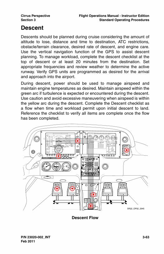
Cirrus Perspective Flight Operations Manual - Instructor EditionSection 3 Standard Operating Procedures
P/N 23020-002_INT 3-63
DescentDescents should be planned during cruise considering the amount ofaltitude to lose, distance and time to destination, ATC restrictions,obstacle/terrain clearance, desired rate of descent, and engine care.Use the vertical navigation function of the GPS to assist descentplanning. To manage workload, complete the descent checklist at thetop of descent or at least 20 minutes from the destination. Setappropriate frequencies and review weather to determine the activerunway. Verify GPS units are programmed as desired for the arrivaland approach into the airport.
During descent, power should be used to manage airspeed andmaintain engine temperatures as desired. Maintain airspeed within thegreen arc if turbulence is expected or encountered during the descent.Use caution and avoid excessive maneuvering when airspeed is withinthe yellow arc during the descent. Complete the Descent checklist asa flow when time and workload permit upon initial descent to land.Reference the checklist to verify all items are complete once the flowhas been completed.
Descent Flow
SR22_OP02_2945
Feb 2011

3-64 P/N 23020-002_INT
Flight Operations Manual - Instructor Edition Cirrus PerspectiveStandard Operating Procedures Section 3
Procedure (Flow Pattern)
1. Oxygen................................................................... AS REQUIRED
2. Altimeter ...................................................................................SET
Verify the proper altimeter setting has been set into the PFD and inthe standby altimeter.
3. Cabin Heat/Defrost ................................................ AS REQUIRED
4. Landing Light ............................................................................ ON
The landing light should be selected on for visibility to others at thetop of the descent or within 10NM from the destination. If in IMC,consider leaving off to reduce light reflection in the cabin.
5. Fuel System ....................................................................... CHECK
Ensure fuel is balanced and selected to the fullest tank.
6. Mixture ................................................................... AS REQUIRED
SR20 - It is not necessary to adjust the mixture during descent.
SR22 - Consider altitude when setting mixture for descent. Fullmixture settings at high altitudes may lead to engine roughness orflooding resulting in engine loss.
SR22TN/SR22T - Set the fuel flow to the cyan target or less.
7. Brake Pressure .................................................................. CHECK
Apply pressure to each toe brake and ensure resistance is felt. Asoft or mushy feeling in the brakes could indicate a brake failure.
Rapid Descent (SR22TN/SR22T)
1. Power Lever ......................................... REDUCE MP to 18-20” Hg
Pitch the aircraft to the top of the green arc on the airspeedindicator,
2. Mixture ..............................................Maintain CHTs above 240º F
Avionics Configuration
• Autopilot - Engage the modes on autopilot for descent asdesired,
• GCU/Flight Plan - Verify that the correct navigation informationis set,
• MFD - Complete the Descent checklist, monitor the map forsituational awareness,
Feb 2011

Cirrus Perspective Flight Operations Manual - Instructor EditionSection 3 Standard Operating Procedures
P/N 23020-002_INT 3-65
• PFD - Set Altitude Bug as appropriate for the descent. Monitorthe aircraft flight parameters.
Instructor Notes
Planning descents is an important skill for both VFR and IFR pilots.Pilots that have not flown a high performance aircraft typically requireadditional briefing time and practice to master descent planning.
Pilots should base descent planning and completion of arrival tasks onETE to destination, not distance to destination. Pilots using distance todestination for planning purposes typically get behind the aircraft andfail to complete important arrival tasks. Using ETE instead will helppilots adapt to the faster speeds of the Cirrus.
Similar to climbs, pilots should occasionally hand-fly descents tomaintain proficiency controlling the aircraft while managing all otherflight related activities. The autopilot should be used during periods ofhigh workload especially when flying single pilot IFR.
The VNAV feature of the Perspective avionics is a great tool forplanning and performing calculated descents. However, it is importantto note that many pilots miss the programming steps required to makethe autopilot fly the calculated descent. Pilots must be able to describekey elements related to VNAV setup and control. Also, have pilotsdemonstrate the ability to cancel VNAV.
Pilots with less experience commonly have trouble visualizing runwaylayout and traffic pattern entry. The extended center line and range/panning tools in the Perspective avionics will help pilots visualize entryinto the airport environment. It is also possible to engage the OBSmode and set the inbound course to the airport to the desired runway.Do so only after the airport is in sight. Loading an approach into theflight plan for the intended runway may also be helpful for pilots tomaintain situational awareness.
Completion Standards
• Starts descent at the calculated top of descent and at thecalculated descent rate,
• Maintains positive aircraft control with emphasis on airspeedand vertical descent rate,
• Adheres to ATC and airspace restrictions throughout thedescent,
Feb 2011

3-66 P/N 23020-002_INT
Flight Operations Manual - Instructor Edition Cirrus PerspectiveStandard Operating Procedures Section 3
• Maintains airspeed below VNO while descending in turbulentconditions or if turbulence is expected in the descent,
• Recognizes a steep descent, usually due to ATC restrictions,and manages airspeed and descent rates accordingly,
• Monitors for icing conditions during descents in IMC,
• Uses the correct modes of the autopilot to assist in workloadmanagement while preparing for arrival/landing,
• Completes the Descent checklist as flow pattern and referencesthe checklist when workload permits.
Common Errors
• Fails to start the descent at the appropriate time using thenecessary descent rate,
• Fails to consider passenger comfort when selecting descentrates and/or airspeed,
• Neglects to complete the Descent checklist items in a timelymanner,
• Fails to complete airport arrival tasks and planning,
• Fails to slow to a speed that allows the pilot to perform astabilized approach in a timely manner,
• Controls or reduces power too aggressively or abruptly,
• Allows airspeed to decay unknowingly during level-off with lowpower settings,
• Does not trim the aircraft for changes in airspeed throughout thedescent.
Feb 2011

Cirrus Perspective Flight Operations Manual - Instructor EditionSection 3 Standard Operating Procedures
P/N 23020-002_INT 3-67
Before Landing and Traffic PatternComplete the Before Landing checklist as a flow prior to entering thetraffic pattern when time and workload permit. Slow the aircraft earlyenough to allow for an easy transition into the traffic flow and enoughtime to ensure the aircraft is configured for landing. The followingprofile describes a normal traffic pattern. Pilots should use this profileas a guide when entering the traffic pattern on the downwind leg andmodify as appropriate for base entry or straight-in approaches.
Procedure (Flow Pattern)
1. Seat Belt and Shoulder Harness .........................................Secure
Ensure the seat belt and shoulder harness is secure for alloccupants in the aircraft.
2. Fuel Pump ......................................................................... BOOST
3. Mixture ................................................................... AS REQUIRED
SR20 - Mixture full rich for all altitudes.
SR22 - Mixture as required for altitude. Reference the green arcon the fuel flow gauge or the Max Power Fuel Flow placard formixture setting. Avoid rich mixture settings at high elevations.
Before Landing / Traffic Pattern Flow
SR22_OP02_2946
Feb 2011

3-68 P/N 23020-002_INT
Flight Operations Manual - Instructor Edition Cirrus PerspectiveStandard Operating Procedures Section 3
SR22TN/SR22T - Mixture full rich for all altitudes.
The mixture should be placed in the landing position prior toentering the traffic pattern or prior to the FAF on an instrumentapproach.
4. Flaps ...................................................................... AS REQUIRED
Reference the Traffic Pattern Profile or Approach Profile forinformation on the appropriate use of flaps
5. Autopilot ................................................................. AS REQUIRED
It is recommended to disconnect the autopilot prior to entering thetraffic pattern. Ensure yaw damper is off prior to landing.
Avionics Configuration
• Autopilot - Disengage the autopilot prior to entering the trafficpattern, verify the yaw damper is disconnected,
• MFD - Complete the Before Landing checklist, monitor Map forsituational awareness,
• PFD - Monitor aircraft flight parameters.
Feb 2011

Cirrus Perspective Flight Operations Manual - Instructor EditionSection 3 Standard Operating Procedures
P/N 23020-002_INT 3-69
Figure 3-2Traffic Pattern Profile
Dow
nwin
d
Abe
am/B
ase
Fin
alA
s R
equi
red
As
Req
uire
dA
s R
equi
red
25%
/ 12
” M
P15
% /
12”
MP
25%
/ 12
” M
P
50%
/ 20
” M
P30
% /
15”
MP
50%
/ 15
” M
P
SR
20S
R22
SR
22TN
As
Req
uire
d
30%
/ 12
.5”
MP
40%
/ 15
” M
P
SR
22T
SL
IGH
TL
Y A
BO
VE
ST
AL
L S
PE
ED
TO
UC
HD
OW
N
Fla
ps m
ay b
e se
t to
50%
on
dow
nwin
dif
desi
red.
Adj
ust p
ower
as
nece
ssar
yfo
r 10
0 K
IAS
.
DO
WN
WIN
D10
0 K
IAS
0% F
LA
PS
AB
EA
M10
0 K
IAS
50%
FL
AP
S
FIN
AL
78 K
IAS
(S
R20
)80
KIA
S (
SR
22)
100%
FL
AP
S
BA
SE
90 K
IAS
100%
FL
AP
S
SR
22_O
P02
_266
6B
Feb 2011

3-70 P/N 23020-002_INT
Flight Operations Manual - Instructor Edition Cirrus PerspectiveStandard Operating Procedures Section 3
Instructor Notes
In addition to providing safe traffic flow, traffic patterns set theframework for a stabilized approach to landing. The pilot’s ability tomake frequent and substantial power changes, maintain preciseairspeed and altitude control, and change trim and aircraftconfiguration in a compressed time frame is tested in the trafficpattern. Pilots transitioning into an SR22 from a lower-powered aircraftwill be surprised by how quickly the aircraft climbs to traffic patternaltitude.
Pilots should be able to describe traffic pattern airspeeds, approximatepower settings, and desired aircraft configurations before attemptingtraffic patterns. It is also beneficial for the pilot to develop basic aircraftcontrol skills by conducting slow flight, stalls, and steep turns beforeattempting traffic patterns and landings. Pilots should also be able toproperly control the pitch attitude of the aircraft while making flapchanges.
The SR20 and SR22 are capable of quickly obtaining speeds greaterthan 130 KIAS in the traffic pattern with improper power management.Demonstrate proper power inputs to pilots in training, and alwaysemphasize precise airspeed control. Flying at normal traffic patternspeeds is critical for collision avoidance and stabilized approaches tolandings.
Completion Standards
• Slows the aircraft to recommended downwind speed before mid-field downwind,
• Completes Before Landing checklist before entering the trafficpattern,
• Properly communicates with ATC or other traffic in the localarea,
• Enters the traffic pattern complying with local procedures, ATCclearances, and prescribed traffic pattern procedures,
• Maintains traffic pattern altitude on downwind +/-100 feet,airspeed +/-10 KIAS,
• Establishes a controlled descent, manages aircraft configurationand airspeed as described above with airspeed +/-5 KIAS
• Maintains proper spacing from other aircraft in the traffic pattern,
• Disconnects the autopilot before entering into the traffic pattern.
Feb 2011
Cirrus Perspective Flight Operations Manual - Instructor EditionSection 3 Standard Operating Procedures
P/N 23020-002_INT 3-71
Common Errors
• Carries excessive speed on the downwind leg due to improperplanning and power management,
• Enters downwind leg above traffic pattern altitude due toimproper descent planning and/or power management,
• Fails to follow standardized power and aircraft configurationchanges in the traffic pattern,
• Fails to compensate for ballooning when deploying the flaps,resulting in an excess loss of airspeed and/or altitude gain,
• Fails to maintain coordinated flight throughout the traffic pattern,
• Has trouble visualizing and becoming oriented with runwayconfiguration resulting in confusion and non-standard patternentry,
• Exhibits poor airspeed control during downwind, base, and final,
• Fails to reduce power and pitch on the upwind or crosswind legresulting in excessive airspeed and/or altitude above trafficpattern altitude.
Feb 2011

3-72 P/N 23020-002_INT
Flight Operations Manual - Instructor Edition Cirrus PerspectiveStandard Operating Procedures Section 3
Stabilized Approach DefinitionA stabilized approach is critical to a safe, successful landing. Astabilized approach is characterized by a constant angle and constantrate of descent approach profile ending near the touch-down point.Stabilized approach criteria apply to all approaches including practicepower-off approaches.
VFR Stabilized Approach Definition
All briefings and appropriate checklists should be completed by 500'AGL in visual conditions.
A VFR approach is considered stabilized when all of the followingcriteria are achieved by 500' AGL:
• Proper airspeed,
• Correct flight path,
• Correct aircraft configuration for phase of flight,
• Appropriate power setting for aircraft configuration,
• Normal angle and rate of descent,
• Only minor corrections are required to correct deviations.
A go-around must be executed if the above conditions are not met andthe aircraft is not stabilized by 500' AGL.
Instructor Notes
While keeping in mind that many factors contribute to approachstability, airspeed is arguably the most critical factor. The probabilityand severity of an accident are most affected by mismanagement ofairspeed. Do not allow pilots to become complacent with regards toprecise airspeed control during approach and landing. While on finalapproach in visual conditions the pilot’s attention should be focusedprimarily on two things: airspeed and the runway. Pilots mustunderstand the relationship between pitch, power, and airspeed toaccurately assess unstabilized situations and to apply accurate andtimely corrections. Repetitively practicing approaches at altitude inlanding configurations (slow flight) will help the pilot develop anunderstand these basic principles of flight. For example, have the pilotestablish a 500 fpm descent with 100% flaps at 90 KIAS. Then promptthe pilot to maintain the same descent rate, but slow to 80 KIAS. Or,have the pilot maintain 80 KIAS and vary the descent rate. The pilotshould be aware of the power and pitch changes required to perform
Feb 2011
Cirrus Perspective Flight Operations Manual - Instructor EditionSection 3 Standard Operating Procedures
P/N 23020-002_INT 3-73
the specified task and apply the same types of corrections on finalapproach to landing. This exercise will help the pilot become familiarwith the magnitude of control inputs when transitioning into the aircraft.
IFR Stabilized Approach Definition
All briefings and appropriate checklists should be completed prior tothe IAF for instrument conditions.
An IFR approach is considered stabilized when all of the followingcriteria are met prior to the FAF, and continues to touch-down:
• Proper airspeed,
• Correct flight path,
• Correct aircraft configuration for phase of flight,
• Appropriate power setting for aircraft configuration,
• Normal angle and rate of descent,
• Only minor corrections with pitch and power are required tocorrect airspeed and glide path deviations,
• Normal bracketing (+/- 5º) is used to correct for lateral navigationdeviations.
• Note •
Do not change flap configuration after crossing the FAF untilthe runway is in sight and landing is assured.
At pilot’s discretion, a 50% flap landing may be used duringinstrument approaches when the weather is close to approachminimums and the runway length is adequate.
A missed approach must be executed if the above conditionsare not maintained during an instrument approach.
Instructor Notes
Performing a stabilized instrument approach, especially while hand-flying, requires good airmanship skills, knowledge of IFR and ATCprocedures, ability to divide attention, and mastery of avionics tasks.Instrument rated pilots that desire to develop IFR skills during Cirruscourses must be current, active, and knowledgeable IFR pilots.Otherwise, basic instrument objectives will need to be added to themain Cirrus course objectives, adding more time to the transitioncourse. Sometimes, it is advantageous for pilots to become VFR
Feb 2011

3-74 P/N 23020-002_INT
Flight Operations Manual - Instructor Edition Cirrus PerspectiveStandard Operating Procedures Section 3
proficient and acquire PIC time before attempting an IPC or advancedinstrument training.
Feb 2011

Cirrus Perspective Flight Operations Manual - Instructor EditionSection 3 Standard Operating Procedures
P/N 23020-002_INT 3-75
Instrument Approach ProceduresThe following Approach sections outline the operating procedures forexecuting precision and nonprecision approaches. The informationdescribes the best way to configure the aircraft for given instrumentprocedures, complete checklist items, and configure avionics in Cirrusaircraft. The purpose of this section is to supplement the information inthe POH and provide greater guidance on the completion of variousinstrument procedures in the aircraft. The techniques outlined in thissection may not be inclusive of all variables encountered in thenational airspace system. Pilots should follow these standardprocedures when applicable and exercise good judgment for non-standard procedures. To reduce workload during the descent andinstrument approach procedure follow these recommendations.
• Obtain destination weather information as soon as possible todetermine active runways and applicable approaches,
• Set applicable COM and NAV frequencies prior to descent,
• Use the autopilot while briefing and preparing for the approach,
• Reduce unnecessary communications and distractions duringthe approach,
• Use the Descent and Before Landing flows outlined in thismanual to complete checklist and avionics set up procedures.Always reference the checklist after the flow is complete,
• Brief the approach using the guidelines listed in this section.
Instructor Notes
In an effort to reduce pilot workload and pilot-induced errors, CirrusPerspective is designed to complete many avionics-related tasksautomatically when IAPs are properly loaded and activated into a flightplan. These automated tasks include:
• Automatic ILS/VLOC frequency tuning,
• Automatic ILS/VLOC frequency identification,
• Automatic CDI navigation source selection,
• Automatic CDI course tuning for GPS and ILS,
• Automatic GPS course guidance for holding patterns, procedureturns, and missed approaches.
• Automatic missed approach waypoint sequencing and CDIsource selection after pressing the Go-around button.
Feb 2011

3-76 P/N 23020-002_INT
Flight Operations Manual - Instructor Edition Cirrus PerspectiveStandard Operating Procedures Section 3
It is important for pilots to recognize and verify that all tasks required toexecute an IAP are completed. These basic tasks include:
• Approach briefing with emphasis on approach altitudes, DAs/MDAs, and missed approach procedures,
• Verification of applicable approach frequencies,
• Verification of CDI source, GPS, or VLOC
• Verification of CDI course,
• Marker beacons on, if applicable.
It is common for pilots to be confused as to when to load an approachand when to activate the approach. It is important for pilots tounderstand how loading and activating changes flight plansequencing. Here is a short explanation for loading and activating.
Loading an approach via the PROC button simply allows the pilot toselect an approach, including the desired transition, and store it in theflight plan. This is done once the expected approach is known toreduce future workload. Only one IAP may be stored in the active flightplan at a time. Loading a separate approach, or the same approachwith a different transition, will simply replace the existing approach.
Activating an approach, via the PROC button, causes the flight plan tochange the active navigation course. The response is different basedupon the transition that was selected, either vectors to final (VTF) oran IAF. When VTF is selected as the transition and the approach isactivated, the system will automatically set the CDI course to the finalapproach course and changes the navigation source from GPS to theappropriate navigation source for the approach. VTF should beactivated when, and only when, ATC assigns vectors for the approach.
If an IAF was selected, activating the approach will change the activecourse to a present position, direct-to the IAF. This should only bedone when, and only when, ATC clears the pilot to that IAF.
Pilots who incorrectly re-activate approaches during an approach,typically after being cleared for the approach by ATC, risk breaking anATC clearance and induce excess workload and confusion. This actionis a sign that the pilot does not understand how the system respondsto loading and/or activating approaches.
It should be noted that pilots who are ‘behind the aircraft’ whenapproaching the airport environment typically forget to slow the aircraftto the recommended approach speeds, leaving themselves with lesstime to accomplish required tasks. Pilots who rush into the approach
Feb 2011

Cirrus Perspective Flight Operations Manual - Instructor EditionSection 3 Standard Operating Procedures
P/N 23020-002_INT 3-77
unprepared typically do not have the situation under control and havedifficulties prioritizing tasks. Aircraft control is always the number onepriority. Pilots that have difficulty maintaining aircraft control whiledividing attention typically need more basic attitude instrument flyingtraining. Provide avionics-related tasks while having the pilot hand-flyin simulated or actual conditions before continuing with moreadvanced IAP training. Additional avionics practice may also berequired. Pilots should demonstrate the ability to construct IFR flightplans in the avionics and navigate pages with minimal errors beforeattempting IAPs.
Sometimes, instrument training in simulated instrument conditions isthe only option available. However, pilots who conduct instrumenttraining solely under simulated conditions are typically out-performedby pilots that have trained in actual conditions. This is especially trueduring the first IFR ‘solo’. It is highly recommended that instrumenttraining be conducted in actual conditions whenever possible. Cirruscourses are flexible in nature; modify courses as necessary to takeadvantage of IMC conditions when available. Also, watch forforecasted IMC and schedule instrument training flights accordingly.
See the following sections for common errors relating to instrumentapproach procedures.
Approach Briefing
The purpose of an approach briefing is to prepare the pilot to executean instrument approach procedure. Pilots should brief the instrumentapproach procedure when time and workload permits. Preferably, theapproach should be briefed approximately 20 minutes prior to the IAFor start of vectors. The approach briefing should include the followingitems:
• Type of procedure and runway (e.g. ILS 35L),
• Transition to final (vectors or IAF),
• Applicable Nav and Com frequencies,
• Approach altitudes and DA or MDA,
• Airspeeds and configuration changes,
• MAP and missed approach procedure.
Feb 2011

3-78 P/N 23020-002_INT
Flight Operations Manual - Instructor Edition Cirrus PerspectiveStandard Operating Procedures Section 3
Sample Approach Briefing
This will be a _________ (ILS, GPS…) approach to RWY______ viathe _______ transition (VTF or IAF). The proper navigation source(GPS, VLOC) for the approach is selected and the proper course of_____ is set in the HSI. Applicable approach frequencies are tunedand identified. Final approach speed is ______ KIAS with approachflaps (50%) set prior to the FAF. Call out 1000 feet, 500 feet and 100feet above minimums. The minimum altitude for the approach is_______ feet. The missed approach procedure is climb to _______altitude and turn left/right to the _________ fix and hold.
Instructor Notes
The use of electronic approach charts on the MFD greatly reducescockpit workload and clutter. Encourage pilots to use electronic chartswhen available, but caution pilots not to rely on electronic chartscompletely for all charting needs. Charts will not be availableelectronically if the MFD is inoperative, the database has expired, orthe MFD is in reversionary mode. It is recommended to carryalternative charts at least for the destination and planned alternateairport.
Setting the baro-minimums to the DA or MDA with the PFD Time/Reference function or when loading an approach into the flight plan isa great tool and highly encouraged. Pilots with higher personalweather minimums should set the baro-minimums to the lowestaltitude they intend to fly on that particular approach. Reference theEnvelope of Safety for recommended approach minimums.
It is also recommended that pilots account for speed and aircraftconfiguration changes when briefing an approach. Doing so makes thepilot consciously plan all aspects of conducting an approach.
For example, “at XXXXX intersection, I will maintain 2600 feet and 120KIAS. When the glideslope becomes active, I will set flaps to 50% andslow to 100 KIAS and wait for GS intercept.”
Feb 2011

Cirrus Perspective Flight Operations Manual - Instructor EditionSection 3 Standard Operating Procedures
P/N 23020-002_INT 3-79
Precision Approach ProcedureThe following section provides guidance for executing a precisionapproach using vectors to final or full procedure as the transition. Theprecision approach profile may be used for ILS, LPV, and LNAV/VNAVapproaches, or any approach that has lateral and vertical courseguidance.
Avionics Configuration
Autopilot (If Desired)
FMS
• Load approach with assigned transition (VTF or IAF) and set theappropriate BARO minimums for the approach,
• Verify all Flight Plan waypoints are correct including coursereversals,
• Activate the approach at the start of approach vectors or whencleared direct to the IAF,
• Verify all approach frequencies are tuned and identified,
Approach Segment
Garmin GFC 700 S-Tec 55X / 55SR
Lateral Mode Vertical Mode Lateral Mode Vertical Mode
Vector to Final HDGa
a. Arm NAV when cleared to intercept final, arm APR when cleared for the approach.
As Required HDG As Required
Cleared to IAF NAV (GPS) As Required NAV GPSS As Required
Proc Turn Outbound / Course Reversal
NAV (GPS) As Required NAV GPSS As Required
Inbound to FAF
APR (GPS/LOC)
ALT NAV APR ALT
FAF InboundAPR (GPS/LOC)
GS or GP NAV APR GS or VSb
b. 55SR cannot track glideslope. Use VS mode and appropriate descent rate to track GS.
Missed Approach
GAc
c. Press the Go-around button at the decision altitude or missed approach point. Ensure the altitude bug is set to the assigned missed approach altitude.
GA NA NA
Feb 2011

3-80 P/N 23020-002_INT
Flight Operations Manual - Instructor Edition Cirrus PerspectiveStandard Operating Procedures Section 3
• Verify the navigation mode switches from GPS to LOC on an ILSapproach when inbound to FAF.
MFD
• Reference charts for approach information and briefing,
• Reference the electronic checklist at the completion of theDescent and Before Landing flows.
PFD
• Set the Altitude bug for the Missed Approach Altitude (DA withS-Tec AP) once established inbound to FAF,
• Sync the HDG bug for the wind correction heading onceestablished inbound on the final approach course.
Instructor Notes
The pathways on the PFD, flight path indicator, and runway depictionsassociated with SVT are good situational awareness tools for pilots.Pilots must understand the purpose and function of the flight pathindicator as it relates to aircraft flight path in order to fully comprehendand use this valuable tool. Pilots should be proficient flying throughboxes during enroute phases before attempting to use the boxes onapproach.
To mimic the narrowing signals of the localizer and glide-slope, thepathway boxes shrink as the aircraft nears the end of the runway. Aswith any approach, it is important for the pilot to be stabilized early onthe approach with proper power, airspeed, trim, and wind correction.
Pilots must demonstrate the ability to both hand-fly the aircraft andproperly use the autopilot to fly precision approaches. A commoninstructional strategy is to have the pilot use the autopilot until the pilotproperly programs the autopilot to intercept and track the localizer andglideslope, then prompt the pilot to disconnect and hand fly. Pilots canalso demonstrate the ability to program the autopilot through the useof the flight director. Instructors will be able to assess the pilot’s abilityto use proper autopilot modes and the ability to hand-flysimultaneously with the flight director.
Clearance for the approach allows the pilot to intercept and track theinbound course and descend to the MDA or DA. Pressing APR on theautopilot will arm the glide-slope intercept. As a rule of thumb, pressthe APR button on the autopilot control panel when ATC has clearedthe pilot for approach.
Feb 2011

Cirrus Perspective Flight Operations Manual - Instructor EditionSection 3 Standard Operating Procedures
P/N 23020-002_INT 3-81
Completion Standards
• Complies with all ATC clearances, instructions, and proceduresin a timely manner,
• Establishes aircraft configuration and airspeed asrecommended in this manual,
• Completes the Descent and Before Landing checklists prior tothe FAF,
• Completes an approach briefing before becoming establishedon a published segment of the approach,
• Before the FAF, maintains altitude +/-100 feet, airspeed +/-10KIAS, headings within +/-10 degrees, and accurately tracksradials, courses, and bearings,
• Completes all avionics related tasks correctly and at the propertime based upon ATC clearances,
• Maintains a stabilized final approach, from the FAF to DAallowing no more than three-quarter-scale deflection of eitherlocalizer or glideslope and maintains airspeed +/-100 KIAS,
• Promptly initiates a missed approach from the DH if requiredvisual references for the runway are not unmistakably visible,
• Transitions to a normal landing considering all regulatoryrequirements to descend below a DA,
• Maintains localizer and glideslope deviations within three-quarter-scale deflections during visual descent until glide-slopesignal must be abandoned to accomplish a normal landing.
Common Errors
• Fails to slow the aircraft to provide adequate time for approachpreparation,
• Fails to configure the aircraft as recommended in this section,
• Exhibits improper airspeed management during level-off or startof descents during the approach,
• Neglects to verify that the autopilot is active and armed modes,
• Fails to activate the approach in the flight plan at the propertime,
• Fails to brief missed approach procedures.
Feb 2011

3-82 P/N 23020-002_INT
Flight Operations Manual - Instructor Edition Cirrus PerspectiveStandard Operating Procedures Section 3
Pre
cisi
on A
ppro
ach
Brie
fing
Ele
men
ts
•Ty
pe o
f pro
cedu
re a
nd r
unw
ay (
e.g.
ILS
31)
,
•Tr
ansi
tion
to fi
nal (
VT
F o
r IA
F),
•A
pplic
able
Nav
and
Com
freq
uenc
ies,
•D
A/M
DA
,
•M
AP
and
mis
sed
appr
oach
pro
cedu
re.
• N
ote
•
•S
et A
LT b
ug to
the
Mis
sed
App
roac
h al
titud
e pr
ior
to th
e FA
F,
•S
ync
the
HD
G b
ug o
nce
esta
blis
hed
inbo
und,
on
the
final
app
roac
h co
urse
,
•E
xecu
te a
mis
sed
appr
oach
any
time
the
outli
ned
stab
ilize
d ap
proa
ch c
riter
ia a
re n
ot m
et.
Ap
pro
xim
ate
Pow
er S
etti
ng
sS
R20
SR
22S
R22
TN
SR
22T
Sta
rt o
f Vec
tors
/ C
lear
ed to
IAF
As
requ
ired
As
requ
ired
As
requ
ired
As
requ
ired
Fin
al In
terc
ept
As
requ
ired
As
requ
ired
As
requ
ired
As
requ
ired
1/2
Sca
le B
elow
Glid
eslo
pe50
% /
22"
MP
30%
/ 15
" M
P50
% /
15"
MP
40%
/ 15
" M
P
FAF
Inbo
und
25%
/ 12
" M
P15
% /
12"
MP
25%
/ 12
" M
P30
% /
12.5
" M
P
Mis
sed
App
roac
hF
ull P
ower
Ful
l Pow
erF
ull P
ower
Ful
l Pow
er
Feb 2011

Cirrus Perspective Flight Operations Manual - Instructor EditionSection 3 Standard Operating Procedures
P/N 23020-002_INT 3-83
Figure 3-3Precision Approach Profile
DA
FA
F
Dec
isio
n A
ltit
ude
AP
Dis
conn
ect o
rM
isse
d A
ppro
ach
Sta
rt o
f V
ecto
rs /
Cle
ared
to
IAF
120k
tsC
ompl
ete
Des
cent
Che
cklis
tB
rief A
ppro
ach
Glid
eslo
pe
Inte
rcep
t10
0kts
Tim
e N
oted
at
FA
F
GS
Aliv
eS
low
to 1
00 K
IAS
Set
Fla
ps 5
0%
Mis
sed
Ap
pro
ach
Ful
l Pow
er /
Go
Aro
und
(GF
C 7
00)
Pitc
h 7.
0° -
10°
-
Inte
rcep
t Vy
Fla
ps R
etra
ct
- C
lear
Ter
rain
-
Pos
itive
Rat
e of
Clim
b
- A
irspe
ed A
bove
:
-
80
KIA
S (
SR
22)
- 8
5 K
IAS
(S
R20
)
Fin
al In
terc
ept
Com
plet
e B
efor
e La
ndin
g C
heck
list
SR
22_O
P02
_267
0B
Feb 2011

3-84 P/N 23020-002_INT
Flight Operations Manual - Instructor Edition Cirrus PerspectiveStandard Operating Procedures Section 3
Nonprecision Approach ProcedureThe following provides guidance for executing a nonprecisionapproach with no vertical guidance using vectors to final or fullprocedure as the transition. The nonprecision profile may be used forVOR, Localizer, Localizer Back Course, GPS, or any approach thatonly has lateral course guidance.
Avionics Configuration
Autopilot (If Desired)
FMS
• Load approach with assigned transition (VTF or IAF) and setappropriate BARO minimums for the approach,
• Verify all Flight Plan waypoints are correct including coursereversals,
• Activate the approach at the start of approach vectors or whencleared direct to the IAF,
• Verify all approach frequencies are tuned and identified,
Approach Segment
Garmin GFC 700 S-Tec 55X / 55SR
Lateral ModeVertical Mode
Lateral ModeVertical Mode
Vector to Final HDGa
a. Arm NAV when cleared to intercept final, arm APR when cleared for the approach.
As Required HDG As Required
Cleared to IAF NAV (GPS) As Required NAV GPSS As Required
Proc Turn Outbound / Course Reversal
NAV (GPS) As Required NAV GPSS As Required
Inbound to FAF
NAV (GPS, VOR, LOC, BC)
ALT GPSS (GPS)APR (VOR/LOC)
ALT
FAF InboundAPR (GPS, VOR, LOC, BC)
VS + ALTS GPSS (GPS)APR (VOR/LOC)
VS +ALT
Missed Approach
GAb
b. Press the Go-around button at the decision altitude or missed approach point. Ensure the altitude bug is set to the assigned missed approach altitude.
GA NA NA
Feb 2011

Cirrus Perspective Flight Operations Manual - Instructor EditionSection 3 Standard Operating Procedures
P/N 23020-002_INT 3-85
• Verify the navigation mode is set as required (GPS, VOR, LOC,or BC).
MFD
• Reference charts for approach information and briefing,
• Reference the electronic checklist at the completion of theDescent and Before Landing flows.
PFD
• Set Altitude bug for the Minimum Descent Altitude (MDA) onceestablished inbound to FAF,
• Set the HDG bug for the wind correction heading onceestablished inbound on the final approach course.
Instructor Notes
A GPS approach or GPS overlay approach are the most common typeof nonprecision approaches conducted in Cirrus aircraft. Encouragepilots to choose a GPS approach over VOR or LOC approaches whenpresented with the option. GPS WAAS approaches provide bettersituational awareness than approaches that lack a glide-slope or glidepath indication.
Because VOR, LOC, and LOC BC approaches are rarely performedduring IFR flight, it is important to practice these types of approachesduring initial instrument and recurrent training to ensure thatproficiency is developed and maintained. The lesser-used approachesare practiced for the same reasons that missed approaches and holdsare practiced, they are uncommon procedures, but pilots may berequired to perform these from time to time.
A GPS approach with glide path has many similarities to an ILSapproach with respect to the procedures required to: load and activatethe approach, aircraft configuration, airspeed control, and autopilotmode selection. It is important to highlight these similarities duringtraining.
Non precision approaches that require step downs present airspeedand altitude control challenges for many pilots. A pilot’s inability to holdairspeed and altitude within standards is a signal that more basicattitude instrument flying is needed. Present the pilot with avionicsrelated tasks such as, tuning communication frequencies for modifyingflight plans when practicing BAIF to ensure the pilot is proficient withdividing attention while maintaining aircraft control.
Feb 2011
3-86 P/N 23020-002_INT
Flight Operations Manual - Instructor Edition Cirrus PerspectiveStandard Operating Procedures Section 3
Completion Standards
• Complies with all ATC clearances, instructions, and procedures,
• Establishes aircraft configuration and airspeed perrecommendations described in this manual,
• Completes the Descent and Before Landing checklists prior tothe FAF,
• Completes an approach briefing before being established on apublished segment of the approach,
• Pre FAF, maintains altitude +/-100 feet, airspeed +/-10 KIAS,headings +/-10 degrees, and accurately tracks radials, courses,and bearings,
• Correctly completes all avionics related tasks at the proper timebased upon ATC clearances,
• Ensures GPS RAIM is available and the CDI is in APR modebefore commencing the approach past the FAF and determinesthe appropriate approach minimums,
• Maintains a stabilized final approach from the FAF to MAPallowing no more than three quarter scale CDI deflection, withairspeed +/-100 KIAS, and altitude within +100 / -0 feet from theMDA,
• Promptly initiates a missed approach from the MAP if requiredvisual references for the runway are not unmistakably visible,
• Transitions to a normal landing, considering all regulatoryrequirements to descend below a MDA.
Common Errors
• Fails to slow the aircraft to provide adequate time for approachpreparation,
• Fails to verify CDI sensitivity and RAIM,
• Fails to configure the aircraft as recommended in this section,
• Exhibits improper airspeed management during level-off or startof descents during the approach,
• Fails to verify the autopilot’s active and armed modes,
• Fails to activate the approach in the flight plan at the propertime,
• Fails to brief missed approach procedures.
Feb 2011
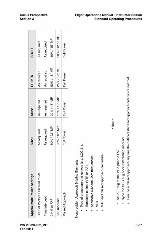
Cirrus Perspective Flight Operations Manual - Instructor EditionSection 3 Standard Operating Procedures
P/N 23020-002_INT 3-87
Non
prec
isio
n A
ppro
ach
Brie
fing
Ele
men
ts
•Ty
pe o
f pro
cedu
re a
nd r
unw
ay (
e.g.
LO
C 3
1),
•Tr
ansi
tion
to fi
nal (
VT
F o
r IA
F),
•A
pplic
able
Nav
and
Com
freq
uenc
ies,
•M
DA
,
•M
AP
and
mis
sed
appr
oach
pro
cedu
re.
• N
ote
•
•S
et A
LT b
ug to
the
MD
A p
rior
to F
AF,
•S
ync
the
HD
G b
ug o
nce
esta
blis
hed
inbo
und,
•E
xecu
te a
mis
sed
appr
oach
any
time
the
outli
ned
stab
ilize
d ap
proa
ch c
riter
ia a
re n
ot m
et.
Ap
pro
xim
ate
Pow
er S
etti
ng
sS
R20
SR
22S
R22
TN
SR
22T
Sta
rt o
f Vec
tors
/ C
lear
ed to
IAF
As
requ
ired
As
requ
ired
As
requ
ired
As
requ
ired
Fin
al In
terc
ept
As
requ
ired
As
requ
ired
As
requ
ired
As
requ
ired
2 N
M to
FA
F50
% /
22"
MP
30%
/ 15
" M
P50
% /
15"
MP
40%
/ 15
" M
P
FAF
Inbo
und
25%
/ 12
" M
P15
% /
12"
MP
25%
/ 12
" M
P30
% /
12.5
" M
P
Mis
sed
App
roac
hF
ull P
ower
Ful
l Pow
erF
ull P
ower
Ful
l Pow
er
Feb 2011

3-88 P/N 23020-002_INT
Flight Operations Manual - Instructor Edition Cirrus PerspectiveStandard Operating Procedures Section 3
Figure 3-4Nonprecision Approach Profile
FAF
MA
P
2 N
M to
FA
FS
low
to 1
00 K
IAS
Set
Fla
ps 5
0%
Fin
al D
esce
nt
/ MA
PA
P D
isco
nnec
t or
Mis
sed
App
roac
h
Mis
sed
Ap
pro
ach
Ful
l Pow
er /
Go
Aro
und
(GF
C 7
00)
Pitc
h 7.
0° -
10°
-
Inte
rcep
t Vy
Fla
ps R
etra
ct
- C
lear
Ter
rain
-
Pos
itive
Rat
e of
Clim
b
- A
irspe
ed A
bove
:
-
80
KIA
S (
SR
22)
- 8
5 K
IAS
(S
R20
)
MD
A10
0kts
Fla
ps 5
0%
FAF
Inbo
und
100k
tsT
ime
Not
ed
Sta
rt o
f V
ecto
rs /
Cle
ared
to
IAF
120k
tsC
ompl
ete
Des
cent
Che
cklis
tB
rief A
ppro
ach
Fin
al In
terc
ept
Com
plet
e B
efor
e La
ndin
g C
heck
list
SR
22_O
P02
_267
1B
Feb 2011

Cirrus Perspective Flight Operations Manual - Instructor EditionSection 3 Standard Operating Procedures
P/N 23020-002_INT 3-89
Go-AroundA go-around should be executed anytime an approach does not meetthe stabilized approach criteria outlined in this manual for instrumentor visual conditions. A go-around should be completed from memorysince it is a time critical maneuver.
In addition to the stabilized approach criteria, execute a go-around/missed approach for these conditions:
• Excessive ballooning during round-out or flare,
• Excessive bouncing or porpoising,
• Landing beyond the first third of the runway,
• Any condition when a safe landing is in question.
The first priority of executing a go-around is to stop the aircraft’sdescent. Smoothly and promptly apply full power while simultaneouslyleveling the wings and pitching the aircraft to stop the descent.Maintain coordination while adding power by applying rudderpressure. Retract the flaps to 50%. Do not fully retract the flaps at thispoint in the go-around because it may lead to excessive altitude loss.
Begin pitching for a climb attitude once the aircraft's descent rate hasbeen stopped and the aircraft is accelerating. Pitch for VX if obstacleclearance is an issue. Pitch for VY for all other situations. Retract flapsto 0% once the aircraft is climbing, clear of obstacles, and above 80KIAS (SR22) or 85 KIAS (SR20).
Procedure (Memory)
1. Autopilot .....................................................................DISENGAGE
GFC 700 - Disengage the autopilot by pressing the go-aroundbutton located on the throttle. The yaw damper will remainengaged after pressing the go-around button.
• Note •
Press the go-around button on the throttle handle whenexecuting a missed approach from an IAP for aircraftequipped with the GFC 700 autopilot.
S-Tec 55X/SR - Disengaged the Autopilot by pressing the APDISC on the control yoke.
2. Power Lever ........................................................FULL FORWARD
Feb 2011

3-90 P/N 23020-002_INT
Flight Operations Manual - Instructor Edition Cirrus PerspectiveStandard Operating Procedures Section 3
Increase power lever to the full forward position. Ensure full poweris used and do not stop at any detents along power lever travel.
3. Flaps ........................................................................................50%
Select flaps to 50% to decrease drag and maintain maximum liftas a climb is initiated.
4. Airspeed.....................................................................SEE BELOW
SR20 - 81 to 83 KIAS
SR22 - 75 to 80 KIAS
5. Flaps ..........................................................................................UP
Verify flaps have been retracted to 0%. If not, ensure the followingcriteria is met before retracting the flaps:
• SR20 - 85 KIAS
• SR22 - 80 KIAS
• Positive rate of climb
• Clear of terrain and obstacles
• FIKI - Retract as soon as practical once conditions are met.Extending flaps in icing conditions can reduce the effectivenessof the elevator and horizontal stabilizer and could potentiallylead to a tail stall.
Instructor Notes
Pilots should never be completely committed to a landing undernormal circumstances. All too often, a pilot continues an unstabilizedapproach and attempts or allows a landing that results in a loss-of-control situation. Pilots must be able to identify safe from unsafesituations, must possess the judgement to abort a bad approach earlyon, and must possess the skills to execute a go-around properly.These skills are basic private pilot skills that might get neglected overtime.
Go-around practice is an important element of Cirrus training coursesfor many reasons. For one, the procedures related to executing a go-around in a Cirrus aircraft may be very different than those used withother types of aircraft. Another reason to practice go-arounds is thatthey are seldom practiced or executed outside the trainingenvironment.
It is recommended to practice go-around procedures at altitude beforeattempting a practice go-around in the traffic pattern. Include this
Feb 2011

Cirrus Perspective Flight Operations Manual - Instructor EditionSection 3 Standard Operating Procedures
P/N 23020-002_INT 3-91
practice during incipient stall practice or when recovering from slowflight. Practice go-arounds at 500 feet AGL, 200 feet AGL and fromround-out altitudes. Closely guard the flight controls, rudder controls,throttle, and flap control when the pilot is practicing or attempting a go-around.
The go-around checklist procedure should be executed by memorywithout hesitation once the decision to go-around is made.
Place significant emphasis on aircraft coordination when practicing ago-around. Pilots should instinctively apply proper rudder inputs whenapplying high power settings at low airspeeds.
Student pilots or pilots transitioning into a new aircraft often put theaircraft into an unstabilized situation that requires a go-around. Duringtraining, take advantage of real-life situations that require a go-around.Ideally, the pilot will initiate the go-around which demonstrates he orshe can recognize an unsafe situation and make a good decision toabort the landing.
Pilots that fail to initiate a go-around may not be able to recognize anunsafe situation or may not possess the judgement to abort. Allowthese pilots to continue the unstabilized approach within your comfortlevel. Ask pointed questions addressing the unstabilized approach.Hopefully, questioning will prompt the pilot into action. Never allow theaircraft to enter an unrecoverable or unsafe situation.
Praise pilots for good decisions when they initiate a go-around.
Completion Standards
• Makes a timely decision to discontinue the approach or landingconsidering approach stability, clearances, and runwayobstructions,
• Applies full power immediately and transitions to a climb pitchattitude for Vy, and maintains Vy +10/-5 KIAS,
• Retracts flaps from 100% to 50% after full power is applied andpitch attitude is established,
• Retracts flaps when climbing, clear of obstacles and airspeedabove 85 or 80 KIAS for an SR20 or SR22/T respectively,
• Assesses potential traffic conflicts and maneuvers as required toavoid traffic conflicts,
Feb 2011

3-92 P/N 23020-002_INT
Flight Operations Manual - Instructor Edition Cirrus PerspectiveStandard Operating Procedures Section 3
• Announces the go-around to the control tower or local trafficafter the aircraft is climbing at the desired airspeed withconfiguration set and when workload permits.
Common Errors
• Fails to recognize and initiate a go-around,
• Fails to apply full takeoff power,
• Fails to maintain coordination during a go-around,
• Neglects to disconnect the autopilot,
• Retracts flaps before adding power,
• Improper pitch control resulting in excessive loss of altitude, stallentry, or both,
• Announces go-around before regaining aircraft control,
• Fails to keep the aircraft aligned and over the runway throughoutthe go-around and initial climb.
Feb 2011

Cirrus Perspective Flight Operations Manual - Instructor EditionSection 3 Standard Operating Procedures
P/N 23020-002_INT 3-93
Approach and Landing Speeds
Approach Speeds SR20 SR22
100% Flaps 78 KIAS 80-85 KIAS
50% Flaps 83 KIAS 85-90 KIAS
0% Flaps 88 KIAS 90-95 KIAS
Short-field (100% Flaps) 78 KIAS 77 KIAS
50 ft Speed - VREF (100% Flaps) 78 KIAS 77 KIAS
Touch-down Speed Slightly Above Stall Speed
Max Demonstrated Crosswind 20 KIAS
Feb 2011

3-94 P/N 23020-002_INT
Flight Operations Manual - Instructor Edition Cirrus PerspectiveStandard Operating Procedures Section 3
Normal LandingNormal landings should be made with 100% flaps. Final approachspeeds should be adjusted to account for gusts exceeding 10 KTS byadding half of the gust factor. Reduce power smoothly and beginslowing from the final approach speed at a time that allows an easytransition from final descent to round-out and flare with minimumfloating or ballooning. Touch-downs should be made on the mainwheels first at speeds slightly above stall. Gently lower the nose wheelafter the mains are on the ground.
Instructor Notes
Normal landing proficiency should be developed before attemptingmore difficult landings, such as short-field, reduced flaps, and power-off landings. Place emphasis on precise airspeed control and touch-down accuracy even during normal landings.
Each landing should be brought to a full stop, allowing sufficient timeto reconfigure and re-trim the aircraft for takeoff. To save time, conducttakeoff and landing practice at runways long enough for a stop and go.Eventually, short-field landing proficiency should be developed andassessed on a shorter runway.
The root causes of landing problems typically result from faultyapproaches, and airspeed and/or power mismanagement. Pilots thatare unable to control the aircraft precisely while in the traffic pattern oron final approach need more time handling the aircraft in slow flight.Emphasize airspeed control and small, accurate control inputs. Ensurepilots are trimming the aircraft for airspeed changes.
Pilots transitioning into the aircraft typically need experience tobecome familiar with the visual sight picture. Demonstrating the firstlanding while highlighting the proper sight picture can be an effectivemethod for teaching proper round-out and flare attitudes. Also,highlight touchdown sight pictures while practicing slow flight.
Maintain defensive positions on rudder pedals, flight controls, andthrottle during all takeoff and landing practice. Be in a position to takeaircraft control immediately if an unsafe situation arises.
Always follow these procedures when landing a Cirrus aircraft:
• Use full flaps,
• Manage airspeed precisely,
Feb 2011

Cirrus Perspective Flight Operations Manual - Instructor EditionSection 3 Standard Operating Procedures
P/N 23020-002_INT 3-95
• Manage power smoothly and precisely. ‘Chopping’ the throttle isnot necessary for normal approaches to landing,
• Normal landing final approach speed for the SR20 and SR22 is78 KIAS and 80 KIAS respectively, plus half the gust factor ifapplicable,
• Touch-down on the main landing gear at approximate stallspeed,
• Trim for all airspeed changes,
• Initiate a go-around after one pilot-induced oscillation orsignificant bounce,
• Always touch-down within the first 1/3 of the runway; initiate ago-around if insufficient runway remains for stopping,
• Hold elevator back pressure after touchdown as airspeeddecays.
Completion Standards
• Considers the wind conditions, landing surface, obstructions,and selects a suitable touch-down point within the first 1/3 of therunway,
• Establishes the aircraft approach and landing configuration andairspeed as recommended, and adjusts pitch and power asrequired,
• Maintains a stabilized approach and recommended airspeed +/-5 KIAS with wind gust factor applied,
• Manages airspeed and power to minimize floating during round-out,
• Touches down smoothly at approximate stalling speed,
• Touches down at or within 400 feet beyond a specified point,with no drift, and with the airplane’s longitudinal axis alignedwith and over the runway centerline,
• Maintains crosswind correction and directional controlthroughout the approach and landing sequence,
• Completes the Before Landing checklist,
• Uses brakes as required while maintaining directional control.Keeps the runway centerline between the main landing gearuntil reaching the desired turnoff point,
Feb 2011

3-96 P/N 23020-002_INT
Flight Operations Manual - Instructor Edition Cirrus PerspectiveStandard Operating Procedures Section 3
Common Errors
• Flares too high creating a stall to hard landing situation,
• Touches down 5 to 10 KIAS above stall speed causing a flatlanding attitude and possible pilot-induced oscillation,
• Fails to keep the aircraft on the centerline throughout the landingroll,
• Fails to initiate a go-around for unsafe landing situations,
• Fails to continuously add back pressure to slow the aircraftduring round-out into the flare,
• Relaxes elevator back pressure during flare to quickly aftertouch-down.
Feb 2011

Cirrus Perspective Flight Operations Manual - Instructor EditionSection 3 Standard Operating Procedures
P/N 23020-002_INT 3-97
Short-Field LandingLandings on short runways should be made with 100% flaps. Finalapproach speeds should be adjusted to account for wind gustsexceeding 10 KIAS by adding half the gust factor. Progressivelyreduce power after clearing all approach obstacles. Proper airspeedand power control should result in an approach with minimal floating inground effect without excessive sink rates during the approach. Touch-down should be made on the main wheels first. Immediately aftertouch-down, ensure power is at idle, lower the nose wheel and applybrakes as required. To decrease stopping distances, considerretracting the flaps and holding the control yoke full aft. Emphasisshould be placed on the accuracy of the touch-down to ensure enoughrunway remains after touch-down to stop the aircraft.
Instructor Notes
Pilots that can consistently demonstrate short-field landings withincompletion standards are typically good ‘stick and rudder’ pilots. Theyconsistently demonstrate the ability to control airspeed effectively andhave a good sense of how to manage the aircraft’s energy whenapproaching to land.
Requiring a pilot to perform landings on runways less than 3000 feet isa good measure of that pilot’s landing ability. However, a short runwaymay not always be readily available. Instructors must be creative whenpracticing short-field techniques on a runway that is not short. Whenpracticing at a longer runway, use existing visible runway features todefine a shorter runway, less than 3000 feet. Taxi-ways, runwaystripes, or adjacent buildings make good landmarks. Ensure pilots areaware of the consequences of landing short or overrunning the‘simulated’ short runway.
Short runways are typically narrower than longer runways. Therefore,it is highly beneficial for pilots to practice and demonstrate short-fieldlanding skills at actual short-fields (2500 - 3000 feet) during private,transition, and recurrent training courses. Cirrus courses requirecross-country legs; use the legs to branch out to airports that havesmaller runways if possible.
Short-field landings should be performed to a full stop and usuallyrequire a back-taxi.
Pilots who lack the skills to perform short-field landings generally haveenergy management issues, stabilized approach issues, or issues with
Feb 2011

3-98 P/N 23020-002_INT
Flight Operations Manual - Instructor Edition Cirrus PerspectiveStandard Operating Procedures Section 3
normal landings. In these cases, go back and hone normal landingskills, with increased emphasis on airspeed control and touch-downaccuracy before continuing with actual short-field practice.
Completion Standards
• Adheres to applicable completion standards for normal landings,
• Touches down at or within 200 feet beyond a specified point,with no side drift, minimum float and with the airplane’slongitudinal axis aligned with and over the runway center,
• Applies brakes and elevator control, as necessary to stop in theshortest distance consistent with safety,
• Executes a go-around if sufficient runway for braking is notavailable.
Common Errors
• Selects and tracks to an aiming point that results in a touch-down beyond the desired landing point,
• Touches down before the specified touch-down point,
• Touches down 200 feet beyond the specified touch-down point,
• Fails to adjust approach angle to compensate for obstacles ifapplicable,
• Fails to recognize the need for a slip to landing for obstacleclearance purposes,
• Fails to adjust airspeed to the recommended short-fieldapproach speed,
• Applies excessive braking causing undue brake wear or loss ofdirectional control.
Feb 2011
Cirrus Perspective Flight Operations Manual - Instructor EditionSection 3 Standard Operating Procedures
P/N 23020-002_INT 3-99
Soft-Field LandingCirrus aircraft are approved for landings on soft field and turf runways.Add 20% to the landing ground-roll distance when landing on a drygrass runway and 60% when landing on a wet grass runway. Alwaysensure that the quality and condition of the runway surface isadequate to support the aircraft. Avoid turf runways with long grass,wet or soggy soil, large ruts or holes. A soft field approach is quitesimilar to a normal landing approach. Touch-downs should be madeon the main wheels first. A soft touch-down will reduce the stress onthe landing gear and make it easier to keep the nose wheel fromdigging into the turf preventing a loss of directional control. Keep thenose wheel off the ground as long as possible by applying sufficientback pressure to the control yoke. A little power can be addedimmediately after touch-down to aid in keeping the nose wheel off theground. Braking should be minimized. Excessive braking could lead toa loss of directional control on the runway. Higher power settings willbe required to taxi on a soft field.
Instructor Notes
Pilots that indicate a need to takeoff and land at actual soft fieldsshould practice soft field takeoff and landings at a real soft field duringtraining. Plan cross-country legs or segments as necessary to add thesoft field takeoff and landing practice.
Pilots with little or no experience with landing on a soft field generallyhave trouble flying a proper glidepath to the touch-down point andassessing height above touchdown. Practice and repetition is requiredto develop the pilot’s skills. It is also recommended to practice the softfield technique on a hard surface until it is mastered, then move to anactual soft field. The instructor should always demonstrate the firstlanding and/or takeoff to make the pilot more comfortable with thedifferences.
Emphasis should be placed on the takeoff and landing performanceimplications when conducting dry or wet grass landings.
Soft-field landings should always be completed to a full stop.
Completion Standards
• Adheres to applicable completion standards for normal andshort-field landings,
Feb 2011
3-100 P/N 23020-002_INT
Flight Operations Manual - Instructor Edition Cirrus PerspectiveStandard Operating Procedures Section 3
• Touches down smoothly on the main landing gear and holds fullelevator aft controls throughout the landing roll and taxi,
• Applies brakes only as required and maintains directionalcontrol without locking the brakes during the landing roll.
Common Errors
• Fails to accurately assess height above touch-down resulting ina flat, hard, or unsafe touch-down,
• Fails to touch-down accurately resulting in a runway over runsituation,
• Fails to hold full elevator back pressure to reduce nose wheelpressure/fatigue,
• Fails to assess runway condition before attempting takeoff orlanding,
• Fails to account for sunrise or sunset times when planning aflight out of, or into an unlit soft field runway.
Feb 2011
Cirrus Perspective Flight Operations Manual - Instructor EditionSection 3 Standard Operating Procedures
P/N 23020-002_INT 3-101
Crosswind LandingCrosswind landings should be made with 100% flaps. It isrecommended to crab the aircraft into the wind sufficiently enough totrack the aircraft along the extended centerline of the runway. Hold thecrab until the beginning of the round-out. At the start of the round-out,enter a slip by applying rudder pressure to align the longitudinal axis ofthe aircraft with the runway and simultaneously apply aileron to keepthe aircraft tracking the runway centerline. Touch-downs should bemade on the upwind main landing gear first, followed by the downwindmain landing gear, and nose gear. Hold aileron correction into the windduring the rollout and apply rudder as necessary to maintaindirectional control.
Instructor Notes
Select airports with runway configurations that have crosswinds duringCirrus courses. Develop normal landing proficiency, when possible,before introducing crosswind techniques. Require pilots todemonstrate crosswind proficiency for all types of landings: normal,short-field, soft field, and power-off as appropriate.
Pilots commonly neglect to develop crosswind personal limitations andend up in situations that require greater skill than they possess.Personal crosswind limitations should be based upon recentexperience. After training, a pilot’s personal crosswind limitationshould be based upon the maximum crosswind to which the pilot hasdemonstrated proficiency. Pilots may increase their personalcrosswind limitations incrementally through training and experience.
Conducting low passes over the runway at approximately 20 feet and75 - 80 KIAS while holding crosswind control inputs is an effective wayto develop crosswind proficiency. Landings may be attempted after thepilot demonstrates the ability to align the longitudinal axis of theaircraft with the runway and track over the runway centerline withoutdrift. Also, practice applying and reducing crosswind inputs at a safemaneuvering altitude at approach to landing speeds until the pilot iscapable of applying inputs smoothly and accurately.
Completion Standards
• Adheres to applicable completion standards for normal, short-field, and soft field landings,
• Identifies need for crosswind technique,
Feb 2011
3-102 P/N 23020-002_INT
Flight Operations Manual - Instructor Edition Cirrus PerspectiveStandard Operating Procedures Section 3
• Smoothly applies rudder and aileron inputs to align thelongitudinal axis of the aircraft with the runway over the runwaycenterline with no drift as the aircraft enters the round-out phaseof landing,
• Holds aileron crosswind control inputs after touch-down andthrough the landing roll,
• Identifies crosswind conditions that exceed the pilot’scapabilities and develops alternative plans for safe landing,
• Selects 100% flaps.
Common Errors
• Applying excessive control inputs resulting in uncoordinatedflight,
• Fails to hold ailerons into the wind after touch-down with no drift,
• Touches down with drift,
• Fails to recognize an unsafe crosswind situation and fails toselect a more suitable landing runway,
• Develops marginal crosswind proficiency on a long and widerunway. Pilot then assumes he or she will be proficient onshorter and narrower runways.
Feb 2011

Cirrus Perspective Flight Operations Manual - Instructor EditionSection 3 Standard Operating Procedures
P/N 23020-002_INT 3-103
Reduced Flap Landings (0% and 50%)While most landings in Cirrus aircraft are performed with 100% flaps, itis important for pilots to develop proficiency landing with 50% or 0%flaps. Landing with less than 100% flaps should be considered a non-typical situation requiring a heightened sense of awareness andcaution. Final approach speeds are increased by 5 KIAS for 50% flapand 10 KIAS for 0% flap landings due to the increased stall speed withreduced flap deflection. A slightly larger traffic pattern will be requiredto descend the aircraft on an approximately 3 degree glidepath to therunway without excessively high descent rates.
Pilots must also be aware that the aircraft will be at a higher angle ofattack as compared to a landing with full flaps on final approach andduring touch-down. Pilots are cautioned to not exceed 10 degrees ofnose high pitch during the round-out and flare to prevent a tail strike.Landing distances with reduced flaps will be greater due to increasedfinal approach and touch-down speeds.
Pilots landing from an instrument approach procedure may elect toland with approach flaps (50%) if changing flap configuration on shortfinal will create an unstabilized approach. Increase final approachspeed and ensure adequate runway remains for safe stopping.
Instructor Notes
Reduced flap landings should be practiced once the pilot hasdemonstrated proficiency performing normal and short-field landings.A zero flap landing can be tied to a flap malfunction scenario; see theflap malfunction section for more information about scenario set up.
Instructors are encouraged to demonstrate a reduced flap landingbefore allowing the pilot to attempt them. Highlight the differences intraffic pattern, speed differences, and correct angle of attack duringthe touchdown while demonstrating the landing to the pilot.
Closely guard the flight controls to prevent the pilot from over-flaringthe aircraft into an excessive nose high attitude during round-out orflare.
To demonstrate an excessive pitch angle, park the aircraft on a levelsurface with the engine shut down, the avionics on, and AHRSaligned. Have two or more people apply pressure to the root of thehorizontal stabilizer to gently lower the tail to the ground. With the pilotseat adjusted to normal flight position, the pilot will be able to see the
Feb 2011
3-104 P/N 23020-002_INT
Flight Operations Manual - Instructor Edition Cirrus PerspectiveStandard Operating Procedures Section 3
outside references of an excessive flare attitude that will induce a tailstrike.
Completion Standards
• Adheres to applicable completion standards for normal, short-field, and/or crosswind landings,
• Selects a runway with adequate distance,
• Adjusts final approach speed as required,
• Adjusts traffic pattern as necessary for a stabilized approach,
• Does not flare the aircraft excessively during round-out andflare.
Common Errors
• Fails to select a runway with adequate distance,
• Overshoots desired touch-down point excessively,
• Over rotates the aircraft during round-out or flare,
• Fails to adjust traffic pattern for reduced flap landing,
• Elects to land with 50% flaps in crosswind conditions whennormal procedure calls for 100%.
Feb 2011
Cirrus Perspective Flight Operations Manual - Instructor EditionSection 3 Standard Operating Procedures
P/N 23020-002_INT 3-105
Icing Landing Procedure1. ICE PROTECT System Switch .................................................. On
It is important to ensure the switch has been set to the intendedposition. This is especially true for night operations.
2. ICE PROTECT Mode Switch .......................... HIGH / As Required
HIGH should be selected initially. If ice accumulation rate is low,select NORM. If ice does not shed, select MAX and perform theAnti-ice System Failure checklist.
3. WIND SHLD Push-Button................................. Press As Required
Use the windshield ice protection when residual fluid that is slungfrom the propeller will not keep the windshield free of ice.
• Caution •
To prevent an obstructed view due to residual anti-ice fluid onwindshield, do not operate windshield ice system within 30seconds of landing.
4. Ice Inspection Lights ................................................... As Required
Ice inspection lights will illuminate the leading edges of the wingsand horizontal stabilizer in order to monitor ice accumulation andconfirm fluid flow at night.
5. Flaps ........................................................................................50%
Approaches and landings in icing conditions or with ice adheringto the aircraft should be made with 50% flaps. Extending flaps to100% in icing conditions can reduce the effectiveness of theelevator and horizontal stabilizer and could potentially lead to a tailstall.
6. Airspeed......................................................... Minimum of 95 KIAS
Residual ice on the protected areas and ice accumulation on theunprotected areas of the airplane can cause an increase in stallspeed even with the anti-ice system operating. Refer to the StallSpeeds with 45 Minute Ice Accumulation chart in the TKS Anti-iceSystem supplement.
7. Airspeed on Short Final .....................................................88 KIAS
Airspeed should be no less than 88 KIAS if icing conditions existor with ice adhering to the airframe due to the possibility of anincreased stall speed.
Feb 2011

3-106 P/N 23020-002_INT
Flight Operations Manual - Instructor Edition Cirrus PerspectiveStandard Operating Procedures Section 3
Instructor Notes
Pilots transitioning into a Cirrus equipped with the FIKI system need todevelop proficiency performing the icing landing procedure.Awareness of when to use the procedure needs to be highlighted inthe training. At first, practice the procedure until the aircraft can belanded safely. This procedure may be combined with the 50% flaplandings required by the transition syllabus.
Later in the training, verbally announce to the pilot that ice is adheringto the airframe. Proficient and cognizant pilots will automatically selectand perform an icing landing procedure. Presenting an airframe icescenario when planning to land at a short runway is also a good way toassess the pilot’s decision making process. Pilots should change theirlanding plans, if necessary, to land at a suitable runway.
Completion Standards
• Adheres to applicable completion standards for normal andshort-field landings,
• Identifies the need, actual or simulated by the instructor, toperform the icing landing procedure,
• Selects a runway with adequate landing distance to perform theicing landing procedure considering landing distances andground roll published in the TKS Anti-Ice Supplement.
Common Errors
• Fails to identify the need for the icing landing procedure,
• Neglects to assess the landing distance performanceimplications of the icing landing procedure,
• Lands with over-rotation causing a tail strike.
Feb 2011

Cirrus Perspective Flight Operations Manual - Instructor EditionSection 3 Standard Operating Procedures
P/N 23020-002_INT 3-107
After Landing Complete the After Landing checklist as a flow after clearing the activerunway. Ensure the pitot heat is turned off. The mixture can be leanedif desired. Set the mixture by leaning for max RPM rise.
Procedure (Flow Pattern)
1. Power Lever ................................................................... 1000 RPM
Reduce power to 1000 RPM during taxi. Changes in engine speedshould be used to accelerate or decelerate the aircraft along withminimal braking as necessary.
2. Fuel Pump ...............................................................................OFF
Select Fuel Pump OFF after clearing runway.
3. Mixture (SR22TN/SR22T)......................................................LEAN
Lean the mixture for maximum RPM rise.
It is acceptable to lean the SR20 and SR22 using the sameprocedure described above for high altitude operations or if sparkplug fouling is suspected.
After Landing Flow
SR22_OP02_2947
Feb 2011

3-108 P/N 23020-002_INT
Flight Operations Manual - Instructor Edition Cirrus PerspectiveStandard Operating Procedures Section 3
4. Flaps ..........................................................................................UP
Select flaps to 0% (UP) after clearing runway.
5. Transponder .......................................................................... STBY
Ensure transponder has automatically cycled to STBY. If not,select STBY manually unless directed by ATC.
6. Lights ..................................................................... AS REQUIRED
Reduce external lighting once clearing the runway to the minimumrequired for safe/legal operation so as to avoid creating a hazardto others.
7. Pitot Heat .................................................................................OFF
Select Pitot Heat OFF.
8. Ice Protection System ..............................................................OFF
Select Ice Protection System OFF if used for landing.
Instructor Notes
Pilots should always clear the active runway and come to a completestop before dividing attention to complete the After Landing checklistitems. It is very common for pilots to continue to taxi withoutcompleting items or to complete items during the landing roll or duringthe taxi. Both of these behaviors are unacceptable and more emphasisshould be placed on proper checklist procedures. Emphasizing thecorrect procedures early in training will help develop better habits.
Completion Standards
• Completes the after landing checklist procedure after clearingthe active runway,
• (FIKI) Turns pitot heat off within 45 seconds after landing.
Common Errors
• Completes checklist items during landing ground roll, beforeclearing the active runway, or during taxi,
• Neglects to complete checklist items and/or reference thechecklist after landing.
Feb 2011

Cirrus Perspective Flight Operations Manual - Instructor EditionSection 3 Standard Operating Procedures
P/N 23020-002_INT 3-109
Arrival and Engine ShutdownComplete the Shutdown checklist as a flow pattern. Verify with thechecklist to ensure all items have been accomplished when completedwith the flow. The avionics switch may be left on during engineshutdown. Notify maintenance personnel immediately and do notmove the propeller if a hot magneto is found during the shutdownprocess.
The aircraft should be parked on a ramp or in a hangar. If the aircraft isparked outside, it should be chocked and tied down if possible.
Procedure (Flow Pattern)
1. Fuel Pump (if used) .................................................................OFF
2. Throttle.................................................................................... IDLE
3. Ignition Switch..................................................................... CYCLE
• Caution •
Note that the engine hesitates as the switch cycles throughthe OFF position. If the engine does not hesitate, one or bothmagnetos are not grounded. Prominently mark the propeller
Arrival/Engine Shutdown Flow
SR22_OP02_2948
Feb 2011
3-110 P/N 23020-002_INT
Flight Operations Manual - Instructor Edition Cirrus PerspectiveStandard Operating Procedures Section 3
as being HOT, and contact maintenance personnelimmediately.
4. Mixture ............................................................................. CUTOFF
Reduce mixture control to the full CUTOFF position and ensureengine stops running. If the engine continues to run with themixture at idle, ensure the boost pump is in the OFF position.
5. All Switches..............................................................................OFF
Turn off all remaining switches including the air conditioning andfan if equipped.
6. Magnetos .................................................................................OFF
Turn off magnetos and remove key.
7. ELT........................................................... TRANSMIT LIGHT OUT
After a hard landing, the ELT may be activated. If this issuspected, press the RESET button located below the circuitbreaker panel near the floor by the pilot's right ankle.
8. Chocks, Tie-downs, Pitot Cover ............................. AS REQUIRED
Set parking brake if required, chock both main wheels, use tiedowns under wings and tail if necessary. Place pitot cover andstatic covers if needed.
Instructor Notes
Pilots often become concerned with post flight responsibilities and/ornon-flight-related concerns after landing. It is important to teach thatthe flight is not over until the aircraft is completely secured. Ensureproper checklist procedures are being followed and good routines aredeveloped for each shutdown and post flight.
A quick post flight walk around is recommended after each flight toensure any abnormalities are identified and resolved before the nextflight. Pay attention to brake temperature stickers, wheel pantcondition, and evidence of leaking brake fluid, fuel, or oil under theaircraft.
Completion Standards
• Completes shutdown checklist as described.
Common Errors
• Fails to reference and follow the shutdown checklist procedure,
Feb 2011

Cirrus Perspective Flight Operations Manual - Instructor EditionSection 3 Standard Operating Procedures
P/N 23020-002_INT 3-111
• Fails to turn the A/C or fan to the off position,
• Fails to turn the magnetos off,
• Fails to replace the CAPS pin during post flight.
Feb 2011

3-112 P/N 23020-002_INT
Flight Operations Manual - Instructor Edition Cirrus PerspectiveStandard Operating Procedures Section 3
Feb 2011

Cirrus Perspective Flight Operations Manual - Instructor EditionSection 4 Abnormal and Emergency Procedures
P/N 23020-002_INT 4-1
Section 4Emergency & Abnormal Procedures
GeneralSections 3 and 3A of the Pilot’s Operating Handbook provide theprocedures for handling emergency and abnormal system and/or flightconditions which, if followed, will maintain an acceptable level ofairworthiness and reduce operational risk. The guidelines described inthese sections are to be used when an emergency or abnormalcondition exists and should be considered and applied as necessary.
This section does not reference all emergency and abnormalprocedures that are described in the Pilot’s Operating Handbook.Reference this section for expanded guidelines on the selectedprocedures and cockpit flow diagrams for emergency procedurememory items.
The procedures described in this section are commonly practicedduring flight training as a means to develop and assess a pilot’ssystem and procedural knowledge and his or her ability to makecorrect decisions regarding the failure or emergency situation.Completion standards are provided for pilots and instructors whenassessing performance. Reference the Common Errors sections toanticipate typical errors made by pilots when practicing theseprocedures.
Instructor ResponsibilitiesPilots must be capable of performing emergency and abnormalprocedures while maintaining aircraft control and to make decisionsthat lead to a safe outcome without excessive risk. Emergency andabnormal procedures training is provided to pilots learning to fly newaircraft, conducting recurrent training, or conducting training for anadditional certificate or rating.
Instructional flights inherently have higher risk than normal, point-to-point flights. Repetitive maneuvering to develop new pilot skills andpracticing emergency and abnormal procedures increases theprobability of an accident or incident. The additional risk duringtraining is mitigated by the instructor with the strategies detailed below.It is the instructor’s responsibility to assess the unique circumstancesof each training event and conduct flight training with a high level of
Feb 2011

4-2 P/N 23020-002_INT
Flight Operations Manual - Instructor Edition Cirrus PerspectiveAbnormal and Emergency Procedures Section 4
safety. An accident caused by pilot error while conducting flight trainingis unacceptable.
• The instructor is pilot-in-command and has the authority todiscontinue the flight or maneuver when necessary,
• Limit emergency and abnormal procedure training to VFRweather in airspace and terrain that provides sufficient room formaneuvering or pilot error,
• Conduct emergency and abnormal procedure training in a flighttraining device or simulator when possible,
• Follow the guidelines in this section concerning maneuverlimitations and scenario setup recommendations,
• Take control of the aircraft any time an immediate safety-of-flightthreat arises,
• Maintain defensive positions on flight controls, rudder pedals,and power lever during critical phases of flight or whenconducting emergency and abnormal procedure training,
• Do not create a real emergency by setting up a simulatedemergency improperly,
• Develop fundamental skills, such as: systems knowledge,checklist flow patterns, memory items, before introducingscenarios that require higher level decision-making abilities.
System MalfunctionsSystem malfunctions presented during training provide an opportunityfor the instructor to assess the pilot’s knowledge of the system andability to manage risks associated with the failure. It is not feasible topractice every failure that is possible in the aircraft, nor is it alwaysnecessary. Focus on key failures, ones that have higher probability orgreater severity, during training. Reference the Cirrus Syllabus Suitefor guidance during transition training.
The objective of practicing failures has two parts. First, to develop thepilot’s knowledge and skill required to deal with the specific systemfailure or emergency situation. Second, in doing the first correctly thepilot will learn how to properly handle other failures or emergencysituations that may arise. The latter can be tested by presenting thepilot with a system failure that was not previously rehearsed on a finalevaluation flight. Look for the following pilot actions when assessingthe pilot’s ability to handle emergency or abnormal situations:
Feb 2011
Cirrus Perspective Flight Operations Manual - Instructor EditionSection 4 Abnormal and Emergency Procedures
P/N 23020-002_INT 4-3
• The pilot maintains aircraft control throughout the entireemergency or abnormal procedure. Autopilot usage, if available,can be a useful tool for single pilots dealing with emergencies.However, this may not be appropriate or available under somecircumstances,
• The pilot identifies and correctly analyzes the emergency orabnormal situation,
• For emergencies, the pilot assertively completes the appropriatechecklist memory items and references the checklist if workloadpermits,
• For abnormal procedures, the pilot selects the correct checklistand completes the items as a do-list,
• The pilot exercises sound aeronautical decision making skillsand determines the best course of action considering all theinformation available.
Guidance on Pulling Circuit BreakersPresenting system failures that mimic “real life” behavior createsrealism and increases training effectiveness. Pulling circuit breakers tosimulate system failures creates a high level of failure fidelity butshould be done cautiously. It is the instructor’s responsibility to ensurethe remainder of the flight can be carried out safely with the ‘popped’breaker.
• Caution •
Under no circumstances should any integrated avionics-related circuit breaker be pulled to simulate an instrumentfailure if visual flight cannot be maintained through landing.
The life cycles of circuit breakers in Cirrus aircraft are as follows:
• 2500 cycles for inductive load (most motors, pumps and fans)
• 5000 cycles for resistive load (most avionics equipment)
It is highly unlikely that these cycle limits will ever be reached, even inaircraft that are used specifically for training. For this reason, thetheory of wearing out a circuit breaker prematurely is not backed bycertification data. If the cycle limit is reached, follow the guidance inthe maintenance manual for replacement.
It is often possible to pull the circuit breaker without the pilot beingaware, which increases the realism of the scenario. Do this by
Feb 2011

4-4 P/N 23020-002_INT
Flight Operations Manual - Instructor Edition Cirrus PerspectiveAbnormal and Emergency Procedures Section 4
increasing the workload of the pilot by assigning various avionics-related tasks. Once the pilot is occupied, tell him or her that somethingpeculiar was noticed and that the circuit breaker panel needs to bechecked. Reach over and pull the breaker while you are ‘investigating’the situation. Or, transition into this failure at the conclusion of anotherfailure that required a circuit breaker to be pulled and reset. Forexample, have the pilot pull the AHRS 1 and 2 circuit breakers andpractice some partial panel BAIF. Once finished with the partial panelBAIF, reach over to restore the “popped” circuit breakers and pull analternator circuit breaker.
Checklist Usage for Abnormal ProceduresCompletion of abnormal procedures should be done using the do-listmethod. The appropriate checklist should be directly referred to andeach item should be completed in the order prescribed.
Instructors should teach pilots to call up the appropriate checklist uponrecognizing the abnormal situation or system failure.
Checklist Usage for Emergency ProceduresEmergency checklists should be completed from memory. TheEmergency Procedures section of the POH identifies checklist itemsfor emergency procedures that must be memorized. Execution ofthese procedures is considered time critical and is done withoutreference to a checklist. The checklist should only be referencedduring an emergency if workload permits. Reference the emergencyprocedure flow patterns when practicing the completion of memoryitems.
Practice emergency checklist procedures in the cockpit while on theground until the procedure can be accomplished in a timely manner.
Pilots are encouraged to practice emergency checklist proceduresoften. This can be accomplished on their own during periods of lowworkload in flight.
Feb 2011
Cirrus Perspective Flight Operations Manual - Instructor EditionSection 4 Abnormal and Emergency Procedures
P/N 23020-002_INT 4-5
CAPS DeploymentThe Cirrus Airframe Parachute System (CAPS) is a unique safetyfeature installed in all Cirrus aircraft. CAPS provides a level ofprotection to the pilot and passengers that is not common to mostgeneral aviation aircraft today. However, for CAPS to work, it must bemanually activated by the pilot or a passenger.
The circumstances and decisions to use CAPS may or may not bereadily apparent. The situations when CAPS should be considered willalways be an emergency or pending emergency. The pilot mustassess the risk of continued flight considering all known factors anddetermine the likelihood of a safe outcome. Whenever the safeoutcome of a flight is in question and there is high risk of severe injuryor death, CAPS should be used.
Pilots may encounter situations that require an immediate activation ofCAPS such as: an engine failure after takeoff, mid-air collision, or aloss of control in flight. CAPS must be activated quickly under thesecircumstances to preserve altitude and control airspeed withinacceptable deployment parameters. Pre-briefing these circumstancesoften will help the pilot to react quickly and activate CAPS in a timelymanner, increasing the probability of CAPS working properly.
Emergency situations in an aircraft are always stressful and pilots mayoverlook all available options for surviving the emergency. Pilots whoregularly conduct CAPS training and think about using CAPS will oftenhave a higher probability of deploying CAPS when necessary.
Performing CAPS training in a Cirrus flight training device or simulatoris highly recommended. Visit www.cirrusaircraft.com to find aninteractive map displaying Cirrus Simulator Centers. It is alsorecommended that frequent flying passengers complete CAPStraining in a Cirrus simulator to develop the ability to properly activateCAPS.
Feb 2011

4-6 P/N 23020-002_INT
Flight Operations Manual - Instructor Edition Cirrus PerspectiveAbnormal and Emergency Procedures Section 4
Procedure
1. Airspeed.......................................................MINIMUM POSSIBLE
The maximum demonstrated deployment speed during testing is133 KIAS. CAPS must be activated quickly when aircraft control islost and airspeed is increasing.
2. Mixture (If time and altitude permit) ................................. CUTOFF
It is desirable to shut the engine off prior to CAPS activation.
3. Activation Handle Cover.................................................. REMOVE
4. Activation Handle (Both Hands) ............. PULL STRAIGHT DOWN
CAPS Deployment
SR22_TS02_3390
Feb 2011

Cirrus Perspective Flight Operations Manual - Instructor EditionSection 4 Abnormal and Emergency Procedures
P/N 23020-002_INT 4-7
Approximately 45 lbs of force is required to active CAPS. Pull thehandle with both hands in a chin-up style pull until the handle isfully extended.
After Deployment:
5. Mixture ............................................................... CHECK, CUTOFF
6. Fuel Selector............................................................................OFF
7. Bat-Alt Master Switches...........................................................OFF
If time permits, declare the emergency and announce CAPSactivation prior to turning off the Bat and Alt switches.
8. Ignition Switch..........................................................................OFF
9. Fuel Pump ...............................................................................OFF
10. ELT.............................................................................................ON
11. Seat Belts and Harnesses .............................................. TIGHTEN
12. Loose Items ..................................................................... SECURE
13. Assume emergency landing body position.
Reference the passenger briefing card for the correct emergencylanding body position. Be mindful of airbag seat belts if installed.
14. After the airplane comes to a complete stop, evacuate quickly andmove upwind.
In high winds the parachute may inflate and drag the aircraft aftertouchdown. Remain upwind of the aircraft.
Instructor Notes
All Cirrus aircraft are equipped with the Cirrus Airframe ParachuteSystem (CAPS). Pilots learning to fly a Cirrus aircraft require specifictraining on the proper use of the CAPS system.
The decision to deploy CAPS is the ultimate risk managementexercise, similar to the decision to activate an ejection seat. Thedecision to deploy CAPS should never be taken lightly, but should beused in all warranted situations. Proper training will increase thelikelihood of a successful and correct CAPS deployment should a real-life emergency arise.
CAPS training should be presented in two phases. First, pilots must beable to correctly and quickly deploy the parachute and prepare theaircraft and occupants for touchdown after deployment. This isaccomplished through briefing and rehearsal to develop muscle
Feb 2011

4-8 P/N 23020-002_INT
Flight Operations Manual - Instructor Edition Cirrus PerspectiveAbnormal and Emergency Procedures Section 4
memory coordination to perform the deployment sequence. Asimulator or flight training device is the most useful tool to developthese skill sets.
When training in the aircraft, have the pilot remove the CAPS placardand touch the handle to simulate deployment.
• Caution •
Under no circumstances during a simulated CAPSdeployment should the CAPS handle be removed from thesleeve.
Second, the pilot should be presented with scenarios that lead to adecision to simulate a CAPS deployment. Such situations should bebriefed on the ground and practiced in a flight scenario. It takes a verywell-crafted scenario to lead a pilot to a CAPS deployment decision inflight. Here are some scenario suggestions when conducting CAPStraining in the aircraft.
• Simulate an engine failure over inhospitable terrain or duringnight operations,
• Simulate an engine failure with the pilot in simulated instrumentconditions. It is often effective to do this over an airport withinglide range. Announce to the pilot that ceilings are reported at1000 feet AGL. This requires the pilot to choose between CAPSor an attempted power-off landing,
• Simulate a severe icing encounter while in simulated IFRconditions. Limit and reduce the maximum available power tosimulate performance degradation. Eventually, limit power sothat level flight cannot be maintained.
Using a simulator or flight training device allows for more CAPSdeployment scenarios in a safe, controlled environment such as:
• Engine failures shortly after takeoff,
• Loss of control or mid-air collision simulations,
• Realistic icing scenarios,
• Other emergencies simulated in IMC.
After the pilot decides to activate CAPS, ensure the pilot goes throughthe appropriate post-deployment procedures and secures the cabin,briefs the passengers, and prepares for touchdown. It isrecommended that the instructor take control of the aircraft while thepilot finishes post CAPS deployment procedures.
Feb 2011

Cirrus Perspective Flight Operations Manual - Instructor EditionSection 4 Abnormal and Emergency Procedures
P/N 23020-002_INT 4-9
Emergency DescentThere are multiple situations that require the use of an emergencydescent. For example, fire, medical emergency, or an O2 malfunctionare just a few. Whatever the reason, the main purpose of performingan emergency descent is to lose altitude as quickly as possible toavoid life-threatening hazards. For some scenarios, landing the aircraftat an airport or suitable off-airport landing site or deploying CAPS maybe an additional objective.
To enter an emergency descent, reduce the power to idle and lowerthe nose approximately 10 - 15 degrees to intercept VNE. Pitch theaircraft to VNO if significant turbulence is expected during the descent.
Banking the aircraft to 45 degrees will help the aircraft accelerate morequickly as well as keep loading positive during the maneuver. It isrecommended to bank the aircraft to 45 degrees until heading 90degrees from the previous heading. From there, adjust heading asnecessary for terrain, traffic, and/or a diversion airport.
Set the mixture control as recommended below and turn the boostpump on. Clear the engine every 1000 feet by increasing MP to 15inches, then reducing back to idle. The combination of high airspeedand low power will cause CHTs to cool. It is good practice to allow theengine to warm before applying high power settings. When possiblerestore power to minimum necessary for level flight until CHTs returnto green.
Inform ATC of the emergency and intended actions and request anyassistance if necessary when workload permits.
Training Limitations
• Complete maneuver in VMC,
• Complete maneuver under VFR unless ATC authorization isobtained,
• Complete maneuver in class E or G airspace unless priorauthorization is obtained from the controlling agency,
• SR22T- maintain at least 15” MP above 18,000 feet.
Procedure - Instructor
1. Clear the area visually and with traffic alert system if available,
2. Initiate simulated Engine Fire in Flight or,
Feb 2011

4-10 P/N 23020-002_INT
Flight Operations Manual - Instructor Edition Cirrus PerspectiveAbnormal and Emergency Procedures Section 4
3. Initiate simulated O2 malfunction at high altitude,
4. Guard mixture and fuel selector controls,
5. Announce a target airspeed of VNO,
6. Guard flight controls to prevent an overspeed.
Procedure
1. Power Lever ............................................................................ IDLE
2. Mixture .................................................................. AS REQUIRED,
• SR20 - full rich,
• SR22 - top of green fuel flow arc,
• SR22TN - full rich,
• SR22T - full rich.
3. Airspeed................................................................................... VNE
Decrease pitch to 10 - 15 degrees to intercept VNE. Maintain VNOif turbulence is expected.
Recovery (Training)
• Continue to land if a stabilized approach can be maintained to asuitable runway, or
• Increase pitch to slow the aircraft, level the descent, and
• Increase power to minimum required for level flight at 100 KIASuntil CHTs are within the green arc.
Instructor Notes
Pilots often require practice and repetition to perform an emergencydescent properly while maintaining positive aircraft control throughoutthe procedure. Have the pilot develop the skills to perform anemergency descent before providing scenarios that require a decisionto perform them.
Pilots flying IFR must notify ATC, when workload permits, of theclearance deviation and to declare an emergency. Have pilotsannounce intentions to the instructor when practicing. IFR pilotsshould practice emergency descents in VMC and simulated IMC.
When practicing an emergency descent due to an engine fire, be sureto guard the mixture control and fuel selector switch to prevent the pilotfrom actually shutting the engine down. An emergency descent should
Feb 2011

Cirrus Perspective Flight Operations Manual - Instructor EditionSection 4 Abnormal and Emergency Procedures
P/N 23020-002_INT 4-11
be initiated shortly after the memory items for an Engine Fire In Flightare completed.
When simulating an engine fire in flight, turn the boost pump to lowboost once the emergency descent is initiated and inform the pilot thatthe boost pump must remain in the off position in a real engine firescenario. Place the mixture setting as described in the EmergencyDescent checklist procedure in the respective AFM. Practice themaneuver at VNO to prevent an over speed situation. Use VNE foractual fires in flight.
Completion Standards
• Promptly recognizes the need for an emergency descent andenters the maneuver,
• Banks aircraft to 45 degrees during the start of the maneuver toload the aircraft and increase descent rate,
• Maintains airspeed +0/-5 KIAS of target airspeed for maneuver,
• Determines the best course of action considering the nature ofthe emergency.
Common Errors
• Fails to reduce pitch sufficiently to accelerate to the desiredairspeed,
• Overspeeds the aircraft beyond VNE,
• Fails to manage airspeed and altitude properly to execute astabilized approach to landing,
• Fails to consider deploying CAPS at an appropriate altitude.
Feb 2011

4-12 P/N 23020-002_INT
Flight Operations Manual - Instructor Edition Cirrus PerspectiveAbnormal and Emergency Procedures Section 4
Engine Malfunctions OverviewProper pre-flight inspections, operating as per AFM recommendations,and routine maintenance all reduce the likelihood of an in-flight enginemalfunction. Although engine malfunctions are a rare occurrence,pilots must be capable of properly identifying and troubleshootingwhile maintaining aircraft control.
Pilots are encouraged to actively scan engine instrumentation duringflight to preemptively fend off or identify up and coming failures. Payclose attention to oil pressure and CHT status and trends.
Most engine malfunctions should be treated as emergencies. Pilotsshould be familiar with emergency procedure memory items and becapable of completing memory items in a timely fashion. Practicecompleting emergency procedure memory items during recurrenttraining and while sitting stationary in the aircraft.
Training Limitations
• Simulated engine failures on takeoff and power-off return toairport during departure / climb maneuvers are not permitted,
• Simulated engine failures are not permitted in actual IMC orwhen VMC cannot be maintained,
• Ensure the aircraft is in a position to make an airport landing orlanding at a suitable off-airport site when conducting thesemaneuvers in case a real emergency is encountered during thesimulated emergency practice.
Feb 2011

Cirrus Perspective Flight Operations Manual - Instructor EditionSection 4 Abnormal and Emergency Procedures
P/N 23020-002_INT 4-13
Engine Failure In FlightFuel starvation is a major cause of engine failures in-flight. Neglectingto switch fuel tanks or attempting flight beyond fuel reserves are majorcontributing factors. Pilots are encouraged to program a scheduledmessage as a reminder to check the fuel balance every 30 minutes.Proper pre-flight planning and ensuring sufficient fuel reservesconsidering current or changing weather conditions for every flight iscritical.
If time and workload permit, complete the Engine Air-start checklist inattempt to regain engine power. Proceed to the Emergency LandingWithout Engine Power checklist if the engine fails to restart.
Procedure (SR20, SR22)
1. At or above 1000 feet AGL and below 18,000 feet MSL, reducethrottle to idle and verbally announce the engine failure,
2. Clear engine every 1000 feet by increasing MP to 15”.
3. Best Glide Speed....................................................ESTABLISHED
Pitch to maintain altitude until the airspeed reaches best glidespeed, then pitch down to maintain best glide speed.
Engine Failure In Flight
SR22_TS02_3387
Feb 2011
4-14 P/N 23020-002_INT
Flight Operations Manual - Instructor Edition Cirrus PerspectiveAbnormal and Emergency Procedures Section 4
4. Mixture ................................................................... AS REQUIRED
Lean or enrichen the mixture in effort to supply the engine with acombustible fuel-air ratio. Use a smooth but prompt sweepingmotion to re-initiate combustion.
5. Fuel Selector ........................................................ SWITCH TANKS
The engine should start shortly after switching fuel tanks if thecause of the engine failure was due to fuel starvation. Be mindfulof maximum fuel imbalances and fuel reserves required tocomplete the flight.
6. Fuel Pump.......................................................................... BOOST
Turning the boost pump on will help suppress vapors that may bein the fuel lines and/or increase fuel pressure to the injectors. Theengine will not run on the electric boost pump alone.
7. Alternate Induction Air............................................................... ON
Press the center button on the alternate static source when pullingthe alternate induction air control knob.
8. Ignition Switch........................................................ CHECK, BOTH
Switch between the left and right magnetos. Leave the ignition onthe magneto that causes the engine to fire for the remainder of theflight.
9. If engine does not start, proceed to Engine Restart or ForcedLanding checklist, as required.
Feb 2011

Cirrus Perspective Flight Operations Manual - Instructor EditionSection 4 Abnormal and Emergency Procedures
P/N 23020-002_INT 4-15
Procedure (SR22T and TN)
1. At or above 1000 feet AGL, reduce throttle to idle and verballyannounce the engine failure,
2. Clear engine every 1000 feet by increasing MP to 15”.
3. Best Glide Speed.........................................................ESTABLISH
Pitch to maintain altitude until the airspeed reaches best glidespeed, then pitch down to maintain best glide speed.
4. Fuel Selector........................................................ SWITCH TANKS
The engine should start shortly after switching fuel tanks if thecause of the engine failure was due to fuel starvation.
5. Ignition Switch.........................................................CHECK, BOTH
Switch between the left and right magnetos. Leave the ignition onthe magneto that causes the engine to fire for the remainder of theflight.
6. Fuel Pump ......................................................................... BOOST
Turning the boost pump on will help suppress vapors that may bein the fuel lines and/or increase fuel pressure to the injectors. Theengine will not run solely on the electric boost pump if themechanical pump fails. High boost may be required above FL180for vapor suppression.
7. Power Lever ....................................................................1/2 OPEN
Set the power level to half open before adjusting the mixturecontrol. If the engine fires, make future power changes cautiously.Return the throttle to a running position if the engine fails duringfuture throttle movements.
8. Mixture ......IDLE CUTOFF, then slowly advance until engine starts
9. CHTs and Oil Temperature ... VERIFY within GREEN range, warm engine at partial power if required
Recovery (Training)
• If the pilot simulates a CAPS deployment, take aircraft controlwhile the pilot conducts post deployment activities or,
• Initiate a go-around procedure at 500 feet AGL, or higher ifrequired by regulation or safety, when a stabilized approach tolanding at an airport cannot be conducted or,
Feb 2011

4-16 P/N 23020-002_INT
Flight Operations Manual - Instructor Edition Cirrus PerspectiveAbnormal and Emergency Procedures Section 4
• Continue forced landing at an airport.
Instructor Notes
Engine failures can be simulated by reducing the throttle to idle. It isrecommended to clear the engine every 1000 feet by increasing MP to15 inches, then reducing it back to idle.
Do not reduce manifold pressure below 15 inches in a turbo aircraftabove 18,000 feet MSL.
Engine failures are commonly practiced in the airport traffic pattern.While this is a good maneuver to develop a pilot’s ability to complete a180 degree gliding approach to a runway, emphasis ontroubleshooting, positioning the aircraft for a stabilized approach, andlanding accuracy is often overlooked. For the reasons stated above, itis important for pilots to practice power-off approaches to landingsfrom altitudes above normal traffic pattern or from an en route altitude.Emphasis should be placed on proper troubleshooting as described inthe AFM and CAPS procedures. Deploying CAPS should beconsidered as a possible strategy for dealing with any real life enginemalfunctions.
Completion Standards
• Maintains aircraft control with airspeed +/-10 KIAS of VG,
• Quickly steers the aircraft to suitable landing or CAPSdeployment area,
• Positions the aircraft to a point where a stabilized approach tolanding can be made,
• When workload permits, troubleshoots engine failure asdescribed in the AFM,
• Secures engine if engine restart is not possible before landing,
• Simulates an emergency radio call and requests ATC assistanceas necessary,
• Simulates a CAPS deployment at an appropriate altitude andairspeed, if necessary.
Common Errors
• Loses excessive altitude by not pitching to VG soon after theengine failure,
• Fails to troubleshoot failed engine as described in the AFM,
Feb 2011

Cirrus Perspective Flight Operations Manual - Instructor EditionSection 4 Abnormal and Emergency Procedures
P/N 23020-002_INT 4-17
• Does not quickly determine, and steer the aircraft towards asuitable landing or CAPS deployment area and/or decide todeploy CAPS, if warranted, with adequate altitude,
• Overshoots or undershoots intended touchdown point,
• Fails to manage glide angle with flaps and/or side slip asnecessary,
• Fails to simulate declaring an emergency and getting priorityhandling and assistance from ATC,
• Fails to consider surface winds when selecting landing direction.
Feb 2011
4-18 P/N 23020-002_INT
Flight Operations Manual - Instructor Edition Cirrus PerspectiveAbnormal and Emergency Procedures Section 4
Emergency Landing Without Engine PowerThe purposes of completing the Emergency Landing Without EnginePower checklist items are to secure the engine in an effort to reducefire potential after touchdown and to alert ATC of the emergencysituation through communication, transponder code, and ELT.
Turn the aircraft and glide towards an airport if available. Otherwise,glide the aircraft to the best location for CAPS deployment consideringwater, terrain, population density, etc. The flight path indicator onPerspective can be a useful tool to determine if the aircraft is capableof gliding to the intended airport. Monitor the flight path indicator whenthe aircraft is established and stabilized at best glide speed. If the flightpath indicator points beyond the airport depicted on synthetic vision, aglide to the airport may be likely. Consider possible wind changes andthe amount of maneuvering required to line up for a runway as theaircraft descends through altitude.
When reaching 2000 feet AGL, the pilot must make the decisionwhether to continue a gliding approach to landing or to activate CAPS.In many cases, CAPS will be the best option for survival, but it must beactivated in time with sufficient altitude remaining. Do not continue anattempted landing unless landing is assured.
Maintain best glide speed with flaps at 0% until landing is assured.Use flaps to increase the descent angle when landing is assured.Eventually, flaps should be placed to 100% for touch-down. All power-off landings should be made with 100% flaps to reduce touchdownspeed and potential impact forces.
Feb 2011

Cirrus Perspective Flight Operations Manual - Instructor EditionSection 4 Abnormal and Emergency Procedures
P/N 23020-002_INT 4-19
Procedure
1. Best Glide Speed........................................................ ESTABLISH
Pitch trim should be set approximately full aft for best glideairspeed. Pilots may consider using the IAS mode of the autopilotset to best glide to help with workload during the descent.
2. Radio ............................................ Transmit (121.5 MHz) MAYDAYgiving location and intentions
Use the current frequency to transmit the mayday call if currentlyin communication with ATC. Otherwise, transmit on 121.5.
3. Transponder ........................................................... SQUAWK 7700
4. If off airport, ELT ........................................................... ACTIVATE
5. Power Lever ............................................................................ IDLE
6. Mixture ..............................................................................CUTOFF
7. Fuel Selector............................................................................OFF
8. Ignition Switch..........................................................................OFF
9. Fuel Pump ...............................................................................OFF
10. Flaps (when landing is assured) ............................................100%
Emergency Landing Without Engine Power
SR22_TS02_3388
Feb 2011

4-20 P/N 23020-002_INT
Flight Operations Manual - Instructor Edition Cirrus PerspectiveAbnormal and Emergency Procedures Section 4
11. Master Switches.......................................................................OFF
12. Seat Belt(s) ................................................................... SECURED
Recovery (Training)
• Take aircraft control if the pilot simulates a CAPS deploymentwhile the pilot conducts post deployment activities or,
• Initiate a go-around procedure at 500 feet AGL, or higher ifrequired by regulation or safety, when a stabilized approach tolanding at an airport cannot be conducted or,
• Continue forced landing at an airport.
Instructor Notes
The Emergency Landing Without Engine Power checklist is frequentlyoverlooked by pilots conducting engine failure training. Instructors areencouraged to conduct engine failure training outside of the trafficpattern at altitudes that allow the pilot enough time to go through allchecklist procedures. Doing so will also require pilots to determine if agliding approach to landing or CAPS activation is best, given theunique circumstances.
Completion Standards
• Completes the Emergency Landing Without Engine Powerchecklist when workload permits,
• Makes a good decision whether to continue to a landing or toactivate CAPS,
• Maintains best glide speed +/-10KTS.
Common Errors
• Fails to activate CAPS at a sufficient altitude,
• Hesitates to determine, and steer the aircraft towards, an airportwithin glide range,
• Descends at an airspeed much higher than best glide, reducingglide range,
• Fails to set 100% flaps for landing or extends flaps prematurely.
Feb 2011
Cirrus Perspective Flight Operations Manual - Instructor EditionSection 4 Abnormal and Emergency Procedures
P/N 23020-002_INT 4-21
Unexplained Loss of Manifold PressureIf SR22T or SR22TN aircraft experience an unexpected loss of normalmanifold pressure, the engine will typically revert to operation similarto a normally aspirated aircraft at approximately the same altitude.However, continued flight should only be conducted to the nearestsuitable landing place in order to investigate the cause of theunexpected loss of normal manifold pressure.
The four most probable causes are:
1. A leak or rupture at an induction system coupling or a loose orfailed induction coupling hose clamp.
a. This condition does not usually present a significant hazard,other than power loss equivalent to a normally-aspiratedengine.
b. While this condition is the most probable, the following threeconditions may present an immediate hazard to continuedsafe flight. Because it is difficult for the pilot to distinguishbetween a simple induction system leak and any of the morehazardous causes, all unexpected losses of manifold pressureshould be assumed hazardous.
2. A significant leak in the exhaust system.
a. An exhaust leak may present a possible fire hazard. Reducingpower and adjusting the mixture as described reduces thepossibility of an engine compartment fire.
3. A loss of oil pressure to the wastegate actuator due to a generalloss of engine oil pressure.
a. Potentially caused by a failed oil line, oil line fitting, or oil pump
b. Failure to maintain normal full manifold pressure at altitudemay be an early indication of an oil leak and impending loss ofoil pressure.
c. Monitor for reduction in oil pressure; if observed continue todiversion airfield, but prepare for forced landing.
4. A failure of an internal component in the turbocharger.
a. If the pilot experiences a sudden loss of manifold pressureand later observes declining oil pressure, it may be due to afailure of an internal turbocharger component. If there is a lossof oil pressure due to a failure of the turbocharger, engine oilmay be vented through the tail pipe overboard.
Feb 2011

4-22 P/N 23020-002_INT
Flight Operations Manual - Instructor Edition Cirrus PerspectiveAbnormal and Emergency Procedures Section 4
b. Monitor for reduction in oil pressure; if observed continue todiversion airfield, but prepare for forced landing.
Training Limitations
• Limit failure to VMC,
• Maintain at least 15” of manifold pressure above FL180.
Procedure - Instructor
1. Reduce the throttle and announce the loss of manifold pressure,
2. Clear the engine every 1000 feet.
Procedure
1. Power ............... ADJUST to minimum required for sustained flight
2. Mixture ........ ADJUST for EGTs between 1300 to 1400 degrees F
The mixture will need to be enrichened as the aircraft descendsthrough altitude to maintain a combustible fuel-air ratio.
3. Descend to MINIMUM SAFE ALTITUDE from which a landing maybe safely accomplished.
Descent at best glide speed to extend glide range if necessary.
4. Divert to nearest suitable airfield.
Consider CAPS if a landing at a suitable airfield is not available.
5. Radio.............................................Advise ATC landing is urgent orTransmit (121.5 MHz) MAYDAY giving location and intentionswhen workload permits.
6. Oil Pressure ................................................................... MONITOR
A loss of engine oil pressure may cause the loss of manifoldpressure. Plan for a forced landing or CAPS activation if oilpressure is steadily decreasing or low.
7. Land as soon as possible.
Continuously monitor for signs of fire. Shut the engine OFFimmediately at the first indications of a fire and initiate anemergency descent to a landing or CAPS activation.
Feb 2011

Cirrus Perspective Flight Operations Manual - Instructor EditionSection 4 Abnormal and Emergency Procedures
P/N 23020-002_INT 4-23
Recovery
• Continue approach to landing at a suitable airfield, or
• Simulate an engine fire and continue scenario.
Instructor Notes
Simulate this failure by closing the throttle to the desired manifoldpressure and announcing the loss of manifold pressure. For full effectof the scenario, it is recommended to conduct this failure at altitudesabove 10,000 feet MSL.
It is recommended to conduct this failure below FL180 while VFR. Donot reduce power below 15” of manifold pressure above FL180. Whilea rupture in the upper deck in the most likely cause of the failure, thereis a potential fire hazard due to a turbo failure.
Ensure pilots are aware of the fire hazard and include the fire potentialin their subsequent decisions. Carefully investigate oil pressure,EGTs, and TITs looking for indications of a failed or blocked turbo. Anindication of a blocked turbo may be if EGTs on the same side of theengine (i.e. 1, 3, 5) are all equally higher or lower than the oppositeside (i.e. 2, 4, 6).
Completion Standards
• Recognizes the failure and promptly completes the emergencychecklist items,
• Selects a suitable diversion airport and completes necessaryarrival tasks,
• Maintains aircraft control, using available power to minimizedescent rate,
• Monitors engine indications and describes possible indicationsof turbo or wastegate failures,
• Continuously monitors for signs of fire.
Common Errors
• Fails to describe the potential causes of the failure,
• Does not treat the failure as a potential emergency,
• Fails to land at the nearest suitable airport,
• Fails to maintain aircraft control due to the increased workload.
Feb 2011

4-24 P/N 23020-002_INT
Flight Operations Manual - Instructor Edition Cirrus PerspectiveAbnormal and Emergency Procedures Section 4
Engine Roughness or Partial Power LossIf a partial engine failure permits level flight, land at a suitable airfieldas soon as conditions permit. If conditions do not permit safe levelflight, use partial power as necessary to set up a forced landingpattern over a suitable landing field. Always be prepared for acomplete engine failure and consider CAPS deployment if a suitablelanding site is not available. Refer to the AFM Section 10, SafetyInformation, for CAPS deployment scenarios and landingconsiderations.
Procedure - Instructor
1. Engine roughness - verbally announce engine roughness, surging,miss-firing, etc,
2. Partial power loss - reduce throttle and announce power loss.
Procedure
1. Air Conditioner (if installed) ......................................................OFF
2. Fuel Pump.......................................................................... BOOST
Selecting BOOST on may clear the problem if vapor in theinjection lines is the problem or if the engine-driven fuel pump haspartially failed. The electric fuel pump will not provide sufficientfuel pressure to supply the engine if the engine-driven fuel pumpcompletely fails.
3. Fuel Selector ........................................................ SWITCH TANKS
Selecting the opposite fuel tank may resolve the problem if fuelstarvation or contamination in one tank was the problem.
4. Mixture ............................. CHECK appropriate for flight conditions
5. Power Lever .......................................................................SWEEP
Sweep the Power Lever through range as required to obtainsmooth operation and required power.
6. Alternate Induction Air............................................................... ON
A gradual loss of manifold pressure and eventual engineroughness may result from the formation of intake ice. Openingthe alternate engine air will provide air for engine operation if thenormal source is blocked or the air filter is iced over.
7. Ignition Switch...................................................... BOTH, L, then R
Feb 2011

Cirrus Perspective Flight Operations Manual - Instructor EditionSection 4 Abnormal and Emergency Procedures
P/N 23020-002_INT 4-25
Cycling the ignition switch momentarily from BOTH to L and thento R may help identify the problem. An obvious power loss insingle ignition operation indicates magneto or spark plug trouble.Lean the mixture to the recommended cruise setting. If enginedoes not smooth out in several minutes, try a richer mixturesetting. Return ignition switch to the BOTH position unlessextreme roughness dictates the use of a single magneto.
8. Land as soon as practical.
Consider the use of CAPS if a safe landing at a suitable airportcan not be guarantied.
Recovery (Training)
• Take aircraft control if the pilot decides to simulate a CAPSdeployment while the pilot conducts post deployment tasks, or
• Verbally announce that roughness or power loss was alleviatedand restore power to normal, or
• Initiate a go-around procedure at 500 feet AGL, or higher ifrequired by regulation or safety, when a stabilized approach tolanding at an airport cannot be conducted, or
• Continue landing.
Instructor Notes
Simulating engine roughness or a partial power loss can be a goodmethod to prompt pilots to consider means of troubleshooting a failingengine.
Initiate this failure shortly after a pilot makes an adjustment to anengine control, such as turning off a boost pump, leaning the mixture,or making a power reduction. It can also be a good way to get pilots torealize the implications of not properly controlling fuel to air ratiosduring climbs or descents.
Simulating engine roughness and announcing erratic fuel flowindications is a good scenario to present to pilots flying turbo aircraft.These scenarios allow the instructor to assess a pilot’s knowledge ofengines, engine controls, and ADM skills.
Completion Standards
• Troubleshoots the engine roughness or partial power lossconsidering engine indications, environmental conditions, andengine control positions,
Feb 2011

4-26 P/N 23020-002_INT
Flight Operations Manual - Instructor Edition Cirrus PerspectiveAbnormal and Emergency Procedures Section 4
• Steers the aircraft towards a suitable landing airport,
• Maintains safe altitude until a glide to landing can be made,
• Continuously plans for an engine failure,
• Simulates declaring an emergency and receives priorityhandling and assistance from ATC if simulated conditionswarrant.
Common Errors
• Prematurely starts a descent with a partial power loss or roughengine before aircraft is within a position to glide to the airport,
• Fails to properly troubleshoot and recognize the reason forengine roughness or power loss,
• Fails to maintain aircraft control while troubleshooting engineroughness or power loss,
• Fails to contact ATC declaring an emergency and requestingpriority handling, if necessary,
• Fails to determine an appropriate landing spot or to initiate aCAPS deployment.
Feb 2011
Cirrus Perspective Flight Operations Manual - Instructor EditionSection 4 Abnormal and Emergency Procedures
P/N 23020-002_INT 4-27
Loss of Oil PressureA loss of oil pressure is an emergency situation that typically results ina catastrophic engine failure. Immediate action by the pilot is requiredto steer the aircraft towards a suitable landing or CAPS deploymentarea. Reduce power to minimum for sustained level flight to extendengine life but preserve altitude as long as possible in preparation foran engine failure.
A rise in oil temperature due to the loss of oil pressure may or may notbe seen. Do not immediately overlook a low oil pressure situation asan indication problem if oil temperature does not rise. Indicationproblems generally are identified by erratic and quick changes inpressure. A true loss of oil pressure is typically identified by a gradualand consistent decrease in pressure. Pilots are encouraged to monitoroil pressure during routine scanning to identify oil pressure issuesearly.
Procedure - Instructor
• Verbally announce the OIL PRESS message is present,
• After the pilot investigates oil temperature and pressure,announce that oil pressure is less than 10 PSI,
• Simulate engine seizure within 3-5 minutes of announcingfailure by closing the throttle to idle,
• Clear engine every 1000 feet after simulated engine failure.
Procedure
1. Oil Pressure Gauge ........................................................... CHECK
High oil temperature may or may not accompany low oil pressure.
If pressure low:
a. Power ...................... REDUCE to minimum for sustained flight
b. Land as soon as possible.
c. Prepare for potential engine failure.
(1) Continually select suitable forced landing fields.
(2) Prepare for CAPS activation if necessary.
Recovery (Training)
• Take aircraft control if the pilot simulates a CAPS deploymentwhile the pilot conducts post deployment activities, or
Feb 2011

4-28 P/N 23020-002_INT
Flight Operations Manual - Instructor Edition Cirrus PerspectiveAbnormal and Emergency Procedures Section 4
• Initiate a go-around procedure at 500 feet AGL, or higher ifrequired by regulation or safety, when a stabilized approach tolanding at an airport cannot be conducted, or
• Continue landing.
Instructor Notes
A loss of oil pressure scenario can be a good lead-in to an enginefailure simulation or possible CAPS deployment simulation. Initiate thisscenario during cruise in an area that is within 15 NM from a non-towered and low-traffic airport if the desired outcome is to conduct aglide approach to a landing.
Completion Standards
• Promptly investigates and determines the reason for the OILPRESS message,
• Maintains altitude until aircraft is in a position to perform apower-off approach to landing,
• Completes the emergency checklist procedure as described inthe AFM and reduces power to the minimum required for levelflight,
• Adheres to applicable performance expectations for the EngineFailure in Flight Procedure if applicable.
Common Errors
• Fails to recognize the cause of the OIL PRESS message,
• Fails to reduce power to minimum for sustained flight for a low oilpressure situation,
• Fails to recognize the severity of a low oil pressure warning,
• Fails to divert to nearest suitable airport,
• Starts descent prematurely, before the aircraft is within gliderange of a suitable runway,
• Fails to consider CAPS as an off-airport landing alternative.
Feb 2011
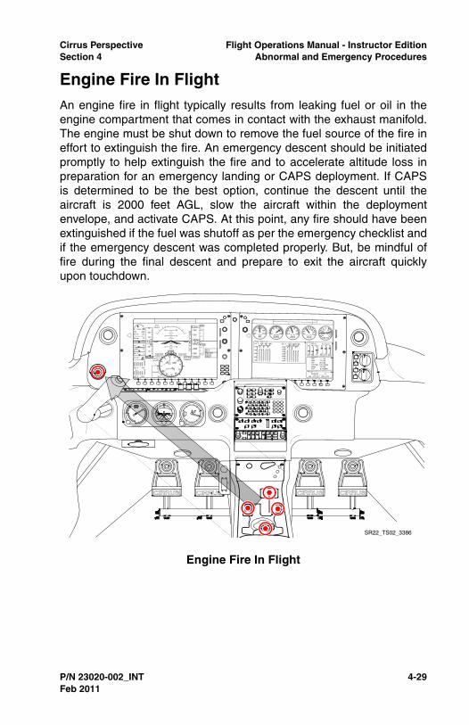
Cirrus Perspective Flight Operations Manual - Instructor EditionSection 4 Abnormal and Emergency Procedures
P/N 23020-002_INT 4-29
Engine Fire In FlightAn engine fire in flight typically results from leaking fuel or oil in theengine compartment that comes in contact with the exhaust manifold.The engine must be shut down to remove the fuel source of the fire ineffort to extinguish the fire. An emergency descent should be initiatedpromptly to help extinguish the fire and to accelerate altitude loss inpreparation for an emergency landing or CAPS deployment. If CAPSis determined to be the best option, continue the descent until theaircraft is 2000 feet AGL, slow the aircraft within the deploymentenvelope, and activate CAPS. At this point, any fire should have beenextinguished if the fuel was shutoff as per the emergency checklist andif the emergency descent was completed properly. But, be mindful offire during the final descent and prepare to exit the aircraft quicklyupon touchdown.
Engine Fire In Flight
SR22_TS02_3386
Feb 2011

4-30 P/N 23020-002_INT
Flight Operations Manual - Instructor Edition Cirrus PerspectiveAbnormal and Emergency Procedures Section 4
Procedure - Instructor
1. Verbally announce fire or smoke from the cowling,
2. Pilot should simulate setting mixture to idle cutoff and fuel selectorto the off position,
• Note •
Prevent the pilot from setting mixture to idle cutoff and fuelselector to the off position.
3. Reduce throttle to idle to simulate engine shutdown,
4. Initiate emergency descent,
5. Clear engine every 1000 feet of altitude loss,
• Note •
Limit power additions to 15” of MP to less than 3 seconds toprevent an increase of airspeed and possible overspeedsituation.
Procedure
1. Mixture ............................................................................. CUTOFF
Placing the mixture to idle cutoff stops fuel flow at the mixturecontrol valve located in the engine-driven fuel pump. This is theclosest fuel cutoff point to the engine.
2. Fuel Pump................................................................................OFF
Turning the auxiliary fuel pump off reduces remaining fuelpressure in the fuel system.
3. Fuel Selector ............................................................................OFF
Selecting the OFF position cuts off the fuel flow behind the enginefirewall.
4. Airflow Selector ........................................................................OFF
Select OFF the reduce the chance of contaminated air fromentering the cabin.
5. Power Lever ........................................................................... IDLE
Reduce the power lever to IDLE to further reduce the chance offire and to use remaining oil pressure to increase propeller pitch.
6. Ignition Switch..........................................................................OFF
Feb 2011

Cirrus Perspective Flight Operations Manual - Instructor EditionSection 4 Abnormal and Emergency Procedures
P/N 23020-002_INT 4-31
Turning the ignition switch to OFF further reduces the likelihood ofcombustion in the cylinders.
7. Cabin Doors .......................................................PARTIALLY OPEN
Partially open the cabin doors to remove smoke and fumes fromthe cabin. Be mindful of door position when activating CAPS.
8. Land as soon as possible.
A high probability exists that an off-airport landing will be required.Use CAPS when a safe landing is in doubt, preferably above 2000feet AGL.
Recovery (Training)
• Simulate a CAPS deployment. See Simulated CAPSDeployments section, or
• Continue emergency descent to a landing, or
• Complete a go-around at or above 500 feet AGL.
Instructor Notes
An engine fire scenario can be a good lead-in to a forced landingscenario, emergency descent, and/or a simulated CAPS deployment.It is recommended to initiate the failure during cruise flight, at least3000 feet AGL, by verbally announcing smoke from the cowling. Seethe Emergency Descent or Simulated CAPS deployment sections asnecessary. Engine restarts should not be attempted.
Ensure that the pilot reduces speed and follows the proper CAPSdeployment procedure including choosing a safe deployment altitude.
When conducting an emergency descent over an airport, continue thedescent to landing if a stabilized approach can be maintained throughtouchdown. Or, initiate a go-around by 500 feet AGL or higher if safetyor regulations dictate. Pilots attempting a landing from an emergencydescent often have trouble slowing the aircraft from VNE to best glideand landing speeds. Repetition is usually required to master thismaneuver.
Completion Standards
• Completes the Engine Fire checklist items from memory in atimely manner,
• Establishes an emergency descent smoothly and promptly andmaintains VNO +0/-5 KIAS,
Feb 2011
4-32 P/N 23020-002_INT
Flight Operations Manual - Instructor Edition Cirrus PerspectiveAbnormal and Emergency Procedures Section 4
• Determines best course of action to recover the aircraft,considering CAPS, off-airport landing, or airport landing,
• Completes the Emergency Landing Without Engine Powerchecklist memory items,
• Properly executes a go-around when conditions warrant.
Common Errors
• Fails to complete Engine Fire checklist memory items,
• Does not initiate emergency descent correctly and promptly ifconditions warrant,
• Fails to correctly determine whether to land at an airport, landoff-airport, or deploy CAPS.
Feb 2011

Cirrus Perspective Flight Operations Manual - Instructor EditionSection 4 Abnormal and Emergency Procedures
P/N 23020-002_INT 4-33
Electrical Malfunctions OverviewCirrus aircraft are equipped with a robust, fault tolerant electricalsystem with redundant sources of power and protective devices. It isimportant for pilots to be knowledgeable of the aircraft’s powergeneration, power distribution, indicating systems, and caution andwarning systems because the aircraft’s primary flight instruments relyon electrical power for operation. During flight training, multipleelectrical failures will be simulated to develop and assess the pilot’sknowledge of the electrical system, troubleshooting techniques, anddecision making. Use the guidance in this section, coupled with theprocedures detailed in the Pilot’s Operating Handbook, when handlingtraining of electrical malfunctions.
Instructor Notes
A good method to evaluate a pilot’s knowledge of the electrical systemand aeronautical decision making skills is to introduce electricalmalfunction scenarios during training. Ensure pilots are able todescribe the aircraft’s power generation, basic power distribution, andtroubleshooting methods before presenting electrical malfunctions inflight.
CATS II for Avidyne, and CATS III for Perspective are great resourcesfor learning and teaching the aircraft’s electrical system. Reference thePOH, Section 7 for additional information.
Conducting electrical malfunction scenarios under VFR and simulatedIFR flight creates more training flexibility and allows pilots to carry outdecisions made in flight.
External factors greatly affect how pilots should troubleshoot electricalmalfunctions. Ensure pilots consider the following factors whenbriefing and conducting electrical system malfunctions:
• Day versus night,
• VFR versus IFR,
• Operations in class B or C airspace,
• Various IFR situations including the ability to exit IMC, oroperations in icing conditions.
Training Limitations
• Electrical malfunctions are not permitted in IMC or when VMCcan not be maintained,
Feb 2011

4-34 P/N 23020-002_INT
Flight Operations Manual - Instructor Edition Cirrus PerspectiveAbnormal and Emergency Procedures Section 4
• Limit operations to 10 minutes with alternators turned off,
• Do not turn both batteries off in flight if ATC or intercomcommunication is necessary. Energize batteries before turningalternators back on,
• Do not turn ALT 1, ALT 2, and BATT 1 off if intercomcommunication is needed or if external communication isrequired by the instructor.
• Electrical fire should only be simulated in class E or G airspaceunder VFR or simulated IFR by verbally announcing the fire.
Feb 2011

Cirrus Perspective Flight Operations Manual - Instructor EditionSection 4 Abnormal and Emergency Procedures
P/N 23020-002_INT 4-35
Alternator 1 and 2 FailuresAn alternator failure is recognized through the Crew Alerting System(CAS) on the Primary Flight Display. Pilots are encouraged to call upthe Engine page on the Multi Function Display to verify what hasfailed. Then, reference the appropriate checklist for troubleshooting.
In most cases, an alternator 1 failure is recognized by the following:
• ALT 1 caution,
• Main Bus 1 voltage at approximately 24 volts and Low M Buscaution message,
• Battery 1 discharging and associated caution message.
An alternator 2 failure is recognized by and ALT 2 caution message.No other cautions or warnings are present because alternator 1 iscapable of powering the remaining electrical equipment.
A single alternator failure is typically an abnormal condition, not anemergency procedure. Pilots are encouraged to follow checklistguidance when troubleshooting alternator issues. Reference the CASchecklist group for alternator troubleshooting guidance. The autopilotshould be engaged to decrease pilot workload during troubleshootingefforts.
Distance remaining to destination, weather, and availability ofmaintenance are factors that pilots should consider when determiningthe best course of action with a failed alternator. The Kinds ofOperation Equipment list found in section 2 of the Pilot’s OperatingHandbook allows flight to depart VFR day and night with a failedalternator 2. Alternator 1 is required for all flight dispatches. It isrecommended to land at an airport with maintenance capabilities inthe event of an alternator 1 failure to reduce aircraft down-time.
Procedure - Instructor
1. Pull the ALT 1 or ALT 2 circuit breaker and wait for annunciator, or
2. Turn off the ALT 1 or ALT 2 switch,
3. Allow pilot to identify and respond to the alternator failure,
4. Pull the alternator circuit breaker once pilot restores breakerduring troubleshooting to simulate a second ‘pop’,
5. Allow pilot to determine the best course of action,
6. Restore the failed alternator within 10 minutes.
Feb 2011

4-36 P/N 23020-002_INT
Flight Operations Manual - Instructor Edition Cirrus PerspectiveAbnormal and Emergency Procedures Section 4
Procedure
1. ALT 1 or 2 Circuit Breaker .......................................CHECK & SET
2. ALT 1 or 2 Master Switch ....................................................CYCLE
Do not attempt multiple restarts if the failed alternator does notstart on the initial cycle. If alternator does not reset (low A1Current and M1 voltage):
3. ALT 1 or 2 Master Switch .........................................................OFF
For Alternator 1 Failures:
1. Non-Essential Bus Loads.................................................REDUCE
a. If flight conditions permit, consider shedding the following topreserve Battery 1:
(1) Air conditioning,
(2) Cabin fan,
(3) Landing light,
(4) Yaw servo,
(5) Convenience power (aux items plugged into armrest jack)
2. Continue flight, avoiding IMC or night flight as able (reduced powerredundancy).
Recovery (Training)
• Restore circuit breaker position after pilot decides theappropriate action, within 10 minutes of pulling,
• Allow pilot to carry out decisions made if possible.
Instructor Notes
During training, simulate alternator failures to test a pilot’s systemsknowledge and decision-making ability, and to also to createmeaningful distractions during flight. Ensure the pilot maintains aircraftcontrol, troubleshoots the failed alternator, uses the autopilot tomanage workload while troubleshooting, and considers externalfactors when assessing the impact to flight and subsequent decisions.It is beneficial to discuss and carry out alternator failures with differentexternal factors. After conducting a simulated alternator failure in VFRconditions, conduct a mental exercise of how the situation would havebeen different in IMC. Or, discuss how night conditions might affect
Feb 2011
Cirrus Perspective Flight Operations Manual - Instructor EditionSection 4 Abnormal and Emergency Procedures
P/N 23020-002_INT 4-37
both pilot workload and decisions to continue to the destination ordivert.
The most realistic method of simulating an alternator failure in flight isto pull the ALT 1 or ALT 2 circuit breaker. A diagram of the circuitbreaker panel is useful when finding the desired breaker, especiallywhen pulling from the right seat. It is recommended to practice pullingthe breaker on the ground, without the pilot in the left seat, beforeattempting in flight. Note that the MCU logic module delays the ALTannunciator for approximately three to five seconds. Reference theGuidance on Pulling Circuit Breakers section for more informationabout pulling circuit breakers.
An alternative method to fail an alternator is to reach across and turnoff the alternator switch. This can usually be accomplished without thepilot noticing if he or she is pre-occupied with other realisticdistractions.
As with any abnormal situation, ensure the pilot references theappropriate checklist to aid in troubleshooting the problem. Restorealternator power within 10 minutes of failing the alternator.
Completion Standards
• Promptly recognizes and identifies the failure,
• Uses the autopilot to reduce workload,
• Calls up the appropriate checklist and follows checklistprocedure as a do-list,
• Makes appropriate decisions considering external factors suchas weather conditions, airspace ahead, nature of the failure,ETE to destination, etc.
Common Errors
• Completes checklist items without reference to the checklist,
• Incorrectly identifies the cause of the failure,
• Attempts multiple circuit breaker resets,
• Fails to correctly load-shed.
Feb 2011

4-38 P/N 23020-002_INT
Flight Operations Manual - Instructor Edition Cirrus PerspectiveAbnormal and Emergency Procedures Section 4
Electrical Fire (Cabin Fire In Flight)An electrical fire or cabin fire in flight is an emergency situationrequiring immediate pilot action. The pilot must turn off power sourcesand electrical equipment to eliminate an electrical fire. In VFRconditions, it is recommended to turn off both batteries andalternators. Reference the magnetic compass, backup airspeedindicator, backup altimeter, and outside visual reference for aircraftcontrol.
In IMC conditions, or conditions that require flight by reference toinstruments, turn off all switches except BATT 2 to preserve power tothe primary flight display and backup attitude indicator. There is a highprobability that the source of fire will be eliminated. Turn off BATT 2 ifthe fire continues to burn. Activate CAPS if controlled flight can not bemaintained.
Procedure - Instructor
1. While in VMC or simulated IFR, announce the electrical fire,
Procedure
1. Oxygen System (if applicable) .................................................OFF
Turn off the oxygen system, if applicable, to reduce the chance ofa severe fire in the cabin.
2. Bat-Alt Master Switches........................................ OFF, AS REQ’D
In VFR, turn off all battery and alternator switches. When flight byreference to instruments is required, leave BATT 2 ON.
3. Fire Extinguisher ............................................................ ACTIVATE
• Note •
If airflow is not sufficient to clear smoke or fumes from cabin:
4. Cabin Doors ...................................................... PARTIALLY OPEN
5. Avionics Power Switch .............................................................OFF
6. All other switches .....................................................................OFF
7. Land as soon as possible.
It is not possible to maintain aircraft control in IMC withoutelectrical power to the PFD and/or backup attitude indicator.Activate CAPS if aircraft control can not be maintained.
8. Air Conditioner (if installed) ......................................................OFF
Feb 2011
Cirrus Perspective Flight Operations Manual - Instructor EditionSection 4 Abnormal and Emergency Procedures
P/N 23020-002_INT 4-39
9. Airflow Selector ........................................................................OFF
10. Bat-Alt Master Switches.............................................................ON
11. Avionics Power Switch ...............................................................ON
12. Required Systems ....................................ACTIVATE one at a time
13. Temperature Selector............................................................ COLD
14. Vent Selector......................... FEET/PANEL/DEFROST POSITION
15. Airflow Selector ...............................SET AIRFLOW TO MAXIMUM
16. Panel Eyeball Outlets............................................................OPEN
17. Land as soon as possible.
Recovery (Training)
• Restore electrical power at scenario completion.
Instructor Notes
An electrical fire is an emergency situation. It is recommended topractice this failure in a simulator or flight training device if possible. Asimulated electrical fire while in simulated IMC can be a good setup fora simulated CAPS deployment.
Following the Cabin Fire checklist procedures for VFR and/or IMC willeliminate the intercom feature and will prevent the instructor fromcommunicating with ATC. This procedure may be safely simulated inthe aircraft if the following guidance is followed.
• Adhere to all electrical malfunction limitations at all times,
• Conduct the scenario when ATC communication orcommunication with other aircraft is not necessary for safe flight,
• Discontinue the scenario and restore all power when intercom orexternal communication is necessary for safe flight.
Completion Standards
• Recognizes the severity of the electrical fire and responds bycompleting the Cabin Fire in Flight checklist procedures,
• Takes appropriate action to eliminate cabin smoke and fumes,
• Diverts to nearest suitable airport for approach and landing, or
• Simulates CAPS deployment if aircraft control cannot bemaintained,
• Makes appropriate decisions considering all external factors.
Feb 2011

4-40 P/N 23020-002_INT
Flight Operations Manual - Instructor Edition Cirrus PerspectiveAbnormal and Emergency Procedures Section 4
Common Errors
• Fails to complete Cabin Fire in Flight checklist memory items ina timely fashion,
• Fails to consider VMC or IMC when turning off switches toattempt to eliminate the fire,
• Fails to land the aircraft as soon as possible,
• Fails to recognize if/when aircraft attitude cannot be maintainedin IMC,
• Fails to maintain positive aircraft control due to high workloadsand increased stress.
Feb 2011

Cirrus Perspective Flight Operations Manual - Instructor EditionSection 4 Abnormal and Emergency Procedures
P/N 23020-002_INT 4-41
Wing Fire In Flight
Procedure
• Verbally announce the wing fire,
Recovery (Training)
• Verbally announce the wing fire is extinguished,
• Turn pitot heat, strobe lights, navigation lights, and landing lightsswitches back on as required,
• Carry out scenario to landing if prudent and safe.
Instructor Notes
A simulated wing fire in flight can be a good lead-in to a diversion to analternate airport. Pilots often fail to land as soon as possible, asrecommended by the POH, even after the fire is extinguished. Thisscenario can also be a good lead-in to an emergency descentprocedure.
The Wing Fire In Flight checklist procedure requires pitot heat,navigation lights, strobe lights, and landing/recognition lights to beturned off. Simulate this failure in an area with low congestion. Restorethe lights as required after the pilot turns the lights off.
Completion Standards
• Completes Wing Fire In Flight checklist procedures,
• Slips the wing tip that is on fire away from the wind and cabin orinitiates an emergency descent to extinguish the fire,
• Lands the aircraft as soon as possible.
Common Errors
• Fails to complete the Wing Fire In Flight checklist procedure,
• Fails to slip or enter an emergency descent to extinguish the fire,
• Neglects to land as soon as possible.
Feb 2011

4-42 P/N 23020-002_INT
Flight Operations Manual - Instructor Edition Cirrus PerspectiveAbnormal and Emergency Procedures Section 4
Integrated Avionics Malfunctions OverviewCirrus Perspective avionics are robust, fault tolerant, and redundant.Although a component failure is highly unlikely, it is important to trainpilots how to handle various avionics-related failures. Focus groundand flight training on the following objectives:
• Ability to maintain aircraft control,
• Proper identification of the failed component,
• Knowledge of other avionics equipment affected by the failedequipment, primarily the autopilot,
• Knowledge of information, features, or functions that arerendered inoperative by the failed equipment,
• Proper use of backup instrumentation,
• Knowledge and use of ATC services available to reduceworkload.
The following table is a useful tool that describes how autopilot modesare affected by various Perspective component failures. An ‘X’ in the
Failure ROL HDG NAV APR LVL PITIAS VSALT
GS GP
VNAV
PFD Screen x x x x x x x x x
PFD Powera
a. The autopilot will revert to ROL mode when the PFD power is failed. All lateral modes may be reselected and used.
x x x x x x x x x
ADCb
b. Assumes system with 1 ADC or 2 failed ADCs. All modes of the AP will be avail-able with a single ADC failure in a dual ADC configuration.
x xc
c.Turns to heading or to intercept a course will be made at half standard rate.
x x xd
d. Only the wings level mode will be available with a ADC failure. Use PIT mode or hand fly for vertical control.
x
Single AHRS
x x x x x x x x x
Dual AHRS
GIA 1e
e. The autopilot will revert to ROL and PIT mode upon failure. All other modes may be reselected
x x x x x x x x x
GIA 2 x x x x x x x x x
Feb 2011
Cirrus Perspective Flight Operations Manual - Instructor EditionSection 4 Abnormal and Emergency Procedures
P/N 23020-002_INT 4-43
box means the autopilot mode will be available during the respectiveequipment failure.
Training Limitations
• Limit avionics malfunctions to VMC and when the flight cancontinue in VMC to landing,
• Note •
It is permissible to fly in IMC while in reversionary mode aslong as both the PFD and MFD screens are visible and chartsand checklists are available through other sources.
• Restore power to failed equipment before entering IMC,
• Ensure ATC communication is maintained as required duringfailures,
• Do not power down the Air Data Computer when the altitudereporting (Mode C) capability of the transponder is required byregulations or necessary for safe flight,
• Limit failures to areas of low traffic congestion and instructorworkload.
Instructor Notes
Pulling circuit breakers may be required to realistically conductsimulated avionics failures in the aircraft. The following componentsmay be restored in flight by resetting the respective circuit breaker.
• AHRS 1 and AHRS 2,
• Note •
Maintain straight and level flight during the AHRS alignmentprocess.
• ADC 1 and ADC 2 if applicable,
• PFD,
• MFD,
• GIA 1 and GIA 2,
• Autopilot.
Cirrus recommends conducting these failures in a simulator or flighttraining device that is capable of accurately representing failure modeswhen possible.
Feb 2011
4-44 P/N 23020-002_INT
Flight Operations Manual - Instructor Edition Cirrus PerspectiveAbnormal and Emergency Procedures Section 4
PFD Display Failure and Reversionary ModeIt is possible to enter and exit reversionary mode in flight by pressingthe reversionary mode button.
Although all autopilot modes and all flight and navigation instrumentsare available in reversionary mode, pilots must be aware that certainMFD information, features, and functions are not available inreversionary mode.
The following information and resources will not be available while inreversionary mode:
• Approach charts,
• Checklists,
• Detailed airport and frequency information,
• Most satellite weather products
• Lean assist feature,
• TKS tank selection control,
The following information and resources will not be available with aPFD power loss:
• Baro setting unchangeable with PFD power loss; use backupaltimeter,
• Com volume and squelch adjustment,
• Loss of Com 1 and Nav 1 control; Com 1 defaults to 121.5,
• Note •
The autopilot will revert to roll mode when the PFD is powereddown. It is possible to re-engage any mode of the autopilot.
Procedure - Instructor
• Dim the PFD screen brightness to 0% or,
• Pull both PFD circuit breakers.
Procedure
1. Display Backup .............................................................. ACTIVATE
Press the red button between the MFD and PFD to activate thedisplay backup if the primary instruments are not displayed on theMFD. Use backup charts, checklists, and airport information asrequired.
Feb 2011

Cirrus Perspective Flight Operations Manual - Instructor EditionSection 4 Abnormal and Emergency Procedures
P/N 23020-002_INT 4-45
2. Land as soon as practical.
Recovery (Training)
Upon landing or scenario conclusion,
• Restore PFD screen brightness to AUTO or,
• Restore PFD circuit breakers.
Instructor Notes
A PFD display failure or power loss can be simulated by the followingmethods. Either dim the PFD brightness to 0% or pull both PFD circuitbreakers. Pulling the circuit breakers will force the Perspective avionicsinto reversionary mode. Dimming the screen will require the pilot toforce the avionics into reversionary mode.
VFR and IFR pilots must be comfortable and prepared to operate inreversionary mode. Presenting this scenario in cruise flight withapproximately 10 minutes before the top of descent is effective. Besure to provide ample time for the pilot to become comfortable flying inreversionary mode before entering high-workload phases of flight.
Vertical descent planning, typically accomplished on the Flight Planpage, will only be available through the options on the Direct-Towindow.
Completion Standards
• Recognizes PFD failure and selects reversionary mode,
• Uses the correct modes of the autopilot and/or hand-flies tomaintain aircraft control within applicable private or instrumentpractical test standards,
• Determines the best course of action considering externalfactors, such as weather, ATC services available, airportservices, level of workload, and pilot proficiency,
• Utilizes backup charts and checklists,
Common Errors
• Fails to carry backup charting or checklist resources,
• Fails to recognize the autopilot change to roll mode,
• Inability to control the aircraft while scanning primaryinstruments on the MFD,
• Fails to recognize and account for the loss of Com 1.
Feb 2011

4-46 P/N 23020-002_INT
Flight Operations Manual - Instructor Edition Cirrus PerspectiveAbnormal and Emergency Procedures Section 4
Air Data Computer FailureAn air data failure could be caused by faulty input information. Look forfaulty indications on the standby airspeed and altimeter to verify.Troubleshoot an ADC failure by resetting the ADC circuit breaker(s),switching to the alternate static source, and turning pitot heat on.Adjust the instrument scan to include the backup airspeed andaltimeter.
The following information will not be available during an air data failurewith a single ADC:
• PFD airspeed,
• PFD altitude,
• PFD vertical speed,
• Percent power, except SR22Ts,
• OAT,
• Wind information,
• TAS,
• Transponder Mode C (single ADC).
Pitch control is not available when the LVL autopilot mode is selected.The lateral ROL mode, or wing leveler, is available. Pilots may hand-flyor use PIT mode of the autopilot to maintain vertical control.
Procedure - Instructor
1. Pull the ADC 1 circuit breaker,
2. If dual ADCs are installed, reselect ADC 1 from the PFD sensormenu.
Procedure
1. ADC Circuit Breaker.................................................................SET
If open, reset (close) circuit breaker.
2. Revert to Standby Instruments (Altitude, Airspeed).
Verify the standby instruments are working properly bymaneuvering the aircraft slightly and looking for the expectedchange. i.e. enter a slight climb and verify that airspeed decreasesand altitude increases. Select the alternate static source and verifypitot heat is on.
Feb 2011
Cirrus Perspective Flight Operations Manual - Instructor EditionSection 4 Abnormal and Emergency Procedures
P/N 23020-002_INT 4-47
3. Land as soon as practical.
Recovery (Training)
• Reset the ADC 1 circuit breaker.
Instructor Notes
Simulating an air data failure is a good way to create a partial panelsituation during training for an instrument rating. Failing the air datacomputer will force the pilot to scan and interpret the standby airspeedand altimeter. The failure also limits various modes of the autopilot thatrely on air data information for control. This forces the pilot to hand-flyor use an alternate means to control the aircraft. See the AutopilotFailure Modes table earlier in this section for more information.
During the simulated failure, it is possible to reset the ADC circuitbreaker(s) and restore the ADC in flight.
Completion Standards
• Correctly identifies the ADC failure,
• Completes the Air Data Computer Failure checklist procedure,
• Checks standby airspeed and altimeter indications and selectsalternate static source and pitot heat as necessary,
• Uses the correct modes of the autopilot or hand-flies to maintainaircraft control within applicable private or instrument practicaltest standards.
Common Errors
• Fails to recognize affected modes of the autopilot,
• Fails to control the aircraft airspeed and altitude withinapplicable standards,
• Fails to notify ATC and request assistance as necessary,
• Determines the best course of action considering externalfactors such as: weather, ATC services available, airportservices, level of workload, and pilot proficiency.
Feb 2011

4-48 P/N 23020-002_INT
Flight Operations Manual - Instructor Edition Cirrus PerspectiveAbnormal and Emergency Procedures Section 4
AHRS FailureIn order to lose all AHRS information, aircraft equipped with dualattitude heading and reference systems would need to have a dualAHRS failure. Dual AHRS equipped aircraft will automatically switchfrom one AHRS unit to the other if performance degradation in oneAHRS is recognized by the internal system monitoring. A dual AHRSfailure, or single AHRS failure in aircraft equipped with one AHRS, canbe recognized by the following indications:
• Loss of Synthetic Vision or horizon indications,
• Red “X” over the attitude indicator,
• “ATTITUDE FAIL” annunciator over the attitude indicator,
• Loss of heading information,
• Red “X” over the heading information,
• CDI will remain in the vertical position and provide left and rightof course deviation indications.
It is important to note that the PFD CDI needle will be oriented straightup, and still display accurate course deviations for GPS and LOCcourses. GS information will also be available while conducting ILSapproaches. TRK and DTK can be displayed on the MFD user-defineddata field for reference. Pitch and roll information is obtained throughoutside visual reference or the backup attitude indicator and headinginformation is obtained through the magnetic compass and/or groundtrack.
The GFC 700 autopilot will not be available during a dual AHRSfailure. See the Autopilot Failure Modes table for more information.
Procedure - Instructor
1. Pull both AHRS 1 and 2 circuit breakers, or
2. Pull AHRS 1 circuit breaker. Use PFD softkeys to switch thesensor source back to AHRS 1.
Procedure
1. Verify Avionics System has switched to functioning AHRS
If not, manually switch to functioning AHRS and attempt to bringfailed AHRS back on-line:
2. Failed AHRS Circuit Breaker....................................................SET
Feb 2011

Cirrus Perspective Flight Operations Manual - Instructor EditionSection 4 Abnormal and Emergency Procedures
P/N 23020-002_INT 4-49
If open, reset (close) circuit breaker. If circuit breaker opens again,do not reset.
3. Be prepared to revert to Standby Instruments (attitude / heading).
Left and right course indications will be available on the HSI. Referto the magnetic compass for heading information.
Recovery (Training)
• Reset both AHRS 1 and 2 circuit breakers and maintain straightand level flight through the alignment process.
Instructor Notes
Instrument applicants must demonstrate the ability to conduct a nonprecision approach without the use of primary flight instruments as perthe Instrument Rating Practical Test Standards. Training pilots tohandle a dual AHRS failure by pulling AHRS circuit breakers developsthe skills necessary to pass the instrument rating practical test and willhelp prepare pilots for the unlikely event of a loss of AHRS information.
Pilots typically need ample time conducting BAIF with the AHRS failedbefore attempting more advanced maneuvers, such as non precisionor precision approaches. Increase pilot workload by assigning variousavionics tasks once basic proficiency is demonstrated during partialpanel BAIF. Emphasize small corrections, proper trim, and knownpower settings while conducting partial panel BAIF.
It is possible to reset and re-align AHRS units in flight by resetting thecircuit breaker(s) and maintaining level flight.
Completion Standards
• Recognizes the failed equipment, ensures that the systemswitches the sensor information to AHRS 2 if available,
• Informs the instructor or ATC of failure, assistance needed, andremaining navigation capabilities,
• Determines the best course of action considering externalfactors such as the weather, ATC services available, airportservices, level of workload, and pilot proficiency,
• Maintains aircraft control at all times within applicable practicaltest standards for the procedure or phase of flight beingperformed.
Common Errors
Feb 2011
4-50 P/N 23020-002_INT
Flight Operations Manual - Instructor Edition Cirrus PerspectiveAbnormal and Emergency Procedures Section 4
• Fails to maintain aircraft control within applicable practical teststandards,
• Fails to include backup attitude indicator in instrument scan,
• Fails to include TRK and/or compass heading in scan,
• Over-controls pitch and roll,
• Neglects to inform ATC or the instructor of the failure andrequested assistance,
• Unable to adjust to a partial panel scan,
• Loses aircraft control, requiring instructor intervention, and failsto consider a CAPS deployment.
Feb 2011

Cirrus Perspective Flight Operations Manual - Instructor EditionSection 4 Abnormal and Emergency Procedures
P/N 23020-002_INT 4-51
GIA FailureThe Garmin Integrated Avionics (GIA) 1 powers COM 1, NAV 1, andGPS 1. GIA 2 powers COM 2, NAV 2, and GPS 2. In the event of afailure, the respective COM and NAV will be replaced with a red ‘x’while the COM frequency defaults to 121.5. Before simulating thisfailure by pulling the GIA 1 or 2 circuit breakers, note the frequencybeing used in the respective COM. It is very common for pilots tooverlook the loss of COM or NAV and fail to re-tune the activefrequency in COM 2. Be sure to highlight the change and reset thefrequency as necessary for uninterrupted communication with ATC orother traffic.
Procedure - Instructor
1. Pull GIA 1 or 2 circuit breaker.
Procedure
1. Communication .................................................... USE COM 1 or 2
Use COM 1 if GIA 2 fails or use COM 2 if GIA 1 fails.
2. Navigation ..............................................USE VLOC 2 if applicable
3. Land as soon as practical.
Recovery (Training)
• Reset GIA 1 or 2 circuit breaker.
Instructor Notes
Failing the GIA 1 or 2 can be a good scenario to test a pilot’sknowledge of the avionics components and integration.
Failing GIA 1 causes GPS 1 to power down. The system automaticallyswitches to and uses GPS 2, but navigation is temporarily interrupted.The temporary loss of navigation causes the autopilot to switch fromNAV mode to ROL mode. Pilots often fail to realize the changebecause there will be no sudden turns or changes to flight caused bythe autopilot. Teach pilots to scan the autopilot annunciators frequentlyand especially during system failures. The autopilot is not interruptedwhen GIA 2 is powered down.
It is not recommended to pull GIA 1 and 2 circuit breakerssimultaneously when ATC communication or any form of onboardnavigation is necessary for safe flight.
Feb 2011
4-52 P/N 23020-002_INT
Flight Operations Manual - Instructor Edition Cirrus PerspectiveAbnormal and Emergency Procedures Section 4
Completion Standards
• Recognizes the failed equipment and resets communicationfrequencies as required,
• Re-engages the desired mode of the autopilot if necessary,
• Determines the best course of action considering externalfactors such as weather, ATC services available, airportservices, level of workload, and pilot proficiency.
Common Errors
• Fails to recognize and change COM frequencies as required,
• Fails to recognize the autopilot mode switch from NAV to ROL.
Feb 2011

Cirrus Perspective Flight Operations Manual - Instructor EditionSection 4 Abnormal and Emergency Procedures
P/N 23020-002_INT 4-53
Loss of GPS IntegrityA loss of GPS integrity is an abnormal situation that requires the pilotto reference alternative forms of navigation. Pilots flying IFR shouldnotify ATC immediately of the reduced navigational capabilities. It maybe possible for ATC to provide radar vectors but expect to join victorairways to the intended destination. Also, consider the type ofapproaches available at the destination airport. A GPS approach willnot be possible with a loss of GPS integrity.
Losing GPS integrity may have more impact when flying VFR due tothe lack of ATC services available compared to when flying on an IFRflight plan. The ‘dead reckoning’ mode of the GPS will be helpful formaintaining situational awareness but use this feature with caution.VFR pilots are encouraged to switch navigation sources to VOR andnavigate on victor airways to the final destination.
Procedure
• Verbally announce the loss of integrity, or
• Cover the HSI, ensuring that heading information is available.Remove the cover once the pilot changes the navigation sourcefrom GPS to VOR.
Recovery (Training)
• Verbally announce scenario is over.
Instructor Notes
Pilots flying with advanced cockpits, such as Cirrus Perspective, useGPS for the majority of navigation. GPS is safe, reliable, accurate, andprovides a magnitude of information beyond other navigation sourcesonboard the aircraft. However, it is possible to encounter situationsthat require VOR navigation, such as a loss of GPS integrity orperforming a stand-alone VOR approach.
Simulating a GPS loss of integrity will force the pilot to inform ATC, (onIFR), modify the route of flight, tune VOR frequencies, and set the CDIcourse as desired. These fundamental skills often degrade with timeand periodic practice is required.
Simulating a loss of GPS integrity is a good scenario to perform duringadvanced IFR training, an IPC, private pilot training, and instrumentrating training.
Feb 2011
4-54 P/N 23020-002_INT
Flight Operations Manual - Instructor Edition Cirrus PerspectiveAbnormal and Emergency Procedures Section 4
Completion Standards
• Recognizes failure and selects an alternate form of navigation,
• Advises ATC and requests alternate routing if necessary,
• Determines the best course of action considering externalfactors such as weather, ATC services available, airportservices, level of workload, and pilot proficiency.
Common Errors
• Neglects to notify ATC of failure and request assistance asnecessary,
• Loses situational awareness.
Feb 2011

Cirrus Perspective Flight Operations Manual - Instructor EditionSection 4 Abnormal and Emergency Procedures
P/N 23020-002_INT 4-55
Runaway Autopilot
Procedure
• Apply pressure to the side stick after the autopilot is engaged ormode is changed,
• Hold pressure until the autopilot is disabled or disengaged.
Recovery (Training)
• Discontinue pressure,
• Continue remainder of flight without the autopilot.
Instructor Notes
Simulating an autopilot runaway is helpful to determine if a pilot isactively monitoring flight status and will overpower and disengage theautopilot when necessary.
It is best to simulate this failure shortly after the pilot engages theautopilot or changes autopilot modes. Instructors can cleverly simulatethe runaway by applying pressure to the side stick with their knee.Allow the pilot to overpower the inputs, but reapply pressure once thepilot relaxes control and fails to disconnect the autopilot.
This can be a quick and good scenario to perform when it is desiredthat the pilot hand fly for the remainder of the flight. Doing this at thebeginning of a long IFR flight can be a good scenario to exercise thepilot’s decision making. Or, simply do this at the top of descent to forcethe pilot to hand fly the descent and approach.
• Note •
Do not simulate this failure in flight situations that requireprecise heading or altitude control. Do not put the aircraft intoan attitude with excessive pitch or roll with excessive descentrates.
Completion Standards
• Promptly recognizes failure and overpowers the autopilot tomaintain aircraft control,
• Promptly disconnects or disables the autopilot,
• Determines the best course of action considering externalfactors such as weather, ATC services available, airportservices, level of workload, and pilot proficiency.
Feb 2011
4-56 P/N 23020-002_INT
Flight Operations Manual - Instructor Edition Cirrus PerspectiveAbnormal and Emergency Procedures Section 4
Common Errors
• Fails to overpower the autopilot and maintain aircraft control,
• Fails to disengage or disable the autopilot,
• Fails to hand-fly within applicable practical test standards.
Feb 2011

Cirrus Perspective Flight Operations Manual - Instructor EditionSection 4 Abnormal and Emergency Procedures
P/N 23020-002_INT 4-57
Other Emergency Procedures OverviewThe emergency and abnormal procedures discussed in this sectionare normally the result of the pilot making poor decisions, inadequateplanning, or the pilot lacking fundamental skills. These procedures arepracticed during flight training with the objective of developing decisionmaking skills to avoid these situations.
Instructor Notes
Providing these situations in a scenario format will help develop thepilot’s decision making capabilities as well as his or her abilities tohandle these situations.
The realism of the scenario directly affects the quality of the learningexperience. The instructor must plan these scenarios thoughtfully andanticipate pilot reactions and decisions. Allowing pilots to carry outpoor decisions, while keeping all safety margins intact, provides anexcellent learning experience.
Performing these scenarios in a simulator or flight training device willhelp create realism and increase safety.
See individual procedures for specific limitations.
Unusual AttitudesUnusual attitudes are most likely to be encountered by pilots who lackinstrument skills, VFR pilots who inadvertently entered IMC, or pilotsexperiencing an abnormally high workload. Pilots who have enteredan unusual attitude have temporarily lost aircraft control or failed tomaintain aircraft control. At the moment of recognition, the pilot mustmake an immediate decision if the aircraft can be recovered usingtraditional recovery techniques such as: a manual recovery, engagingthe autopilot (if within limitations), or activating CAPS. Immediateaction by the pilot is required to recover the aircraft regardless of whichrecovery method is chosen.
It is important to note that pilots who have lost aircraft control may bedisoriented beyond the point where traditional, hand flown recoverytechniques are effective. CAPS activation may be the best recoveryoption available.
Preventing unusual attitudes is the best course of action. Pilots whomaintain high levels of IFR proficiency and VFR pilots who remainclear of IMC conditions are less likely to enter an unusual attitude.Frequent recurrent training is helpful, but it is also helpful to frequently
Feb 2011
4-58 P/N 23020-002_INT
Flight Operations Manual - Instructor Edition Cirrus PerspectiveAbnormal and Emergency Procedures Section 4
fly in IFR in order to maintain avionics programming proficiency andfamiliarity with IFR communications and procedures.
Pilots are encourage to use the autopilot during periods of highworkload, but should not become overly-dependent on the autopilot foraircraft control.
Training Limitations
• Minimum recovery altitude is 1500 feet AGL,
• Do not exceed 60 degrees of bank or 30 degrees of pitch up ordown,
• Initiate recovery before VNE is exceeded,
• Conduct maneuver in VMC only,
• Conduct maneuver in class E or G airspace unless permissionfor abrupt maneuvering can be obtained.
Procedure
• Instruct the pilot to close eyes and put head down with viewlimiting device on,
• Take control and put aircraft into unusual attitude, or
• Instruct pilot to continue flying without reference to instrumentsuntil unusual attitude is entered,
• Instruct pilot to look up and take aircraft control,
• Guard flight controls and throttle for correct recovery sequence.
Recovery (Training)
• Nose high: add power while reducing pitch to maintain airspeedand level the wings,
• Nose low: reduce power while leveling the wings and increasepitch after wings are level to stop the descent.
Instructor Notes
Practice unusual attitudes while preparing a pilot for the private pilotand instrument rating practical tests, advanced instrument training,instrument proficiency checks, and normal or partial panel BAIF.
Aircraft equipped with the GFC 700 autopilot have a useful tool to helppilots regain their composure after recovering from an unusualattitude. It must be clear to pilots that the Level (LVL) button should not
Feb 2011
Cirrus Perspective Flight Operations Manual - Instructor EditionSection 4 Abnormal and Emergency Procedures
P/N 23020-002_INT 4-59
be used for upset recovery. Pilots should regain aircraft controlmanually, and are encouraged to engage the LVL mode shortlythereafter. Using the LVL mode for upset recovery may result in anexcessive loss of altitude or recovery may not be possible due to lowaltitude, excessive loads, or if the aircraft’s attitude exceeds thatautopilot engagement limitations. Pilots should activate CAPS anytimeaircraft control cannot be maintained.
Practice nose-high and nose-low unusual attitudes. With the pilot’shead down and view-limiting device on, place the aircraft into anunusual attitude. Make small control inputs that keep roll rates belowthree degrees per second so the pilot is unable to kinestheticallysense what the aircraft is doing.
Watch for signs of motion sickness while conducting unusual attitudes.Discontinue the maneuver and remove the pilot’s view limiting deviceto avoid discomfort.
It is also recommended to practice unusual attitude recoveries whenpracticing partial panel BAIF.
Closely guard the flight controls and throttle during recovery and takecontrol if necessary to keep the aircraft within airspeed limitations.
Completion Standards
• Promptly recognizes the unusual attitude and applies correctiveactions as described above and in the Instrument FlyingHandbook,
• Engages autopilot once the aircraft is recovered,
• Returns the aircraft to the previously assigned heading orcourse, and/or altitude,
• Regains situational awareness.
Common Errors
• Fails to scan and interpret flight attitude quickly,
• Fails to add power from a nose low unusual attitude and losessignificant airspeed and possibly aircraft control,
• Fails to return aircraft to previously assigned heading or course,and/or altitude,
• Fails to initiate recovery or recovers using wrong technique. Forexample, the pilot increases pitch before leveling the wings on anose low recovery placing the aircraft in a steeper spiral.
Feb 2011

4-60 P/N 23020-002_INT
Flight Operations Manual - Instructor Edition Cirrus PerspectiveAbnormal and Emergency Procedures Section 4
TAWS Escape Maneuver
Training Limitations
• Abide by all legal altitude restrictions,
• Do not put the aircraft in a direct and immediate collision coursewith obstacles or terrain other than for normal descent tolanding.
Procedure
• While the pilot is flying, verbally announce TAWS warning.
Recovery (Training)
• Increase pitch and power to avoid a collision with the obstacle orterrain.
Instructor Notes
Creating a safe scenario that leads to a TAWS warning andsubsequent escape maneuver is very difficult and often impossiblewithout a simulator or flight training device. Flying close enough to theground or obstacles to trigger a TAWS warning usually leavesinadequate safety margins and should be approached cautiously whileconsidering all legal altitude requirements.
Consider the following technique when training pilots to respond to aTAWS warning. Adjust the barometric pressure so the depictedaltitude is well below the actual altitude while practicing unusualattitudes. Shortly after the unusual attitude recovery, verballyannounce ‘TERRAIN AHEAD, PULL UP, PULL UP’ to prompt the pilotinto the TAWS escape maneuver.
CFIT accidents can be prevented by pilots maintaining situationalawareness during all phases of flight. Synthetic Vision Technology(SVT) is a great situational awareness tool for avoiding CFIT accidentsbut the pilot must be attentive throughout the entire flight to avoid CFITaccidents. This is especially true when departing or descendingthrough IMC or low-light conditions.
Completion Standards
• Promptly responds to the warning and initiates the TAWSescape maneuver,
• Maintains aircraft control throughout and after maneuver,
Feb 2011

Cirrus Perspective Flight Operations Manual - Instructor EditionSection 4 Abnormal and Emergency Procedures
P/N 23020-002_INT 4-61
• Regains situational awareness,
• Communicates with ATC as necessary.
Common Errors
• Unable to navigate to MFD TAWS page,
• Intentionally ignores TAWS cautions or warnings.
Feb 2011

4-62 P/N 23020-002_INT
Flight Operations Manual - Instructor Edition Cirrus PerspectiveAbnormal and Emergency Procedures Section 4
Inadvertent Flight into IMCInadvertent flight into IMC by VFR and IFR rated pilots is a majorcontributing cause of fatal accidents. Pilots that fail to brief andinterpret weather conditions or intentionally fly below low cloud basesare at the highest risk for unintentional flight into IMC.
Although prevention is the best way to avoid inadvertent flight intoIMC, pilots must be able to maintain aircraft control while safely exitingIMC. The autopilot is a great tool for assisting pilots out of IMC.However, the pilot must be capable of using the proper autopilotmodes to exit the conditions. Returning to the previous VMC is usuallythe best option. However, some situations will require alternativesolutions to exit IMC. This is particularly true while scud running closeto the ground and/or obstacles. Scud running close to the groundincreases the risk for a CFIT or loss of control accident, which aretypically fatal.
Training Limitations
• Abide by all legal altitude restrictions,
• Do not enter IMC unless on an IFR clearance,
• Flight below 500 feet AGL other than for takeoff or landing is notrecommended,
• Do not put the aircraft on a direct collision course with obstaclesor terrain other than normal descent to landing.
Procedure
• Announce the IMC encounter and have the pilot fly with a view-limiting device,
• Describe the weather situation for the intended scenario.
Recovery (Training)
• Remove view limiting device to simulate exiting IMC, or
• Instrument rated pilots obtain IFR clearance to continue.
Instructor Notes
Simulators and flight training devices that have high-quality visualsystems are useful tools for creating inadvertent IMC scenarios. It isalso possible to create realistic and safe scenarios in the aircraft.Obtain an IFR clearance with a block of altitude that allows climb or
Feb 2011
Cirrus Perspective Flight Operations Manual - Instructor EditionSection 4 Abnormal and Emergency Procedures
P/N 23020-002_INT 4-63
descent into the clouds. Have the pilot climb or descend into the IMC,then recover. This can be more effective during night operations.
Another IMC training option is to verbally announce the lower ceilingswhile flying to a destination. Expect the pilot to descend slightly andcontinue on. After a minute, have the pilot place a view limiting deviceon. Again, expect the pilot to descend. Once at a lower altitude allowthe pilot to fly visually. After some time, announce that the pilot has re-entered the clouds. This scenario typically results in the pilot steppingdown to an unsafe altitude. This scenario can be even more effectivewhen the pilot has personal motivation to get to the destination.
Try combining this scenario into a dual purpose, business and training,flight where the pilot is intending to conduct actual business at thedestination. Or, conduct this scenario on the last flight segment of theday when returning to the home airport. At this time, the pilot’s mindwill be focused on getting home and he or she will have a harder timemaking a decision to divert.
Allowing instrument rated pilots to file and receive an IFR clearanceduring this maneuver is a great training exercise.
Completion Standards
• Maintains aircraft control within applicable practical teststandards,
• Uses autopilot correctly to assist in exiting IMC,
• Promptly and correctly changes heading and/or altitude to exitconditions,
• Seeks ATC assistance if necessary,
• Maintains situational awareness.
Common Errors
• Fails to maintain aircraft control by focusing on instrument scan,
• Fails to consider weather patterns when planning the exitstrategy,
• Does not initiate a prompt exit strategy,
• Continues to climb into IMC even at safe altitudes and expectsto escape by turning around.
Feb 2011
4-64 P/N 23020-002_INT
Flight Operations Manual - Instructor Edition Cirrus PerspectiveAbnormal and Emergency Procedures Section 4
Inadvertent Icing EncounterThe severity of an icing encounter is primarily affected by the rate ofaccumulation and the pilot’s ability to quickly escape the icingconditions. Icing situations and scenarios are unlimited. Therefore, it isimportant to brief the factors that affect a pilot’s exit strategy andpractice different scenarios in flight. Icing scenarios can be a usefultool for developing a pilot’s risk management skills. Many icingscenarios are solved by turning around or diverting to an alternateairport. Pilots often have trouble changing their original plans andchoosing a safe alternative.
Pilots flying aircraft certified for flight-into-known-icing (FIKI) may flythrough known icing conditions legally, but must exercise goodjudgement and be continuously aware of conditions to do so safely.Encourage pilots to fly with an instructor for the first time operating inknown icing conditions. Pilots are often surprised by the additionalworkload and decisions that need to be made while intentionally flyingthrough known ice.
Include a takeoff into known icing simulation or real life scenario withALL pilots training in FIKI aircraft.
The ‘No Hazard’ system installed on many Cirrus aircraft is not safe orlegal to fly through known icing conditions. The system may or may notbe a useful tool to prevent or eliminate ice buildup on protectedsurfaces. It is a tool to assist pilots in escaping icing conditions thatwere inadvertently encountered.
Icing scenarios typically apply to instrument rated pilots. However, aninadvertent icing encounter could be combined with an inadvertentIMC encounter when training VFR pilots.
To make icing scenarios more realistic simulate the loss ofperformance by restricting and reducing power. Over time, theinstructor may reduce power enough that level flight cannot bemaintained. This would simulate severe icing conditions or prolongedflight in moderate conditions.
Training Limitations
• Limit icing scenarios to airspace that allows pilot decisions to becarried out through safe completion or recovery,
• Do not intentionally fly a ‘No Hazard’ equipped aircraft intoknown icing conditions,
Feb 2011

Cirrus Perspective Flight Operations Manual - Instructor EditionSection 4 Abnormal and Emergency Procedures
P/N 23020-002_INT 4-65
• Do not fly a FIKI equipped aircraft into conditions that willexceed system performance or intended use.
Procedure
Here are a few suggestions for inadvertent icing encounter scenarios:
Scenario 1- Shortly After Takeoff
Depart on a simulated or actual IFR flight with simulated or actualweather conditions below basic VFR minimums. Shortly after enteringthe clouds on departure announce that the OAT has dropped to nearfreezing. Monitor the pilot to see if he or she includes the wing in his orher routine scan and verifies that the pitot heat on. Shortly after,announce that ice is accumulating on the wing. Pilots will be faced witha tough decision; to return to the airport, or to climb on top of icingconditions. Either option may be correct given a variety ofcircumstances. Announcing a recent pilot report with cloud tops canmake the scenario and pilot’s decision more elusive or straightforward.For pilots flying FIKI equipped aircraft, announce that ice hasaccumulated on protected services before the system was on or thatthe system is not keeping up.
Scenario 2- En Route and/or High Altitude
While in simulated or actual IMC in cruise announce that the OAT hasdropped to near freezing temperatures. Monitor the pilot to see if he orshe includes the wing in his or her routine scan and verify that the pitotheat is on. Ask the pilot what factors he or she considers whendeveloping an exit strategy. Customize a weather scenario that leadshim or her to request a climb or descent. The instructor, playing therole of ATC, should deny the initial request for climb or descent withthe intent of having the pilot assertively inform what is necessary forsafe flight.
Limit and reduce power to simulate degraded performance if the pilotfails to respond to the situation in a timely manner or makes a poordecision to continue in icing conditions.
Scenario 3- Descent to Landing
Simulate an IFR cross-country flight and provide all ATC services andclearances to the pilot. Mimic ATC as closely as possible. During thedescent to the destination airport announce that the aircraft hasentered the clouds and is picking up substantial ice. The reportedweather is at approach minimums. The pilot will be faced with adecision to divert when he or she is close to the intended destination.
Feb 2011

4-66 P/N 23020-002_INT
Flight Operations Manual - Instructor Edition Cirrus PerspectiveAbnormal and Emergency Procedures Section 4
If the pilot decides to continue, provide him or her with an extendedvector to follow traffic, which will increase the icing exposure time.Start limiting and reducing power gradually to simulate the loss ofperformance. Eventually reduce and limit the power until level flightabove 100 KIAS cannot be maintained.
Recovery (Training)
• Verbally announce the icing conditions have been exited andthat scenario is over, or
• Take control of the aircraft once consequences of poor decisionsare understood by the pilot.
Completion Standards
• Scans for ice accumulation in possible icing conditions,
• Turns pitot heat ON in possible icing conditions,
• Switches to alternate induction air,
• Switches to alternate static source,
• Uses available anti-ice and de-ice systems aboard the aircraft toshed or prevent ice accumulation,
• Promptly exits icing conditions considering pertinent weatherinformation and IFR minimum altitudes,
• Does not allow personal motivation or pressure to influence pilotinto a poor decision,
• Maintains aircraft control within applicable instrument practicaltest standards.
Common Errors
• Allows decisions to be influenced by personal motivations andaccepts undue risk,
• Fails to monitor for ice accumulation,
• Fails to seek help or information from ATC,
• Fails to develop and execute an icing exit strategy promptlyresulting in excessive ice accumulation,
• Fails to use the autopilot during periods of high workload andadditional stress.
Feb 2011

Cirrus Perspective Flight Operations Manual - Instructor EditionSection 4 Abnormal and Emergency Procedures
P/N 23020-002_INT 4-67
DiversionA diversion means the pilot has decided the risk of continuing to theintended destination is too great and cannot be mitigated. This isnever an easy decision to make. The situation often starts with aseries of bad decisions that lead to an accident because the pilot’sjudgement was influenced by his or her motivation to get to the originaldestination.
Some reasons to divert include a change in weather, inadequate fuelreserves, equipment malfunctions, passenger discomfort, or pilotfatigue. Whatever the reason, pilots must be capable of recognizing anunsafe situation, implementing risk management strategies, anddeveloping a plan that allows a safe outcome.
The skill of performing a diversion may be difficult for some pilots tomaster, especially if the diversion airport is relatively close by. Pilotsthat are not proficient controlling the avionics will have difficultyperforming the diversion. Review basic avionics skills beforeperforming a high workload diversion.
Once basic skills are demonstrated, create a scenario that tests anddevelops a pilot’s risk management skills. Diversion scenarios do nothave to be elaborate or complex, but must include real life situations.To truly test one’s ability to manage risk effectively, the pilot must bemotivated to complete the flight as intended. This presents thegreatest challenge for the instructor during flight training.
Pilots often make different decisions in real life scenarios versus whatis seen while training because their motivations are different.Integrating training into a pilot’s personal or business purposes canhelp increase a pilot’s motivation and commitment to getting to thedestination.
Another effective scenario is to ask the pilot if he or she mindsdropping a friend off at an airport during training. Even though the pilotmay not know the instructor’s friend, he or she will feel additionalmotivation to get the friend to his or her destination. During the flightintroduce a scenario that requires the pilot to consider a diversion.
Training Limitations
• Adhere to all flight regulations,
• Never jeopardize the safety of flight.
Feb 2011

4-68 P/N 23020-002_INT
Flight Operations Manual - Instructor Edition Cirrus PerspectiveAbnormal and Emergency Procedures Section 4
Procedure
Here are some scenario examples that often lead to diversions. Seethe Inadvertent Icing section for additional guidance.
Scenario 1- Reported High Winds and/or Wind Shear
Select an airport destination that has a single runway or parallelrunways with weather reporting. When the pilot checks destinationweather information announce winds that exceed the pilot’s crosswindlanding capabilities and/or aircraft maximum demonstrated crosswind.If the pilot continues to the destination, announce that a jet or twoexecuted a missed approach due to wind shear encountered on shortfinal.
Take control of the aircraft on short final if the pilot elects to continue toland in the unsafe conditions. Once on the ground, calmly andconsiderately ask the pilot why he or she thought it was safe tocontinue. Discuss possible outcomes and look for future opportunitieswith high crosswinds to help the pilot recognize his or her and aircraft’scapabilities.
Scenario 2- Weather Below Approach Minimums
This scenario is slightly more complex and requires some amount ofsetup. It starts with a longer cross-country flight or a shorter flight thatdeparts with less fuel. Provide the pilot with a weather overviewincluding conditions that require an alternate to be filed. Dictateconditions so that the alternate airport just meets minimum fuelrequirements.
Announce deteriorating weather near or below approach minimumswhile en route when the pilot checks destination weather, or prompt ifnecessary.
Encourage the pilot, if necessary, to review Fuel Over Destination andto calculate fuel remaining at the filed alternate. Announce to the pilotthat only 30 minutes of fuel remain at the alternate and that its weatherhas also been deteriorating.
Allow the pilot to continue or divert. If he or she continues to thedestination, do not let him or her go visual for a landing. While holdingor following the missed instructions, announce that a business jet justlanded on the same approach, but weather was reported unchanged.Simulate weather below approach minimums on this approach as well.This will further reduce fuel reserves.
Feb 2011

Cirrus Perspective Flight Operations Manual - Instructor EditionSection 4 Abnormal and Emergency Procedures
P/N 23020-002_INT 4-69
Hopefully, the pilot will elect to proceed to the alternate and will reducefuel burn to extend range. Also, the pilot should review the actualweather information and approaches available at closer airports tofurther mitigate risk.
Scenario 3- Open Door on Takeoff
Although a simple scenario, leaving a door open for takeoff or openinga door shortly after rotation creates both a distraction and decision forthe pilot during a busy phase of flight. Introduce the scenario as across-country flight that is running late. Pilots must first commit to thedecision to return for a landing and focus attention on maintainingaircraft control simultaneously.
Completion Standards
• Overcomes personal motivation and pressure and makes a safeand prudent decision,
• Maintains aircraft control within applicable completionstandards,
• Uses all information available to make a safe decision,
• Uses the autopilot effectively to reduce workload during periodsof high workload or stress,
• Uses onboard resources to find diversion airport information.
Common Errors
• Fails to recognize the severity of poor decisions,
• Does not recognize an error chain and consequences,
• Fails to reason and/or maintain aircraft control during periods ofhigh workload or increased stress,
• Neglects to use cockpit resources to aid in decision making.
Feb 2011

4-70 P/N 23020-002_INT
Flight Operations Manual - Instructor Edition Cirrus PerspectiveAbnormal and Emergency Procedures Section 4
System Malfunctions Overview
Instructor Notes
Simulating the following system malfunctions will allow the instructor toassess a pilot’s knowledge of that system and how it relates to othersystems in the aircraft. It will also allow the pilot to further develop riskmanagement skills.
It is important that the pilot is able to describe system components,component integration, failure modes, and pilot techniques beforeattempting to practice failures in flight.
Repetition in a non-scenario-based format is recommended for pilotswho need more time on task in order to recognize and handle asystem failure. Once basic skills are mastered it is appropriate tocreate a scenario with the system failure that causes the pilot toexercise risk management skills.
Simulators or flight training devices are excellent tools when trainingpilots to handle system failures. They allow the instructor to createrealistic component failures and allow scenarios to be carried outuninterrupted en route.
Feb 2011

Cirrus Perspective Flight Operations Manual - Instructor EditionSection 4 Abnormal and Emergency Procedures
P/N 23020-002_INT 4-71
Flap MalfunctionA malfunction in the flap system typically results in the flaps failing toextend prior to approach or landing. Pilots must be aware of theadditional landing distance required due to the higher stall andapproach speeds. Pilots are encouraged to select a landing runwaythat is at least 5000 feet long for 0% flap landings. A diversion may benecessary if the runway at the intended destination is not adequate fora safe landing.
Pilots are encouraged to practice reduced flap landings during initialand recurrent training.
Training Limitations
• Reset the circuit breaker before conducting takeoff or landingpractice,
• Minimum runway length is 5000 feet for zero flap takeoff andlanding practice,
• Flaps may be failed in IMC as long as the destination ceiling andvisibility is greater than 1000 feet AGL and 3 SM.
Procedure
• Pull flap circuit breaker en route (preferred), or
• Block flap control when pilot reaches for flap and announce theflaps are inoperative,
• Reset flap circuit breaker before takeoff or landing practice.
Recovery (Training)
• Restore the flap circuit breaker and announce the scenarioconclusion.
Instructor Notes
Failing the flaps in the up position is a good way to test a pilot’s abilityto conduct a zero flap landing. It can also be a risk managementexercise. Plan a flight to an airport with a 3000 - 3500 feet runway andfail the flaps en route by pulling the flaps circuit breaker. Do thiswithout the pilot’s knowledge (see the Guidance on Pulling CircuitBreakers section for more information). The pilot will be faced with adecision to divert to the departure or alternate airport, or accept higherrisk and attempt a landing at the intended destination. Take control of
Feb 2011

4-72 P/N 23020-002_INT
Flight Operations Manual - Instructor Edition Cirrus PerspectiveAbnormal and Emergency Procedures Section 4
the aircraft on short final if the pilot decides to attempt a landing.Proceed to a runway that is 5000 feet or greater and record landingdistances. Pilots will be surprised by the distance required forstopping.
Pulling the flap circuit breaker is a more effective scenario than simplyannouncing the flaps are inoperative. Pilots often fail to realize the flapfailure in the traffic pattern or during an IAP. This scenario will help thepilot detect flap malfunctions in the future.
Completion Standards
• Recognizes the failure after attempting to extend 50% flaps,
• Adjusts speed as necessary to perform a zero flap landing,
• Considers landing distance and selects an appropriate runwayfor a safe landing,
• Adheres to applicable landing completion standards.
Common Errors
• Fails to recognize the flap malfunction and continues landingunknowingly,
• Knowingly attempts a landing on a short runway with inadequatesafety margins,
• Lacks the skills to perform a zero flap landing within applicablecompletion standards.
Feb 2011

Cirrus Perspective Flight Operations Manual - Instructor EditionSection 4 Abnormal and Emergency Procedures
P/N 23020-002_INT 4-73
Oxygen System MalfunctionAll pilots flying an oxygen and/or turbo equipped Cirrus aircraft areencouraged to attend hypoxia training every 5 years. Information aboutfacilities that offer this training can be found on the Cirrus TrainingPortal. Be cognizant of hypoxia signs and symptoms and continuouslymonitor oxygen saturation levels with a pulse oximeter when operatingat altitudes that require the use of supplemental oxygen.
It is critical to ensure adequate oxygen is available for the intendedflight considering altitude and passengers. Careful preflight of allregulators, masks, cannulas, oxygen flow, hoses, and connections isrequired.
An O2 malfunction at high altitude is an emergency situation requiringimmediate and decisive action by the pilot. If supplemental oxygen isnot available at high altitude, an emergency descent must be initiated.Consider using the autopilot in IAS mode set to VNO with the altitudebug set to 10,000 feet MSL, or higher if terrain dictates.
• WARNING •
Intentionally removing supplemental oxygen at or abovealtitudes where supplemental oxygen is required by regulationis reckless and unsafe. The supplemental oxygen system willremain on during all O2 malfunction scenarios. Thesescenarios are intended to teach pilots how to respond tovarious oxygen failures, not to demonstrate hypoxia signs,symptoms, and recovery.
Training Limitations
• Malfunction limited to VFR in airspace and terrain that allows anemergency descent to a minimum of 12,500 feet MSL,
• Oxygen system and masks or cannulas will remain on at allaltitudes that require supplemental oxygen.
Procedure
• Clear area visually and with the traffic alert system beforeinitiating the scenario,
• Announce an oxygen system malfunction, quantity exhaustion,flow blockage, or O2 warning annunciator, or
Feb 2011

4-74 P/N 23020-002_INT
Flight Operations Manual - Instructor Edition Cirrus PerspectiveAbnormal and Emergency Procedures Section 4
• Display physical signs of hypoxia, such as unresponsiveness,loss of consciousness, euphoria, and/or slurred speech.Announce failure once pilot recognizes the issue.
Recovery (Training)
• Continue flight at altitudes that do not require supplementaloxygen, or
• Announce the scenario conclusion and climb back to the desiredaltitude.
Instructor Notes
Pilots learning to fly a turbo-equipped Cirrus should conduct anddemonstrate the ability to handle an O2 Malfunction. Perform thisscenario during a high altitude (greater than 12,500 feet MSL),simulated IFR, cross-country leg. This scenario can lead intoemergency descent training or evaluation. The instructor will provideall IFR clearances, pilots should declare an emergency to theinstructor as they would to ATC.
Perform this procedure in airspace and terrain that allows anemergency descent to at least 12,500 feet MSL or below. Descendingto 10,000 feet MSL is preferred. This may be conducted in VMC orsimulated IMC while VFR. It is recommended to start this malfunctionat an altitude that allows the pilot sufficient time to become stabilizedin an emergency descent.
Completion Standards
• Promptly responds to the malfunction and initiates anemergency descent to a safe altitude,
• Declares an emergency when workload permits andcoordinates with ATC as required,
• Recognizes signs and symptoms of hypoxia in passengers andresponds accordingly.
Common Errors
• Does not understand the severity of an oxygen systemmalfunction at high altitude,
• Fails to perform an emergency descent as described in theemergency descent completion standards.
Feb 2011

Cirrus Perspective Flight Operations Manual - Instructor EditionSection 4 Abnormal and Emergency Procedures
P/N 23020-002_INT 4-75
Power Lever Linkage FailureA stuck throttle results from a linkage failure between the power leverand the throttle plate. The power may be at a high or low powersetting. Individual circumstances dictate the proper reaction by thepilot.
When the power is stuck low and the aircraft is unable to sustain levelflight, the pilot should establish the aircraft at best glide speed andprepare for an emergency landing. CAPS should be considered andactivated above 2,000 feet AGL when the successful outcome of aforced landing is in doubt.
A stuck throttle with a high power setting will require the pilot toperform a power-off landing. The pilot should position the aircraftwithin safe gliding distance from the airport, a runway greater then5,000 feet is recommended, and then shut the engine off with themixture control and establish best glide. The pilot may enrichen themixture to restart the engine if it appears the aircraft will come up shortto the runway.
Pilots who are not confident in their ability to perform this procedureshould consider CAPS as an alternative to the power-off landing.
Training Limitations
• Conduct takeoff scenarios on a runway that is a minimum of 3times the required takeoff ground roll distance,
• For takeoff scenarios, abort the takeoff before the aircraftaccelerates to 35 KIAS,
• For takeoff scenarios, limit the throttle travel to a maximum of30-40% power,
• For landing scenarios, discontinue the scenario and use fullpower to execute a go-around if a stabilized approach to alanding cannot be established by 500 feet AGL,
• Perform this maneuver in VMC only,
• Obtain the necessary clearances and coordinate accordinglywith ATC if necessary,
• Do not shut the engine down with the mixture control.
Feb 2011

4-76 P/N 23020-002_INT
Flight Operations Manual - Instructor Edition Cirrus PerspectiveAbnormal and Emergency Procedures Section 4
Procedure - Instructor
1. Limit throttle travel by blocking movement on takeoff or duringpower reductions,
Procedure
1. Power Lever Movement......................................................VERIFY
Sweep the power lever slowly to determine if any control remains.
2. Power ............................................................................ SET if able
3. Flaps ........................................................................ SET if needed
With a high power setting, consider decreasing airspeed byincreasing the aircraft’s pitch to flap speeds. Set flaps as desiredand continue descent.
4. Mixture ..................................... AS REQUIRED (full rich to cut-off)
To perform a landing with a stuck throttle, the engine will need tobe shut off via the mixture control. It is best to position the aircraftwithin safe gliding distance before turning the engine off.
5. Land as soon as possible.
A stuck throttle should be treated as an emergency situation.Inform ATC of situation and request assistance and priorityhandling as necessary. Be prepared for a power-off landing.
Recovery (Training)
• Announce scenario conclusion and allow free throttlemovement.
Instructor Notes
A simulated stuck throttle scenario often catches pilots by surprise andcan be a good way to assess a pilot’s ability to think and react quicklyin an increased stress environment.
Conduct this failure by limiting throttle travel when the pilot is reducingthe throttle for descent and arrival. Allow the pilot to reduce power toapproximately 65% before blocking and announcing the stuck throttle.
This failure can also be simulated early in the takeoff roll by restrictingthe throttle lever at approximately 30-40%. Do not allow the aircraft toaccelerate past 35 KIAS and promptly take aircraft control if the pilotfails to abort the takeoff.
Feb 2011
Cirrus Perspective Flight Operations Manual - Instructor EditionSection 4 Abnormal and Emergency Procedures
P/N 23020-002_INT 4-77
An actual stuck throttle with a high power setting would require thepilot to shut down the engine with the mixture control when the aircraftis in a position to make a stabilized power-off approach to landing. Themixture control must remain in the proper position for landingthroughout the simulated scenario. Do not shut down engine using themixture control. Simulate shutting the engine down by reducing thethrottle to idle.
Completion Standards
• For takeoff scenario, promptly reduces throttle to idle andapplies brakes as required to stop the aircraft on the runway,
• For landing scenario, simulates notifying ATC of emergency andrequests assistance as necessary,
• For landing scenario, reduces risk by selecting a larger runway,
• For landing scenario, puts the aircraft into a position where astabilized approach to a power-off landing can be accomplished,
• For landing scenario, considers methods of extending glidedistance or performing a go-around if necessary.
Common Errors
• Does not consider engine shutdown and power-off approach forresolving scenario,
• Fails to abort takeoff promptly,
• Fails to execute a power-off approach within applicablecompletion standards.
Feb 2011

4-78 P/N 23020-002_INT
Flight Operations Manual - Instructor Edition Cirrus PerspectiveAbnormal and Emergency Procedures Section 4
Loss of Brake PressurePilots are encouraged to check brakes before taxi and during thedescent checklist during each flight operation as detailed in the normalprocedures checklist. In the event of a loss of brake pressure duringtaxi, the engine should be shutdown before the aircraft comes intocollision hazard with objects on the ground. The aircraft should betowed and repaired prior to flight or self-propelled movement on theground.
If brake pressure is lost during flight, select a wide runway that is atleast 5,000 feet in length. Notify ATC of the failure to ensure landingseparation is accounted for. Touchdown close to the approach end ofthe runway with minimum speed. For a single brake failure, land on theside of runway corresponding to the failed brake. Use rudder to steerand counteract the forces of the remaining brake. Discontinue brakingwhen rudder authority no longer over controls the single remainingbrake.
Training Limitations
• Discontinue scenario and apply brake pressure as necessary toavoid collision or runway overrun,
• Practice no-brake landings at a runway that is at least 5,000feet,
• Limit failure to VMC.
Procedure
• Announce failure during taxi or during the descent checklist.
Recovery (Training)
• Announce scenario conclusion and apply brakes as necessary.
Instructor Notes
A loss of brake pressure may be simulated on the ground during taxi orin flight while completing the descent checklist.
While taxiing in a non-movement area with no conflict to other groundvehicles or traffic, announce the brake failure. Tell the pilot to put his orher heels on the floor so that no brake pressure may be applied. Allowthe pilot to actually shut the engine down to stop forward movement.
Feb 2011
Cirrus Perspective Flight Operations Manual - Instructor EditionSection 4 Abnormal and Emergency Procedures
P/N 23020-002_INT 4-79
While in flight announce the loss of brake pressure while completingthe descent checklist. Picking a destination with short runways is agood scenario to evaluate the pilot’s risk management skills. Informthe pilot that the landing will be made with no brakes or a single brake.
Completion Standards
• For taxi scenario, adheres to the Brake Failure During Taxichecklist procedures as necessary,
• For taxi scenario, shuts the engine down and stop the aircraftforward movement when necessary,
• For landing scenario, selects an appropriate runway forperforming a no-brake landing,
• For landing scenario, references the Landing with Failed Brakeschecklist procedure,
• For landing scenario, simulates informing ATC of malfunctionand requests assistance as necessary,
• Lands on correct side of the runway for a single brake failureand maintains directional control.
Common Errors
• For taxi scenario, fails to shut engine down and collides withground structures,
• For landing scenario, fails to pump the brakes to restorepressure,
• For landing scenarios, fails to select an adequate runway,
• Fails to land on correct side of the runway for a single brakefailure.
Feb 2011

4-80 P/N 23020-002_INT
Flight Operations Manual - Instructor Edition Cirrus PerspectiveAbnormal and Emergency Procedures Section 4
Open DoorDoors that close hard or open in flight require service. When properlyadjusted, Cirrus doors will remain closed and are easy to operate. It isrecommended to close the passenger door from outside the aircraftwhen flying with infrequent flyers. Always check the upper and lowerlatches of each door before departure and listen for increased cabinnoise during the engine run-up to identify an improperly shut door.
Although an open door is undesirable due to the increase in cabinnoise, possible decrease in temperature, and possible precipitation inthe cabin, the aircraft handling characteristics are unchanged. It is notpossible to close the door in flight due to the aerodynamic forces. It isrecommended to land and stop the aircraft to close the door if the dooropens in flight or was left open during departure. This is not anemergency landing. Pilots should use normal power settings, speeds,and aircraft configuration for landing. Do not become overly distractedby the open door and focus on maintaining aircraft control.
Training Limitations
• Perform at a runway that is at least 3 times the takeoff groundroll distance,
• Perform at an airport that allows a return to landing withoutunnecessary burden to ATC or other traffic.
Procedure
• Leave one or both door latches open during takeoff roll.
Recovery (Training)
• Return to airport, land, and secure door.
Instructor Notes
Opening a door shortly after rotation or leaving a door unlatched fortakeoff is a good method to test the pilot’s ability to prioritizeresponsibilities: maintain aircraft control, navigate the aircraft asrequired, and communicate intentions with ATC.
• Note •
A door that opens in flight or that is difficult to close is notproperly aligned and should be adjusted by a CirrusAuthorized Service Center.
Feb 2011

Cirrus Perspective Flight Operations Manual - Instructor EditionSection 4 Abnormal and Emergency Procedures
P/N 23020-002_INT 4-81
The desired response of the pilot is to either abort the takeoff, if safe,or return for a landing to secure the door. Inform ATC when practicingat a towered airport and receive approval for additional time on therunway.
It is very difficult to open the door in flight with airspeeds above 80KIAS. For this reason, open the door during the takeoff ground roll orshortly after rotation only.
Guard the flight controls and throttle closely during this procedure toensure aircraft control is maintained at all times. Take aircraft controlwhen necessary for safe flight.
Performing this maneuver will help pilots become acutely aware ofimproperly closed doors during normal operations.
Teach pilots to load passengers and shut the passenger’s door fromoutside the aircraft. This will help ensure that all doors are properlysecured before takeoff.
Completion Standards
• Maintains aircraft control,
• Communicates intentions to ATC and returns for a landing,
• Listens for signs of an open door during run-up and early in thetakeoff roll,
• Aborts takeoff only when sufficient runway remains for stoppingwithout excessive brake pressure.
Common Errors
• Becomes preoccupied with open door and loses focus onprimary pilot responsibilities,
• Attempts to slow and close door in flight.
Feb 2011

4-82 P/N 23020-002_INT
Flight Operations Manual - Instructor Edition Cirrus PerspectiveAbnormal and Emergency Procedures Section 4
Runaway TrimA runaway trim scenario can develop a pilot’s ability to recognize andrecover from a runaway trim situation. Perform this scenario byapplying roll or pitch pressure on the control stick when the pilot ishand-flying or trimming continuously in one direction. Using a knee toadd control pressure will increase the realism of the scenario. Allowthe pilot to overpower the applied pressure but keep roll or pitchpressure applied until the pilot pulls the respective roll or pitch trimcircuit breaker.
Perform this failure in airspace that allows for deviations in headingand course, or altitude. Discontinue the maneuver by relaxingpressure if aircraft control cannot be maintained by the pilot.
It is also recommended to conduct this failure either early in the flight,where the pilot can return to departure airport if possible, or late in theflight where hand-flying without trim will not become excessivelyfatiguing.
Increase and adjust applicable performance completion standards by50% when flying with a roll trim or pitch trim circuit breaker ‘popped’.For example, the normal altitude tolerance for the traffic patterndownwind leg is +/-100 feet. Increase the tolerance to +/-150 feet whileflying without pitch or roll trim.
Training Limitations
• Closely guard controls when landing without roll or pitch trim,
• Do not simulate failure when airspace or clearances requireprecise heading, course, or altitude control,
• Limit simulation to VFR or simulated IMC.
Procedure
• Apply roll or pitch pressure to side stick with knee or hand,
• Allow pilot to overpower pressure to maintain aircraft control,
• Relax pressure when pilot pulls the correct roll or pitch trimcircuit breaker or presses the A/P Disc button on the controlyoke.
Recovery (Training)
• Announce scenario conclusion and restore roll or pitch trimcircuit breaker, re-trim aircraft.
Feb 2011
Cirrus Perspective Flight Operations Manual - Instructor EditionSection 4 Abnormal and Emergency Procedures
P/N 23020-002_INT 4-83
Completion Standards
• Adds control inputs necessary to maintain aircraft control,
• Presses and holds the autopilot disconnect button,
• Identifies the correct faulty trim motor, pitch or roll, and pulls therespective circuit breakers without entering an unusual attitude,
• Maintains aircraft control within adjusted completion standardsfor the specific maneuver, phase of flight or procedure beingperformed.
Common Errors
• Fails to maintain aircraft control while pulling the respectivecircuit breaker,
• Fails to maintain aircraft control within adjusted completion
standards while flying out of trim.
Feb 2011

4-84 P/N 23020-002_INT
Flight Operations Manual - Instructor Edition Cirrus PerspectiveAbnormal and Emergency Procedures Section 4
Feb 2011
Intentionally Left Blank

Cirrus Perspective Flight Operations Manual - Instructor EditionSection 5 Maneuvers
P/N 23020-002_INT 5-1
Section 5Maneuvers
GeneralFollow these guidelines for set up and execution of the followingmaneuvers. During these maneuvers, pilots should be alert toavailable forced landing areas. The area chosen should be clear of anyobstacles or terrain and away from communities, livestock, or groupsof people to prevent possible annoyance or hazards to others.
Reference the Airplane Flying Handbook FAA-H-8083-3a for moreinformation.
Minimum Recovery Altitude
• Performance maneuvers, slow flight, and stalls should beperformed with a minimum recovery altitude of 1,500 feet AGL,
• Ground reference maneuvers should be performed at 1,000feet AGL or applicable traffic pattern altitude.
Mixture Control
For all maneuvering flight, the mixture should be set to allow maximumpower if needed.
• SR20 - Set mixture full rich
• SR22 - Set mixture per the Max Power Fuel Flow placard or thetop of the green arc on the fuel flow gauge
• SR22TN - Set mixture full rich
• SR22T - Set mixture full rich
Instructor Notes
Practicing maneuvers is required for pilots preparing for new ratings orcertificates. Maneuvers help pilots master aircraft control and can playan important role for pilots learning to fly a new aircraft model.Mastering various maneuvers can help develop fundamental stick andrudder skills, division of attention skills, and prepare pilots to deal withunusual circumstances.
Pilots often focus attention excessively inside the cockpit when newmaneuvers are introduced. It is often helpful to dim the avionics while
Feb 2011

5-2 P/N 23020-002_INT
Flight Operations Manual - Instructor Edition Cirrus PerspectiveManeuvers Section 5
performing maneuvers to force pilots to look outside the aircraft anddevelop visual reference points. Pilots who are acutely aware ofaircraft attitude through outside visual references are often less likelyto have airspeed and aircraft control issues during traffic pattern andlanding operations.
It is often helpful to demonstrate a maneuver for the first time.Highlight outside visual references, flight and rudder control inputs,and power changes during the maneuver.
Closely guard flight controls, throttle control, and rudder pedals duringall maneuvers and take over aircraft control whenever an immediatesafety-of-flight hazard exists.
Practice maneuvers away from congested areas. Clear the area byperforming two 90-degree clearing turns while visually scanning fortraffic conflicts. Supplement visual collision avoidance techniques witha traffic alert system, if installed. Maintain a heightened sense ofawareness for traffic conflicts when maneuvering.
Private pilots looking to further develop their stick and rudder skills willbenefit by learning and practicing various commercial maneuvers suchas Chandelles, Lazy Eights, or Steep Turns. Combining thesemaneuvers during flight reviews or recurrent training events can benew and exciting for private pilots or a good refresher for commercial/ATP pilots.
Feb 2011

Cirrus Perspective Flight Operations Manual - Instructor EditionSection 5 Maneuvers
P/N 23020-002_INT 5-3
Steep Turns (Private and Commercial)Enter this maneuver at 120 KIAS by smoothly banking the aircraft to45 degrees (Private) or 50 degrees (Commercial) and simultaneouslyadding back pressure to maintain altitude. Maintain coordination withrudder. Additional power may be necessary to maintain airspeed.Continue the turn for 360 degrees. Start the roll out approximately 10degrees before completing the full turn and simultaneously releaseback pressure. Reduce any power that was added during themaneuver.
Limitations
• Minimum recovery altitude: 1,500 feet AGL,
• VMC only.
Execution
• Execute clearing turns,
• Airspeed 120 KIAS,
• SR20 - 60% Power / 21" MP (approximately),
• SR22 - 30% Power / 18" MP (approximately),
• SR22TN - 55% Power / 20" MP (approximately),
• SR22T - 50% Power / 18” MP (approximately).
• Bank Angle 45º (Private) or 50º (Commercial).
Recovery
• Smoothly roll out on desired heading while relaxing elevatorback pressure to maintain altitude,
• Reduce power to maintain airspeed,
• Continue flight as desired.
Instructor Notes
It is common for pilots to have difficulty performing turns in a particulardirection, usually to the right. This is primarily due to the differentvisual picture between left and right turns. Demonstrate turns tohighlight the proper pitch attitude during the maneuver.
Instrument pilots will find the Flight Path Indicator a useful tool whenconducting instrument steep turns. Keep the flight path indicator
Feb 2011
5-4 P/N 23020-002_INT
Flight Operations Manual - Instructor Edition Cirrus PerspectiveManeuvers Section 5
centered on the PFD horizon line to keep the aircraft at a zero rate ofclimb or descent throughout the maneuver.
Completion Standards
• Exhibits knowledge of the elements related to this maneuverand complies with limitations, execution, and recoveryprocedures described in this manual,
• Maintains altitude +/-100 feet, airspeed +/-10 KIAS, bank angle+/- 5 degrees, and rolls out on entry heading +/-10 degrees,
• Maintains 45 degree (private), or 50 degrees (commercial),
• Divides attention between outside visual reference andinstrument scan (VMC),
• Maintains aircraft coordination during maneuver,
• Smoothly rolls into opposite direction turn as requested byinstructor.
Common Errors
• Adds excessive elevator back pressure while rolling into bankcausing the aircraft to climb and lose airspeed,
• Over-banks or excessively changes angle of bank, causingaltitude and airspeed fluctuations,
• Fails to reduce back pressure and/or reduce power-onmaneuver rollout causing the aircraft to climb and/or accelerate,
• Uses abrupt and excessive control inputs.
Feb 2011
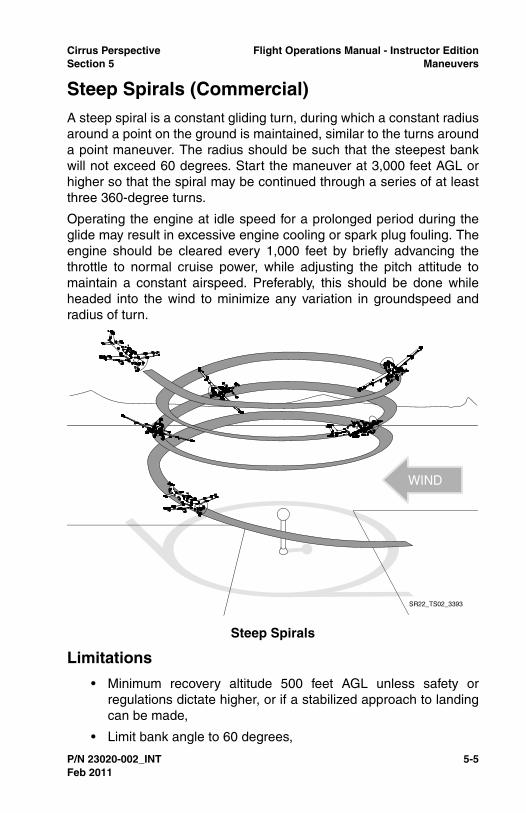
Cirrus Perspective Flight Operations Manual - Instructor EditionSection 5 Maneuvers
P/N 23020-002_INT 5-5
Steep Spirals (Commercial)A steep spiral is a constant gliding turn, during which a constant radiusaround a point on the ground is maintained, similar to the turns arounda point maneuver. The radius should be such that the steepest bankwill not exceed 60 degrees. Start the maneuver at 3,000 feet AGL orhigher so that the spiral may be continued through a series of at leastthree 360-degree turns.
Operating the engine at idle speed for a prolonged period during theglide may result in excessive engine cooling or spark plug fouling. Theengine should be cleared every 1,000 feet by briefly advancing thethrottle to normal cruise power, while adjusting the pitch attitude tomaintain a constant airspeed. Preferably, this should be done whileheaded into the wind to minimize any variation in groundspeed andradius of turn.
Limitations
• Minimum recovery altitude 500 feet AGL unless safety orregulations dictate higher, or if a stabilized approach to landingcan be made,
• Limit bank angle to 60 degrees,
Steep Spirals
WIND
SR22_TS02_3393
Feb 2011

5-6 P/N 23020-002_INT
Flight Operations Manual - Instructor Edition Cirrus PerspectiveManeuvers Section 5
• Limited to VMC.
Execution
• Reduce throttle to idle,
• Adjust aircraft pitch to maintain altitude until VG is reached,
• Lower nose to maintain VG over the selected reference point,
• Adjust bank angle as necessary to fly a constant radius overselected reference point.
• Clear engine every 1,000 feet,
• Complete a minimum of at least three, 360-degree turns.
Recovery
• Add power as necessary and climb to desired altitude, or
• Continue landing if a stabilized approach to landing can bemaintained.
Instructor Notes
Completing a steep spiral to a stabilized approach and landing is agood way to develop skills necessary to conduct emergency landings.Conduct this maneuver during commercial pilot training and whencompleting recurrent training or a flight review with pilots.
The pilot should be in charge of clearing the engine during thismaneuver. It is also beneficial to have the pilot control radiocommunication if the maneuver will be conducted over an airport.
Completion Standards
• Selects an altitude sufficient to continue through a series of atleast three 360-degree turns,
• Selects a suitable ground reference point,
• Applies wind-drift correction to track a constant radius circlearound the selected reference point with bank not to exceed 60degrees,
• Divides attention between airplane control and ground track,while maintaining coordinated flight,
• Maintains VG +/-10 KIAS, rolls out toward object or specifiedheading +/- 10 degrees,
Feb 2011

Cirrus Perspective Flight Operations Manual - Instructor EditionSection 5 Maneuvers
P/N 23020-002_INT 5-7
• Positions aircraft for a stabilized approach to landing andcompletes a power-off landing within applicable completionstandards.
Common Errors
• Fails to maintain constant airspeed resulting in ground speedchanges and difficulty maintaining a constant radius,
• Fails to decrease bank angle sufficiently on the upwind side toprevent getting blown over the reference point,
• Fails to account for wind changes throughout the descent,
• Mis-judges descent rate and fails to position the aircraft for astabilized approach to landing if a landing was attempted.
Feb 2011
5-8 P/N 23020-002_INT
Flight Operations Manual - Instructor Edition Cirrus PerspectiveManeuvers Section 5
Chandelle (Commercial)A chandelle is a maximum performance climbing turn beginning fromapproximately straight-and-level flight, and ending at the completion ofa precise 180 degree turn in a wings-level, nose-high attitude at theminimum controllable airspeed. The maneuver demands that themaximum flight performance of the airplane be obtained; the airplaneshould gain the most altitude possible for a given degree of bank andpower setting without stalling.
Since numerous atmospheric variables beyond control of the pilot willaffect the specific amount of altitude gained, the quality of theperformance of the maneuver is not judged solely on the altitude gain,but by the pilot’s overall proficiency as it pertains to climb performancefor the power and bank combination used, and to the elements ofpiloting skill demonstrated.
Prior to starting a chandelle, the flaps should be in the UP position,power set for 120 KIAS, and the airspace behind and above clear ofother air traffic. The maneuver should be entered from straight-and-level flight at 120 KIAS. After the appropriate airspeed and powersetting have been established, the chandelle is started by smoothlyentering a coordinated turn with an angle of bank appropriate for theairplane being flown. Increase to full power as the climb is initiated.
Normally, this angle of bank should not exceed approximately 30degrees. After the appropriate bank is established, a climbing turnshould be started by smoothly applying back-elevator pressure toincrease the pitch attitude at a constant rate and to attain the highestpitch attitude as 90 degrees of the turn is completed. Apply rudderinputs to maintain coordinated flight throughout the maneuver.
Feb 2011

Cirrus Perspective Flight Operations Manual - Instructor EditionSection 5 Maneuvers
P/N 23020-002_INT 5-9
Limitations
• Minimum recovery altitude 1,500 feet AGL
• Limited to VMC.
Execution
• Clear area around and above the aircraft,
• Maintain and note heading,
• Establish level flight at 120 KIAS,
• SR20 - 60% Power / 21" MP (approximately),
• SR22 - 30% Power / 18" MP (approximately),
• SR22TN - 55% Power / 20" MP (approximately),
• SR22T - 50% Power / 18” MP (approximately).
• Enter coordinated 30 degree level turn,
• Increase pitch at a constant rate to achieve max pitch halfwaythrough the 180-degree turn while simultaneously adding fullpower,
Chandelle
SR22_TS02_3394
Feb 2011
5-10 P/N 23020-002_INT
Flight Operations Manual - Instructor Edition Cirrus PerspectiveManeuvers Section 5
• At the 90-degree point in the turn, maintain maximum pitchattitude while decreasing angle of bank at a constant rate to rollout wings level 180-degrees from starting heading,
• Hold the maximum pitch attitude momentarily at the 180-degree point, then reduce pitch to maintain level flight.
Recovery
• Reduce power to normal cruise power setting once aircraft hasaccelerated as desired.
Instructor Notes
Pilots often have difficulty maintaining coordinated flight during thismaneuver due to the constantly changing airspeed and ruddereffectiveness. It may be beneficial to limit power addition untilcoordination can be maintained. Be sure to practice this maneuverwith turns in both directions due to the differences in rudder controlinputs required and visual sight picture. Start the maneuver on acardinal direction in a area with visual direction indicators if possible.
Completion Standards
• Starts and completes maneuver higher than 1,500 feet AGL,
• Enters the maneuver at 120 KIAS with flaps UP,
• Establishes a 30-degree left or right turn,
• Simultaneously applies power and pitch to maintain a smooth,coordinated climbing turn to the 90-degree point, with aconstant bank angle,
• Begins a coordinated constant rate rollout from the 90-degreepoint to the 180-degree point maintaining full power and aconstant pitch attitude,
• Completes rollout at the 180-degree point +/-10 degrees, justabove a stall airspeed, and maintaining that airspeedmomentarily while avoiding a stall,
• Resumes straight-and-level flight with a minimum loss ofaltitude.
Common Errors
• Establishes a maximum pitch that is too great, resulting in astall condition,
Feb 2011

Cirrus Perspective Flight Operations Manual - Instructor EditionSection 5 Maneuvers
P/N 23020-002_INT 5-11
• Fails to maintain coordination throughout maneuver,
• Fails to maintain a constant rate of pitch or bank changesduring the appropriate phases of the maneuver,
• Fails to divide attention and look outside at visual referencepoints.
Feb 2011
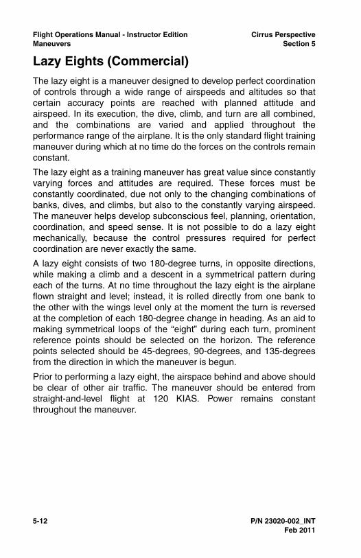
5-12 P/N 23020-002_INT
Flight Operations Manual - Instructor Edition Cirrus PerspectiveManeuvers Section 5
Lazy Eights (Commercial)The lazy eight is a maneuver designed to develop perfect coordinationof controls through a wide range of airspeeds and altitudes so thatcertain accuracy points are reached with planned attitude andairspeed. In its execution, the dive, climb, and turn are all combined,and the combinations are varied and applied throughout theperformance range of the airplane. It is the only standard flight trainingmaneuver during which at no time do the forces on the controls remainconstant.
The lazy eight as a training maneuver has great value since constantlyvarying forces and attitudes are required. These forces must beconstantly coordinated, due not only to the changing combinations ofbanks, dives, and climbs, but also to the constantly varying airspeed.The maneuver helps develop subconscious feel, planning, orientation,coordination, and speed sense. It is not possible to do a lazy eightmechanically, because the control pressures required for perfectcoordination are never exactly the same.
A lazy eight consists of two 180-degree turns, in opposite directions,while making a climb and a descent in a symmetrical pattern duringeach of the turns. At no time throughout the lazy eight is the airplaneflown straight and level; instead, it is rolled directly from one bank tothe other with the wings level only at the moment the turn is reversedat the completion of each 180-degree change in heading. As an aid tomaking symmetrical loops of the “eight” during each turn, prominentreference points should be selected on the horizon. The referencepoints selected should be 45-degrees, 90-degrees, and 135-degreesfrom the direction in which the maneuver is begun.
Prior to performing a lazy eight, the airspace behind and above shouldbe clear of other air traffic. The maneuver should be entered fromstraight-and-level flight at 120 KIAS. Power remains constantthroughout the maneuver.
Feb 2011
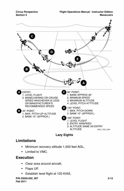
Cirrus Perspective Flight Operations Manual - Instructor EditionSection 5 Maneuvers
P/N 23020-002_INT 5-13
Limitations
• Minimum recovery altitude 1,500 feet AGL,
• Limited to VMC.
Execution
• Clear area around aircraft,
• Flaps UP,
• Establish level flight at 120 KIAS,
Lazy Eights
SR22_TS02_3392
ENTRY:1. LEVEL FLIGHT2. MANEUVERING OR CRUISE SPEED WHICHEVER IS LESS OR MANUFACTURER"S RECOMMENDED SPEED
180° POINT:1. LEVEL FLIGHT2. ENTRY AIRSPEED3. ALTITUDE SAME AS ENTRY ALTITUDE
90° POINT:1. BANK APPROX 30°2. MINIMUM SPEED3. MAXIMUM ALTITUDE4. LEVEL PITCH ATTITUDE
45° POINT:1. MAX. PITCH-UP ALTITUDE2. BANK 15° (APPROX.)
135° POINT:1. MAX. PITCH-DOWN2. BANK 15° (APPROX.)
Feb 2011

5-14 P/N 23020-002_INT
Flight Operations Manual - Instructor Edition Cirrus PerspectiveManeuvers Section 5
• SR20 - 60% Power / 21" MP (approximately),
• SR22 - 30% Power / 18" MP (approximately),
• SR22TN - 55% Power / 20" MP (approximately),
• SR22T - 50% Power / 18” MP (approximately).
• Control the aircraft to achieve the following throughout themaneuver,
• At the 45-degree reference, maximum pitch up attitude withapproximately 15 degrees of bank,
• At the 90-degree reference, maximum bank of 30 degreeswith level pitch,
• At the 135-degree reference, maximum pitch down attitudewith approximately 15 degrees of bank,
• At the 180-degree point, momentary level pitch and bank asthe turn direction is changed,
• Proper coordination,
• Constantly changing pitch and roll rates.
Recovery
• Apply power as necessary to resume normal flight.
Instructor Notes
Pilots tend to rush through lazy eights or ‘force’ the maneuver tohappen. This usually results in frozen pitch or roll rates or attitudesbecause the aircraft arrives at desired pitch or roll attitude before theintended reference point. Pilots should trim the aircraft before the startof the maneuver and use light forces on the control stick. A firm grip onthe yoke usually results in the pilot over controlling the aircraft.Defining reference points before starting the maneuver is crucial.Ensure that pilots are dividing their attention between instrument scanand outside visual reference. The majority of scan time should bespent looking outside the aircraft.
Completion Standards
• Establishes the recommended entry configuration, power, andairspeed,
• Maintains altitude tolerance at 180-degree points, +/-100 feetfrom entry altitude,
Feb 2011

Cirrus Perspective Flight Operations Manual - Instructor EditionSection 5 Maneuvers
P/N 23020-002_INT 5-15
• Maintains airspeed tolerance at the 180-degree point, +/-10KIAS from entry airspeed,
• Maintains heading tolerance at the 180-degree point, +/- 10degrees,
• Continues the maneuver through the number of symmetricalloops specified and resumes straight and level flight.
Common Errors
• Rushes through maneuver and requires non-constant rates ofpitch or roll change to match desired reference points,
• Fails to monitor area for other traffic during maneuver,
• Uses erratic or rough control inputs, usually caused by attemptsto counteract poor planning.
Feb 2011

5-16 P/N 23020-002_INT
Flight Operations Manual - Instructor Edition Cirrus PerspectiveManeuvers Section 5
Maneuvering during Slow FlightPractice this maneuver with a variety of flap configurations whileclimbing, descending, and turning. Enter the maneuver in level flightand smoothly reduce power. Maintain altitude while the aircraft slowsto the desired airspeed and trim the aircraft. Add flaps as desired atVFE. Add power as necessary to maintain the desired altitude.Maintain coordination throughout the maneuver with rudder control.Recover from this maneuver if a stall is encountered.
Limitations
• Minimum recovery altitude: 1,500 feet AGL,
• Limited to VMC.
Execution
• Execute clearing turns,
• Reduce power,
• SR20 - 20% Power / 15" MP (approximately),
• SR22 - 15% Power / 12" MP (approximately),
• SR22TN - 25% Power / 12” MP (approximately),
• SR22T - 30% Power / 12.5” MP (approximately).
• Flaps as desired (0% - 100%),
• Bank angle as desired (20º maximum),
• Airspeed - an airspeed at which any further increase in angle ofattack, increase in load factor, or reduction in power wouldresult in an immediate stall (current PTS standards),
• Power as required for level flight or desired climb or descentrate.
Recovery
• Reduce angle of attack and level wings,
• Apply full power,
• Flaps 50%,
• Accelerate to VY,
• Flaps 0%,
• SR20 - 85 KIAS,
Feb 2011

Cirrus Perspective Flight Operations Manual - Instructor EditionSection 5 Maneuvers
P/N 23020-002_INT 5-17
• SR22 - 80 KIAS.
• Clear of terrain and obstacles,
• Positive rate of climb.
Instructor Notes
Maneuvering during slow flight is an excellent maneuver to performand master before attempting takeoff and landing practice. Emphasizeprecise airspeed control, pre-stall recognition, rudder coordination,and division of attention during this maneuver.
Have the pilot practice this maneuver in different configurations,making the correlation to traffic pattern operations and proper round-out and flare attitudes.
Be aware of rudder inputs made by the pilot during the maneuver.Pilots often neglect to apply rudder inputs during power additions whilein slow flight.
Completion Standards
• Exhibits knowledge of the elements related to this maneuverand complies with limitations, execution, and recoveryprocedures described in this manual,
• (Private) Maintains altitude +/-100 feet, airspeed +10/-0 KIAS,bank angle +/- 10 degrees, desired heading +/-10 degrees,
• (Commercial) Maintains altitude +/-50 feet, airspeed +5/-0KIAS, bank angle +/-5 degrees, desired heading +/-10 degrees,
• Accomplishes coordinated straight-and-level flight, turns,climbs, and descents with flap configurations specified by theinstructor,
• Divides attention between visual references and instrumentscan.
Common Errors
• Fails to maintain coordination during maneuver,
• Fails to recognize the signs of an impending stall,
• Fails to understand and apply proper power and pitch controlinputs when changing or correcting airspeed and/or altitudedeviations.
Feb 2011

5-18 P/N 23020-002_INT
Flight Operations Manual - Instructor Edition Cirrus PerspectiveManeuvers Section 5
Power-Off StallsPractice this maneuver with varying flap configurations. Enter thismaneuver from a level attitude by reducing the power and adding flapsas desired at VFE. At 80 KIAS establish a descent of approximately500 FPM, straight or turning. Once a stabilized descent is established,reduce power to idle and gradually increase pitch to a normaltouchdown attitude (7.5 degrees approximately). Adjust pitch toreduce airspeed approximately 1 KIAS / second. Recovery can beinitiated at the incipient phase or full stall.
Limitations
• Minimum recovery altitude: 1,500 feet AGL,
• Limited to VMC.
Execution
• Execute clearing turns,
• Flaps as desired (0% - 100%),
• Establish glide or gliding turn slowing to 80 KIAS,
• SR20 - 20% Power / 15" MP (approximately),
• SR22 - 15% Power / 12" MP (approximately),
• SR22TN - 25% Power / 12" MP (approximately),
• SR22T - 30% Power / 12.5” MP (approximately).
• Descent rate 500 fpm (approximately),
• 20º max bank angle,
• Reduce throttle to idle and increase pitch to a normal landingattitude (5º to 7.5º) and induce a stall.
Recovery
• Reduce angle of attack and level wings,
• Apply full power,
• Flaps 50%,
• Accelerate to VY,
• Flaps 0%,
• Airspeed 80 KIAS (SR22) 85 KIAS (SR20),
• Clear of terrain and obstacles,
Feb 2011

Cirrus Perspective Flight Operations Manual - Instructor EditionSection 5 Maneuvers
P/N 23020-002_INT 5-19
• Positive rate of climb.
Instructor Notes
It is useful to make a correlation between a power-off stall setup andtraffic pattern operations. Start on a heading and slow to traffic patternspeeds. Next, reduce power and add approach flaps to simulate beingabeam the desired touchdown point. Start a 30-degree-bank turnwhile in a controlled descent and slow to 90 KIAS. Add full flaps andslow to 80 KIAS while continuing to descend. Turn another 90 degreesto simulate turning final approach and start reducing throttle andincreasing back pressure to simulate round-out and flare. Holdelevator back pressure to induce a stall with the power at idle.
Initially, recover at the incipient phases while highlighting signs of theimpending stall to develop stall recognition skills. This provides a goodopportunity for go-around practice. Once stall recognition skills aredeveloped and the pilot’s recovery technique is correct, practicerecovering from a full-stall condition. Practice recovering from straightor turning flight, with a maximum of 20 degrees of bank.
Highlight proper rudder control inputs during stall recovery. Pilots oftenneglect to apply sufficient rudder input while applying go-aroundpower.
Completion Standards
• Exhibits knowledge of the elements related to this maneuverand complies with limitations, execution, and recoveryprocedures described in this manual,
• Describes factors that affect stall speed and situations whereunintentional stalls are likely to occur,
• Transitions smoothly from the approach or landing attitude to apitch attitude that will induce a stall,
• (Private) Maintains a specified heading +/-10 degrees instraight flight, maintains a specified angle of bank not to exceed20 degrees, angle of bank +/-10 degrees in turning flight whileinducing stall,
• (Commercial) Maintains a specified heading +/-10 degrees instraight flight, maintains a specified angle of bank not to exceed20 degrees, angle of bank +/-5 degrees in turning flight whileinducing stall,
Feb 2011
5-20 P/N 23020-002_INT
Flight Operations Manual - Instructor Edition Cirrus PerspectiveManeuvers Section 5
• Recognizes and recovers promptly after the stall occurs bysimultaneously reducing the angle of attack, increasing powerto maximum allowable, and leveling the wings to return to astraight-and-level flight attitude with a minimum loss of altitude,
• Retracts flaps from 100% to 50% once the descent has beenstopped and then retracts flaps from 50% to 0% once a positiverate of climb is established with airspeed at or above thatrecommended,
• Returns to the previous altitude, heading, and airspeedspecified by the instructor.
Common Errors
• Fails to add sufficient rudder input during stall recovery,
• Retracts flaps prematurely during recovery, resulting inexcessive loss of altitude,
• Fails to promptly apply full power resulting in an excessive lossof altitude and/or delayed recovery,
• Increases pitch excessively, resulting in a secondary orunintentional stall.
Feb 2011

Cirrus Perspective Flight Operations Manual - Instructor EditionSection 5 Maneuvers
P/N 23020-002_INT 5-21
Power-On StallsPractice this maneuver with 0% and/or 50% flaps, straight and turning.Enter the maneuver from level flight by reducing power and addingflaps as desired at VFE. Slow the aircraft to VR while maintainingaltitude. At VR smoothly apply a minimum of 65% power and pitch theaircraft at an angle to induce a stall. Apply rudder to maintaincoordination. Recover from this maneuver at the incipient phase or fullstall.
Limitations
• Minimum recovery altitude: 1,500 feet AGL,
• Limited to VMC,
• Limit nose high attitude to 30 degrees as per Private andCommercial Practical Test Standards,
• Minimum percent power is 65%
Execution
• Execute clearing turns,
• Flaps 0% or 50% as desired,
• Airspeed- slow to VR,
• SR20 - 20% Power / 15" MP (approximately),
• SR22 - 15% Power / 12" MP (approximately),
• SR22TN - 25% Power / 12" MP (approximately),
• SR22T - 30% Power / 12.5” MP (approximately).
• Bank angle as desired (20 degrees maximum),
• Apply a minimum of 65% power,
• Increase pitch angle to induce stall (maximum 30-degrees pitchattitude).
Recovery
• Reduce angle of attack and level wings,
• Verify full power,
• Accelerate to VY,
• Flaps 0%,
Feb 2011

5-22 P/N 23020-002_INT
Flight Operations Manual - Instructor Edition Cirrus PerspectiveManeuvers Section 5
• Airspeed 80 KIAS (SR22) 85 KIAS (SR20),
• Clear of terrain and obstacles,
• Positive rate of climb.
Instructor Notes
Power-on stalls simulate a stalled condition during initial climb, enrouteclimb, or climb-out from a go-around or missed approach. Practicepower-on stalls in 50% and 0% flaps conditions. It is recommended tocomplete 0% flap power-on stalls at a reduced power setting to keeppitch attitudes below 30-degrees nose high.
Proper rudder inputs and coordination is crucial during operations athigh angles of attack and high power settings. Ensure pilots applyproper rudder inputs throughout the maneuver.
Completion Standards
• Exhibits knowledge of the elements related to this maneuverand complies with limitations, execution and recoveryprocedures described in this manual,
• (Private) Maintains a specified heading within +/-10 degrees instraight flight, and a specified angle of bank (less than 20degrees) within +/-10 degrees,
• (Commercial) Maintains a specified heading within +/-5degrees in straight flight, and a specified angle of bank (lessthan 20 degrees) within +/-10 degrees,
• Recognizes and recovers promptly after the stall occurs bysimultaneously reducing the angle of attack, increasing poweras appropriate, and leveling the wings to return to a straight-and-level flight attitude with a minimum loss of altitude,
• Retracts flaps from 50% to 0% when the aircraft has resumed aclimb at or above the recommended flap retraction airspeed.
Common Errors
• Fails to apply proper rudder inputs to maintain coordinationduring maneuver,
• Reduces pitch attitude too much during recovery, causing anexcessive loss of altitude,
Feb 2011

Cirrus Perspective Flight Operations Manual - Instructor EditionSection 5 Maneuvers
P/N 23020-002_INT 5-23
• Fails to maintain heading within standards through properrudder and aileron inputs during maneuver, setup, andrecovery.
• Exhibits a lack of knowledge of elements related to spinsprevention and spin recovery.
Feb 2011
5-24 P/N 23020-002_INT
Flight Operations Manual - Instructor Edition Cirrus PerspectiveManeuvers Section 5
Autopilot Stall RecognitionThe purpose of this maneuver is to identify the conditions when a stallwith the autopilot engaged may occur, to recognize the effects of animpending autopilot stall, and to learn the recovery procedure. Do notexceed any autopilot limitations during this maneuver. The maneuveris started by programming the autopilot for conditions it is not capableof maintaining (excessive climb rate, insufficient power, etc). Autopilotswith Perspective software load 764.09 or later have low-speedprotection and respond differently then previous software loads. Whilesoftware loads 764.08 and prior disconnect the autopilot below 80KIAS, later loads will remain engaged and will switch mode priorities tomaintain a flying airspeed above the stall speed.
Regardless of the software load, the highest priority is to regainaircraft control by decreasing the angle of attack and increasingairspeed. Reference the correct section below for maneuver setup andexecution depending on the Perspective software load.
Limitations
• Minimum recovery altitude: 1,500 feet AGL,
• Limited to VMC,
• All autopilot limitations in the AFM apply.
Execution
• Execute clearing turns,
• Flaps as desired,
• Autopilot lateral and pitch modes as desired,
• Throttle insufficient for sustained flight.
Recovery for Software Load 764.09 or later
• Smoothly apply full throttle, and
• Verify and maintain aircraft coordination,
• Reduce throttle as necessary once normal flight is resumed.
Recovery for Software Load 764.08 or prior
• Disconnect autopilot and simultaneously:
• Reduce angle of attack,
• Increase throttle as required,
Feb 2011

Cirrus Perspective Flight Operations Manual - Instructor EditionSection 5 Maneuvers
P/N 23020-002_INT 5-25
• Level wings,
• After initial recovery, return aircraft to previously assignedheading, altitude, or desired flight condition.
Instructor Notes
Verify Perspective software loads before attempting the autopilot stallrecognition maneuver and follow the applicable guidance.
Pilots may get into a slow flight or stalled condition with the autopilotengaged for many reasons. Pilot complacency, inattentiveness, andpower mis-management are major reason why pilots may end up‘behind the power curve’ with the autopilot engaged. It is common tosee this situation during periods of high workload, such as on a non-precision approach with multiple step-downs or climbing throughturbulent clouds shortly after takeoff during an IFR departure.
Regardless of pilot workload, pilots must always maintain aircraftcontrol through proper instrument scan and interpretation. Scanintervals may be reduced with the autopilot engaged, allowing moretime for task completion, but the scan should never be abandonedcompletely. Pilots must be taught to focus attention on aircraft controlwhen overwhelmed with workload and/or stress.
It is possible to enter the autopilot stall recognition maneuver a fewdifferent ways. Draw correlation to specific phases of flight where anautopilot stall is likely. Here are a few maneuver setup examples:
• Simulate a level-off on an approach by entering a descent at120 KIAS at a constant rate to a desired altitude. Intentionallyneglect to restore power to maintain airspeed upon level-off,
• Program an excessive rate of climb with an insufficient powersetting. This provides a good example of why climbing in IASmode is recommended,
• Software loads 764.09 or later: press the go-around button andleave power at or near idle.
Completion Standards
• Describes situations likely to lead to an autopilot stall or under-speed condition,
• Exhibits knowledge of the elements related to autopilot stallsand complies with limitations, execution and recoveryprocedures described in this manual,
Feb 2011

5-26 P/N 23020-002_INT
Flight Operations Manual - Instructor Edition Cirrus PerspectiveManeuvers Section 5
• Recognizes and promptly corrects from an impending autopilotstall or slow flight condition,
• Minimizes loss of altitude by applying proper power inputs andcontrols aircraft pitch as necessary,
• Returns to previously assigned or desired flight parameters andadvises ATC of any inability to maintain an ATC clearance.
Common Errors
• Lacks knowledge of autopilot limitations,
• Becomes complacent and neglects to actively scan andmonitor flight status during autopilot operations,
• Fails to verify active and armed autopilot modes,
• Fails to manage power required to maintain the desiredairspeed and/or altitude.
Feb 2011

Cirrus Perspective Flight Operations Manual - Instructor EditionSection 5 Maneuvers
P/N 23020-002_INT 5-27
Ground Reference ManeuversGround reference maneuvers described in this section are required byPrivate Pilot and Commercial Practical Test Standards. Practicingthese maneuvers helps pilots develop fundamental skills of aircraftcontrol, division of attention, and correction for wind drift. The skillsdeveloped while performing these maneuvers have real-lifeapplicability and are the basis for many flight operations performedduring normal day-to-day flight operations. Rated pilots shouldpractice these maneuvers to hone skills during recurrent trainingevents and flight reviews.
Complete ground reference maneuvers in an area with an availableemergency landing spot. Do not practice ground reference maneuversin a noise sensitive area. Be sure to avoid areas with towers orcongested traffic.
The decision to deploy CAPS must be made immediately below 2,000feet AGL. Pre-brief if CAPS will be a viable option to increase survivalpotential if a catastrophic engine failure is experienced during groundreference maneuvers.
It may be beneficial to inhibit TAWS during ground referencemaneuvers to reduce cockpit distractions. Ensure the area is free ofobstacle or terrain hazards before inhibiting TAWS. Remember to un-inhibit TAWS at the maneuver completion.
Limitations
• Limited to VMC,
• Minimum altitude 600 feet AGL,
• Within all other regulatory altitude restrictions,
• Within a position to make an emergency landing.
Feb 2011

5-28 P/N 23020-002_INT
Flight Operations Manual - Instructor Edition Cirrus PerspectiveManeuvers Section 5
Rectangular Course (Private)Select a rectangular area approximately one mile in length by aminimum of 1/2 mile wide. Enter the maneuver 45 degrees to thedownwind at 1,000 feet AGL. Fly a ground track which is equidistantfrom all sides of the rectangular area while accounting for wind driftand maintaining constant airspeed and altitude.
Practice this maneuver using an actual runway traffic pattern at anuncontrolled airport with no traffic conflicts when developing basictraffic pattern skills and wind drift correction skills.
Execution
• Execute clearing turns,
• Airspeed 100 KIAS,
• SR20 - 50% Power / 20" MP (approximately),
• SR22 - 30% Power / 15" MP (approximately),
Rectangular Course
Feb 2011

Cirrus Perspective Flight Operations Manual - Instructor EditionSection 5 Maneuvers
P/N 23020-002_INT 5-29
• SR22TN - 50% Power / 15" MP (approximately),
• SR22T - 40% Power / 15” MP (approximately).
• Enter on the downwind leg at a 45-degree angle,
• Maintain approximately 1/2 mile from the reference line.
Recovery
• Add power as necessary and climb to a desired altitude.
Instructor Notes
Conduct the maneuver as low as 600 feet AGL if the pilot is unable torecognize and control wind drift. Maintain defensive positions on theflight, throttle, and rudder controls and take over aircraft control toavoid excessive descent rates due to over-banking or possible birdstrike situations. This maneuver is not required during Cirrus coursesbut may be conducted at the discretion of the pilot or instructor if thepilot lacks basic traffic pattern and wind-drift correction skills.
Completion Standards
• Selects a suitable area to perform the maneuver consideringemergency landing availability, noise abatement, and obstacleand terrain clearance,
• Applies adequate wind-drift correction during straight-and-turning flight to maintain a constant ground track around therectangular reference area,
• Divides attention between aircraft control and ground trackwhile maintaining coordinated flight,
• Maintains altitude, +/-100 feet, airspeed +/-10 KIAS.
Common Errors
• Fails to apply proper rudder inputs to maintain coordinatedflight during the maneuver,
• Fails to clear the area for traffic, terrain, or obstacle hazards,
• Over controls pitch and roll excessively and exceedsperformance standards,
• Fails to plan and anticipate wind correction for future segments,
• Displays an inability to quickly scan airspeed and altitudeinstrumentation.
Feb 2011
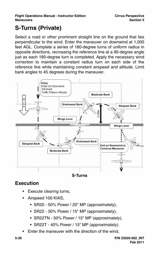
5-30 P/N 23020-002_INT
Flight Operations Manual - Instructor Edition Cirrus PerspectiveManeuvers Section 5
S-Turns (Private)Select a road or other prominent straight line on the ground that liesperpendicular to the wind. Enter the maneuver on downwind at 1,000feet AGL. Complete a series of 180-degree turns of uniform radius inopposite directions, recrossing the reference line at a 90-degree anglejust as each 180-degree turn is completed. Apply the necessary windcorrection to maintain a constant radius turn on each side of thereference line while maintaining constant airspeed and altitude. Limitbank angles to 45 degrees during the maneuver.
Execution
• Execute clearing turns,
• Airspeed 100 KIAS,
• SR20 - 50% Power / 20" MP (approximately),
• SR22 - 30% Power / 15" MP (approximately),
• SR22TN - 50% Power / 15" MP (approximately),
• SR22T - 40% Power / 15” MP (approximately).
• Enter the maneuver with the direction of the wind,
S-Turns
Feb 2011

Cirrus Perspective Flight Operations Manual - Instructor EditionSection 5 Maneuvers
P/N 23020-002_INT 5-31
• Maintain approximately 1/2 mile radius from the reference line.
Recovery
• Add power as necessary and climb to a desired altitude.
Instructor Notes
Steep bank angles, up to 45 degrees, will be required to maintain thedesired flight path over the ground while performing S-turns on windydays. Closely guard the flight controls and ensure the pilot does notenter into an excessive descent rate when banking steeply during thismaneuver. Pilots that have difficulty making smooth and level pitchcontrol changes may be improperly scanning instruments or outsidereferences. Ensure pilots are quickly scanning airspeed and altitudeinstruments as necessary. However, the majority of time should bespent focusing vision forward and towards the next direction of turn.Focusing forward will allow the pilot to see the nose rising or fallingand will give the pilot better pitch and altitude control. It is also helpfulto practice this maneuver after the pilot has mastered steep turns.
Have the pilot verbalize his or her wind drift control strategies for up-and-coming turns. Doing this forces the pilot to think and plan ahead ofthe aircraft for future turns.
Pilots are typically caught off guard by the differences in bank anglesrequired between the upwind and downwind segments. This usuallyresults in the pilot banking excessively on the upwind segment andflying inside of the desired track. The aircraft will cross the referenceline prematurely and the pilot may attempt to over-bank to correct onthe downwind leg. Pilots that get too far ‘behind’ the maneuver shouldexit and restart.
Completion Standards
• Selects a suitable ground reference line perpendicular to thewind,
• Applies adequate wind-drift correction to track a constantradius turn on each side of the selected reference line,
• Reverses the direction of turn directly over the selectedreference line,
• Divides attention between airplane control and ground trackwhile maintaining coordinated flight,
• Maintains altitude, +/-100 feet, airspeed +/-10 KIAS,
Feb 2011

5-32 P/N 23020-002_INT
Flight Operations Manual - Instructor Edition Cirrus PerspectiveManeuvers Section 5
• Remains clear of all obstacles or terrain.
Common Errors
• Fails to apply proper rudder inputs to maintain coordinatedflight,
• Fails to clear area for traffic, terrain, or obstacle hazards,
• Over-controls pitch and roll excessively,
• Fails to plan and anticipate wind correction for future segments,
• Displays an inability to quickly scan airspeed and altitudeinstrumentation,
• Over-banks the aircraft and allows an excessive descent rate orsacrifices airspeed causing an accelerated stall condition.
Feb 2011

Cirrus Perspective Flight Operations Manual - Instructor EditionSection 5 Maneuvers
P/N 23020-002_INT 5-33
Turns Around a Point (Private)Find an area which will allow for safe execution of this maneuver andan available emergency landing area. Select a suitable, prominentground reference point. Enter the maneuver on downwind at 1,000 feetAGL. Fly two or more complete, uniform-radius circles around thereference point while compensating for wind drift and maintainingconstant airspeed and altitude. Limit bank angles to 45 degrees.
Execution
• Execute clearing turns,
• Airspeed 100 KIAS,
• SR20 - 50% Power / 20" MP (approximately),
• SR22 - 30% Power / 15" MP (approximately),
• SR22TN - 50% Power / 15" MP (approximately),
• SR22T - 40% Power / 15” MP (approximately).
• Enter with the wind and start a left or right turn,
Turns Around a Point
Feb 2011

5-34 P/N 23020-002_INT
Flight Operations Manual - Instructor Edition Cirrus PerspectiveManeuvers Section 5
• Maintain approximately 1/2 mile radius from reference point.
Recovery
• Add power as required and climb to desired altitude.
Instructor Notes
Mastering turns around a point before attempting steep spirals oremergency descents to landing is beneficial. Excessive bank angleswithout sufficient elevator back pressure leads to excessive descentrates. Closely guard flight controls to ensure pilots do not enterexcessive descent rates too close to the ground.
Completion Standards
• Selects a suitable ground reference point,
• Plans the maneuver so as to enter a left or a right turn at 1,000feet AGL, at an appropriate distance from the reference point,
• Applies adequate wind-drift correction to track a constantradius turn around the selected reference point,
• Divides attention between airplane control and ground trackwhile maintaining coordinated flight,
• Maintains altitude +/-100 feet, airspeed +/-10 KIAS.
Common Errors
• Fails to apply proper rudder inputs to maintain coordination,
• Fails to anticipate wind conditions for future segments,
• Banks excessively on the upwind segment of the maneuver,
• Fails to adjust pitch control while changing angles of bank,
• Focuses excessively inside the aircraft,
• Fails to scan for traffic during maneuver.
Feb 2011

Cirrus Perspective Flight Operations Manual - Instructor EditionSection 5 Maneuvers
P/N 23020-002_INT 5-35
Eight On Pylons (Commercial)Eights on pylons is the most advanced and most difficult of groundreference maneuvers. Because of the various techniques involved,eights on pylons is unsurpassed for teaching, developing, and testingsubconscious control of the airplane.
This training maneuver involves flying the airplane in circular paths,alternately left and right, in the form of a figure “eight” around twoselected points or pylons on the ground. Unlike eights around pylons,however, no attempt is made to maintain a uniform lateral distancefrom the pylon. In eights on pylons, the distance from the pylons variesif there is any wind. Instead, the airplane is flown at such a precisealtitude and airspeed that a line parallel to the airplane’s lateral axis,and extending from the pilot’s eye, appears to pivot on each of thepylons.
Also, unlike eights around pylons, in the performance of eights onpylons the degree of bank increases as the distance from the pylondecreases. The altitude that is appropriate for the airplane being flownis called the pivotal altitude and is governed by the groundspeed.While not truly a ground track maneuver as were the precedingmaneuvers, the objective is similar: to develop the ability to maneuverthe airplane accurately while dividing one’s attention between the flightpath and the selected points on the ground. In explaining theperformance of eights on pylons, the term “wing tip” is frequentlyconsidered as being synonymous with the proper reference line, orpivot point on the airplane. The selected pylons should also be at thesame elevation, since differences of over a very few feet willnecessitate climbing or descending between each turn.
Feb 2011

5-36 P/N 23020-002_INT
Flight Operations Manual - Instructor Edition Cirrus PerspectiveManeuvers Section 5
Execution
• Calculate approximate pivotal altitude (TAS squared anddivided by 11.3),
• Define visible ground reference points separated byapproximately 3/4 NM and perpendicular to the wind,
• Establish level flight at calculated pivotal altitude at 120 KIAS,
• SR20 - 60% Power / 21" MP (approximately),
• SR22 - 30% Power / 18" MP (approximately),
• SR22TN - 55% Power / 20" MP (approximately),
• SR22T - 50% Power / 18” MP (approximately).
• Cross diagonally between points with the wind so that the firstturn is made into the wind,
• Adjust angle of bank as required to maintain a sight line withthe reference point(s),
• Adjust pitch as required to maintain pivotal altitude, whichchanges with ground speed,
• Apply rudder as required to maintain coordination,
Eight On Pylons
WIN
D
SR22_TS02_3395
Feb 2011

Cirrus Perspective Flight Operations Manual - Instructor EditionSection 5 Maneuvers
P/N 23020-002_INT 5-37
• Complete the desired number of figure “eight” circuits aroundthe reference points.
Recovery
• Add power as required and climb to desired altitude.
Instructor Notes
As the eight on pylon is an advanced maneuver in which the pilot’sattention is directed at maintaining a pivotal position on a selectedpylon, with a minimum of attention within the cockpit, it should not beintroduced until the instructor is assured that the student has acomplete grasp of the fundamentals. The prerequisites are: the abilityto make a coordinated turn without gain or loss of altitude, excellentfeel of the airplane, stall recognition, relaxation with low altitudemaneuvering, and an absence of the error of over-concentration.
Completion Standards
• Describes elements related to pivotal altitude,
• Determines the approximate pivotal altitude,
• Enters the maneuver at the appropriate altitude and airspeedand at a bank angle of approximately 30 to 40 degrees at thesteepest point,
• Divides attention between accurate coordinated airplanecontrol and outside visual references,
• Holds pylon using appropriate pivotal altitude avoiding slips andskids.
Common Errors
• Exhibits inadequate knowledge relating to pivotal altitude, and/or ability to visualize maneuver,
• Makes a poor choice of ground reference points,
• Fails to consider surface winds, obstacles, emergency landingareas and/or traffic when defining ground reference points,
• Enters above or below calculated pivotal altitude,
• Uses rudder inputs to position the reference point on the pylon.
Feb 2011
5-38 P/N 23020-002_INT
Flight Operations Manual - Instructor Edition Cirrus PerspectiveManeuvers Section 5
Feb 2011
Intentionally Left Blank

Cirrus Perspective Flight Operations Manual - Instructor EditionSection 6 Performance
P/N 23020-002_INT 6-1
Section 6Performance
GeneralTo determine what performance to expect from the airplane undervarious ambient and field conditions, Refer to Section 5 - Performance,of the Pilot’s Operating Handbook. Performance data are presented fortakeoff, climb, and cruise (including range & endurance).
Feb 2011
6-2 P/N 23020-002_INT
Flight Operations Manual - Instructor Edition Cirrus PerspectivePerformance Section 6
Feb 2011
Intentionally Left Blank

Cirrus Perspective Flight Operations Manual - Instructor EditionSection 7 Limitations
P/N 23020-002_INT 7-1
Section 7Limitations
GeneralThe Limitations Section of the Pilot's Operating Handbook (POH) isthe official document approved by the Federal Aviation Administration.It provides operating limitations, instrument markings, basic placardsrequired by regulation, and standard systems and equipment requiredfor safe operation. For amended operating limitations for airplanesequipped with optional equipment, refer to Section 9 - Supplements ofthe Pilot’s Operating Handbook.
Compliance with the operating limitations in Pilot’s OperatingHandbook is required by Federal Aviation Regulations.
Feb 2011

7-2 P/N 23020-002_INT
Flight Operations Manual - Instructor Edition Cirrus PerspectiveLimitations Section 7
Feb 2011
Intentionally Left Blank