flight operations manual cirrus perspective avionics - pilot edition cirrus...
TRANSCRIPT
FLIGHT OPERATIONS MANUAL
CIR
RU
S P
ER
SP
EC
TIV
E A
VIO
NIC
S - P
ILOT
ED
ITIO
N
FLIGHT OPERATIONS MANUAL
CIR
RU
S P
ER
SP
EC
TIV
E A
VIO
NIC
S - C
OM
PA
NY
PILO
T E
DIT
ION
NOTEProcedures in this publication are derived from procedures in thefollowing FAA Approved Airplane Flight Manuals (AFM):• SR20, P/N 11934-004, Reissue A,• SR22, P/N 13772-004, Original Release,• SR22T, P/N 13772-005, Original Release.
Cirrus Aircraft has attempted to ensure that the data contained agreeswith the data in the respective AFM. If there is any disagreement, theAirplane Flight Manual is the final authority.
COPYRIGHT © 2013 CIRRUS DESIGN CORPORATION DULUTH, MINNESOTA, USAOriginal Release: February 2013
P/N 23020-003
Flight Operations ManualCompany Pilot Edition
Cirrus Perspective AvionicsSR20, SR22, SR22T
Original Issue.......... ................... Feb 2013
P/N 23020-003 LOEP-1
Cirrus Perspective Flight Operations ManualList of Effective Pages
List of Effective PagesUse this page to determine the current effective date for each page in the FOM.
Page Status Page Status Page StatusLOEP-1 Feb 2013LOEP-2 Feb 2013TOC-1 Feb 2013TOC-2 Feb 2013TOC-3 Feb 2013TOC-4 Feb 20131-1 Feb 20131-2 Feb 20131-3 Feb 20131-4 Feb 20131-5 Feb 20131-6 Feb 20131-7 Feb 20131-8 Feb 20131-9 Feb 20131-10 Feb 20131-11 Feb 20131-12 Feb 20131-13 Feb 20131-14 Feb 20131-15 Feb 20131-16 Feb 20131-17 Feb 20131-18 Feb 20131-19 Feb 20131-20 Feb 20131-21 Feb 20131-22 Feb 20131-23 Feb 20131-24 Feb 20132-1 Feb 20132-2 Feb 20132-3 Feb 20132-4 Feb 20132-5 Feb 20132-6 Feb 20132-7 Feb 20132-8 Feb 20132-9 Feb 20132-10 Feb 20132-11 Feb 20132-12 Feb 20132-13 Feb 20132-14 Feb 20132-15 Feb 20132-16 Feb 2013
2-17 Feb 20132-18 Feb 20132-19 Feb 20132-20 Feb 20132-21 Feb 20132-22 Feb 20132-23 Feb 20132-24 Feb 20132-25 Feb 20132-26 Feb 20132-27 Feb 20132-28 Feb 20132-29 Feb 20132-30 Feb 20132-31 Feb 20132-32 Feb 20132-33 Feb 20132-34 Feb 20132-35 Feb 20132-36 Feb 20132-37 Feb 20132-38 Feb 20132-39 Feb 20132-40 Feb 20133-1 Feb 20133-2 Feb 20133-3 Feb 20133-4 Feb 20133-5 Feb 20133-6 Feb 20133-7 Feb 20133-8 Feb 20133-9 Feb 20133-10 Feb 20133-11 Feb 20133-12 Feb 20133-13 Feb 20133-14 Feb 20133-15 Feb 20133-16 Feb 20133-17 Feb 20133-18 Feb 20133-19 Feb 20133-20 Feb 20133-21 Feb 20133-22 Feb 2013
3-23 Feb 20133-24 Feb 20133-25 Feb 20133-26 Feb 20133-27 Feb 20133-28 Feb 20133-29 Feb 20133-30 Feb 20133-31 Feb 20133-32 Feb 20133-33 Feb 20133-34 Feb 20133-35 Feb 20133-36 Feb 20133-37 Feb 20133-38 Feb 20133-39 Feb 20133-40 Feb 20133-41 Feb 20133-42 Feb 20133-43 Feb 20133-44 Feb 20133-45 Feb 20133-46 Feb 20133-47 Feb 20133-48 Feb 20133-49 Feb 20133-50 Feb 20133-51 Feb 20133-52 Feb 20133-53 Feb 20133-54 Feb 20133-55 Feb 20133-56 Feb 20133-57 Feb 20133-58 Feb 20133-59 Feb 20133-60 Feb 20133-61 Feb 20133-62 Feb 20133-63 Feb 20133-64 Feb 20133-65 Feb 20133-66 Feb 20133-67 Feb 20133-68 Feb 2013
Feb 2013
LOEP-2 P/N 23020-003
Cirrus Perspective Flight Operations ManualList of Effective Pages
List of Effective Pages (Cont.)
Page Status Page Status Page Status3-69 Feb 20133-70 Feb 20133-71 Feb 20133-72 Feb 20133-73 Feb 20133-74 Feb 20133-75 Feb 20133-76 Feb 20133-77 Feb 20133-78 Feb 20133-79 Feb 20133-80 Feb 20133-81 Feb 20133-82 Feb 20133-83 Feb 20133-84 Feb 20133-85 Feb 20133-86 Feb 20133-87 Feb 20133-88 Feb 20133-89 Feb 20133-90 Feb 20133-91 Feb 20133-92 Feb 20133-93 Feb 20133-94 Feb 20134-1 Feb 20134-2 Feb 20134-3 Feb 20134-4 Feb 20134-5 Feb 20134-6 Feb 20134-7 Feb 20134-8 Feb 20134-9 Feb 20134-10 Feb 20134-11 Feb 20134-12 Feb 20134-13 Feb 20134-14 Feb 20134-15 Feb 20134-16 Feb 20134-17 Feb 20134-18 Feb 20134-19 Feb 20134-20 Feb 20134-21 Feb 20134-22 Feb 20134-23 Feb 20134-24 Feb 20134-25 Feb 20134-26 Feb 20134-27 Feb 2013
4-28 Feb 20134-29 Feb 20134-30 Feb 20134-31 Feb 20134-32 Feb 20134-33 Feb 20134-34 Feb 20134-35 Feb 20134-36 Feb 20134-37 Feb 20134-38 Feb 20134-39 Feb 20134-40 Feb 20134-41 Feb 20134-42 Feb 20134-43 Feb 20134-44 Feb 20134-45 Feb 20134-46 Feb 20134-47 Feb 20134-48 Feb 20134-49 Feb 20134-50 Feb 20134-51 Feb 20134-52 Feb 20134-53 Feb 20134-54 Feb 20135-1 Feb 20135-2 Feb 20135-3 Feb 20135-4 Feb 20135-5 Feb 20135-6 Feb 20135-7 Feb 20135-8 Feb 20135-9 Feb 20135-10 Feb 20135-11 Feb 20135-12 Feb 20135-13 Feb 20135-14 Feb 20135-15 Feb 20135-16 Feb 20135-17 Feb 20135-18 Feb 20135-19 Feb 20135-20 Feb 20135-21 Feb 20135-22 Feb 20135-23 Feb 20135-24 Feb 20135-25 Feb 20135-26 Feb 2013
5-27 Feb 20135-28 Feb 20135-29 Feb 20135-30 Feb 20135-31 Feb 20135-32 Feb 20136-1 Feb 20136-2 Feb 20137-1 Feb 20137-2 Feb 2013
Feb 2013
P/N 23020-003 TOC-1
Cirrus Perspective Flight Operations ManualTable of Contents
Table of ContentsSection 1Introduction ....................................................................................1-1
General ...........................................................................................1-1Reference Materials ........................................................................1-2Terms and Abbreviations ................................................................1-3Contact Information.........................................................................1-5
Section 2General Operating Procedures .....................................................2-1
General ...........................................................................................2-1Pilot Qualification and Training .......................................................2-2Pilot Weather Minimums .................................................................2-8Pilot Duty and Rest Period ............................................................2-13Aircraft Maintenance and Airworthiness .......................................2-16Flight Planning ..............................................................................2-19Flight Considerations ....................................................................2-25Flight Safety ..................................................................................2-28Flying Club Procedures.................................................................2-30International Border Operations....................................................2-35Incident and Accident Procedures (U.S. Only) .............................2-37Aircraft Incident and Accident Report ...........................................2-38
Section 3Standard Operating Procedures ...................................................3-1
General ...........................................................................................3-1Single Pilot Resource Management................................................3-2Checklist Philosophy.......................................................................3-5Pre-Flight Inspection .......................................................................3-7Before Engine Start.......................................................................3-21Engine Start ..................................................................................3-23Before Taxi....................................................................................3-27Taxi-Out ........................................................................................3-29Before Takeoff ..............................................................................3-32Takeoff Briefing.............................................................................3-37Normal Takeoff .............................................................................3-38Short-Field Takeoff .......................................................................3-42Soft-Field Takeoff..........................................................................3-45
Feb 2013
TOC-2 P/N 23020-003
Cirrus Perspective Flight Operations ManualTable of Contents
Table of ContentsCrosswind Takeoff Technique.......................................................3-46Enroute Climb ...............................................................................3-47Cruise............................................................................................3-52Icing Conditions (FIKI)...................................................................3-54Descent .........................................................................................3-57Before Landing and Traffic Pattern ...............................................3-60Stabilized Approach Definition ......................................................3-64Instrument Approach Procedures .................................................3-66Precision Approach Procedure .....................................................3-68Nonprecision Approach Procedure ...............................................3-73Go-Around.....................................................................................3-78Approach and Landing Speeds.....................................................3-81Normal Landing.............................................................................3-82Short-Field Landing.......................................................................3-84Soft-Field Landing .........................................................................3-85Crosswind Landing........................................................................3-86Reduced Flap Landings (0% and 50%) ........................................3-87Icing Landing Procedure ...............................................................3-88After Landing.................................................................................3-90Arrival and Engine Shutdown........................................................3-92
Section 4Emergency & Abnormal Procedures ............................................4-1
General ...........................................................................................4-1Checklist Usage for Abnormal Procedures .....................................4-1Checklist Usage for Emergency Procedures ..................................4-1CAPS Deployment ..........................................................................4-2Emergency Descent ........................................................................4-7Engine Malfunctions Overview........................................................4-9Engine Failure In Flight .................................................................4-10Emergency Landing Without Engine Power..................................4-14Unexplained Loss of Manifold Pressure........................................4-17Engine Roughness or Partial Power Loss.....................................4-20Loss of Oil Pressure......................................................................4-22Engine Fire In Flight ......................................................................4-24Electrical Malfunctions Overview ..................................................4-27Alternator 1 and 2 Failures............................................................4-28
Feb 2013
P/N 23020-003 TOC-3
Cirrus Perspective Flight Operations ManualTable of Contents
Table of ContentsElectrical Fire (Cabin Fire In Flight)...............................................4-30Integrated Avionics Malfunctions Overview ..................................4-32PFD Display Failure and Reversionary Mode...............................4-34Air Data Computer Failure ............................................................4-36AHRS Failure ................................................................................4-38GIA Failure....................................................................................4-40Loss of GPS Integrity ....................................................................4-41Other Emergency Procedures Overview ......................................4-42Unusual Attitudes..........................................................................4-42Inadvertent Flight into IMC............................................................4-44Flap Malfunction............................................................................4-46Oxygen System Malfunction .........................................................4-47Power Lever Linkage Failure ........................................................4-49Loss of Brake Pressure.................................................................4-51Open Door ....................................................................................4-53
Section 5Maneuvers.......................................................................................5-1
General ...........................................................................................5-1Steep Turns (Private and Commercial)...........................................5-2Steep Spirals (Commercial) ............................................................5-4Chandelle (Commercial) .................................................................5-7Lazy Eights (Commercial) .............................................................5-10Maneuvering during Slow Flight....................................................5-14Power-Off Stalls ............................................................................5-16Power-On Stalls ............................................................................5-18Autopilot Stall Recognition ............................................................5-20Ground Reference Maneuvers......................................................5-22Rectangular Course (Private) .......................................................5-23S-Turns (Private)...........................................................................5-25Turns Around a Point (Private) .....................................................5-27Eight On Pylons (Commercial)......................................................5-29
Section 6Performance ...................................................................................6-1
General ...........................................................................................6-1
Section 7
Feb 2013
TOC-4 P/N 23020-003
Cirrus Perspective Flight Operations ManualTable of Contents
Table of ContentsLimitations ......................................................................................7-1
General ...........................................................................................7-1
Feb 2013
Cirrus Perspective Flight Operations Manual - Company Pilot EditionSection 1 Introduction
P/N 23020-003 1-1
Section 1Introduction
GeneralThe procedures in this publication are derived from procedures in theFAA Approved Airplane Flight Manual (AFM). Cirrus Aircraft hasattempted to ensure that the data contained herein agrees with thedata in the AFM. If there is any disagreement, the Airplane FlightManual is the final authority.
The Flight Operations Manual (FOM), Company Pilot Editiondescribes the policies and procedures for all flight conducted in aircraftthat are owned or operated by Cirrus Aircraft. Section 2 of thisdocument describes general operating procedures and trainingrequirements. Sections 3, 4, and 5 describe best practices foroperating Cirrus aircraft under visual or instrument flight regulations forstandard or typical circumstances considering normal and abnormal/emergency situations.
Pilot Responsibilities
Cirrus pilots conducting flights in Cirrus owned or operated aircraftmust adhere to the guidance contained herein. Pilots should exercisegood judgment and adapt the procedures as necessary to handle nonstandard or atypical situations.
Flight operations must be conducted with the utmost regard to safety,professionalism, and integrity. Negligent, careless, or recklessbehavior will not be tolerated and may result in flight restrictions, lossof flight privileges, or termination.
Each company pilot who is authorized to conduct flight operations inCirrus owned and operated aircraft will be issued a FOM, CompanyPilot Edition. The pilot must have this document in his or herpossession, printed or electronic version, during all flight operations ina Cirrus owned or operated aircraft.
This manual does not govern the operations conducted asExperimental Flight Test or Production Flight Test. However,experimental test pilots and production flight test pilots must adhere tothe policies and procedures described herein for all flights notconducted as experimental or flight test.
Feb 2013
1-2 P/N 23020-003
Flight Operations Manual - Company Pilot Edition Cirrus PerspectiveIntroduction Section 1
Revisions
The Director of Flight Operations is responsible to issue revisions tothis manual. Proposed changes must be reviewed by the leadership ofaffective departments and must be approved by Cirrus Aircraft seniorstaff. Desired changes, additions or deletions to this document shouldbe brought to the attention of the Director of Flight Operations.Additions or changes to this document will be distributed electronicallyuntil a significant number a changes warrants re-printing the newdocument. A new revision will supersede all previous revisions.
Reference MaterialsThe following references supplement the content of this publication:
• Federal Aviation Regulations (FARs) or governing regulations,as applicable,
• Aeronautical Information Manual (AIM),
• FAA Approved Airplane Flight Manual (AFM) and Pilot’sOperating Handbook (POH),
• FAA Handbook of Aeronautical Knowledge and Airplane FlyingHandbook,
• Advisory Circulars,
• Cirrus Aircraft Envelope of Safety,
• Cirrus Syllabus Suite,
• Avionics Pilot Guides and Manuals,
• Aircraft Maintenance Manual,
• Formation Flight Manual,
• Demo Care Inspection and Maintenance Program manual,
• Check Pilot Manual.
Feb 2013
Cirrus Perspective Flight Operations Manual - Company Pilot EditionSection 1 Introduction
P/N 23020-003 1-3
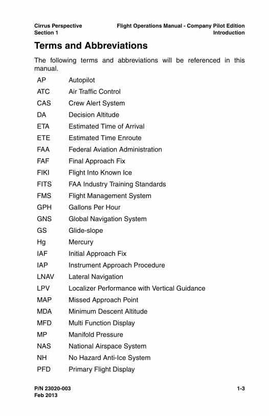
Terms and AbbreviationsThe following terms and abbreviations will be referenced in thismanual.
AP Autopilot
ATC Air Traffic Control
CAS Crew Alert System
DA Decision Altitude
ETA Estimated Time of Arrival
ETE Estimated Time Enroute
FAA Federal Aviation Administration
FAF Final Approach Fix
FIKI Flight Into Known Ice
FITS FAA Industry Training Standards
FMS Flight Management System
GPH Gallons Per Hour
GNS Global Navigation System
GS Glide-slope
Hg Mercury
IAF Initial Approach Fix
IAP Instrument Approach Procedure
LNAV Lateral Navigation
LPV Localizer Performance with Vertical Guidance
MAP Missed Approach Point
MDA Minimum Descent Altitude
MFD Multi Function Display
MP Manifold Pressure
NAS National Airspace System
NH No Hazard Anti-Ice System
PFD Primary Flight Display
Feb 2013
1-4 P/N 23020-003
Flight Operations Manual - Company Pilot Edition Cirrus PerspectiveIntroduction Section 1
PIC Pilot in Command
RPM Revolutions Per Minute
SRM Single Pilot Resource Management
VNAV Vertical Navigation
VTF Vectors to Final
WAAS Wide Area Augmentation System
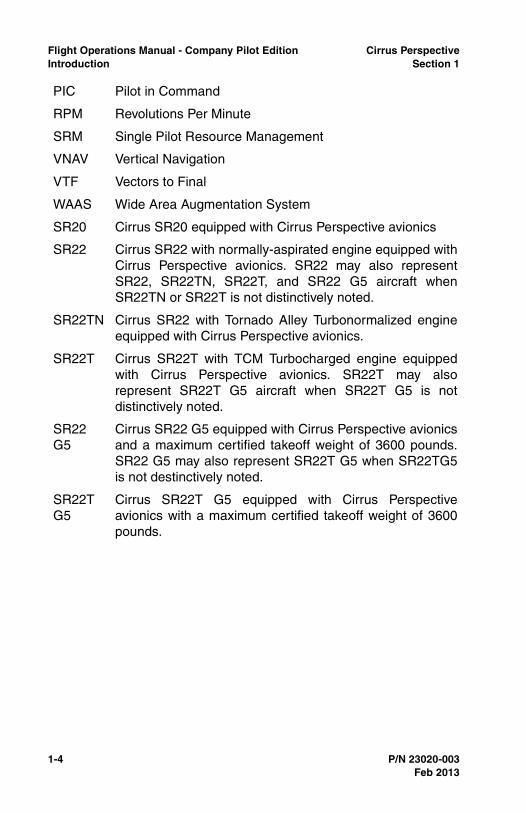
SR20 Cirrus SR20 equipped with Cirrus Perspective avionics
SR22 Cirrus SR22 with normally-aspirated engine equipped withCirrus Perspective avionics. SR22 may also representSR22, SR22TN, SR22T, and SR22 G5 aircraft whenSR22TN or SR22T is not distinctively noted.
SR22TN Cirrus SR22 with Tornado Alley Turbonormalized engineequipped with Cirrus Perspective avionics.
SR22T Cirrus SR22T with TCM Turbocharged engine equippedwith Cirrus Perspective avionics. SR22T may alsorepresent SR22T G5 aircraft when SR22T G5 is notdistinctively noted.
SR22G5
Cirrus SR22 G5 equipped with Cirrus Perspective avionicsand a maximum certified takeoff weight of 3600 pounds.SR22 G5 may also represent SR22T G5 when SR22TG5is not destinctively noted.
SR22TG5
Cirrus SR22T G5 equipped with Cirrus Perspectiveavionics with a maximum certified takeoff weight of 3600pounds.
Feb 2013
Cirrus Perspective Flight Operations Manual - Company Pilot EditionSection 1 Introduction
P/N 23020-003 1-5
Contact InformationAir Safety and Maintenance Hot line ............................... 800.921.2737
218.788.3400
CSIP or Training Center Inquiries [email protected]
Flight Training and Operations ........................................ 218.788.3873
Flight Training Network, CSIP and CTC .......................... 218.788.3882
Flight Scheduling............................................................. 218.788.3217
Public Relations............................................................... 218.788.3302
Feb 2013
1-6 P/N 23020-003
Flight Operations Manual - Company Pilot Edition Cirrus PerspectiveIntroduction Section 1
Feb 2013
Intentionally Left Blank
Cirrus Perspective Flight Operations Manual - Company Pilot EditionSection 2 General Operating Procedures
P/N 23020-003 2-1
Section 2General Operating Procedures
GeneralThe General Operating Procedures section describes the policies andprocedures that govern all flights conducted in Cirrus owned oroperated aircraft. Cirrus owned or operated flights are defined asflights conducted as Cirrus business or flying club operations in whichCirrus Aircraft provides insurance for the pilot and aircraft. Pilots flyingCirrus owned or operated aircraft must adhere to the policies andprocedures described within as well as applicable regulations and theprocedures and limitations described in the AFM. Failure to complywith these procedures and restrictions may result in the loss of flightprivileges and or disciplinary action.
Adherence to the policies and procedures contained herein is animportant component in the framework for safe flight operations butthe safety of flight ultimately depends on the proficiency, judgment,and professional conduct of the pilot in command. Use this section asa guide for planning and execution of all flights in Cirrus owned oroperated aircraft.
Feb 2013
2-2 P/N 23020-003
Flight Operations Manual - Company Pilot Edition Cirrus PerspectiveGeneral Operating Procedures Section 2
Pilot Qualification and TrainingThis section describes the training and currency requirements forpilots to be eligible to act as pilot in command of a Cirrus owned oroperated aircraft.
Pilots must demonstrate knowledge and proficiency to the leveldescribed in the Cirrus Syllabus Suite and FAA Practical TestStandards for the highest applicable pilot certificate held during initialand recurrent evaluations.
Training Records
An electronic training record for each pilot will be kept and maintainedby the Flight Training and Operations department. Each record willinclude the following documentation:
• Copy of pilot certificate,
• Copy of recent medical certificate,
• Copy of flight instructor certificate, if applicable,
• Pilot Authorization Form, completed and signed,
• Initial and Recurrent Training Syllabus, completed and signed,
• Training Mission Report, completed and signed.
• Others as applicable
Each pilot is responsible to provide the Director or Flight Operations ordesignee copies of new medical or pilot/instructor certificates, asapplicable.
Pilot Authorizations
In order to act as pilot in command of Cirrus owned or operatedaircraft, each pilot must:
• Comply with applicable regulations pertaining to pilotcertification and currency for the operation being conducted,
• Complete initial and recurrent training requirements described inthis section,
• Receive training and endorsement on their Pilot Authorizationand Training Records Form for each additional qualificationrequired,
• Meet currency requirements described herein,
Feb 2013
Cirrus Perspective Flight Operations Manual - Company Pilot EditionSection 2 General Operating Procedures
P/N 23020-003 2-3
• Maintain a current medical certificate, valid for the operationbeing conducted.
The Pilot Authorization and Training Records Form will be completedupon the successful completion of initial training and will be updatedafter each recurrent training event. The check pilot will authorize flightduties for specific aircraft and aircraft configurations based upon thepilots certificates, training, and proficiency as demonstrated duringinitial training and evaluation.
Corporate Flight Missions
A pilot may perform a corporate mission in a Cirrus aircraft only if thatpilot must possesses a valid commercial pilot certificate and a 1st or2nd class medical.
A corporate mission includes the following:
• Demonstration flights,
• Ferry flights,
• Customer acceptance/delivery flights,
• Formation flights,
• Flights not incidental to Cirrus business, (see next section)
• Flight that are incidental to Cirrus business but are carryingpassengers or property,
• Flight instruction.
Private Pilot Privileges and Limitations
A private pilot within Cirrus Aircraft may act as pilot in command of aCirrus owned or operated aircraft for the purpose of company businessonly if the flight is incidental to that business or employment and theaircraft does not carry passengers or property. This limitation does notapply to flying club flights. Flights are considered to be incidental whenthe aircraft is used strictly as transportation to get to a destinationwhere Cirrus business will be conducted. Example, a private pilot whohas completed initial training and is current per Cirrus policy may usea Cirrus owned or operated aircraft for transportation to a meeting.
Formation Flights
Formation flight in Cirrus owned or operated aircraft is not permittedunless the pilots are authorized by the Director of Flight Operations.Formation flight shall be conducted in accordance with the FormationFlight Manual. Formation flight is defined when 2 or more aircraft are
Feb 2013
2-4 P/N 23020-003
Flight Operations Manual - Company Pilot Edition Cirrus PerspectiveGeneral Operating Procedures Section 2
intentionally within 1/4 NM when the trailing aircraft continuouslymaintains visual contact for navigation and or collision avoidance.
Flight Training, Evaluation, and Authorization
Internal flight training will be provided by Factory Flight Instructors orCSIP instructors who are approved by the Director of FlightOperations. Initial evaluation and recurrent training will be conductedwith Check Pilots who are designated by the Director of FlightOperations.
Initial Training
Based upon prior experience, each pilot must complete the followingcourses as applicable prior to acting as pilot in command of a Cirrusowned or operated aircraft. All training and pilot authorizations areproficiency based and training times may vary.
• Transition Training, VFR (3 days),
• Advanced Transition Training, IFR (5 days),
• Airframe/Powerplant Differences Training (1 day),
• Cirrus Standardized Instructor Pilot (3 days),
• Avionics Differences (1 day),
• Advanced Avionics Differences (3 days),
• Demonstration and Right Seat Training (1 day),
• Online Icing Awareness Course (2 - 4 hours).
An initial operating experience (IOE) period applies until the pilot has100 hours in-type and is specific to the aircraft's avionics suite,Avidyne or Perspective. For example, a pilot possessing 75 hours in aCirrus equipped with Avidyne avionics and 75 hours in Cirrusequipped with Perspective avionics is in the IOE period for bothavionics suites. Restricted weather minimums apply during the IOEperiod. Reference the Pilot Authorization for IOE weather minimuminformation.
Recurrent Training
Recurrent training consists of 2 alternating events, a 6 monthproficiency check and annual recurrent training. Each pilot mustcomplete recurrent training as described in this section prior to flying aCirrus owned or operated aircraft by the end of the 6th month. The 6calendar month time period is reset after the completion of eachrecurrent training event. A grace period of one calendar month beyond
Feb 2013
Cirrus Perspective Flight Operations Manual - Company Pilot EditionSection 2 General Operating Procedures
P/N 23020-003 2-5
the 6 month interval is available. During the grace period, pilots shallnot fly IFR. Pilots who exceed the grace period shall not exercise theirflight privileges.
The objectives and requirements of each event are as follows.
6 Month Proficiency Check
The 6 Month Proficiency Check may be completed with an authorizedand active CSIP or a Cirrus check pilot. A copy of the IPC logbookendorsement must be sent to the Director of Flight Operations ordesignee upon completion of the training event.
IFR Pilots
• Complete an Instrument Proficiency Check (IPC) per 14 CFR61.57 and objectives as detailed in the Cirrus Syllabus Suite,Recurrent Training Schedule A.
VFR Pilots
• Complete recurrent training as detailed in the Cirrus SyllabusSuite, Recurrent Training Schedule B.
For flying club operations, pilots who are actively engaged in flighttraining for a certificate or rating are not required to complete the 6month proficiency check. Actively engaged means the pilot completesat least 4 training events with an authorized instructor within theprevious 30 days.
Annual Recurrent Training
All pilots flying Cirrus owned and operated aircraft must completeAnnual Recurrent Training with a check pilot who is authorized by theDirector of Flight Operations.
IFR Pilots
• Complete the knowledge test, corrected to 100%,
• Complete emergency procedures and CAPS training in an FTDor Simulator if available,
• Complete an IPC per 14 CFR 61.57 and objectives as detailedin the Cirrus Syllabus Suite, Recurrent training Schedule A,
• Complete a Flight Review per 14 CFR 61.56 and objectives asdetailed in the Cirrus Syllabus Suite Recurrent TrainingSchedule B.
VFR Pilots
• Complete the knowledge test, corrected to 100%,
Feb 2013
2-6 P/N 23020-003
Flight Operations Manual - Company Pilot Edition Cirrus PerspectiveGeneral Operating Procedures Section 2
• Complete emergency procedures and CAPS training in an FTDif available,
• Complete a Flight Review per 14 CFR 61.56 as detailed in theCirrus Syllabus Suite Recurrent Training Schedule B.
Flight Currency
VFR Day and Night
Cirrus pilots maintain VFR currency by completing each of thefollowing items in a Cirrus aircraft:
• Comply with the Flight Review requirements per 14 CFR 61.56,and
• Complete initial training, and
• Comply with recurrent training requirements, and
• Conduct 3 takeoffs and 3 landings to a full stop within theprevious 90 days, and
• Act as PIC for 10 hours within the previous 90 days,
IFR Day and Night
Cirrus pilots maintain IFR currency by completing each of the followingitems in a Cirrus aircraft:
• Comply with all VFR currency requirements, and
• Comply with the currency requirements described in 14 CFR61.57,
• For low-IMC currency, demonstrate the ability to execute aninstrument approach to minimums within the previous 60 days.
• Note •
Initial low-IMC currency should be obtained with an authorizedinstructor.
Medical Certificates
In order to exercise the privileges of a private pilot certificate the pilotmust hold at least a third class medical certificate, which is valid for 24months from the date of issue (60 months if the person is under 40).
In order to exercise the privileges of a commercial pilot certificate apilot must hold and maintain a first or second-class medical certificatevalid for 12 calendar months from the date of issue.
Feb 2013
Cirrus Perspective Flight Operations Manual - Company Pilot EditionSection 2 General Operating Procedures
P/N 23020-003 2-7
All Cirrus pilots shall provide a photocopy of their medical certificate tothe Director of Flight Operations or designee when a new medical isreceived.
Feb 2013
2-8 P/N 23020-003
Flight Operations Manual - Company Pilot Edition Cirrus PerspectiveGeneral Operating Procedures Section 2
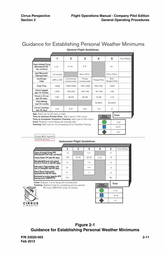
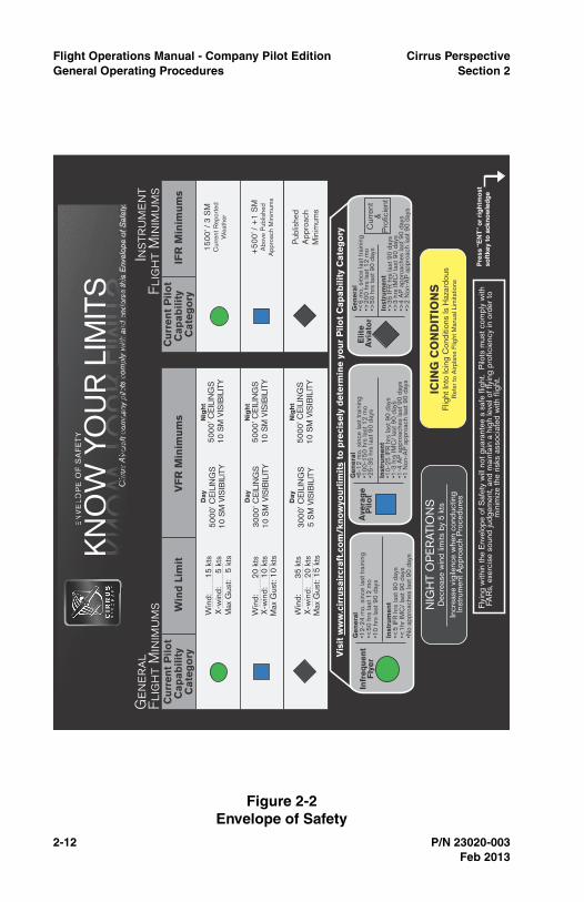
Pilot Weather MinimumsCirrus pilots will regularly assess their recent flight experience,training, and pilot certification to develop personal minimums for wind,ceiling and visibility, and instrument approach minimums. Use Figures2.1 and 2.2 on the following pages to aid in this process.
Wind Limits
Cirrus pilots shall not takeoff or land when the wind speed andcrosswind component exceed the individual's capabilities based uponflight experience and limits described in the Envelope of Safety, Figure2.2, considering the pilot’s risk category, Figure 2.1.
Flight Operations shall cease when the following conditions arepresent. Pilots should assess these conditions by ensuring forecastconditions are acceptable prior to flight.
• 35Kts total sustained wind component,
• 20Kts crosswind component,
• 10Kts tailwind component,
• Limits assigned due to personal capabilities,
• When taking off or landing on ice-covered runways (brakingaction reported poor), the crosswind component shall notexceed 10kts,
• If the wind exceeds 25kts or the Gust factor exceeds 10ktstakeoff and landing training shall not be conducted.
Unless the pilot is an authorized flight instructor, pilots providingdemonstration flights shall be the sole manipulator of the flight controlsduring landing if the sustained wind is in excess of 15 knots, or if thereis a gust factor in excess of 5 knots, or anytime it is necessary for safeflight. This policy does not preclude conducting other forms of trainingor demonstrations as long as the pilot performs the landing.
Requirements for Marginal VFR Flight
Marginal VFR (Ceiling 1000-3000 and visibility 3-5 miles) operationsmay be conducted if the pilot in command:
• Is instrument rated, current, equipped and is prepared to obtain an IFR clearance should conditions deteriorate,
Feb 2013

Cirrus Perspective Flight Operations Manual - Company Pilot EditionSection 2 General Operating Procedures
P/N 23020-003 2-9
• Has a valid mission requirement i.e.: required to avoid icing orthunderstorms that IFR flight would cause the flight to come incontact with,
• Does not use marginal VFR flight for cross country travel,
• Maintains contact with appropriate ATC facility if possible,
• The minimum ceiling and visibility required for traffic patternoperations is 1500 feet and 3 miles.
Requirements for Special VFR
The use of a Special VFR clearance is discouraged. However,operations under Special VFR are permitted if used to depart anairfield with weather below the VFR minima listed above provided theweather immediately outside the air traffic area is at least 1500 feetand 5 miles and the pilot meets the requirements for flight intoMarginal VFR conditions. Reference 14 CFR 91.157.
Example: The weather at Duluth is being reported as 900 feet and 5miles due to lake effect fog east of the airfield but the weather northand west of the field is clear. In this case, Special VFR may be used todepart the airfield. In all cases, pilots must use good judgment to avoidputting themselves in prolonged conditions of weather below 1000 feetand 3 miles.
Minimum Visibility for IFR Takeoff
The minimum visibility for takeoff in Cirrus owned or operated aircraftis ½ mile or RVR 1800’ unless the pilot is authorized for low visibilitytakeoffs. Authorization for low visibility takeoff allows the pilot to takeoffwith a minimum of RVR 600'. A pilot conducting a low visibility takeoffmust have a takeoff alternate within 50 miles of the departure airport.The current and forecasted weather conditions for the takeoff alternatemust not be lower than ceiling 600 feet and visibility 2SM.
Pilots may obtain low visibility authorization during recurrent training.Pilots in their IOE period are not eligible for low visibility authorization.
Envelope of Safety
The envelope of safety, Figure 2.2, describes weather minimums forrespective pilot risk categories. The risk category matrix must becompleted at each required training event. Pilot’s may not dispatch ifthe weather conditions including wind, ceiling, and visibility,considering day or night, is at or forecasted to exceed the weatherprescribed in the pilot’s category.
Feb 2013
2-10 P/N 23020-003
Flight Operations Manual - Company Pilot Edition Cirrus PerspectiveGeneral Operating Procedures Section 2
Pilots who lack currency requirements to achieve low weatherminimums but demonstrate mastery of the aircraft during an AnnualCheck or 6 Month Check may be placed into a higher weathercategory with the recommendation of the instructor and approval fromthe Director of Flight Operations. To be eligible for thisrecommendation, pilots must:
• Fly all instrument procedures during the check to the standardsset forth in the Airline Transport Pilot (ATP) Practical TestStandards
• Have more than 200 flight hours in a Cirrus with the sameavionics package
• The higher weather category is valid for 6 months or the nextrecurrent training event, whichever occurs first.
The instructor will mark the new weather minimums in the “InstructorRecommendation” section of the Annual Check paperwork and theDirector of Flight Operations will sign the document.
Feb 2013
Cirrus Perspective Flight Operations Manual - Company Pilot EditionSection 2 General Operating Procedures
P/N 23020-003 2-11
Figure 2-1Guidance for Establishing Personal Weather Minimums
1 2 3 4 5 Your Rating
Certificate Held
ATP or CFI Commercial w/instrument
Private w/instrument
Private Pilot
Pilot MishapLast 24 months
Incident Accident
Hours logged last 12 months
200 150-200 100-150 50-150 <50
Hours in Cirrus last 90 days
50 35-50 25-35 10-25 <10
Total Time 2000 1000-2000 750-1000 500-750 <500
Cirrus Landings last 30 days
10 6 -9 3-5 1-2 0
Total
�13
14-22
����
1 2 3 4 5 Your Ra�ng
>35 25--35 10-25 <5
Yes No
Total
�7
8-18
���
Guidance for Establishing Personal Weather Minimums General Flight Guidelines
Instrument Flight Guidelines
>
>
>
Recieved avionics specific IFRtraining from CSIP/CTC
Category Not Applicable for pilots in first 100 hours of aircraft operation.
>
5-10
>3
Instrument Approaches with use of Autopilot last 90 days
Hand-flown Instrument Approaches last 90 days
Simulated/Actual instrumenthours in Cirrus in last 90 days
>4
>2
1-3 <1
1-4
1
0
0
Pilot Category
Pilot Category
Years Actively Flying(Maintained FAA
req. currency)>10 6-10 2-5
Last Recurrent Training Event <6 months 6mo-12mo 12mo-24mo
Age: Add 2 pts for 65 years or olderTime to Achieve Private Pilot: Add 2 pts for 100+ hoursTime to Complete Transition Training: Add 2 pts for 30+ hoursCrew: Subtract 1 pt for flying with licensed pilot Training: Add 2 pts for not completing Cirrus Transition Training
Crew: Subtract 1 pt for flying with licensed pilotTraining: Subtract 2 pts for completing avionics specific IPC from CSIP/CTC in last 12 months.
Years Actively Flying IFR(Maintained FAA req. currency)
Hours flown IFR last 90 days
>5 <1
<2
1-5
Solo Student Pilot
Feb 2013
2-12 P/N 23020-003
Flight Operations Manual - Company Pilot Edition Cirrus PerspectiveGeneral Operating Procedures Section 2
Figure 2-2Envelope of Safety
IFR
Min
imu
ms
Pre
ss “
EN
T”
or
rig
htm
ost
so
ftke
y to
ack
no
wle
dg
e
EN
VE
LOP
EO
F S
AF
ET
Y:
KN
OW
YO
UR
LIM
ITS
Cu
rren
t P
ilo
tC
ap
ab
ilit
y C
ate
go
ryV
FR
Min
imu
ms
Win
d L
imit
Win
d:
2
0 k
ts X
-win
d:
10
kts
Max
Gus
t: 1
0 k
ts
30
00
’ CE
ILIN
GS
1
0 S
M V
ISIB
ILIT
Y
50
00
’ CE
ILIN
GS
1
0 S
M V
ISIB
ILIT
Y
Day
Day
Nig
ht
30
00
’ CE
ILIN
GS
5
SM
VIS
IBIL
ITY
Win
d:
3
5 k
ts X
-win
d:
20
kts
Max
Gus
t: 1
5 k
ts
5
00
0’ C
EIL
ING
S
10
SM
VIS
IBIL
ITY
Day
Nig
ht
Win
d:
1
5 k
ts X
-win
d:
5
kts
Max
Gus
t:
5 k
ts
50
00
’ CE
ILIN
GS
1
0 S
M V
ISIB
ILIT
Y
50
00
’ CE
ILIN
GS
1
0 S
M V
ISIB
ILIT
Y
Nig
ht
Cu
rren
t P
ilo
tC
ap
ab
ilit
y C
ate
go
ry
15
00
’ / 3
SM
Cur
rent
Rep
orte
dW
eath
er
+5
00
’ / +
1 S
MA
bov
e P
ublis
hed
Ap
pro
ach
Min
imum
s
Pub
lishe
dA
pp
roac
hM
inim
ums
Gen
eral
Fl
igh
t M
inim
ums
Inst
rum
ent
Flig
ht
Min
imum
s
ICIN
G C
ON
DIT
ION
SFl
ight
Into
Icin
g C
ond
ition
s Is
Haz
ard
ous
Ref
er t
o A
irpla
ne F
light
Man
ual L
imita
tions
Vis
it w
ww
.cir
rusa
ircr
aft
.co
m/k
no
wyo
url
imit
s to
pre
cise
ly d
ete
rmin
e y
ou
r P
ilo
t C
ap
ab
ilit
y C
ate
go
ry
Flyi
ng w
ithin
the
Env
elop
e of
Saf
ety
will
not
gua
rant
ee a
saf
e fli
ght
. P
ilots
mus
t co
mp
ly w
ithFA
Rs,
exe
rcis
e so
und
jud
gem
ent,
and
mai
ntai
n a
hig
h le
vel o
f fly
ing
pro
ficie
ncy
in o
rder
to
min
imiz
e th
e ris
ks a
ssoc
iate
d w
ith fl
ight
.
NIG
HT
OP
ER
ATI
ON
SD
ecre
ase
win
d li
mits
by
5 k
ts
Incr
ease
vig
ilenc
e w
hen
cond
uctin
gIn
stru
men
t A
pp
roac
h P
roce
dur
esDay
Cirr
us A
ircra
ft co
mpa
ny p
ilots
com
ply
with
and
end
orse
this
Env
elop
e of
Saf
ety.
s E
nvel
ope
of S
afet
y.sese
thi
pco
mp
dndoror
pm
py
pan
y p
eethth
ndndw
ots
crc
raf
Cirr
us
Infr
eq
uen
tF
lyer
Ave
rag
eP
ilo
tE
lite
A
viato
r
Gen
era
l•1
2-2
4 m
o. s
ince
last
tra
inin
g•<
50
hrs
last
12
mo
•10
hrs
last
90
day
s
Inst
rum
en
t•<
5 IF
R h
rs la
st 9
0 d
ays
•<1
hr IM
C/
last
90
day
s•N
o ap
pro
ache
s la
st 9
0 d
ays
Gen
era
l•6
-12
mo.
sin
ce la
st t
rain
ing
•10
0-1
50
hrs
last
12
mo
•25
-35
hrs
last
90
day
s
Inst
rum
en
t•1
0-2
5 IF
R h
rs la
st 9
0 d
ays
•1-3
hrs
IMC
/ la
st 9
0 d
ays
•1-4
AP
ap
pro
ache
s la
st 9
0 d
ays
•1 N
on-A
P a
pp
roac
h la
st 9
0 d
ays
Gen
era
l•<
6 m
o. s
ince
last
tra
inin
g•>
20
0 h
rs la
st 1
2 m
o •>
50
hrs
last
90
day
s
Inst
rum
en
t•>
35
IFR
hrs
last
90
day
s•>
3 h
rs IM
C/
last
90
day
s•>
4 A
P a
pp
roac
hes
last
90
day
s•>
2 N
on-A
P a
pp
roac
h la
st 9
0 d
ays
Cur
rent
&P
rofic
ient
Feb 2013

Cirrus Perspective Flight Operations Manual - Company Pilot EditionSection 2 General Operating Procedures
P/N 23020-003 2-13
Pilot Duty and Rest Period
Duty Time and Rest
To exercise flight privileges, the pilot shall not exceed a duty periodgreater than 14 hours including a maximum of 10 hours of PIC with amaximum of 8 hours as instruction. A 10 hour rest period is requiredbetween duty days when the pilot is required to exercise his or herflight privileges.
Flight Instructor Schedule Restrictions
In addition to the Duty Time and Rest requirements details above,Flight Instructors and Corporate Pilots must adhere to the followingrestrictions.
Flight Instructor Duty Day
• Instructor duty day must not exceed 14 hours, with no more than 10 hours of work related activities.
• Instructor duty day is defined by when the employee becomesactively engaged in work related activities until the employeeceases work related activities during which time the Instructorwill exercise his or her flight privileges.
• Work related activities include airline travel to or from the pointwhere a flight originates or concludes.
• Instructors must be given at least 12 hours of uninterrupted rest prior to a flight departing after 2100 local time. This applies onlywhen the late departure corresponds to the start of theInstructor's duty day.
Flight Time Restrictions
• A maximum of 8 hours flight instruction (hobbs) is permitted in a24 hour period.
Rest Period
• The Instructor must have 10 hours of rest with no workrelated activities between daily duty days.
Work Period
• The maximum working period is 8 consecutive days unlessapproved by the Director of Flight Operations.
• Work and travel periods that extend greater than 14 days arerare. Special time off and rest period considerations for work
Feb 2013
2-14 P/N 23020-003
Flight Operations Manual - Company Pilot Edition Cirrus PerspectiveGeneral Operating Procedures Section 2
periods that are greater than 14 consecutive days will be agreedupon between the Director of Flight Operations and theInstructor. Instructors must have at least one half day of rest forevery 8 consecutive days of work.
• Instructors must have a minimum of 3 consecutive days offfollowing any work period that exceeds 8 consecutive days.
Exceeding Duty Day, Work Period, or Flight Time Restrictions
Instructors may not originate a flight that will cause the Instructor toexceed duty day, flight time restrictions, or work period restrictionsunless:
• The instructor receives approval from the Director of FlightOperations to exceed duty days, work period, or flight timerestrictions.
• Such approval will be based on the Instructor's ability to safelycomplete the mission on a case by case basis.
Physiological Considerations
Intoxicants
The pilot shall not consume alcohol or other intoxicants within 8 hoursprior to flying and must always consider the lasting effects of alcoholthe following day. Reference 14 CFR 91.17
Blood Donations
A pilot should not operate an aircraft within 72 hours after a blooddonation or transfusion due to temporary lowering of oxygen carryingcapacity of blood following a blood donation or transfusion.
Scuba Diving
A pilot or passenger who intends to fly after scuba diving should allowthe body sufficient time to rid itself of excess nitrogen absorbed duringthe dive. The recommended wait times are as follows:
• Wait 12 hours - if flight will be below 8,000 feet pressure altitudeand dive did not require a controlled ascent.
• Wait 24 hours - if flight will be above 8,000 feet pressure altitudeor dive required a controlled ascent.
Supplemental Oxygen
Pilots are encouraged to utilize supplemental oxygen when operatingaircraft above 10,000 feet MSL during the day or above 5000 feet MSL
Feb 2013

Cirrus Perspective Flight Operations Manual - Company Pilot EditionSection 2 General Operating Procedures
P/N 23020-003 2-15
during night time per AIM recommendations. Reference 14 CFR91.211 for regulatory oxygen requirements.
Feb 2013
2-16 P/N 23020-003
Flight Operations Manual - Company Pilot Edition Cirrus PerspectiveGeneral Operating Procedures Section 2
Aircraft Maintenance and AirworthinessCirrus aircraft shall be maintained in accordance with the AirplaneMaintenance Manual, Pilot Operating Handbook, Federal AviationRegulations and the Demo Care Inspection and Maintenance Programmanual. Aircraft maintenance should be completed at a CirrusAuthorized Service Center or Factory Service Center.
Pilot Responsibilities
Pilots who operate Cirrus owned or operated aircraft must comply withthe following:
• Airworthiness
Pilots are responsible to determine if the aircraft meets applicableairworthiness regulations prior to each flight. If inoperativeequipment is found before or during flight, pilots must comply with14 CFR parts FAR 91.205, 91.213 and the next section of thisdocument to determine if the aircraft is airworthy and follow theguidance described therein.
For flying club aircraft, pilots must notify the flying club manager ofthe discrepancy and note the discrepancy in the fleetmanagement software to prevent future dispatch of the aircraftand to notify the Factory Service Center.
• Flight Times
Pilots are responsible for recording flight times in the Cirrus fleetmanagement system on a per flight basis within 3 business daysof completing the flight.
• Scheduled Maintenance
Pilots are responsible to ensure all scheduled maintenance items,described in the Demo Care Leaseback program, if applicable,and applicable regulations, are completed per the specifiedinterval. Demo Care inspections must be completed at anAuthorized Cirrus Service Center. Pilots are responsible to ensurethe log entries completed by the ASC are correct.
• Data Base Updates
Pilots are responsible for ensuring the currency of avionic’s databases and or paper or electronic charts, as required. Pilot’s whoare assigned aircraft will be provided with database managementtraining and associated accounts.
Feb 2013

Cirrus Perspective Flight Operations Manual - Company Pilot EditionSection 2 General Operating Procedures
P/N 23020-003 2-17
• General Aircraft Care
Aircraft will be maintained and detailed for cleanliness, proper tireinflation, etc. Cosmetic issues can be addressed at CirrusAuthorized Service Centers. All pilots will read & comply withsection 8 of POH (Handling, Service, & Maintenance)
• Unscheduled Maintenance
Pilots are responsible to ensure all unscheduled maintenanceitems are remedied in a timely fashion by a Cirrus AuthorizedService Center. Maintenance for AOG aircraft may be performedat a non Authorized Service Center. Pilots must coordinate anyunscheduled maintenance that is performed at a non-ASC repairstation that with the Cirrus Field Service department.
Inoperative Equipment or Instruments Checklist
Follow the guidance in this checklist when an inoperative equipment orinstrument failure has been identified either in flight or on the ground.
In flight equipment or instrument malfunctions
1. Follow the guidance in the appropriate AFM checklist
2. Land as soon as practical or possible as recommended by theAFM considering all factors involved.
On ground equipment malfunctions
1. Determine if the inoperative equipment or instrument are requiredper the following:
a. Indicated as required on the Kinds of Operations EquipmentList, found in Section 2 of the AFM, for the operation beingconducted,
b. Required by 14 CFR 91.205,
c. Required to be operational by an airworthiness directive forthe operation being conducted.
d. Required for safe flight.
If the inoperative equipment or instruments are not requiredper 1a, 1b, 1c, or 1d:
(1) Disable and placard the inoperative equipment prior toflight.
(2) Make arrangements to repair the inoperative equipment orinstruments at the earliest convenience.
Feb 2013
2-18 P/N 23020-003
Flight Operations Manual - Company Pilot Edition Cirrus PerspectiveGeneral Operating Procedures Section 2
If the inoperative equipment or instruments are required per1a, 1b, 1c, or 1d:
(1) Ground the aircraft,
(2) If an ASC is located on the airport, schedule maintenanceaccordingly, or
(3) If an ASC in not located on the airport, contact the CirrusHelp Desk to assist in coordinating maintenance.
Grounding of Aircraft
A Cirrus pilot or mechanic has the authority to ground an aircraftanytime it is determined to not be airworthy. Inform other pilots whomay fly the aircraft that the aircraft is unairworthy.
Feb 2013
Cirrus Perspective Flight Operations Manual - Company Pilot EditionSection 2 General Operating Procedures
P/N 23020-003 2-19
Flight Planning
Aircraft and Pilot Dispatch, Duluth and Grand ForksOperations
Anyone requesting a Cirrus corporate aircraft and/or pilot must receiveapproval from their area vice president. The Vice President's assistantwill complete an aircraft request form on the Cirrus Fleet Managementsystem. The aircraft and pilot will be dispatched based on the followingcriteria:
• Authorized Approval,
• Aircraft Availability,
• Pilot Availability,
• Dispatcher Approval,
• Weather.
Flight Plans
Pilots flying Cirrus owned or operated aircraft must file and open anIFR or VFR flight plan or obtain flight following for all flights greaterthan 100NM from the departure airport. Flight following may only beused when radar services are known to be available. If radar is notavailable or if flight following is discontinued in flight, the pilot must fileand open an IFR or VFR flight plan. Local area flights, such asdemonstration flights or flight training flights, that remain within 100NMfrom the departure airport do not require a flight plan. Pilots areencouraged to receive flight following services when operating VFR ona VFR flight plan or local flight.
The pilot should complete the following flight planning responsibilities:
• Determine the best route and altitude considering: winds aloft,freezing levels, cloud bases and tops, turbulence, terrain,airspace and TFRs,
• Determine an alternate airport,
• Calculate fuel requirements,
• Verify aircraft is within weight and balance limitations,
• Verify adequate climb performance for departure procedures,
• Calculate takeoff and landing distances. Verify runway lengthsfor intended airports,
Feb 2013

2-20 P/N 23020-003
Flight Operations Manual - Company Pilot Edition Cirrus PerspectiveGeneral Operating Procedures Section 2
• File flight plan.
IFR Alternate Airport Weather Requirements
If from 1 hour before to 1 hour after the estimated time of arrival at thedestination airport, the weather is forecast to be at least 2,000 footceilings and 3 mile visibilities, no alternate is required, though it isimportant to be familiar with the area in case a diversion is required. Ifforecasted weather conditions are less than 2,000 feet and 3 miles, analternate must be filed.
A pilot may only include an alternate airport in an IFR flight plan whenappropriate weather reports or forecasts, or a combination of them,indicate that, at the estimated time of arrival at the alternate airport,the ceiling and visibility at that airport will be at or above the followingweather minima:
• For a precision approach procedure: Ceiling 600 feet andvisibility 2 statute miles.
• For a Non-precision approach procedure: Ceiling 800 feet andvisibility 2 statute miles.
If an instrument approach procedure has not been published for theintended destination, the ceiling and visibility minima are thoseallowing descent from the MEA, approach and landing under basicVFR conditions and an alternate airport must be filed.
Fuel Requirements
No person may operate an aircraft in IFR conditions unless there isenough fuel (considering weather reports, forecasts, and weatherconditions) to:
• Complete the flight to the first airport of intended landing,
• Fly from that airport to the alternate airport,
• Fly after that for 45 minutes at normal cruising speed.
No person may begin a flight in an aircraft under VFR conditionsunless (considering wind and forecast weather conditions) there isenough fuel to fly to the first point of intended landing (assumingnormal cruising speed and fuel burn) and at least an additional 45minutes beyond that point in either day or night conditions.
Minimum Runway Length
The minimum runway length for any Cirrus aircraft is 2,500 feet ortwice the expected takeoff and/or landing distance, whichever is
Feb 2013
Cirrus Perspective Flight Operations Manual - Company Pilot EditionSection 2 General Operating Procedures
P/N 23020-003 2-21
greater. Exceptions to the minimum runway length must be authorizedby the Director of Flight Operations. Any planned off-airport landingrequires written authorization from the Director of Flight Operationsand applicable authorities.
Oxygen Equipment
Prior to flight, pilots should thoroughly understand and briefpassengers on how to use oxygen equipment and on signs of hypoxia.
Pulse Oximeter
Pilots are encouraged to use a pulse oximeter to monitor oxygensaturation of the blood. Pilots should adjust the flow rate of oxygen tomaintain a minimum of 90% saturation. If saturation cannot bemaintained above 90%, pilots should descend appropriately.
Weather Planning
A critical factor in a successful flight is the pilot's evaluation of weatherconditions. Many weather related accidents are avoidable and couldhave been prevented during pre-flight if the pilot thoroughly evaluatedthe weather conditions. The following weather resources will be usefulfor evaluating the weather:
Flight Service Station: .................................................. 800-WX-BRIEF
Aviation Weather Center ...............................www.aviationweather.gov
FlightPlan.com............................................................. www.fltplan.com
ForeFlight ................................................................ www.foreflight.com
National Weather Service....................................... www.nws.noaa.gov
The go/no-go decisions and the route to the intended destinationdepend greatly on the weather at the departure airport, along theroute, and at the destination. The pilot's ability to interpret andunderstand aviation weather is critical to the safety of flight. Follow thesteps below when assessing the weather for every flight.
Overview
The first step to understanding the weather conditions along theintended route is to assess the big picture. The pilot should becomefamiliar with pressure systems, frontal systems, precipitation, areas ofmarginal VFR and IFR conditions, and areas of icing and turbulence.Available weather products include:
• Surface analysis chart,
Feb 2013
2-22 P/N 23020-003
Flight Operations Manual - Company Pilot Edition Cirrus PerspectiveGeneral Operating Procedures Section 2
• Weather radar,
• Satellite imagery.
Hazards to Flight
The second step is to identify any potential hazards for the intendedflight. The pilot should become familiar with areas of marginal VFRand IFR conditions, convective activity, and areas of icing andturbulence. Available weather products include:
• Weather depiction chart,
• AIRMETs, SIGMETs and Convective SIGMETs,
• Weather radar,
• Pilot reports,
• Area forecast,
• Current and forecasted icing potential.
Current Observations
The third step is to become familiar with the current observationsalong the intended flight. Current weather observations within 50 milesof the departure, intended route and destination airport should beanalyzed. Available weather products include:
• METARs,
• Pilot reports.
Forecasted Weather
The fourth step is to understand what the weather is expected to doduring your flight. Evaluate the weather +/- 2 hours from yourestimated time of arrival at the destination and planned alternate.Available weather products include:
• TAFs,
• Area forecast,
• Prognostic charts,
• Winds and temperature aloft,
• AIRMETs, SIGMETs and Convective SIGMETs.
NOTAMS
The fifth step is to become aware of any NOTAMs that may affect theflight. Pay close attention to any TFRs that may interfere with yourroute.
Feb 2013
Cirrus Perspective Flight Operations Manual - Company Pilot EditionSection 2 General Operating Procedures
P/N 23020-003 2-23
Thunderstorm Flying
Never regard a thunderstorm lightly, even when radar observationsreport that echoes are of light intensity. Avoiding thunderstorms is thebest policy. The following are some Do’s and Don'ts of thunderstormavoidance:
• Don't land or takeoff in the face of an approaching thunderstorm.A sudden gust front or low level turbulence could cause loss ofcontrol.
• Don't attempt to fly under a thunderstorm even if you can seethrough to the other side. Turbulence and wind shear under thestorm could be disastrous.
• Don't trust the visual appearance to be a reliable indicator of theturbulence inside a thunderstorm.
• Do avoid by at least 20 miles any thunderstorm identified assevere or giving an intense radar echo. This is especially trueunder the anvil of a large cumulonimbus cloud.
• Do circumnavigate the entire area if the area has 6/10thunderstorm coverage.
• Do remember that vivid and frequent lightning indicates theexistence of a strong thunderstorm.
Regard as extremely hazardous any thunderstorm with tops35,000 feet or higher, whether the top is visually sighted ordetermined by radar.
Temperature Minimums
Flight training operations shall not be conducted when the outside airtemperature at the surface is -20 Fahrenheit or below. The aircraftshould be preheated if exposed to ground temperatures below 20Fahrenheit for more than two hours. Do not operate the engine atspeeds above 1700 RPM unless oil temperature is 100 Fahrenheit orhigher and oil pressure is within specified limits of 30-60 PSI. When oiltemperature has reached 100 Fahrenheit and oil pressure does notexceed 60 PSI at 2500 RPM, the engine has been warmed sufficientlyto accept full rated power.
Operations in Icing Conditions
• Caution •
Flight into icing conditions is hazardous. Refer to the airplaneflight manual for limitations.
Feb 2013
2-24 P/N 23020-003
Flight Operations Manual - Company Pilot Edition Cirrus PerspectiveGeneral Operating Procedures Section 2
A pilot is prohibited from taking off in an aircraft that has frost, snow,slush, or ice adhering to any external surface.
Icing can be expected when flying in visible moisture, such as rain,snow, or clouds, and the temperature of the aircraft is below freezing.If icing is detected, a pilot should turn on all available anti-icingequipment and do one of two things to exit the icing condition: get outof the area of visible moisture, or go to an altitude where thetemperature is above freezing. The warmer altitude may not always bea lower altitude. Proper pre-flight action includes obtaining informationon the freezing levels. Report icing to ATC and request new routing ornew altitude if icing is encountered.
Cirrus aircraft that are certified for Flight Into Known Icing (FIKI)conditions must operate within criteria defined by FAR Part 25,Appendix C. These conditions do not include, nor were testsconducted in all icing conditions that may be encountered such asfreezing rain, freezing drizzle, mixed conditions, or conditions definedas severe. Flight in these conditions must be avoided. Some icingconditions not defined in FAR Part 25 have the potential of producinghazardous ice accumulations, which exceed the capabilities of theairplane’s anti-ice system, and/or create unacceptable airplaneperformance including loss of control. Pilots who encounter icingconditions that are outside the FAR defined conditions should divertthe flight promptly. Inadvertent operation in these conditions may bedetected by unusually extensive ice accumulated on the airframe inareas not normally observed to collect ice.
If the airplane encounters conditions that are determined to containfreezing rain or freezing drizzle, immediately exit the freezing rain orfreezing drizzle conditions by changing altitude, turning back, or evencontinuing on the same course if clear air is known to be immediatelyahead.
Feb 2013
Cirrus Perspective Flight Operations Manual - Company Pilot EditionSection 2 General Operating Procedures
P/N 23020-003 2-25
Flight Considerations
Turns after Takeoff
The recommended turn altitude after takeoff is a minimum of 400 feetAGL, unless obstacle departure procedures or ATC instructions dictateotherwise. When cleared to fly runway heading, pilots should maintainthe heading that corresponds with the extended center line of thedeparture runway until otherwise directed by ATC. Drift correctionshould not be applied: i.e., Runway 04, with an actual magneticheading of the runway center line being 044 degrees, fly 044 degrees.
Noise Abatement
When operating out of noise sensitive airports pilots are encouragedto follow local noise abatement procedures and consider an RPMreduction from 2700 RPM to 2500 RPM during the climb if necessaryand safe. A power reduction in an SR22T has little effect on outsidenoise levels and is not necessary for noise abatement.
Weather Status
Pilots should monitor the weather along the route and destinationairport for deteriorating conditions using onboard weather resourcesand ground based weather resources. En route Flight AdvisoryService (EFAS), Flight Watch, is generally available on 122.0anywhere in the contiguous United States. A diversion may benecessary if the weather deteriorates beyond the pilot's qualificationsor capabilities.
Aircraft Systems Status
Pilots should monitor the flight, engine and system parametersthroughout the flight. Verify adequate fuel remains to reach theintended destination and switch fuel tanks as required to maintainwithin maximum fuel imbalance requirements.
Pilot Status
Pilots should monitor fatigue and stress levels during the flight. Adiversion may be necessary if the pilot has any reason to believe theflight can not be completed safely. Manage cockpit workload accordingthe procedures described in Section 3 of this manual. Pilots flyingabove 10,000 MSL should monitor oxygen saturation levels with a
Feb 2013
2-26 P/N 23020-003
Flight Operations Manual - Company Pilot Edition Cirrus PerspectiveGeneral Operating Procedures Section 2
pulse oxymeter frequently. Adjust oxygen flow rates or altitude tomaintain oxygen saturation levels above 90%
Aircraft Parking
The pilot in command of the aircraft is responsible for parking andsecuring the aircraft. The aircraft should be parked on a ramp or in ahangar. If the aircraft is parked outside, it should be secured withdoors locked (if applicable), chocked, and tied down if possible.
Pilots are discouraged from storing keys in the tail cone or engine cowlin order to prevent aircraft damage due to FOD.
Duluth Ramp Operations
• All aircraft must be parked with chocks under each main gearand the parking brake set,
• The parking first row of “T”s on the customer service ramp arereserved for customers or VIP guests only. Move corporateaircraft soon after dropping VIP guests to make room forcustomer parking,
• Move the aircraft from the customer service ramp to the mid fieldramp for pre taxi tasks as soon as practical after engine start,
• Minimize engine RPM on the customer service ramp,
• Do not leave chocks on the customer service ramp,
• Do not direct prop wash towards an open hanger,
• Coordinate hanger usage with the Aircraft Delivery Pilot.
Post Flight Inspection
Pilots are encouraged to conduct an abbreviated inspection after eachflight in order to identify maintenance issues that may have occurredduring flight. A post flight inspection may allow the pilot to identify andresolve any AOG maintenance issues and reduce aircraft downtime.Pilots should pay attention to the following items during a post flightinspection:
1. Main landing gear ............................................................... Inspect
Inspect the brake temperature sticker and general tire condition.Verify there are no brake fluid leaks.
2. Leading edge surfaces........................................................ Inspect
Inspect for signs of impact or damage from a possible bird strike.
3. Upper and lower fuselage ................................................... Inspect
Feb 2013
Cirrus Perspective Flight Operations Manual - Company Pilot EditionSection 2 General Operating Procedures
P/N 23020-003 2-27
Inspect for signs of excessive oil leak, and condition of externalantennas.
Feb 2013
2-28 P/N 23020-003
Flight Operations Manual - Company Pilot Edition Cirrus PerspectiveGeneral Operating Procedures Section 2
Flight Safety
Operating LimitationsIn addition to the operating limitations specific to each aircraft type, thefollowing actions are not permitted:
• Parachuting activities,
• Hand propped engine starts,
• Flight below 500' AGL except for takeoff and landing,
• Any activity for hire, lease, rent, profit, or reward outside thescope of Cirrus business,
• Flight over water beyond the safe gliding distance of land is notrecommended.
• Note •
Pilots should ensure that adequate survival gear is readilyaccessible if flight over water beyond the safe gliding distanceto land is required.
Sterile Cabin
During sterile cabin operations all distractions such as music, non-flight related activities, and unnecessary communication withpassengers should be minimized. A sterile cabin should be observedduring departure, arrival, and abnormal/emergency operations.
Smoking
Smoking is prohibited inside or near aircraft, hangars, and ramp areas.It is the responsibility of the pilot to ensure that passengers complywith these restrictions.
Collision Avoidance
The pilot shall maintain vigilance for other aircraft and use allresources available to avoid any situation which could result in acollision. Pilots are encouraged to file an IFR flight plan or requesttraffic advisories or flight following when operating in a radarenvironment.
Passenger Flight Briefing
Feb 2013
Cirrus Perspective Flight Operations Manual - Company Pilot EditionSection 2 General Operating Procedures
P/N 23020-003 2-29
The pilot shall provide a safety briefing, referencing the PassengerBriefing Card, to all passengers prior to each flight. The briefing shallprovide instructions for the following:
• CAPS procedures in the event of a pilot incapacitation,
• Seat belts,
• Exits,
• Safety equipment on the aircraft,
• Sterile cabin procedures.
Feb 2013
2-30 P/N 23020-003
Flight Operations Manual - Company Pilot Edition Cirrus PerspectiveGeneral Operating Procedures Section 2
Flying Club ProceduresThe procedures described in this section apply to Cirrus flying cluboperations only. Flying club pilots must adhere to these procedures aswell as the applicable sections of this document considering the flightoperation being conducted.
Membership Eligibility
The following individuals are eligible for membership in the Cirrusflying club:
• Direct employees of Cirrus Aircraft,
• Immediate family members of direct employees of CirrusAircraft.
Flying club dues for all club members will be deducted directly fromthe direct employee’s payroll.
New members must go through the flying club orientation prior toflying any club aircraft. Orientation will review all of the flying club'spolicy and procedures. A copy of the flying club orientation checklistcan be obtained from the flying club president or flight standards andoperations. A copy of the orientation checklist form must bemaintained in the individual's records folder.
Scheduling and Dispatch Procedures
Aircraft Reservations
Reservations for aircraft are be made through the flying club fleetmanagement system. Pilots may make a standby reservation’s foraircraft that have been previously reserved in order to utilize theaircraft if the primary reservation gets cancelled.
Pilots may only reserve and fly aircraft for which they are qualified perthe pilot’s authorization form during non instructional flights.
Instructor Reservations
Pilots must coordinate aircraft reservations with their instructor forinstructional flights. Pilots may reserve and fly any aircraft in whichtheir instructor is qualified to fly per the instructor’s authorization form.
Aircraft Dispatch
Aircraft must be dispatched prior to commencing the flight. The flyingclub’s fleet management system allows pilots to dispatch aircraft
Feb 2013
Cirrus Perspective Flight Operations Manual - Company Pilot EditionSection 2 General Operating Procedures
P/N 23020-003 2-31
provided their proficiency, currency, and aircraft maintenance are allfound to be satisfactory.
Pilots must dispatch within 15 minutes of the start of their scheduledtime slot. If the aircraft is not dispatched after 15 minutes, thereservation may be canceled and used by the next person.
Pilots who wish to dispatch after normal working hours may do so butshould take into consideration access to the building, hangers, etc.The flying club’s fleet management system will be used to dispatch theaircraft, but if flight instructor endorsements or approval is required forthe flight, pilots should make alternate plans to ensure all dispatchcriteria are met. Student pilots must discuss flight objectives with theirinstructor and have the appropriate authorizations before flying solo.During student pilot solo flights the individual’s flight instructor must beon the premises to dispatch their student.
In addition to the pre flight requirements detailed 14 CFR 91.103,pilots must complete the following tasks prior to dispatching in a clubaircraft:
• Schedule and dispatch the flight through the flying club fleetmanagement system,
• Complete a dispatch form for all flights,
• Verify and record aircraft times before engine start.
Pilots who reserve the aircraft for one or more overnights mustcompete these additional tasks:
• Have an authorized flying club instructor review the extendedforecast for the reservation period and sign the dispatch form orprovide written authorization for the flight.
• Note •
By authorizing the flight, the flight instructor is acknowledgingthat the forecasted weather appears to be acceptable for thepilot’s return leg. Ultimately, it is the pilot in commandsresponsibility to ensure safety of flight for all flight missions.Pilot’s may not re-dispatch for the return leg if the weather isbelow their authorization.
• A dispatch form must be completed for the return leg and for anyflights conducted during the overnight reservation prior toconducting the respective flight(s).
Fuel Procedures Outside of Base Operations
Feb 2013
2-32 P/N 23020-003
Flight Operations Manual - Company Pilot Edition Cirrus PerspectiveGeneral Operating Procedures Section 2
Pilots who purchase fuel outside of KDLH must pay out of pocket.Pilots will be reimbursed for the fuel purchased outside of KDLH at theCirrus bulk rate, which will be updated monthly. Pilots are responsiblefor the price difference between the Cirrus bulk rate and the actual fuelprice paid.
Mountainous Areas
Flying club members may not fly into or over areas defined asmountainous terrain by the Airman’s Information Manual unless thatpilot or instructor is authorized for flight into mountainous area, asnoted on the member’s Authorization form.
No Show or Cancellation Policy
Pilots who wish to cancel a mission may do so 24 hours in advance.When pilots cancel, they must notify any listed alternate for the aircraftvia telephone. Contact information is listed on the Sky Scheduler website. Cancellations within 24 hours prior to the flight may result in aminimum of one hour of flight time being charged to the individual if theindividuals fail to properly notify any listed alternate reservation.
Flight Training Requirements
Stage Checks
Stage checks are used as measuring points at various timesthroughout the training process.
For individuals pursuing a private pilot certificate, pilots must completea stage check with an instructor from the Flight Standards andOperations Department prior to:
• First solo,
• First solo cross country, and
• First attempt of the practical test.
For pilots training for an instrument rating, pilots must complete astage check at the completion of:
• Basic attitude instrument flying,
• The approach phase of training, and
• First attempt of the practical test.
For pilots training for a commercial pilot certificate, pilots mustcomplete a stage check prior to:
• First attempt of the practical test.
Feb 2013
Cirrus Perspective Flight Operations Manual - Company Pilot EditionSection 2 General Operating Procedures
P/N 23020-003 2-33
Pre Solo Written Test
Prior to solo, instructors must administer and correct to 100% a pre-solo written examination. This document can be obtained from theFlight Standards and Operations Department. The original writtenexam must be kept in the student's record folder.
Student Pilot First Solo Procedures
After successful completion of the pre-solo written and pre-solo stagecheck, the student's instructor will have the final decision as to whenthe student may solo. The day of the solo, the instructor should fly withthe student and have him or her demonstrate 3 consistent andsuccessful landings prior to endorsing the student to fly solo.
The instructor should also ensure the student has all requireddocumentation prior to soloing, including:
• Student pilot certificate,
• Medical,
• Photo ID, and
• Logbook with appropriate endorsements.
The student should complete 3 full stop landings and full taxi backs ontheir first solo. Touch and goes are not permitted on the first solo.
Weather conditions for the first solo must be:
• Visibility greater than 6 SM,
• Ceilings overcast at 3,000 or better,
• Winds less than 10 knots, with a maximum cross windcomponent of 5 knots.
Student Pilot Solo Weather Minimums
Student pilots may not dispatch if the actual or forecasted weatherexceeds the weather limitations described in the instructorendorsement. Student pilot weather limitations must always equal orbe more restrictive then the weather minimums described in theEnvelope of Safety based upon the student’s demonstratedproficiency.
Student Pilot Limitations
In addition to the student pilot limitations described in 14 CFR 91.61.89, student pilot may not conduct the following activities:
• Flights after sunset and before sunrise,
Feb 2013
2-34 P/N 23020-003
Flight Operations Manual - Company Pilot Edition Cirrus PerspectiveGeneral Operating Procedures Section 2
• Flights that are in conjunction with any Cirrus or personalbusiness.
Flying Club Instructors
To be eligible to provide instruction in Cirrus flying club aircraft, eachflight instructor must:
• Hold a current CFI for private or commercial pilot training,
• Hold a CFII for instrument training,
• Complete the CSIP course for initial training,
• Complete recurrent training per the requirements detailedherein,
• Be a current member of the club.
Feb 2013
Cirrus Perspective Flight Operations Manual - Company Pilot EditionSection 2 General Operating Procedures
P/N 23020-003 2-35
International Border Operations
Pre-Flight
• Appropriate charts and flight supplements
Personal Documentation
• Pilot certificate with “English Proficient” endorsement,
• Medical certificate,
• FCC Restricted Radiotelephone Operator Permit,
• Proof of citizenship,
• Passport,
• Resident alien ID Card (if required),
• Other Visa documentation as required,
• Notarized letter authorizing children to fly (if accompanied byonly one parent).
Aircraft Documentation
• Airworthiness certificate,
• Registration certificate (not temporary registration certificate),
• Operating limitations (approved aircraft flight manual),
• Weight and balance information,
• FCC Aircraft Radio Station License,
• Proof of liability insurance for the specific country,
• U.S. Customs Annual User Fee Decal (Form 339A),
• FAA Form 337 (U.S. aircraft only) or STC documentation if fueltanks have been added in baggage or passengercompartments,
• Experimental Aircraft - Standardized Validation (for operations inCanada) or Special Flight Authorization (for operations in U.S.).
Crossing the United States and Canadian Border
Departure
• Provide passenger manifest to U.S. Customs using ElectronicAdvance Passenger Information System (eAPIS) at least 1 hourprior to departing from or arriving in the United States,
Feb 2013

2-36 P/N 23020-003
Flight Operations Manual - Company Pilot Edition Cirrus PerspectiveGeneral Operating Procedures Section 2
• https://eapis.cbp.dhs.gov,
• Give advance notification to Customs,
• U.S. to Canada - contact CANPASS no less than 2 hoursbefore and no more than 48 hours before arrival at 888-CAN-PASS (226-7277),
• Canada to U.S. - telephone Customs office at airport ofentry no less than 1 hour and no more then 23 hours beforearrival; enter ADCUS in Remarks block of flight plan form,
• File and activate a VFR or IFR flight plan,
• Advise Customs if any change in ETA at airport of entry via ATC/FSS while in flight, and get the badge number and name of theCustoms official that ATC/FSS is communicating with.
Arrival
• Make first landing at an airport of entry (AOE),
• Taxi to the Customs area on ramp,
• In the U.S. - Arrive at the destination at or within 15 minutesof your planned ETA. Wait in the aircraft for the Customsofficial to motion you out of aircraft,
• In Canada - if not met, find a telephone and call 888-CAN-PASS, follow directions from Customs official, obtain arrivalreport number,
• If inspected, present documentation as required, fill out anydeclaration forms and pay appropriate duties and taxes,
• Close your flight plan.
Feb 2013
Cirrus Perspective Flight Operations Manual - Company Pilot EditionSection 2 General Operating Procedures
P/N 23020-003 2-37
Incident and Accident Procedures (U.S. Only)Pilots shall immediately notify the nearest National TransportationSafety Board field office if an aircraft incident or accident occurs asdefined in NTSB Part 830. The proper law enforcement agency and/orsearch and rescue shall be notified if necessary. The pilot shouldcomplete the Aircraft Accident and Incident Report, found in thissection, after any incident or accident. The pilot should not discuss thecircumstances with anyone not involved with the investigation.
Emergency Landing
If a Cirrus aircraft makes an emergency landing at a site notdesignated as an airport, the pilot should not attempt to takeoff, butshould immediately contact the proper authorities.
Aircraft Incident and Accident Notification
An Aircraft Incident and Accident Report should be completed by thepilot any time a Cirrus aircraft sustains any damage or is involved in anincident or accident. The information may be useful in a futureinvestigation. The report form is found in this manual.
NTSB Field Offices
Eastern Region
Atlanta, GA ......................................................................404-562-1666
Miami, FL.........................................................................305-597-4610
Ashburn, VA ....................................................................571-223-3930
Central Region
Chicago, IL ......................................................................630-377-8177
Denver, CO......................................................................303-373-3500
Arlington, TX....................................................................817-652-7800
Western Region
Seattle, WA......................................................................206-870-2200
Gardena, CA ...................................................................310-380-5660
Alaska Region
Anchorage, AK ................................................................907-271-5001
Feb 2013
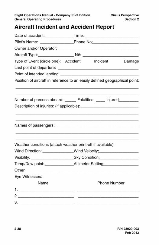
2-38 P/N 23020-003
Flight Operations Manual - Company Pilot Edition Cirrus PerspectiveGeneral Operating Procedures Section 2
Aircraft Incident and Accident ReportDate of accident:_____________Time: ________________________
Pilot's Name: _______________Phone No:_____________________
Owner and/or Operator: ____________________________________
Aircraft Type:________________ N#: _________________________
Type of Event (circle one): Accident Incident Damage
Last point of departure: ____________________________________
Point of intended landing: ___________________________________
Position of aircraft in reference to an easily defined geographical point:
_______________________________________________________
_______________________________________________________
Number of persons aboard: _____ Fatalities: ____ Injured:_________
Description of injuries: (if applicable):__________________________
_______________________________________________________
_______________________________________________________
Names of passengers: _____________________________________
_______________________________________________________
_______________________________________________________
Weather conditions (attach weather print-off if available):
Wind Direction: ______________Wind Velocity:__________________
Visibility: ___________________Sky Condition:__________________
Temp/Dew point:_____________Altimeter Setting:________________
Other___________________________________________________
Eye Witnesses:
Name Phone Number
1._________________________ ___________________________
2._________________________ ___________________________
3._________________________ ___________________________
Feb 2013

Cirrus Perspective Flight Operations Manual - Company Pilot EditionSection 2 General Operating Procedures
P/N 23020-003 2-39
Damage to Aircraft/Property (If yes, explain): ___________________
______________________________________________________
______________________________________________________
Description of any dangerous cargo:__________________________
______________________________________________________
______________________________________________________
Detailed explanation of incident, accident, or damage:____________
______________________________________________________
______________________________________________________
______________________________________________________
______________________________________________________
______________________________________________________
______________________________________________________
______________________________________________________
______________________________________________________
______________________________________________________
______________________________________________________
______________________________________________________
______________________________________________________
______________________________________________________
______________________________________________________
______________________________________________________
______________________________________________________
______________________________________________________
______________________________________________________
______________________________________________________
______________________________________________________
______________________________________________________
______________________________________________________
______________________________________________________
______________________________________________________
Feb 2013
2-40 P/N 23020-003
Flight Operations Manual - Company Pilot Edition Cirrus PerspectiveGeneral Operating Procedures Section 2
_______________________________________________________
_______________________________________________________
_______________________________________________________
_______________________________________________________
_______________________________________________________
_______________________________________________________
_______________________________________________________
_______________________________________________________
_______________________________________________________
_______________________________________________________
_______________________________________________________
_______________________________________________________
_______________________________________________________
_______________________________________________________
_______________________________________________________
_______________________________________________________
_______________________________________________________
_______________________________________________________
_______________________________________________________
_______________________________________________________
_______________________________________________________
_______________________________________________________
_______________________________________________________
_______________________________________________________
_______________________________________________________
_______________________________________________________
_______________________________________________________
_______________________________________________________
_______________________________________________________
Feb 2013
Cirrus Perspective Flight Operations Manual - Company Pilot EditionSection 3 Standard Operating Procedures
P/N 23020-003 3-1
Section 3Standard Operating Procedures
GeneralThe Standard Operating Procedures section describes therecommended procedures when operating a Cirrus aircraft duringvisual and instrument conditions. This information should serve as aframework for aircraft and avionics management. These standardoperating procedures were developed by and are used by professionalpilots and flight instructors at Cirrus Aircraft. The procedures outlinedare considered the best operating practices while flying Cirrus aircraft;however, these procedures may not be inclusive to all variablesencountered in the national airspace system. Cirrus pilots areencouraged to follow the procedures outlined in this manual, use theirbest judgment, and adapt these procedures when handling non-standard situations.
• Note •
Checklist procedures in the FOM have been designed toaccommodate all aircraft equipped with Cirrus Perspectiveavionics. In each checklist, items that are specific to onlycertain aircraft will be noted in each procedure. Unlessspecified, items will apply to all aircraft with Cirrus Perspectiveavionics.
Utilizing these standard operating procedures will enhance thesituational awareness of the pilot in both single pilot and crewsituations and allow for timely completion of tasks in the aircraft.Adhering to these procedures will help the pilot take full advantage ofthe aircraft's capabilities while maintaining a high level of safety.
• Note •
Procedures in this publication are derived from procedures inthe FAA Approved Airplane Flight Manual (AFM). CirrusAircraft has attempted to ensure that the data containedagrees with the data in the AFM. If there is any disagreement,the Airplane Flight Manual is the final authority.
Feb 2013

3-2 P/N 23020-003
Flight Operations Manual - Company Pilot Edition Cirrus PerspectiveStandard Operating Procedures Section 3
Single Pilot Resource ManagementSingle Pilot Resource Management (SRM) is the ability to manage allthe resources available to a pilot to ensure that the successfuloutcome of the flight is never in doubt.
The majority of Cirrus aircraft operations are conducted as single-pilot.The workload associated with flying the aircraft, configuring andmonitoring avionics, communicating with air traffic control, anddecision making requires pilots to efficiently manage all tasks whilemaintaining positive aircraft control at all times. The following SRMprocedures have been adapted from cockpit procedures common todual pilot transport category aircraft.
General aviation pilots have a great deal of latitude on how to manageand operate aircraft. To ensure the highest levels of safety, it is stronglyrecommended that these single pilot operating procedures beincorporated into the operation of the aircraft.
Priority of Tasks
The following is a list of priorities that apply to any situationencountered in flight. Pilots must adhere to these priorities duringevery flight.
1. Maintain Aircraft Control
The number one priority of the pilot is to maintain aircraft control.Pilots should maintain a high level of vigilance during periods ofhigh and low workload to ensure aircraft control is alwaysmaintained.
2. Navigation
Once aircraft control is assured, pilots should set and verify thatthe avionics are correctly configured for navigation. This taskincludes creating and modifying flight plans, selecting propernavigation sources and/or tuning navigation frequencies. Use ofthe autopilot may assist the pilot with accomplishing these tasks.Pilots should monitor flight parameters closely while programmingvarious avionics equipment.
3. Communication
Communication is an important task in the aircraft but followsaircraft control and navigation as a priority. This task includessetting assigned frequencies, controlling communication volumeand responding to ATC instructions. Communicate intentions and
Feb 2013
Cirrus Perspective Flight Operations Manual - Company Pilot EditionSection 3 Standard Operating Procedures
P/N 23020-003 3-3
relay instructions clearly to ATC/CTAF while maintaining aircraftcontrol.
• Note •
Using Standard Operating Procedures will aid the pilot intimely completion of required tasks and allow the pilot tomaintain high levels of situational awareness.
Using Standard Operating Procedures
The use of Standard Operating Procedures will allow for single-pilotoperations with higher levels of safety and efficiency. Followingstandard procedures during flight operations will develop habitpatterns through repetition that allow pilots to be most efficient whilecompleting tasks and configuring the aircraft for various phases offlight. Section 3 of this manual details and describes therecommended procedures for operating a Cirrus aircraft in a normalflight environment for both VFR and IFR operations.
Use of All Available Resources
The use of all available resources during flight in single-pilotoperations will allow pilots to make better and more timely decisions.Many resources are available to pilots such as: ATC, Flight Watch orFlight Service Stations, on-board weather displays, on-board chartdisplays, and even passengers.
Collision Avoidance
It is the responsibility of the pilot in command to see and avoid otheraircraft. Pilots should use care during all movement on the ground.Read back all hold short instructions and visually verify that runwaysare clear prior to crossing. Use of SafeTaxi and/or Charts will increasethe pilot’s situational awareness during movement on the ground.
While in visual conditions pilots should regularly scan outside theaircraft in sweeping ten degree increments. Pilots are encouraged touse resources on board the aircraft to identify possible threats beforethey become a hazard. Displaying traffic on the PFD inset map willcontinuously assist pilots to see and avoid other traffic. Remember,non-transponder-equipped aircraft will not be detected by on-boardtraffic systems.
Feb 2013

3-4 P/N 23020-003
Flight Operations Manual - Company Pilot Edition Cirrus PerspectiveStandard Operating Procedures Section 3
Terrain Avoidance
Pilots are at greatest risk for controlled flight into terrain (CFIT)accidents during high workload situations (departure and arrival), inunfamiliar terrain or airspace, and in restricted visual conditions (IMCor night). Chances of a loss of control or CFIT accident is greatlyincreased when VFR flight is continued into IMC conditions. Properpre-flight weather planning will reduce the likelihood of accidental flightinto IMC conditions. Adhere to these guidelines to reduce thelikelihood of a CFIT accident.
• Verify that departure, enroute and destination weatherconditions allow for safe completion of the flight,
• Become familiar with all terrain and obstacle hazards for theplanned route and plan the route and altitudes accordingly,
• Become familiar with any departure procedures and brief thedeparture procedures prior to takeoff,
• Exercise sterile cabin procedures during high workload periods,
• Reference TAWS information in mountainous terrain. Ensure thethe range is set to less than 100NM,
• Maintain situational awareness at all times using the toolsonboard the aircraft including: moving map displays, TAWS, andnavigation information,
• Proceed with caution and maintain high levels of vigilance whenoperating in unfamiliar terrain, especially during low or restrictedvisibility.
Feb 2013
Cirrus Perspective Flight Operations Manual - Company Pilot EditionSection 3 Standard Operating Procedures
P/N 23020-003 3-5
Checklist PhilosophyWhen used properly, checklists enhance the safety of flight byconfirming the aircraft is appropriately configured for the flightcondition. At the same time, checklists expedite the completion ofprocedures that are necessary to transition to subsequent phases offlight.
The electronic checklist in the MFD should be used anytime the MFDis running. Use of electronic checklists will help keep the cockpitorganized and functional. Use a paper checklist whenever the MFDelectronic checklists are not available.
Classification of Checklists
All checklist procedures can be assigned one of three classifications:
Normal: Procedures used during normal flight operations.Normal checklists can be found in the NormalProcedures section of the POH.
Abnormal: Procedures used in response to system failuresand malfunctions that, while not immediatelythreatening, may affect safety of flight if notaddressed. Abnormal checklists can be found inthe Abnormal Procedures section in the POH.
Emergency: Procedures used in response to system failuresand malfunctions that are an immediate threat tothe safety of flight. Emergencies require immediateaction by the flight crew to ensure a safe outcome.Emergency checklists can be found in theEmergency Procedures section of the POH.
Feb 2013
3-6 P/N 23020-003
Flight Operations Manual - Company Pilot Edition Cirrus PerspectiveStandard Operating Procedures Section 3
Checklist Completion for Normal Procedures
Normal procedure checklists can be completed as a flow pattern or ado-list. The appropriate method for checklist completion for eachnormal procedure is indicated in the procedures section for eachphase of flight.
Do-List: A do-list checklist is executed by reading thechecklist item and selecting the appropriatecondition of the item. Do-lists are used whenprocedure sequence and/or item condition iscritical to completion of the procedure and whenample time exists for completion of the checklist.
Flow Pattern: The term “flow pattern” refers to a logical paththrough the cockpit that the pilot will move alongduring the execution of the checklist. Flow patternsuse a “do and verify” approach to checklistcompletion. The items and their conditions arememorized and executed without immediatereference to the written checklist. Followingcompletion of the flow pattern, the checklist isreferenced as soon as time and workload permit toensure procedure completion.
When used properly, flow patterns allow timelyconfiguration of the aircraft for the appropriate flightcondition. Flow patterns are used when proceduresequence and aircraft condition are not critical andthere is an operational advantage to executing thechecklist items in a timely manner.
Feb 2013

Cirrus Perspective Flight Operations Manual - Company Pilot EditionSection 3 Standard Operating Procedures
P/N 23020-003 3-7
Pre-Flight InspectionThe pre-flight inspection should be completed as a flow pattern whenthe pilot is familiar with the aircraft pre-flight inspection checklist.Always refer to the aircraft checklist after the flow to verify that all itemshave been completed.
Documentation
The following documents must be in the aircraft for the flight:
• Certificate of Airworthiness,
• Registration,
• FAA Approved Airplane Flight Manual and Pilot’s OperatingHandbook, including weight and balance,
• Radio Station License for International Operations,
• Appropriate Avionics Publications.
Equipment
The following equipment should be carried in the aircraft whenappropriate:
• Survival kit (appropriate to the climate and conditions),
• Approved flotation devices for flights over water beyond glidingdistance to land,
• Supplemental oxygen system for high altitude operations,
• Chocks, tie downs, extra oil, tow bar, engine and airplanecovers.
Ground Icing
A visual inspection and tactile check of the entire aircraft is requiredbefore takeoff whenever conditions conducive to ground icing arepresent. Pilots are prohibited from taking off in an aircraft that hasfrost, snow, slush, or ice adhering to any external surface.
FIKI - Dispatch into known icing conditions is prohibited if porouspanels do not fully “wet-out”, or if there is a persistent annunciationof any anti-ice system crew alert system (CAS) message.
Feb 2013
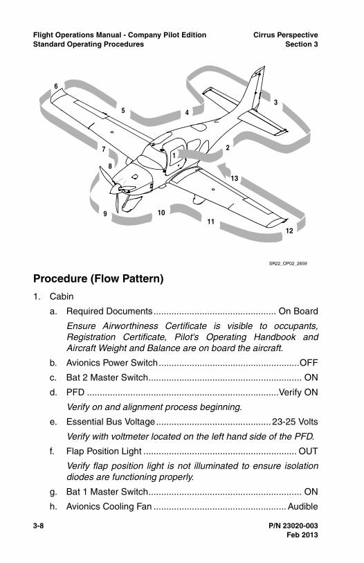
3-8 P/N 23020-003
Flight Operations Manual - Company Pilot Edition Cirrus PerspectiveStandard Operating Procedures Section 3
Procedure (Flow Pattern)
1. Cabin
a. Required Documents................................................ On Board
Ensure Airworthiness Certificate is visible to occupants,Registration Certificate, Pilot's Operating Handbook andAircraft Weight and Balance are on board the aircraft.
b. Avionics Power Switch.......................................................OFF
c. Bat 2 Master Switch............................................................ ON
d. PFD ...........................................................................Verify ON
Verify on and alignment process beginning.
e. Essential Bus Voltage............................................. 23-25 Volts
Verify with voltmeter located on the left hand side of the PFD.
f. Flap Position Light ............................................................ OUT
Verify flap position light is not illuminated to ensure isolationdiodes are functioning properly.
g. Bat 1 Master Switch............................................................ ON
h. Avionics Cooling Fan .................................................... Audible
SR22_OP02_2659
3
1
5
6
7
8
9 1011
12
13
4
2
Feb 2013
Cirrus Perspective Flight Operations Manual - Company Pilot EditionSection 3 Standard Operating Procedures
P/N 23020-003 3-9
Listen for cooling fan operation.
i. Oxygen Masks/Cannulas and Hoses .............Check Condition
j. Oxygen System ...................................................................ON
(1) Quantity........Verify adequate supply for flight with reserve
(2) Flow ................................... Check flowmeter on all masks
(3) Oxygen System...........................................................OFF
k. Avionics Master Switch (FIKI)..............................................ON
Avionics Master and audio panel must be turned on and flapsmust be 100% down in order to test stall warning on ground.
l. Flaps...................................................100%, Check Lights ON
Visually verify down and ensure light corresponds with flapsetting.
m. PITOT HEAT Switch ............................................................ON
FIKI - Limit ground operations of Pitot Heat to 45 seconds.Operations of Pitot Heat in excess of 45 seconds while on theground may cause excessive temperature on stall warningtransducer faceplate and surrounding wing skin.
n. Lights............................................................. Check Operation
Verify operation of required interior (overhead, instrument andpanel lights) and exterior (navigation, landing, anti-collision,and ice lights). Strobe lights are required for all flightoperations. Navigation lights are required for all nightoperations.
o. Stall Warning Faceplate (FIKI) .........................Perceptibly Hot
Stall warning faceplate should become hot when Pitot Heat ison. Use caution to avoid burns when checking systemoperation.
p. Stall Warning ......................................................................Test
Test stall warning system by applying suction to the stallwarning system inlet and noting the warning horn sounds.
FIKI - Verify Stall Warning System audio annunciationoperation by lifting stall warning vane with wooden tooth pickor tongue depressor. Stall warning vane should be very hot.Avionics Master and audio panel must be turned on and flapsmust be 100% down in order to test stall warning on ground.
Feb 2013

3-10 P/N 23020-003
Flight Operations Manual - Company Pilot Edition Cirrus PerspectiveStandard Operating Procedures Section 3
q. Pitot Heat..........................................................Perceptibly Hot
Verify the pitot tube is hot.
r. Fuel Quantity ..................................................................Check
Ensure fuel quantity is sufficient for planned flight andcorresponds to fuel amount in tanks and on MFD.
s. Fuel Selector ..............................................Select Fullest Tank
Switch fuel selector to the fullest tank. Maximum fuelimbalance: 7.5 (SR20), 10 gal SR22(T),(TN),(G5).
t. Alternate Static Source............................................. NORMAL
Visually verify alternate static source located near pilot's rightknee, above circuit breaker panel is in the NORMAL position.
u. Bat 1 and 2 Master Switches.............................................OFF
Ensure both battery switches are turned off.
v. Circuit Breakers .................................................................... IN
Ensure all circuit breakers are in and none are in re-settable(tripped) condition.
w. Fire Extinguisher...................................Charged and Available
Inspect extinguisher and ensure pin and safety wire are intact.There is no gauge to measure quantity.
x. Emergency Egress Hammer ......................................Available
Hammer should be stowed securely inside lid of the arm restbetween the front seats.
y. CAPS Handle ..................................................... Pin Removed
Remove safety pin and stow for remainder of flight. Be sure toreplace CAPS cover after pin removal as it is a requiredplacard. Consider delaying this checklist item until allpassengers are boarded and provide a passenger CAPSbriefing at that time.
2. Left Fuselage
a. Door Lock ......................................................................Unlock
Ensure the door lock is in the unlocked position to allowoutside entry into the aircraft in the event of an accident.
b. COM 1 Antenna.............................. Condition and Attachment
Feb 2013
Cirrus Perspective Flight Operations Manual - Company Pilot EditionSection 3 Standard Operating Procedures
P/N 23020-003 3-11
Visually check condition of antenna and surrounding area offuselage.
c. Wing/Fuselage Fairing....................................................Check
Visually inspect the wing root fairing for attachment alongupper and lower surfaces of wing root.
d. COM 2 Antenna...............................Condition and Attachment
Visually check condition of antenna and surrounding area offuselage.
e. Transponder Antenna ......................Condition and Attachment
The transponder antenna is located on the bottom side of theairplane, just aft of the baggage compartment bulkhead on theRH side of the aircraft.
f. Baggage Door ........................................... Closed and Secure
Physically check for locked and secured door and ensure keysare removed.
g. Static Button .............................................. Check for Blockage
Ensure removal of static covers if used and check for anyblockage within static port openings.
h. Parachute Cover...................................... Sealed and Secured
Visually inspect area on top rear of fuselage directly behindrear top window for any cracks.
3. Empennage
a. Tie Down Rope............................................................Remove
Visually verify tail tie down is removed and stowed.
b. Horizontal and Vertical Stabilizers.............................Condition
Inspect leading edges and top of vertical stabilizer for anyabnormalities. Ensure the clear tape covering inspection holeinside of elevator horn is intact.
c. Elevator and Tab............................... Condition and Movement
Check elevator for range of motion. Inspect tab on left side ofelevator for condition. Visually inspect counter weight insideelevator horn for security. Check all hinges, bolts, and cotterpins.
d. Rudder............................................... Freedom and Movement
Feb 2013
3-12 P/N 23020-003
Flight Operations Manual - Company Pilot Edition Cirrus PerspectiveStandard Operating Procedures Section 3
Inspect for full range of motion. Inspect all hinges, bolts, andcotter pins from the left side of the rudder. Visually inspectcounter weight inside top leading edge of rudder horn forsecurity.
e. Rudder Trim Tab ...................................Condition and Security
f. Attachment Hinges, Bolts and Cotter Pins ................... Secure
Verify all moveable control surfaces are secure and all boltsand cotter pins are in place.
4. Right Fuselage
a. Static Button ..............................................Check for Blockage
Ensure removal of static covers and check for any blockagewithin static port openings.
b. Wing/Fuselage Fairings ..................................................Check
Visually inspect the wing root fairing for attachment alongupper and lower surfaces of wing root.
c. Door Lock .................................................................. Unlocked
Ensure the door lock is in the unlocked position to allowoutside entry into the aircraft in the event of an accident.
5. Right Wing Trailing Edge
a. Flaps and Rub Strip (if installed) ..........Condition and Security
Inspect flap hinges, bolts and cotter pins for security and verifya small amount of movement when flaps are in an extendedposition. Visually inspect rub strip for abnormal chafing.
b. Aileron and Tab................................. Condition and Movement
Verify full deflection of right aileron and ensure oppositedeflection of left aileron. Inspect control assemblies locatednear the leading edge of outboard and inboard aileron.Inspect the security of the bolt located under the inboard edgeof the aileron.
c. Aileron Gap Seal .........................................................Security
Visually inspect the aileron gap seal for attachment along theentire surface.
d. Hinges, Actuation Arm, Bolts and Cotter Pins .............Security
Verify all moveable control surfaces are secure and all boltsand cotter pins are in place.
Feb 2013
Cirrus Perspective Flight Operations Manual - Company Pilot EditionSection 3 Standard Operating Procedures
P/N 23020-003 3-13
6. Right Wing Tip
a. Tip ..........................................................................Attachment
Ensure all screws are in place on upper and lower surfaces.Visually inspect for damage to leading edge, trailing edge, andwing tip.
b. Strobe, Nav Light and Lens ..................Condition and Security
Inspect for security of lights and lighting covers.
c. Fuel Vent (underside) ..........................................Unobstructed
Verify there are no obstructions to the fuel vent.
7. Right Wing Forward and Main Gear
a. Leading Edge and Stall Strips ...................................Condition
Inspect leading edge for any abnormalities. Ensure both stallstrips are secured.
b. Fuel Cap....................................... Check Quantity and Secure
Visually check fuel is at desired amount and the fuel cap issecured and locking tab is facing rearward. Lock fuel caps asdesired.
c. TKS Fluid Reservoir (FIKI) .................. Verify Desired Quantity
Check cap condition and security. Minimum dispatch level forflight into known ice is 5 gallons between the two tanks. Useonly approved fluid meeting DTD-406B standards.
d. Fuel Drains (2 underside)............................ Drain and Sample
Use a clear fuel strainer and sample fuel from the main tankand the collector tank. Visually check color for grade of fueland inspect for contaminants. Ensure fuel drains do not leakafter taking sample. Do not use the same sample cup used todrain the TKS system.
e. TKS Fluid Vent (underside wing) (FIKI) ...............Unobstructed
Verify there are no obstructions to the TKS fluid vent.
f. Wheel Fairings...................... Security, Accumulation of Debris
Physically ensure security of wheel pants. Check for andremove any debris in wheel pants (ice or slush may haveformed during taxi).
g. Tire .............................................Condition, Inflation and Wear
Feb 2013
3-14 P/N 23020-003
Flight Operations Manual - Company Pilot Edition Cirrus PerspectiveStandard Operating Procedures Section 3
Inspect tire for excessive wear to include flat spots, bald spotsor visible tire chords. Ensure adequate tire inflation. Movingthe aircraft may be necessary to visually inspect the entire tirefor overall condition if excessive wear is suspected.
h. Wheel and Brakes .....................................................Condition
Inspect the area directly surrounding the wheel for evidence offluid leaks. Visually inspect brake temperature sticker forevidence of overheating. (Center of blue inspection disc iswhite in a normal condition, dark gray when overheated.)
i. Chocks and Tie Down Ropes ......................................Remove
Ensure all wheel chocks and tie down ropes are removed andstowed.
8. Nose, Right Side
a. Vortex Generator .......................................................Condition
Inspect condition of vortex generator and ensure it has notbeen damaged.
b. Ice-inspection Light (FIKI)............................Condition/Security
Inspect for security of light and lighting cover. Ice lights arerequired for night operations in icing conditions.
c. Cowling.................................................... Attachments Secure
Visually inspect each cam lock for secure fitting along top andside of cowls. Screws should be inspected along centerbottom and directly behind spinner. Two screws behind thespinner will be removed to de-cowl or to add/removewinterization kits. It is imperative that these screws not beoverlooked during pre-flight as severe cowl damage will resultif engine is started without them in place.
d. Cabin Air Vent..................................................... Unobstructed
Visually inspect air vent for debris or obstructions which couldprevent fresh air flow to the cabin.
e. Exhaust Pipe ..................... Condition, Security and Clearance
SR20/SR22[(T),(TN),(G5)]- Ensure there is adequateclearance between lower cowling and exhaust pipes and verifythey are secure with some movement. Inspect heat shield forsecurity.
Feb 2013
Cirrus Perspective Flight Operations Manual - Company Pilot EditionSection 3 Standard Operating Procedures
P/N 23020-003 3-15
SR22TN/SR22T - Ensure each tailpipe is secure by graspingthe end of the tailpipe. Loose tailpipes should be servicedprior to flight. Do not fly an aircraft with loose tailpipes.
f. Gascolator (underside)............... Drain for 3 Seconds, Sample
Use clear fuel strainer and drain for 3 seconds. Inspect fuelsample for contaminants and proper color. Ensure drain doesnot leak after taking sample.
9. Nose Gear, Propeller and Spinner
a. Tow Bar .......................................................Remove and Stow
b. Strut...........................................................................Condition
Inspect strut and fairing for condition and security.
c. Wheel Fairing ....................... Security, Accumulation of Debris
Ensure fairing is not damaged and is attached securely.
d. Wheel and Tire ...........................Condition, Inflation and Wear
e. Propeller ......................... Condition, Check Ground Clearance
Inspect the propeller blades for smoothness and ensure thereare no significant nicks in the blades. Check for any damage tothe tips of each blade.
SR22T or equipped - Verify oleo strut is properly inflated bychecking ground clearance of the propeller. Clearance shouldbe approximately 9 inches from blade tip to ground.
f. Spinner ............................... Condition, Security, and Oil Leaks
Ensure spinner screws are secure, check for any oil onspinner, propeller blades or cowling.
g. Air Inlets ..............................................................Unobstructed
Verify air inlets are free of obstructions and ensure cowlingscrews are secured. If winterization kits are installed, check forsecurity of the kit and screws.
h. Alternator...................................................................Condition
SR20 - Physically verify security of alternator, electricalconnections and belt.
SR22/SR22TN/SR22T - Physically verify security of alternatorand electrical connections.
10. Nose Left Side
a. Landing Light.............................................................Condition
Feb 2013
3-16 P/N 23020-003
Flight Operations Manual - Company Pilot Edition Cirrus PerspectiveStandard Operating Procedures Section 3
Verify landing light is intact and cover is secure with no cracks.
b. Engine Oil ..................................................... Check 6-8 quarts
Visually verify oil quantity, ensure oil cap is tightly secured andboth latches on the oil door are locked.
When opening oil door, do not let latches snap back against oildoor as this may lead to paint chipping and cracking.
c. Cowling...................................................... Attachment Secure
Visually inspect each cam lock for secure fitting along top andside of cowls. Screws should be inspected along centerbottom and directly behind spinner.
d. External Power .....................................................Door Secure
Ensure cam lock is secured. Phillips head screw driver may berequired to secure.
e. Ice-inspection Light (FIKI)............................Condition/Security
Inspect for security of light and lighting cover. Ice lights arerequired for night operations in icing conditions.
f. Windshield Spray Nozzles (FIKI) .................Condition/Security
Ensure nozzles are securely fitted to the cowling and areunobstructed.
g. Vortex Generator .......................................................Condition
Inspect condition of vortex generator and ensure it has notbeen damaged.
h. Exhaust Pipes.................... Condition, Security and Clearance
SR20/SR22 - Ensure there is adequate clearance betweenlower cowling and exhaust pipes and verify they are securewith some movement. Inspect heat shield for security.
SR22TN/SR22T - Ensure each tailpipe is secure by graspingthe end of the tailpipe. Loose tailpipes should be servicedprior to flight. Do not fly an aircraft with loose tailpipes.
11. Left Main Gear and Forward Wing
a. Wheel Fairings...................... Security, Accumulation of Debris
Physically ensure security of wheel pants. Check for debris inwheel pants (ice or slush may have formed during taxi).
b. Tire .............................................Condition, Inflation and Wear
Feb 2013
Cirrus Perspective Flight Operations Manual - Company Pilot EditionSection 3 Standard Operating Procedures
P/N 23020-003 3-17
Inspect tire for excessive wear to include flat spots, bald spotsor visible tire chords. Ensure adequate tire inflation. Movingthe aircraft may be necessary to visually inspect the entire tirefor overall condition if excessive wear is suspected.
c. Wheels and Brakes ...................................................Condition
Inspect the area directly surrounding the wheel for evidence offluid leaks. Visually inspect brake temperature sticker forevidence of overheating. (Center of blue inspection disc iswhite in a normal condition, dark gray when overheated.)
d. Chock and Tie Down Ropes....................................... Remove
Ensure all wheel chocks and tie down ropes are removed andstowed securely to prevent hazards to others.
e. Fuel Drains (2 underside)............................ Drain and Sample
Use a clear fuel strainer and sample fuel from the main tankand the collector tank. Visually verify color for grade of fueland inspect for contaminants. Ensure fuel drains do not leakafter taking sample.
f. TKS Fluid Vent (underside wing) (FIKI) ...............Unobstructed
Verify there are no obstructions to the TKS fluid vent.
g. TKS Fluid Reservoir (FIKI) .................. Verify Desired Quantity
Check cap condition and security. Minimum dispatch level forflight into known ice is 5 gallons between the two tanks. Useonly approved fluid meeting DTD-406B standards.
h. Fuel Cap....................................... Check Quantity and Secure
Visually verify fuel is at desired amount and that the fuel cap issecured and locking tab is facing rearward.
i. Leading Edge and Stall Strips ...................................Condition
Inspect leading edge for any abnormalities. Ensure both stallstrips are secured.
12. Left Wing Tip
a. Fuel Vent (underside) ..........................................Unobstructed
Verify there are no obstructions to the fuel vent.
b. Pitot Mast (underside) .................................................. Inspect
Ensure cover removed and stowed, inspect tube inside andout for any obstructions. Pitot mast may be hot.
Feb 2013
3-18 P/N 23020-003
Flight Operations Manual - Company Pilot Edition Cirrus PerspectiveStandard Operating Procedures Section 3
c. Strobe, Nav Light and Lens ..................Condition and Security
Inspect for security of lighting covers.
d. Tip...........................................................................Attachment
Ensure all screws are in place on upper and lower surfaces.Visually inspect for and damage to leading edge, trailing edgeand wing tip.
13. Left Wing Trailing Edge
a. Aileron .................................................. Freedom of Movement
Verify full deflection of right aileron and ensure oppositedeflection of left aileron. Inspect control assemblies locatednear the leading edge of outboard and inboard aileron.Inspect the security of the bolt located under the inboard edgeof the aileron.
b. Aileron Gap Seal .........................................................Security
Visually inspect the aileron gap seal attachment along theentire surface.
c. Flap and Rub Strip................................Condition and Security
Inspect flap hinges, bolts, and cotter pins for security andverify a small amount of movement when flaps are in anextended position. Visually inspect rub strip for abnormalchafing.
d. Hinges, Actuation Arm, Bolts and Cotter Pins .............. Secure
Verify all moveable control surfaces are secure and all boltsand cotter pins are in place.
Ice Protection System Pre-Flight Inspection
The ice protection system should be tested following the normal pre-flight inspection. An inspection of the ice protection system includingverification of proper mode selection and adequate fluid flow isrequired any time use of the system may be necessary during flight.
FIKI - Dispatch into known icing conditions is prohibited if porouspanels do not fully “wet-out” or persistent annunciation of any anti-icesystem CAS messages.
System priming is only necessary if planning to enter forecast icingconditions or IMC and OAT is less than 41ºF / 5ºC.
Feb 2013
Cirrus Perspective Flight Operations Manual - Company Pilot EditionSection 3 Standard Operating Procedures
P/N 23020-003 3-19
• Note •
The following procedure is designed to be performedimmediately following the normal pre-flight inspection. Itemsnormally checked during that inspection will not be repeatedhere. Reference the AFM supplement for a complete, stand-alone checklist.
Prior to conducting a pre-flight inspection of the ice protection system,ensure the aircraft is positioned in an area in which dripping anti-icefluid will not cause a slipping hazard to other persons. Pilots shouldnot operate the anti-ice system in high-traffic areas or inside hangars.
During long periods of non-use, the porous panel membranes may dryout which can cause uneven fluid flow during subsequent operation.Perform the pre-flight inspection every 30 days to keep porous panelmembranes wetted.
1. Cabin
a. Battery 1 Master Switch ......................................................ON
b. Cabin Doors ....................................................................Close
Close doors in order to prevent anti-ice fluid from thewindshield sprayer from entering cabin.
c. WIND SHLD Push-Button ...............................................Press
Verify Evidence of anti-ice fluid from spray nozzles.
d. ICE PROTECT System Switch............................................ON
e. ICE PROTECT Mode Switch......................................... NORM
Verify Metering Pump Cycle is 30s on, 90s off. Check anti-icefluid endurance indications on the MFD.
f. ICE PROTECT System Switch..........................................OFF
g. PUMP BKUP Switch............................................................ON
Verify Metering Pump is continuously on. Check anti-ice fluidendurance indications on the MFD.
h. PUMP BKUP Switch..........................................................OFF
i. ICE PROTECT System Switch............................................ON
j. ICE PROTECT Mode Switch........................................... HIGH
Verify Metering Pump is continuously on. Check anti-ice fluidendurance indications on the MFD. Pump should remain onHIGH for walk-around inspection of panels.
Feb 2013
3-20 P/N 23020-003
Flight Operations Manual - Company Pilot Edition Cirrus PerspectiveStandard Operating Procedures Section 3
2. Empennage
a. Stabilizer Porous Panels..............................Condition/Security
Check condition and security of porous panels. Verifyevidence of anti-ice fluid along length of panels.
3. Right Wing Forward and Main Gear
a. Porous Panels..............................................Condition/Security
Check condition and security of porous panels. Verifyevidence of anti-ice fluid along length of panels.
4. Nose Gear, Propeller, Spinner
a. Slinger Ring ..................................... Evidence of Anti-Ice Fluid
Verify anti-ice fluid is dripping from the bottom of the slingerring. This will ensure ice protection to the prop.
5. Left Wing Forward and Main Gear
a. Porous Panels..............................................Condition/Security
Check condition and security of porous panels. Verifyevidence of anti-ice fluid along length of panels.
6. Cabin
a. ICE PROTECT System Switch ..........................................OFF
b. Anti-ice Fluid Quantity ....................................................Check
Verify minimum 5 gallons if dispatching into icing conditions.
c. Bat 1 and 2 Master Switches.............................................OFF
Ensure both battery switches are turned off.
Feb 2013
Cirrus Perspective Flight Operations Manual - Company Pilot EditionSection 3 Standard Operating Procedures
P/N 23020-003 3-21
Before Engine StartComplete the Before Starting Engine checklist as a do-list to start theaircraft engine. Before starting the engine verify all pre-flight items arecomplete and all emergency equipment is on board and stored in theproper location. Consider removing the CAPS pin after all occupantshave boarded the aircraft and are seated with seat belts fastened.Ensure seats are locked into position by verifying the control handle isin the full down position.
During engine start, the aircraft should be positioned so that thepropeller blast will not adversely affect any aircraft, hangar, or person.
Passenger Flight Briefing
The pilot should provide a safety briefing, referencing the PassengerBriefing Card, to all passengers prior to each flight. The briefing shallprovide instructions in the event of a pilot incapacitation including theuse of the CAPS, seat belts, exits, and any other safety equipment onthe aircraft. The pilot should also discuss sterile cabin procedures andother information as necessary.
At a minimum, passengers should be briefed on the following items:
• CAPS,
• Smoking,
• Seatbelts,
• Doors,
• Emergency Exits/Egress Hammer,
• Use of Oxygen.
Procedure (Do-List)
1. Pre-flight Inspection .................................................... COMPLETE
Verify pre-flight inspection has been completed and all items arecompleted.
2. Weight and Balance...........................................Verify within Limits
• WARNING •
Ensure that the airplane is properly loaded and within theAFM’s weight and balance limitations prior to takeoff.
3. Emergency Equipment ................................................ON BOARD
Feb 2013
3-22 P/N 23020-003
Flight Operations Manual - Company Pilot Edition Cirrus PerspectiveStandard Operating Procedures Section 3
Verify all safety equipment required for flight is on board and inworking order. This may include, but is not limited to, personalflotation equipment, life raft, flashlight, batteries, cold weatherequipment, etc.
4. Passengers ..................................................................... BRIEFED
Ensure all passengers have been briefed according to the CirrusAircraft Passenger Briefing Card and verify a briefing card islocated in each seat back. See passenger briefing items listed inprevious section. Verify CAPS pin is removed.
5. Seats, Seatbelts and Harnesses.............. ADJUST AND SECURE
Verify all seats, including seat backs and slides are locked, andbelts and harnesses are securely adjusted and fastened for alloccupants of the aircraft.
• Caution •
Crew seats must be locked in position and control handlesfully down before flight. Ensure seat belt harnesses are nottwisted.
Feb 2013
Cirrus Perspective Flight Operations Manual - Company Pilot EditionSection 3 Standard Operating Procedures
P/N 23020-003 3-23
Engine StartThe Engine Start checklist should be accomplished as a do-list. Selectthe proper engine start procedure based on outside air temperatureand internal engine temperature.
If the engine has been exposed to temperatures at or below 20ºF (-7ºC) for a period of two hours or more, the use of an external pre-heater and external power is highly recommended. Failure to properlypre-heat a cold soaked engine may result in congealing within theengine, oil hoses, and oil cooler with a potential loss of oil flow,possible internal damage to the engine, and subsequent enginefailure.
If the engine does not start during the first few attempts, or if theengine firing diminishes in strength, the spark plugs have probablyfrosted over. Pre-heat must be used before another start is attempted.
Pilots may opt to power on the battery 1 and 2 and avionics switchesand obtain their IFR clearance and complete flight plan programmingprior to engine start if clearance and/or taxi delays are anticipated.Limit ground operations without the engine running to preserve batterypower for starting the engine.
Procedure (Do-List)
1. External Power (if applicable) ....................................... CONNECT
If required, pilots may want to ensure power connection and briefassisting personnel on securing external power receptacle door.
• WARNING •
If airplane will be started using external power, keep allpersonnel and power unit cables well clear of the propellerrotation plane.
2. Brakes................................................................................... HOLD
Parking brake may be used; however, constant pressure should beapplied at all times using toe brakes.
3. Bat Master Switches .............................................ON (check volts)
Voltage should read approximately 23-25 volts for battery starts.
4. Strobe Lights..............................................................................ON
Feb 2013
3-24 P/N 23020-003
Flight Operations Manual - Company Pilot Edition Cirrus PerspectiveStandard Operating Procedures Section 3
Turn strobe lights on prior to engine start to warn others ofpending engine start. For night operations, pilot may insteadconsider the use of navigation lights to avoid distracting others.
5. Mixture ......................................................................... FULL RICH
Mixture lever should be in the full rich position for normal enginestart.
6. Power Lever ........................................................FULL FORWARD
Power lever should be in the full forward position in order to primethe engine.
7. Fuel Pump.....................................................PRIME, then BOOST
On the first start of the day, especially under cool ambientconditions, holding Fuel Pump switch to PRIME for 2 seconds willimprove starting.
8. Propeller Area .....................................................................CLEAR
Visually clear the area around the propeller and ensure the areabehind aircraft is clear and that no one is approaching the aircraft.
9. Power Lever ............................................................OPEN ¼ INCH
Open power lever and maintain one hand on power lever.
10. Ignition Switch ......................................................................START
Hold key in Start position until positive engine start then releaseverifying key is in the BOTH position.
• Caution •
Limit cranking to intervals of 20 seconds with a 20 secondcooling period between cranks. This will improve battery andcontactor life.
11. Power Lever ...............................RETARD (to maintain 1000 RPM)
Adjust the power lever as necessary to maintain enginesmoothness and engine speed at 1000 RPM.
12. Oil Pressure ....................................................................... CHECK
• Caution •
After starting engine, if the oil gauge does not begin to showpressure within 30 seconds in warm weather and about 60seconds in very cool weather, shut down engine andinvestigate cause. Lack of oil pressure indicates loss oflubrication, which can cause severe engine damage.
Feb 2013

Cirrus Perspective Flight Operations Manual - Company Pilot EditionSection 3 Standard Operating Procedures
P/N 23020-003 3-25
13. Mixture (SR22TN/SR22T)......................................................LEAN
Lean the mixture for maximum RPM rise shortly after engine startand leave the mixture lean during taxi until the run up.
It is acceptable to lean the SR20 and SR22 using the sameprocedure described above for high altitude operations or if sparkplug fouling is suspected.
14. Alt Master Switches ...................................................................ON
Turn on both alternator master switches after engine start.
• Caution •
Alternators should be left OFF during engine start to avoidhigh electrical loads being placed on the alternators.
15. Avionics Power Switch ...............................................................ON
Turn on avionics power switch and verify all avionics power up.
16. Engine Parameters ........................................................ MONITOR
Monitor all engine parameters to include manifold pressure,engine speed, oil pressure and temperature, EGTs, and CHTs. Ifany system displays an abnormal indication, engine shutdownshould be considered and the problem investigated.
17. External Power (if applicable) ................................. DISCONNECT
Verify external power is removed and external power door securedby the assisting personnel. Consider reducing power to idle whileexternal power is disconnected to minimize propeller blast.Carefully observe the process in case there is a need for engineshutdown.
18. Amp Meter/Indication ......................................................... CHECK
Check the amperage output of both alternators; both alternatorsshould indicate a positive amperage. Check voltage of bothbatteries. Excessively high or low readings may indicate a problemand should be investigated.
Common Errors
• Inadequate pre-heating during cold weather operations,
• Selection of the wrong starting technique,
• Over or under priming. Pilots are encouraged to monitor fuelflow during priming,
Feb 2013
3-26 P/N 23020-003
Flight Operations Manual - Company Pilot Edition Cirrus PerspectiveStandard Operating Procedures Section 3
• Throttle mismanagement after engine start resulting inexcessive RPMs,
• Fails to monitor oil pressure shortly after engine start,
• Fails to complete remaining engine start checklist items after theengine is started.
Feb 2013
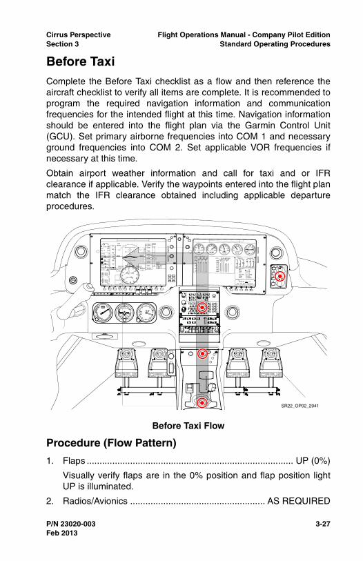
Cirrus Perspective Flight Operations Manual - Company Pilot EditionSection 3 Standard Operating Procedures
P/N 23020-003 3-27
Before TaxiComplete the Before Taxi checklist as a flow and then reference theaircraft checklist to verify all items are complete. It is recommended toprogram the required navigation information and communicationfrequencies for the intended flight at this time. Navigation informationshould be entered into the flight plan via the Garmin Control Unit(GCU). Set primary airborne frequencies into COM 1 and necessaryground frequencies into COM 2. Set applicable VOR frequencies ifnecessary at this time.
Obtain airport weather information and call for taxi and or IFRclearance if applicable. Verify the waypoints entered into the flight planmatch the IFR clearance obtained including applicable departureprocedures.
Procedure (Flow Pattern)
1. Flaps ................................................................................. UP (0%)
Visually verify flaps are in the 0% position and flap position lightUP is illuminated.
2. Radios/Avionics ..................................................... AS REQUIRED
Before Taxi Flow
SR22_OP02_2941
Feb 2013
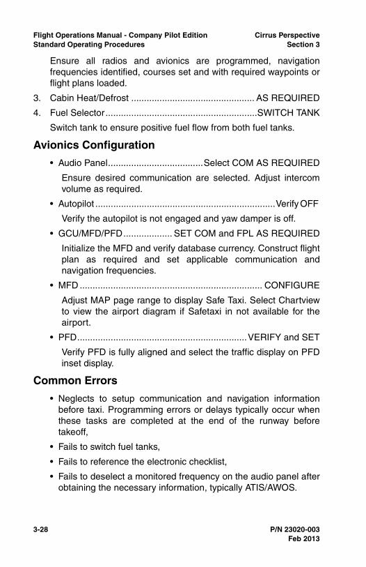
3-28 P/N 23020-003
Flight Operations Manual - Company Pilot Edition Cirrus PerspectiveStandard Operating Procedures Section 3
Ensure all radios and avionics are programmed, navigationfrequencies identified, courses set and with required waypoints orflight plans loaded.
3. Cabin Heat/Defrost ................................................ AS REQUIRED
4. Fuel Selector...........................................................SWITCH TANK
Switch tank to ensure positive fuel flow from both fuel tanks.
Avionics Configuration
• Audio Panel.....................................Select COM AS REQUIRED
Ensure desired communication are selected. Adjust intercomvolume as required.
• Autopilot ......................................................................Verify OFF
Verify the autopilot is not engaged and yaw damper is off.
• GCU/MFD/PFD................... SET COM and FPL AS REQUIRED
Initialize the MFD and verify database currency. Construct flightplan as required and set applicable communication andnavigation frequencies.
• MFD ....................................................................... CONFIGURE
Adjust MAP page range to display Safe Taxi. Select Chartviewto view the airport diagram if Safetaxi in not available for theairport.
• PFD..................................................................VERIFY and SET
Verify PFD is fully aligned and select the traffic display on PFDinset display.
Common Errors
• Neglects to setup communication and navigation informationbefore taxi. Programming errors or delays typically occur whenthese tasks are completed at the end of the runway beforetakeoff,
• Fails to switch fuel tanks,
• Fails to reference the electronic checklist,
• Fails to deselect a monitored frequency on the audio panel afterobtaining the necessary information, typically ATIS/AWOS.
Feb 2013
Cirrus Perspective Flight Operations Manual - Company Pilot EditionSection 3 Standard Operating Procedures
P/N 23020-003 3-29
Taxi-OutA cause of brake failure is the creation of excessive heat throughimproper braking practices. Riding the brakes while taxiing causes acontinuous build up of energy which may lead to excessive heat.Excessive heat causes warped brake rotors, damaged or glazedlinings, damaged o-rings, and vaporized brake fluid. To avoid brakefailure, observe the following operating and maintenance practices:
• Directional control should be maintained with rudder deflectionsupplemented with brake pressure as required,
• Use only as much power (throttle) as is necessary to achieveforward movement. 1000 RPM is enough to maintain forwardmovement under normal conditions,
• Avoid unnecessary high speed taxiing. High speed taxiing willresult in excessive demands on the brakes, increased brakewear, and the possibility of brake failure,
• Use the minimum necessary brake application to achievedirectional control,
• Do not ride the brakes. Pilots should consciously removepressure from the brakes while taxiing. Failure to do so results inexcessive heat, premature brake wear, and increased possibilityof brake failure,
• Refer to the Handling, Service and Maintenance section of thePOH or the Maintenance manual for recommendedmaintenance and inspection intervals for brakes.
Maintain high levels of situational awareness during all movement onthe airport surface to avoid a runway incursion accident. Minimizetasks such as reading checklists or folding maps while taxiing. Utilizethe Safe Taxi airport diagram to aid in situational awareness.
• WARNING •
Maximum continuous engine speed for taxiing is 1000 RPMon flat, smooth, hard surfaces. Power settings slightly above1000 RPM are permissible to start motion, for turf, softsurfaces, and on inclines. Use minimum power to maintain taxispeed.
Feb 2013
3-30 P/N 23020-003
Flight Operations Manual - Company Pilot Edition Cirrus PerspectiveStandard Operating Procedures Section 3
Procedure (Flow Pattern)
1. Parking Brake.............................................................DISENGAGE
Manually depress parking brake and ensure completely down.
2. Brakes ................................................................................ CHECK
Upon initial movement verify both brakes are functioning byapplying pressure.
3. HSI Orientation .................................................................. CHECK
Visually check HSI alignment with magnetic compass.
4. Attitude Gyro ...................................................................... CHECK
Verify gyro is erect and horizon bars are set level.
5. Turn Coordinator ................................................................ CHECK
During turns on the ground, verify the rate of turn indicatordisplays a turn in the direction of the turn and inclinometerdisplays a skid.
Common Errors
• Improper braking technique resulting in premature wear andpossible fire,
Taxi-Out Flow
SR22_OP02_2942
Feb 2013
Cirrus Perspective Flight Operations Manual - Company Pilot EditionSection 3 Standard Operating Procedures
P/N 23020-003 3-31
• Fails to set and check all instrumentation during taxi or when theaircraft is moving and turning on the ground,
• Fails to reference the taxiing checklist,
• Fails to reference Safe Taxi for situational awareness duringground operations.
Feb 2013
3-32 P/N 23020-003
Flight Operations Manual - Company Pilot Edition Cirrus PerspectiveStandard Operating Procedures Section 3
Before TakeoffComplete the Before Takeoff checklist as a do-list. Complete thechecklist at an appropriate run up area prior to departure. The BeforeTakeoff checklist will ensure the aircraft is properly configured fortakeoff and all engine and electrical indications are within parameters.Run-up items are included in this checklist. Verify engine oiltemperature reaches a minimum of 100º F prior to applying run uppower settings. Verify all engine and electrical indications are normalprior to departure.
During cold weather operations, the engine should be properlywarmed before takeoff. In most cases this is accomplished when theoil temperature has reached at least 100º F. In warm or hot weather,precautions should be taken to avoid overheating during prolongedground engine operation. Additionally, long periods of idling may causefouled spark plugs.
Procedure (Do-List)
1. Doors ..............................................................................LATCHED
Verify both top and bottom latch of each door is securely latched.Press firmly at each door latch position to determine the securityof each door.
2. CAPS Handle................................................Verify Pin REMOVED
Verify the CAPS pin is removed and stowed. Ensure cover placardis securely fastened.
3. Seat Belts and Shoulder Harness....................................SECURE
Verify the security and placement of all seat belts and shoulderharnesses of each occupant. Also, verify all occupants areproperly informed of seat belt requirements and operation.
4. Fuel Quantity.................................................................. CONFIRM
Confirm the fuel quantity is sufficient for the planned flight and fueltank quantities are balanced.
5. Fuel Selector.........................................................FULLEST TANK
Ensure the fuel selector is drawing fuel from the fullest tank.
6. Fuel Pump.............................................................. AS REQUIRED
SR20/SR22 - Fuel Pump On
SR22TN/SR22T - Fuel Pump Low Boost
Feb 2013
Cirrus Perspective Flight Operations Manual - Company Pilot EditionSection 3 Standard Operating Procedures
P/N 23020-003 3-33
7. Mixture ................................................................... AS REQUIRED
SR22 - Set the mixture full rich for sea level departures. Setmixture control lever for maximum power on takeoff for altitudeshigher then sea level. Reference the Max Power Fuel Flow placardor the top of the green arc of the fuel flow gauge for proper mixturesetting. Power must be at full-throttle for placarded values to beaccurate.
SR20/SR22TN/SR22T - Set the mixture full rich for all altitudes.
8. Flaps ...............................................................SET 50% & CHECK
Select flaps to 50% and visually verify both flaps are in positionprior to takeoff.
9. Transponder ............................................................................. SET
Set assigned squawk code if one is given, otherwise, set theappropriate code.
10. Autopilot ............................................................................. CHECK
Complete the autopilot test in accordance with the autopilot userguide.
11. Navigation Radios/GPS ........................................... Set for Takeoff
Verify radio frequencies are set to include tower/departurefrequencies. Check GPS flight plan for accuracy and correct initialwaypoint.
12. Cabin Heat/Defrost ................................................ AS REQUIRED
Set environmental controls as desired prior to takeoff.
13. Brakes................................................................................... HOLD
Firmly hold brakes. Set the parking brake if assistance is required.
14. Power Lever ................................................................... 1700 RPM
Increase power lever to 1700 RPM for engine run-up. Ensure oiltemperature is at least 100º F prior to increasing power. Select theengine page for expanded engine and electrical information duringthe engine run-up.
15. Alternator ........................................................................... CHECK
Alternator will be checked by placing greater electrical loads andturning on additional equipment below.
a. Pitot Heat.............................................................................ON
b. Navigation Lights .................................................................ON
Feb 2013
3-34 P/N 23020-003
Flight Operations Manual - Company Pilot Edition Cirrus PerspectiveStandard Operating Procedures Section 3
c. Landing Light ...................................................................... ON
d. Annunciator Lights...................................................Verify OFF
Verify that no electrical CAS messages appear on the PFD andthat positive amps are indicated.
16. Voltage ............................................................................... CHECK
Verify voltage outputs for both main buses and the essential busare in the green arcs.
17. Pitot Heat ............................................................... AS REQUIRED
Pitot heat should be turned ON for flight into IMC, flight into visiblemoisture, or whenever ambient temperatures are 5º C or less toreduce the possibility of pitot tube icing.
18. Navigation Lights.................................................... AS REQUIRED
Select navigation lights ON for night operations.
19. Landing Light ......................................................... AS REQUIRED
Select landing light ON. It is recommended to leave the landinglight on while within 10NM of the departure airport.
20. Magnetos .............................................. CHECK LEFT and RIGHT
a. Ignition Switch ................................. R, note RPM, then BOTH
b. Ignition Switch .................................. L, note RPM, then BOTH
RPM drop must not exceed 150 RPM for either magneto. RPMdifferential must not exceed 75 RPM between magnetos. If there isa doubt concerning operation of the ignition system, RPM checksat higher engine speeds will usually confirm whether a deficiencyexists. An absence of RPM drop may indicate faulty grounding ofone side of the ignition system or magneto timing set in advanceof the specified setting.
21. Engine Parameters ............................................................ CHECK
Visually verify all engine parameters are in acceptable ranges.Check Oil pressure and temperature, RPM, manifold pressure,EGT and CHT.
22. Power Lever ...................................................................1000 RPM
23. Flight Instruments, HSI and Altimeter ................. CHECK and SET
Set all flight instruments for initial course and altitude. Verify theHSI displays proper course and heading when checked with
Feb 2013
Cirrus Perspective Flight Operations Manual - Company Pilot EditionSection 3 Standard Operating Procedures
P/N 23020-003 3-35
magnetic compass. Ensure local altimeter has been set and iswithin 75 feet of field elevation.
24. Flight Controls................................................. FREE & CORRECT
Check for full range of motion of the control yoke and that controlsurface deflection corresponds to yoke deflection.
25. Trim ........................................................................ SET for Takeoff
Set electric trim in the takeoff position as displayed on control yokearm.
26. Autopilot .................................................................. DISCONNECT
Ensure PFD heading and altitude bugs are set and the autopilot isdisconnected.
GFC 700 - Press the go-around button on the throttle to engagethe Flight Director in Takeoff (TO) mode. Set the HDG and ALTbug for the assigned initial heading and altitude.
Icing Conditions Anticipated after Takeoff (FIKI):
1. ICE PROTECT System Switch ..................................................ON
2. ICE PROTECT Mode Switch ..................................... NORM/HIGH
HIGH should be selected initially to ensure critical lifting surfacesremain clear of ice during takeoff and initial climb. Once in enrouteclimb and ice buildup on unprotected surfaces is negligible, thepilot may select NORM. If rate of ice buildup on protected surfacesis unacceptable, select HIGH or MAX as appropriate.
3. PITOT HEAT Switch...................................................................ON
4. Cabin Heat ................................................................................ Hot
5. Windshield Defrost.....................................................................ON
Hot windshield defrost should be used to reduce the possibility ofice forming on the windshield.
6. Ice-Inspection Lights ................................................... As Required
Ice inspection lights will illuminate the leading edges of the wingsand horizontal stabilizer in order to monitor ice accumulation andconfirm fluid flow at night.
Common Errors
• Fails to complete checklist items in their entirety,
Feb 2013
3-36 P/N 23020-003
Flight Operations Manual - Company Pilot Edition Cirrus PerspectiveStandard Operating Procedures Section 3
• Intentionally skips items in the checklist but neglects to re-reference the checklist and complete the task before departure,
• Fails to adhere to FIKI pitot heat ground operating limitations,
• Fails to recognize an unlatched pilot or passenger door duringthe engine run-up.
Feb 2013
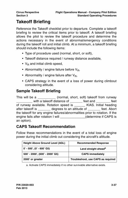
Cirrus Perspective Flight Operations Manual - Company Pilot EditionSection 3 Standard Operating Procedures
P/N 23020-003 3-37
Takeoff BriefingReference the Takeoff checklist prior to departure. Complete a takeoffbriefing to review the critical items prior to takeoff. A takeoff briefingallows the pilot to review the takeoff procedure and determine theactions necessary in the event of abnormal/emergency conditionsduring the takeoff roll and initial climb. At a minimum, a takeoff briefingshould include the following items:
• Type of procedure used (normal, short, or soft),
• Takeoff distance required / runway distance available,
• VR and initial climb speed,
• Abnormality / engine failure before VR,
• Abnormality / engine failure after VR,
• CAPS strategy in the event of a loss of power during climboutconsidering altitude.
Sample Takeoff Briefing
This will be a __________ (normal, short, soft) takeoff from runway_________ with a takeoff distance of _______ feet and ________ feetof runway available. Rotation speed is ______ KIAS. Initial headingafter takeoff is _______ degrees to an altitude of _______ feet. Abortthe takeoff for any engine failures/abnormalities prior to rotation. If theengine fails after rotation I will ______________(determine if CAPS isan option).
CAPS Takeoff Recommendation
Follow these recommendations in the event of a total loss of enginepower during the initial climb out considering the aircraft’s altitude.
Height Above Ground Level (AGL) Recommended Response
0’ - 500’, (0’ - 600’ G5) Land straight aheada
a. Activate CAPS immediately if no other survivable alternative exists.
500’ - 2000’, (600’ - 2000’ G5) CAPS immediately
2000’ or greater Troubleshoot, use CAPS as required
Feb 2013
3-38 P/N 23020-003
Flight Operations Manual - Company Pilot Edition Cirrus PerspectiveStandard Operating Procedures Section 3
Normal TakeoffUse of the Flight Director in Takeoff (TO) mode is recommended ifusing the GFC 700 autopilot. Press the Go-around button on thethrottle to engage the Flight Director in TO mode. The recommendedflap setting for a normal takeoff is 50%. Align the aircraft on the runwaycenterline and smoothly apply full power in a 4 to 5 second continuoussweep. Slight brake pressure may be required for directional controlearly in the takeoff roll in some crosswind situations. Maintaindirectional control with rudder during the takeoff roll after sufficientrudder control is available. Check engine and airspeed indicationsearly in the takeoff roll to ensure proper function. Discontinue thetakeoff by reducing the power to idle and using brakes as necessaryfor any abnormal engine or airspeed indications, sluggish acceleration,or rough engine. At VR smoothly apply back pressure to the controlyoke sufficiently enough to rotate the aircraft. Pitch the aircraft forapproximately 7º to intercept VX or VY as appropriate. Maintaincoordination with proper rudder input during the climb out.
Procedure (Flow Pattern)
1. Brakes ............................................ RELEASE (Steer with Rudder)
Initially, a slight amount of differential braking may be required fordirectional control. As airspeed increases, both feet should beremoved from toe brakes and directional control maintained withrudder inputs.
2. Power Lever ........................................................FULL FORWARD
Smoothly increase power lever full forward for maximum takeoffpower. Discontinue takeoff if any rough or sluggish acceleration isnoted. Do not confuse any detents for a full power setting. Enginespeed at full power should be approximately:
• SR20/SR22/SR22TN - 2700 RPM,
• SR22T - 2500 RPM.
SR22TN/SR22T - During the first takeoff of the day, due torelatively low engine oil temperature, engine Manifold Pressuremay exceed limits. This is acceptable, but if this occurs, pilotsshould smoothly reduce power slightly to bring MP back belowred-line. As a technique, pilots can smoothly add power on takeoffuntil reaching red line, instead of full-forward. Verify that the powerlever can be moved to full forward and remain within limits.
Feb 2013
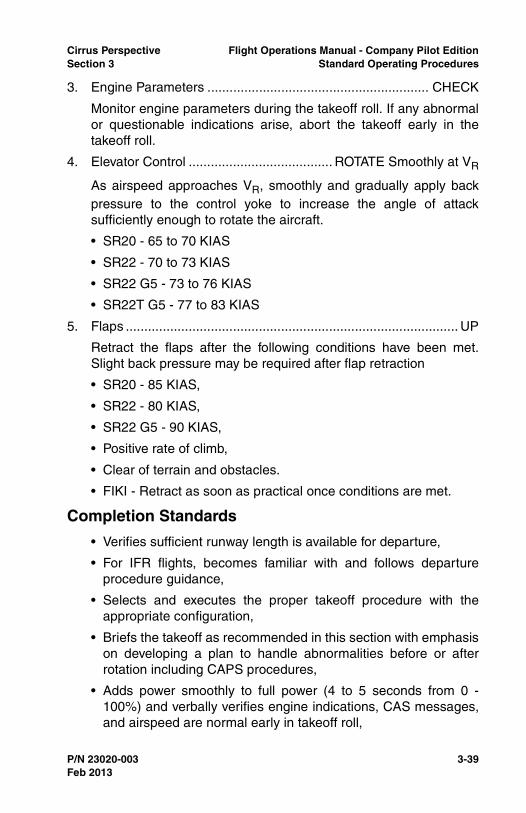
Cirrus Perspective Flight Operations Manual - Company Pilot EditionSection 3 Standard Operating Procedures
P/N 23020-003 3-39
3. Engine Parameters ............................................................ CHECK
Monitor engine parameters during the takeoff roll. If any abnormalor questionable indications arise, abort the takeoff early in thetakeoff roll.
4. Elevator Control ....................................... ROTATE Smoothly at VR
As airspeed approaches VR, smoothly and gradually apply backpressure to the control yoke to increase the angle of attacksufficiently enough to rotate the aircraft.
• SR20 - 65 to 70 KIAS
• SR22 - 70 to 73 KIAS
• SR22 G5 - 73 to 76 KIAS
• SR22T G5 - 77 to 83 KIAS
5. Flaps .......................................................................................... UP
Retract the flaps after the following conditions have been met.Slight back pressure may be required after flap retraction
• SR20 - 85 KIAS,
• SR22 - 80 KIAS,
• SR22 G5 - 90 KIAS,
• Positive rate of climb,
• Clear of terrain and obstacles.
• FIKI - Retract as soon as practical once conditions are met.
Completion Standards
• Verifies sufficient runway length is available for departure,
• For IFR flights, becomes familiar with and follows departureprocedure guidance,
• Selects and executes the proper takeoff procedure with theappropriate configuration,
• Briefs the takeoff as recommended in this section with emphasison developing a plan to handle abnormalities before or afterrotation including CAPS procedures,
• Adds power smoothly to full power (4 to 5 seconds from 0 -100%) and verbally verifies engine indications, CAS messages,and airspeed are normal early in takeoff roll,
Feb 2013
3-40 P/N 23020-003
Flight Operations Manual - Company Pilot Edition Cirrus PerspectiveStandard Operating Procedures Section 3
• Aborts the takeoff early in the takeoff roll and applies brakes asnecessary for engine parameter exceedences, CAS messages,airspeed issues, or other safety of flight issues,
• Keeps the runway center line between the main landing gearwheels through takeoff roll, rotation, and initial climb,
• Rotates smoothly at the recommended rotation speed to a climbattitude that will intercept VX or VY as desired,
• Retracts flaps as recommended and continues to pitch theaircraft for the recommended climb airspeed,
• Does not engage the autopilot before 400 feet AGL,
• Vebally announces “CAPS Available” at 500 feet AGL,
• Maintains runway alignment until 1/2 mile past the departureend of the runway unless otherwise directed by ATC.
Common Errors
• Loses directional control due to inadequate rudder inputs,
• Fails to recognize an unlatched or improperly closed door,
• Fails to promptly add full power early in the takeoff roll,
• Over rotates and uses poor airspeed control during the initialclimb,
• Fails to track over the extended runway centerline during initialclimb,
• Uses brakes excessively during the takeoff roll,
• Fails to recognize an unsafe situation early in the takeoff roll andfails to abort the takeoff promptly.
Feb 2013
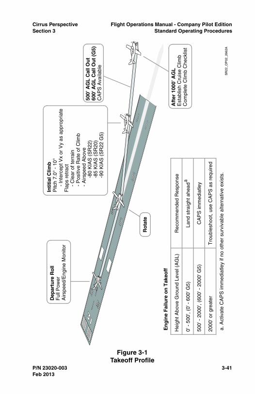
Cirrus Perspective Flight Operations Manual - Company Pilot EditionSection 3 Standard Operating Procedures
P/N 23020-003 3-41
Figure 3-1Takeoff Profile
Hei
ght A
bove
Gro
und
Leve
l (A
GL)
Rec
omm
ende
d R
espo
nse
0' -
500
', (0
' - 6
00' G
5)La
nd s
trai
ght a
head
a
500'
- 2
000'
, (60
0' -
200
0' G
5)C
AP
S im
med
iatle
y
2000
' or
grea
ter
Tro
uble
shoo
t, us
e C
AP
S a
s re
quire
d
En
gin
e F
ailu
re o
n T
akeo
ff
a. A
ctiv
ate
CA
PS
imm
edia
tley
if no
oth
er s
urvi
vabl
e al
tern
ativ
e ex
ists
.S
R22
_OP
02_2
662A
Dep
artu
re R
oll
Ful
l Pow
erA
irspe
ed/E
ngin
e M
onito
r
Rot
ate
Inti
tial
Clim
bP
itch
7.0°
- 1
0°
- In
terc
ept V
x or
Vy
as a
ppro
pria
teF
laps
ret
ract
-
Cle
ar o
f ter
rain
-
Pos
itive
Rat
e of
Clim
b
- A
irspe
ed A
bove
-
80 K
IAS
(S
R22
)
-85
KIA
S (
SR
20)
-
90 K
IAS
(S
R22
G5)
Aft
er 1
000’
AG
LE
stab
lish
Cru
ise
Clim
bC
ompl
ete
Clim
b C
heck
list
500’
AG
L C
all O
ut
600'
AG
L C
all O
ut
(G5)
CA
PS
Ava
ilabl
e
Feb 2013

3-42 P/N 23020-003
Flight Operations Manual - Company Pilot Edition Cirrus PerspectiveStandard Operating Procedures Section 3
Short-Field TakeoffUse the short-field technique to maximize takeoff performance andminimize takeoff ground roll. Set Flaps to 50% for a short-field takeoff.Align the aircraft on the runway centerline as close as possible to theend of the runway. Apply sufficient brake pressure and smoothly applyfull power. Check engine indications and ensure full power beforereleasing the brakes. Steer with rudder only in order to minimize theground roll distance. Rotate the aircraft at VR smoothly and pitch forthe obstacle clearance speed if an obstacle is present. Pitch for VYafter clearing obstacles.
1. Flaps ........................................................................................50%
Set flaps to 50% and visually verify both flaps are in position priorto takeoff.
2. Brakes ...................................................................................HOLD
Hold brakes firmly, do not allow the aircraft to roll.
3. Power Lever ........................................................FULL FORWARD
Smoothly increase power lever full forward for maximum takeoffpower. Discontinue takeoff if any rough or sluggish acceleration isnoted. Do not confuse any detents for a full power setting. Enginespeed at full power should be approximately:
• SR20/SR22/SR22TN - 2700 RPM,
• SR22T - 2500 RPM.
4. Mixture .....................................................................................SET
SR22 - Set the mixture full rich for sea-level departures. Setmixture control lever for maximum power on takeoff for altitudeshigher then sea level. Reference the Max Power Fuel Flow placardor the top of the green arc of the fuel flow gauge for proper mixturesetting. Power must be at full-throttle for placarded values to beaccurate.
SR20/SR22TN/SR22T - Set the mixture to full rich for all altitudes.
5. Engine Parameters ............................................................ CHECK
Check all engine parameters prior to releasing the brakes. If anyabnormal or questionable indications arise, consider abortingtakeoff.
6. Brakes ............................................................................ RELEASE
Feb 2013
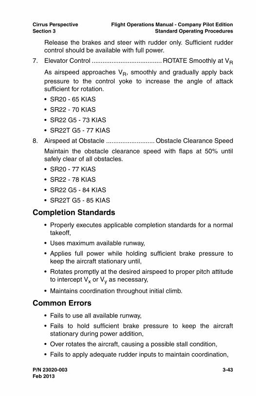
Cirrus Perspective Flight Operations Manual - Company Pilot EditionSection 3 Standard Operating Procedures
P/N 23020-003 3-43
Release the brakes and steer with rudder only. Sufficient ruddercontrol should be available with full power.
7. Elevator Control ....................................... ROTATE Smoothly at VR
As airspeed approaches VR, smoothly and gradually apply backpressure to the control yoke to increase the angle of attacksufficient for rotation.
• SR20 - 65 KIAS
• SR22 - 70 KIAS
• SR22 G5 - 73 KIAS
• SR22T G5 - 77 KIAS
8. Airspeed at Obstacle ........................... Obstacle Clearance Speed
Maintain the obstacle clearance speed with flaps at 50% untilsafely clear of all obstacles.
• SR20 - 77 KIAS
• SR22 - 78 KIAS
• SR22 G5 - 84 KIAS
• SR22T G5 - 85 KIAS
Completion Standards
• Properly executes applicable completion standards for a normaltakeoff,
• Uses maximum available runway,
• Applies full power while holding sufficient brake pressure tokeep the aircraft stationary until,
• Rotates promptly at the desired airspeed to proper pitch attitudeto intercept Vx or Vy as necessary,
• Maintains coordination throughout initial climb.
Common Errors
• Fails to use all available runway,
• Fails to hold sufficient brake pressure to keep the aircraftstationary during power addition,
• Over rotates the aircraft, causing a possible stall condition,
• Fails to apply adequate rudder inputs to maintain coordination,
Feb 2013
3-44 P/N 23020-003
Flight Operations Manual - Company Pilot Edition Cirrus PerspectiveStandard Operating Procedures Section 3
• Prematurely retracts flaps, causing excessive sink rates.
Feb 2013

Cirrus Perspective Flight Operations Manual - Company Pilot EditionSection 3 Standard Operating Procedures
P/N 23020-003 3-45
Soft-Field TakeoffSoft or rough field takeoffs are executed using 50% flaps. Add 20% tothe takeoff ground roll distance for dry grass runways and 30% for wetgrass. Ensure the quality of the runway is adequate to support theaircraft. Avoid runways with long grass, soggy soil and large ruts orholes. Higher power settings will be required to taxi on grass surfaces.Hold full back pressure on the control yoke while taxiing and during theinitial takeoff roll to reduce the pressure on the nose wheel. Reducethe back pressure slightly once the nose wheel lifts off the ground.Hold the aircraft in a nose up attitude until the aircraft becomesairborne. Once airborne reduce back pressure as necessary to remainin ground effect or within 20 feet of the surface. Accelerate the aircraftto VX (for obstacles clearance) or VY before climbing out of groundeffect.
Completion Standards
• Properly executes applicable completion standards for a normaltakeoff,
• Verifies the runway condition supports safe takeoff by taxiingover the runway prior to depart,
• Holds the elevator full aft during taxi and takeoff roll whensufficient elevator authority exists,
• Holds the aircraft at a high angle (approx 5 to 7.5 degrees) whensufficient airflow is available over the elevator,
• Relaxes back pressure during the takeoff roll and does not overrotate the aircraft,
• Reduces pitch when the aircraft becomes airborne to maintainin ground effect until VX or VY is reached,
• Climbs out at VXor VY as necessary.
Common Errors
• Fails to apply sufficient back pressure during taxi or takeoff roll,
• Over rotates the aircraft during the takeoff roll or at rotation,
• Fails to apply sufficient rudder input to maintain directionalcontrol,
• Climbs out of ground effect too quickly.
Feb 2013
3-46 P/N 23020-003
Flight Operations Manual - Company Pilot Edition Cirrus PerspectiveStandard Operating Procedures Section 3
Crosswind Takeoff TechniquePartially deflect the ailerons into the wind during a crosswind takeoff.Maintain directional control with proper rudder input. Allow the aircraftto accelerate to a speed slightly higher then VR prior to rotation. Liftthe aircraft off the ground slightly quicker than with a normal takeoff.Shortly after rotation, crab the aircraft into the wind to track the aircraftalong the runway centerline. Maintain coordination during climb withproper rudder input.
Completion Standards
• Properly executes applicable completion standards for a normaltakeoff,
• Recognizes the need for the crosswind technique,
• Applies aileron input into the crosswind and uses rudder tomaintain runway alignment during the takeoff roll and rotation,
• Reduces the amount of aileron deflection as the aircraftaccelerates and aileron control effectiveness increases,
• Establishes coordinated flight and a wind correction angleshortly after takeoff and tracks over the runway centerline duringinitial climb.
Common Errors
• Fails to identify a crosswind situation,
• Fails to apply correct aileron inputs resulting in drift or side loadson the landing gear,
• Fails to establish a wind correction angle after rotation andallows the aircraft to drift away from the runway center line,
• Fails to resume coordinated flight after rotation resulting in across-control situation,
Feb 2013
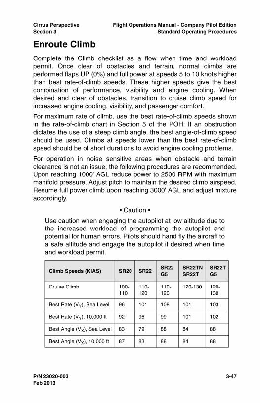
Cirrus Perspective Flight Operations Manual - Company Pilot EditionSection 3 Standard Operating Procedures
P/N 23020-003 3-47
Enroute ClimbComplete the Climb checklist as a flow when time and workloadpermit. Once clear of obstacles and terrain, normal climbs areperformed flaps UP (0%) and full power at speeds 5 to 10 knots higherthan best rate-of-climb speeds. These higher speeds give the bestcombination of performance, visibility and engine cooling. Whendesired and clear of obstacles, transition to cruise climb speed forincreased engine cooling, visibility, and passenger comfort.
For maximum rate of climb, use the best rate-of-climb speeds shownin the rate-of-climb chart in Section 5 of the POH. If an obstructiondictates the use of a steep climb angle, the best angle-of-climb speedshould be used. Climbs at speeds lower than the best rate-of-climbspeed should be of short durations to avoid engine cooling problems.
For operation in noise sensitive areas when obstacle and terrainclearance is not an issue, the following procedures are recommended.Upon reaching 1000' AGL reduce power to 2500 RPM with maximummanifold pressure. Adjust pitch to maintain the desired climb airspeed.Resume full power climb upon reaching 3000' AGL and adjust mixtureaccordingly.
• Caution •
Use caution when engaging the autopilot at low altitude due tothe increased workload of programming the autopilot andpotential for human errors. Pilots should hand fly the aircraft toa safe altitude and engage the autopilot if desired when timeand workload permit.
Climb Speeds (KIAS) SR20 SR22SR22 G5
SR22TNSR22T
SR22T G5
Cruise Climb 100-110
110-120
110-120
120-130 120-130
Best Rate (VY), Sea Level 96 101 108 101 103
Best Rate (VY), 10,000 ft 92 96 99 101 102
Best Angle (VX), Sea Level 83 79 88 84 88
Best Angle (VX), 10,000 ft 87 83 88 84 88
Feb 2013

3-48 P/N 23020-003
Flight Operations Manual - Company Pilot Edition Cirrus PerspectiveStandard Operating Procedures Section 3
Procedure (Flow Pattern)
1. Climb Power .............................................................................SET
Set climb power considering noise abatement procedures. Normalclimbs are made with full power.
2. Flaps ................................................................................Verify UP
Verify flaps have been retracted to 0%. If not, verify below VFE andensure the following criteria has been met before retracting theflaps:
• SR20 - 85 KIAS,
• SR22 - 80 KIAS,
• SR22 G5 - 90 KIAS,
• Positive rate of climb,
• Clear of terrain and obstacles.
3. Mixture ................................................................... AS REQUIRED
Set power, mixture, and airspeed per table.
4. Fuel Pump................................................................... As Required
SR20 - OFF
Enroute Climb Flow
SR22_OP02_2943
Feb 2013
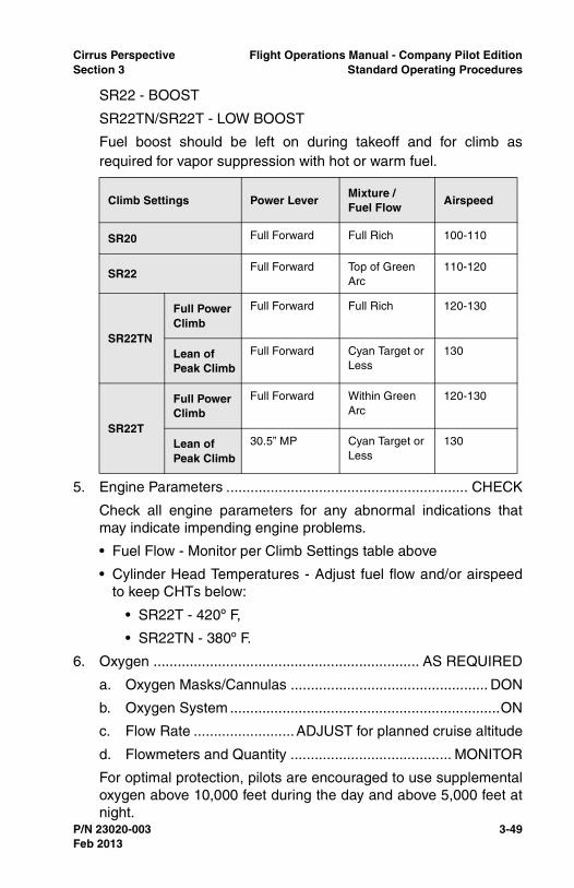
Cirrus Perspective Flight Operations Manual - Company Pilot EditionSection 3 Standard Operating Procedures
P/N 23020-003 3-49
SR22 - BOOST
SR22TN/SR22T - LOW BOOST
Fuel boost should be left on during takeoff and for climb asrequired for vapor suppression with hot or warm fuel.
5. Engine Parameters ............................................................ CHECK
Check all engine parameters for any abnormal indications thatmay indicate impending engine problems.
• Fuel Flow - Monitor per Climb Settings table above
• Cylinder Head Temperatures - Adjust fuel flow and/or airspeedto keep CHTs below:
• SR22T - 420º F,
• SR22TN - 380º F.
6. Oxygen .................................................................. AS REQUIRED
a. Oxygen Masks/Cannulas ................................................. DON
b. Oxygen System ...................................................................ON
c. Flow Rate .........................ADJUST for planned cruise altitude
d. Flowmeters and Quantity ........................................ MONITOR
For optimal protection, pilots are encouraged to use supplementaloxygen above 10,000 feet during the day and above 5,000 feet atnight.
Climb Settings Power LeverMixture / Fuel Flow
Airspeed
SR20 Full Forward Full Rich 100-110
SR22Full Forward Top of Green
Arc110-120
SR22TN
Full Power Climb
Full Forward Full Rich 120-130
Lean of Peak Climb
Full Forward Cyan Target or Less
130
SR22T
Full Power Climb
Full Forward Within Green Arc
120-130
Lean of Peak Climb
30.5” MP Cyan Target or Less
130
Feb 2013
3-50 P/N 23020-003
Flight Operations Manual - Company Pilot Edition Cirrus PerspectiveStandard Operating Procedures Section 3
Cannulas are not approved above 18,000 feet MSL becausecannulas fail to deliver adequate levels of oxygen. Pilots must usea mask that is certified above 18,000 feet MSL when operatingabove FL180.
If using a pulse oximeter, adjust flow rate to keep oxygensaturation above 90%. Pilots are encouraged to use pulseoximeter and check saturation levels every 10 to 15 minutes.
Avionics Configuration
• Autopilot - Engage modes as desired above 400 feet AGL whentime and workload permit,
• MFD - Complete Climb Checklist, monitor map for situationalawareness,
• PFD - Monitor aircraft flight parameters and system status.
Completion Standards
• Maintains positive aircraft control,
• Retracts the flaps when climbing, clear of obstacles, and at theprescribed airspeed,
• Maintains desired airspeed within +10/-5 KIAS,
• Abides by local noise abatement procedures if applicable,
• Follows instrument departure procedures if applicable,
• Follows ATC instructions and clearances if applicable,
• Completes the Climb checklist as a flow and references thechecklist when workload permits,
• Manages engine temperatures through airspeed/pitch control,proper power and mixture settings as recommended by theAFM,
• At pilot’s discretion, uses the autopilot to reduce workload,
• Uses proper scanning techniques and Traffic Alert System forcollision avoidance,
• Uses supplemental oxygen at the appropriate time during theclimb,
• Maintains appropriate cloud clearances during VMC climbs,
• Operates FIKI system properly when flying through icingconditions during departure.
Feb 2013

Cirrus Perspective Flight Operations Manual - Company Pilot EditionSection 3 Standard Operating Procedures
P/N 23020-003 3-51
Common Errors
• Inability to maintain desired airspeed while hand flying,
• Over dependence on the autopilot for controlled flight,
• Engaging the autopilot before 400 feet AGL,
• Fails to engage the proper mode of the autopilot,
• Fails to complete Climb checklist items,
• Fails to divide attention and look outside during VFR climbs,
• Fails to become familiar with, program, or follow applicabledeparture procedures,
• Neglects to monitor engine parameters during climb,
• Fails to set mixture control as required during climb,
• Fails to abide by sterile cockpit rules during climbout,
• Fails to monitor for icing conditions.
Feb 2013

3-52 P/N 23020-003
Flight Operations Manual - Company Pilot Edition Cirrus PerspectiveStandard Operating Procedures Section 3
CruiseComplete the Cruise checklist as a flow when time and workloadpermit. Allow the aircraft to accelerate to cruise speeds before settingthe desired cruise power setting. Ensure adequate fuel reservesremain for the intended destination. Normal cruise power settings arebetween 55% - 85% power with mixture set for best power or besteconomy. Turbo aircraft will always cruise at best economy.
Engine Break-In
For engine break-in of normally-aspirated engines, cruise at aminimum of 75% best power, rich of peak EGT, until the engine hasbeen operated for at least 25 hours or until oil consumption stabilizes.Turbo aircraft may be operated at best economy, lean of peak EGT,with a power setting greater than 75% during engine break-in.Operation at higher power will ensure proper seating of the rings, andis applicable to new engines, and engines in service following cylinderreplacement or top overhaul of one or more cylinders.
Procedure (Flow Pattern)
1. Fuel Pump....................................................OFF / AS REQUIRED
Cruise Flow
SR22_OP02_2944
Feb 2013
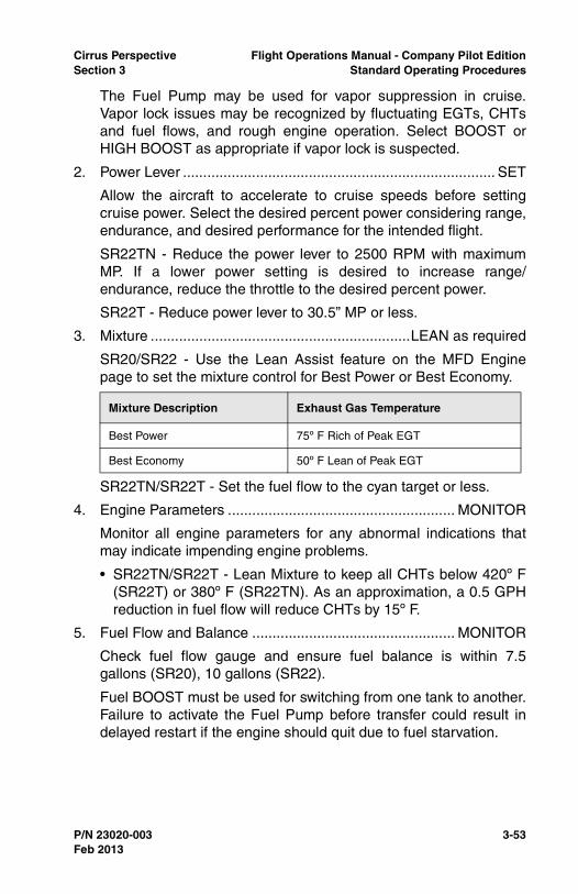
Cirrus Perspective Flight Operations Manual - Company Pilot EditionSection 3 Standard Operating Procedures
P/N 23020-003 3-53
The Fuel Pump may be used for vapor suppression in cruise.Vapor lock issues may be recognized by fluctuating EGTs, CHTsand fuel flows, and rough engine operation. Select BOOST orHIGH BOOST as appropriate if vapor lock is suspected.
2. Power Lever ............................................................................. SET
Allow the aircraft to accelerate to cruise speeds before settingcruise power. Select the desired percent power considering range,endurance, and desired performance for the intended flight.
SR22TN - Reduce the power lever to 2500 RPM with maximumMP. If a lower power setting is desired to increase range/endurance, reduce the throttle to the desired percent power.
SR22T - Reduce power lever to 30.5” MP or less.
3. Mixture ................................................................LEAN as required
SR20/SR22 - Use the Lean Assist feature on the MFD Enginepage to set the mixture control for Best Power or Best Economy.
SR22TN/SR22T - Set the fuel flow to the cyan target or less.
4. Engine Parameters ........................................................ MONITOR
Monitor all engine parameters for any abnormal indications thatmay indicate impending engine problems.
• SR22TN/SR22T - Lean Mixture to keep all CHTs below 420º F(SR22T) or 380º F (SR22TN). As an approximation, a 0.5 GPHreduction in fuel flow will reduce CHTs by 15º F.
5. Fuel Flow and Balance .................................................. MONITOR
Check fuel flow gauge and ensure fuel balance is within 7.5gallons (SR20), 10 gallons (SR22).
Fuel BOOST must be used for switching from one tank to another.Failure to activate the Fuel Pump before transfer could result indelayed restart if the engine should quit due to fuel starvation.
Mixture Description Exhaust Gas Temperature
Best Power 75º F Rich of Peak EGT
Best Economy 50º F Lean of Peak EGT
Feb 2013
3-54 P/N 23020-003
Flight Operations Manual - Company Pilot Edition Cirrus PerspectiveStandard Operating Procedures Section 3
Icing Conditions (FIKI)Even with an aircraft that is certified to operate in known icingconditions, prolonged flight in icing conditions should be avoided.Pilots should use good pre-flight planning to choose a route andaltitude that will minimize time in icing conditions. If this is not possible,consider delaying or cancelling the flight. Pilots should always have anescape option in case of a system malfunction or severe iceencounter. This escape could be above or below the cloud layer orbelow the freezing level. Note that in some conditions the freezinglevel may be at the surface or below the MEA.
Pilots may generally escape the worst icing conditions in stratusclouds by making an altitude change of more than 3000 ft. While flyingthrough cumulus clouds, altitude changes may not be effective andlateral deviations may be necessary to escape the worst icingconditions.
During icing encounters in cruise, increase engine power to maintaincruise speed as ice accumulates on the unprotected areas and causesthe aircraft to slow down. Sacrifice altitude if necessary in order tomaintain safe flying speed.
The autopilot may be used in icing conditions. However, every 30minutes the autopilot should be disconnected to detect any out-of-trimconditions caused by ice buildup. If significant out-of-trim or otheranomalous conditions are detected, the autopilot should remain off forthe remainder of the icing encounter. When disconnecting theautopilot with ice accretions on the airplane, the pilot should be alertfor out-of-trim forces.
Ice Formation Determination
Typically, a leading edge with a small radius will collect ice morequickly than a leading edge with a large radius. To help monitorpossible ice accumulation, a thin metal tab is attached to the outboardend of the right-hand and left-hand stall strips. In some icingconditions this tab may be the first place that airframe ice accretion isnoticeable. Additionally, refer to other areas of the aircraft, such as thehorizontal tail and lower windscreen, to aid in determining if ice isaccreting to the aircraft.
• Caution •
Ice accumulations on protected areas are abnormal.
Feb 2013
Cirrus Perspective Flight Operations Manual - Company Pilot EditionSection 3 Standard Operating Procedures
P/N 23020-003 3-55
De-Icing Procedures
1. Pitot Heat .........................................................................Verify ON
2. Ice Protect System Switch .........................................................ON
3. Ice Protect Mode Switch ........................................ AS REQUIRED
Select NORM or HIGH as conditions dictate.
If icing conditions are inadvertently encountered, press MAX toinitially dissipate ice accumulation, then select NORM or HIGH asrequired by ice accumulation.
4. WIND SHLD Push-Button .............................. PRESS As Required
Use the windshield ice protection when residual fluid that is slungoff of the propeller will not keep the windshield free of ice. Due tothe temporary reduction in visibility, do not use the windshieldsprayer within 30 seconds prior to landing.
5. Airspeed................Maintain 95-177 KIAS and less than 204 KTAS
Maintaining airspeed within this range will ensure proper pressuredistribution over the wings and effective anti-ice system operation.Adjust final approach airspeed to 95 KIAS with 50% flaps whenlanding with ice adhering to the aircraft.
6. Flaps .......................................................................................... UP
Keep flaps in the up position until required for landing. Limit flapextension for landing to 50%.
7. Ice Inspection Lights .............................................. AS REQUIRED
Ice inspection lights will illuminate the leading edges of the wingsand horizontal stabilizer in order to monitor ice accumulation andconfirm fluid flow at night.
8. Cabin Heat ...............................................................................HOT
9. Windshield Defrost.....................................................................ON
Windshield defrost set to hot will help to keep the windshield freeof ice.
10. Anti-ice Fluid Quantity.................................................... MONITOR
Ensure adequate quantity to complete flight.
11. Ice Accumulation............................................................ MONITOR
If ice accretion rate is higher than desired or ice is not shedding,select a higher mode of operation. If ice accretions do not shed,
Feb 2013

3-56 P/N 23020-003
Flight Operations Manual - Company Pilot Edition Cirrus PerspectiveStandard Operating Procedures Section 3
select PUMP BKUP and perform the Anti-Ice System FailureChecklist. Exit icing conditions immediately if ice cannot be shed.
Avionics Configuration
• Autopilot - Ensure correct modes are engaged if desired,
• GCU/Flight Plan - ensure proper navigation is set,
• MFD - Use Lean Assist to lean the mixture. Complete the CruiseChecklist,
• PFD - Monitor aircraft flight parameters and system status.
Completion Standards
• Allows the aircraft to accelerate before setting cruise power,
• Adheres to procedures described in the AFM for setting cruisepower and mixture controls,
• Completes Cruise checklist,
• Monitors engine parameters and manages accordingly,
• Establishes the aircraft on the intended course and altitude,
• Ensures adequate fuel reserves will be available when reachingthe destination, monitors fuel status throughout the flight,
• Monitors enroute and destination weather periodically,
• Plans arrival and descent before descent is required,
• Keeps the aircraft within fuel balance limitations,
• Monitors the physical state of passengers during cruise,especially important for flights above 10,000 feet MSL,
• Identifies situations that require an altitude or route change,such as: weather, airspace, and traffic,
• Maintains altitude +/-200 feet and headings +/-15 degrees.
Common Errors
• Exhibits tendencies toward complacency, and fails to monitorflight status, passengers, pilot fatigue, and weather.
• Forgets to plan descents and prepare for arrival,
• Fails to recognize an inadequate fuel quantity situation orexceed the maximum fuel imbalance,
• Fails to set the mixture throughout the descent properly.
Feb 2013
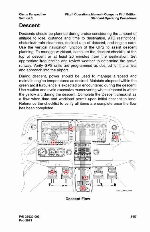
Cirrus Perspective Flight Operations Manual - Company Pilot EditionSection 3 Standard Operating Procedures
P/N 23020-003 3-57
DescentDescents should be planned during cruise considering the amount ofaltitude to lose, distance and time to destination, ATC restrictions,obstacle/terrain clearance, desired rate of descent, and engine care.Use the vertical navigation function of the GPS to assist descentplanning. To manage workload, complete the descent checklist at thetop of descent or at least 20 minutes from the destination. Setappropriate frequencies and review weather to determine the activerunway. Verify GPS units are programmed as desired for the arrivaland approach into the airport.
During descent, power should be used to manage airspeed andmaintain engine temperatures as desired. Maintain airspeed within thegreen arc if turbulence is expected or encountered during the descent.Use caution and avoid excessive maneuvering when airspeed is withinthe yellow arc during the descent. Complete the Descent checklist asa flow when time and workload permit upon initial descent to land.Reference the checklist to verify all items are complete once the flowhas been completed.
Descent Flow
SR22_OP02_2945
Feb 2013
3-58 P/N 23020-003
Flight Operations Manual - Company Pilot Edition Cirrus PerspectiveStandard Operating Procedures Section 3
Procedure (Flow Pattern)
1. Oxygen................................................................... AS REQUIRED
2. Altimeter...................................................................................SET
Verify the proper altimeter setting has been set into the PFD and inthe standby altimeter.
3. Cabin Heat/Defrost ................................................ AS REQUIRED
4. Landing Light ............................................................................ ON
The landing light should be selected on for visibility to others at thetop of the descent or within 10NM from the destination. If in IMC,consider leaving off to reduce light reflection in the cabin.
5. Fuel System ....................................................................... CHECK
Ensure fuel is balanced and selected to the fullest tank.
6. Mixture ................................................................... AS REQUIRED
SR20 - It is not necessary to adjust the mixture during descent.
SR22 - Consider altitude when setting mixture for descent. Fullmixture settings at high altitudes may lead to engine roughness orflooding resulting in engine loss.
SR22TN/SR22T - Set the fuel flow to the cyan target or less.
7. Brake Pressure .................................................................. CHECK
Apply pressure to each toe brake and ensure resistance is felt. Asoft or mushy feeling in the brakes could indicate a brake failure.
Rapid Descent (SR22TN/SR22T)
1. Power Lever ......................................... REDUCE MP to 18-20” Hg
Pitch the aircraft to the top of the green arc on the airspeedindicator,
2. Mixture ..............................................Maintain CHTs above 240º F
Avionics Configuration
• Autopilot - Engage the modes on autopilot for descent asdesired,
• GCU/Flight Plan - Verify that the correct navigation informationis set,
• MFD - Complete the Descent checklist, monitor the map forsituational awareness,
Feb 2013
Cirrus Perspective Flight Operations Manual - Company Pilot EditionSection 3 Standard Operating Procedures
P/N 23020-003 3-59
• PFD - Set Altitude Bug as appropriate for the descent. Monitorthe aircraft flight parameters.
Completion Standards
• Starts descent at the calculated top of descent and at thecalculated descent rate,
• Maintains positive aircraft control with emphasis on airspeedand vertical descent rate,
• Adheres to ATC and airspace restrictions throughout thedescent,
• Maintains airspeed below VNO while descending in turbulentconditions or if turbulence is expected in the descent,
• Recognizes a steep descent, usually due to ATC restrictions,and manages airspeed and descent rates accordingly,
• Monitors for icing conditions during descents in IMC,
• Uses the correct modes of the autopilot to assist in workloadmanagement while preparing for arrival/landing,
• Completes the Descent checklist as flow pattern and referencesthe checklist when workload permits.
Common Errors
• Fails to start the descent at the appropriate time using thenecessary descent rate,
• Fails to consider passenger comfort when selecting descentrates and/or airspeed,
• Neglects to complete the Descent checklist items in a timelymanner,
• Fails to complete airport arrival tasks and planning,
• Fails to slow to a speed that allows the pilot to perform astabilized approach in a timely manner,
• Controls or reduces power too aggressively or abruptly,
• Allows airspeed to decay unknowingly during level-off with lowpower settings,
• Does not trim the aircraft for changes in airspeed throughout thedescent.
Feb 2013
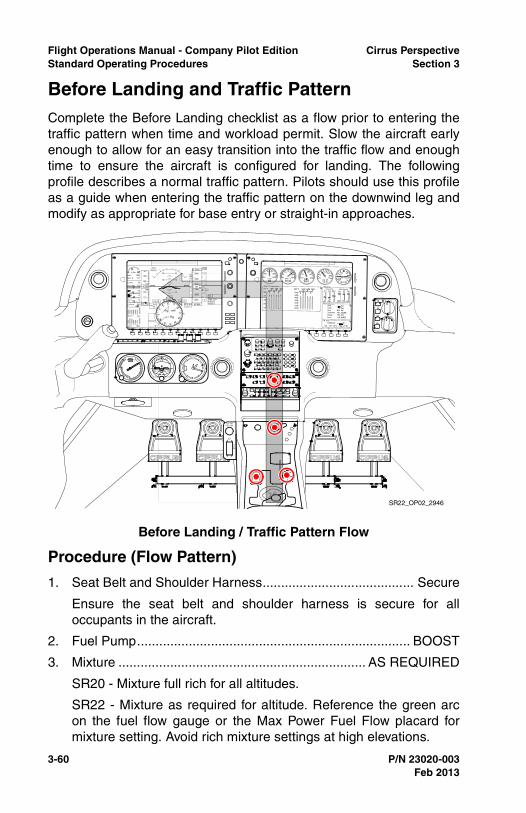
3-60 P/N 23020-003
Flight Operations Manual - Company Pilot Edition Cirrus PerspectiveStandard Operating Procedures Section 3
Before Landing and Traffic PatternComplete the Before Landing checklist as a flow prior to entering thetraffic pattern when time and workload permit. Slow the aircraft earlyenough to allow for an easy transition into the traffic flow and enoughtime to ensure the aircraft is configured for landing. The followingprofile describes a normal traffic pattern. Pilots should use this profileas a guide when entering the traffic pattern on the downwind leg andmodify as appropriate for base entry or straight-in approaches.
Procedure (Flow Pattern)
1. Seat Belt and Shoulder Harness......................................... Secure
Ensure the seat belt and shoulder harness is secure for alloccupants in the aircraft.
2. Fuel Pump.......................................................................... BOOST
3. Mixture ................................................................... AS REQUIRED
SR20 - Mixture full rich for all altitudes.
SR22 - Mixture as required for altitude. Reference the green arcon the fuel flow gauge or the Max Power Fuel Flow placard formixture setting. Avoid rich mixture settings at high elevations.
Before Landing / Traffic Pattern Flow
SR22_OP02_2946
Feb 2013

Cirrus Perspective Flight Operations Manual - Company Pilot EditionSection 3 Standard Operating Procedures
P/N 23020-003 3-61
SR22TN/SR22T - Mixture full rich for all altitudes.
The mixture should be placed in the landing position prior toentering the traffic pattern or prior to the FAF on an instrumentapproach.
4. Flaps ...................................................................... AS REQUIRED
Reference the Traffic Pattern Profile or Approach Profile forinformation on the appropriate use of flaps
5. Autopilot ................................................................. AS REQUIRED
It is recommended to disconnect the autopilot prior to entering thetraffic pattern. Ensure yaw damper is off prior to landing.
Avionics Configuration
• Autopilot - Disengage the autopilot prior to entering the trafficpattern, verify the yaw damper is disconnected,
• MFD - Complete the Before Landing checklist, monitor Map forsituational awareness,
• PFD - Monitor aircraft flight parameters.
Feb 2013
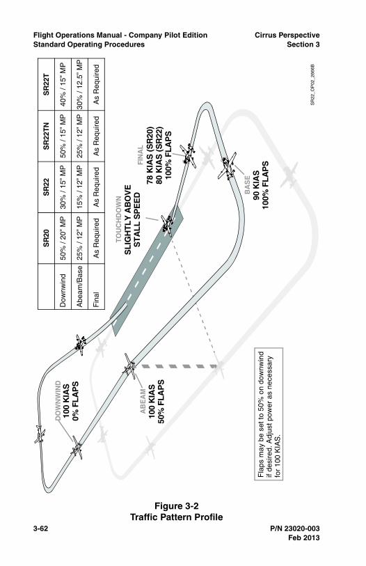
3-62 P/N 23020-003
Flight Operations Manual - Company Pilot Edition Cirrus PerspectiveStandard Operating Procedures Section 3
Figure 3-2Traffic Pattern Profile
Dow
nwin
d
Abe
am/B
ase
Fin
alA
s R
equi
red
As
Req
uire
dA
s R
equi
red
25%
/ 12
” M
P15
% /
12”
MP
25%
/ 12
” M
P
50%
/ 20
” M
P30
% /
15”
MP
50%
/ 15
” M
P
SR
20S
R22
SR
22TN
As
Req
uire
d
30%
/ 12
.5”
MP
40%
/ 15
” M
P
SR
22T
SL
IGH
TL
Y A
BO
VE
ST
AL
L S
PE
ED
TO
UC
HD
OW
N
Fla
ps m
ay b
e se
t to
50%
on
dow
nwin
dif
desi
red.
Adj
ust p
ower
as
nece
ssar
yfo
r 10
0 K
IAS
.
DO
WN
WIN
D10
0 K
IAS
0% F
LA
PS
AB
EA
M10
0 K
IAS
50%
FLA
PS
FIN
AL
78 K
IAS
(S
R20
)80
KIA
S (
SR
22)
100%
FL
AP
S
BA
SE
90 K
IAS
100%
FL
AP
S
SR
22_O
P02
_266
6B
Feb 2013
Cirrus Perspective Flight Operations Manual - Company Pilot EditionSection 3 Standard Operating Procedures
P/N 23020-003 3-63
Completion Standards
• Slows the aircraft to recommended downwind speed before mid-field downwind,
• Completes Before Landing checklist before entering the trafficpattern,
• Properly communicates with ATC or other traffic in the localarea,
• Enters the traffic pattern complying with local procedures, ATCclearances, and prescribed traffic pattern procedures,
• Maintains traffic pattern altitude on downwind +/-100 feet,airspeed +/-10 KIAS,
• Establishes a controlled descent, manages aircraft configurationand airspeed as described above with airspeed +/-5 KIAS
• Maintains proper spacing from other aircraft in the traffic pattern,
• Disconnects the autopilot before entering into the traffic pattern.
Common Errors
• Carries excessive speed on the downwind leg due to improperplanning and power management,
• Enters downwind leg above traffic pattern altitude due toimproper descent planning and/or power management,
• Fails to follow standardized power and aircraft configurationchanges in the traffic pattern,
• Fails to compensate for ballooning when deploying the flaps,resulting in an excess loss of airspeed and/or altitude gain,
• Fails to maintain coordinated flight throughout the traffic pattern,
• Has trouble visualizing and becoming oriented with runwayconfiguration resulting in confusion and non-standard patternentry,
• Exhibits poor airspeed control during downwind, base, and final,
• Fails to reduce power and pitch on the upwind or crosswind legresulting in excessive airspeed and/or altitude above trafficpattern altitude.
Feb 2013
3-64 P/N 23020-003
Flight Operations Manual - Company Pilot Edition Cirrus PerspectiveStandard Operating Procedures Section 3
Stabilized Approach DefinitionA stabilized approach is critical to a safe, successful landing. Astabilized approach is characterized by a constant angle and constantrate of descent approach profile ending near the touch-down point.Stabilized approach criteria apply to all approaches including practicepower-off approaches.
VFR Stabilized Approach Definition
All briefings and appropriate checklists should be completed by 500'AGL in visual conditions.
A VFR approach is considered stabilized when all of the followingcriteria are achieved by 500' AGL:
• Proper airspeed,
• Correct flight path,
• Correct aircraft configuration for phase of flight,
• Appropriate power setting for aircraft configuration,
• Normal angle and rate of descent,
• Only minor corrections are required to correct deviations.
A go-around must be executed if the above conditions are not met andthe aircraft is not stabilized by 500' AGL.
IFR Stabilized Approach Definition
All briefings and appropriate checklists should be completed prior tothe IAF for instrument conditions.
An IFR approach is considered stabilized when all of the followingcriteria are met prior to the FAF, and continues to touch-down:
• Proper airspeed,
• Correct flight path,
• Correct aircraft configuration for phase of flight,
• Appropriate power setting for aircraft configuration,
• Normal angle and rate of descent,
• Only minor corrections with pitch and power are required tocorrect airspeed and glide path deviations,
• Normal bracketing (+/- 5º) is used to correct for lateral andvertical navigation deviations.
Feb 2013
Cirrus Perspective Flight Operations Manual - Company Pilot EditionSection 3 Standard Operating Procedures
P/N 23020-003 3-65
• Note •
Keep flaps at 50% for landing unless the runway is in sight andlanding is assured before 500’ AGL. Ensure sufficient runwaylength is available for a 50% flap landing.
A missed approach must be executed if the above conditionsare not maintained during an instrument approach.
Feb 2013
3-66 P/N 23020-003
Flight Operations Manual - Company Pilot Edition Cirrus PerspectiveStandard Operating Procedures Section 3
Instrument Approach ProceduresThe following Approach sections outline the operating procedures forexecuting precision and nonprecision approaches. The informationdescribes the best way to configure the aircraft for given instrumentprocedures, complete checklist items, and configure avionics in Cirrusaircraft. The purpose of this section is to supplement the information inthe POH and provide greater guidance on the completion of variousinstrument procedures in the aircraft. The techniques outlined in thissection may not be inclusive of all variables encountered in thenational airspace system. Pilots should follow these standardprocedures when applicable and exercise good judgment for non-standard procedures. To reduce workload during the descent andinstrument approach procedure follow these recommendations.
• Obtain destination weather information as soon as possible todetermine active runways and applicable approaches,
• Set applicable COM and NAV frequencies prior to descent,
• Use the autopilot while briefing and preparing for the approach,
• Reduce unnecessary communications and distractions duringthe approach,
• Use the Descent and Before Landing flows outlined in thismanual to complete checklist and avionics set up procedures.Always reference the checklist after the flow is complete,
• Brief the approach using the guidelines listed in this section.
Approach Briefing
The purpose of an approach briefing is to prepare the pilot to executean instrument approach procedure. Pilots should brief the instrumentapproach procedure when time and workload permits. Preferably, theapproach should be briefed approximately 20 minutes prior to the IAFor start of vectors. The approach briefing should include the followingitems:
• Type of procedure and runway (e.g. ILS 35L),
• Transition to final (vectors or IAF),
• Applicable COM and NAV frequencies,
• Approach altitudes and DA or MDA,
• Airspeeds and configuration changes,
• MAP and missed approach procedure.
Feb 2013
Cirrus Perspective Flight Operations Manual - Company Pilot EditionSection 3 Standard Operating Procedures
P/N 23020-003 3-67
Sample Approach Briefing
This will be a _________ (ILS, GPS…) approach to RWY______ viathe _______ transition (VTF or IAF). The proper navigation source(GPS, VLOC) for the approach is selected and the proper course of_____ is set in the HSI. Applicable approach frequencies are tunedand identified. Final approach speed is ______ KIAS with approachflaps (50%) set prior to the FAF. Call out 1000 feet, 500 feet and 100feet above minimums. The minimum altitude for the approach is_______ feet. The missed approach procedure is climb to _______altitude and turn left/right to the _________ fix and hold.
Feb 2013
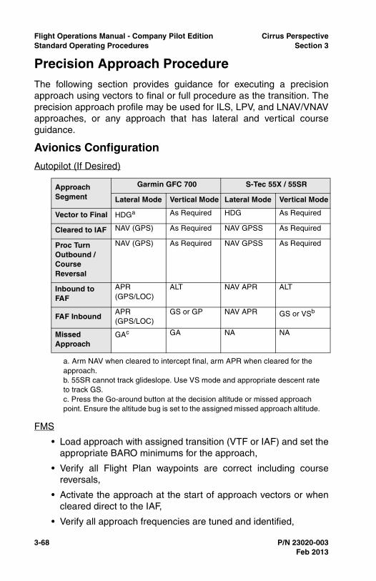
3-68 P/N 23020-003
Flight Operations Manual - Company Pilot Edition Cirrus PerspectiveStandard Operating Procedures Section 3
Precision Approach ProcedureThe following section provides guidance for executing a precisionapproach using vectors to final or full procedure as the transition. Theprecision approach profile may be used for ILS, LPV, and LNAV/VNAVapproaches, or any approach that has lateral and vertical courseguidance.
Avionics Configuration
Autopilot (If Desired)
FMS
• Load approach with assigned transition (VTF or IAF) and set theappropriate BARO minimums for the approach,
• Verify all Flight Plan waypoints are correct including coursereversals,
• Activate the approach at the start of approach vectors or whencleared direct to the IAF,
• Verify all approach frequencies are tuned and identified,
Approach Segment
Garmin GFC 700 S-Tec 55X / 55SR
Lateral Mode Vertical Mode Lateral Mode Vertical Mode
Vector to Final HDGa
a. Arm NAV when cleared to intercept final, arm APR when cleared for the approach.
As Required HDG As Required
Cleared to IAF NAV (GPS) As Required NAV GPSS As Required
Proc Turn Outbound / Course Reversal
NAV (GPS) As Required NAV GPSS As Required
Inbound to FAF
APR (GPS/LOC)
ALT NAV APR ALT
FAF InboundAPR (GPS/LOC)
GS or GP NAV APR GS or VSb
b. 55SR cannot track glideslope. Use VS mode and appropriate descent rate to track GS.
Missed Approach
GAc
c. Press the Go-around button at the decision altitude or missed approach point. Ensure the altitude bug is set to the assigned missed approach altitude.
GA NA NA
Feb 2013
Cirrus Perspective Flight Operations Manual - Company Pilot EditionSection 3 Standard Operating Procedures
P/N 23020-003 3-69
• Verify the navigation mode switches from GPS to LOC on an ILSapproach when inbound to FAF.
MFD
• Reference charts for approach information and briefing,
• Reference the electronic checklist at the completion of theDescent and Before Landing flows.
PFD
• Set the Altitude bug for the Missed Approach Altitude (DA withS-Tec AP) once established inbound to FAF,
• Sync the HDG bug for the wind correction heading onceestablished inbound on the final approach course.
Completion Standards
• Complies with all ATC clearances, instructions, and proceduresin a timely manner,
• Establishes aircraft configuration and airspeed asrecommended in this manual,
• Completes the Descent and Before Landing checklists prior tothe FAF,
• Completes an approach briefing before becoming establishedon a published segment of the approach,
• Before the FAF, maintains altitude +/-100 feet, airspeed +/-10KIAS, headings within +/-10 degrees, and accurately tracksradials, courses, and bearings,
• Completes all avionics related tasks correctly and at the propertime based upon ATC clearances,
• Maintains a stabilized final approach, from the FAF to DAallowing no more than three-quarter-scale deflection of eitherlocalizer or glideslope and maintains airspeed +/-10 KIAS,
• Promptly initiates a missed approach from the DH if requiredvisual references for the runway are not unmistakably visible,
• Transitions to a normal landing considering all regulatoryrequirements to descend below a DA,
• Maintains localizer and glideslope deviations within three-quarter-scale deflections during visual descent until glide-slopesignal must be abandoned to accomplish a normal landing.
Feb 2013
3-70 P/N 23020-003
Flight Operations Manual - Company Pilot Edition Cirrus PerspectiveStandard Operating Procedures Section 3
Common Errors
• Fails to slow the aircraft to provide adequate time for approachpreparation,
• Fails to configure the aircraft as recommended in this section,
• Exhibits improper airspeed management during level-off or startof descents during the approach,
• Neglects to verify that the autopilot is active and armed modes,
• Fails to activate the approach in the flight plan at the propertime,
• Fails to brief missed approach procedures.
Feb 2013
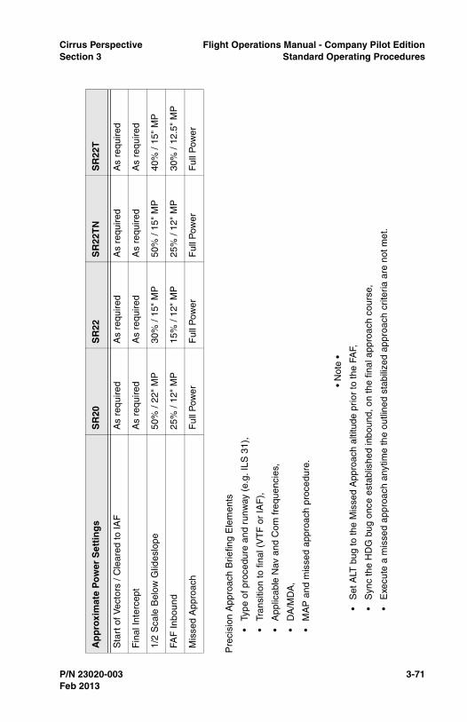
Cirrus Perspective Flight Operations Manual - Company Pilot EditionSection 3 Standard Operating Procedures
P/N 23020-003 3-71
Pre
cisi
on A
ppro
ach
Brie
fing
Ele
men
ts
•Ty
pe o
f pro
cedu
re a
nd r
unw
ay (
e.g.
ILS
31)
,
•Tr
ansi
tion
to fi
nal (
VT
F o
r IA
F),
•A
pplic
able
Nav
and
Com
freq
uenc
ies,
•D
A/M
DA
,
•M
AP
and
mis
sed
appr
oach
pro
cedu
re.
• N
ote
•
•S
et A
LT b
ug to
the
Mis
sed
App
roac
h al
titud
e pr
ior
to th
e FA
F,
•S
ync
the
HD
G b
ug o
nce
esta
blis
hed
inbo
und,
on
the
final
app
roac
h co
urse
,
•E
xecu
te a
mis
sed
appr
oach
any
time
the
outli
ned
stab
ilize
d ap
proa
ch c
riter
ia a
re n
ot m
et.
Ap
pro
xim
ate
Po
wer
Set
tin
gs
SR
20S
R22
SR
22T
NS
R22
T
Sta
rt o
f Vec
tors
/ C
lear
ed to
IAF
As
requ
ired
As
requ
ired
As
requ
ired
As
requ
ired
Fin
al In
terc
ept
As
requ
ired
As
requ
ired
As
requ
ired
As
requ
ired
1/2
Sca
le B
elow
Glid
eslo
pe50
% /
22"
MP
30%
/ 15
" M
P50
% /
15"
MP
40%
/ 15
" M
P
FAF
Inbo
und
25%
/ 12
" M
P15
% /
12"
MP
25%
/ 12
" M
P30
% /
12.5
" M
P
Mis
sed
App
roac
hF
ull P
ower
Ful
l Pow
erF
ull P
ower
Ful
l Pow
er
Feb 2013
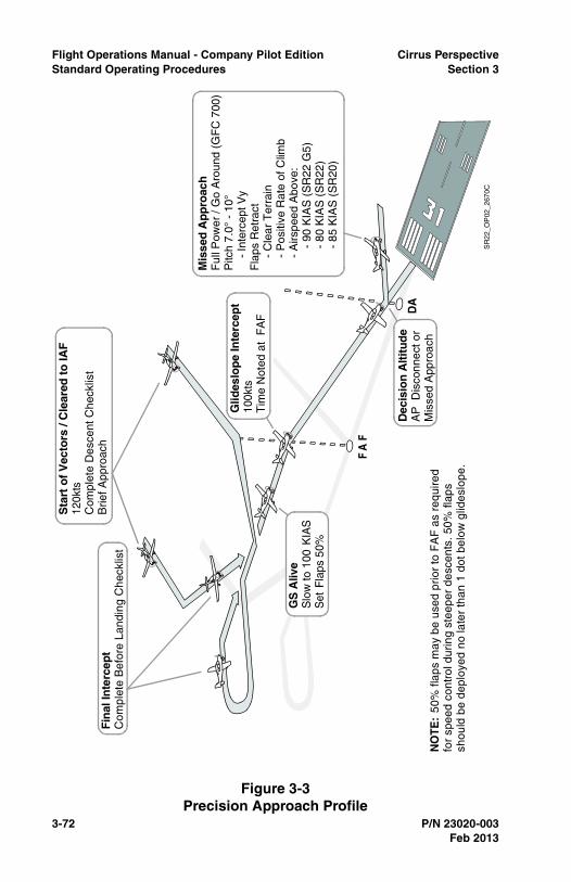
3-72 P/N 23020-003
Flight Operations Manual - Company Pilot Edition Cirrus PerspectiveStandard Operating Procedures Section 3
Figure 3-3Precision Approach Profile
NO
TE:
50%
flap
s m
ay b
e us
ed p
rior
to F
AF
as
requ
ired
for
spee
d co
ntro
l dur
ing
stee
per
desc
ents
. 50%
flap
ssh
ould
be
depl
oyed
no
late
r th
an 1
dot
bel
ow g
lides
lope
.
DA
FA
F
Dec
isio
n A
ltit
ud
eA
P D
isco
nnec
t or
Mis
sed
App
roac
h
Sta
rt o
f V
ecto
rs /
Cle
ared
to
IAF
120k
tsC
ompl
ete
Des
cent
Che
cklis
tB
rief A
ppro
ach
Glid
eslo
pe
Inte
rcep
t10
0kts
Tim
e N
oted
at
FA
F
GS
Aliv
eS
low
to 1
00 K
IAS
Set
Fla
ps 5
0%
Mis
sed
Ap
pro
ach
Ful
l Pow
er /
Go
Aro
und
(GF
C 7
00)
Pitc
h 7.
0° -
10°
-
Inte
rcep
t Vy
Fla
ps R
etra
ct
- C
lear
Ter
rain
-
Pos
itive
Rat
e of
Clim
b
- A
irspe
ed A
bove
:
-
90
KIA
S (
SR
22 G
5)
-
80
KIA
S (
SR
22)
- 8
5 K
IAS
(S
R20
)
Fin
al In
terc
ept
Com
plet
e B
efor
e La
ndin
g C
heck
list
SR
22_O
P02
_267
0C
Feb 2013

Cirrus Perspective Flight Operations Manual - Company Pilot EditionSection 3 Standard Operating Procedures
P/N 23020-003 3-73
Nonprecision Approach ProcedureThe following provides guidance for executing a nonprecisionapproach with no vertical guidance using vectors to final or fullprocedure as the transition. The nonprecision profile may be used forVOR, Localizer, Localizer Back Course, GPS, or any approach thatonly has lateral course guidance.
Avionics Configuration
Autopilot (If Desired)
FMS
• Load approach with assigned transition (VTF or IAF) and setappropriate BARO minimums for the approach,
• Verify all Flight Plan waypoints are correct including coursereversals,
• Activate the approach at the start of approach vectors or whencleared direct to the IAF,
• Verify all approach frequencies are tuned and identified,
Approach Segment
Garmin GFC 700 S-Tec 55X / 55SR
Lateral ModeVertical Mode
Lateral ModeVertical Mode
Vector to Final HDGa
a. Arm NAV when cleared to intercept final, arm APR when cleared for the approach.
As Required HDG As Required
Cleared to IAF NAV (GPS) As Required NAV GPSS As Required
Proc Turn Outbound / Course Reversal
NAV (GPS) As Required NAV GPSS As Required
Inbound to FAF
NAV (GPS, VOR, LOC, BC)
ALT GPSS (GPS)APR (VOR/LOC)
ALT
FAF InboundAPR (GPS, VOR, LOC, BC)
VS + ALTS GPSS (GPS)APR (VOR/LOC)
VS +ALT
Missed Approach
GAb
b. Press the Go-around button at the decision altitude or missed approach point. Ensure the altitude bug is set to the assigned missed approach altitude.
GA NA NA
Feb 2013
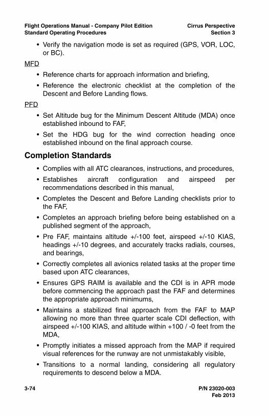
3-74 P/N 23020-003
Flight Operations Manual - Company Pilot Edition Cirrus PerspectiveStandard Operating Procedures Section 3
• Verify the navigation mode is set as required (GPS, VOR, LOC,or BC).
MFD
• Reference charts for approach information and briefing,
• Reference the electronic checklist at the completion of theDescent and Before Landing flows.
PFD
• Set Altitude bug for the Minimum Descent Altitude (MDA) onceestablished inbound to FAF,
• Set the HDG bug for the wind correction heading onceestablished inbound on the final approach course.
Completion Standards
• Complies with all ATC clearances, instructions, and procedures,
• Establishes aircraft configuration and airspeed perrecommendations described in this manual,
• Completes the Descent and Before Landing checklists prior tothe FAF,
• Completes an approach briefing before being established on apublished segment of the approach,
• Pre FAF, maintains altitude +/-100 feet, airspeed +/-10 KIAS,headings +/-10 degrees, and accurately tracks radials, courses,and bearings,
• Correctly completes all avionics related tasks at the proper timebased upon ATC clearances,
• Ensures GPS RAIM is available and the CDI is in APR modebefore commencing the approach past the FAF and determinesthe appropriate approach minimums,
• Maintains a stabilized final approach from the FAF to MAPallowing no more than three quarter scale CDI deflection, withairspeed +/-100 KIAS, and altitude within +100 / -0 feet from theMDA,
• Promptly initiates a missed approach from the MAP if requiredvisual references for the runway are not unmistakably visible,
• Transitions to a normal landing, considering all regulatoryrequirements to descend below a MDA.
Feb 2013
Cirrus Perspective Flight Operations Manual - Company Pilot EditionSection 3 Standard Operating Procedures
P/N 23020-003 3-75
Common Errors
• Fails to slow the aircraft to provide adequate time for approachpreparation,
• Fails to verify CDI sensitivity and RAIM,
• Fails to configure the aircraft as recommended in this section,
• Exhibits improper airspeed management during level-off or startof descents during the approach,
• Fails to verify the autopilot’s active and armed modes,
• Fails to activate the approach in the flight plan at the propertime,
• Fails to brief missed approach procedures.
Feb 2013
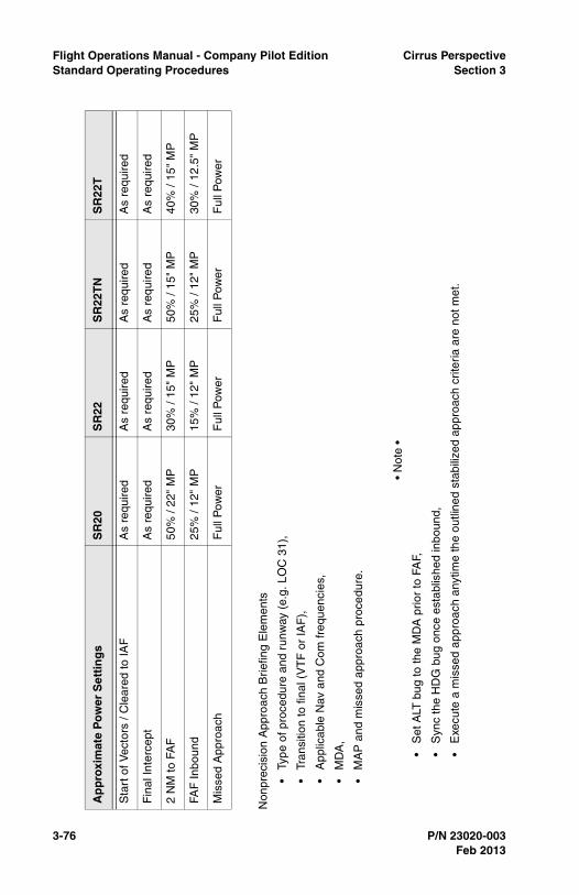
3-76 P/N 23020-003
Flight Operations Manual - Company Pilot Edition Cirrus PerspectiveStandard Operating Procedures Section 3
Non
prec
isio
n A
ppro
ach
Brie
fing
Ele
men
ts
•Ty
pe o
f pro
cedu
re a
nd r
unw
ay (
e.g.
LO
C 3
1),
•Tr
ansi
tion
to fi
nal (
VT
F o
r IA
F),
•A
pplic
able
Nav
and
Com
freq
uenc
ies,
•M
DA
,
•M
AP
and
mis
sed
appr
oach
pro
cedu
re.
• N
ote
•
•S
et A
LT b
ug to
the
MD
A p
rior
to F
AF,
•S
ync
the
HD
G b
ug o
nce
esta
blis
hed
inbo
und,
•E
xecu
te a
mis
sed
appr
oach
any
time
the
outli
ned
stab
ilize
d ap
proa
ch c
riter
ia a
re n
ot m
et.
Ap
pro
xim
ate
Po
wer
Set
tin
gs
SR
20S
R22
SR
22T
NS
R22
T
Sta
rt o
f Vec
tors
/ C
lear
ed to
IAF
As
requ
ired
As
requ
ired
As
requ
ired
As
requ
ired
Fin
al In
terc
ept
As
requ
ired
As
requ
ired
As
requ
ired
As
requ
ired
2 N
M to
FA
F50
% /
22"
MP
30%
/ 15
" M
P50
% /
15"
MP
40%
/ 15
" M
P
FAF
Inbo
und
25%
/ 12
" M
P15
% /
12"
MP
25%
/ 12
" M
P30
% /
12.5
" M
P
Mis
sed
App
roac
hF
ull P
ower
Ful
l Pow
erF
ull P
ower
Ful
l Pow
er
Feb 2013
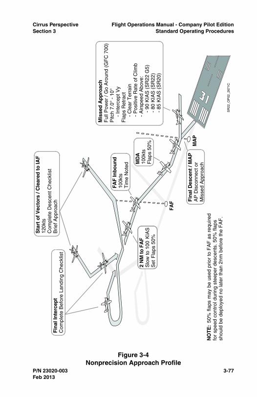
Cirrus Perspective Flight Operations Manual - Company Pilot EditionSection 3 Standard Operating Procedures
P/N 23020-003 3-77
Figure 3-4Nonprecision Approach Profile
FAF
MA
P
2 N
M t
o F
AF
Slo
w to
100
KIA
SS
et F
laps
50%
Fin
al D
esce
nt
/ MA
PA
P D
isco
nnec
t or
Mis
sed
App
roac
h
Mis
sed
Ap
pro
ach
Ful
l Pow
er /
Go
Aro
und
(GF
C 7
00)
Pitc
h 7.
0° -
10°
-
Inte
rcep
t Vy
Fla
ps R
etra
ct
- C
lear
Ter
rain
-
Pos
itive
Rat
e of
Clim
b
- A
irspe
ed A
bove
:
-
90
KIA
S (
SR
22 G
5)
-
80
KIA
S (
SR
22)
- 8
5 K
IAS
(S
R20
)
MD
A10
0kts
Fla
ps 5
0%
FAF
Inbo
und
100k
tsT
ime
Not
ed
Sta
rt o
f V
ecto
rs /
Cle
ared
to
IAF
120k
tsC
ompl
ete
Des
cent
Che
cklis
tB
rief A
ppro
ach
Fin
al In
terc
ept
Com
plet
e B
efor
e La
ndin
g C
heck
list
SR
22_O
P02
_267
1C
NO
TE:
50%
flap
s m
ay b
e us
ed p
rior
to F
AF
as
requ
ired
for
spee
d co
ntro
l dur
ing
stee
per
desc
ents
. 50%
flap
ssh
ould
be
depl
oyed
no
late
r th
an 2
nm b
efor
e th
e F
AF
.
Feb 2013
3-78 P/N 23020-003
Flight Operations Manual - Company Pilot Edition Cirrus PerspectiveStandard Operating Procedures Section 3
Go-AroundA go-around should be executed anytime an approach does not meetthe stabilized approach criteria outlined in this manual for instrumentor visual conditions. A go-around should be completed from memorysince it is a time critical maneuver.
In addition to the stabilized approach criteria, execute a go-around/missed approach for these conditions:
• Excessive ballooning during round-out or flare,
• Excessive bouncing or porpoising,
• Landing beyond the first third of the runway,
• Any condition when a safe landing is in question.
The first priority of executing a go-around is to stop the aircraft’sdescent. Smoothly and promptly apply full power while simultaneouslyleveling the wings and pitching the aircraft to stop the descent.Maintain coordination while adding power by applying rudderpressure. Retract the flaps to 50%. Do not fully retract the flaps at thispoint in the go-around because it may lead to excessive altitude loss.
Begin pitching for a climb attitude once the aircraft's descent rate hasbeen stopped and the aircraft is accelerating. Pitch for VX if obstacleclearance is an issue. Pitch for VY for all other situations. Retract flapsto 0% once the aircraft is climbing, clear of obstacles, and above 80KIAS (SR22), 85 KIAS (SR20), or 90 KIAS (SR22 G5).
Procedure (Memory)
1. Autopilot .....................................................................DISENGAGE
GFC 700 - Disengage the autopilot by pressing the go-aroundbutton located on the throttle. The yaw damper will remainengaged after pressing the go-around button.
• Note •
Press the go-around button on the throttle handle whenexecuting a missed approach from an IAP for aircraftequipped with the GFC 700 autopilot.
S-Tec 55X/SR - Disengaged the Autopilot by pressing the APDISC on the control yoke.
2. Power Lever ........................................................FULL FORWARD
Feb 2013
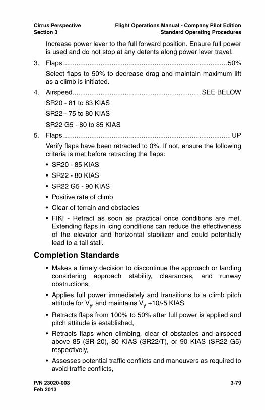
Cirrus Perspective Flight Operations Manual - Company Pilot EditionSection 3 Standard Operating Procedures
P/N 23020-003 3-79
Increase power lever to the full forward position. Ensure full poweris used and do not stop at any detents along power lever travel.
3. Flaps ........................................................................................50%
Select flaps to 50% to decrease drag and maintain maximum liftas a climb is initiated.
4. Airspeed..................................................................... SEE BELOW
SR20 - 81 to 83 KIAS
SR22 - 75 to 80 KIAS
SR22 G5 - 80 to 85 KIAS
5. Flaps .......................................................................................... UP
Verify flaps have been retracted to 0%. If not, ensure the followingcriteria is met before retracting the flaps:
• SR20 - 85 KIAS
• SR22 - 80 KIAS
• SR22 G5 - 90 KIAS
• Positive rate of climb
• Clear of terrain and obstacles
• FIKI - Retract as soon as practical once conditions are met.Extending flaps in icing conditions can reduce the effectivenessof the elevator and horizontal stabilizer and could potentiallylead to a tail stall.
Completion Standards
• Makes a timely decision to discontinue the approach or landingconsidering approach stability, clearances, and runwayobstructions,
• Applies full power immediately and transitions to a climb pitchattitude for Vy, and maintains Vy +10/-5 KIAS,
• Retracts flaps from 100% to 50% after full power is applied andpitch attitude is established,
• Retracts flaps when climbing, clear of obstacles and airspeedabove 85 (SR 20), 80 KIAS (SR22/T), or 90 KIAS (SR22 G5)respectively,
• Assesses potential traffic conflicts and maneuvers as required toavoid traffic conflicts,
Feb 2013
3-80 P/N 23020-003
Flight Operations Manual - Company Pilot Edition Cirrus PerspectiveStandard Operating Procedures Section 3
• Announces the go-around to the control tower or local trafficafter the aircraft is climbing at the desired airspeed withconfiguration set and when workload permits.
Common Errors
• Fails to recognize and initiate a go-around,
• Fails to apply full takeoff power,
• Fails to maintain coordination during a go-around,
• Neglects to disconnect the autopilot,
• Retracts flaps before adding power,
• Improper pitch control resulting in excessive loss of altitude, stallentry, or both,
• Announces go-around before regaining aircraft control,
• Fails to keep the aircraft aligned and over the runway throughoutthe go-around and initial climb.
Feb 2013
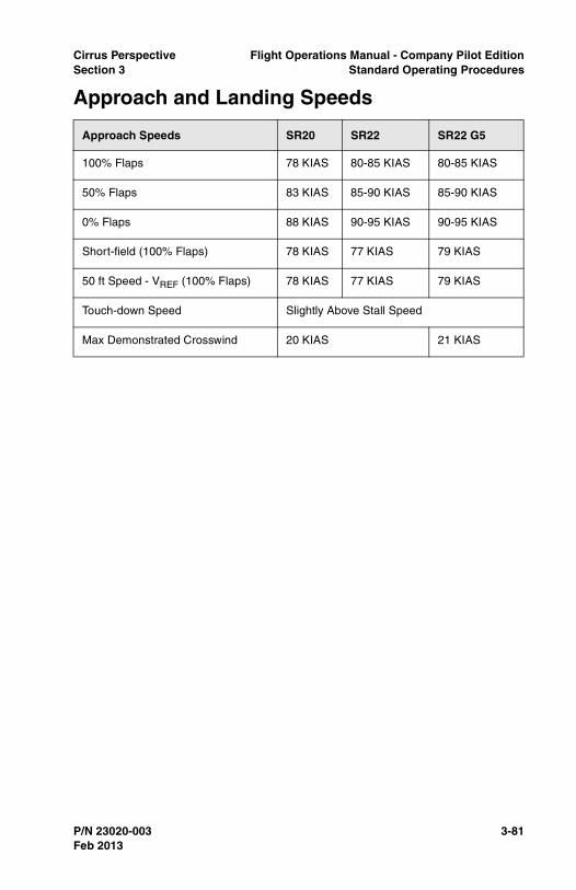
Cirrus Perspective Flight Operations Manual - Company Pilot EditionSection 3 Standard Operating Procedures
P/N 23020-003 3-81
Approach and Landing Speeds
Approach Speeds SR20 SR22 SR22 G5
100% Flaps 78 KIAS 80-85 KIAS 80-85 KIAS
50% Flaps 83 KIAS 85-90 KIAS 85-90 KIAS
0% Flaps 88 KIAS 90-95 KIAS 90-95 KIAS
Short-field (100% Flaps) 78 KIAS 77 KIAS 79 KIAS
50 ft Speed - VREF (100% Flaps) 78 KIAS 77 KIAS 79 KIAS
Touch-down Speed Slightly Above Stall Speed
Max Demonstrated Crosswind 20 KIAS 21 KIAS
Feb 2013

3-82 P/N 23020-003
Flight Operations Manual - Company Pilot Edition Cirrus PerspectiveStandard Operating Procedures Section 3
Normal LandingNormal landings should be made with 100% flaps. Final approachspeeds should be adjusted to account for gusts exceeding 10 KTS byadding half of the gust factor. Reduce power smoothly and beginslowing from the final approach speed at a time that allows an easytransition from final descent to round-out and flare with minimumfloating or ballooning. Touch-downs should be made on the mainwheels first at speeds slightly above stall. Gently lower the nose wheelafter the mains are on the ground.
Completion Standards
• Considers the wind conditions, landing surface, obstructions,and selects a suitable touch-down point within the first 1/3 of therunway,
• Establishes the aircraft approach and landing configuration andairspeed as recommended, and adjusts pitch and power asrequired,
• Maintains a stabilized approach and recommended airspeed +/-5 KIAS with wind gust factor applied,
• Manages airspeed and power to minimize floating during round-out,
• Touches down smoothly at approximate stalling speed,
• Touches down at or within 400 feet beyond a specified point,with no drift, and with the airplane’s longitudinal axis alignedwith and over the runway centerline,
• Maintains crosswind correction and directional controlthroughout the approach and landing sequence,
• Completes the Before Landing checklist,
• Uses brakes as required while maintaining directional control.Keeps the runway centerline between the main landing gearuntil reaching the desired turnoff point,
Common Errors
• Flares too high creating a stall to hard landing situation,
• Touches down 5 to 10 KIAS above stall speed causing a flatlanding attitude and possible pilot-induced oscillation,
Feb 2013
Cirrus Perspective Flight Operations Manual - Company Pilot EditionSection 3 Standard Operating Procedures
P/N 23020-003 3-83
• Fails to keep the aircraft on the centerline throughout the landingroll,
• Fails to initiate a go-around for unsafe landing situations,
• Fails to continuously add back pressure to slow the aircraftduring round-out into the flare,
• Relaxes elevator back pressure during flare to quickly aftertouch-down.
Feb 2013
3-84 P/N 23020-003
Flight Operations Manual - Company Pilot Edition Cirrus PerspectiveStandard Operating Procedures Section 3
Short-Field LandingLandings on short runways should be made with 100% flaps. Finalapproach speeds should be adjusted to account for wind gustsexceeding 10 KIAS by adding half the gust factor. Progressivelyreduce power after clearing all approach obstacles. Proper airspeedand power control should result in an approach with minimal floating inground effect without excessive sink rates during the approach. Touch-down should be made on the main wheels first. Immediately aftertouch-down, ensure power is at idle, lower the nose wheel and applybrakes as required. To decrease stopping distances, considerretracting the flaps and holding the control yoke full aft. Emphasisshould be placed on the accuracy of the touch-down to ensure enoughrunway remains after touch-down to stop the aircraft.
Completion Standards
• Adheres to applicable completion standards for normal landings,
• Touches down at or within 200 feet beyond a specified point,with no side drift, minimum float and with the airplane’slongitudinal axis aligned with and over the runway center,
• Applies brakes and elevator control as necessary to stop in theshortest distance consistent with safety,
• Executes a go-around if sufficient runway for braking is notavailable.
Common Errors
• Selects and tracks to an aiming point that results in a touch-down beyond the desired landing point,
• Touches down before the specified touch-down point,
• Touches down 200 feet beyond the specified touch-down point,
• Fails to adjust approach angle to compensate for obstacles ifapplicable,
• Fails to recognize the need for a slip to landing for obstacleclearance purposes,
• Fails to adjust airspeed to the recommended short-fieldapproach speed,
• Applies excessive braking causing undue brake wear or loss ofdirectional control.
Feb 2013
Cirrus Perspective Flight Operations Manual - Company Pilot EditionSection 3 Standard Operating Procedures
P/N 23020-003 3-85
Soft-Field LandingCirrus aircraft are approved for landings on soft field and turf runways.Add 20% to the landing ground-roll distance when landing on a drygrass runway and 60% when landing on a wet grass runway. Alwaysensure that the quality and condition of the runway surface isadequate to support the aircraft. Avoid turf runways with long grass,wet or soggy soil, large ruts or holes. A soft field approach is quitesimilar to a normal landing approach. Touch-downs should be madeon the main wheels first. A soft touch-down will reduce the stress onthe landing gear and make it easier to keep the nose wheel fromdigging into the turf preventing a loss of directional control. Keep thenose wheel off the ground as long as possible by applying sufficientback pressure to the control yoke. A little power can be addedimmediately after touch-down to aid in keeping the nose wheel off theground. Braking should be minimized. Excessive braking could lead toa loss of directional control on the runway. Higher power settings willbe required to taxi on a soft field.
Completion Standards
• Adheres to applicable completion standards for normal andshort-field landings,
• Touches down smoothly on the main landing gear and holds fullelevator aft controls throughout the landing roll and taxi,
• Applies brakes only as required and maintains directionalcontrol without locking the brakes during the landing roll.
Common Errors
• Fails to accurately assess height above touch-down resulting ina flat, hard, or unsafe touch-down,
• Fails to touch-down accurately resulting in a runway over runsituation,
• Fails to hold full elevator back pressure to reduce nose wheelpressure/fatigue,
• Fails to assess runway condition before attempting takeoff orlanding,
• Fails to account for sunrise or sunset times when planning aflight out of, or into an unlit soft field runway.
Feb 2013
3-86 P/N 23020-003
Flight Operations Manual - Company Pilot Edition Cirrus PerspectiveStandard Operating Procedures Section 3
Crosswind LandingCrosswind landings should be made with 100% flaps. It isrecommended to crab the aircraft into the wind sufficiently enough totrack the aircraft along the extended centerline of the runway. Hold thecrab until the beginning of the round-out. At the start of the round-out,enter a slip by applying rudder pressure to align the longitudinal axis ofthe aircraft with the runway and simultaneously apply aileron to keepthe aircraft tracking the runway centerline. Touch-downs should bemade on the upwind main landing gear first, followed by the downwindmain landing gear, and nose gear. Hold aileron correction into the windduring the rollout and apply rudder as necessary to maintaindirectional control.
Completion Standards
• Adheres to applicable completion standards for normal, short-field, and soft field landings,
• Identifies need for crosswind technique,
• Smoothly applies rudder and aileron inputs to align thelongitudinal axis of the aircraft with the runway over the runwaycenterline with no drift as the aircraft enters the round-out phaseof landing,
• Holds aileron crosswind control inputs after touch-down andthrough the landing roll,
• Identifies crosswind conditions that exceed the pilot’scapabilities and develops alternative plans for safe landing,
• Selects 100% flaps.
Common Errors
• Applying excessive control inputs resulting in uncoordinatedflight,
• Fails to hold ailerons into the wind after touch-down with no drift,
• Touches down with drift,
• Fails to recognize an unsafe crosswind situation and fails toselect a more suitable landing runway,
• Develops marginal crosswind proficiency on a long and widerunway. Pilot then assumes he or she will be proficient onshorter and narrower runways.
Feb 2013
Cirrus Perspective Flight Operations Manual - Company Pilot EditionSection 3 Standard Operating Procedures
P/N 23020-003 3-87
Reduced Flap Landings (0% and 50%)While most landings in Cirrus aircraft are performed with 100% flaps, itis important for pilots to develop proficiency landing with 50% or 0%flaps. Landing with less than 100% flaps should be considered a non-typical situation requiring a heightened sense of awareness andcaution. Final approach speeds are increased by 5 KIAS for 50% flapand 10 KIAS for 0% flap landings due to the increased stall speed withreduced flap deflection. A slightly larger traffic pattern will be requiredto descend the aircraft on an approximately 3 degree glidepath to therunway without excessively high descent rates.
Pilots must also be aware that the aircraft will be at a higher angle ofattack as compared to a landing with full flaps on final approach andduring touch-down. Pilots are cautioned to not exceed 10 degrees ofnose high pitch during the round-out and flare to prevent a tail strike.Landing distances with reduced flaps will be greater due to increasedfinal approach and touch-down speeds.
Pilots landing from an instrument approach procedure may elect toland with approach flaps (50%) if changing flap configuration on shortfinal will create an unstabilized approach. Increase final approachspeed and ensure adequate runway remains for safe stopping.
Completion Standards
• Adheres to applicable completion standards for normal, short-field, and/or crosswind landings,
• Selects a runway with adequate distance,
• Adjusts final approach speed as required,
• Adjusts traffic pattern as necessary for a stabilized approach,
• Does not flare the aircraft excessively during round-out andflare.
Common Errors
• Fails to select a runway with adequate distance,
• Overshoots desired touch-down point excessively,
• Over rotates the aircraft during round-out or flare,
• Fails to adjust traffic pattern for reduced flap landing,
• Elects to land with 50% flaps in crosswind conditions whennormal procedure calls for 100%.
Feb 2013

3-88 P/N 23020-003
Flight Operations Manual - Company Pilot Edition Cirrus PerspectiveStandard Operating Procedures Section 3
Icing Landing Procedure1. ICE PROTECT System Switch................................................... On
It is important to ensure the switch has been set to the intendedposition. This is especially true for night operations.
2. ICE PROTECT Mode Switch........................... HIGH / As Required
HIGH should be selected initially. If ice accumulation rate is low,select NORM. If ice does not shed, select MAX and perform theAnti-ice System Failure checklist.
3. WIND SHLD Push-Button .................................Press As Required
Use the windshield ice protection when residual fluid that is slungfrom the propeller will not keep the windshield free of ice.
• Caution •
To prevent an obstructed view due to residual anti-ice fluid onwindshield, do not operate windshield ice system within 30seconds of landing.
4. Ice Inspection Lights ................................................... As Required
Ice inspection lights will illuminate the leading edges of the wingsand horizontal stabilizer in order to monitor ice accumulation andconfirm fluid flow at night.
5. Flaps ........................................................................................50%
Approaches and landings in icing conditions or with ice adheringto the aircraft should be made with 50% flaps. Extending flaps to100% in icing conditions can reduce the effectiveness of theelevator and horizontal stabilizer and could potentially lead to a tailstall.
6. Airspeed......................................................... Minimum of 95 KIAS
Residual ice on the protected areas and ice accumulation on theunprotected areas of the airplane can cause an increase in stallspeed even with the anti-ice system operating. Refer to the StallSpeeds with 45 Minute Ice Accumulation chart in the TKS Anti-iceSystem supplement.
7. Airspeed on Short Final .....................................................88 KIAS
Airspeed should be no less than 88 KIAS if icing conditions existor with ice adhering to the airframe due to the possibility of anincreased stall speed.
Feb 2013
Cirrus Perspective Flight Operations Manual - Company Pilot EditionSection 3 Standard Operating Procedures
P/N 23020-003 3-89
Completion Standards
• Adheres to applicable completion standards for normal andshort-field landings,
• Identifies the need, actual or simulated by the instructor, toperform the icing landing procedure,
• Selects a runway with adequate landing distance to perform theicing landing procedure considering landing distances andground roll published in the TKS Anti-Ice Supplement.
Common Errors
• Fails to identify the need for the icing landing procedure,
• Neglects to assess the landing distance performanceimplications of the icing landing procedure,
• Lands with over-rotation causing a tail strike.
Feb 2013
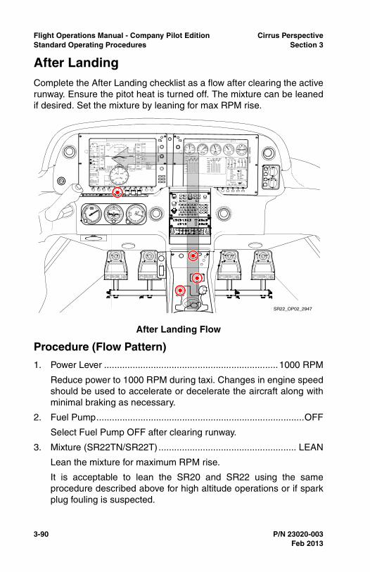
3-90 P/N 23020-003
Flight Operations Manual - Company Pilot Edition Cirrus PerspectiveStandard Operating Procedures Section 3
After Landing Complete the After Landing checklist as a flow after clearing the activerunway. Ensure the pitot heat is turned off. The mixture can be leanedif desired. Set the mixture by leaning for max RPM rise.
Procedure (Flow Pattern)
1. Power Lever ...................................................................1000 RPM
Reduce power to 1000 RPM during taxi. Changes in engine speedshould be used to accelerate or decelerate the aircraft along withminimal braking as necessary.
2. Fuel Pump................................................................................OFF
Select Fuel Pump OFF after clearing runway.
3. Mixture (SR22TN/SR22T) ..................................................... LEAN
Lean the mixture for maximum RPM rise.
It is acceptable to lean the SR20 and SR22 using the sameprocedure described above for high altitude operations or if sparkplug fouling is suspected.
After Landing Flow
SR22_OP02_2947
Feb 2013
Cirrus Perspective Flight Operations Manual - Company Pilot EditionSection 3 Standard Operating Procedures
P/N 23020-003 3-91
4. Flaps .......................................................................................... UP
Select flaps to 0% (UP) after clearing runway.
5. Transponder ...........................................................................STBY
Ensure transponder has automatically cycled to STBY. If not,select STBY manually unless directed by ATC.
6. Lights ..................................................................... AS REQUIRED
Reduce external lighting once clearing the runway to the minimumrequired for safe/legal operation so as to avoid creating a hazardto others.
7. Pitot Heat .................................................................................OFF
Select Pitot Heat OFF.
8. Ice Protection System..............................................................OFF
Select Ice Protection System OFF if used for landing.
Completion Standards
• Completes the after landing checklist procedure after clearingthe active runway,
• (FIKI) Turns pitot heat off within 45 seconds after landing.
Common Errors
• Completes checklist items during landing ground roll, beforeclearing the active runway, or during taxi,
• Neglects to complete checklist items and/or reference thechecklist after landing.
Feb 2013
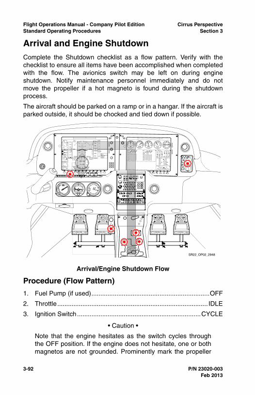
3-92 P/N 23020-003
Flight Operations Manual - Company Pilot Edition Cirrus PerspectiveStandard Operating Procedures Section 3
Arrival and Engine ShutdownComplete the Shutdown checklist as a flow pattern. Verify with thechecklist to ensure all items have been accomplished when completedwith the flow. The avionics switch may be left on during engineshutdown. Notify maintenance personnel immediately and do notmove the propeller if a hot magneto is found during the shutdownprocess.
The aircraft should be parked on a ramp or in a hangar. If the aircraft isparked outside, it should be chocked and tied down if possible.
Procedure (Flow Pattern)
1. Fuel Pump (if used)..................................................................OFF
2. Throttle .................................................................................... IDLE
3. Ignition Switch .....................................................................CYCLE
• Caution •
Note that the engine hesitates as the switch cycles throughthe OFF position. If the engine does not hesitate, one or bothmagnetos are not grounded. Prominently mark the propeller
Arrival/Engine Shutdown Flow
SR22_OP02_2948
Feb 2013
Cirrus Perspective Flight Operations Manual - Company Pilot EditionSection 3 Standard Operating Procedures
P/N 23020-003 3-93
as being HOT, and contact maintenance personnelimmediately.
4. Mixture ..............................................................................CUTOFF
Reduce mixture control to the full CUTOFF position and ensureengine stops running. If the engine continues to run with themixture at idle, ensure the boost pump is in the OFF position.
5. All Switches .............................................................................OFF
Turn off all remaining switches including the air conditioning andfan if equipped.
6. Magnetos .................................................................................OFF
Turn off magnetos and remove key.
7. ELT........................................................... TRANSMIT LIGHT OUT
After a hard landing, the ELT may be activated. If this issuspected, press the RESET button located below the circuitbreaker panel near the floor by the pilot's right ankle.
8. Chocks, Tie-downs, Pitot Cover ............................. AS REQUIRED
Set parking brake if required, chock both main wheels, use tiedowns under wings and tail if necessary. Place pitot cover andstatic covers if needed.
Completion Standards
• Completes shutdown checklist as described.
Common Errors
• Fails to reference and follow the shutdown checklist procedure,
• Fails to turn the A/C or fan to the off position,
• Fails to turn the magnetos off,
• Fails to replace the CAPS pin during post flight.
Feb 2013
3-94 P/N 23020-003
Flight Operations Manual - Company Pilot Edition Cirrus PerspectiveStandard Operating Procedures Section 3
Feb 2013
Intentionally Left Blank
Cirrus Perspective Flight Operations Manual - Company Pilot EditionSection 4 Abnormal and Emergency Procedures
P/N 23020-003 4-1
Section 4Emergency & Abnormal Procedures
GeneralSections 3 and 3A of the Pilot’s Operating Handbook provide theprocedures for handling emergency and abnormal system and/or flightconditions which, if followed, will maintain an acceptable level ofairworthiness and reduce operational risk. The guidelines described inthese sections are to be used when an emergency or abnormalcondition exists and should be considered and applied as necessary.
This section does not reference all emergency and abnormalprocedures that are described in the Pilot’s Operating Handbook.Reference this section for expanded guidelines on the selectedprocedures and cockpit flow diagrams for emergency procedurememory items.
The procedures described in this section are commonly practicedduring flight training as a means to develop and assess a pilot’ssystem and procedural knowledge and his or her ability to makecorrect decisions regarding the failure or emergency situation.Completion standards are provided for pilots and instructors whenassessing performance. Reference the Common Errors sections toanticipate typical errors made by pilots when practicing theseprocedures.
Checklist Usage for Abnormal ProceduresCompletion of abnormal procedures should be done using the do-listmethod. The appropriate checklist should be directly referred to andeach item should be completed in the order prescribed.
Checklist Usage for Emergency ProceduresEmergency checklists should be completed from memory. TheEmergency Procedures section of the POH identifies checklist itemsfor emergency procedures that must be memorized. Execution ofthese procedures is considered time critical and is done withoutreference to a checklist. The checklist should only be referencedduring an emergency if workload permits. Reference the emergencyprocedure flow patterns when practicing the completion of memoryitems.
Feb 2013

4-2 P/N 23020-003
Flight Operations Manual - Company Pilot Edition Cirrus PerspectiveAbnormal and Emergency Procedures Section 4
CAPS DeploymentThe Cirrus Airframe Parachute System (CAPS) is a unique safetyfeature installed in all Cirrus aircraft. CAPS provides a level ofprotection to the pilot and passengers that is not common to mostgeneral aviation aircraft today. However, for CAPS to work, it must bemanually activated by the pilot or a passenger at a safe altitude.
No minimum altitude for deployment has been set. This is because theactual altitude loss during a particular deployment depends upon theairplane’s airspeed, altitude, and attitude at deployment as well asother environmental factors. In most cases, however, the chances of asuccessful deployment increases with altitude. As a data point, altitudeloss from level flight deployments has been demonstrated at less than400 feet, (561 feet G5), and altitude loss from spin deployments hasbeen demonstrated at less than 920 feet, (1081 feet G5). Ifcircumstances permit, it is advisable to activate the CAPS at or above2,000 feet AGL.
The circumstances and decisions to use CAPS may or may not bereadily apparent. The situations when CAPS should be considered willalways be an emergency or pending emergency. The pilot mustassess the risk of continued flight considering all known factors anddetermine the likelihood of a safe outcome. Whenever the safeoutcome of a flight is in question and there is high risk of severe injuryor death, CAPS should be used.
Pilots may encounter situations that require an immediate activation ofCAPS such as: an engine failure after takeoff, mid-air collision, spin, ora loss of control in flight. CAPS must be activated quickly under thesecircumstances to preserve altitude and control airspeed withinacceptable deployment parameters. Pre-briefing these circumstancesoften will help the pilot to react quickly and activate CAPS in a timelymanner, increasing the probability of CAPS working properly. It is alsoimportant to note that CAPS has been activated by pilots at speeds inexcess of 180 knots on multiple occasions with successful outcomes.Always keep in mind the best speed to activate CAPS is below Vpd ifable.
Emergency situations in an aircraft are always stressful and pilots mayoverlook all available options for surviving the emergency. Pilots whoregularly conduct CAPS training and think about using CAPS will oftenhave a higher probability of deploying CAPS when necessary.
Feb 2013
Cirrus Perspective Flight Operations Manual - Company Pilot EditionSection 4 Abnormal and Emergency Procedures
P/N 23020-003 4-3
Performing CAPS training in a Cirrus flight training device or simulatoris highly recommended. Visit www.cirrusaircraft.com to find aninteractive map displaying Cirrus Simulator Centers. It is alsorecommended that frequent flying passengers complete CAPStraining in a Cirrus simulator to develop the ability to properly activateCAPS.
Feb 2013
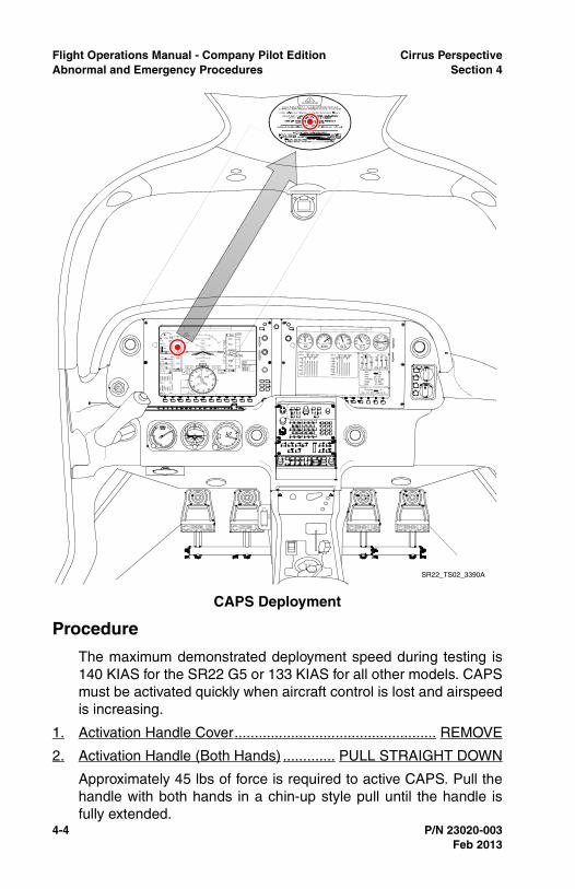
4-4 P/N 23020-003
Flight Operations Manual - Company Pilot Edition Cirrus PerspectiveAbnormal and Emergency Procedures Section 4
Procedure
The maximum demonstrated deployment speed during testing is140 KIAS for the SR22 G5 or 133 KIAS for all other models. CAPSmust be activated quickly when aircraft control is lost and airspeedis increasing.
1. Activation Handle Cover.................................................. REMOVE
2. Activation Handle (Both Hands) ............. PULL STRAIGHT DOWN
Approximately 45 lbs of force is required to active CAPS. Pull thehandle with both hands in a chin-up style pull until the handle isfully extended.
CAPS Deployment
SR22_TS02_3390A
Feb 2013

Cirrus Perspective Flight Operations Manual - Company Pilot EditionSection 4 Abnormal and Emergency Procedures
P/N 23020-003 4-5
After Deployment:
3. Mixture ............................................................................. CUTOFF
4. Fuel Selector............................................................................OFF
5. Bat-Alt Master Switches...........................................................OFF
If time permits, declare the emergency and announce CAPSactivation prior to turning off the Bat and Alt switches.
6. Ignition Switch..........................................................................OFF
7. Fuel Pump ...............................................................................OFF
8. ELT.............................................................................................ON
9. Seat Belts and Harnesses .............................................. TIGHTEN
10. Loose Items ..................................................................... SECURE
11. Assume emergency landing body position.
Reference the passenger briefing card for the correct emergencylanding body position. Be mindful of airbag seat belts if installed.
12. After the airplane comes to a complete stop, evacuate quickly andmove upwind.
In high winds the parachute may inflate and drag the aircraft aftertouchdown. Remain upwind of the aircraft.
Completion Standards
• Maintains situational awareness during the scenario and makesappropriate decisions,
• Recognizes the need to use CAPS by an appropriate altitude,
• If not in a loss of control situation, and if time and altitudepermits, slows the airplane below Vpd
• If in a loss of control situation immediately uses CAPS,
• Simulates the recommended procedure for pulling CAPS,
• Simulates the post deployment procedures time permitting andsecures the cabin,
• Identified the correct emergency landing body position,
• Recognized the most appropriate door position duringtouchdown considering outside factors.
Common Errors
• Fails to maintain situational awareness during the scenario,
Feb 2013
4-6 P/N 23020-003
Flight Operations Manual - Company Pilot Edition Cirrus PerspectiveAbnormal and Emergency Procedures Section 4
• Descends below an appropriate altitude to deploy CAPS,
• Failure to slow below Vpd, when time and altitude permits,
• Failure to complete the post deployment CAPS procedures tosecure the cabin,
• Failure to assume the emergency landing body position beforeground impact.
Feb 2013
Cirrus Perspective Flight Operations Manual - Company Pilot EditionSection 4 Abnormal and Emergency Procedures
P/N 23020-003 4-7
Emergency DescentThere are multiple situations that require the use of an emergencydescent. For example, fire, medical emergency, or an O2 malfunctionare just a few. Whatever the reason, the main purpose of performingan emergency descent is to lose altitude as quickly as possible toavoid life-threatening hazards. For some scenarios, landing the aircraftat an airport or suitable off-airport landing site or deploying CAPS maybe an additional objective.
To enter an emergency descent, reduce the power to idle and lowerthe nose approximately 10 - 15 degrees to intercept VNE. Pitch theaircraft to VNO if significant turbulence is expected during the descent.
Banking the aircraft to 45 degrees will help the aircraft accelerate morequickly as well as keep loading positive during the maneuver. It isrecommended to bank the aircraft to 45 degrees until heading 90degrees from the previous heading. From there, adjust heading asnecessary for terrain, traffic, and/or a diversion airport.
Set the mixture control as recommended below and turn the boostpump on. Clear the engine every 1000 feet by increasing MP to 15inches, then reducing back to idle. The combination of high airspeedand low power will cause CHTs to cool. It is good practice to allow theengine to warm before applying high power settings. When possiblerestore power to minimum necessary for level flight until CHTs returnto green.
Inform ATC of the emergency and intended actions and request anyassistance if necessary when workload permits.
Procedure
1. Power Lever ............................................................................ IDLE
2. Mixture ...................................................................AS REQUIRED,
• SR20 - full rich,
• SR22 - top of green fuel flow arc,
• SR22TN - full rich,
• SR22T - full rich.
3. Airspeed....................................................................................VNE
Decrease pitch to 10 - 15 degrees to intercept VNE. Maintain VNOif turbulence is expected.
Feb 2013
4-8 P/N 23020-003
Flight Operations Manual - Company Pilot Edition Cirrus PerspectiveAbnormal and Emergency Procedures Section 4
Completion Standards
• Promptly recognizes the need for an emergency descent andenters the maneuver,
• Banks aircraft to 45 degrees during the start of the maneuver toload the aircraft and increase descent rate,
• Maintains airspeed +0/-5 KIAS of target airspeed for maneuver,
• Determines the best course of action considering the nature ofthe emergency.
Common Errors
• Fails to reduce pitch sufficiently to accelerate to the desiredairspeed,
• Overspeeds the aircraft beyond VNE,
• Fails to manage airspeed and altitude properly to execute astabilized approach to landing,
• Fails to consider deploying CAPS at an appropriate altitude.
Feb 2013
Cirrus Perspective Flight Operations Manual - Company Pilot EditionSection 4 Abnormal and Emergency Procedures
P/N 23020-003 4-9
Engine Malfunctions OverviewProper pre-flight inspections, operating as per AFM recommendations,and routine maintenance all reduce the likelihood of an in-flight enginemalfunction. Although engine malfunctions are a rare occurrence,pilots must be capable of properly identifying and troubleshootingwhile maintaining aircraft control.
Pilots are encouraged to actively scan engine instrumentation duringflight to preemptively fend off or identify up and coming failures. Payclose attention to oil pressure and CHT status and trends.
Most engine malfunctions should be treated as emergencies. Pilotsshould be familiar with emergency procedure memory items and becapable of completing memory items in a timely fashion. Practicecompleting emergency procedure memory items during recurrenttraining and while sitting stationary in the aircraft.
Training Limitations
• Simulated engine failures on takeoff and power-off return toairport during departure / climb maneuvers are not permitted,
• Simulated engine failures are not permitted in actual IMC orwhen VMC cannot be maintained,
• Ensure the aircraft is in a position to make an airport landing orlanding at a suitable off-airport site when conducting thesemaneuvers in case a real emergency is encountered during thesimulated emergency practice.
Feb 2013
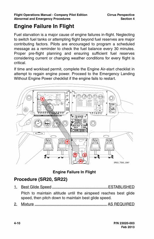
4-10 P/N 23020-003
Flight Operations Manual - Company Pilot Edition Cirrus PerspectiveAbnormal and Emergency Procedures Section 4
Engine Failure In FlightFuel starvation is a major cause of engine failures in-flight. Neglectingto switch fuel tanks or attempting flight beyond fuel reserves are majorcontributing factors. Pilots are encouraged to program a scheduledmessage as a reminder to check the fuel balance every 30 minutes.Proper pre-flight planning and ensuring sufficient fuel reservesconsidering current or changing weather conditions for every flight iscritical.
If time and workload permit, complete the Engine Air-start checklist inattempt to regain engine power. Proceed to the Emergency LandingWithout Engine Power checklist if the engine fails to restart.
Procedure (SR20, SR22)
1. Best Glide Speed ....................................................ESTABLISHED
Pitch to maintain altitude until the airspeed reaches best glidespeed, then pitch down to maintain best glide speed.
2. Mixture ................................................................... AS REQUIRED
Engine Failure In Flight
SR22_TS02_3387
Feb 2013
Cirrus Perspective Flight Operations Manual - Company Pilot EditionSection 4 Abnormal and Emergency Procedures
P/N 23020-003 4-11
Lean or enrichen the mixture in effort to supply the engine with acombustible fuel-air ratio. Use a smooth but prompt sweepingmotion to re-initiate combustion.
3. Fuel Selector........................................................ SWITCH TANKS
The engine should start shortly after switching fuel tanks if thecause of the engine failure was due to fuel starvation. Be mindfulof maximum fuel imbalances and fuel reserves required tocomplete the flight.
4. Fuel Pump ......................................................................... BOOST
Turning the boost pump on will help suppress vapors that may bein the fuel lines and/or increase fuel pressure to the injectors. Theengine will not run on the electric boost pump alone.
5. Alternate Induction Air ...............................................................ON
Press the center button on the alternate static source when pullingthe alternate induction air control knob.
6. Ignition Switch.........................................................CHECK, BOTH
Switch between the left and right magnetos. Leave the ignition onthe magneto that causes the engine to fire for the remainder of theflight.
7. If engine does not start, proceed to CAPS Deployment or ForcedLanding Checklist, as required.
Feb 2013
4-12 P/N 23020-003
Flight Operations Manual - Company Pilot Edition Cirrus PerspectiveAbnormal and Emergency Procedures Section 4
Procedure (SR22T and TN)
1. Best Glide Speed .........................................................ESTABLISH
Pitch to maintain altitude until the airspeed reaches best glidespeed, then pitch down to maintain best glide speed.
2. Fuel Selector........................................................ SWITCH TANKS
The engine should start shortly after switching fuel tanks if thecause of the engine failure was due to fuel starvation.
3. Ignition Switch ........................................................ CHECK, BOTH
Switch between the left and right magnetos. Leave the ignition onthe magneto that causes the engine to fire for the remainder of theflight.
4. Fuel Pump.......................................................................... BOOST
Turning the boost pump on will help suppress vapors that may bein the fuel lines and/or increase fuel pressure to the injectors. Theengine will not run solely on the electric boost pump if themechanical pump fails. High boost may be required above FL180for vapor suppression.
5. Power Lever ....................................................................1/2 OPEN
Set the power lever to half open before adjusting the mixturecontrol. If the engine fires, make future power changes cautiously.Return the throttle to a running position if the engine fails duringfuture throttle movements.
6. Mixture ..... IDLE CUTOFF, then slowly advance until engine starts
7. Perform Caps Deployment or Emergency Landing Without EnginePower checklist, as required.
If engine Starts:
8. CHTs and Oil Temperature ...VERIFY within GREEN range, warm engine at partial power if required
Completion Standards
• Maintains aircraft control with airspeed +/-10 KIAS of VG,
• Quickly steers the aircraft to suitable landing or CAPSdeployment area,
• Positions the aircraft to a point where a stabilized approach tolanding can be made,
Feb 2013
Cirrus Perspective Flight Operations Manual - Company Pilot EditionSection 4 Abnormal and Emergency Procedures
P/N 23020-003 4-13
• When workload permits, troubleshoots engine failure asdescribed in the AFM,
• Secures engine if engine restart is not possible before landing,
• Simulates an emergency radio call and requests ATC assistanceas necessary,
• Simulates a CAPS deployment at an appropriate altitude andairspeed, if necessary.
Common Errors
• Loses excessive altitude by not pitching to VG soon after theengine failure,
• Fails to troubleshoot failed engine as described in the AFM,
• Does not quickly determine, and steer the aircraft towards asuitable landing or CAPS deployment area and/or decide todeploy CAPS, if warranted, with adequate altitude,
• Overshoots or undershoots intended touchdown point,
• Fails to manage glide angle with flaps and/or side slip asnecessary,
• Fails to simulate declaring an emergency and getting priorityhandling and assistance from ATC,
• Fails to consider surface winds when selecting landing direction.
Feb 2013
4-14 P/N 23020-003
Flight Operations Manual - Company Pilot Edition Cirrus PerspectiveAbnormal and Emergency Procedures Section 4
Emergency Landing Without Engine PowerThe purposes of completing the Emergency Landing Without EnginePower checklist items are to secure the engine in an effort to reducefire potential after touchdown and to alert ATC of the emergencysituation through communication, transponder code, and ELT.
Turn the aircraft and glide towards an airport if available. Otherwise,glide the aircraft to the best location for CAPS deployment consideringwater, terrain, population density, etc. The flight path indicator onPerspective can be a useful tool to determine if the aircraft is capableof gliding to the intended airport. Monitor the flight path indicator whenthe aircraft is established and stabilized at best glide speed. If the flightpath indicator points beyond the airport depicted on synthetic vision, aglide to the airport may be likely. Consider possible wind changes andthe amount of maneuvering required to line up for a runway as theaircraft descends through altitude.
When reaching 2000 feet AGL, the pilot must make the decisionwhether to continue a gliding approach to landing or to activate CAPS.In many cases, CAPS will be the best option for survival, but it must beactivated in time with sufficient altitude remaining. Do not continue anattempted landing unless landing is assured.
Maintain best glide speed with flaps at 0% until landing is assured.Use flaps to increase the descent angle when landing is assured.Eventually, flaps should be placed to 100% for touch-down. All power-off landings should be made with 100% flaps to reduce touchdownspeed and potential impact forces.
Feb 2013
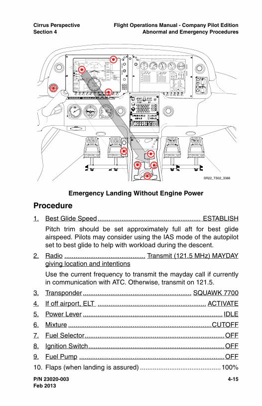
Cirrus Perspective Flight Operations Manual - Company Pilot EditionSection 4 Abnormal and Emergency Procedures
P/N 23020-003 4-15
Procedure
1. Best Glide Speed........................................................ ESTABLISH
Pitch trim should be set approximately full aft for best glideairspeed. Pilots may consider using the IAS mode of the autopilotset to best glide to help with workload during the descent.
2. Radio ............................................ Transmit (121.5 MHz) MAYDAYgiving location and intentions
Use the current frequency to transmit the mayday call if currentlyin communication with ATC. Otherwise, transmit on 121.5.
3. Transponder ........................................................... SQUAWK 7700
4. If off airport, ELT ........................................................... ACTIVATE
5. Power Lever ............................................................................ IDLE
6. Mixture ..............................................................................CUTOFF
7. Fuel Selector............................................................................OFF
8. Ignition Switch..........................................................................OFF
9. Fuel Pump ...............................................................................OFF
10. Flaps (when landing is assured) ............................................100%
Emergency Landing Without Engine Power
SR22_TS02_3388
Feb 2013
4-16 P/N 23020-003
Flight Operations Manual - Company Pilot Edition Cirrus PerspectiveAbnormal and Emergency Procedures Section 4
11. Master Switches.......................................................................OFF
12. Seat Belt(s) ................................................................... SECURED
Completion Standards
• Completes the Emergency Landing Without Engine Powerchecklist when workload permits,
• Makes a good decision whether to continue to a landing or toactivate CAPS,
• Maintains best glide speed +/-10KTS.
Common Errors
• Fails to activate CAPS at a sufficient altitude,
• Hesitates to determine, and steer the aircraft towards, an airportwithin glide range,
• Descends at an airspeed much higher than best glide, reducingglide range,
• Fails to set 100% flaps for landing or extends flaps prematurely.
Feb 2013
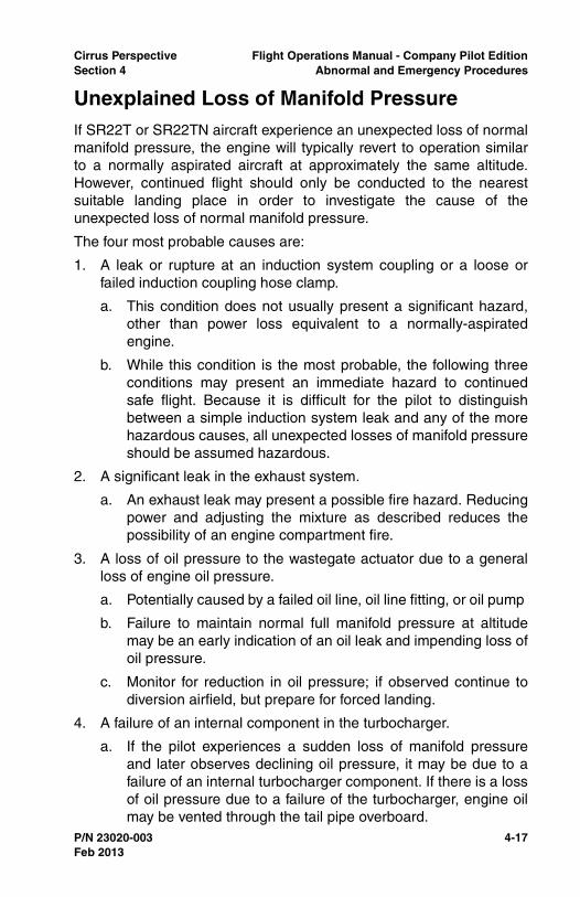
Cirrus Perspective Flight Operations Manual - Company Pilot EditionSection 4 Abnormal and Emergency Procedures
P/N 23020-003 4-17
Unexplained Loss of Manifold PressureIf SR22T or SR22TN aircraft experience an unexpected loss of normalmanifold pressure, the engine will typically revert to operation similarto a normally aspirated aircraft at approximately the same altitude.However, continued flight should only be conducted to the nearestsuitable landing place in order to investigate the cause of theunexpected loss of normal manifold pressure.
The four most probable causes are:
1. A leak or rupture at an induction system coupling or a loose orfailed induction coupling hose clamp.
a. This condition does not usually present a significant hazard,other than power loss equivalent to a normally-aspiratedengine.
b. While this condition is the most probable, the following threeconditions may present an immediate hazard to continuedsafe flight. Because it is difficult for the pilot to distinguishbetween a simple induction system leak and any of the morehazardous causes, all unexpected losses of manifold pressureshould be assumed hazardous.
2. A significant leak in the exhaust system.
a. An exhaust leak may present a possible fire hazard. Reducingpower and adjusting the mixture as described reduces thepossibility of an engine compartment fire.
3. A loss of oil pressure to the wastegate actuator due to a generalloss of engine oil pressure.
a. Potentially caused by a failed oil line, oil line fitting, or oil pump
b. Failure to maintain normal full manifold pressure at altitudemay be an early indication of an oil leak and impending loss ofoil pressure.
c. Monitor for reduction in oil pressure; if observed continue todiversion airfield, but prepare for forced landing.
4. A failure of an internal component in the turbocharger.
a. If the pilot experiences a sudden loss of manifold pressureand later observes declining oil pressure, it may be due to afailure of an internal turbocharger component. If there is a lossof oil pressure due to a failure of the turbocharger, engine oilmay be vented through the tail pipe overboard.
Feb 2013
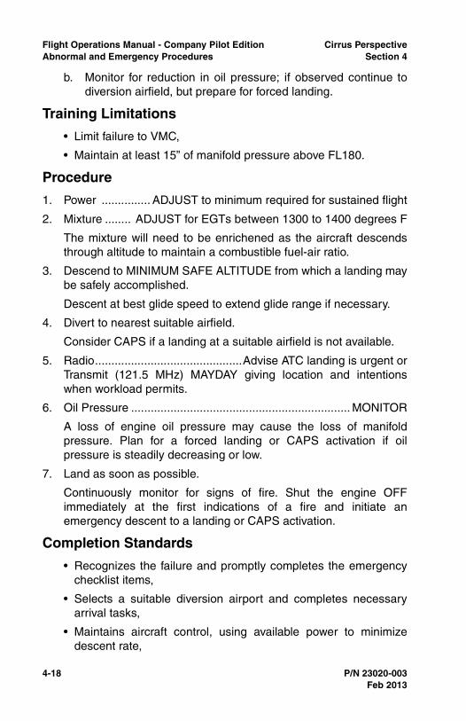
4-18 P/N 23020-003
Flight Operations Manual - Company Pilot Edition Cirrus PerspectiveAbnormal and Emergency Procedures Section 4
b. Monitor for reduction in oil pressure; if observed continue todiversion airfield, but prepare for forced landing.
Training Limitations
• Limit failure to VMC,
• Maintain at least 15” of manifold pressure above FL180.
Procedure
1. Power ............... ADJUST to minimum required for sustained flight
2. Mixture ........ ADJUST for EGTs between 1300 to 1400 degrees F
The mixture will need to be enrichened as the aircraft descendsthrough altitude to maintain a combustible fuel-air ratio.
3. Descend to MINIMUM SAFE ALTITUDE from which a landing maybe safely accomplished.
Descent at best glide speed to extend glide range if necessary.
4. Divert to nearest suitable airfield.
Consider CAPS if a landing at a suitable airfield is not available.
5. Radio.............................................Advise ATC landing is urgent orTransmit (121.5 MHz) MAYDAY giving location and intentionswhen workload permits.
6. Oil Pressure ................................................................... MONITOR
A loss of engine oil pressure may cause the loss of manifoldpressure. Plan for a forced landing or CAPS activation if oilpressure is steadily decreasing or low.
7. Land as soon as possible.
Continuously monitor for signs of fire. Shut the engine OFFimmediately at the first indications of a fire and initiate anemergency descent to a landing or CAPS activation.
Completion Standards
• Recognizes the failure and promptly completes the emergencychecklist items,
• Selects a suitable diversion airport and completes necessaryarrival tasks,
• Maintains aircraft control, using available power to minimizedescent rate,
Feb 2013
Cirrus Perspective Flight Operations Manual - Company Pilot EditionSection 4 Abnormal and Emergency Procedures
P/N 23020-003 4-19
• Monitors engine indications and describes possible indicationsof turbo or wastegate failures,
• Continuously monitors for signs of fire.
Common Errors
• Fails to describe the potential causes of the failure,
• Does not treat the failure as a potential emergency,
• Fails to land at the nearest suitable airport,
• Fails to maintain aircraft control due to the increased workload.
Feb 2013
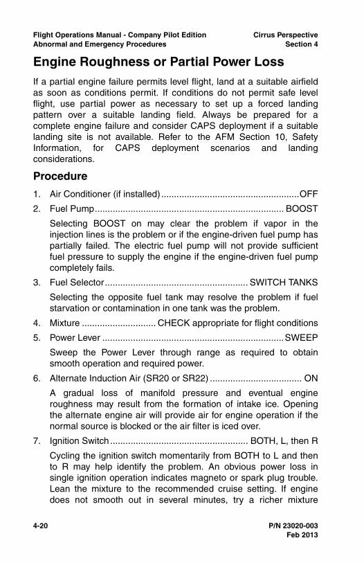
4-20 P/N 23020-003
Flight Operations Manual - Company Pilot Edition Cirrus PerspectiveAbnormal and Emergency Procedures Section 4
Engine Roughness or Partial Power LossIf a partial engine failure permits level flight, land at a suitable airfieldas soon as conditions permit. If conditions do not permit safe levelflight, use partial power as necessary to set up a forced landingpattern over a suitable landing field. Always be prepared for acomplete engine failure and consider CAPS deployment if a suitablelanding site is not available. Refer to the AFM Section 10, SafetyInformation, for CAPS deployment scenarios and landingconsiderations.
Procedure
1. Air Conditioner (if installed) ......................................................OFF
2. Fuel Pump.......................................................................... BOOST
Selecting BOOST on may clear the problem if vapor in theinjection lines is the problem or if the engine-driven fuel pump haspartially failed. The electric fuel pump will not provide sufficientfuel pressure to supply the engine if the engine-driven fuel pumpcompletely fails.
3. Fuel Selector........................................................ SWITCH TANKS
Selecting the opposite fuel tank may resolve the problem if fuelstarvation or contamination in one tank was the problem.
4. Mixture ............................. CHECK appropriate for flight conditions
5. Power Lever .......................................................................SWEEP
Sweep the Power Lever through range as required to obtainsmooth operation and required power.
6. Alternate Induction Air (SR20 or SR22) .................................... ON
A gradual loss of manifold pressure and eventual engineroughness may result from the formation of intake ice. Openingthe alternate engine air will provide air for engine operation if thenormal source is blocked or the air filter is iced over.
7. Ignition Switch ...................................................... BOTH, L, then R
Cycling the ignition switch momentarily from BOTH to L and thento R may help identify the problem. An obvious power loss insingle ignition operation indicates magneto or spark plug trouble.Lean the mixture to the recommended cruise setting. If enginedoes not smooth out in several minutes, try a richer mixture
Feb 2013
Cirrus Perspective Flight Operations Manual - Company Pilot EditionSection 4 Abnormal and Emergency Procedures
P/N 23020-003 4-21
setting. Return ignition switch to the BOTH position unlessextreme roughness dictates the use of a single magneto.
8. Land as soon as practical.
Consider the use of CAPS if a safe landing at a suitable airportcan not be guarantied.
Completion Standards
• Troubleshoots the engine roughness or partial power lossconsidering engine indications, environmental conditions, andengine control positions,
• Steers the aircraft towards a suitable landing airport,
• Maintains safe altitude until a glide to landing can be made,
• Continuously plans for an engine failure,
• Simulates declaring an emergency and receives priorityhandling and assistance from ATC if simulated conditionswarrant.
Common Errors
• Prematurely starts a descent with a partial power loss or roughengine before aircraft is within a position to glide to the airport,
• Fails to properly troubleshoot and recognize the reason forengine roughness or power loss,
• Fails to maintain aircraft control while troubleshooting engineroughness or power loss,
• Fails to contact ATC declaring an emergency and requestingpriority handling, if necessary,
• Fails to determine an appropriate landing spot or to initiate aCAPS deployment.
Feb 2013
4-22 P/N 23020-003
Flight Operations Manual - Company Pilot Edition Cirrus PerspectiveAbnormal and Emergency Procedures Section 4
Loss of Oil PressureA loss of oil pressure is an emergency situation that typically results ina catastrophic engine failure. Immediate action by the pilot is requiredto steer the aircraft towards a suitable landing or CAPS deploymentarea. Reduce power to minimum for sustained level flight to extendengine life but preserve altitude as long as possible in preparation foran engine failure.
A rise in oil temperature due to the loss of oil pressure may or may notbe seen. Do not immediately overlook a low oil pressure situation asan indication problem if oil temperature does not rise. Indicationproblems generally are identified by erratic and quick changes inpressure. A true loss of oil pressure is typically identified by a gradualand consistent decrease in pressure. Pilots are encouraged to monitoroil pressure during routine scanning to identify oil pressure issuesearly.
Procedure
1. Oil Pressure Gauge ........................................................... CHECK
High oil temperature may or may not accompany low oil pressure.
If pressure low:
a. Power....................... REDUCE to minimum for sustained flight
b. Land as soon as possible.
c. Prepare for potential engine failure.
(1) Continually select suitable forced landing fields.
(2) Prepare for CAPS activation if necessary.
Completion Standards
• Promptly investigates and determines the reason for the OILPRESS message,
• Maintains altitude until aircraft is in a position to perform apower-off approach to landing,
• Completes the emergency checklist procedure as described inthe AFM and reduces power to the minimum required for levelflight,
• Adheres to applicable performance expectations for the EngineFailure in Flight Procedure if applicable.
Feb 2013
Cirrus Perspective Flight Operations Manual - Company Pilot EditionSection 4 Abnormal and Emergency Procedures
P/N 23020-003 4-23
Common Errors
• Fails to recognize the cause of the OIL PRESS message,
• Fails to reduce power to minimum for sustained flight for a low oilpressure situation,
• Fails to recognize the severity of a low oil pressure warning,
• Fails to divert to nearest suitable airport,
• Starts descent prematurely, before the aircraft is within gliderange of a suitable runway,
• Fails to consider CAPS as an off-airport landing alternative.
Feb 2013
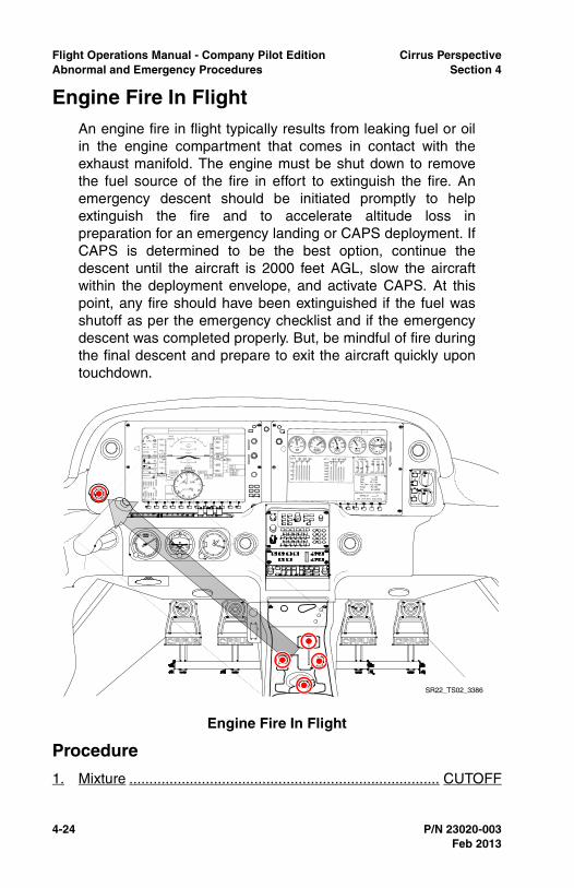
4-24 P/N 23020-003
Flight Operations Manual - Company Pilot Edition Cirrus PerspectiveAbnormal and Emergency Procedures Section 4
Engine Fire In FlightAn engine fire in flight typically results from leaking fuel or oilin the engine compartment that comes in contact with theexhaust manifold. The engine must be shut down to removethe fuel source of the fire in effort to extinguish the fire. Anemergency descent should be initiated promptly to helpextinguish the fire and to accelerate altitude loss inpreparation for an emergency landing or CAPS deployment. IfCAPS is determined to be the best option, continue thedescent until the aircraft is 2000 feet AGL, slow the aircraftwithin the deployment envelope, and activate CAPS. At thispoint, any fire should have been extinguished if the fuel wasshutoff as per the emergency checklist and if the emergencydescent was completed properly. But, be mindful of fire duringthe final descent and prepare to exit the aircraft quickly upontouchdown.
Procedure
1. Mixture ............................................................................. CUTOFF
Engine Fire In Flight
SR22_TS02_3386
Feb 2013
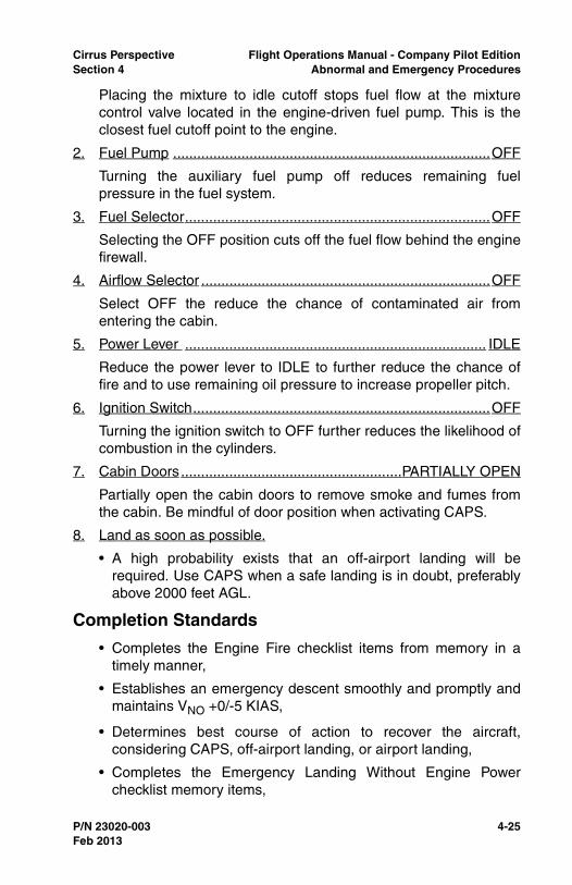
Cirrus Perspective Flight Operations Manual - Company Pilot EditionSection 4 Abnormal and Emergency Procedures
P/N 23020-003 4-25
Placing the mixture to idle cutoff stops fuel flow at the mixturecontrol valve located in the engine-driven fuel pump. This is theclosest fuel cutoff point to the engine.
2. Fuel Pump ...............................................................................OFF
Turning the auxiliary fuel pump off reduces remaining fuelpressure in the fuel system.
3. Fuel Selector............................................................................OFF
Selecting the OFF position cuts off the fuel flow behind the enginefirewall.
4. Airflow Selector ........................................................................OFF
Select OFF the reduce the chance of contaminated air fromentering the cabin.
5. Power Lever ........................................................................... IDLE
Reduce the power lever to IDLE to further reduce the chance offire and to use remaining oil pressure to increase propeller pitch.
6. Ignition Switch..........................................................................OFF
Turning the ignition switch to OFF further reduces the likelihood ofcombustion in the cylinders.
7. Cabin Doors .......................................................PARTIALLY OPEN
Partially open the cabin doors to remove smoke and fumes fromthe cabin. Be mindful of door position when activating CAPS.
8. Land as soon as possible.
• A high probability exists that an off-airport landing will berequired. Use CAPS when a safe landing is in doubt, preferablyabove 2000 feet AGL.
Completion Standards
• Completes the Engine Fire checklist items from memory in atimely manner,
• Establishes an emergency descent smoothly and promptly andmaintains VNO +0/-5 KIAS,
• Determines best course of action to recover the aircraft,considering CAPS, off-airport landing, or airport landing,
• Completes the Emergency Landing Without Engine Powerchecklist memory items,
Feb 2013

4-26 P/N 23020-003
Flight Operations Manual - Company Pilot Edition Cirrus PerspectiveAbnormal and Emergency Procedures Section 4
• Properly executes a go-around when conditions warrant.
Common Errors
• Fails to complete Engine Fire checklist memory items,
• Does not initiate emergency descent correctly and promptly ifconditions warrant,
• Fails to correctly determine whether to land at an airport, landoff-airport, or deploy CAPS.
Feb 2013
Cirrus Perspective Flight Operations Manual - Company Pilot EditionSection 4 Abnormal and Emergency Procedures
P/N 23020-003 4-27
Electrical Malfunctions OverviewCirrus aircraft are equipped with a robust, fault tolerant electricalsystem with redundant sources of power and protective devices. It isimportant for pilots to be knowledgeable of the aircraft’s powergeneration, power distribution, indicating systems, and caution andwarning systems because the aircraft’s primary flight instruments relyon electrical power for operation. During flight training, multipleelectrical failures will be simulated to develop and assess the pilot’sknowledge of the electrical system, troubleshooting techniques, anddecision making. Use the guidance in this section, coupled with theprocedures detailed in the Pilot’s Operating Handbook, when handlingtraining of electrical malfunctions.
Training Limitations
• Electrical malfunctions are not permitted in IMC or when VMCcan not be maintained,
• Limit operations to 10 minutes with alternators turned off,
• Do not turn both batteries off in flight if ATC or intercomcommunication is necessary. Energize batteries before turningalternators back on,
• Do not turn ALT 1, ALT 2, and BATT 1 off if intercomcommunication is needed or if external communication isrequired by the instructor.
• Electrical fire should only be simulated in class E or G airspaceunder VFR or simulated IFR by verbally announcing the fire.
Feb 2013

4-28 P/N 23020-003
Flight Operations Manual - Company Pilot Edition Cirrus PerspectiveAbnormal and Emergency Procedures Section 4
Alternator 1 and 2 FailuresAn alternator failure is recognized through the Crew Alerting System(CAS) on the Primary Flight Display. Pilots are encouraged to call upthe Engine page on the Multi Function Display to verify what hasfailed. Then, reference the appropriate checklist for troubleshooting.
In most cases, an alternator 1 failure is recognized by the following:
• ALT 1 caution,
• Main Bus 1 voltage at approximately 24 volts and Low M Buscaution message,
• Battery 1 discharging and associated caution message.
An alternator 2 failure is recognized by and ALT 2 caution message.No other cautions or warnings are present because alternator 1 iscapable of powering the remaining electrical equipment.
A single alternator failure is typically an abnormal condition, not anemergency procedure. Pilots are encouraged to follow checklistguidance when troubleshooting alternator issues. Reference the CASchecklist group for alternator troubleshooting guidance. The autopilotshould be engaged to decrease pilot workload during troubleshootingefforts.
Distance remaining to destination, weather, and availability ofmaintenance are factors that pilots should consider when determiningthe best course of action with a failed alternator. The Kinds ofOperation Equipment list found in section 2 of the Pilot’s OperatingHandbook allows flight to depart VFR day and night with a failedalternator 2. Alternator 1 is required for all flight dispatches. It isrecommended to land at an airport with maintenance capabilities inthe event of an alternator 1 failure to reduce aircraft down-time.
Procedure
1. ALT 1 or 2 Circuit Breaker .......................................CHECK & SET
2. ALT 1 or 2 Master Switch ....................................................CYCLE
Do not attempt multiple restarts if the failed alternator does notstart on the initial cycle. If alternator does not reset (low A1Current and M1 voltage):
3. ALT 1 or 2 Master Switch .........................................................OFF
For Alternator 1 Failures:
1. Non-Essential Bus Loads.................................................REDUCE
Feb 2013
Cirrus Perspective Flight Operations Manual - Company Pilot EditionSection 4 Abnormal and Emergency Procedures
P/N 23020-003 4-29
a. If flight conditions permit, consider shedding the following topreserve Battery 1:
(1) Air conditioning,
(2) Cabin fan,
(3) Landing light,
(4) Yaw servo,
(5) Convenience power (aux items plugged into armrest jack)
2. Continue flight, avoiding IMC or night flight as able (reduced powerredundancy).
Completion Standards
• Promptly recognizes and identifies the failure,
• Uses the autopilot to reduce workload,
• Calls up the appropriate checklist and follows checklistprocedure as a do-list,
• Makes appropriate decisions considering external factors suchas weather conditions, airspace ahead, nature of the failure,ETE to destination, etc.
Common Errors
• Completes checklist items without reference to the checklist,
• Incorrectly identifies the cause of the failure,
• Attempts multiple circuit breaker resets,
• Fails to correctly load-shed.
Feb 2013
4-30 P/N 23020-003
Flight Operations Manual - Company Pilot Edition Cirrus PerspectiveAbnormal and Emergency Procedures Section 4
Electrical Fire (Cabin Fire In Flight)An electrical fire or cabin fire in flight is an emergency situationrequiring immediate pilot action. The pilot must turn off power sourcesand electrical equipment to eliminate an electrical fire. In VFRconditions, it is recommended to turn off both batteries andalternators. Reference the magnetic compass, backup airspeedindicator, backup altimeter, and outside visual reference for aircraftcontrol.
In IMC conditions, or conditions that require flight by reference toinstruments, turn off all switches except BATT 2 to preserve power tothe primary flight display and backup attitude indicator. There is a highprobability that the source of fire will be eliminated. Turn off BATT 2 ifthe fire continues to burn. Activate CAPS if controlled flight can not bemaintained.
Procedure
1. Oxygen System (if applicable) .................................................OFF
Turn off the oxygen system, if applicable, to reduce the chance ofa severe fire in the cabin.
2. Bat-Alt Master Switches........................................ OFF, AS REQ’D
In VFR, turn off all battery and alternator switches. When flight byreference to instruments is required, leave BATT 2 ON.
3. Fire Extinguisher ............................................................ ACTIVATE
• Note •
If airflow is not sufficient to clear smoke or fumes from cabin:
4. Cabin Doors ...................................................... PARTIALLY OPEN
5. Avionics Power Switch .............................................................OFF
6. All other switches .....................................................................OFF
7. Land as soon as possible.
It is not possible to maintain aircraft control in IMC withoutelectrical power to the PFD and/or backup attitude indicator.Activate CAPS if aircraft control can not be maintained.
8. Air Conditioner (if installed) ......................................................OFF
9. Airflow Selector ........................................................................OFF
10. Bat-Alt Master Switches............................................................ ON
Feb 2013
Cirrus Perspective Flight Operations Manual - Company Pilot EditionSection 4 Abnormal and Emergency Procedures
P/N 23020-003 4-31
11. Avionics Power Switch ...............................................................ON
12. Required Systems ....................................ACTIVATE one at a time
13. Temperature Selector............................................................ COLD
14. Vent Selector......................... FEET/PANEL/DEFROST POSITION
15. Airflow Selector ...............................SET AIRFLOW TO MAXIMUM
16. Panel Eyeball Outlets............................................................OPEN
17. Land as soon as possible.
Completion Standards
• Recognizes the severity of the electrical fire and responds bycompleting the Cabin Fire in Flight checklist procedures,
• Takes appropriate action to eliminate cabin smoke and fumes,
• Diverts to nearest suitable airport for approach and landing, or
• Simulates CAPS deployment if aircraft control cannot bemaintained,
• Makes appropriate decisions considering all external factors.
Common Errors
• Fails to complete Cabin Fire in Flight checklist memory items ina timely fashion,
• Fails to consider VMC or IMC when turning off switches toattempt to eliminate the fire,
• Fails to land the aircraft as soon as possible,
• Fails to recognize if/when aircraft attitude cannot be maintainedin IMC,
• Fails to maintain positive aircraft control due to high workloadsand increased stress.
Feb 2013
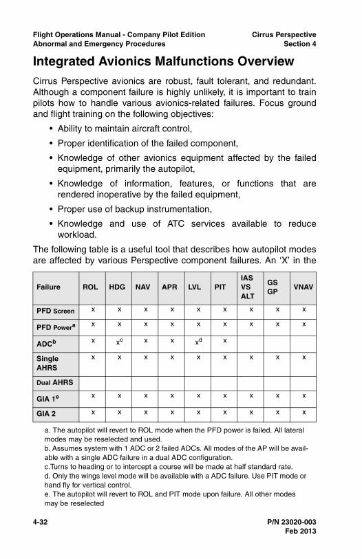
4-32 P/N 23020-003
Flight Operations Manual - Company Pilot Edition Cirrus PerspectiveAbnormal and Emergency Procedures Section 4
Integrated Avionics Malfunctions OverviewCirrus Perspective avionics are robust, fault tolerant, and redundant.Although a component failure is highly unlikely, it is important to trainpilots how to handle various avionics-related failures. Focus groundand flight training on the following objectives:
• Ability to maintain aircraft control,
• Proper identification of the failed component,
• Knowledge of other avionics equipment affected by the failedequipment, primarily the autopilot,
• Knowledge of information, features, or functions that arerendered inoperative by the failed equipment,
• Proper use of backup instrumentation,
• Knowledge and use of ATC services available to reduceworkload.
The following table is a useful tool that describes how autopilot modesare affected by various Perspective component failures. An ‘X’ in the
Failure ROL HDG NAV APR LVL PITIAS VSALT
GS GP
VNAV
PFD Screen x x x x x x x x x
PFD Powera
a. The autopilot will revert to ROL mode when the PFD power is failed. All lateral modes may be reselected and used.
x x x x x x x x x
ADCb
b. Assumes system with 1 ADC or 2 failed ADCs. All modes of the AP will be avail-able with a single ADC failure in a dual ADC configuration.
x xc
c.Turns to heading or to intercept a course will be made at half standard rate.
x x xd
d. Only the wings level mode will be available with a ADC failure. Use PIT mode or hand fly for vertical control.
x
Single AHRS
x x x x x x x x x
Dual AHRS
GIA 1e
e. The autopilot will revert to ROL and PIT mode upon failure. All other modes may be reselected
x x x x x x x x x
GIA 2 x x x x x x x x x
Feb 2013
Cirrus Perspective Flight Operations Manual - Company Pilot EditionSection 4 Abnormal and Emergency Procedures
P/N 23020-003 4-33
box means the autopilot mode will be available during the respectiveequipment failure.
Training Limitations
• Limit avionics malfunctions to VMC and when the flight cancontinue in VMC to landing,
• Note •
It is permissible to fly in IMC while in reversionary mode aslong as both the PFD and MFD screens are visible and chartsand checklists are available through other sources.
• Restore power to failed equipment before entering IMC,
• Ensure ATC communication is maintained as required duringfailures,
• Do not power down the Air Data Computer when the altitudereporting (Mode C) capability of the transponder is required byregulations or necessary for safe flight,
• Limit failures to areas of low traffic congestion and instructorworkload.
Feb 2013
4-34 P/N 23020-003
Flight Operations Manual - Company Pilot Edition Cirrus PerspectiveAbnormal and Emergency Procedures Section 4
PFD Display Failure and Reversionary ModeIt is possible to enter and exit reversionary mode in flight by pressingthe reversionary mode button.
Although all autopilot modes and all flight and navigation instrumentsare available in reversionary mode, pilots must be aware that certainMFD information, features, and functions are not available inreversionary mode.
The following information and resources will not be available while inreversionary mode:
• Approach charts,
• Checklists,
• Detailed airport and frequency information,
• Most satellite weather products
• Lean assist feature,
• TKS tank selection control,
The following information and resources will not be available with aPFD power loss:
• Baro setting unchangeable with PFD power loss; use backupaltimeter,
• Com volume and squelch adjustment,
• Loss of Com 1 and Nav 1 control; Com 1 defaults to 121.5,
• Note •
The autopilot will revert to roll mode when the PFD is powereddown. It is possible to re-engage any mode of the autopilot.
Procedure
1. Display Backup .............................................................. ACTIVATE
Press the red button between the MFD and PFD to activate thedisplay backup if the primary instruments are not displayed on theMFD. Use backup charts, checklists, and airport information asrequired.
2. Land as soon as practical.
Completion Standards
• Recognizes PFD failure and selects reversionary mode,
Feb 2013
Cirrus Perspective Flight Operations Manual - Company Pilot EditionSection 4 Abnormal and Emergency Procedures
P/N 23020-003 4-35
• Uses the correct modes of the autopilot and/or hand-flies tomaintain aircraft control within applicable private or instrumentpractical test standards,
• Determines the best course of action considering externalfactors, such as weather, ATC services available, airportservices, level of workload, and pilot proficiency,
• Utilizes backup charts and checklists,
Common Errors
• Fails to carry backup charting or checklist resources,
• Fails to recognize the autopilot change to roll mode,
• Inability to control the aircraft while scanning primaryinstruments on the MFD,
• Fails to recognize and account for the loss of Com 1.
Feb 2013

4-36 P/N 23020-003
Flight Operations Manual - Company Pilot Edition Cirrus PerspectiveAbnormal and Emergency Procedures Section 4
Air Data Computer FailureAn air data failure could be caused by faulty input information. Look forfaulty indications on the standby airspeed and altimeter to verify.Troubleshoot an ADC failure by resetting the ADC circuit breaker(s),switching to the alternate static source, and turning pitot heat on.Adjust the instrument scan to include the backup airspeed andaltimeter.
The following information will not be available during an air data failurewith a single ADC:
• PFD airspeed,
• PFD altitude,
• PFD vertical speed,
• Percent power, except SR22Ts,
• OAT,
• Wind information,
• TAS,
• Transponder Mode C (single ADC).
Pitch control is not available when the LVL autopilot mode is selected.The lateral ROL mode, or wing leveler, is available. Pilots may hand-flyor use PIT mode of the autopilot to maintain vertical control.
Procedure
1. ADC Circuit Breaker.................................................................SET
If open, reset (close) circuit breaker.
2. Revert to Standby Instruments (Altitude, Airspeed).
Verify the standby instruments are working properly bymaneuvering the aircraft slightly and looking for the expectedchange. i.e. enter a slight climb and verify that airspeed decreasesand altitude increases. Select the alternate static source and verifypitot heat is on.
3. Land as soon as practical.
Completion Standards
• Correctly identifies the ADC failure,
• Completes the Air Data Computer Failure checklist procedure,
Feb 2013
Cirrus Perspective Flight Operations Manual - Company Pilot EditionSection 4 Abnormal and Emergency Procedures
P/N 23020-003 4-37
• Checks standby airspeed and altimeter indications and selectsalternate static source and pitot heat as necessary,
• Uses the correct modes of the autopilot or hand-flies to maintainaircraft control within applicable private or instrument practicaltest standards.
Common Errors
• Fails to recognize affected modes of the autopilot,
• Fails to control the aircraft airspeed and altitude withinapplicable standards,
• Fails to notify ATC and request assistance as necessary,
• Determines the best course of action considering externalfactors such as: weather, ATC services available, airportservices, level of workload, and pilot proficiency.
Feb 2013
4-38 P/N 23020-003
Flight Operations Manual - Company Pilot Edition Cirrus PerspectiveAbnormal and Emergency Procedures Section 4
AHRS FailureIn order to lose all AHRS information, aircraft equipped with dualattitude heading and reference systems would need to have a dualAHRS failure. Dual AHRS equipped aircraft will automatically switchfrom one AHRS unit to the other if performance degradation in oneAHRS is recognized by the internal system monitoring. A dual AHRSfailure, or single AHRS failure in aircraft equipped with one AHRS, canbe recognized by the following indications:
• Loss of Synthetic Vision or horizon indications,
• Red “X” over the attitude indicator,
• “ATTITUDE FAIL” annunciator over the attitude indicator,
• Loss of heading information,
• Red “X” over the heading information,
• CDI will remain in the vertical position and provide left and rightof course deviation indications.
It is important to note that the PFD CDI needle will be oriented straightup, and still display accurate course deviations for GPS and LOCcourses. GS information will also be available while conducting ILSapproaches. TRK and DTK can be displayed on the MFD user-defineddata field for reference. Pitch and roll information is obtained throughoutside visual reference or the backup attitude indicator and headinginformation is obtained through the magnetic compass and/or groundtrack.
The GFC 700 autopilot will not be available during a dual AHRSfailure. See the Autopilot Failure Modes table for more information.
Procedure
1. Verify Avionics System has switched to functioning AHRS
If not, manually switch to functioning AHRS and attempt to bringfailed AHRS back on-line:
2. Failed AHRS Circuit Breaker....................................................SET
If open, reset (close) circuit breaker. If circuit breaker opens again,do not reset.
3. Be prepared to revert to Standby Instruments (attitude / heading).
Left and right course indications will be available on the HSI. Referto the magnetic compass for heading information.
Feb 2013
Cirrus Perspective Flight Operations Manual - Company Pilot EditionSection 4 Abnormal and Emergency Procedures
P/N 23020-003 4-39
Completion Standards
• Recognizes the failed equipment, ensures that the systemswitches the sensor information to AHRS 2 if available,
• Informs the instructor or ATC of failure, assistance needed, andremaining navigation capabilities,
• Determines the best course of action considering externalfactors such as the weather, ATC services available, airportservices, level of workload, and pilot proficiency,
• Maintains aircraft control at all times within applicable practicaltest standards for the procedure or phase of flight beingperformed.
Common Errors
• Fails to maintain aircraft control within applicable practical teststandards,
• Fails to include backup attitude indicator in instrument scan,
• Fails to include TRK and/or compass heading in scan,
• Over-controls pitch and roll,
• Neglects to inform ATC or the instructor of the failure andrequested assistance,
• Unable to adjust to a partial panel scan,
• Loses aircraft control, requiring instructor intervention, and failsto consider a CAPS deployment.
Feb 2013
4-40 P/N 23020-003
Flight Operations Manual - Company Pilot Edition Cirrus PerspectiveAbnormal and Emergency Procedures Section 4
GIA FailureThe Garmin Integrated Avionics (GIA) 1 powers COM 1, NAV 1, andGPS 1. GIA 2 powers COM 2, NAV 2, and GPS 2. In the event of afailure, the respective COM and NAV will be replaced with a red ‘x’while the COM frequency defaults to 121.5. Before simulating thisfailure by pulling the GIA 1 or 2 circuit breakers, note the frequencybeing used in the respective COM. It is very common for pilots tooverlook the loss of COM or NAV and fail to re-tune the activefrequency in COM 2. Be sure to highlight the change and reset thefrequency as necessary for uninterrupted communication with ATC orother traffic.
Procedure
1. Communication ....................................................USE COM 1 or 2
Use COM 1 if GIA 2 fails or use COM 2 if GIA 1 fails.
2. Navigation ..............................................USE VLOC 2 if applicable
3. Land as soon as practical.
Completion Standards
• Recognizes the failed equipment and resets communicationfrequencies as required,
• Re-engages the desired mode of the autopilot if necessary,
• Determines the best course of action considering externalfactors such as weather, ATC services available, airportservices, level of workload, and pilot proficiency.
Common Errors
• Fails to recognize and change COM frequencies as required,
• Fails to recognize the autopilot mode switch from NAV to ROL.
Feb 2013
Cirrus Perspective Flight Operations Manual - Company Pilot EditionSection 4 Abnormal and Emergency Procedures
P/N 23020-003 4-41
Loss of GPS IntegrityA loss of GPS integrity is an abnormal situation that requires the pilotto reference alternative forms of navigation. Pilots flying IFR shouldnotify ATC immediately of the reduced navigational capabilities. It maybe possible for ATC to provide radar vectors but expect to join victorairways to the intended destination. Also, consider the type ofapproaches available at the destination airport. A GPS approach willnot be possible with a loss of GPS integrity.
Losing GPS integrity may have more impact when flying VFR due tothe lack of ATC services available compared to when flying on an IFRflight plan. The ‘dead reckoning’ mode of the GPS will be helpful formaintaining situational awareness but use this feature with caution.VFR pilots are encouraged to switch navigation sources to VOR andnavigate on victor airways to the final destination.
Completion Standards
• Recognizes failure and selects an alternate form of navigation,
• Advises ATC and requests alternate routing if necessary,
• Determines the best course of action considering externalfactors such as weather, ATC services available, airportservices, level of workload, and pilot proficiency.
Common Errors
• Neglects to notify ATC of failure and request assistance asnecessary,
• Loses situational awareness.
Feb 2013
4-42 P/N 23020-003
Flight Operations Manual - Company Pilot Edition Cirrus PerspectiveAbnormal and Emergency Procedures Section 4
Other Emergency Procedures OverviewThe emergency and abnormal procedures discussed in this sectionare normally the result of the pilot making poor decisions, inadequateplanning, or the pilot lacking fundamental skills. These procedures arepracticed during flight training with the objective of developing decisionmaking skills to avoid these situations.
Unusual AttitudesUnusual attitudes are most likely to be encountered by pilots who lackinstrument skills, VFR pilots who inadvertently entered IMC, or pilotsexperiencing an abnormally high workload. Pilots who have enteredan unusual attitude have temporarily lost aircraft control or failed tomaintain aircraft control. At the moment of recognition, the pilot mustmake an immediate decision if the aircraft can be recovered usingtraditional recovery techniques such as: a manual recovery, engagingthe autopilot (if within limitations), or activating CAPS. Immediateaction by the pilot is required to recover the aircraft regardless of whichrecovery method is chosen.
It is important to note that pilots who have lost aircraft control may bedisoriented beyond the point where traditional, hand flown recoverytechniques are effective. CAPS activation may be the best recoveryoption available.
Preventing unusual attitudes is the best course of action. Pilots whomaintain high levels of IFR proficiency and VFR pilots who remainclear of IMC conditions are less likely to enter an unusual attitude.Frequent recurrent training is helpful, but it is also helpful to frequentlyfly in IFR in order to maintain avionics programming proficiency andfamiliarity with IFR communications and procedures.
Pilots are encourage to use the autopilot during periods of highworkload, but should not become overly-dependent on the autopilot foraircraft control.
Training Limitations
• Minimum recovery altitude is 1500 feet AGL,
• Do not exceed 60 degrees of bank or 30 degrees of pitch up ordown,
• Initiate recovery before VNE is exceeded,
• Conduct maneuver in VMC only,
Feb 2013
Cirrus Perspective Flight Operations Manual - Company Pilot EditionSection 4 Abnormal and Emergency Procedures
P/N 23020-003 4-43
Recovery (Training)
• Nose high: add power while reducing pitch to maintain airspeedand level the wings,
• Nose low: reduce power while leveling the wings and increasepitch after wings are level to stop the descent.
Completion Standards
• Promptly recognizes the unusual attitude and applies correctiveactions as described above and in the Instrument FlyingHandbook,
• Engages autopilot once the aircraft is recovered,
• Returns the aircraft to the previously assigned heading orcourse, and/or altitude,
• Regains situational awareness.
Common Errors
• Fails to scan and interpret flight attitude quickly,
• Fails to add power from a nose low unusual attitude and losessignificant airspeed and possibly aircraft control,
• Fails to return aircraft to previously assigned heading or course,and/or altitude,
Feb 2013
4-44 P/N 23020-003
Flight Operations Manual - Company Pilot Edition Cirrus PerspectiveAbnormal and Emergency Procedures Section 4
Inadvertent Flight into IMCInadvertent flight into IMC by VFR and IFR rated pilots is a majorcontributing cause of fatal accidents. Pilots that fail to brief andinterpret weather conditions or intentionally fly below low cloud basesare at the highest risk for unintentional flight into IMC.
Although prevention is the best way to avoid inadvertent flight intoIMC, pilots must be able to maintain aircraft control while safely exitingIMC. The autopilot is a great tool for assisting pilots out of IMC.However, the pilot must be capable of using the proper autopilotmodes to exit the conditions. Returning to the previous VMC is usuallythe best option. However, some situations will require alternativesolutions to exit IMC. This is particularly true while scud running closeto the ground and/or obstacles. Scud running close to the groundincreases the risk for a CFIT or loss of control accident, which aretypically fatal.
Training Limitations
• Abide by all legal altitude restrictions,
• Do not enter IMC unless on an IFR clearance,
• Flight below 500 feet AGL other than for takeoff or landing is notrecommended,
• Do not put the aircraft on a direct collision course with obstaclesor terrain other than normal descent to landing.
Completion Standards
• Maintains aircraft control within applicable practical teststandards,
• Uses autopilot correctly to assist in exiting IMC,
• Promptly and correctly changes heading and/or altitude to exitconditions,
• Seeks ATC assistance if necessary,
• Maintains situational awareness.
Common Errors
• Fails to maintain aircraft control by focusing on instrument scan,
• Fails to consider weather patterns when planning the exitstrategy,
Feb 2013
Cirrus Perspective Flight Operations Manual - Company Pilot EditionSection 4 Abnormal and Emergency Procedures
P/N 23020-003 4-45
• Does not initiate a prompt exit strategy,
• Continues to climb into IMC even at safe altitudes and expectsto escape by turning around.
Feb 2013

4-46 P/N 23020-003
Flight Operations Manual - Company Pilot Edition Cirrus PerspectiveAbnormal and Emergency Procedures Section 4
Flap MalfunctionA malfunction in the flap system typically results in the flaps failing toextend prior to approach or landing. Pilots must be aware of theadditional landing distance required due to the higher stall andapproach speeds. Pilots are encouraged to select a landing runwaythat is at least 5000 feet long for 0% flap landings. A diversion may benecessary if the runway at the intended destination is not adequate fora safe landing.
Pilots are encouraged to practice reduced flap landings during initialand recurrent training.
Training Limitations
• Reset the circuit breaker before conducting takeoff or landingpractice,
• Minimum runway length is 5000 feet for zero flap takeoff andlanding practice,
• Flaps may be failed in IMC as long as the destination ceiling andvisibility is greater than 1000 feet AGL and 3 SM.
Completion Standards
• Recognizes the failure after attempting to extend 50% flaps,
• Adjusts speed as necessary to perform a zero flap landing,
• Considers landing distance and selects an appropriate runwayfor a safe landing,
• Adheres to applicable landing completion standards.
Common Errors
• Fails to recognize the flap malfunction and continues landingunknowingly,
• Knowingly attempts a landing on a short runway with inadequatesafety margins,
• Lacks the skills to perform a zero flap landing within applicablecompletion standards.
Feb 2013
Cirrus Perspective Flight Operations Manual - Company Pilot EditionSection 4 Abnormal and Emergency Procedures
P/N 23020-003 4-47
Oxygen System MalfunctionAll pilots flying an oxygen and/or turbo equipped Cirrus aircraft areencouraged to attend hypoxia training every 5 years. Information aboutfacilities that offer this training can be found on the Cirrus TrainingPortal. Be cognizant of hypoxia signs and symptoms and continuouslymonitor oxygen saturation levels with a pulse oximeter when operatingat altitudes that require the use of supplemental oxygen.
It is critical to ensure adequate oxygen is available for the intendedflight considering altitude and passengers. Careful preflight of allregulators, masks, cannulas, oxygen flow, hoses, and connections isrequired.
An O2 malfunction at high altitude is an emergency situation requiringimmediate and decisive action by the pilot. If supplemental oxygen isnot available at high altitude, an emergency descent must be initiated.Consider using the autopilot in IAS mode set to VNO with the altitudebug set to 10,000 feet MSL, or higher if terrain dictates.
• WARNING •
Intentionally removing supplemental oxygen at or abovealtitudes where supplemental oxygen is required by regulationis reckless and unsafe. The supplemental oxygen system willremain on during all O2 malfunction scenarios. Thesescenarios are intended to teach pilots how to respond tovarious oxygen failures, not to demonstrate hypoxia signs,symptoms, and recovery.
Training Limitations
• Malfunction limited to VFR in airspace and terrain that allows anemergency descent to a minimum of 12,500 feet MSL,
• Oxygen system and masks or cannulas will remain on at allaltitudes that require supplemental oxygen.
Completion Standards
• Promptly responds to the malfunction and initiates anemergency descent to a safe altitude,
• Declares an emergency when workload permits andcoordinates with ATC as required,
Feb 2013
4-48 P/N 23020-003
Flight Operations Manual - Company Pilot Edition Cirrus PerspectiveAbnormal and Emergency Procedures Section 4
• Recognizes signs and symptoms of hypoxia in passengers andresponds accordingly.
Common Errors
• Does not understand the severity of an oxygen systemmalfunction at high altitude,
• Fails to perform an emergency descent as described in theemergency descent completion standards.
Feb 2013
Cirrus Perspective Flight Operations Manual - Company Pilot EditionSection 4 Abnormal and Emergency Procedures
P/N 23020-003 4-49
Power Lever Linkage FailureA stuck throttle results from a linkage failure between the power leverand the throttle plate. The power may be at a high or low powersetting. Individual circumstances dictate the proper reaction by thepilot.
When the power is stuck low and the aircraft is unable to sustain levelflight, the pilot should establish the aircraft at best glide speed andprepare for an emergency landing. CAPS should be considered andactivated above 2,000 feet AGL when the successful outcome of aforced landing is in doubt.
A stuck throttle with a high power setting will require the pilot toperform a power-off landing. The pilot should position the aircraftwithin safe gliding distance from the airport, a runway greater then5,000 feet is recommended, and then shut the engine off with themixture control and establish best glide. The pilot may enrichen themixture to restart the engine if it appears the aircraft will come up shortto the runway.
Pilots who are not confident in their ability to perform this procedureshould consider CAPS as an alternative to the power-off landing.
Procedure
1. Power Lever Movement...................................................... VERIFY
Sweep the power lever slowly to determine if any control remains.
2. Power .............................................................................SET if able
3. Flaps ........................................................................ SET if needed
With a high power setting, consider decreasing airspeed byincreasing the aircraft’s pitch to flap speeds. Set flaps as desiredand continue descent.
4. Mixture ..................................... AS REQUIRED (full rich to cut-off)
To perform a landing with a stuck throttle, the engine will need tobe shut off via the mixture control. It is best to position the aircraftwithin safe gliding distance before turning the engine off.
5. Land as soon as possible.
A stuck throttle should be treated as an emergency situation.Inform ATC of situation and request assistance and priorityhandling as necessary. Be prepared for a power-off landing.
Feb 2013
4-50 P/N 23020-003
Flight Operations Manual - Company Pilot Edition Cirrus PerspectiveAbnormal and Emergency Procedures Section 4
Completion Standards
• For takeoff scenario, promptly reduces throttle to idle andapplies brakes as required to stop the aircraft on the runway,
• For landing scenario, simulates notifying ATC of emergency andrequests assistance as necessary,
• For landing scenario, reduces risk by selecting a larger runway,
• For landing scenario, puts the aircraft into a position where astabilized approach to a power-off landing can be accomplished,
• For landing scenario, considers methods of extending glidedistance or performing a go-around if necessary.
Common Errors
• Does not consider engine shutdown and power-off approach forresolving scenario,
• Fails to abort takeoff promptly,
• Fails to execute a power-off approach within applicablecompletion standards.
Feb 2013

Cirrus Perspective Flight Operations Manual - Company Pilot EditionSection 4 Abnormal and Emergency Procedures
P/N 23020-003 4-51
Loss of Brake PressurePilots are encouraged to check brakes before taxi and during thedescent checklist during each flight operation as detailed in the normalprocedures checklist. In the event of a loss of brake pressure duringtaxi, the engine should be shutdown before the aircraft comes intocollision hazard with objects on the ground. The aircraft should betowed and repaired prior to flight or self-propelled movement on theground.
If brake pressure is lost during flight, select a wide runway that is atleast 5,000 feet in length. Notify ATC of the failure to ensure landingseparation is accounted for. Touchdown close to the approach end ofthe runway with minimum speed. For a single brake failure, land on theside of runway corresponding to the failed brake. Use rudder to steerand counteract the forces of the remaining brake. Discontinue brakingwhen rudder authority no longer over controls the single remainingbrake.
Training Limitations
• Discontinue scenario and apply brake pressure as necessary toavoid collision or runway overrun,
• Practice no-brake landings at a runway that is at least 5,000feet,
• Limit failure to VMC.
Completion Standards
• For taxi scenario, adheres to the Brake Failure During Taxichecklist procedures as necessary,
• For taxi scenario, shuts the engine down and stop the aircraftforward movement when necessary,
• For landing scenario, selects an appropriate runway forperforming a no-brake landing,
• For landing scenario, references the Landing with Failed Brakeschecklist procedure,
• For landing scenario, simulates informing ATC of malfunctionand requests assistance as necessary,
• Lands on correct side of the runway for a single brake failureand maintains directional control.
Feb 2013
4-52 P/N 23020-003
Flight Operations Manual - Company Pilot Edition Cirrus PerspectiveAbnormal and Emergency Procedures Section 4
Common Errors
• For taxi scenario, fails to shut engine down and collides withground structures,
• For landing scenario, fails to pump the brakes to restorepressure,
• For landing scenarios, fails to select an adequate runway,
• Fails to land on correct side of the runway for a single brakefailure.
Feb 2013
Cirrus Perspective Flight Operations Manual - Company Pilot EditionSection 4 Abnormal and Emergency Procedures
P/N 23020-003 4-53
Open DoorDoors that close hard or open in flight require service. When properlyadjusted, Cirrus doors will remain closed and are easy to operate. It isrecommended to close the passenger door from outside the aircraftwhen flying with infrequent flyers. Always check the upper and lowerlatches of each door before departure and listen for increased cabinnoise during the engine run-up to identify an improperly shut door.
Although an open door is undesirable due to the increase in cabinnoise, possible decrease in temperature, and possible precipitation inthe cabin, the aircraft handling characteristics are unchanged. It is notpossible to close the door in flight due to the aerodynamic forces. It isrecommended to land and stop the aircraft to close the door if the dooropens in flight or was left open during departure. This is not anemergency landing. Pilots should use normal power settings, speeds,and aircraft configuration for landing. Do not become overly distractedby the open door and focus on maintaining aircraft control.
Completion Standards
• Maintains aircraft control,
• Communicates intentions to ATC and returns for a landing,
• Listens for signs of an open door during run-up and early in thetakeoff roll,
• Aborts takeoff only when sufficient runway remains for stoppingwithout excessive brake pressure.
Common Errors
• Becomes preoccupied with open door and loses focus onprimary pilot responsibilities,
• Attempts to slow and close door in flight.
•
Feb 2013

4-54 P/N 23020-003
Flight Operations Manual - Company Pilot Edition Cirrus PerspectiveAbnormal and Emergency Procedures Section 4
Feb 2013
Intentionally Left Blank

Cirrus Perspective Flight Operations Manual - Company Pilot EditionSection 5 Maneuvers
P/N 23020-003 5-1
Section 5Maneuvers
GeneralFollow these guidelines for set up and execution of the followingmaneuvers. During these maneuvers, pilots should be alert toavailable forced landing areas. The area chosen should be clear of anyobstacles or terrain and away from communities, livestock, or groupsof people to prevent possible annoyance or hazards to others.
Reference the Airplane Flying Handbook FAA-H-8083-3a for moreinformation.
Minimum Recovery Altitude
• Performance maneuvers, slow flight, and stalls should beperformed with a minimum recovery altitude of 1,500 feet AGL,
• Ground reference maneuvers should be performed at 1,000feet AGL or applicable traffic pattern altitude.
Mixture Control
For all maneuvering flight, the mixture should be set to allow maximumpower if needed.
• SR20 - Set mixture full rich
• SR22 - Set mixture per the Max Power Fuel Flow placard or thetop of the green arc on the fuel flow gauge
• SR22TN - Set mixture full rich
• SR22T - Set mixture full rich
Feb 2013
5-2 P/N 23020-003
Flight Operations Manual - Company Pilot Edition Cirrus PerspectiveManeuvers Section 5
Steep Turns (Private and Commercial)Enter this maneuver at 120 KIAS by smoothly banking the aircraft to45 degrees (Private) or 50 degrees (Commercial) and simultaneouslyadding back pressure to maintain altitude. Maintain coordination withrudder. Additional power may be necessary to maintain airspeed.Continue the turn for 360 degrees. Start the roll out approximately 10degrees before completing the full turn and simultaneously releaseback pressure. Reduce any power that was added during themaneuver.
Limitations
• Minimum recovery altitude: 1,500 feet AGL,
• VMC only.
Execution
• Execute clearing turns,
• Airspeed 120 KIAS,
• SR20 - 60% Power / 21" MP (approximately),
• SR22 - 30% Power / 18" MP (approximately),
• SR22TN - 55% Power / 20" MP (approximately),
• SR22T - 50% Power / 18” MP (approximately).
• Bank Angle 45º (Private) or 50º (Commercial).
Recovery
• Smoothly roll out on desired heading while relaxing elevatorback pressure to maintain altitude,
• Reduce power to maintain airspeed,
• Continue flight as desired.
Completion Standards
• Exhibits knowledge of the elements related to this maneuverand complies with limitations, execution, and recoveryprocedures described in this manual,
• Maintains altitude +/-100 feet, airspeed +/-10 KIAS, bank angle+/- 5 degrees, and rolls out on entry heading +/-10 degrees,
• Maintains 45 degree (private), or 50 degrees (commercial),
Feb 2013
Cirrus Perspective Flight Operations Manual - Company Pilot EditionSection 5 Maneuvers
P/N 23020-003 5-3
• Divides attention between outside visual reference andinstrument scan (VMC),
• Maintains aircraft coordination during maneuver,
• Smoothly rolls into opposite direction turn as requested byinstructor.
Common Errors
• Adds excessive elevator back pressure while rolling into bankcausing the aircraft to climb and lose airspeed,
• Over-banks or excessively changes angle of bank, causingaltitude and airspeed fluctuations,
• Fails to reduce back pressure and/or reduce power-onmaneuver rollout causing the aircraft to climb and/or accelerate,
• Uses abrupt and excessive control inputs.
Feb 2013
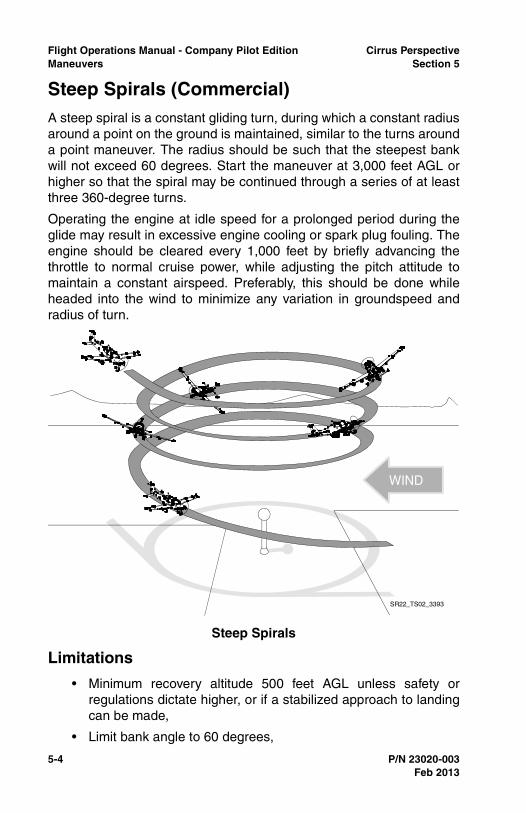
5-4 P/N 23020-003
Flight Operations Manual - Company Pilot Edition Cirrus PerspectiveManeuvers Section 5
Steep Spirals (Commercial)A steep spiral is a constant gliding turn, during which a constant radiusaround a point on the ground is maintained, similar to the turns arounda point maneuver. The radius should be such that the steepest bankwill not exceed 60 degrees. Start the maneuver at 3,000 feet AGL orhigher so that the spiral may be continued through a series of at leastthree 360-degree turns.
Operating the engine at idle speed for a prolonged period during theglide may result in excessive engine cooling or spark plug fouling. Theengine should be cleared every 1,000 feet by briefly advancing thethrottle to normal cruise power, while adjusting the pitch attitude tomaintain a constant airspeed. Preferably, this should be done whileheaded into the wind to minimize any variation in groundspeed andradius of turn.
Limitations
• Minimum recovery altitude 500 feet AGL unless safety orregulations dictate higher, or if a stabilized approach to landingcan be made,
• Limit bank angle to 60 degrees,
Steep Spirals
WIND
SR22_TS02_3393
Feb 2013
Cirrus Perspective Flight Operations Manual - Company Pilot EditionSection 5 Maneuvers
P/N 23020-003 5-5
• Limited to VMC.
Execution
• Reduce throttle to idle,
• Adjust aircraft pitch to maintain altitude until VG is reached,
• Lower nose to maintain VG over the selected reference point,
• Adjust bank angle as necessary to fly a constant radius overselected reference point.
• Clear engine every 1,000 feet,
• Complete a minimum of at least three, 360-degree turns.
Recovery
• Add power as necessary and climb to desired altitude, or
• Continue landing if a stabilized approach to landing can bemaintained.
Completion Standards
• Selects an altitude sufficient to continue through a series of atleast three 360-degree turns,
• Selects a suitable ground reference point,
• Applies wind-drift correction to track a constant radius circlearound the selected reference point with bank not to exceed 60degrees,
• Divides attention between airplane control and ground track,while maintaining coordinated flight,
• Maintains VG +/-10 KIAS, rolls out toward object or specifiedheading +/- 10 degrees,
• Positions aircraft for a stabilized approach to landing andcompletes a power-off landing within applicable completionstandards.
Common Errors
• Fails to maintain constant airspeed resulting in ground speedchanges and difficulty maintaining a constant radius,
• Fails to decrease bank angle sufficiently on the upwind side toprevent getting blown over the reference point,
Feb 2013
5-6 P/N 23020-003
Flight Operations Manual - Company Pilot Edition Cirrus PerspectiveManeuvers Section 5
• Fails to account for wind changes throughout the descent,
• Mis-judges descent rate and fails to position the aircraft for astabilized approach to landing if a landing was attempted.
Feb 2013
Cirrus Perspective Flight Operations Manual - Company Pilot EditionSection 5 Maneuvers
P/N 23020-003 5-7
Chandelle (Commercial)A chandelle is a maximum performance climbing turn beginning fromapproximately straight-and-level flight, and ending at the completion ofa precise 180 degree turn in a wings-level, nose-high attitude at theminimum controllable airspeed. The maneuver demands that themaximum flight performance of the airplane be obtained; the airplaneshould gain the most altitude possible for a given degree of bank andpower setting without stalling.
Since numerous atmospheric variables beyond control of the pilot willaffect the specific amount of altitude gained, the quality of theperformance of the maneuver is not judged solely on the altitude gain,but by the pilot’s overall proficiency as it pertains to climb performancefor the power and bank combination used, and to the elements ofpiloting skill demonstrated.
Prior to starting a chandelle, the flaps should be in the UP position,power set for 120 KIAS, and the airspace behind and above clear ofother air traffic. The maneuver should be entered from straight-and-level flight at 120 KIAS. After the appropriate airspeed and powersetting have been established, the chandelle is started by smoothlyentering a coordinated turn with an angle of bank appropriate for theairplane being flown. Increase to full power as the climb is initiated.
Normally, this angle of bank should not exceed approximately 30degrees. After the appropriate bank is established, a climbing turnshould be started by smoothly applying back-elevator pressure toincrease the pitch attitude at a constant rate and to attain the highestpitch attitude as 90 degrees of the turn is completed. Apply rudderinputs to maintain coordinated flight throughout the maneuver.
Feb 2013
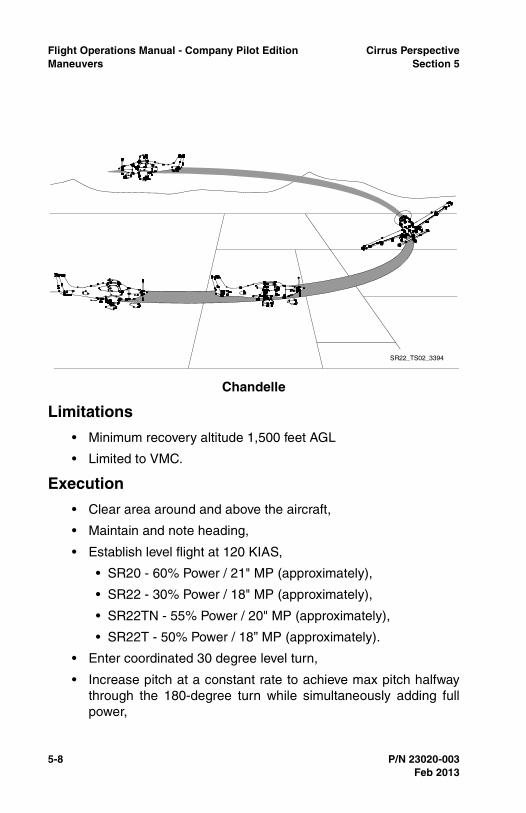
5-8 P/N 23020-003
Flight Operations Manual - Company Pilot Edition Cirrus PerspectiveManeuvers Section 5
Limitations
• Minimum recovery altitude 1,500 feet AGL
• Limited to VMC.
Execution
• Clear area around and above the aircraft,
• Maintain and note heading,
• Establish level flight at 120 KIAS,
• SR20 - 60% Power / 21" MP (approximately),
• SR22 - 30% Power / 18" MP (approximately),
• SR22TN - 55% Power / 20" MP (approximately),
• SR22T - 50% Power / 18” MP (approximately).
• Enter coordinated 30 degree level turn,
• Increase pitch at a constant rate to achieve max pitch halfwaythrough the 180-degree turn while simultaneously adding fullpower,
Chandelle
SR22_TS02_3394
Feb 2013
Cirrus Perspective Flight Operations Manual - Company Pilot EditionSection 5 Maneuvers
P/N 23020-003 5-9
• At the 90-degree point in the turn, maintain maximum pitchattitude while decreasing angle of bank at a constant rate to rollout wings level 180-degrees from starting heading,
• Hold the maximum pitch attitude momentarily at the 180-degree point, then reduce pitch to maintain level flight.
Recovery
• Reduce power to normal cruise power setting once aircraft hasaccelerated as desired.
Completion Standards
• Starts and completes maneuver higher than 1,500 feet AGL,
• Enters the maneuver at 120 KIAS with flaps UP,
• Establishes a 30-degree left or right turn,
• Simultaneously applies power and pitch to maintain a smooth,coordinated climbing turn to the 90-degree point, with aconstant bank angle,
• Begins a coordinated constant rate rollout from the 90-degreepoint to the 180-degree point maintaining full power and aconstant pitch attitude,
• Completes rollout at the 180-degree point +/-10 degrees, justabove a stall airspeed, and maintaining that airspeedmomentarily while avoiding a stall,
• Resumes straight-and-level flight with a minimum loss ofaltitude.
Common Errors
• Establishes a maximum pitch that is too great, resulting in astall condition,
• Fails to maintain coordination throughout maneuver,
• Fails to maintain a constant rate of pitch or bank changesduring the appropriate phases of the maneuver,
• Fails to divide attention and look outside at visual referencepoints.
Feb 2013
5-10 P/N 23020-003
Flight Operations Manual - Company Pilot Edition Cirrus PerspectiveManeuvers Section 5
Lazy Eights (Commercial)The lazy eight is a maneuver designed to develop perfect coordinationof controls through a wide range of airspeeds and altitudes so thatcertain accuracy points are reached with planned attitude andairspeed. In its execution, the dive, climb, and turn are all combined,and the combinations are varied and applied throughout theperformance range of the airplane. It is the only standard flight trainingmaneuver during which at no time do the forces on the controls remainconstant.
The lazy eight as a training maneuver has great value since constantlyvarying forces and attitudes are required. These forces must beconstantly coordinated, due not only to the changing combinations ofbanks, dives, and climbs, but also to the constantly varying airspeed.The maneuver helps develop subconscious feel, planning, orientation,coordination, and speed sense. It is not possible to do a lazy eightmechanically, because the control pressures required for perfectcoordination are never exactly the same.
A lazy eight consists of two 180-degree turns, in opposite directions,while making a climb and a descent in a symmetrical pattern duringeach of the turns. At no time throughout the lazy eight is the airplaneflown straight and level; instead, it is rolled directly from one bank tothe other with the wings level only at the moment the turn is reversedat the completion of each 180-degree change in heading. As an aid tomaking symmetrical loops of the “eight” during each turn, prominentreference points should be selected on the horizon. The referencepoints selected should be 45-degrees, 90-degrees, and 135-degreesfrom the direction in which the maneuver is begun.
Prior to performing a lazy eight, the airspace behind and above shouldbe clear of other air traffic. The maneuver should be entered fromstraight-and-level flight at 120 KIAS. Power remains constantthroughout the maneuver.
Feb 2013

Cirrus Perspective Flight Operations Manual - Company Pilot EditionSection 5 Maneuvers
P/N 23020-003 5-11
Limitations
• Minimum recovery altitude 1,500 feet AGL,
• Limited to VMC.
Execution
• Clear area around aircraft,
• Flaps UP,
• Establish level flight at 120 KIAS,
Lazy Eights
SR22_TS02_3392
ENTRY:1. LEVEL FLIGHT2. MANEUVERING OR CRUISE SPEED WHICHEVER IS LESS OR MANUFACTURER"S RECOMMENDED SPEED
180° POINT:1. LEVEL FLIGHT2. ENTRY AIRSPEED3. ALTITUDE SAME AS ENTRY ALTITUDE
90° POINT:1. BANK APPROX 30°2. MINIMUM SPEED3. MAXIMUM ALTITUDE4. LEVEL PITCH ATTITUDE
45° POINT:1. MAX. PITCH-UP ALTITUDE2. BANK 15° (APPROX.)
135° POINT:1. MAX. PITCH-DOWN2. BANK 15° (APPROX.)
Feb 2013
5-12 P/N 23020-003
Flight Operations Manual - Company Pilot Edition Cirrus PerspectiveManeuvers Section 5
• SR20 - 60% Power / 21" MP (approximately),
• SR22 - 30% Power / 18" MP (approximately),
• SR22TN - 55% Power / 20" MP (approximately),
• SR22T - 50% Power / 18” MP (approximately).
• Control the aircraft to achieve the following throughout themaneuver,
• At the 45-degree reference, maximum pitch up attitude withapproximately 15 degrees of bank,
• At the 90-degree reference, maximum bank of 30 degreeswith level pitch,
• At the 135-degree reference, maximum pitch down attitudewith approximately 15 degrees of bank,
• At the 180-degree point, momentary level pitch and bank asthe turn direction is changed,
• Proper coordination,
• Constantly changing pitch and roll rates.
Recovery
• Apply power as necessary to resume normal flight.
Completion Standards
• Establishes the recommended entry configuration, power, andairspeed,
• Maintains altitude tolerance at 180-degree points, +/-100 feetfrom entry altitude,
• Maintains airspeed tolerance at the 180-degree point, +/-10KIAS from entry airspeed,
• Maintains heading tolerance at the 180-degree point, +/- 10degrees,
• Continues the maneuver through the number of symmetricalloops specified and resumes straight and level flight.
Common Errors
• Rushes through maneuver and requires non-constant rates ofpitch or roll change to match desired reference points,
• Fails to monitor area for other traffic during maneuver,
Feb 2013
Cirrus Perspective Flight Operations Manual - Company Pilot EditionSection 5 Maneuvers
P/N 23020-003 5-13
• Uses erratic or rough control inputs, usually caused by attemptsto counteract poor planning.
Feb 2013
5-14 P/N 23020-003
Flight Operations Manual - Company Pilot Edition Cirrus PerspectiveManeuvers Section 5
Maneuvering during Slow FlightPractice this maneuver with a variety of flap configurations whileclimbing, descending, and turning. Enter the maneuver in level flightand smoothly reduce power. Maintain altitude while the aircraft slowsto the desired airspeed and trim the aircraft. Add flaps as desired atVFE. Add power as necessary to maintain the desired altitude.Maintain coordination throughout the maneuver with rudder control.Recover from this maneuver if a stall is encountered.
Limitations
• Minimum recovery altitude: 1,500 feet AGL,
• Limited to VMC.
Execution
• Execute clearing turns,
• Reduce power,
• SR20 - 20% Power / 15" MP (approximately),
• SR22 - 15% Power / 12" MP (approximately),
• SR22TN - 25% Power / 12” MP (approximately),
• SR22T - 30% Power / 12.5” MP (approximately).
• Flaps as desired (0% - 100%),
• Bank angle as desired (20º maximum),
• Airspeed - an airspeed at which any further increase in angle ofattack, increase in load factor, or reduction in power wouldresult in an immediate stall (current PTS standards),
• Power as required for level flight or desired climb or descentrate.
Recovery
• Reduce angle of attack and level wings,
• Apply full power,
• Flaps 50%,
• Accelerate to VY,
• Flaps 0%,
• SR20 - 85 KIAS,
Feb 2013
Cirrus Perspective Flight Operations Manual - Company Pilot EditionSection 5 Maneuvers
P/N 23020-003 5-15
• SR22 - 80 KIAS.
• Clear of terrain and obstacles,
• Positive rate of climb.
Completion Standards
• Exhibits knowledge of the elements related to this maneuverand complies with limitations, execution, and recoveryprocedures described in this manual,
• (Private) Maintains altitude +/-100 feet, airspeed +10/-0 KIAS,bank angle +/- 10 degrees, desired heading +/-10 degrees,
• (Commercial) Maintains altitude +/-50 feet, airspeed +5/-0KIAS, bank angle +/-5 degrees, desired heading +/-10 degrees,
• Accomplishes coordinated straight-and-level flight, turns,climbs, and descents with flap configurations specified by theinstructor,
• Divides attention between visual references and instrumentscan.
Common Errors
• Fails to maintain coordination during maneuver,
• Fails to recognize the signs of an impending stall,
• Fails to understand and apply proper power and pitch controlinputs when changing or correcting airspeed and/or altitudedeviations.
Feb 2013
5-16 P/N 23020-003
Flight Operations Manual - Company Pilot Edition Cirrus PerspectiveManeuvers Section 5
Power-Off StallsPractice this maneuver with varying flap configurations. Enter thismaneuver from a level attitude by reducing the power and adding flapsas desired at VFE. At 80 KIAS establish a descent of approximately500 FPM, straight or turning. Once a stabilized descent is established,reduce power to idle and gradually increase pitch to a normaltouchdown attitude (7.5 degrees approximately). Adjust pitch toreduce airspeed approximately 1 KIAS / second. Recovery can beinitiated at the incipient phase or full stall.
Limitations
• Minimum recovery altitude: 1,500 feet AGL,
• Limited to VMC.
Execution
• Execute clearing turns,
• Flaps as desired (0% - 100%),
• Establish glide or gliding turn slowing to 80 KIAS,
• SR20 - 20% Power / 15" MP (approximately),
• SR22 - 15% Power / 12" MP (approximately),
• SR22TN - 25% Power / 12" MP (approximately),
• SR22T - 30% Power / 12.5” MP (approximately).
• Descent rate 500 fpm (approximately),
• 20º max bank angle,
• Reduce throttle to idle and increase pitch to a normal landingattitude (5º to 7.5º) and induce a stall.
Recovery
• Reduce angle of attack and level wings,
• Apply full power,
• Flaps 50%,
• Accelerate to VY,
• Flaps 0%,
• Airspeed 80 KIAS (SR22) 85 KIAS (SR20),
• Clear of terrain and obstacles,
Feb 2013

Cirrus Perspective Flight Operations Manual - Company Pilot EditionSection 5 Maneuvers
P/N 23020-003 5-17
• Positive rate of climb.
Completion Standards
• Exhibits knowledge of the elements related to this maneuverand complies with limitations, execution, and recoveryprocedures described in this manual,
• Describes factors that affect stall speed and situations whereunintentional stalls are likely to occur,
• Transitions smoothly from the approach or landing attitude to apitch attitude that will induce a stall,
• (Private) Maintains a specified heading +/-10 degrees instraight flight, maintains a specified angle of bank not to exceed20 degrees, angle of bank +/-10 degrees in turning flight whileinducing stall,
• (Commercial) Maintains a specified heading +/-10 degrees instraight flight, maintains a specified angle of bank not to exceed20 degrees, angle of bank +/-5 degrees in turning flight whileinducing stall,
• Recognizes and recovers promptly after the stall occurs bysimultaneously reducing the angle of attack, increasing powerto maximum allowable, and leveling the wings to return to astraight-and-level flight attitude with a minimum loss of altitude,
• Retracts flaps from 100% to 50% once the descent has beenstopped and then retracts flaps from 50% to 0% once a positiverate of climb is established with airspeed at or above thatrecommended,
• Returns to the previous altitude, heading, and airspeedspecified by the instructor.
Common Errors
• Fails to add sufficient rudder input during stall recovery,
• Retracts flaps prematurely during recovery, resulting inexcessive loss of altitude,
• Fails to promptly apply full power resulting in an excessive lossof altitude and/or delayed recovery,
• Increases pitch excessively, resulting in a secondary orunintentional stall.
Feb 2013
5-18 P/N 23020-003
Flight Operations Manual - Company Pilot Edition Cirrus PerspectiveManeuvers Section 5
Power-On StallsPractice this maneuver with 0% and/or 50% flaps, straight and turning.Enter the maneuver from level flight by reducing power and addingflaps as desired at VFE. Slow the aircraft to VR while maintainingaltitude. At VR smoothly apply a minimum of 65% power and pitch theaircraft at an angle to induce a stall. Apply rudder to maintaincoordination. Recover from this maneuver at the incipient phase or fullstall.
Limitations
• Minimum recovery altitude: 1,500 feet AGL,
• Limited to VMC,
• Limit nose high attitude to 30 degrees as per Private andCommercial Practical Test Standards,
• Minimum percent power is 65%
Execution
• Execute clearing turns,
• Flaps 0% or 50% as desired,
• Airspeed- slow to VR,
• SR20 - 20% Power / 15" MP (approximately),
• SR22 - 15% Power / 12" MP (approximately),
• SR22TN - 25% Power / 12" MP (approximately),
• SR22T - 30% Power / 12.5” MP (approximately).
• Bank angle as desired (20 degrees maximum),
• Apply a minimum of 65% power,
• Increase pitch angle to induce stall (maximum 30-degrees pitchattitude).
Recovery
• Reduce angle of attack and level wings,
• Verify full power,
• Accelerate to VY,
• Flaps 0%,
Feb 2013
Cirrus Perspective Flight Operations Manual - Company Pilot EditionSection 5 Maneuvers
P/N 23020-003 5-19
• Airspeed 80 KIAS (SR22) 85 KIAS (SR20),
• Clear of terrain and obstacles,
• Positive rate of climb.
Completion Standards
• Exhibits knowledge of the elements related to this maneuverand complies with limitations, execution and recoveryprocedures described in this manual,
• (Private) Maintains a specified heading within +/-10 degrees instraight flight, and a specified angle of bank (less than 20degrees) within +/-10 degrees,
• (Commercial) Maintains a specified heading within +/-5degrees in straight flight, and a specified angle of bank (lessthan 20 degrees) within +/-10 degrees,
• Recognizes and recovers promptly after the stall occurs bysimultaneously reducing the angle of attack, increasing poweras appropriate, and leveling the wings to return to a straight-and-level flight attitude with a minimum loss of altitude,
• Retracts flaps from 50% to 0% when the aircraft has resumed aclimb at or above the recommended flap retraction airspeed.
Common Errors
• Fails to apply proper rudder inputs to maintain coordinationduring maneuver,
• Reduces pitch attitude too much during recovery, causing anexcessive loss of altitude,
• Fails to maintain heading within standards through properrudder and aileron inputs during maneuver, setup, andrecovery.
• Exhibits a lack of knowledge of elements related to spinsprevention and spin recovery.
Feb 2013
5-20 P/N 23020-003
Flight Operations Manual - Company Pilot Edition Cirrus PerspectiveManeuvers Section 5
Autopilot Stall RecognitionThe purpose of this maneuver is to identify the conditions when a stallwith the autopilot engaged may occur, to recognize the effects of animpending autopilot stall, and to learn the recovery procedure. Do notexceed any autopilot limitations during this maneuver. The maneuveris started by programming the autopilot for conditions it is not capableof maintaining (excessive climb rate, insufficient power, etc). Autopilotswith Perspective software load 764.09 or later have low-speedprotection and respond differently then previous software loads. Whilesoftware loads 764.08 and prior disconnect the autopilot below 80KIAS, later loads will remain engaged and will switch mode priorities tomaintain a flying airspeed above the stall speed.
Regardless of the software load, the highest priority is to regainaircraft control by decreasing the angle of attack and increasingairspeed. Reference the correct section below for maneuver setup andexecution depending on the Perspective software load.
Limitations
• Minimum recovery altitude: 1,500 feet AGL,
• Limited to VMC,
• All autopilot limitations in the AFM apply.
Execution
• Execute clearing turns,
• Flaps as desired,
• Autopilot lateral and pitch modes as desired,
• Throttle insufficient for sustained flight.
Recovery for Software Load 764.09 or later
• Smoothly apply full throttle, and
• Verify and maintain aircraft coordination,
• Reduce throttle as necessary once normal flight is resumed.
Recovery for Software Load 764.08 or prior
• Disconnect autopilot and simultaneously:
• Reduce angle of attack,
• Increase throttle as required,
Feb 2013
Cirrus Perspective Flight Operations Manual - Company Pilot EditionSection 5 Maneuvers
P/N 23020-003 5-21
• Level wings,
• After initial recovery, return aircraft to previously assignedheading, altitude, or desired flight condition.
Completion Standards
• Describes situations likely to lead to an autopilot stall or under-speed condition,
• Exhibits knowledge of the elements related to autopilot stallsand complies with limitations, execution and recoveryprocedures described in this manual,
• Recognizes and promptly corrects from an impending autopilotstall or slow flight condition,
• Minimizes loss of altitude by applying proper power inputs andcontrols aircraft pitch as necessary,
• Returns to previously assigned or desired flight parameters andadvises ATC of any inability to maintain an ATC clearance.
Common Errors
• Lacks knowledge of autopilot limitations,
• Becomes complacent and neglects to actively scan andmonitor flight status during autopilot operations,
• Fails to verify active and armed autopilot modes,
• Fails to manage power required to maintain the desiredairspeed and/or altitude.
Feb 2013
5-22 P/N 23020-003
Flight Operations Manual - Company Pilot Edition Cirrus PerspectiveManeuvers Section 5
Ground Reference ManeuversGround reference maneuvers described in this section are required byPrivate Pilot and Commercial Practical Test Standards. Practicingthese maneuvers helps pilots develop fundamental skills of aircraftcontrol, division of attention, and correction for wind drift. The skillsdeveloped while performing these maneuvers have real-lifeapplicability and are the basis for many flight operations performedduring normal day-to-day flight operations. Rated pilots shouldpractice these maneuvers to hone skills during recurrent trainingevents and flight reviews.
Complete ground reference maneuvers in an area with an availableemergency landing spot. Do not practice ground reference maneuversin a noise sensitive area. Be sure to avoid areas with towers orcongested traffic.
The decision to deploy CAPS must be made immediately below 2,000feet AGL. Pre-brief if CAPS will be a viable option to increase survivalpotential if a catastrophic engine failure is experienced during groundreference maneuvers.
It may be beneficial to inhibit TAWS during ground referencemaneuvers to reduce cockpit distractions. Ensure the area is free ofobstacle or terrain hazards before inhibiting TAWS. Remember to un-inhibit TAWS at the maneuver completion.
Limitations
• Limited to VMC,
• Minimum altitude 600 feet AGL,
• Within all other regulatory altitude restrictions,
• Within a position to make an emergency landing.
Feb 2013

Cirrus Perspective Flight Operations Manual - Company Pilot EditionSection 5 Maneuvers
P/N 23020-003 5-23
Rectangular Course (Private)Select a rectangular area approximately one mile in length by aminimum of 1/2 mile wide. Enter the maneuver 45 degrees to thedownwind at 1,000 feet AGL. Fly a ground track which is equidistantfrom all sides of the rectangular area while accounting for wind driftand maintaining constant airspeed and altitude.
Practice this maneuver using an actual runway traffic pattern at anuncontrolled airport with no traffic conflicts when developing basictraffic pattern skills and wind drift correction skills.
Execution
• Execute clearing turns,
• Airspeed 100 KIAS,
• SR20 - 50% Power / 20" MP (approximately),
• SR22 - 30% Power / 15" MP (approximately),
Rectangular Course
Feb 2013
5-24 P/N 23020-003
Flight Operations Manual - Company Pilot Edition Cirrus PerspectiveManeuvers Section 5
• SR22TN - 50% Power / 15" MP (approximately),
• SR22T - 40% Power / 15” MP (approximately).
• Enter on the downwind leg at a 45-degree angle,
• Maintain approximately 1/2 mile from the reference line.
Recovery
• Add power as necessary and climb to a desired altitude.
Completion Standards
• Selects a suitable area to perform the maneuver consideringemergency landing availability, noise abatement, and obstacleand terrain clearance,
• Applies adequate wind-drift correction during straight-and-turning flight to maintain a constant ground track around therectangular reference area,
• Divides attention between aircraft control and ground trackwhile maintaining coordinated flight,
• Maintains altitude, +/-100 feet, airspeed +/-10 KIAS.
Common Errors
• Fails to apply proper rudder inputs to maintain coordinatedflight during the maneuver,
• Fails to clear the area for traffic, terrain, or obstacle hazards,
• Over controls pitch and roll excessively and exceedsperformance standards,
• Fails to plan and anticipate wind correction for future segments,
• Displays an inability to quickly scan airspeed and altitudeinstrumentation.
Feb 2013
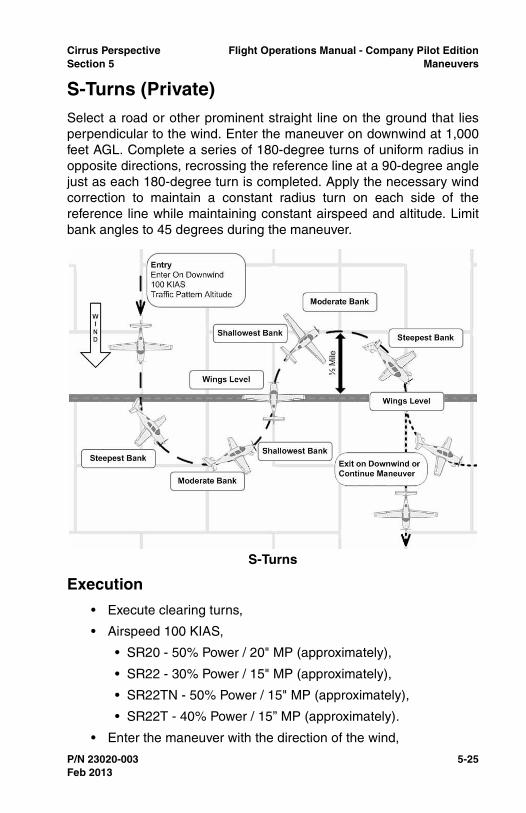
Cirrus Perspective Flight Operations Manual - Company Pilot EditionSection 5 Maneuvers
P/N 23020-003 5-25
S-Turns (Private)Select a road or other prominent straight line on the ground that liesperpendicular to the wind. Enter the maneuver on downwind at 1,000feet AGL. Complete a series of 180-degree turns of uniform radius inopposite directions, recrossing the reference line at a 90-degree anglejust as each 180-degree turn is completed. Apply the necessary windcorrection to maintain a constant radius turn on each side of thereference line while maintaining constant airspeed and altitude. Limitbank angles to 45 degrees during the maneuver.
Execution
• Execute clearing turns,
• Airspeed 100 KIAS,
• SR20 - 50% Power / 20" MP (approximately),
• SR22 - 30% Power / 15" MP (approximately),
• SR22TN - 50% Power / 15" MP (approximately),
• SR22T - 40% Power / 15” MP (approximately).
• Enter the maneuver with the direction of the wind,
S-Turns
Feb 2013
5-26 P/N 23020-003
Flight Operations Manual - Company Pilot Edition Cirrus PerspectiveManeuvers Section 5
• Maintain approximately 1/2 mile radius from the reference line.
Recovery
• Add power as necessary and climb to a desired altitude.
Completion Standards
• Selects a suitable ground reference line perpendicular to thewind,
• Applies adequate wind-drift correction to track a constantradius turn on each side of the selected reference line,
• Reverses the direction of turn directly over the selectedreference line,
• Divides attention between airplane control and ground trackwhile maintaining coordinated flight,
• Maintains altitude, +/-100 feet, airspeed +/-10 KIAS,
• Remains clear of all obstacles or terrain.
Common Errors
• Fails to apply proper rudder inputs to maintain coordinatedflight,
• Fails to clear area for traffic, terrain, or obstacle hazards,
• Over-controls pitch and roll excessively,
• Fails to plan and anticipate wind correction for future segments,
• Displays an inability to quickly scan airspeed and altitudeinstrumentation,
• Over-banks the aircraft and allows an excessive descent rate orsacrifices airspeed causing an accelerated stall condition.
Feb 2013
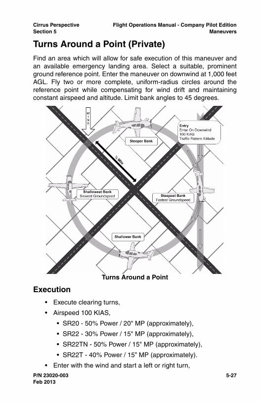
Cirrus Perspective Flight Operations Manual - Company Pilot EditionSection 5 Maneuvers
P/N 23020-003 5-27
Turns Around a Point (Private)Find an area which will allow for safe execution of this maneuver andan available emergency landing area. Select a suitable, prominentground reference point. Enter the maneuver on downwind at 1,000 feetAGL. Fly two or more complete, uniform-radius circles around thereference point while compensating for wind drift and maintainingconstant airspeed and altitude. Limit bank angles to 45 degrees.
Execution
• Execute clearing turns,
• Airspeed 100 KIAS,
• SR20 - 50% Power / 20" MP (approximately),
• SR22 - 30% Power / 15" MP (approximately),
• SR22TN - 50% Power / 15" MP (approximately),
• SR22T - 40% Power / 15” MP (approximately).
• Enter with the wind and start a left or right turn,
Turns Around a Point
Feb 2013
5-28 P/N 23020-003
Flight Operations Manual - Company Pilot Edition Cirrus PerspectiveManeuvers Section 5
• Maintain approximately 1/2 mile radius from reference point.
Recovery
• Add power as required and climb to desired altitude.
Completion Standards
• Selects a suitable ground reference point,
• Plans the maneuver so as to enter a left or a right turn at 1,000feet AGL, at an appropriate distance from the reference point,
• Applies adequate wind-drift correction to track a constantradius turn around the selected reference point,
• Divides attention between airplane control and ground trackwhile maintaining coordinated flight,
• Maintains altitude +/-100 feet, airspeed +/-10 KIAS.
Common Errors
• Fails to apply proper rudder inputs to maintain coordination,
• Fails to anticipate wind conditions for future segments,
• Banks excessively on the upwind segment of the maneuver,
• Fails to adjust pitch control while changing angles of bank,
• Focuses excessively inside the aircraft,
• Fails to scan for traffic during maneuver.
Feb 2013

Cirrus Perspective Flight Operations Manual - Company Pilot EditionSection 5 Maneuvers
P/N 23020-003 5-29
Eight On Pylons (Commercial)Eights on pylons is the most advanced and most difficult of groundreference maneuvers. Because of the various techniques involved,eights on pylons is unsurpassed for teaching, developing, and testingsubconscious control of the airplane.
This training maneuver involves flying the airplane in circular paths,alternately left and right, in the form of a figure “eight” around twoselected points or pylons on the ground. Unlike eights around pylons,however, no attempt is made to maintain a uniform lateral distancefrom the pylon. In eights on pylons, the distance from the pylons variesif there is any wind. Instead, the airplane is flown at such a precisealtitude and airspeed that a line parallel to the airplane’s lateral axis,and extending from the pilot’s eye, appears to pivot on each of thepylons.
Also, unlike eights around pylons, in the performance of eights onpylons the degree of bank increases as the distance from the pylondecreases. The altitude that is appropriate for the airplane being flownis called the pivotal altitude and is governed by the groundspeed.While not truly a ground track maneuver as were the precedingmaneuvers, the objective is similar: to develop the ability to maneuverthe airplane accurately while dividing one’s attention between the flightpath and the selected points on the ground. In explaining theperformance of eights on pylons, the term “wing tip” is frequentlyconsidered as being synonymous with the proper reference line, orpivot point on the airplane. The selected pylons should also be at thesame elevation, since differences of over a very few feet willnecessitate climbing or descending between each turn.
Feb 2013
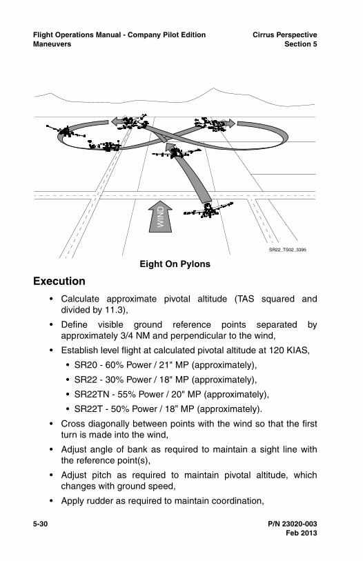
5-30 P/N 23020-003
Flight Operations Manual - Company Pilot Edition Cirrus PerspectiveManeuvers Section 5
Execution
• Calculate approximate pivotal altitude (TAS squared anddivided by 11.3),
• Define visible ground reference points separated byapproximately 3/4 NM and perpendicular to the wind,
• Establish level flight at calculated pivotal altitude at 120 KIAS,
• SR20 - 60% Power / 21" MP (approximately),
• SR22 - 30% Power / 18" MP (approximately),
• SR22TN - 55% Power / 20" MP (approximately),
• SR22T - 50% Power / 18” MP (approximately).
• Cross diagonally between points with the wind so that the firstturn is made into the wind,
• Adjust angle of bank as required to maintain a sight line withthe reference point(s),
• Adjust pitch as required to maintain pivotal altitude, whichchanges with ground speed,
• Apply rudder as required to maintain coordination,
Eight On Pylons
WIN
D
SR22_TS02_3395
Feb 2013
Cirrus Perspective Flight Operations Manual - Company Pilot EditionSection 5 Maneuvers
P/N 23020-003 5-31
• Complete the desired number of figure “eight” circuits aroundthe reference points.
Recovery
• Add power as required and climb to desired altitude.
Completion Standards
• Describes elements related to pivotal altitude,
• Determines the approximate pivotal altitude,
• Enters the maneuver at the appropriate altitude and airspeedand at a bank angle of approximately 30 to 40 degrees at thesteepest point,
• Divides attention between accurate coordinated airplanecontrol and outside visual references,
• Holds pylon using appropriate pivotal altitude avoiding slips andskids.
Common Errors
• Exhibits inadequate knowledge relating to pivotal altitude, and/or ability to visualize maneuver,
• Makes a poor choice of ground reference points,
• Fails to consider surface winds, obstacles, emergency landingareas and/or traffic when defining ground reference points,
• Enters above or below calculated pivotal altitude,
• Uses rudder inputs to position the reference point on the pylon.
Feb 2013

5-32 P/N 23020-003
Flight Operations Manual - Company Pilot Edition Cirrus PerspectiveManeuvers Section 5
Feb 2013
Intentionally Left Blank
Cirrus Perspective Flight Operations Manual - Company Pilot EditionSection 6 Performance
P/N 23020-003 6-1
Section 6Performance
GeneralTo determine what performance to expect from the airplane undervarious ambient and field conditions, Refer to Section 5 - Performance,of the Pilot’s Operating Handbook. Performance data are presented fortakeoff, climb, and cruise (including range & endurance).
Feb 2013

6-2 P/N 23020-003
Flight Operations Manual - Company Pilot Edition Cirrus PerspectivePerformance Section 6
Feb 2013
Intentionally Left Blank
Cirrus Perspective Flight Operations Manual - Company Pilot EditionSection 7 Limitations
P/N 23020-003 7-1
Section 7Limitations
GeneralThe Limitations Section of the Pilot's Operating Handbook (POH) isthe official document approved by the Federal Aviation Administration.It provides operating limitations, instrument markings, basic placardsrequired by regulation, and standard systems and equipment requiredfor safe operation. For amended operating limitations for airplanesequipped with optional equipment, refer to Section 9 - Supplements ofthe Pilot’s Operating Handbook.
Compliance with the operating limitations in Pilot’s OperatingHandbook is required by Federal Aviation Regulations.
Feb 2013

7-2 P/N 23020-003
Flight Operations Manual - Company Pilot Edition Cirrus PerspectiveLimitations Section 7
Feb 2013
Intentionally Left Blank