flexiglass fitting manual - section 1
TRANSCRIPT
LAST UPDATE 30/09/2013 © FLEXIGLASS 2012
FLEXIGLASS FITTING MANUAL - SECTION 1.10A ISUZU D-MAX
FLEXISPORT & WORKSMART CANOPY FIT - ISSA2
MATERIALS & PARTS REQUIRED (FIT KIT 215)
Part No. Description Qty.
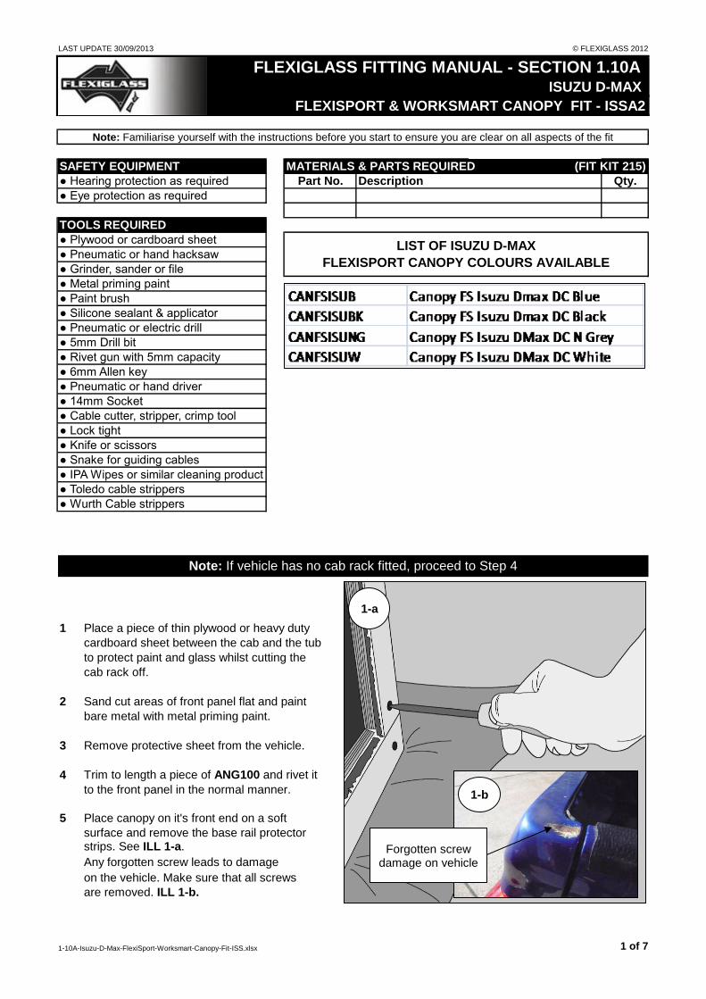
1 Place a piece of thin plywood or heavy duty
cardboard sheet between the cab and the tub
to protect paint and glass whilst cutting the
cab rack off.
2 Sand cut areas of front panel flat and paint
bare metal with metal priming paint.
3 Remove protective sheet from the vehicle.
4 Trim to length a piece of ANG100 and rivet it
to the front panel in the normal manner.
5 Place canopy on it's front end on a soft
surface and remove the base rail protector strips. See ILL 1-a.
Any forgotten screw leads to damage
on the vehicle. Make sure that all screws
are removed. ILL 1-b.
● 5mm Drill bit
● Rivet gun with 5mm capacity
● Silicone sealant & applicator
● Toledo cable strippers
● Knife or scissors
● 6mm Allen key
● Lock tight
● Pneumatic or electric drill
● 14mm Socket
● Cable cutter, stripper, crimp tool
● Wurth Cable strippers
Note: If vehicle has no cab rack fitted, proceed to Step 4
● IPA Wipes or similar cleaning product
Note: Familiarise yourself with the instructions before you start to ensure you are clear on all aspects of the fit
● Plywood or cardboard sheet
● Pneumatic or hand hacksaw
● Grinder, sander or file
● Hearing protection as required
● Eye protection as required
SAFETY EQUIPMENT
TOOLS REQUIRED
LIST OF ISUZU D-MAX
FLEXISPORT CANOPY COLOURS AVAILABLE
● Metal priming paint
● Snake for guiding cables
● Pneumatic or hand driver
● Paint brush
1-a
1-b
Forgotten screw damage on vehicle
1-10A-Isuzu-D-Max-FlexiSport-Worksmart-Canopy-Fit-ISS.xlsx 1 of 7

LAST UPDATE 30/09/2013 © FLEXIGLASS 2012
6 Lift prepared canopy onto tub and position
for best fit.
7 Remove the plastic trim from each canopy
base side rail and retain for future use. See ILL 2.
8 If an over lip liner is fitted holes will need to
be cut in the liner to allow the fitment of the
six clamps. If an underlip liner is fitted
ascertain how stiff the plastic is. If it is too
stiff to allow the clamp to be pushed up
between it and the metal lip, proceed as
follows.
9 Position the clamps so as to miss any ribs
on the liner and if possible missing the
canopy alloy rail securing screws. The front
and rear clamps should be approximately
150mm from their respective rail ends.Note: If the securing screws cannot be
avoided cut a notch in the clamp locating
ridge of the top jaw of the clamp to bridge
them. See ILL 4.
10 Use a 40mm hole saw to cut a hole in the liner so that the top is level with the bottom edge of the coaming lip. Repeat for all six
holes.
11 Fit a clamp at each hole position. See ILL 3.
12 Use a 17mm spanner or socket to pull down
each clamp. Note: Be careful not to over tighten the bolts
as the captive nut can be pulled from it's
housing if tightened over much.
13 Carefully replace the plastic trim to the
bottom rail channel. Cutting it either side of each clamp and each rail bolt. See ILL 5.
2
3
40 mm hole
4
Cut notch here
5 Rail Securing Screw
Cut trim to fit
1-10A-Isuzu-D-Max-FlexiSport-Worksmart-Canopy-Fit-ISS.xlsx 2 of 7

LAST UPDATE 30/09/2013 © FLEXIGLASS 2012
ELECTRICAL WIRE STRIPPING SAFETY PROCEDURE
It is Flexiglass policy that the use of combination electrical cutting/crimping and stripping pliers be
restricted to cutting and crimping use only.
It is a documented fact that the use of these pliers can cause personal injury due to the fact that they
are reliant upon holding the cable in one hand while pulling with the pliers with the opposite hand. Any
attachments to the gripped end can be pulled into and through the palm of the gripping hand causing
injury.
The single hand action strippers are to be used at all times for stripping cable ends ready for joining or
connecting.
Two types of cable strippers are recommended, one operates with the pliers at 90° to the cable (2) the
other operates in-line with the cable (3).
The tool in ILL 2 is a generaly stronger and harder wearing item but the other is very useful for getting
to cables in restricted space, it is therefore recommended that both types be available.
OPERATING INSTRUCTIONS
1 Squeeze handles sufficiently to bring the
lever jaws together. Lay cable between
stripping jaws as shown in ILL 4.
Note:
There should be no necessity to strip more
than 10mm of sheathing from the cable end
for any of the connectors used by Flexiglass.
If for any reason a longer stripped end is
required, do it in repeated 10mm bites, the
pieces can then be slid off the end using
the fingers.
Cutting 1
Crimping
Do not use
2
Toledo brand name
3
Wurth brand name
4 Gripping jaw
Stripping jaw
Lever jaws
1-10A-Isuzu-D-Max-FlexiSport-Worksmart-Canopy-Fit-ISS.xlsx 3 of 7

LAST UPDATE 30/09/2013 © FLEXIGLASS 2012
2 Continue squeezing the handles together to
engage the gripping and stripping jaws.
3 Increase the pressure slightly as you continue
to squeeze. The stripping jaws will then move
indipendantly of the pliers cutting and stripping
the end of the wire until with a sharp click both
sets of jaws will automaticaly disengage.
4 The Wurth pliers are simpler in operation.
After placing the cable in the "V" of the bottom
ILL 7, squeeze the handles together.
The squeezing action brings the jaws together
and forces the bottom jaw forward both cutting
and pulling the sheath from the cable.
See ILL 8 & 9.
5
6
8
9
Bottom jaw moves forward
7 Place in bottom jaw
1-10A-Isuzu-D-Max-FlexiSport-Worksmart-Canopy-Fit-ISS.xlsx 4 of 7

LAST UPDATE 30/09/2013 © FLEXIGLASS 2012
WIRING PROCEDURE
14 Carefully remove, in order, the scuff panel,
kick panel and filler cover lever cowl from the driver side door opening and foot well.
See ILL 6.
15 Approximately 50-75mm in front of the filler
cap lever bracket drill a 20mm hole through
the floor with a hole saw, see ILL 7, and
thread the snap connectors on the end of
the front Flexisport cable harness through,
one at a time.
16 Pass the encased harness through the hole
until the junction point of the relay and the
separate wires is level with the front door
pillar.
17 Locate the brake lamp switch at the rear
of the pedal mount bracket and unplug the
white multi-connector. See ILL 8. Looking
straight up behind the dash board.
18 Loop the blue harness wire up the kick
panel area and arround some cable bundles
to stop it dropping down, then tap it in to the
red wire with pairs of silver bands.
19 Plug the connector back into the switch
body.
20 Locate the multi-connector, see ILL 9, high
up on the right hand wall of the foot well.
21 Run the green (demister switch) wire up
through the vehicle cabling until it can be
tapped into the black/red wire. See ILL 9.
21 A little below this locate a bundle of cables
containing a thick white/black wire.
22 Remove the fuse from the Flexisport fuse
holder then trim the short leg, with the eye
tag connector, long enough to allow the fuse
to be attached to a cable bunch just to the
left of the bonnet catch lever.
6 Scuff panel
Kick panel
Lever cowl
Lever bracket
7 Flexisport harness
Polythene patch
8
To front of vehicle
Brake switch
Red with 2 silver bands
Multi-connector
9 Black/red wire
Engine bay firewall
Green Flexisport wire
Multi-connector
1-10A-Isuzu-D-Max-FlexiSport-Worksmart-Canopy-Fit-ISS.xlsx 5 of 7

LAST UPDATE 30/09/2013 © FLEXIGLASS 2012
23 Tap the trimmed red wire onto the thick
white / black wire. See ILL 10.
24 Tape the fuse holder to the cable bunch
mentioned above and run the long wire with
the female bullet connector over and down
through the wiring to meet it's male
counterpart.
25 Trim off the excess and fit another female
bullet connector to the end, then connect
the two wires.
26 Tap the grey (unlock) wire to the blue wire,
see ILL 11 and the yellow (locking) wire
to the blue / red one. Trim the excess wire
from the connectors.
27 Located behind the wiring, just connected
too, is an earth return. Undo the M6 screw
with a 10mm spanner and attach the
Flexisport earth line under it.
28 Run the canopy harness diagonally across
between the cab rear and the tub front to
meet the front Flexisport harness at the rear
drivers side corner of the cab.
29 Plug the two harnesses together using the
attached connectors and re-fit the fuse to
the demist fuse holder.
30 The canopy harness relay is not a waterproof relay.
We recommend to keep the relay behind the the kick panel ILL 12.
Never place the relay out of the car ILL 13.
31 Test all circuits are functioning correctly.
32 Once all is working, tidy up the wiring behind the kick panel and along the door sill, tape and or tie
where necessary.
33 Apply a liberal bead of silicone sealant arround the hole the front harness passes through in the floor
and place a patch of polythene wrapping film over it to prevent the carpet getting stuck to it. See ILL 7.
34 Replace the carpet and trim panels.
10
Wire to fuse holder
White / black power cable
11
Grey wire goes to blue
Yellow wire goes to blue / red
Tape fuse to wiring up above here
Flexisport earth wire
Canopy Harness Relay
12 13
1-10A-Isuzu-D-Max-FlexiSport-Worksmart-Canopy-Fit-ISS.xlsx 6 of 7

LAST UPDATE 30/09/2013 © FLEXIGLASS 2012
35 Tie the Flexisport harness to the top of the chassis rails, bundle the connectors and excess wire
together and tie them neatly out of the way against the chassis or to some convenient bracket or
crossmember.
36 Clean and detail the canopy ready for delivery to the client.
1-10A-Isuzu-D-Max-FlexiSport-Worksmart-Canopy-Fit-ISS.xlsx 7 of 7