flexible signal generation and analysis for 5g · of wireless communication, ... of bandwidth...
TRANSCRIPT
FEATURE ARTICLE
Enhanced Mobile Broadband (eMBB) is among the possible application sce-narios for the fifth generation of wire-
less communication (5G). Whereas LTE-Advanced Pro presently offers theoretical peak data rates of up to 1.7 Gb/s, 5G aims for peak data rates of 20 Gbps and an aver-age user data rate of hundreds of Mbps. This can only be accomplished by utilizing more bandwidth.
Bandwidths of up to 1 GHz are now under discussion and eventually up to 2 GHz band-widths will be considered. These wide band-widths are not available in the “sweet spot” of wireless communication, which is the fre-quency range between 450 MHz and 6 GHz. Those bandwidths are only available at centi-meter-wave and millimeter-wave frequencies. Based on the discussions at the recent World Radio Conference (WRC) held in November, 2015 in Geneva, Switzerland, the frequency candidates that should be studied for 5G are in the range from 24.25 GHz all the way up to 86 GHz.
Narrowing Down Frequencies for 5G24.25 to 86 GHz is a wide range of fre-
quencies. In July 2016, the U.S. Federal Communicat ion Commission (FCC) announced that it plans to open 10.85 GHz of additional spectrum for 5G. The FCC identified three licensed bands: 28, 37 and 39 GHz. In addition, the FCC identified the
64 to 71 GHz unlicensed frequency band for 5G. It extends the current 60 GHz band now utilized by the 802.11ad standard. The ini-tial priority for local tier-1 carriers in the U.S. is the 28 GHz band, which offers 850 MHz of bandwidth ranging from 27.5 to 28.35 GHz. According to the FCC, the band will be allocated in two blocks offering 425 MHz of bandwidth based on a nationwide license [1].
Competing ProposalsIn parallel to the FCC announcement,
Verizon Wireless, a tier-1 network opera-tor in the U.S., supported by a number of leading infrastructure, chip set and terminal manufacturers, disclosed its own set of tech-nical specifications that describe the physical layer characteristics of a 5G signal [2]. The specified signal is derived from 3GPP’s LTE specification(s) based on Release 12 but has been adapted to be initially used at 28 GHz. The application that will be supported with this standard is fixed wireless access (FWA): in other words, it would support a high-speed Internet connection to the home based on 5G.
The proprietary signal is a multi-carrier signal based on OFDM, using a subcarrier spacing of 75 kHz aiming for a signal band-width of 100 MHz per component carrier. Up to 8 carriers can be aggregated and the basic mode of operation is TDD. The speci-fication defines new synchronization signals,
Flexible Signal Generation and Analysis for 5G
by Andreas Roessler, Technology Manager, North America - Rohde & Schwarz
Rohde & Schwarz, Con’t on pg 46
18 • NOVEMBER 2016 WWW.MPDIGEST.COM

FEATURE ARTICLE
adds new physical channels, and extends and modifies capabilities of existing chan-nels compared to 3GPP’s LTE specification. The goal is to enable beamforming for sig-nal acquisition, tracking, refinement and recovery in order to enable and maintain a connection and to overcome the much higher path loss at higher frequencies. However, the specification has been forged outside the official standardization body, which is the 3rd Generation Partnership Project (3GPP). Table 1 compares cur-rent LTE specification with actual Verizon Wireless 5G specification.
In addition to working with its chip and system vendors, in February 2016 Verizon Wireless announced a partnership with Korean wireless operators Korean Telecom (KT) and South Korea Telecom (SKT) as well as with the Japanese operator NTT DoCoMo. The alliance is called 5G Open Trial Alliance and — as its name implies — the alliance’s goal is to harmonize trials for 5G.
Based on these industry activities, 3GPP adapted its timeline for its version of 5G called “New Radio,” (NR) at its RAN
(Radio Access Network) plenary meeting in June 2016. Initially targeting its Release 15 for a first set of specifications covering NR, 3GPP identified several milestones for the review of the status of PHY/MAC/RLC
layer specifica-tions — and later on the RRC layer.
Based on the use cases formu-lated by the car-riers, there will be a non-standalone (NSA) and a stand-alone (SA) version. NSA will utilize the LTE control plane for signaling. This will enable full m o b i l i t y a n d provide support for the require-ments of Korean a n d J a p a n e s e ope ra to r s fo r their 5G trial ser-vices targeting the 2018 Winter Olympic Games in Pyeongchang, South Korea, and the 2020 Summer Olympic Games in Tokyo, Japan. The SA version will rely exclu-sively on the 5G NR carrier for control informa-tion as well as for data transmis-sion.
At the very same time, 3GPP’s
working group RAN1, which is responsible for physical layer definition, has finished the discussion on the base 5G NR numerology in terms of subcarrier spacing and scaling factors. Scaling is required because at high-er frequencies, the impact of phase noise increases so a higher frequency separation and wider subcarrier spacing is required. To explore this, three different phase noise models were used by RAN1 to determine the performance during link level simula-tions. These models were analyzed for 25, 39 and 70 GHz [3].
Typical frequencies 3GPP RAN1 uses for its simulations, including numerology parameter, are 30 and 70 GHz. After some debate in RAN1, the working assumption is to continue for subcarrier scaling with a base frequency of f0 and a scaling fac-tor of 2m. For backward compatibility, 15 kHz, the subcarrier spacing in LTE, was selected as base frequency. The exponent m can take values of {-2, 0, 1, …, 5} and thus subcarrier spacings of 3.75 kHz and 15, 30, …, 480 kHz are considered. Based on this agreement, a 75 kHz subcarrier spacing is not supported by 3GPP RAN1, which is contradictory to the Verizon Wireless 5G specification.
For now, there are two competing ways to realize the physical layer from a subcarri-er spacing point of view. Nonetheless, there are still many issues to be resolved regard-ing 3GPP’s RAN1 compared to the Verizon Wireless specification. For instance, dif-ferent Cyclic Prefix lengths per subcarrier spacing will be studied, where these cyclic prefixes can have substantially different lengths. In addition, the number of sub-carrier per physical resource block (PRB), which is 12 in LTE, is currently under inves-tigation and should be decided at the next meeting, which takes place in November 2016.
Rohde & Schwarz, Con’t on pg 48
Rohde & Schwarz, Con’t from pg 18
Table 1: Comparing LTE PHY parameter with Verizon Wireless 5G parameterization
PowerDivision
Freq. Range(GHz)
Insertion Loss (dB)
Isolation(dB)
AmplitudeBalance
ModelNumber
2 1.0-27.0 2.5 15 0.5 dB PS2-512 0.5-18.0 1.7 16 0.6 dB PS2-20
5-40 GHz 1-5 GHz2 1.0-40.0 2.8 13 10 0.6 dB PS2-552 2.0-40.0 2.5 13 0.6 dB PS2-542 15.0-40.0 1.2 13 0.8 dB PS2-532 8.0-60.0 2.0 10 1.0 dB PS2-562 10.0-70.0 2.0 10 1.0 dB PS2-573 2.0-20.0 1.8 16 0.5 dB PS3-514 1.0-27.0 4.5 15 0.8 dB PS4-514 5.0-27.0 1.8 16 0.5 dB PS4-504 0.5-18.0 4.0 16 0.8 dB PS4-174 2.0-18.0 1.8 17 0.5 dB PS4-194 15.0-40.0 2.0 12 0.8 dB PS4-528 0.5-6.0 2.0 20 0.4 dB PS8-128 0.5-18.0 7.0 16 1.2 dB PS8-168 2.0-18.0 2.2 15 0.6 dB PS8-13
���WR����ZDWWV�SRZHU�KDQGOLQJ��YLVLW�ZHEVLWH�IRU�FRPSOHWH�VSHFLÀFDWLRQV�SMA and Type N connectors available to 18 GHz.
46 • NOVEMBER 2016 WWW.MPDIGEST.COM
FEATURE ARTICLE
Implications for 5G Signal Generation and Analysis
Based on the standardization options dis-cussed so far and the ideas put forward by an industry alliance (whose members also contribute to the standard organization), the question is: What does it all mean in terms of test and measurement solutions? The answer is simple: flexibility!
Offering signal generation and signal analysis solutions for 5G is particularly challenging and requires both advanced expertise and a knack for innovation. Spectrum analyzers, for example, must be able to handle frequencies up to and beyond 71 GHz. They must also accommodate numerous variants and offer an extensible analysis bandwidth. Similarly, signal gen-erators must be capable of handling high frequencies and be extensible.
The R&S FSW signal and spectrum analyzer, for example, offers frequency variants including 43.5 GHz, 67 GHz, all the way up to 85 GHz. The instantaneous bandwidth is 512 MHz. This analysis band-width can be easily extended up to 2 GHz with the innovative utilization of the R&S RTO2044 Digital Oscilloscope as an exter-nal digitizer. 5G presents similar challenges for signal generators. The R&S SMW200A Vector Signal Generator, for example, sup-ports frequencies up to 40 GHz in a single instrument and offers up to 2 GHz internal modulation bandwidth. Its frequency range can be extended with the newly released R&S SZU up-converter, intended for test-ing 802.11ad that supports frequencies between 57 and 66 GHz.
The signal generator must also have the built-in flexibility to support testing multiple waveforms. 5G waveform candi-dates include UFMC, FBMC, GFDM and f-OFDM. When 5G research picked up early 2015, Rohde & Schwarz responded by adding signal generation capabilities to its R&S SMW200A via a software option. In addition, an extension to its FS-K96 OFDM Vector Signal Analysis Software makes it possible to analyze generic OFDM-based signals and also other waveform candidates such as GFDM and UFMC. A detailed description of these waveforms, a comparison with LTE as a pure OFDM-based waveform and how to use Rohde & Schwarz signal generation and analysis solutions can be found in an R&S applica-tion note [5].
Ease of UseEase of use is an important consideration
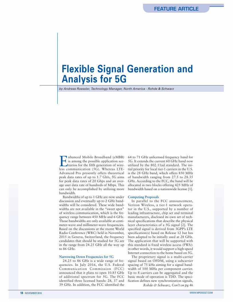
when choosing instruments for testing 5G signals. Software options are the key to achieving fast, accurate measurements in just a few steps. For example, using soft-ware option K114 on the SMW200A signal generator, it is possible to generate generic OFDM signals. The user simply defines key parameters for OFDM such as the FFT size, the number of occupied subcar-rier Cyclic Prefix lengths, and the sequence length in the form of the number of OFDM symbols. By applying the correct settings, the user can derive, for example, a Verizon Wireless-like 5G signal (see Figure 1) or emulate the parameter settings that are cur-
rently being discussed in 3GPP RAN1 for 5G NR at least for the basic physical layer parameters.
In the allocation tab, the user simply defines different allocations that could be either used for pilot sequence or for user data. For the user data allocations, differ-ent modulation schemes could be used, all the way up to 256QAM.
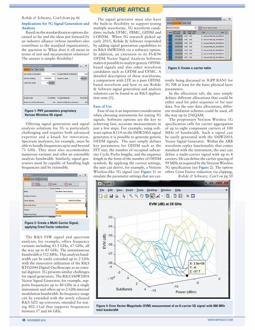
The proprietary Verizon Wireless 5G specification calls for carrier aggregation of up to eight component carriers of 100 MHz of bandwidth. Such a signal can be easily generated with the SMW200A Vector Signal Generator. Within the ARB waveform replay functionality that comes standard with the instrument, the user can define a multi-carrier signal with up to 8 carriers. He can define the carrier spacing of 99 MHz as required by the Verizon Wireless 5G specification (see Figure 2). The option offers Crest Factor reduction via clipping,
Rohde & Schwarz, Con’t on pg 50
Rohde & Schwarz, Con’t from pg 46
Figure 1: PHY parameters proprietary Verizon Wireless 5G signal
Figure 2: Create a Multi-Carrier Signal, applying Crest Factor reduction
Figure 3: Create a carrier table
Figure 4: Error Vector Magnitude (EVM) measurement of an 8-carrier 5G signal with 800 MHz total bandwidth
48 • NOVEMBER 2016 WWW.MPDIGEST.COM

FEATURE ARTICLE
which optimizes the signal if the individual signals are OFDM-based and thus have a high peak-to-average power ratio.
In the tab “Carrier Table” (see Figure 3) the user can now define each of the 8 carri-ers individually. Each carrier is defined by a waveform file that could be generated with software option K114.
The offset from selected carrier frequen-cy (i.e., 28 GHz) is determined from the carrier spacing defined earlier and applied automatically. For each carrier, a certain gain, phase or delay can be applied, creat-ing more realistic test scenarios.
Those signals could be used today for component characterization, such as a newly designed power amplifier opera-tional at 28 or 39 GHz, targeting 5G base station and access points. Figure 4 shows a measurement of such a signal to determine signal quality with help of an Error Vector Magnitude (EVM) measurement during a power level sweep from -15 to 0 dBm. The average EVM is about -36.0 dB.
For the signal analysis side, signal
analysis software can provide the required flexibility to analyze generic OFDM-based sig-nals. For example, the FS-K96 soft-ware installed on an external PC and connected to the R&S FSW Signal a n d S p e c t r u m Analyzer can cap-ture IQ data from the spectrum ana-lyzer, post pro-cess the captured data and display the results such as power spectrum, constellation dia-gram, EVM vs. subcarrier and/or symbol and many more.
A few things need to be config-ured within the software to start creating a con-figuration file that allows the user to demodulate the desired signal and conduct on EVM and other signal qual i ty param-eters. First, the correct sampling frequency needs to be set under “General Settings”
(Figure 5). Second, in the section “Demod Settings,” the FFT size needs to be defined as well as Cyclic Prefix length. In case there is no Cyclic Prefix (CP), a Preamble must be embedded in the signal and the user needs to apply the correct parameterization for
that preamble (Figure 6). Cyclic Prefix or Preamble are essential, as the software is using these signal components to do the time synchronization. For the CP, different CPs for different symbols can be config-ured. LTE already makes use of this capa-bility: For the normal CP mode, the very first OFDM or SC-FDMA symbol uses a longer CP than the remaining 6 symbols in the time slot.
After applying these basic settings, the user can capture the signal via RF from a connected vector signal generator, such as the SMW200A, for example. Alternatively, an arbitrary (ARB) waveform file can be loaded directly into the software. Rohde & Schwarz recommends starting with the ARB file as this “ideal” IQ data is not com-promised by the analog components of the instruments while being IQ modulated, up-converted, amplified, down-converted and demodulated. The results would also represent the best possible, ideal EVM for the configured signal. After everything is configured correctly, the configuration file wizard can be started by clicking the “Generate Configuration File” button in the menu. The IQ data is loaded into the
Rohde & Schwarz, Con’t from pg 48
Figure 6: Definition of Cyclic Prefix length(s) according to Verizon Wireless 5G specification
Figure 7: FS-K96 Configuration File Wizard
Figure 5: Set frequency and sampling rate
Rohde & Schwarz, Con’t on pg 55
50 • NOVEMBER 2016 WWW.MPDIGEST.COM
FEATURE ARTICLE
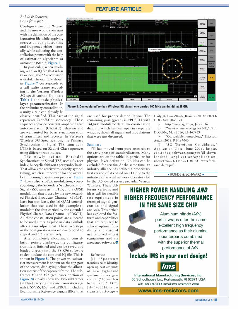
Configuration File Wizard and the user would then start with the definition of the con-figuration file while applying correction for phase, time and frequency either manu-ally while adjusting the con-stellation points with the help of estimation algorithm or automatic (Step 3; Figure 7).
In particular, when work-ing with an IQ file that is less than ideal, the “Auto” button is useful. The example shown in Figure 7 corresponds to a full radio frame accord-ing to the Verizon Wireless 5G specification: Compare Table 1 for basic physical layer parameterization. In the preliminary constellation, a unity circle can already be clearly identified. This part of the signal represents Zadoff-Chu sequence(s). These sequences provide constant amplitude zero autocorrelation (CAZAC) behavior and are well suited for basic synchronization of transmitter and receiver. In Verizon’s Wireless 5G Specification, the Primary Synchronization Signal (PSS; same as in LTE) is based on Zadoff-Chu sequences using different root indices.
Th e n ew ly d e f i n ed Ex t en ded Synchronization Signal (ESS) uses a fix root index, but cyclic shifts on a per symbol basis. That allows the receiver to identify symbol timing, which is important for the overall beamforming acquisition process. Figure 7 shows also a BPSK modulation, corre-sponding to the Secondary Synchronization Signal (SSS, same as in LTE), and a QPSK modulation that is used by the new, extend-ed Physical Broadcast Channel (xPBCH). Last but not least, the 16 QAM constel-lation that was used in this example to modulate the data carried by the extended Physical Shared Data Channel (xPDSCH). All these constellation points are allocated to be used either as pilot or data symbols after a gain adjustment. These two steps in the configuration wizard correspond to steps 4 and 5/6, respectively.
After completely allocating all constel-lation points displayed, the configura-tion file is finished and can be saved and loaded directly into the FS-K96 software to demodulate the captured IQ file. This is shown in Figure 8. The power vs. subcar-rier measurement is shown on the top part of the screen, displaying below the alloca-tion matrix of the captured frame. The sub-frames #0 and #25 (see lower portion of Figure 8) clearly show the two subframes (in blue) carrying the synchronization sig-nals (PSS/SSS, ESS) and xPBCH, including Beamforming Reference Signals (BRS) that
are used for proper demodulation. The remaining part (green) is xPDSCH with 16QAM modulated data. The constellation diagram, which has been open in a separate window, shows all signals and modulations that were just discussed.
Summary5G has moved from pure research to
the early phase of standardization. Many options are on the table, in particular for physical layer definition. No idea can be excluded for certain. At the same time, an industry alliance has defined a proprietary first version of 5G based on LTE due to the initiative of several network operators led by the U.S.-based service provider Verizon Wireless. These dif-ferent versions and ideas call for flexible test equipment in terms of signal gen-eration and signal analysis. This article has explored the fea-tures and capabilities that are required to achieve optimal flex-ibility and ease of use required in test equipment and its associated software.
References[1] “ S p e c t r u m
frontiers rules identify, open up cast amounts of new high-band spectrum for next gen-eration (5G) wireless broadband,” FCC, July 14, 2016, http://t rans i t ion . fcc .gov /
Daily_Releases/Daily_Business/2016/db0714/DOC-340310A1.pdf
[2] http://www.5gtf.org/, July 2016[3] “Views on numerology for NR,” NTT
DoCoMo, May 2016, R1-165439 [4] “On scalable numerology,” Ericsson,
August 2016, R1-167040 [5] “5G Wave form Cand ida te s ,”
Application Note, June 2016, https://cdn.rohde-schwarz.com/pws/dl_down-l o a d s / d l _ a p p l i c a t i o n / a p p l i c a t i o n _notes/1ma271/1MA271_0e_5G_waveform_candidates.pdf
Include IMS in your next design!
International Manufacturing Services, Inc.���:JOVVSOV\ZL�3U���7VY[ZTV\[O��90�������<:(
�������� ������PTZ'PTZ�YLZPZ[VYZ�JVT
www.ims-resistors.com
(S\TPU\T�UP[YPKL��(l5��WHY[PHS�^YHWZ�VMMLY�[OL�ZHTL�L_JLSSLU[�OPNO�MYLX\LUJ`�
WLYMVYTHUJL�HZ�[OLPY�HS\TPUH�JV\U[LYWHY[Z�JVTIPULK�^P[O�[OL�Z\WLYPVY�[OLYTHS�WLYMVYTHUJL�VM�(l5�
HIGHER POWER HANDLING AND HIGHER FREQUENCY PERFORMANCE
IN THE SAME SIZE CHIP
• ROHDE & SCHWARZ •
Figure 8: Demodulated Verizon Wireless 5G signal, one carrier, 100 MHz bandwidth at 28 GHz
Rohde & Schwarz,Con’t from pg 50
NOVEMBER 2016 • 55WWW.MPDIGEST.COM