flameboyant - pivot stove · flue spigot: natural draught flue system using 2 Ø150 ~ 200 twin skin...
TRANSCRIPT

Gas Fire Installation Guide
Installation into Timber Framing
illusion 1800
Retain these instructions until installation is complete
FlameboyantBy Real Fires
�
IMPORTANT NOTES:
THIS APPLIANCE MUST BE INSTALLED BY A SUITABLY QUALIFIED PERSON IN ACCORDANCE WITH LOCAL CODES AND AS 5601 / NZS 5�61
THIS IS PRIMARILY A DECORATIVE APPLIANCE AND HAS NOT BEEN DESIGNED AS A SPACE HEATER
THIS APPLIANCE HAS BEEN TESTED TO AS 4558-�000
DO NOT OPERATE THIS APPLIANCE WITHOUT READING AND UNDERSTANDING THESE INSTRUCTIONS FIRST
THIS APPLIANCE IS DESIGNED FOR INSTALLATION INTO A TIMBER FRAMED CONSTRUCTION
THIS APPLIANCE MUST INSTALLED USING AN APPROVED TWIN SKINNED B-VENT FLUE SYSTEM
THIS APPLIANCE MUST BE INSTALLED INTO A WELL VENTILATED ROOM IN ACCORDANCE WITH AS 5601/ NZS 5�61
THIS APPLIANCE IS DESIGNED FOR INDOOR INSTALLATION ONLY; NOT TO BE INSTALLED OUTDOORS
REAL FIRES IS NOT RESPONSIBLE FOR INCORRECT OR IMPROPER INSTALLATIONS
ALL INSTALLATIONS MUST BE CERTIFIED
BE SURE TO FILL IN INSTALLER DETAILS SECTION OF THE USER GUIDE BEFORE SIGNING OFF THE INSTALLATION
Some drawings in this guide use a smaller version of this fire for pictorial purposes only.

�
IMPORTANT NOTES: �Specifications: 4Notes on Installation: 5 Gas Supply 5 Electrical Supply 5 Clearances 5 Hearths 5 Mantles and Recesses 5 Flue requirements 6Firebox installation: 6 Options 6 Insulation kit fitting 6 Framing requirements 7 Top Fixing 8 Wall Lining 9Commissioning: 9 Remove reflectors 10 Remove Burner 10 Connect Gas 10 Prepare for testing 10 Check Pressures 10 Reassemble 10 Final Checks 10Wiring Diagram 10Trouble Shooting 11Installation Notes 11
Contact Details 1�
Table of Contents

4
Specifications:
Make: FlameboyantModel: illusion 1800Gas Types: Natural Gas, ULPG, Propane (Australia only)Description: Indoor Decorative FireTest standards: NZS 5262:2003, AS 4558-2000 AS/NZS 3100:2002
Approval No: 77�6Dimensions: All dimensions are in mm Note: Left hand version of fire shown, right hand version available if required
Flue Spigot: Natural draught flue system using 2 Ø150 ~ 200 twin skin flue with optional adaptor to single Ø200 ~250 twin skin flue (inner flue to be stainless steel) Minimum of 2.4 metres of flue, 3.6 metres if off-set bends are usedFlue Cowl: two approved 150 mm or one �00 mm Flue Cowls must be used Gas Connection: �/8” BSPF Gas Flare onto gas controlPower: 230/240V a.c. 50hz, 1 Amp Natural gas ULPG/Propane Inlet Pressure: 1.0 kPa 2.75 kPa Burner Pressure: 0.8 kPa 1.9 kPa Gas Rate: �4 MJ/h �4 MJ/h Main Injector: Ø 3.0 mm Ø 1.8 mm Aeration None Ø 10.00 mm Gas Control: SIT 840 with SIT 579. 402 DBC Ignition: Electronic
Flame Monitoring: Flame rod
Control: Isolating switch
210
453
2174
1825
1469469
Gas Inlet
PowerInlet
50
260297

5
Notes on Installation: All notes refer to left hand version of fire and must be reversed if a right hand version is being installed
Gas Supply A suitable gas supply needs to be provided to the Left hand rear corner of the installation cavity. The pipe sizing should be calculated to supply at least 40 MJ/hAllow sufficient pipe to make the connection as shown below (Refer to the Commissioning section for details on gas and power connection, page 10)
Electrical SupplyThe Firebox is supplied with a power lead approx. 1.8 m long. This needs to be connected to an isolating wall switch, provided by an electrician, located preferably to the right of the Firebox, facing into the room, not inside the framing cavity. This supply is used to isolate all power for the electronic fires or to control the fan in the manual fires. Note: if the power is disconnected through power cut or other event and reinstated with the isolating switch in the ON position, the fire will start automatically. To prevent this it is recommended that a latched relay is used as shown here.
The power cord is designed for a 230/240V a.c. 10 amp supply. Electrical connection must comply with AS/NZS 3000.
ClearancesThe fire must be installed with the shown minimum clearances to combustible materials
HearthsAlthough a hearth is not required, if the fire is installed within 500 mm of the floor, Real Fires does recommend that protection is given to any combustible flooring directly in front of the fire. The fire produces a large amount of radiant heat and this might cause damage to carpets and furnishings that are too close.
Mantles and RecessesA timber mantle may be installed above this appliance but must be within the grey area shown here. If the fire is to be installed into a recess the recess must comply with the following limitations
Note: The same limitations apply to the sides of the fire
This bend is required to clear gas control Open Side
Glass Side
103
±5
400 ±10
approx
Power lead 1.8 Metres
NCCOMMON
10 Amp Relay
NO
P
N
E
To Fire/s
Mai
ns S
uppl
y
500 mm Min10
00 m
m
Min
500 mm
Min
1000 mmMin
300
X
X
45°
Top Trim
Mantle
Wal
l
Mantle must not extend beyondthis area
100
45°
Fire Proof Board
Fire Proof Board for minimum height of 300mm
Recess must notextend beyond this area

6
Flue requirementsOnly used an approved cowl The fire is fitted with two Ø150~200 flue spigots and standard flue components should be used. A Y piece collector is available from Real Fires that allows the two flues to be joined into one Ø200~250 to be finished using standard twin skin flue and flue cowl. It is recommended that the 150~200 mm flue is taken vertically as high as practicable before joining using the Y piece. The minimum total flue height is 2.4 metres, providing the flue is straight without offsets.Offsets can be used on flues over 3.6 metres in height. The flue and cowl must be installed in accordance with AS 5601/NZS5261
Firebox installation:Options The illusion fire can be installed in 4 different ways. The basic fire is supplied ready for installation as a fully open fire where the fire is open to the front and the glass sides are to the right and back. It is also available as a right hand fire if required. The installations options are:
Cut here forThrough Wall andFully Enclosed Cut here for
Through Wall andCorner Unit
Relieve corner of unseen trim to allow wall lining to fit behind the trim
DO NOTCUT THE SEENTRIM PANELS
Align facesand edges
Drill and rivetin place (4 places)
Fully Open (left hand version) Corner Unit
Fully Enclosed Through Wall
Note: All fires are shown with the open side foremost and glass panels to the back and right hand end. Even with the insulation kits installed, the glass panels remain in place.
Insulation kit fittingInsulation kits are available for conversion these options and will require fitting before the installation continues. Unseen trims may need to be cut away to make fitting of the wallboard easier and tidier, the trims to cut will depend on the installation option. Make sure that you have clearly identified the panels that are to be cut before proceeding. It may be easier to fit the insulation panel prior to making any cuts. Be sure to remove all the protective plastic from any panels that will be covered by the insulation panels.

7
Framing requirementsThe following diagrams show the framing requirements for each installation type. Notes: The flue and firebox must be installed before the wall can be lined. The framing must be self supporting and not place any load on the firebox. The flue system must also be supported and not placing load on the firebox. The framing shown is indicative only is not intended to illustrate the construction method. All installations are shown with 1 length of rectangular flue and the rectangular to round adapter and does not represent a complete installation. It is recommended that the fire is installed on a solid platform but is not a requirement Gas and power supply must enter through the left hand end of the firebox The Wall lining above the fire must be non combustible for a minimum off 300 mm above the top trim
There must be a clearpath for the flue to pass
Refer tonote ontop fixing
Flue is shown with optional fluegather and 200~250mm top fluesection. Alternative is to run twoflues throught to termination
Platformrecommended
Allow at least20mm gap forpower and gas
These sections must be fullysupported from above andnot place any load on the fire
Min
463
250
Min
imum
Rec
omm
ende
d10
00
min over295
cladding
1000
715 Min
Min 468 overcladding
2183 Min
Wall lining above the top trim must be non-combustible for at least 300mm (wall lining can only be fitted after firebox is installed)
Fully Open installation
Corner installation
Refer tonote ontop fixing
Flue is shown with optional fluegather and 200~250mm top fluesection. Alternative is to run twoflues through to termination
There must be a clearpath for the flue to pass
Platformrecommended
Allow at least20mm gap forpower and gas
over
Min250
min
imum
reco
mm
ende
d10
00
1000
cladding
Min715
over Min
Min
463 Min
2183
cladding
468322 Min
263 Min
Wall lining above the top trim must be non-combustible for at least 300mm (wall lining can only be fitted after firebox is installed)

8
Fully Enclosed installation
There must be a clearpath for the flue to pass
Refer tonote ontop fixing
Flue is shown with optional fluegather and 200~250mm top fluesection. Alternative is to run twoflues through to termination
Platformrecommended
Allow at least20mm gap forpower and gas
1000
min
imum
reco
mm
ende
d
Min
Min
463
cladd
ing495 Min
1000
overMin
Min715
Min250
322
2210
263 min
Wall lining above the top trim must be non-combustible for at least 300mm (wall lining can only be fitted after firebox is installed)
Top FixingIn order to keep the top, unsupported end of the firebox in line with the framing above, a pair of straps have been provided for fixing to the completed framing. In some installations the straps may not be the most suitable solution. If this is the case then use another seismic type strap to hold the firebox fast to the framing. Take care to make sure that the wall cladding will line up with the inside edge of the trim panel.Shown here is the cutout requirement for the straps to be most effective.
Seismic RestraintThere are 4 holes in the base of the firebox to hold the fire in place. Make sure that the firebox is correctly aligned with where the wall lining will finish before fixing the firebox in place.
Through Wall installation
Refer tonote ontop fixing
Flue is shown with optional fluegather and 200~250mm top fluesection. Alternative is to run twoflues throught to termination
Platformrecommended
Allow at least20mm gap forpower and gas
This section must be fullysupported from above andnot place any load on the fire
2210 Min
min
imum
495 Min
1000
1000
Min250
reco
mm
ende
d
Min715
295 Minovercladding
There must be a clearpath for the flue to pass
Wall lining above the top trim must be non-combustible for at least 300mm (wall lining can only be fitted after firebox is installed)
from cladding to back of support plate
21
115 Min
9
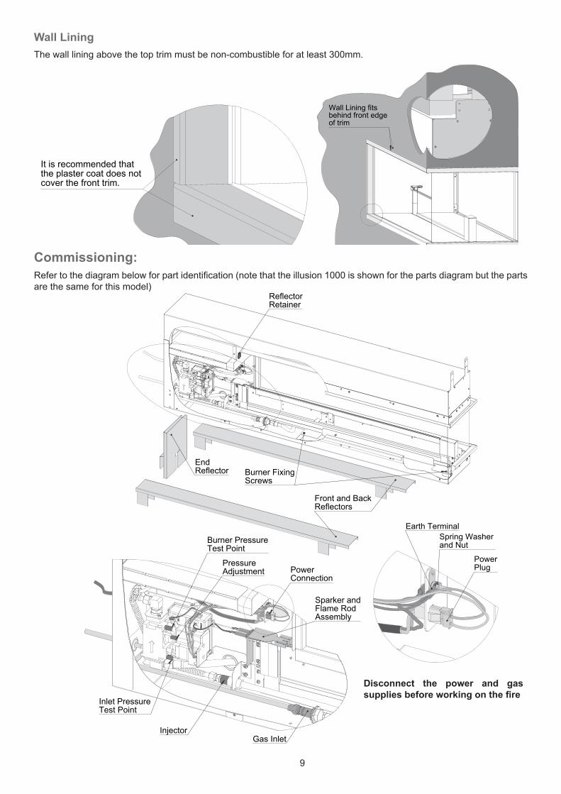
of trim
Wall Lining fitsbehind front edge
It is recommended thatthe plaster coat does not cover the front trim.
Wall LiningThe wall lining above the top trim must be non-combustible for at least 300mm.
Commissioning:Refer to the diagram below for part identification (note that the illusion 1000 is shown for the parts diagram but the parts are the same for this model)
Burner PressureTest Point
Inlet PressureTest Point
Injector
Sparker andFlame RodAssembly
PressureAdjustment
Gas Inlet
PowerConnection
ReflectorRetainer
EndReflector
Front and BackReflectors
Burner FixingScrews
PowerPlug
Earth TerminalSpring Washerand Nut
Disconnect the power and gas supplies before working on the fire

10
Remove reflectorsTo gain access to the burner, power, and gas connections, firstly rotate the Reflector Retainer upwards to release the top of the end reflector and remove the reflector. Remove the right hand end burner cover by carefully lifting straight up.Slide the front reflector towards the gas control enough to gain purchase on both ends of the reflector and remove it. Remove the 2 screws holding the burner in place and slide the burner forward to gain access to the rear reflector and remove the reflector.Push the burner assembly as far back as possible without crushing the gas supply hose or wires etc.
Remove BurnerIf it is necessary to remove the burner assembly then carefully unscrew the flexible braided hose from the gas inlet connection and remove the earth lead from the power bracket and unplug the power connector. Carefully lift the burner out of the cavity.
Connect GasBend the Gas supply tube as shown on page 5, flare and fit to inlet connection. Check for any crimps or kinks in the braided hose. Reconnect the gas and check for leaks.
Prepare for testingMake sure that any protective plastic has been removed from any panels likely to be affected by staring the fire.
Check PressuresWith the burner connected and pushed to the back of the firebox, connect a manometer to the burner pressure test point. Connect the power supply and switch the fire on. The spark ignition will start within a few seconds and the burner will ignite. If the burner fails to ignite within about 5 seconds, the spark will stop and the gas will cease to flow. It may take several attempts to get the burner to ignite especially with a new gas installation. Restart the fire by turning the switch off, waiting a couple of seconds, and switching back on.Adjust the burner pressure by removing the protective cap from the adjusting stem and adjusting the regulator beneath. Check pressure against the data plate.Turn the fire off and remove the manometer and tighten the test point.
ReassembleReplace all panels and reflectors previously removed, make sure that the burner is fastened in place and any remaining protective plastic has been removed.
Final ChecksWith all panels in place, check to make sure that the fire is still operating correctly and that the flames are not overly long or streaky and that there is no soot coming from the flame tips. Listen for excessive noise when the fire is igniting or extinguishing. Be sure to fill in the Installation section of the User Guide and explain the operation of the fire to the owner
Wiring Diagram
121
SPARK
FLAME
GAS CONTROL(SIT840 with 0.579.402 DBC)
WH (HT LEAD)
GR
OR
2 - E
MP
TY1
- EM
PTY
4 - E
MP
TY
8 - E
MP
TY9
- EM
PTY
10 -
BR
N11
- B
LU12
- G
R
3 - E
MP
TY
7 - B
LK6
- BLK
5 - B
LK
MAINS IN230/240 V a.c.50 Hz10 AMP MAX
GAS CONTROL 12 PIN PLUG
GR
BLU
BRN
GR85
5 Amp
Connector Plug
COLOUR
WH WHITEBLU BLUEBRN BROWNGR GREEN / YELLOWOR ORANGE

11
Trouble Shooting
Installation NotesWrite any comments on the installation here and leave with the owner for future reference.
Problem Possible Cause RemedyFire does not start (no spark noise)
Mains Power Disconnected Check mains supply and isolating switchGas Control locked out Switch Off and On again *Faulty Spark Electrode Check HT lead
Check Electrode is not touching the bracketFaulty control Service call
Fire is sparking then stops (no flames)
Air in gas pipe Purge gas pipes *Gas supply turned off/empty Turn on gas supply or change bottles *
Flame starts but spark keeps going
Faulty flame rod Check flame rod lead Check flame rod is not touching the bracket
Wind blowing on burner Prevent excessive draft on burnerSpark going but flames don’t appear to go out
Faulty flame rod Check flame rod lead Check flame rod is not touching the bracket
Wind blowing on burner Prevent excessive draft on burnerFire goes out Gas Supply turned off or empty Check gas supply or change/replace bottles
Power supply turned off Check power is onWind blowing on burner Prevent excessive draft on burner
* If the fire fails to ignite after 3 attempts, turn off the power and gas if possible and arrange a service call or contact the installer if fire is new.

12
Contact Details
66300
issue D
Installation Guide illusion 1800
Flameboyant.com.au
Regency Fireplace Products Australia Pty Ltd.
21-23 South Link
Dandenong
South Vic 3175
Australia
Phone 1 800 081 978
Fax 03 9799 7822
Email [email protected]