fisher vee‐ball v150, v200, and v300 rotary control valves ... · instruction manual d101554x012...
TRANSCRIPT
www.Fisher.com
Fisher™ Vee‐Ball™ V150, V200, and V300 RotaryControl Valves NPS 1 through 12
ContentsIntroduction 1. . . . . . . . . . . . . . . . . . . . . . . . . . . . . . . . .
Scope of Manual 1. . . . . . . . . . . . . . . . . . . . . . . . . . . . .Description 2. . . . . . . . . . . . . . . . . . . . . . . . . . . . . . . . .Specifications 2. . . . . . . . . . . . . . . . . . . . . . . . . . . . . . .Educational Services 2. . . . . . . . . . . . . . . . . . . . . . . . . .
Installation 3. . . . . . . . . . . . . . . . . . . . . . . . . . . . . . . . . . . .Maintenance 8. . . . . . . . . . . . . . . . . . . . . . . . . . . . . . . . . .
Packing Maintenance 8. . . . . . . . . . . . . . . . . . . . . . . . .Replacing the Ball Seal 11. . . . . . . . . . . . . . . . . . . . . . .
Disassembly 11. . . . . . . . . . . . . . . . . . . . . . . . . . . .Assembly 14. . . . . . . . . . . . . . . . . . . . . . . . . . . . . .HD Ball Seal Lubrication 20. . . . . . . . . . . . . . . . . .
Bearing and Ball Maintenance 20. . . . . . . . . . . . . . . . .DN80 - 300 (NPS 3 - 12) valves 20. . . . . . . . . . . . . . . .
Welded Taper Key Replacement 24. . . . . . . . . . .DN25 - 50 (NPS 1 - 2) valves 25. . . . . . . . . . . . . . . . . .
Cavitrol™ Hex Installation 32. . . . . . . . . . . . . . . . . . . . . .Actuator Mounting 32. . . . . . . . . . . . . . . . . . . . . . . . . . . .NPS 3 - 12 without Attenuator 33. . . . . . . . . . . . . . . . . .
Determining Mounting Position 33. . . . . . . . . . . . . . .Determining Closed Position 33. . . . . . . . . . . . . . . . .
Parts Ordering 40. . . . . . . . . . . . . . . . . . . . . . . . . . . . . . . .Parts Kits 42. . . . . . . . . . . . . . . . . . . . . . . . . . . . . . . . . . . . .Parts List 44. . . . . . . . . . . . . . . . . . . . . . . . . . . . . . . . . . . . .Appendix A Instructions for Non‐Series B 45. . . . . . . . .
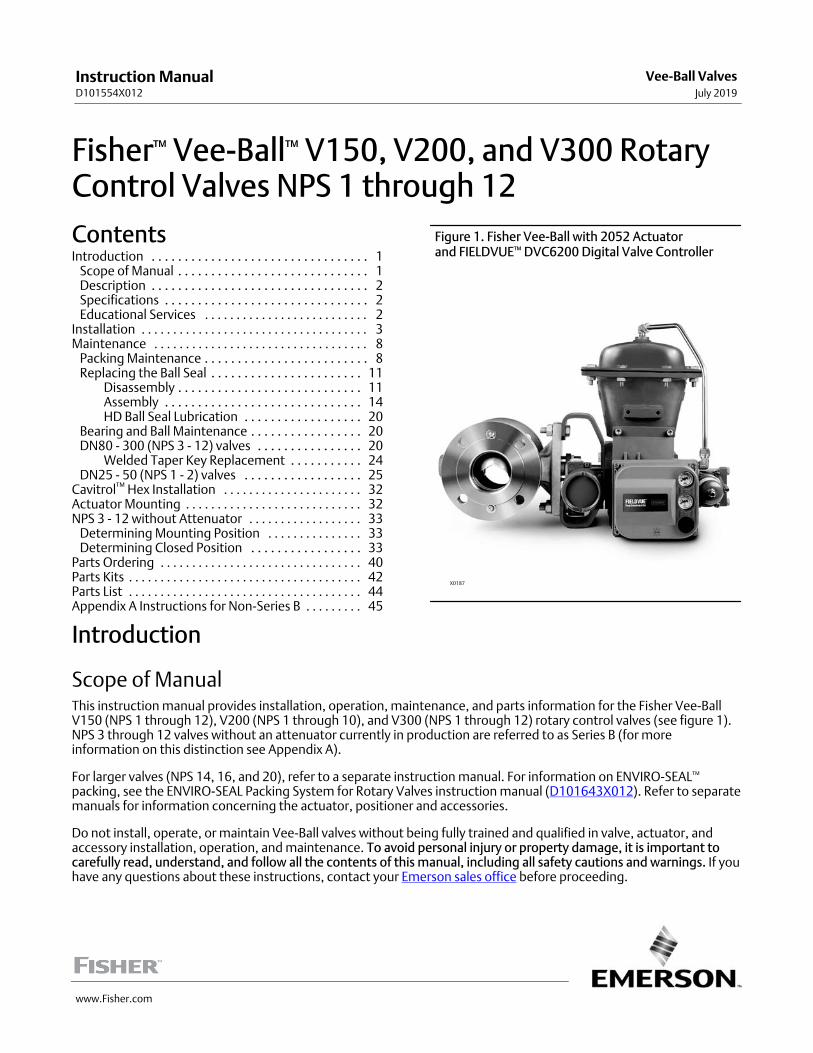
Figure 1. Fisher Vee‐Ball with 2052 Actuator and FIELDVUE™ DVC6200 Digital Valve Controller
X0187
Introduction
Scope of ManualThis instruction manual provides installation, operation, maintenance, and parts information for the Fisher Vee‐BallV150 (NPS 1 through 12), V200 (NPS 1 through 10), and V300 (NPS 1 through 12) rotary control valves (see figure 1).NPS 3 through 12 valves without an attenuator currently in production are referred to as Series B (for moreinformation on this distinction see Appendix A).
For larger valves (NPS 14, 16, and 20), refer to a separate instruction manual. For information on ENVIRO‐SEAL™
packing, see the ENVIRO‐SEAL Packing System for Rotary Valves instruction manual (D101643X012). Refer to separatemanuals for information concerning the actuator, positioner and accessories.
Do not install, operate, or maintain Vee-Ball valves without being fully trained and qualified in valve, actuator, andaccessory installation, operation, and maintenance. To avoid personal injury or property damage, it is important tocarefully read, understand, and follow all the contents of this manual, including all safety cautions and warnings. If youhave any questions about these instructions, contact your Emerson sales office before proceeding.
Instruction ManualD101554X012
Vee-Ball ValvesJuly 2019

Instruction ManualD101554X012
Vee-Ball ValvesJuly 2019
2
Table 1. Specifications
Valve Sizes
See table 2
Valve End Connection Styles
V150: Flanged valves that mate with CL150raised-face flanges and EN 1092-1 Type B raised-faceand Type F Recess
V200: Flangeless (all sizes) and flanged valves thatmate with CL600 raised-face flanges (NPS 2-8)
V300: Flanged valves that mate with CL300raised-face flanges and EN 1092-1 Type B raised-faceand Type F Recess
Maximum Inlet Pressure(1)
Consistent with applicable ASME B16.34 or EN 12516-1 ratings
Standard Flow Direction
Forward (into the convex face of the Vee‐ball)
Actuator Mounting
� Right‐hand, standard or � left‐hand, optional, asviewed from upstream end of valve (see figure 23 andthe Actuator Mounting section)
Maximum Ball Rotation
Standard: Ball rotates counterclockwise to closewhen viewed from actuator side of valve
Optional: Ball rotates clockwise to close
Ball rotation is 90 degrees
Valve/Actuator Action
With diaphragm or piston rotary actuator,field‐reversible between:� push‐down‐to‐close(extending actuator rod closes valve) and� push‐down‐to‐open (extending actuator rodopens valve.) See actuator manual for details
1. The pressure/temperature limits in this manual, and any applicable code or standard limitation, should not be exceeded.
DescriptionThe V150, V200, and V300 Vee‐Ball valves (figure 1) with a V‐notch ball are used in throttling or on‐off service. TheV200 is a flangeless construction. The V150 and V300 valves are raised‐face flanged constructions. The splined valveshaft of all these valves connect to a variety of rotary‐shaft actuators.
SpecificationsSpecifications for these valves are shown in table 1 and in the Fisher Vee-Ball V150, V200, and V300 Rotary ControlValves Bulletin 51.3:Vee‐Ball (D101363X012).
Educational ServicesFor information on available courses for Fisher Vee-Ball valves, as well as a variety of other products, contact:
Emerson Automation SolutionsEducational Services - RegistrationPhone: 1-641-754-3771 or 1-800-338-8158E-mail: [email protected]/fishervalvetraining
Instruction ManualD101554X012
Vee-Ball ValvesJuly 2019
3
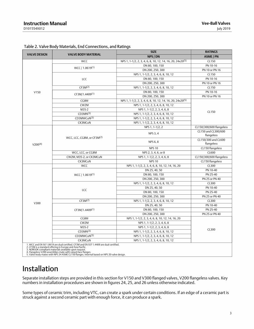
Table 2. Valve Body Materials, End Connections, and Ratings
VALVE DESIGN VALVE BODY MATERIALSIZE RATINGS
NPS / DN ASME / PN
V150
WCC NPS 1, 1-1/2, 2, 3, 4, 6, 8, 10, 12, 14, 16, 20, 24x20(5) CL150
WCC / 1.0619(1)DN 80, 100, 150 PN 10-16
DN 200, 250, 300 PN 10 or PN 16
LCC
NPS 1, 1-1/2, 2, 3, 4, 6, 8, 10, 12 CL150
DN 80, 100, 150 PN 10-16
DN 200, 250, 300 PN 10 or PN 16
CF3M(2) NPS 1, 1-1/2, 2, 3, 4, 6, 8, 10, 12 CL150
CF3M/1.4409(1)DN 80, 100, 150 PN 10-16
DN 200, 250, 300 PN 10 or PN 16
CG8M NPS 1, 1-1/2, 2, 3, 4, 6, 8, 10, 12, 14, 16, 20, 24x20(5)
CL150
CW2M NPS 1, 1-1/2, 2, 3, 4, 6, 8, 10, 12
M35-2 NPS 1, 1-1/2, 2, 3, 4, 6, 8
CD3MN(3) NPS 1, 1-1/2, 2, 3, 4, 6, 8, 10, 12
CD3MWCuN(3) NPS 1, 1-1/2, 2, 3, 4, 6, 8, 10, 12
CK3MCuN NPS 1, 1-1/2, 2, 3, 4, 6, 8, 10, 12
V200(4)
WCC, LCC, CG8M, or CF3M(2)
NPS 1, 1-1/2, 2 CL150/300/600 flangeless
NPS 3, 4CL150 and CL300/600
flangeless
NPS 6, 8CL150/300 and CL600
flangeless
NPS 10 CL150 flangeless
WCC, LCC, or CG8M NPS 2, 3, 4, 6, or 8 CL600
CW2M, M35-2, or CK3MCuN NPS 1, 1-1/2, 2, 3, 4, 6, 8 CL150/300/600 flangeless
CK3MCuN NPS 10 CL150 flangeless
V300
WCC NPS 1, 1-1/2, 2, 3, 4, 6, 8, 10, 12, 14, 16, 20 CL300
WCC / 1.0619(1)
DN 25, 40, 50 PN 10-40
DN 80, 100, 150 PN 25-40
DN 200, 250, 300 PN 25 or PN 40
LCC
NPS 1, 1-1/2, 2, 3, 4, 6, 8, 10, 12 CL300
DN 25, 40, 50 PN 10-40
DN 80, 100, 150 PN 25-40
DN 200, 250, 300 PN 25 or PN 40
CF3M(2) NPS 1, 1-1/2, 2, 3, 4, 6, 8, 10, 12 CL300
CF3M/1.4409(1)
DN 25, 40, 50 PN 10-40
DN 80, 100, 150 PN 25-40
DN 200, 250, 300 PN 25 or PN 40
CG8M NPS 1, 1-1/2, 2, 3, 4, 6, 8, 10, 12, 14, 16, 20
CL300
CW2M NPS 1, 1-1/2, 2, 3, 4, 6, 8
M35-2 NPS 1, 1-1/2, 2, 3, 4, 6, 8
CD3MN(3) NPS 1, 1-1/2, 2, 3, 4, 6, 8, 10, 12
CD3MWCuN(3) NPS 1, 1-1/2, 2, 3, 4, 6, 8, 10, 12
CK3MCuN NPS 1, 1-1/2, 2, 3, 4, 6, 8, 10, 12
1. WCC and EN Stl 1.0619 are dual certified. CF3M and EN SST 1.4409 are dual certified.2. CF3M is a standard offering in Europe and Asia Pacific.3. NORSOK compliant materials available upon request.4. Flangeless V200 assemblies mate with raised-face flanges.5. Valve body mates with NPS 24 ASME CL150 flanges. Internal based on NPS 20 valve design.
InstallationSeparate installation steps are provided in this section for V150 and V300 flanged valves, V200 flangeless valves. Keynumbers in installation procedures are shown in figures 24, 25, and 26 unless otherwise indicated.
Some types of ceramic trim, including VTC, can create a spark under certain conditions. If an edge of a ceramic part isstruck against a second ceramic part with enough force, it can produce a spark.
Instruction ManualD101554X012
Vee-Ball ValvesJuly 2019
4
WARNING
Avoid personal injury and property damage from ignition of process fluid caused by sparks from ceramic trim. Do not useceramic trim where the process fluid is unstable or if it is an explosive mixture (such as ether and air).
WARNING
Always wear protective gloves, clothing, and eyewear when performing any installation operations to avoid personalinjury.
Personal injury or equipment damage caused by sudden release of pressure may result if the valve assembly is installedwhere service conditions could exceed either the valve body rating or the mating pipe flange joint rating. To avoid suchinjury or damage, provide a relief valve for overpressure protection as required by government or accepted industry codesand good engineering practices.
Check with your process or safety engineer for any additional measures that must be taken to protect against processmedia.
If installing into an existing application, also refer to the WARNING at the beginning of the Maintenance section in thisinstruction manual.
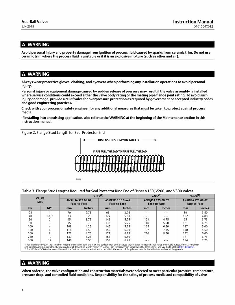
Figure 2. Flange Stud Length for Seal Protector End
DIMENSION SHOWN IN TABLE 3
1A4520
FIRST FULL THREAD TO FIRST FULL THREAD
Table 3. Flange Stud Lengths Required for Seal Protector Ring End of Fisher V150, V200, and V300 Valves
VALVESIZE
V150(2) V200(1) V300(2)
ANSI/ISA S75.08.02Face‐to‐Face
ASME B16.10 ShortFace‐to‐Face
ANSI/ISA S75.08.02Face‐to‐Face
ANSI/ISA S75.08.02Face‐to‐Face
DN NPS mm Inches mm Inches mm Inches mm Inches
25405080
100150200250300
11-1/2
23468
1012
70839595
108114121133140
2.753.253.753.754.254.504.755.255.50
95127146133146152171165159
3.755.005.755.255.756.006.756.506.25
- - -- - -121140165197216- - -- - -
- - -- - -
4.755.506.507.758.50- - -- - -
8910295
121127140152171184
3.504.003.754.755.005.506.006.757.25
1. For the flanged V200, the same bolt lengths are used for both the inlet and outlet flange ends because the studs for threaded flange holes are double nutted. If the Cavitrol Hexanti-cavitation trim is installed, the required outlet flange bolt length will be ½” longer than the Dimension specified in the table above. See Vee-Ball bulletin (D101363X012).2. For V150 and V300 valve assemblies with the Cavitrol Hex anti-cavitation trim installed, the same bolt lengths are used for both the inlet and outlet flange ends.
WARNING
When ordered, the valve configuration and construction materials were selected to meet particular pressure, temperature,pressure drop, and controlled fluid conditions. Responsibility for the safety of process media and compatibility of valve

Instruction ManualD101554X012
Vee-Ball ValvesJuly 2019
5
materials with process media rests solely with the purchaser and end‐user. To avoid possible personal injury and becausesome valve/trim material combinations are limited in their pressure drop and temperature ranges, do not apply any otherconditions to the valve without first contacting your Emerson sales office.
WARNING
The valve drive shaft is not necessarily grounded to the pipeline when installed. Personal injury or property damage couldresult from an explosion caused by a discharge of static electricity from valve components if the process fluid or theatmosphere around the valve is flammable. If the atmosphere around the valve or the process fluid is flammable,electrically bond the drive shaft to the valve.
Note
Standard PTFE packing is composed of a partially conductive carbon‐filled PTFE female adaptor with PTFE V‐ring packing. Standardgraphite packing is composed of all conductive graphite ribbon packing. Alternate shaft‐to‐valve body bonding is available forhazardous service areas where the standard packing is not sufficient to bond the shaft to the valve (see the following step).
Attach the optional bonding strap assembly (key 131, figure 3) to the valve drive shaft (key 6) with the clamp (key 130,figure 3) and connect the other end of the bonding strap assembly to the valve body with the cap screw (key 23).
1. If the valve is to be stored before installation, protect the flange mating surfaces and keep the valve body cavity dryand free of foreign material.
2. Install a three‐valve bypass around the control valve assembly if continuous operation will be necessary duringinspection and maintenance of the valve.
3. The valve is normally shipped as part of a control valve assembly, with an actuator mounted on the valve. If thevalve and actuator have been purchased separately or if the actuator has been removed, mount the actuatoraccording to the Actuator Mounting section and the appropriate actuator instruction manual.
4. Standard flow direction is with the seal protector ring (key 3) facing upstream.
5. Install the valve in a horizontal or vertical pipeline with the drive shaft in a horizontal position.
CAUTION
Do not allow the valve to be installed in the pipeline with the drive shaft in the vertical position because of excessive wearto valve component parts.
6. The actuator can be right‐ or left‐hand mounted with the shaft in a horizontal orientation as shown in figure 1. Ifnecessary, refer to the appropriate actuator instruction manual for actuator installation and adjustmentprocedures.
CAUTION
Ensure the valve and adjacent pipelines are free of foreign material that could damage the valve seating surfaces.
7. Be certain the valve and adjacent pipelines are free of any foreign material that could damage the valve sealingsurfaces.
8. Be sure the pipeline flanges are in line with each other.

Instruction ManualD101554X012
Vee-Ball ValvesJuly 2019
6
Installing V150, V300, and Flanged V200 Valves1. Install the V150 and V300 valve using studs (keys 32 and 33, not shown) and nuts to connect the valve flanges to
the pipeline flanges. The seal protector ring (key 3) end of the valve requires longer line flange studs (key 32) thanstandard. Do not use standard‐length line flange studs for the seal protector ring end of the valve. The sealprotector ring end of the valve for the DN25/NPS 1 constructions will have threaded flange holes due to insufficientnut clearance.
Figure 3. Optional Shaft‐to‐Body Bonding Strap Assembly
VALVEBODY
ACTUATORA
AVIEW A‐A37A6528‐AA3143‐2
2. See table 3 and figure 2 for length of studs for the seal protector ring end of V150 and V300 valves. Lubricate thestuds with anti‐seize lubricant.
3. Insert flat‐sheet line flange gaskets (or spiral‐wound gaskets with compression‐controlling center rings) that arecompatible with the flowing media.
4. Connect pressure lines to the actuator as indicated in the actuator instruction manual. When an auxiliary manualactuator is used with a power actuator, install a bypass valve on the power actuator (if one is not supplied) for useduring manual operation.
WARNING
Personal injury could result from packing leakage. Valve packing was tightened before shipment; however the packingmight require some readjustment to meet specific service conditions. Check with your process or safety engineer for anyadditional measures that must be taken to protect against process media.
If the valve has ENVIRO‐SEAL live‐loaded packing installed, this initial re‐adjustment will probably not be required. SeeENVIRO‐SEAL Packing System for Rotary Valves instruction manual (D101643X012) for packing instructions.
Instruction ManualD101554X012
Vee-Ball ValvesJuly 2019
7
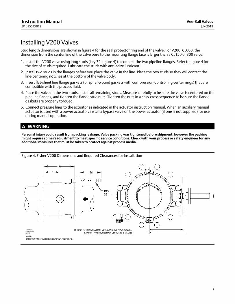
Installing V200 ValvesStud length dimensions are shown in figure 4 for the seal protector ring end of the valve. For V200, CL600, thedimension from the center line of the valve bore to the mounting flange face is larger than a CL150 or 300 valve.
1. Install the V200 valve using long studs (key 32, figure 4) to connect the two pipeline flanges. Refer to figure 4 forthe size of studs required. Lubricate the studs with anti‐seize lubricant.
2. Install two studs in the flanges before you place the valve in the line. Place the two studs so they will contact theline‐centering notches at the bottom of the valve body.
3. Insert flat‐sheet line flange gaskets (or spiral‐wound gaskets with compression‐controlling center rings) that arecompatible with the process fluid.
4. Place the valve on the two studs. Install all remaining studs. Measure carefully to be sure the valve is centered on thepipeline flanges, and tighten the flange stud nuts. Tighten the nuts in a criss‐cross sequence to be sure the flangegaskets are properly torqued.
5. Connect pressure lines to the actuator as indicated in the actuator instruction manual. When an auxiliary manualactuator is used with a power actuator, install a bypass valve on the power actuator (if one is not supplied) for useduring manual operation.
WARNING
Personal injury could result from packing leakage. Valve packing was tightened before shipment; however the packingmight require some readjustment to meet specific service conditions. Check with your process or safety engineer for anyadditional measures that must be taken to protect against process media.
Figure 4. Fisher V200 Dimensions and Required Clearances for Installation
179 mm (7.06 INCHES) FOR CL600 NPS 6 VALVES164 mm (6.44 INCHES) FOR CL150 AND 300 NPS 6 VALVES
95BA02100BA6956
A
B M
KEY32
12B3060‐L
NOTE:REFER TO TABLE WITH DIMENSIONS ON PAGE 8

Instruction ManualD101554X012
Vee-Ball ValvesJuly 2019
8
V200VALVESIZE,NPS
DIMENSION
A
B
M
StandardANSI/ISA
S75.08.02(1)
CL150ASME B16.10(2)
Short (Optional)
StandardCL150 ANSI/ISA
S75.08.02(1)
CL150ASME B16.10(2)
Short (Optional)CL300 CL600
mm
11-1/2
2
102114124
127165178
586457
176189211
202240268
202224237
202224237
346
165194229
203229267
8792
119
254286343
286321381
279305362
286343423
810
243297
292330
119151
343419
394451
387‐ ‐ ‐
426‐ ‐ ‐
Inches
11-1/2
2
4.004.504.88
5.006.507.00
2.292.502.25
6.947.448.31
7.949.44
10.56
7.948.819.31
7.948.819.31
346
6.507.629.00
8.009.00
10.50
3.443.624.69
10.0011.2513.50
11.2512.6215.00
11.0012.0014.25
11.2513.5016.25
810
9.5611.69
11.5013.00
4.695.94
13.5016.50
15.5017.75
15.25‐ ‐ ‐
16.75‐ ‐ ‐
1. IEC 534‐3‐2 face‐to‐face dimensions are equivalent to ANSI/ISA S75.08.02 face‐to‐face dimensions.2. 150 pound class only.
MaintenanceValve parts are subject to normal wear and must be inspected and replaced as necessary. The frequency of inspectionand replacement depends upon the severity of service conditions.
Key numbers in this procedure are shown in figures 24, 25, and 26, unless otherwise noted.
WARNING
The Vee‐ball closes with a shearing, cutting motion, which could result in personal injury. To avoid injury, keep hands,tools, and other objects away from the Vee‐ball while stroking the valve.
Avoid personal injury from sudden release of process pressure. Before performing any maintenance operations:
� Do not remove the actuator from the valve while the valve is still pressurized.
� Disconnect any operating lines providing air pressure, electric power, or a control signal to the actuator. Be sure theactuator cannot suddenly open or close the valve.
� Use bypass valves or completely shut off the process to isolate the valve from process pressure. Relieve process pressurefrom both sides of the valve. Drain the process media from both sides of the valve.
� Vent the power actuator loading pressure and relieve any actuator spring precompression.
� Use lock‐out procedures to be sure that the above measures stay in effect while you work on the equipment.
� Always wear protective gloves, clothing, and eyewear when performing any maintenance operations.
� The valve packing area may contain process fluids that are pressurized, even when the valve has been removed from thepipeline. Process fluids may spray out under pressure when removing the packing hardware or packing rings.
� Check with your process or safety engineer for any additional measures that must be taken to protect against processmedia.
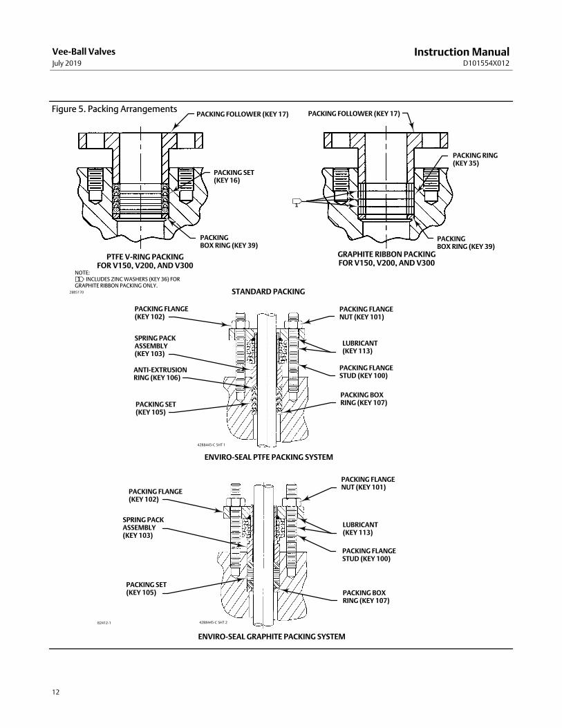
Packing MaintenanceKey numbers in this procedure are shown in figures 24, 25, and 26, unless otherwise noted. A detailed view of thepacking is also shown in figure 5.

Instruction ManualD101554X012
Vee-Ball ValvesJuly 2019
9
If the valve is equipped with the ENVIRO‐SEAL Packing System, refer to:
� the separate ENVIRO‐SEAL Packing System for Rotary Valves instruction manual (D101643X012) for maintenanceinstructions, and
� the Parts List section of this manual for retrofit kits, parts kits, and individual parts.
If the packing is relatively new and tight on the drive shaft (key 6), and if tightening the packing follower nuts does notstop leakage, it is possible that the drive shaft is worn or nicked so that a seal cannot be made. If the leakage comesfrom the outside diameter of the packing, it is possible that the leakage is caused by nicks or scratches on the packingbox wall. Inspect the drive shaft and packing box wall for nicks or scratches while performing the following procedure.
Replacing Packing
When using this procedure, it is recommended that the actuator not be removed from the valve while the valve is stillin the pipeline or between flanges. Valve/actuator adjustments must be made with the valve out of the pipeline. Referto the Determining Closed Position portion of the Actuator Mounting section.
Disassembly
WARNING
Observe the steps in the WARNING at the beginning of the Maintenance section.
1. Isolate the control valve from the line pressure, release pressure from both sides of the valve body, and drain theprocess media from both sides of the valve. If using a power actuator, shut off all pressure lines to the poweractuator, release pressure from the actuator, and disconnect the pressure lines from the actuator. Use lock‐outprocedures to be sure that the above measures stay in effect while you are working on the equipment.
2. Remove line bolting, remove the control valve from the pipeline, and place the valve/actuator assembly on a flatsurface with the seal protector ring facing up.
3. Remove the actuator cover. Take note of the orientation of the actuator with respect to the valve body and thelever orientation with respect to the valve drive shaft (see figure 6).
WARNING
When the actuator is removed from the valve, the ball/shaft assembly may suddenly rotate, with a shearing, cuttingmotion, which could result in personal injury. To avoid injury, carefully rotate the ball to a stable position after the actuatoris removed.
CAUTION
When removing the actuator from the valve, do not use a hammer or similar tool to drive the lever or actuator off the valveshaft. Driving the lever or actuator off the valve shaft could damage the ball, seal, and valve. If necessary, use a puller toremove the lever or actuator from the valve shaft. It is okay to tap the puller screw lightly to loosen lever or actuator, buthitting the screw with excessive force could damage the ball, seal, and valve.
4. Remove the clamped lever (do not loosen the actuator turnbuckle adjustment), remove the actuator mountingscrews and nuts (keys 23 and 24), and remove the actuator. (If necessary, refer to the actuator instruction manualfor assistance.)

Instruction ManualD101554X012
Vee-Ball ValvesJuly 2019
10
5. If applicable, remove the bonding strap assembly before attempting to remove the packing (see figure 3).
6. Remove the packing follower nuts and packing follower (keys 17 and 20). For alloy packing constructions, thepacking follower (key 17) and a separate packing flange (key 40) must be removed if present.
If the valve is equipped with the ENVIRO‐SEAL packing system, refer to the ENVIRO‐SEAL Packing System for RotaryValves instruction manual (D101643X012) for disassembly.
WARNING
Personal injury could result from packing leakage. Do not scratch the drive shaft or packing box wall while removingpacking parts in the following procedure.
7. Remove the packing parts (see figure 5, keys 16, 17, 35, and 39 depending on construction) using a formed wirehook with a sharp end. Pierce the rings with the sharp end of the hook in order to remove them. Do not scratch thedrive shaft or packing box wall; scratching these surfaces could cause leakage. Clean all accessible metal parts andsurfaces to remove particles that would prevent the packing from sealing.
Assembly
If the valve is equipped with the ENVIRO‐SEAL packing system, refer to the ENVIRO‐SEAL Packing System for RotaryValves instruction manual (D101643X012) for assembly.
Series B only
1. For NPS 8, 10, and 12 valves, install the packing spacer (key 34) if it has been removed.
2. To help ensure correct centering of the Vee‐ball (key 2) on the seal (key 11), make sure the ball is closed while youinstall or tighten new packing. Insert a screwdriver, pry bar, or similar tool between the lower ear of the ball and thevalve body. Use the pry to move the ball tightly against the bearing on the actuator side of the valve (see figure 6).Keep the ball in that position until you have completed packing installation and adjustment.
3. Install the new packing parts using the parts sequence shown in figure 5. Install the packing follower (key 17). Alloyconstructions have a packing follower (key 17) and a separate packing flange (key 40) that must be replaced.
4. Secure the packing follower with the packing follower nuts (key 20). Tighten the nuts far enough to stop leakageunder operating conditions.
Handle the seal protector ring, seal, and other parts carefully to prevent damage. A new gasket (key 15) is requiredwhenever the seal protector ring (key 3) (figure 11) is removed.
Flow ring construction does not use a seal, shims, or spring seal. Use this procedure to remove the seal protector ringfrom flow ring constructions, but disregard any instructions calling for the seal, shims, or spring seal.
Note
If the valve is equipped with a bonding strap assembly (figure 3), re‐install the assembly.
5. Reconnect the actuator and lever in accordance with the orientations that were noted in step 3 of the disassemblyprocedures. If necessary, use figure 23 to identify the correct index marks.
6. Refer to the appropriate actuator instruction manual to complete actuator assembly and adjustment.
7. When the control valve is in operation, check the packing follower for leakage and retighten the packing followernuts (key 20) as necessary.

Instruction ManualD101554X012
Vee-Ball ValvesJuly 2019
11
Replacing the Ball Seal
Disassembly
Perform this procedure if the control valve is not shutting off properly or if seal inspection is necessary. If you find uponinspection that the ball, shaft, or bearings need to be replaced, use this procedure to remove the ball seal. Then,proceed to the Bearing and Ball Maintenance procedures. Then, return to this procedure and begin with the assemblyof the ball seal steps.
While the actuator/valve assembly must be removed from the pipeline, the actuator may remain mounted on thevalve as you replace the ball seal.
Key numbers are shown in figures 24, 25, and 26, unless otherwise indicated. Ball Seal assembly details (with keynumbers) are also shown in figures 8, 9, and 10.
Instruction ManualD101554X012
Vee-Ball ValvesJuly 2019
12
Figure 5. Packing ArrangementsPACKING FOLLOWER (KEY 17)
PACKING SET(KEY 16)
PACKING RING(KEY 35)
PACKINGBOX RING (KEY 39)
PACKING FLANGE(KEY 102)
SPRING PACKASSEMBLY(KEY 103)
ANTI‐EXTRUSIONRING (KEY 106)
PACKING SET(KEY 105)
PACKING FLANGENUT (KEY 101)
LUBRICANT(KEY 113)
PACKING FLANGESTUD (KEY 100)
PACKING BOXRING (KEY 107)
PACKING FLANGE(KEY 102)
SPRING PACKASSEMBLY(KEY 103)
PACKING SET(KEY 105)
PACKING FLANGENUT (KEY 101)
LUBRICANT(KEY 113)
PACKING FLANGESTUD (KEY 100)
PACKING BOXRING (KEY 107)
NOTE:��INCLUDES ZINC WASHERS (KEY 36) FOR GRAPHITE RIBBON PACKING ONLY.
GRAPHITE RIBBON PACKINGFOR V150, V200, AND V300
PTFE V‐RING PACKINGFOR V150, V200, AND V300
STANDARD PACKING
ENVIRO‐SEAL PTFE PACKING SYSTEM
ENVIRO‐SEAL GRAPHITE PACKING SYSTEM
1
28B5170
42B8445‐C SHT 1
42B8445‐C SHT 2B2412‐1
PACKING FOLLOWER (KEY 17)
PACKINGBOX RING (KEY 39)
1

Instruction ManualD101554X012
Vee-Ball ValvesJuly 2019
13
Figure 6. Typical Vee‐Ball Valve Showing Pry Bar
BALL
ACTUATOR SIDEOF VALVE
58B2296‐BE0739
THRUST AND BEARING SURFACE
PRY IN THIS DIRECTION
WARNING
Perform the steps in the WARNING at the beginning of the Maintenance section of this manual.
1. Remove line bolting, remove the control valve from the pipeline, and place the valve on a flat surface with the sealprotector ring facing up. Carefully rotate the ball to the open position.
2. Remove protector ring screws and washers (keys 21 and 22). Carefully remove the seal protector ring and gasket(keys 3 and 15). (For flow ring constructions, go to step 4.)
a. For a Fisher TCM seal, remove the seal (key 11) from the valve body. For NPS 1, 1-1/2, and 2 valves, also removethe backup ring (key 14, figure 8) from the valve body.
b. For a flat metal seal, remove the spring seal, seal, and shims (keys 13, 11, and 12). (Note: It may be necessary tore‐use some of the original shims when reassembling the flat metal seal.)
c. For an HD ball seal or a high temperature HD ball seal, once the protector ring has been removed from the valve,push the metal seal (key 11) out of the seal protector ring (key 3). Remove the wave spring (key 13), and on theHD metal seal, the radial seal (key 37).
Note
The high temperature HD ball seal also has a piston ring (key 133) that will need to be removed. It will be in two pieces for the NPS1, 1-1/2 and 2 valves, and one piece with a break in it for the NPS 3 through 12 valves.
CAUTION
Exercise care to avoid damaging components in the following procedure.
Instruction ManualD101554X012
Vee-Ball ValvesJuly 2019
14
� It might be necessary to remove the HD seal by carefully tapping it with a soft punch and hammer. Takecare not to damage the seal protector ring.
� NPS 3 through 12 valves, if the seal is difficult to push out, it is recommended that a seal removal plate beused to press the HD seal out of the seal protector ring. Refer to figure 12 for dimensions of the sealremoval plate.
� NPS 10 and 12 valves with an attenuator only: Remove the retaining ring (key 41) in the seal protector ring.This retaining ring is an octagonal‐shaped support wire. To remove the retaining ring, find one of the freeends of the ring. Use a screwdriver or similar tool to pry inward and upward until the ring is removed.
3. Inspect the gasket and sealing surfaces on the valve body (key 1 or 1A), the seal protector ring (key 3), Vee‐Ball (key2), and the retaining ring (key 41 for NPS 10 and 12 valves with an attenuator only). Be sure the sealing surfaces arenot damaged.
4. If replacement of the ball, shafts (keys 6 or 9), or bearings (key 10) is needed, proceed to the Bearing and BallMaintenance procedure. If only the seal is to be replaced, proceed to the Assembly steps below.
Assembly
Refer to figures 8, 9, and 10 for key number locations during seal installation. Valve key number locations are shown infigures 24, 25, and 26.
1. Thoroughly clean all parts that are to be re‐used and obtain replacement parts. Be sure that all sealing surfaces arein good condition without scratches or wear. If the valve has been installed between line flanges and the flangestuds and nuts have been tightened, always replace the gasket (key 15) with a new gasket.
2. To help ensure correct side‐to‐side centering of the ball (key 2) on the seal (key 11), make sure the ball is closedwhile you install the seal or flow ring and seal protector ring. Insert a screwdriver, pry bar, or similar tool betweenthe lower ear of the ball and the valve body (see figure 6).
3. Use the pry to move the ball tightly against the bearing on the actuator side of the valve. Be careful, excessive forcemay damage the ball. Keep the ball in that position until you have completed seal or flow ring installation. Checkthe ball's position periodically, and re‐center if necessary, during lever assembly and packing adjustments.
WARNING
The Vee‐Ball closes with a shearing, cutting motion, which could result in personal injury. To avoid injury or propertydamage, keep hands, tools, and other objects away from the Vee‐Ball while stroking the valve.
4. Install the seal.
CAUTION
Due to the Vee‐ball shape, take care to never completely rotate either the front skirted edge or the circular back edge of theball out of the ball seal as the seal could be damaged.

Instruction ManualD101554X012
Vee-Ball ValvesJuly 2019
15
Figure 7. NPS 1 and 1-1/2 Seal Protector Ring Measurements
CL150 ASME B16.10 (SHORT) FACE‐TO‐FACE VALVE
D
A6960
ANSI/ISA S75.08.02 FACE‐TO‐FACE VALVE
D
A6959
ValveSize, DN
ValveSize,NPS
Construction(1)TCMSeal“D”
HD Seal“D”
FlowRing“D”
mm
25 1New 37.6 44.7 39.6
Old 25.1 33.0 26.9
40 1-1/2New 39.1 44.5 40.9
Old 27.4 32.8 29.2
Inches
25 1New 1.48 1.76 1.56
Old 0.99 1.30 1.06
40 1-1/2New 1.54 1.75 1.61
Old 1.08 1.29 1.15
1. See the Note on page 14 of this Instruction Manual.
Valve Size,NPS
Construction(1) TCM Seal“D”
HD Seal“D”
Flow Ring“D”
mm
1New 63.0 70.1 65.0
Old 50.5 58.4 52.3
1-1/2New 89.9 95.3 91.7
Old 78.2 83.6 80.0
Inches
1New 2.48 2.76 2.56
Old 1.99 2.30 2.06
1-1/2New 3.54 3.75 3.61
Old 3.08 3.29 3.15
1. See the Note on page 14 of this Instruction Manual.
Figure 8. Ball Seal Assembly for NPS 1, 1-1/2, and 2 Valves
SEAL PROTECTOR RING (KEY 3)
GASKET(KEY 15)
BALL SEAL(KEY 11)
VALVE BODY(KEY 1)
BACKUP RING(KEY 14)
BALL (KEY 48)
SEAL PROTECTORRING (KEY 3)
GASKET(KEY 15)
RADIAL SEAL(KEY 37)
HD METAL BALLSEAL (KEY 11)
APPLYDRY FILMLUBRICANT
WAVE SPRING(KEY 13)
BALL (KEY 48)
VALVE BODY(KEY 1)
Fisher TCM Plus BALL SEAL HD BALL SEALA6032‐2

Instruction ManualD101554X012
Vee-Ball ValvesJuly 2019
16
Figure 9. Ball Seal Assembly for NPS 3 through 12 Valves
GASKET(KEY 15)
SEAL PROTECTORRING (KEY 3)
VALVE BODY(KEY 1A)
SEAL(KEY 11)
BALL(KEY 2)
GASKET(KEY 15)
SEAL PROTECTORRING (KEY 3)
SHIMS(KEY 12)
SPRING SEAL(KEY 13)
FLAT METALSEAL (KEY 11)
APPLY DRY FILMLUBRICANT
WAVE SPRING(KEY 13)
RADIAL SEAL(KEY 37)
HD METAL BALLSEAL (KEY 11)
RETAINING RINGWITH ATTENUATOR ONLY (KEY 41)
GASKET(KEY 15)
GASKET(KEY 15)
SEAL PROTECTORRING (KEY 3)
SEAL PROTECTORRING (KEY 3)
APPLY DRYFILMLUBRICANT
WAVE SPRING(KEY 13)
RADIAL SEAL(KEY 37)
HD METALBALLSEAL (KEY 11)
NPS 3 THROUGH 12FISHER TCM PLUS SEAL
NPS 3 THROUGH 12FLAT METAL BALL SEAL
NPS 3 THROUGH 8HD BALL SEAL NPS 10 AND 12
HD BALL SEAL
41B0742‐EB2338‐3
Figure 10. High Temperature HD Ball Seal Details
SEAL PROTECTOR RING
SEAL PROTECTOR RING
RETAINING RING
PISTON RING
PISTON RING
HD METAL SEAL
HD METAL SEAL
WAVE SPRING
WAVE SPRING
USE ONLY WHENATTENUATOR IS USED
NPS 3 THROUGH 8AND 14 THROUGH 20HD METAL BALL SEAL NPS 10 AND 12
HD METAL BALL SEAL
NPS 1, 1-1/2 AND 2HD METAL BALL SEAL
28B9882‐EE0261

Instruction ManualD101554X012
Vee-Ball ValvesJuly 2019
17
Figure 11. Seal Protector Ring
SEAL PROTECTORRING (KEY 3)
Figure 12. HD Seal Removal Plate Dimensions
A5544
A
6.4 mm(0.250 INCHES)MINIMUM
VALVE SIZE DIMENSION A
DN NPS Minimum‐Maximum, mm Minimum‐Maximum, Inches
80100150200250300
3468
1012
75.9‐76.295.0‐95.3
126.7‐127.0158.5‐158.8212.5‐212.7263.3‐263.5
2.990‐3.0003.740‐3.7504.990‐5.0006.240‐6.2508.365‐8.375
10.365‐10.375
Installing Fisher TCM Plus or Extra ball seals:
a. NPS 1, 1-1/2, and 2 valves: Install the backup ring (key 14). Install the Fisher TCM seal (key 11) into the valvebody. Refer to figure 7.
� Install the gasket (key 15) on the valve body.
� Install the seal protector ring (key 3) into the valve body. Now go to step 5 in this procedure.
b. NPS 3 through 12 valves: Install the Fisher TCM seal (key 11) into the valve body.
� Install the gasket (key 15) on the valve body.
� Install the seal protector ring (key 3) into the valve body. Now go to step 5 in this procedure.

Instruction ManualD101554X012
Vee-Ball ValvesJuly 2019
18
Installing flat metal seals:
a. Install 12 shims in the valve and install the flat metal seal on top of the shims.
b. Install the spring seal (key 13) on the flat metal seal (key 11) with the convex side of the spring seal facing theball.
c. Install the seal protector ring, and install the protector ring screws and washers (keys 21 and 22). Tighten thescrews.
d. Add or remove shims under the ball seal as necessary to obtain zero ball seal deflection as accurately as possible.
Note
Zero ball seal deflection for a flat metal seal is the point at which the addition of one 0.13 mm (0.005 inch) thick shim causescontact between the ball and ball seal to be broken. Hold the parts tightly together when determining zero deflection, or improperzero deflection might result.
e. After zero deflection is reached, remove the seal protector ring, spring seal, seal and 4 shims. Final assembly ofthe control valve should not exceed a maximum of 9 shims for zero deflection. If more than 9 shims are required,contact your Emerson sales office.
f. Install the gasket (key 15) on the valve body.
g. Install the seal protector ring (key 3) into the valve body. Now go to step 5 in this procedure.
Installing HD ball seals:
Note
The older and newer designs of the NPS 1 and 1-1/2 seal protector ring are functionally the same, but are different lengths and notinterchangeable. All NPS 1 and 1-1/2 sizes of V150 and V300 valves are the newer design. The change in seal protector ring lengthoccurred in the 1992/1993 timeframe and affects NPS 1 and 1-1/2 V200 valves only. To determine whether you have the older ornewer design, measure the length of the seal protector ring (key 3, figure 26) from its pipeline flange mating surface to itsopposite end. Compare your measurement to those listed in figure 7.
a. For NPS 1 and 1-1/2 valves: The older and newer designs of the NPS 1 and 1-1/2 seal protector rings arefunctionally the same, but are different lengths and not interchangeable. Refer to figure 7 for protector ringdimensions.
� Install the wave spring (key 13) onto the ball seal.
� Lubricate and install the radial seal (key 37) onto the ball seal (key 11). Make sure the open side of the radialseal faces away from the ball.
� Push the ball seal assembly into the seal protector ring (key 3).
� Go to step 5 in this procedure.

Instruction ManualD101554X012
Vee-Ball ValvesJuly 2019
19
b. For all NPS 3 through 8 valves and NPS 10 and 12 valves without attenuator:
� Lubricate and install the radial seal (key 37) into the appropriate groove in the seal protector ring makingsure the open side of the radial seal faces away from the ball.
� Install the wave spring (key 13) into the seal protector ring (key 3).
� Install the HD seal (key 11) into the seal protector ring (key 3), past the radial seal. While pushing it past theradial seal, make sure the HD seal is level. Go to step 5 in this procedure.
c. For NPS 10 and 12 valves with attenuator:
� Lubricate the radial seal with lithium grease and install the radial seal (key 37) into the appropriate groovein the seal protector ring making sure the open side of the radial seal faces away from the ball.
� Install the wave spring (key 13) into the seal protector ring (key 3).
� To install the retaining ring (key 41), find one of the free ends of the ring. Insert the free end into the groovein the seal protector ring. Work around the ring, pressing it into the groove until the ring is completely in itsgroove.
� Install the HD seal (key 11) into the seal protector ring (key 3), past the radial seal. While pushing it past theradial seal, make sure the HD seal is level.
� The HD seal uses a retaining ring (key 41) for NPS 10 and 12 valves only. This retaining ring is anoctagonal‐shaped support wire. Go to step 5 in this procedure.
Installing high temperature HD ball seals:
a. For NPS 1, 1-1/2 and 2 valves: The older and newer designs of the NPS 1 and 1-1/2 seal protector rings arefunctionally the same, but are different lengths and not interchangeable. All part numbers in this manual are forthe newer design. Refer to figure 7 for ring dimensions.
� Place the wave spring (key 13) on top of the HD seal (key 11).
� Break the piston ring (key 133) into two approximately equal pieces either by placing the ring over a pencilor similar object and applying pressure down‐wards on the ring until the ring snaps. Be sure to match thebroken ends together as you install it on the HD seal (key 11).
� Lay the HD seal (key 11) down on a flat surface and push the seal protector ring (key 3) into place. Makesure the seal is level. Go to step 5 in this procedure.
b. For NPS 3 through 8 valves:
� Place the piston ring (key 133) and retaining ring (key 132) into the appropriate groove in the seal protectorring (key 3). The piston ring has one break in it; do not break it further.
� Install the wave spring (key 13) into the seal protector ring (key 3).
� Lay the HD seal (key 11) down on a flat surface and push the seal protector ring (key 3) past the piston ring(key 133) and into place. Make sure the seal is level. Go to step 5 in this procedure.

Instruction ManualD101554X012
Vee-Ball ValvesJuly 2019
20
c. For NPS 10 and 12 valves:
� Place the piston ring (key 133) and retaining ring (key 132) into the appropriate groove in the seal protectorring (key 3). The piston ring has one break in it; do not break it further.
� Install the wave spring (key 13) into the seal protector ring (key 3).
� If the valve has an attenuator, install the retaining ring (key 41). The octagonal shaped support wire ring hastwo free ends. Place one of the free ends into the groove in the seal protector ring. Then starting at theinserted end, press the rest of the ring into the groove completely.
� Lay the HD seal (key 11) down on a flat surface and push the seal protector ring (key 3) past the piston ring(key 133) and into place. Make sure the seal is level. Go to step 5 in this procedure.
5. Install a replacement gasket (key 15) on the valve body (key 1 or 1A). Install the HD ball seal/seal protector ringassembly into the valve body (key 1 or 1A).
6. Install washers (or clips), and screws that clamp the seal protector ring to the valve body [keys 3, 21, and 22; theV200 valve uses clips (key 22) in place of washers].
7. If necessary, refer to the Packing Maintenance procedures to install the packing. Install the actuator using theActuator Mounting procedures or to the appropriate actuator instruction manual.
HD Ball Seal Lubrication
To assist with break‐in of the HD seals, it is recommended that the ball and seal be lubricated with dry film lubricant orequivalent moly disulfide.
Bearing and Ball Maintenance
WARNING
Before performing the steps in this section, observe the WARNING at the beginning of the Maintenance section on page 8.
DN 80 - 300 (NPS 3 through 12) Valves
Procedures for disassembly and assembly of the bearings and ball cannot be accomplished until the ball seal and valvepacking are removed from the valve.
Refer to the Replacing Packing procedures to remove the actuator, and to remove the packing flange and packingfollower from the valve. When the packing disassembly steps are complete, return to this section.
Refer to the Replacing the Ball Seal procedures to remove the ball seal from the valve.
Table 4. Continuous Threaded RodValve Size, DN Valve Size, NPS Threaded Rod Thread Size Thread Depth in Follower Shaft
80 3 0.25-20 0.5
100 4 0.25-20 0.5
150 6 0.25-20 0.5
200 8 0.3125-18 0.62
250 10 0.3125-18 0.62
300 12 0.3125-18 0.94

Instruction ManualD101554X012
Vee-Ball ValvesJuly 2019
21
Disassembly
WARNING
When the actuator is removed from the valve, the ball/shaft assembly may suddenly rotate, with a shearing, cuttingmotion, which could result in personal injury. To avoid injury, carefully rotate the ball to a stable position at the bottom ofthe valve body cavity. Make sure the ball will not rotate.
Key numbers in this procedure are shown in figures 24, 25, and 26, unless otherwise indicated.
1. A taper key (key 4, figures 14, 24, 25 and 32) is used to connect the ball and drive shaft in NPS 3 through 12 valves.
2. Carefully rotate the ball to the open position after the actuator is disconnected. Make sure the ball will not rotate(see warning above). Provide support for the ball during the following disassembly.
3. Working from the small end of the groove pin (key 7), use a pin punch to drive the groove pin out of the ball ear andfollower shaft.
For tack welded taper keys, driving the taper key out of the ball ear will shear the tack welding.
4. Locate the small end of the taper key (key 4, see figures 14, 24, 25 and 32). Using a pin punch on the smaller end ofthe taper key, drive it out of the ball (key 2) and drive shaft (key 6). Note: driving the taper key in the wrongdirection will tighten it.
5. Pull the drive shaft (key 6) out of the actuator side of the valve body.
CAUTION
Exercise care to avoid damaging components in the following procedure.
6. The ball will be free to move when both shafts are removed. Make sure the sealing surface of the ball is notdamaged while removing the follower shaft.
a. Unscrew the pipe plug (key 25) if one is installed. Use a punch to drive the follower shaft (key 9) into the center ofthe ball.
b. If a pipe plug is not installed, use a piece of continuous threaded rod as a removal rod when moving the followershaft (key 9) into the center of the ball. Refer to the table 4 for a description of the size threaded rod needed. Thelength of the rod should allow easy working room from the valve body.
7. Carefully remove the follower shaft and ball (key 2) from the valve body.
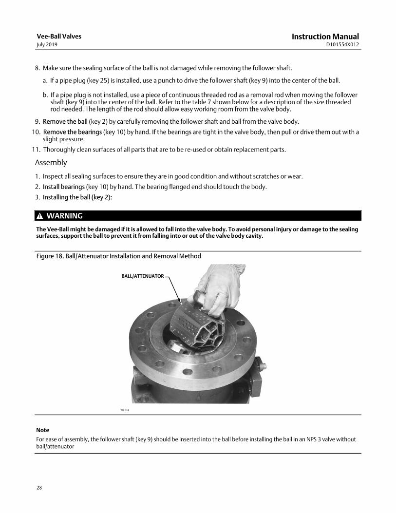
For NPS 4 valves with attenuator, remove the ball/attenuator through the inlet of the valve. Taking hold of the followershaft ear on the ball/attenuator, you must position the scalloped edge of the attenuator against the valve boreopening and then pivot, or roll, the ball/attenuator out of the valve body (see figure 18).
For NPS 6, 8, 10, and 12 valves with attenuator, remove the ball/attenuator through the outlet of the valve by carefullyturning and manipulating the ball. The NPS 6, 8, 10, or 12 ball/attenuator will not come straight out of the valve body.
8. Remove the bearings (key 10) by hand. If the bearings are tight in the valve body, then pull or drive them out with aslight pressure.
� To remove the follower shaft bearings, use a blind‐hole bearing puller. If you do not have such a tool, you canmachine the bearing out.
Instruction ManualD101554X012
Vee-Ball ValvesJuly 2019
22
9. Thoroughly clean surfaces of all parts that are to be re‐used or obtain replacement parts.
Assembly
1. Inspect all sealing surfaces to ensure they are in good condition and without scratches or wear.
2. Install the replacement bearings (key 10) by hand. The bearing flanged end should touch the valve body.
3. Installing the Vee‐Ball: Ensure the ball part number matches up with the appropriate seal type as shown in the key 2ball table in the parts list section of this instruction manual.
WARNING
The ball might be damaged if it is allowed to fall into the valve body. To avoid personal injury or damage to the sealingsurfaces, support the ball to prevent it from falling into or out of the valve body cavity.
Note
For ease of assembly, the follower shaft (key 9) should be inserted into the ball before installing the ball in the followingapplications:
� NPS 3 valve without ball/attenuator
� NPS 4 through 12 valves with ball/attenuator.
Carefully install the ball into the valve body cavity.
� For Vee‐Ball with attenuator (NPS 4 through 12 valves), carefully install the ball into the valve body cavity. For NPS 4valves, install the ball/attenuator through the inlet of the valve. For NPS 6, 8, 10, and 12 valves, install theball/attenuator through the outlet of the valve. Taking hold of the follower shaft ear on the ball/attenuator, youmust position the scalloped edge of the attenuator against the valve bore opening and then carefully pivot, or roll,the ball/attenuator into the valve body (see figure 18).
After you have installed the ball (key 2) into the valve body assembly, firmly support the ball while installing the shafts.
4. Installing the follower shaft (key 9):
� For NPS 3 valves: The follower shaft (key 9) should already have been inserted into the ball before the ball was putinto the valve body. Insert the follower shaft (key 9) into the valve body bearing (key 10).
� For NPS 4 and larger valves: Insert the follower shaft (key 9) through the ball, and into the valve body bearing (key10).
� For NPS 4 through 12 valves with ball/attenuator: The follower shaft (key 9) should already have been inserted intothe ball/attenuator before the ball was put into the valve body. Insert the follower shaft (key 9) into the valve bodybearing (key 10).
Then for all sizes, align the hole in the follower shaft with the holes in the ball. Insert the small end of the groove pin(key 7) into the hole in the ball and into the follower shaft. The pin will hold the parts in place while the drive shaft (key6) is being installed.

Instruction ManualD101554X012
Vee-Ball ValvesJuly 2019
23
Table 5. Taper Key Minimum Depth
Valve Size, DN Valve Size, NPSMinimum Depth To Drive Taper Key
After Initial Solid Contact, mm (Inches)
80, 100, 150200, 250, 300
3, 4, 68, 10, 12
4.8 (0.188)5.6 (0.219)
Table 6. Taper Key Maximum Depth
Valve Size, DN Valve Size, NPSMaximum Depth To Drive Taper Key
After Initial Solid Contact, mm (Inches)
80, 100150
200, 250300
3, 46
8, 1012
7.1 (0.281)7.9 (0.312)9.5 (0.375)
10.3 (0.406)
5. Installing the Drive Shaft:
CAUTION
The drive shaft must be used with the correct Vee‐Ball. Refer to the tag (see figure 13) attached to the Vee‐Ball and to thedrive shaft.
Failure to use the correct Vee‐Ball/shaft combination may result in the ball not being in the position indicated by the slashmark on the end of the shaft. If the ball is not properly aligned with the slash mark, the valve will not function correctly andseal damage may result.
Figure 13. Informational Tag
GE11636‐AFOR STANDARD RIGHT/LEFT HAND BALL GE11637‐A FOR OPTIONAL LEFT HAND BALL
CAUTION
Make sure the drive shaft is free of oil or grease, otherwise the taper pin or taper key will not seat properly. Failure toproperly set the taper pin or taper key could result in it coming loose while in service. Loosening of the taper key in servicecould result in improper valve function and equipment damage.
Instruction ManualD101554X012
Vee-Ball ValvesJuly 2019
24
a. Insert the drive shaft into the valve body bearing (key 10), and into the ball ear. Align the hole in the drive shaftwith the holes in the ball.
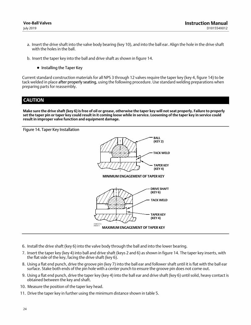
b. Insert the taper key into the ball and drive shaft as shown in figure 14.
� Installing the Taper Key
Current standard construction materials for all NPS 3 through 12 valves require the taper key (key 4, figure 14) to betack welded in place after properly seating, using the following procedure. Use standard welding preparations whenpreparing parts for reassembly.
CAUTION
Make sure the drive shaft (key 6) is free of oil or grease, otherwise the taper key will not seat properly. Failure to properlyset the taper pin or taper key could result in it coming loose while in service. Loosening of the taper key in service couldresult in improper valve function and equipment damage.
Figure 14. Taper Key Installation
MAXIMUM ENGAGEMENT OF TAPER KEY31B0727‐EA6035‐1
BALL(KEY 2)
TACK WELD
TAPER KEY(KEY 4)
DRIVE SHAFT(KEY 6)
TACK WELD
TAPER KEY(KEY 4)
MINIMUM ENGAGEMENT OF TAPER KEY
6. Install the drive shaft (key 6) into the valve body through the ball and into the lower bearing.
7. Insert the taper key (key 4) into ball and drive shaft (keys 2 and 6) as shown in figure 14. The taper key inserts, withthe flat side of the key, facing the drive shaft (key 6).
8. Using a flat end punch, drive the groove pin (key 7) into the ball ear and follower shaft until it is flat with the ball earsurface. Stake both ends of the pin hole with a center punch to ensure the groove pin does not come out.
9. Using a flat end punch, drive the taper key (key 4) into the ball ear and drive shaft (key 6) until solid, heavy contact isobtained between the key and shaft.
10. Measure the position of the taper key head.
11. Drive the taper key in further using the minimum distance shown in table 5.

Instruction ManualD101554X012
Vee-Ball ValvesJuly 2019
25
12. Inspect the ball/shaft taper key connection to verify that the taper key spans the entire shaft flat width. If not, thetaper key must be driven in further until this condition is satisfied. However, do not exceed the maximum depthsshown in table 6.
Note
All valve taper keys are tack welded, except titanium.
13. When the above conditions are met, tack weld the taper key (key 4) to the ball ear on the head end of the key (seefigures 24 and 25).
Use a:
� 1/8 inch diameter weld on NPS 3 through 6 valves,
� 3/16 inch diameter weld on NPS 8 through 10 valves, and
� 1/4 inch diameter weld on NPS 12 valves.
Figure 15. Typical Metal Micro‐Notch Ball and Drive Shaft
MICRO‐NOTCH V‐NOTCH BALL
DRIVE SHAFTW6256
For all constructions: Refer to Replacing the Ball Seal, Packing Maintenance, and other procedures as necessary tocomplete the assembly of the valve.
DN 25 through 50 (NPS 1 through 2) Valves
Procedures for disassembly and assembly of the bearings and ball cannot be accomplished until the ball seal and valvepacking are removed from the valve.
Refer to the Replacing Packing procedures to remove the actuator, and to remove the packing flange and packingfollower from the valve. When the packing disassembly steps are complete, return to this section.
Refer to the Replacing the Ball Seal procedures to remove the ball seal from the valve.
Disassembly
WARNING
When the actuator is removed from the valve, the ball/shaft assembly may suddenly rotate, with a shearing, cuttingmotion, which could result in personal injury. To avoid injury, carefully rotate the ball to a stable position at the bottom ofthe valve body cavity. Make sure the ball will not rotate.

Instruction ManualD101554X012
Vee-Ball ValvesJuly 2019
26
Key numbers in this procedure are shown in figures 24, 25, and 26, unless otherwise indicated.
1. A taper pin (key 4, figure 20) is used in the NPS 1, 1-1/2, and 2 valves, and in the NPS 1 Metal Micro‐Notch valve(figure 21).
2. Ceramic Micro Notch ball constructions: A screw (key 4, figure 22) is used to attach the ball to the drive shaft.
CAUTION
Exercise care to avoid damaging components in the following procedure.
a. The parts are held together with a screw and an adhesive. Remove the screw (key 4) and separate the drive shaftfrom the ball. In some cases, a small amount of heat can be applied to help loosen the adhesive. However,excessive heat may damage other valve component parts.
b. Once the shafts have been removed from the valve body, the ball may fall. To avoid personal injury or damage tothe sealing surfaces, provide support for the ball to prevent it from falling as the shaft(s) are being removed.
Table 7. Continuous Threaded RodValve Size, DN Valve Size, NPS Threaded Rod Thread Size Thread Depth in Follower Shaft
25 1 1/4‐20 0.5
40 1.5 1/4‐20 0.5
50 2 1/4‐20 0.5
Figure 16. Dimensions of Ball in Ball / Shaft Assembly
A
VALVE SIZEA
NEW - WITHOUT THRUST WASHER OLD - WITH THRUST WASHER
DN NPS mm Inches mm Inches
25 1 32.9 1.29 31.8 1.25
40 1.5 48.6 1.91 47.7 1.88
50 2 64.5 2.54 63.4 2.50
3. Carefully rotate the ball to the open position after the actuator is disconnected. Make sure the ball will not rotate(see warning above). Provide support for the ball during the following disassembly.
4. Unscrew the pipe plug (key 25). (The pipe plug is optional and may not be available.)
Instruction ManualD101554X012
Vee-Ball ValvesJuly 2019
27
5. Working from the small end of the groove pin (key 7), use a pin punch to drive the groove pin out of the ball ear andfollower shaft.
Note
All NPS 1 Micro‐Notch constructions use a one piece shaft. They do not have a follower shaft.
6. Locate the small end of the taper key (key 4, figure 14). Using a pin punch on the smaller end of the taper key, driveit out of the ball (key 2) and drive shaft (key 6). Note: driving the taper key in the wrong direction will tighten it.
7. Pull the drive shaft (key 6) out of the actuator side of the valve body.
Note
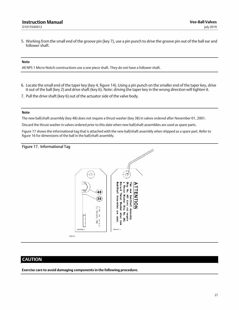
The new ball/shaft assembly (key 48) does not require a thrust washer (key 38) in valves ordered after November 01, 2001.
Discard the thrust washer in valves ordered prior to this date when new ball/shaft assemblies are used as spare parts.
Figure 17 shows the informational tag that is attached with the new ball/shaft assembly when shipped as a spare part. Refer tofigure 16 for dimensions of the ball in the ball/shaft assembly.
Figure 17. Informational Tag
29B9332
CAUTION
Exercise care to avoid damaging components in the following procedure.
Instruction ManualD101554X012
Vee-Ball ValvesJuly 2019
28
8. Make sure the sealing surface of the ball is not damaged while removing the follower shaft.
a. If a pipe plug (key 25) is installed, use a punch to drive the follower shaft (key 9) into the center of the ball.
b. If a pipe plug is not installed, use a piece of continuous threaded rod as a removal rod when moving the followershaft (key 9) into the center of the ball. Refer to the table 7 shown below for a description of the size threadedrod needed. The length of the rod should allow easy working room from the valve body.
9. Remove the ball (key 2) by carefully removing the follower shaft and ball from the valve body.
10. Remove the bearings (key 10) by hand. If the bearings are tight in the valve body, then pull or drive them out with aslight pressure.
11. Thoroughly clean surfaces of all parts that are to be re‐used or obtain replacement parts.
Assembly
1. Inspect all sealing surfaces to ensure they are in good condition and without scratches or wear.
2. Install bearings (key 10) by hand. The bearing flanged end should touch the body.
3. Installing the ball (key 2):
WARNING
The Vee‐Ball might be damaged if it is allowed to fall into the valve body. To avoid personal injury or damage to the sealingsurfaces, support the ball to prevent it from falling into or out of the valve body cavity.
Figure 18. Ball/Attenuator Installation and Removal Method
W6134
BALL/ATTENUATOR
Note
For ease of assembly, the follower shaft (key 9) should be inserted into the ball before installing the ball in an NPS 3 valve withoutball/attenuator

Instruction ManualD101554X012
Vee-Ball ValvesJuly 2019
29
Carefully install the ball into the valve body cavity.
After you have installed the ball (key 2) into the valve body assembly, firmly support the ball while installing the shafts.
4. Installing the follower shaft (key 9):
� For NPS 1 through 2 valves: The follower shaft (key 9) should already have been inserted into the ball before the ballwas put into the valve body. Insert the follower shaft (key 9) into the valve body bearing (key 10).
Note
All NPS 1 Micro‐Notch constructions use a one piece shaft. They do not have a follower shaft.
5. Installing the Drive Shaft for Valves with Taper Pins
CAUTION
The drive shaft must be used with the correct Vee‐Ball. Refer to the tag (see figure 13) attached to the Vee‐Ball and to thedrive shaft.
Failure to use the correct Vee‐Ball/ shaft combination may result in the ball not being in the position indicated by the slashmark on the end of the shaft. If the ball is not properly aligned with the slash mark, the valve will not function correctly andseal damage may result.
Figure 19. Location of Indicator Hole in Micro‐Notch Vee‐Balls
FOLLOWER END OF BALLSHAFT/ASSEMBLY
29B9552‐AE0764
INDICATOR HOLE
NOTCH
CAUTION
Make sure the drive shaft is free of oil or grease, otherwise the taper pin will not seat properly. Failure to properly set thetaper pin or taper key could result in it coming loose while in service. Loosening of the taper key in service could result inimproper valve function and equipment damage.

Instruction ManualD101554X012
Vee-Ball ValvesJuly 2019
30
6. Insert the drive shaft into the valve body bearing (key 10), and into the ball ear (or ball, for Micro‐Notchconstructions). Align the hole in the drive shaft with the holes in the ball.
Note
There is an indicator hole drilled in all Micro‐Notch balls. This indicator hole must be oriented closest to the follower end of theball/shaft assembly. See figure 19.
7. Insert the taper pin into the ball and drive shaft as shown in figures 20 and 21. The small end of the taper pin mustbe inserted into the larger hole side of the ball ear (or ball, for Micro‐Notch constructions), and into the large holeside of the drive shaft.
Note
The taper pin will not fit correctly if inserted in the wrong direction through the ball ear (or ball, for Micro‐Notch constructions) orthrough the drive shaft. Make sure the drive shaft and ball ear (or ball, for Micro‐Notch constructions) are in the correct orientationfor installing the pin.
� Installing Taper Pins in NPS 1, 1-1/2, and 2 Valves
Note
For NPS 1, 1-1/2, and 2 valves, the taper pins (figure 20) do not require welding.
Using a flat‐end punch, drive the taper pin into the ball ear (or ball, for Micro‐Notch constructions) and drive shaft untilsolid heavy contact is felt. Make sure the taper pin spans the width of the ball.
Using a flat end punch, drive the groove pin (key 7) into the ball and follower shaft until it is flat with the ball surface.
Installing the Drive Shaft in VTC Ceramic Vee‐Ball Valves
CAUTION
The drive shaft must be used with the correct Vee‐Ball. Refer to the tag (see figure 13) attached to the Vee‐Ball and to thedrive shaft.
Failure to use the correct Vee‐Ball/ shaft combination may result in the ball not being in the position indicated by the slashmark on the end of the shaft. If the ball is not properly aligned with the slash mark, the valve will not function correctly andseal damage may result.
Instruction ManualD101554X012
Vee-Ball ValvesJuly 2019
31
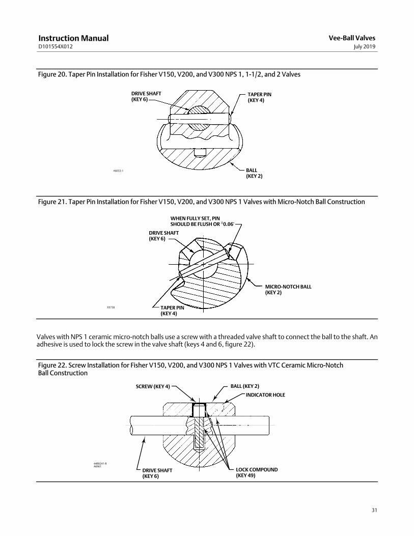
Figure 20. Taper Pin Installation for Fisher V150, V200, and V300 NPS 1, 1-1/2, and 2 Valves
A6033‐1
DRIVE SHAFT(KEY 6)
TAPER PIN(KEY 4)
BALL(KEY 2)
Figure 21. Taper Pin Installation for Fisher V150, V200, and V300 NPS 1 Valves with Micro‐Notch Ball Construction
E0738
DRIVE SHAFT(KEY 6)
WHEN FULLY SET, PINSHOULD BE FLUSH OR ±0.06'
TAPER PIN(KEY 4)
MICRO‐NOTCH BALL(KEY 2)
Valves with NPS 1 ceramic micro‐notch balls use a screw with a threaded valve shaft to connect the ball to the shaft. Anadhesive is used to lock the screw in the valve shaft (keys 4 and 6, figure 22).
Figure 22. Screw Installation for Fisher V150, V200, and V300 NPS 1 Valves with VTC Ceramic Micro‐Notch Ball Construction
SCREW (KEY 4) BALL (KEY 2)
DRIVE SHAFT(KEY 6)
LOCK COMPOUND(KEY 49)
44B0241‐BA6961
INDICATOR HOLE

Instruction ManualD101554X012
Vee-Ball ValvesJuly 2019
32
Note
There is an indicator hole drilled in all Micro‐Notch balls. The orientation of this hole in the ceramic Vee‐Ball is to the right of thescrew in the ball, and must be located closest to the follower end of the ball/shaft assembly. See figures 19 and 22.
WARNING
Avoid personal injury and property damage from ignition of process fluid caused by sparks from ceramic trim.
Do not use ceramic trim where the process fluid is unstable or if it is an explosive mixture (such as ether and air).
Within the valve body:
8. The threaded hole in the shaft, the screw and screw clearance hole in the ball must be free of oil and grease beforeapplying an activator.
9. Apply Loctite� Depend� Activator 7387 to threaded hole, screw and ball clearance hole. Assemble the ball onto theshaft while aligning threaded shaft hole within the ball clearance hole.
10. The flat on the shaft must be oriented so that the head of the cap screw seats on the flat.
11. Apply 5 drops of Loctite Depend 330 into the hole in the ball.
12. Thread the screw into the shaft tightening it to 9.2 N�m (81 in�lbs) torque. Remove excess adhesive, Allow fourhours to cure fully before continuing with assembly.
For all constructions: Refer to Replacing the Ball Seal, Packing Maintenance, and other procedures as necessary tocomplete the assembly of the valve.
Cavitrol Hex InstallationThe Cavitrol Hex anti-cavitation trim (key 64) is available for the NPS 4 through 12, V150, V300, and V200 flanged,raised-face body constructions. To retrofit the Cavitrol Hex to an existing valve assembly, special body machining isrequired. Two threaded holes must be added to the valve body outlet flange. Contact your Emerson sales office forretrofit information.
Note
The Cavitrol Hex anti-cavitation trim will add 0.5 inch to the face to face dimension of the valve. Refer to table 3 of this manual forinformation on required flange stud length.
The standard Cavitrol Hex is compatible with the counter clockwise (CCW) to close ball design. Contact your Emersonsales office for information on Cavitrol Hex compatibility with the special clockwise (CW) to close ball design.
Assembly1. The Cavitrol Hex anti-cavitation trim (key 64) is to be installed last, after the Vee-Ball valve body assembly is
complete. The recommended valve orientation for assembly is with the body outlet flange facing up.
2. Ensure the ball is in the open position.
3. Place the gasket (key 65) over the body outlet flange serrated surface as illustrated in figure 28.

Instruction ManualD101554X012
Vee-Ball ValvesJuly 2019
33
4. Insert the Cavitrol Hex anti-cavitation trim into the valve, ensuring the holes in the body outlet flange align with theholes in the trim flange.
5. Install two fasteners (key 21) and adequately tighten to secure the trim to the valve assembly.
Actuator MountingUse the appropriate actuator instruction manual, this section of this manual, and figure 23 of this manual whenmounting the actuator or changing actuator styles and positions.
1. To help ensure correct centering of the Vee‐Ball (key 2) on the seal (key 11), be sure the ball is closed whenmounting the actuator (for applications other than Spring Return Fail‐Open).
2. Clean the valve shaft and actuator lever splines to be sure the actuator lever will slide on easily. Only drive the leverin if absolutely necessary.
3. Carefully wedge the ball solidly against the actuator‐side bearing, using a screwdriver or similar tool insertedbetween the lower ear of the ball and the valve body. This will center the ball. See figure 6.
4. Keep the wedge in place while installing the lever, if necessary. Remove the wedge after you have clamped theactuator lever on the valve shaft and have connected the lever to the actuator piston rod or diaphragm rod.
Determining Mounting PositionThe actuator can be either right or left‐hand mounted, with the actuator on the right or left side when viewed fromupstream (see figure 23).
The Series B Vee‐Ball, NPS 4 through 12 with attenuator, and the NPS 1 micro‐notch Vee‐Ball have one V‐notch. Forright‐hand mounting (standard), the ball will be in the top of the valve body when the valve is open and the shaft ishorizontal. In this position the ball rotates CCW to Close. For left‐hand mounting (standard), the ball will be in thebottom of the valve body when the valve is open and the shaft is horizontal. In this position the ball rotates CCW toClose. An optional ball for left‐hand mounting, which rotates into the top of the valve body when the shaft ishorizontal, is also available. In this position the ball rotates CW to Close.
The NPS 1 through 2 has two notches, and can be rotated in either direction.
Determining Closed Position1. The valve must be removed from the line to check the position of the ball.
WARNING
The Vee‐Ball closes with a shearing, cutting motion. To avoid personal injury, keep hands, tools, and other objects awayfrom the ball while stroking the valve.
2. Rotate the ball to the closed position.
3. Position the ball in the proper location
For Series B:
� When viewed from the valve body inlet, the ball is in the proper position when the flat spot on the top of the ball isexactly in the center of the seal package.
Make a copy of the centering template in figure 27 out of a suitable stiff material. Place the centering template in theopening at the seal (See figure 27). Find the center of the template and make sure the spot on the ball is centereddirectly below it.

Instruction ManualD101554X012
Vee-Ball ValvesJuly 2019
34
For NPS 1, 1-1/2, and 2 valves: Follow one of the procedures below:
� When viewed from the valve body inlet, the ball is in the proper position when both V‐notches of the ball arecentered between the machined diameter of the ledge that supports the seal.
� If the ball has a spot machined on the top, align that spot to the exact center of the seal cavity.
4. Adjust the actuator linkage as described in the appropriate actuator instruction manual until the ball is centered inthe closed position. A line is stamped on the actuator end of the drive shaft (see figure 23) to indicate the ballposition.
Use the appropriate actuator instruction manual and figure 23 of this manual when mounting the actuator orchanging actuator styles and positions.
The Micro‐Notch ball closed position is approximately 5 degrees closed from the first point of flow. This establishes thezero degree position for the ball.

Instruction ManualD101554X012
Vee-Ball ValvesJuly 2019
35
Figure 23. Index Marks for Actuator Lever Orientation for NPS 1 through 12 Valves with or without Attenuator
48B4773‐C
NOTE:1. ARROW ON LEVER INDICATES DIRECTION OF ACTUATOR THRUST TO CLOSE VALVE.2. THE OPTIONAL LEFT-HAND ORIENTATION IS NOT AVAILABLE FOR MICRO-NOTCH VEE-BALLS.
(2)

Instruction ManualD101554X012
Vee-Ball ValvesJuly 2019
36
Figure 24. Fisher V150 or V300 (NPS 3 - 12) or Flanged V200 (NPS 3 - 8) Valve Assembly (Details are typical for V200 Flangeless valve body)
58B2296‐D
ALLOYFOLLOWER NPS 10 & 12
HD SEALFOR ATTENUATOR
USE ONLY
LEAKOFFFOLLOWER
FLAT METAL SEAL
TCM SEAL
PIPE PLUG
PARTS NOT SHOWN: 28, 30, 31, 32, 35 & 36
ATTENUATOR BALLNPS 4‐12

Instruction ManualD101554X012
Vee-Ball ValvesJuly 2019
37
Figure 25. Exploded View, Fisher V150 and V300 (NPS 3 - 12) and Flanged V200 (NPS 3-8) without AttenuatorAssembly.
1
2
3
4
6
79
27
26
23
16
19
20
39
24
23
17
21
22
15
11
10
Instruction ManualD101554X012
Vee-Ball ValvesJuly 2019
38
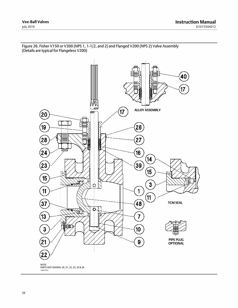
Figure 26. Fisher V150 or V300 (NPS 1, 1-1/2, and 2) and Flanged V200 (NPS 2) Valve Assembly(Details are typical for Flangeless V200)
44B2228‐B
ALLOY ASSEMBLY
TCM SEAL
PIPE PLUGOPTIONAL
NOTE:PARTS NOT SHOWN: 30, 31, 32, 33, 35 & 36

Instruction ManualD101554X012
Vee-Ball ValvesJuly 2019
39
Figure 27. Centering Template in Use and Template Dimensions
19B8493E0740
19B8493E0741
VALVE SIZE,DN
VALVE SIZE,NPS
A(FOR ASME VALVES)
A(FOR DIN VALVES)
B(1)C(1)
(ANSI/ISAS75.08.02)
C(ASME B16.10 Short(2))
D(1)
mm
25 1 63 68 19 35 61 25
40 1-1/2 82 88 28 34 85 25
50 2 102 102 38 31 85 25
80 3 127 138 63 24 62 38
100 4 157 157 82 36 71 44
150 6 216 212 117 21 59 51
200 8 270 268 139 12 61 57
250 10 324 320 203 2 35 60
300 12 381 378 254 2 20 63
Inches
25 1 2.50 2.68 0.75 1.40 2.40 1.00
40 1-1/2 3.25 3.46 1.12 1.34 3.34 1.00
50 2 4.02 4.02 1.50 1.22 3.34 1.00
80 3 5.00 4.55 2.50 0.94 2.44 1.50
100 4 6.19 6.19 3.25 1.42 2.80 1.75
150 6 8.50 8.35 4.62 0.82 2.32 2.00
200 8 10.62 10.55 5.50 0.48 2.42 2.25
250 10 12.75 12.60 8.00 0.09 1.40 2.38
300 12 15.00 14.88 10.00 0.09 0.78 2.50
1. These dimensions are the same for ASME and DIN valves.2. Note that ASME B16.10 Short dimensions are actually longer than ANSI/ISA S75.08.02 dimensions.

Instruction ManualD101554X012
Vee-Ball ValvesJuly 2019
40
Parts OrderingA serial number is assigned to each valve and stamped on the nameplate. Always refer to the valve serial number whencorresponding with your Emerson sales office regarding spare parts or technical information. When orderingreplacement parts, also specify the key number, part name, and desired material using the parts list.
WARNING
Use only genuine Fisher replacement parts. Components that are not supplied by Emerson Automation Solutions shouldnot, under any circumstances, be used in any Fisher valve, because they will void your warranty, might adversely affect theperformance of the valve, and could give rise to personal injury and property damage.
Note
For the NPS 2 V150 valve, this manual covers valves with serial numbers 12551183 and higher. Always reference the serial numberof your valve when corresponding with your Emerson sales office.
Retrofit Kits for ENVIRO‐SEAL PackingRetrofit kits include parts to convert existing V150, V200 and V300 valves with shallow (single packing depth) packingbox to the ENVIRO‐SEAL packing box construction. Retrofit kits include single PTFE packing. See following table.
ENVIRO‐SEAL Packing Retrofit KitsSHAFT DIAMETER(1) PART NUMBER
mm Inches Single PTFE Graphite
12.7 1/2 RRTYXRT0012 RRTYXRT0312
15.9 5/8 RRTYXRT0022 RRTYXRT0322
19.1 3/4 RRTYXRT0032 RRTYXRT0332
25.4 1 RRTYXRT0052 RRTYXRT0352
31.8 1‐1/4 RRTYXRT0062 RRTYXRT0362
38.1 1‐1/2 RRTYXRT0072 RRTYXRT0372
Parts Included in Kit
Key Description Quantity
100 Packing stud 2 2
101 Packing nut 2 2
102 Packing flange 1 1
103 Spring pack assembly 1 1
105 Packing set 1 1
106 Anti-extrusion washer 2 ‐ ‐ ‐
107 Packing box ring(2) 1 1
‐ ‐ ‐ Tag 1 1
‐ ‐ ‐ Tie Cable 1 1
1. Diameter through the packing box.2. Not required for all sizes of V150 and V200 or for V300 with 1‐1/4 or 1‐1/2 inch diameter shafts.

Instruction ManualD101554X012
Vee-Ball ValvesJuly 2019
41
Figure 28. Fisher V300 with Cavitrol Hex Explosion View
GE96725
65
64
21
Figure 29. Fisher V300 with Cavitrol Hex Assembly View
GE96724
SCALE 1.25:1

Instruction ManualD101554X012
Vee-Ball ValvesJuly 2019
42
Repair Kits for ENVIRO‐SEAL PackingRepair kits include valves parts for shallow (single packing depth) for ENVIRO‐SEAL packing box construction. Repairkits include single PTFE or graphite packing. See following table.
ENVIRO‐SEAL Packing Repair KitsSHAFT DIAMETER(1) PART NUMBER
mm Inches PTFE Graphite
12.7 1/2 RRTYX000012 13B8816X012
15.9 5/8 RRTYX000022 13B8816X032
19.1 3/4 RRTYX000032 13B8816X052
25.4 1 RRTYX000052 13B8816X092
31.8 1‐1/4 RRTYX000062 13B8816X112
38.1 1‐1/2 RRTYX000072 13B8816X142
Parts Included in Kit
Key Description Quantity
105 Packing set 1 1
106 Anti‐extrusion washer 2 ‐ ‐ ‐(2)
1. Diameter through the packing box.2. Included in key 105.
Repair Kits for Ball SealsSeal repair kits include recommended spare parts for Fisher TCM Plus, S31600 stainless steel, CF10SMnN, orCD7MCuN ball seal constructions. The following table indicates the repair kit part number and the quantity of partsincluded in the kit.
Fisher V150, V200, and V300 Repair Kits
VALVE SIZEKIT PART NUMBER
Ball Seal Material
DN NPS TCM Plus - - - Alloy 6CD7MCuN
(Alloy 255 Duplex SST)
2540
11-1/2
RV150X00CA2RV150X00CB2
‐ ‐ ‐‐ ‐ ‐
RV150XHDAA2RV150XHDAB2
RV150XHDCA2RV150XHDCB2
VALVE SIZE Ball Seal Material
DN NPS TCM PlusS31600
(316 SST)CF10SMnN
CD7MCuN(Alloy 255 Duplex SST)
505080
100150200250300
2(1)
2(2)
3468
1012
RV150X00C12RV150X00C82RV150X00C22RV150X00C32RV150X00C42RV150X00C52RV150X00C62RV150X00C72
RV150X00M12‐ ‐ ‐
RV150X00M22RV150X00M32RV150X00M42RV150X00M52RV150X00M62RV150X00M72
RV150X0HD12RV150X0HD82RV150X0HD22RV150X0HD32RV150X0HD42RV150X0HD52RV150X0HD62RV150X0HD72
RV150XHDC12RV150XHDC82RV150XHDC22RV150XHDC32RV150XHDC42RV150XHDC52RV150XHDC62RV150XHDC72
Parts Included in KitQuantity in Kit
Key No. Description
11121313
Ball sealShim seal(3)
Spring sealWave spring
1‐ ‐ ‐‐ ‐ ‐‐ ‐ ‐
141
‐ ‐ ‐
1‐ ‐ ‐‐ ‐ ‐1
1‐ ‐ ‐‐ ‐ ‐1
15372122
GasketRadial seal
Retainer screwRetainer washer
1‐ ‐ ‐
2 or 4(4)
2 or 4(4)
1‐ ‐ ‐
2 or 4(4)
2 or 4(4)
11
2 or 4(4)
2 or 4(4)
11
2 or 4(4)
2 or 4(4)
1. V150’s only for serial numbers below 12551183.2. V150’s for serial numbers 12551183 and above. All V200’s and V300’s.3. Fewer shim seals are furnished in the parts kits than are used in the original construction of the valve. Most original shim seals can be reused.4. A quantity of 2 is supplied for NPS 2 through 8 valves, and a quantity of 4 is supplied for NPS 10 and 12 valves.

Instruction ManualD101554X012
Vee-Ball ValvesJuly 2019
43
Cavitrol Hex Retrofit KitKit includes the Cavitrol Hex (key 64), gasket (key 65), and fasteners (key 21). Kits are available for the NPS 4 through12 V150, V300, and V200 flanged, raised-face body constructions. To retrofit the Cavitrol Hex anti-cavitation trim toan existing valve assembly, special body machining is required. Two threaded holes must be added to the valve bodyoutlet flange. Contact your Emerson sales office for retrofit information.
Fisher V150, V200(1), and V300 Cavitrol Hex Kits
VALVE SIZE,NPS
KIT PART NUMBER
Material
S31603 (316L) R31233 (Ultimet)
4 RCAVHEX0002 RCAVHEX0012
6 RCAVHEX0022 RCAVHEX0032
8 RCAVHEX0042 RCAVHEX0052
10 RCAVHEX0062 RCAVHEX0072
12 RCAVHEX0082 RCAVHEX0092
1. V200 raised face flanged body.

Instruction ManualD101554X012
Vee-Ball ValvesJuly 2019
44
Parts List
Note
Contact your Emerson sales office for Part Ordering information.
Common Parts(figures 24, 25 & 26)Key Description
1 If you need a valve body as a replacement part, order by valve
size, serial number, and desired valve body material. Contact your
Emerson sales office for assistance.
2* Ball
2* Ball w/ attenuator
3 Seal Protector Ring
4* Taper Key
6* Drive Shaft
6* Drive Shaft w/ attenuator
7* Groove Pin
9* Follower Shaft
9* Follower Shaft w/ attenuator
10* Bearing (2 req'd)
11* Ball Seal
12* Shim Seal (12 req'd)
Use w/flat metal seal only
13* Spring Seal
Use w/ flat metal seal only
13* Wave Spring
use w/ HD Metal Seal only
14 Backup Ring (Composition seal only)
Key Description
15* Gasket
16* Packing Set
17 Packing Follower w/integral flange
17 Packing Follower w/o integral flange
19 Packing Follower Stud
20 Packing Follower Nut
21 Seal Protector Screw
22 Seal Protector Clip
23 Actuator Mounting Screw
24 Actuator Mounting Nut
25 Pipe Plug (Optional) (not shown)
26 Identification Nameplate
27 Drive Screw
28 Flow Arrow
30 Nameplate
31 Nameplate Wire (not shown)
32 Line Flange Stud
33 Line Flange Stud
34 Spacer
35* Packing Ring (4 req'd)
36* Packing Washer
37* Radial Seal
Use w/HD Metal Seal
39* Packing Box Ring
40 Packing Flange
41 Retaining Ring
48* Ball‐Shaft Assembly
64 Cavitrol Hex
65 Gasket
130 Clamp
131 Bonding Strap Assembly
ENVIRO‐SEAL Packing System(Parts in all Type Vee‐Ball Valves)(figure 5)Key Description
100 Packing Flange Stud
101 Packing Flange Nut
102 Packing Flange
103 Spring Pack Assembly
105* Packing Set
106* Anti‐Extrusion Ring (2 req'd)
107* Packing Box Ring
108* Packing Ring (2 req'd)
109* Anti‐Extrusion Ring (2 req'd)
110 Lantern Ring
111 Tag
112 Tie Cable
113 Lubricant, anti‐seize (not furnished with packing system)
*Recommended spare parts

Instruction ManualD101554X012
Vee-Ball ValvesJuly 2019
45
Appendix A Instructions for Non‐Series BThe Series B changes affected only the NPS 3 through 12 valves without attenuators. To determine if a Vee‐Ball valve isSeries B, you will need to examine several of the internal parts. Compare the distinctive skirted V‐notch outline of theforward side and the circular edge on the reverse side of the Series B design ball to the V‐notch on both sides of thenon‐series B design ball. Then look for bushings. The lack of bushings indicates the valve body is Series B.
All Vee‐Ball valves NPS 3 through 12 produced before the Series B design changes use the Specifications table, theInstallation, Maintenance, Packing Maintenance, Replacing Packing, and Replacing the Ball Seal instructions foundelsewhere in this manual. Bearing and Vee‐Ball Maintenance and Actuator Mounting instructions for these valves maybe found below.
Maintenance
WARNING
The Vee‐ball closes with a shearing, cutting motion, which could result in personal injury. To avoid injury, keep hands,tools, and other objects away from the Vee‐ball while stroking the valve.
Avoid personal injury from sudden release of process pressure. Before performing any maintenance operations:
� Do not remove the actuator from the valve while the valve is still pressurized.
� Disconnect any operating lines providing air pressure, electric power, or a control signal to the actuator. Be sure theactuator cannot suddenly open or close the valve.
� Use bypass valves or completely shut off the process to isolate the valve from process pressure. Relieve process pressurefrom both sides of the valve. Drain the process media from both sides of the valve.
� Vent the power actuator loading pressure and relieve any actuator spring precompression.
� Use lock‐out procedures to be sure that the above measures stay in effect while you work on the equipment.
� Always wear protective gloves, clothing, and eyewear when performing any maintenance operations to avoid personalinjury.
� The valve packing area may contain process fluids that are pressurized, even when the valve has been removed from thepipeline. Process fluids may spray out under pressure when removing the packing hardware or packing rings.
� Check with your process or safety engineer for any additional measures that must be taken to protect against processmedia.
Procedures for disassembly and assembly of the bearings and ball cannot be accomplished until the ball seal and valvepacking are removed from the valve.
1. Refer to the Replacing Packing procedures to remove the actuator, and to remove the packing flange and packingfollower from the valve. When the packing disassembly steps are complete, return to this section.
2. Refer to the Replacing the Ball Seal procedures to remove the ball seal from the valve.
Disassembly
WARNING
When the actuator is removed from the valve, the ball/shaft assembly may suddenly rotate, with a shearing, cuttingmotion, which could result in personal injury. To avoid injury, carefully rotate the ball to a stable position. Make sure theball will not rotate.

Instruction ManualD101554X012
Vee-Ball ValvesJuly 2019
46
Key numbers in this procedure are shown in figures 24, 26, and 32, unless otherwise indicated. A taper key (key 4,figure 14) is used in NPS 3 through 12 Non‐Series B valves.
3. Carefully rotate the ball to the open position after the actuator is disconnected. Make sure the ball will not rotate(see warning above). Provide support for the ball during the following disassembly.
4. Unscrew the pipe plug (key 25). (With newer valve constructions, the pipe plug is optional and may not beavailable.)
5. Working from the small end of the groove pin (key 7), use a pin punch to drive the groove pin out of the ball ear andfollower shaft.
For tack welded taper keys, driving the taper key out of the ball ear will shear the tack welding.
6. Locate the small end of the taper key (key 4, see figure 14). Using a pin punch on the smaller end of the taper key,drive it out of the ball (key 2) and drive shaft (key 6). Note: driving the taper key in the wrong direction will tightenit.
7. Pull the drive shaft (key 6) out of the actuator side of the valve body.
8. Make sure the sealing surface of the ball is not damaged while removing the follower shaft.
a. If a pipe plug (key 25) is installed, use a punch to drive the follower shaft (key 9) into the center of the ball.
b. If a pipe plug is not installed, use a piece of continuous threaded rod as a removal rod when moving the followershaft (key 9) into the center of the V‐notch ball. Refer to the table 8 for a description of the size threaded rodneeded. The length of the rod should allow easy working room from the valve body.
9. Remove the ball (key 2) by carefully removing the follower shaft and ball from the valve body.
10. Remove the packing box spacer (key 34) for NPS 8, 10, and 12 valves.
11. Removing the bearings (key 10):
a. For composition bearings, remove the bearings by hand. If the bearings are tight in the valve body, then pull ordrive them out with a slight pressure. Allow the bushings (key 5 or 8) to remain in the valve body.
Table 8. Continuous Threaded RodValve Size, NPS Threaded Rod Thread Size Thread Depth in Follower Shaft
3 1/4‐20 0.5
4 1/4‐20 0.5
6 1/4‐20 0.5
8 5/16‐18 0.62
10 5/16‐18 0.62
12 5/16‐18 0.94
b. For metal bearings, use a press and ram to remove the drive shaft bearings out of the valve body. Refer to figures30 and 31 ram dimensions. The bushings (key 5 or 8) will normally remain in the valve body.
To remove the follower shaft bearings, use a blind‐hole bearing puller. If you do not have such a tool, you can machinethe bearing out.
Note
For proper shutoff performance, the ball and seal require the bearing (key 10) to be positioned correctly. If you removed thebearings (key 10), be sure to locate the new bearings as shown in figures 30 and 31.
12. Thoroughly clean surfaces of all parts that are to be re‐used or obtain replacement parts.

Instruction ManualD101554X012
Vee-Ball ValvesJuly 2019
47
Assembly1. Inspect all sealing surfaces to ensure they are in good condition and without scratches or wear.
2. Installing bearings (key 10):
a. For composition bearings, install the bearings by hand. The bearing flanged end should touch the bushing (key 5or 8).
b. For metal bearings:
� Use a press and ram to install the bearings (key 10). Refer to figures 30 and 31.
� Press the bearings in until each bearing is flush with the bushing (key 5 or 8). The acceptable tolerance for bearinglocation is: flush with the bushing to 1.52 mm (0.060 inches) inside the bushing. That is, the bearings should notprotrude into the flow cavity of the valve, and they should not be more than 1.52 mm (0.060 inches) inside thebushing.
� Take care not to change the position of the bushings (key 5 or 8) when pressing in new bearings (key 10), otherwisethe ball will not center in the valve body and seal.
3. Installing the Vee‐Ball (key 2):
WARNING
The Vee‐Ball might be damaged if it is allowed to fall into the valve body. To avoid personal injury or damage to the sealingsurfaces, support the ball to prevent it from falling into or out of the valve body cavity.
Note
For ease of assembly, the follower shaft (key 9) should be inserted into the ball before installing the ball in an NPS 3 valve withoutball/attenuator.
Carefully install the ball into the valve body cavity.
After you have installed the ball (key 2) into the valve body assembly, firmly support the ball while installing the shafts.
4. Installing the follower shaft (key 9):
� For NPS 3 valves: The follower shaft (key 9) should already have been inserted into the ball before the ball was putinto the valve body. Insert the follower shaft (key 9) into the valve body bearing (key 10).
� For NPS 4 and larger valves without attenuator: Insert the follower shaft (key 9) through the ball, and into the valvebody bearing (key 10).
Then for all sizes, align the hole in the follower shaft with the holes in the ball. Insert the small end of the groove pin(key 7) into the hole in the ball and into the follower shaft. The pin will hold the parts in place while the drive shaft (key6) is being installed.
5. Insert the drive shaft (key 6) into the valve body bearing (key 10), and into the ball ear. Align the hole in the driveshaft with the holes in the ball.
CAUTION
The drive shaft must be used with the correct Vee‐Ball. Refer to the tag (see figure 13) attached to the Vee‐Ball and to thedrive shaft.
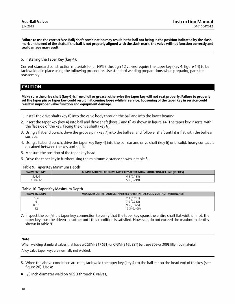
Instruction ManualD101554X012
Vee-Ball ValvesJuly 2019
48
Failure to use the correct Vee‐Ball/ shaft combination may result in the ball not being in the position indicated by the slashmark on the end of the shaft. If the ball is not properly aligned with the slash mark, the valve will not function correctly andseal damage may result.
6. Installing the Taper Key (key 4):
Current standard construction materials for all NPS 3 through 12 valves require the taper key (key 4, figure 14) to betack welded in place using the following procedure. Use standard welding preparations when preparing parts forreassembly.
CAUTION
Make sure the drive shaft (key 6) is free of oil or grease, otherwise the taper key will not seat properly. Failure to properlyset the taper pin or taper key could result in it coming loose while in service. Loosening of the taper key in service couldresult in improper valve function and equipment damage.
1. Install the drive shaft (key 6) into the valve body through the ball and into the lower bearing.
2. Insert the taper key (key 4) into ball and drive shaft (keys 2 and 6) as shown in figure 14. The taper key inserts, withthe flat side of the key, facing the drive shaft (key 6).
3. Using a flat end punch, drive the groove pin (key 7) into the ball ear and follower shaft until it is flat with the ball earsurface.
4. Using a flat end punch, drive the taper key (key 4) into the ball ear and drive shaft (key 6) until solid, heavy contact isobtained between the key and shaft.
5. Measure the position of the taper key head.
6. Drive the taper key in further using the minimum distance shown in table 8.
Table 9. Taper Key Minimum DepthVALVE SIZE, NPS MINIMUM DEPTH TO DRIVE TAPER KEY AFTER INITIAL SOLID CONTACT, mm (INCHES)
3, 4, 68, 10, 12
4.8 (0.188)5.6 (0.219)
Table 10. Taper Key Maximum DepthVALVE SIZE, NPS MAXIMUM DEPTH TO DRIVE TAPER KEY AFTER INITIAL SOLID CONTACT, mm (INCHES)
3, 46
8, 1012
7.1 (0.281)7.9 (0.312)9.5 (0.375)
10.3 (0.406)
7. Inspect the ball/shaft taper key connection to verify that the taper key spans the entire shaft flat width. If not, thetaper key must be driven in further until this condition is satisfied. However, do not exceed the maximum depthsshown in table 9.
Note
When welding standard valves that have a CG8M (317 SST) or CF3M (316L SST) ball, use 309 or 309L filler rod material.
Alloy valve taper keys are normally not welded.
8. When the above conditions are met, tack weld the taper key (key 4) to the ball ear on the head end of the key (seefigure 26). Use a:
� 1/8 inch diameter weld on NPS 3 through 6 valves,

Instruction ManualD101554X012
Vee-Ball ValvesJuly 2019
49
� 3/16 inch diameter weld on NPS 8 through 10 valves, and
� 1/4 inch diameter weld on NPS 12 valves.
For all constructions: Refer to Replacing the Ball Seal, Packing Maintenance, and other procedures as necessary tocomplete the assembly of the valve.
Actuator MountingUse the appropriate actuator instruction manual and figure 23 of this manual when mounting the actuator orchanging actuator styles and positions.
To help ensure correct centering of the ball (key 2) on the seal (key 11), be sure the ball is closed when mounting theactuator. Do not use a hammer or other tool to drive the actuator lever onto the valve shaft.
Clean the valve shaft and actuator lever splines to be sure the actuator lever will slide on easily. If the lever does notslide on easily, carefully wedge the ball solidly against the actuator‐side bearing using a screwdriver or similar toolinserted between the lower ear of the ball and the valve body.
Keep the wedge in place while installing the lever, but again, do not drive on the lever. Remove the wedge after youhave clamped the actuator lever on the valve shaft and connected the lever to the actuator piston rod or diaphragmrod.
Determining Mounting Position
The actuator can be either right or left‐hand mounted.
Note
Right‐hand mounting—Actuator is on the right side of the valve when viewed from valve inlet.
Left‐hand mounting—Actuator is on the left side of the valve when viewed from valve inlet.
The preferred location of the ball is in the top of the valve body when the valve is open. To convert from right to lefthand‐mounting, turn the valve to position the actuator mounting pad on the left and rotate the ball to the top of thevalve.
The number one V‐notch controls flow on right‐hand mounting. Turn the valve 180 degrees, and rotate the ball to thetop of the valve to obtain left‐hand mounting. The number two V‐notch controls flow for this construction. See figure33.
Determining Closed Position1. The valve must be removed from the line to check the position of the ball.
WARNING
The ball closes with a shearing, cutting motion. To avoid personal injury, keep hands, tools, and other objects away fromthe ball while stroking the valve.

Instruction ManualD101554X012
Vee-Ball ValvesJuly 2019
50
2. Rotate the ball to the closed position.
3. Follow one of the procedures below:
� When viewed from the valve body inlet, the ball is in the proper position when both V‐notches of the ball arecentered between the machined diameter of the ledge that supports the seal.
� If the ball has a spot machined on the top, align that spot to the exact center of the seal cavity.
4. Adjust the actuator linkage as described in the appropriate actuator instruction manual until the conditiondescribed in step 3 exists. A line is stamped on the actuator end of the drive shaft (see figure 23) to indicate the ballposition.
WARNING
Use only genuine Fisher replacement parts. Components that are not supplied by Emerson Automation Solutions shouldnot, under any circumstances, be used in any Fisher valve, because they will void your warranty, might adversely affect theperformance of the valve, and could give rise to personal injury and property damage.
Non‐Series B Design Parts (figure 32)
Note
Contact your Emerson sales office for Part Ordering information.
Key Description
2 Ball
2 Ball with attenuator (RH mtg in Common parts section)
6 Drive Shaft
9 Follower Shaft
10* Bearing (2 req'd)
*Recommended spare parts

Instruction ManualD101554X012
Vee-Ball ValvesJuly 2019
51
VALVESIZE,NPS
BEARING RAM DIMENSIONS BUSHING RAM DIMENSIONS
Ram Lengths Ram Diameters Ram Diameters
L M D d D Long Ram d Short Ram d
mm Inches mm Inches mm Inches mm Inches mm Inches mm Inches mm Inches
3 & 4201.42
MIN7.930MIN(1)
95.25MIN
3.750MIN
22.8622.61
0.9000.890
19.0518.80
0.7500.740
28.1927.94
1.1101.100
19.0518.80
0.7500.740
22.8622.61
0.9000.890
6247.65
MIN9.750MIN
95.25MIN
3.750MIN
29.2128.96
1.1501.140
25.4025.15
1.0000.990
34.5434.29
1.3601.350
25.4025.15
1.0000.990
29.2128.96
1.1501.140
8338.75
MIN13.310
MIN139.70
MIN5.500MIN
35.5635.31
1.4001.390
31.7531.50
1.2501.240
40.8940.64
1.6101.600
31.7531.50
1.2501.240
35.5635.31
1.4001.390
10396.75
MIN15.620
MIN139.70
MIN5.500MIN
35.5635.31
1.4001.390
31.7531.50
1.2501.240
40.8940.64
1.6101.600
31.7531.50
1.2501.240
35.5635.31
1.4001.390
12476.25
MIN18.750
MIN152.40
MIN6.000MIN
41.9141.66
1.6501.640
38.1037.85
1.5001.490
50.4250.17
1.9851.975
38.1037.85
1.5001.490
41.9141.66
1.6501.640
1. MIN = Minimum.
VALVESIZE,NPS
DIMENSION
B C B C
Millimeters Inches
348.2650.04
100.38100.63
1.9601.970
3.9523.962
460.1060.35
121.01121.26
2.3662.376
4.7644.774
683.5983.85
168.00168.25
3.2913.301
6.6146.624
8106.20106.45
213.21213.46
4.1814.191
8.3948.404
10135.33135.59
271.48271.73
5.3285.338
10.68810.698
12169.67169.93
340.16340.41
6.6806.690
13.39213.402
Figure 30. Bushing Location
DIA A
A/2 B
C
BUSHING (KEY 5) LOCATION
A5684‐1
Figure 31. Metal Bearing Ram Location
NPS 3 THRU 12VIEW A
SHORTRAM
SEE VIEW A
LONGRAM
BUSHING(KEY 5 OR 8)
BEARING(KEY 10)
1.520.000(0.0600.000)
D
M
LONG RAM
SHORT RAMD
L
6.35(0.25)
d
d
mm(INCHES)
BEARING RAMNOTES:
DIMENSION B IS THE DISTANCE BETWEEN THEGUIDE BUSHING AND THE CENTER OF DIAMETER A.1
A5683‐2
6.35(0.25)

Instruction ManualD101554X012
Vee-Ball ValvesJuly 2019
52
Figure 32. Fisher V150 and V300 Non‐Series B Valve Assembly (NPS 3- 12)(Details are typical for V200 Valves except V200 does not have flanges)
METAL BEARINGNPS 3‐6
PEEK BEARINGNPS 8, 10, & 12
METALBEARING
NPS 8, 10 & 12
ALLOY ASSEMBLY
ATTENUATOR BALLNPS 4‐12
FLAT METAL SEAL
TCM SEAL
HD METAL SEALNPS 10 & 12
NOTE:KEYS 28, 30, 31, 32, 35, AND 36 ARE NOT SHOWN.
42B4652‐C

Instruction ManualD101554X012
Vee-Ball ValvesJuly 2019
53
Figure 33. Index Marks for Actuator Lever Orientation for Non‐Series B Valves
ACTUATORVALVE OPEN
ACTUATOR POSITION
MOUNTING STYLE 1 2 3 4
RIGHT‐HAND(1)
STYLE A
STYLE B
STYLE C
STYLE D
LEFT‐HAND(1)
(PDTC)(2)
(PDTO)(2)
(PDTC)(2)
(PDTO)(2)
(3)
1. Right‐hand mounting controls with v notch no. 1; Left‐hand mounting controls with v notch no. 22. PDTC‐push down to close; PDTO‐push down to open3. Arrow on lever indicates direction of actuator thrust to close valve
B2703

Instruction ManualD101554X012
Vee-Ball ValvesJuly 2019
54

Instruction ManualD101554X012
Vee-Ball ValvesJuly 2019
55
Instruction ManualD101554X012
Vee-Ball ValvesJuly 2019
56
Emerson Automation SolutionsMarshalltown, Iowa 50158 USASorocaba, 18087 BrazilCernay, 68700 FranceDubai, United Arab EmiratesSingapore 128461 Singapore
www.Fisher.com
The contents of this publication are presented for informational purposes only, and while every effort has been made to ensure their accuracy, they are notto be construed as warranties or guarantees, express or implied, regarding the products or services described herein or their use or applicability. All sales aregoverned by our terms and conditions, which are available upon request. We reserve the right to modify or improve the designs or specifications of suchproducts at any time without notice.
� 1990, 2019 Fisher Controls International LLC. All rights reserved.
Fisher, ENVIRO-SEAL, Vee-Ball, Cavitrol, and FIELDVUE are marks owned by one of the companies in the Emerson Automation Solutions business unit ofEmerson Electric Co. Emerson Automation Solutions, Emerson, and the Emerson logo are trademarks and service marks of Emerson Electric Co. All othermarks are the property of their respective owners.
Neither Emerson, Emerson Automation Solutions, nor any of their affiliated entities assumes responsibility for the selection, use or maintenanceof any product. Responsibility for proper selection, use, and maintenance of any product remains solely with the purchaser and end user.