fiscal year 2016 through 2020 bridge preservation and ...€¦ · chapter 5 - bridge...
TRANSCRIPT

BRIDGE OFFICE MINNESOTA DEPARTMENT OF TRANSPORTATION
Fiscal Year 2016 through 2020 Bridge Preservation and Improvement Guidelines
Beverly Farraher Date Acting State Bridge Engineer
Approved

Table of Contents Page
MNDOT BRIDGE ASSET MANAGEMENT ................................................................................................................. 1 CHAPTER 1 – GENERAL ................................................................................................................................................... 2
INTRODUCTION ............................................................................................................................................................. 2 PURPOSE ............................................................................................................................................................................. 2 SCOPE .................................................................................................................................................................................. 3
CHAPTER 2 - PROJECT PLANNING AND PROGRAMMING .............................................................................. 4 LONG RANGE PLANNING ......................................................................................................................................... 4 STATE TRANSPORTATION IMPROVEMENT PLAN (STIP) ............................................................................ 4 PROJECT PRIORITIZATION ....................................................................................................................................... 4 MAP-21 REQUIREMENTS AND BRIDGE OFFICE CONDITION TARGETS ............................................. 5
CHAPTER 3 - PROJECT DELIVERY .............................................................................................................................. 7 PROJECT DELIVERY PROCESS ................................................................................................................................. 7 SCOPING ............................................................................................................................................................................. 7 ACCELERATED BRIDGE CONSTRUCTION (ABC) ............................................................................................ 8 BRIDGE REPAIR RECOMMENDATIONS .............................................................................................................. 9 DESIGN ............................................................................................................................................................................... 9
CHAPTER 4 - BRIDGE INVESTMENT CATEGORIES AND STRATEGIES .................................................. 10 PRESERVATION ........................................................................................................................................................... 10 IMPROVEMENT ............................................................................................................................................................ 11 BRIDGE INVESTMENT STRATEGY ..................................................................................................................... 12 BRIDGE PROJECT CLASSIFICATION .................................................................................................................. 12 BRIDGE DECK WIDTH CONSIDERATIONS ..................................................................................................... 12
CHAPTER 5 - BRIDGE PRESERVATION .................................................................................................................. 14 MAJOR BRIDGE PRESERVATION ACTIVITIES ............................................................................................... 14 CONDITION CRITERIA ............................................................................................................................................. 15 COST CRITERIA ............................................................................................................................................................ 15 GENERAL GUIDELINES ........................................................................................................................................... 15 STEEL PAINTING......................................................................................................................................................... 16 BRIDGE ELEMENT REQUIREMENTS ................................................................................................................. 17
CHAPTER 6 - BRIDGE REHABILITATION.............................................................................................................. 18 BRIDGE REHABILITATION ACTIVITIES ........................................................................................................... 18 CONDITION CRITERIA AND MINIMUM DESIGN ......................................................................................... 18 GEOMETRICS AND LOAD CAPACITY ................................................................................................................ 19 CONDITION AND COST CRITERIA ..................................................................................................................... 20 GENERAL GUIDELINES ........................................................................................................................................... 20 EXCLUSION FROM THE BRIDGE REHABILITATION MINIMUM GUIDELINES .............................. 20 GUIDELINES FOR BRIDGE DECKS ..................................................................................................................... 21 BRIDGE ORNAMENTAL TRAFFIC BARRIER AND CURBS ......................................................................... 21 DESIGN EXCEPTIONS ............................................................................................................................................... 21 BRIDGE ELEMENT REQUIREMENTS ................................................................................................................. 22
CHAPTER 7 - BRIDGE REPLACEMENT ................................................................................................................... 25 CONDITION AND COST CRITERIA ..................................................................................................................... 25 GENERAL GUIDANCE .............................................................................................................................................. 25
CHAPTER 8 - BRIDGE ELEMENTS ............................................................................................................................ 26 BARRIER AND END POSTS...................................................................................................................................... 26 BRIDGE DECKS AND DECK PROTECTIVE SYSTEMS ................................................................................. 26 PIER PROTECTION ..................................................................................................................................................... 26 LIMITS OF CONCRETE REMOVAL ....................................................................................................................... 27 LOAD FACTOR RATINGS (LFR) AND LOAD AND RESISTANCE FACTOR RATINGS (LRFR) ................................................................................................................................................................................ 28 PRESTRESSED BEAM CONCRETE SHEAR ........................................................................................................ 29 RETROFIT OR REPLACEMENT OF FATIGUE PRONE COMPONENTS ................................................ 29 FRACTURE CRITICAL BRIDGES ............................................................................................................................ 30

Table of Contents Page
ASBESTOS AND REGULATED WASTE ASSESSMENT .................................................................................. 30 HISTORIC BRIDGES .................................................................................................................................................... 30 TYPE W BRIDGE CULVERTS ................................................................................................................................... 31 PEDESTRIAN ACCOMMODATIONS PER THE AMERICANS WITH DISABILITIES ACT (ADA) ................................................................................................................................................................................. 31
CHAPTER 9 - BRIDGE BARRIER AND ENDPOST ............................................................................................... 33 NEW BARRIERS ............................................................................................................................................................. 33 IN-PLACE BARRIERS .................................................................................................................................................. 33 END POSTS ..................................................................................................................................................................... 34
CHAPTER 10 – BRIDGE DECK GUIDANCE ........................................................................................................... 35 GUIDELINES FOR BRIDGE MAINTENANCE .................................................................................................. 35 GUIDELINES FOR BRIDGE DECK REPAIRS .................................................................................................... 35 BRIDGE DECK OVERLAYS ...................................................................................................................................... 37 REPLACEMENT OF IN-PLACE DECK PROTECTIVE SYSTEMS ................................................................ 37 LIMITED SERVICE OVERLAYS .............................................................................................................................. 37 CONCRETE OVERLAYS ............................................................................................................................................ 37 POLYMER OVERLAYS ................................................................................................................................................ 37 EVOLUTION OF PAST MNDOT BRIDGE DECK PRACTICES .................................................................... 38
FORMS ................................................................................................................................................................................... 39 BRIDGE SCOPING AND COST ESTIMATE ....................................................................................................... 40 BRIDGE RECOMMENDATION FIELD DATA .................................................................................................. 42 BRIDGE REPAIR RECOMMENDATIONS .......................................................................................................... 43 BRIDGE PAINT RECOMMENDATIONS ............................................................................................................. 46 BRIDGE DESIGN EXCEPTION FORM ................................................................................................................ 50
ACRONYM AND DEFINITION .................................................................................................................................... 53

Time
MnDOT BRIDGE ASSET MANAGEMENT
Phase Action Who/What Operation • All TH bridges
• Perform safety inspections • Reactive & preventive maintenance • Over-legal permitting and damage repair • Bridge Data Management/SIMS • Bridge load ratings • Statewide performance targets • Bridge condition and appraisal rating
submitted to FHWA
• Bridge Office support • District owned assets • District Bridge
Engineer manager
BRIM (Bridge Replacement Improvement Management)
• Identify bridge service interruption risks with BPI (Bridge Performance Index)
• Probability based on past performance, condition, and details
• Predict future repairs and conditions • Basis for 20 year plan and HIP (Highway
Improvement Plan) 10 year plan • Perform field reviews to assess needs
• Bridge Office generates BRIM
• District review and comment
STIP (Statewide Transportation Improvement Program)
• Prioritize projects using National Highway Performance Program (NHPP) • Statewide Performance Program
(SPP) • District Risk Management Program
(DRMP) • Scoping level cost estimates • 4 year program • ABC projects identified
• Stakeholder collaboration
• Bridge Office manages SPP
• District prepares DRMP
Bridge Repair Recommendation/ Bridge Preliminary Plan
• District approved • Statewide consistency • Innovation • Minimum safety requirements • Finalized 1 year prior to letting • Design exception process
• Regional Bridge Construction Engineer develops repair recommendation • Major Preservation • Rehabilitation
• Bridge Preliminary Plans develops preliminary plan for replacements
Plan Development • AASHTO LRFD specification and MnDOT Bridge Design Manual
• Coordination with District grading plan • Engineer estimate
• Bridge Office prepared bridge plan and special provision
• District prepared grading plan and special provision
Letting and Construction
• Bridge and approach construction
• District PM for project
• Bridge Office support throughout construction
Operation • Back to top
Scoping
Planning
Operation
Ops
Design
Con .
Bridge Preservation and Improvement Guidelines
1

CHAPTER 1 – GENERAL
INTRODUCTION There are approximately 4,600 bridges on Minnesota’s state highway system. These bridges were built over the course of many decades and are variable in type, size, material, design details, construction methods, and service conditions. Despite this variability, most bridges can remain in service for 60 to 100 years if the proper investments are made in preservation and improvement throughout the life of the bridge.
Minnesota’s bridges are managed with a focus on assuring public safety and minimizing lifecycle costs. With a fiscally constrained budget and competing transportation needs, it is difficult to efficiently optimize bridge investments. However, a systematic approach to planning and performing bridge preservation, rehabilitation and eventual replacement projects will keep our system of bridges structurally sound while maximizing their service life.
PURPOSE These guidelines are established to assist Bridge Office and District personnel in identifying and prioritizing bridge preservation and improvement needs. They provide standard definitions and a basis for consistent decision making. The Federal Highway Administration (FHWA) Bridge Preservation Guide was used as a reference in developing these guidelines.
Appropriate bridge design standards are established based on investment level, along with expected outcomes in terms of slowed deterioration, improved condition, or service life extension. A design exception process is identified for situations when it is not prudent or feasible to meet applicable standards.
Bridge Preservation and Improvement Guidelines
2

Guidance for bridge project scoping is provided, along with requirements and guidelines for the repair or reconstruction of critical bridge elements.
These guidelines are consistent with the Minnesota State Highway Investment Plan (MnSHIP) and current investment guidance provided within the Statewide Performance Program (SPP) and the District Risk Management Program (DRMP) based on requirements set forth in MAP-21 (Federal Transportation Bill of 2012).
These guidelines are based on past experience and performance data. This document will be periodically updated as new data becomes available and new bridge design and construction technologies are implemented.
SCOPE These guidelines apply to the management of MnDOT’s bridge system but local agency bridge owners are encouraged to follow these guidelines when planning and scoping their bridge investments.
The guidelines are primarily targeted toward activities that are performed under a construction contract. Major preservation or rehabilitation projects performed by MnDOT District Maintenance staff are encouraged to meet similar guidelines. Detailed guidance on bridge maintenance (preventive and reactive) is not included in this document. MnDOT’s Bridge Maintenance Manual contains comprehensive information on bridge maintenance management.
This document contains certain requirements (including requirements on decks, barriers, fatigue prone components, and pier protection), and minimum design criteria applicable to major preservation and rehabilitation projects. Additional criteria, including current bridge design standards, are found in MnDOT’s LRFD Bridge Design Manual.
The repair or extension of bridge culvert structures is exempt from these guidelines except that special structural considerations for repair or extension of Type W concrete box culverts are provided.
Bridge Preservation and Improvement Guidelines
3

CHAPTER 2 - PROJECT PLANNING AND PROGRAMMING
LONG RANGE PLANNING Minnesota's Statewide Multimodal Transportation Plan establishes overarching guidance and priorities for making decisions across all transportation modes. This plan is focused on investment strategies over the next 20 years and is updated every four years.
The Minnesota State Highway Investment Plan (MnSHIP) links the policies and strategies laid out in the Statewide Multimodal Transportation Plan to capital improvements on the state highway system. It is also a 20 year plan and is updated every four years. Statewide bridge investment needs are determined and documented in MnSHIP. These needs are established with the goal of achieving bridge condition performance targets on the principal and non-principal arterial highway systems.
Needs within MnSHIP are identified in terms of dollars of investment and the plan does not include the identification of specific bridge projects. However, the basis for determining bridge investment needs is the Bridge Replacement and Improvement Management system (BRIM), which identifies specific bridges and work types in addition to estimated costs in terms of a predicted risk of service interruption.
BRIM analyzes bridge inspection and inventory data to predict the replacement or improvement needs for each bridge based on expected deterioration. BRIM then uses risk assessment methods to determine the bridge’s probability of a service interruption and the potential user consequences in order to establish a Bridge Planning Index (BPI). Based on the BPI and input from District Bridge and Planning staff, a candidate list of bridges and work types is produced for HIP and STIP planning periods. This list provides the basis for more refined scoping efforts as individual bridge projects move from the planning phase into programming.
STATE TRANSPORTATION IMPROVEMENT PLAN (STIP) The State Transportation Improvement Plan (STIP) is a federally required document that lists transportation projects that are expected to be funded within a four-year window. This list of projects includes state and local transportation projects funded with federal highway or federal transit funds. Minnesota also includes projects on the state trunk highway system in the STIP, regardless of funding source (federal or state). The District programs their STIP based on input from the Area Transportation Partnerships (ATP) through public participation and each ATP’s draft Area Transportation Improvement Program (ATIP), guidance and investment documents, and MnSHIP.
The STIP contains specific bridge projects with defined scopes of work and scoping-level cost estimates. As projects are programmed and entered into the STIP, letting dates are established and project delivery staffs are assigned.
PROJECT PRIORITIZATION The District Bridge Engineer, in consultation with the Regional Bridge Construction Engineers from the Bridge Office, will identify and prioritize major preservation and improvement projects for the STIP. The District should utilize an array of preservation and improvement options to efficiently and economically manage their bridge assets. Based on other states’ and FHWA’s suggestions, Districts should consider distributing District Bridge Preservation and Improvement Guidelines
4

Risk Management Program funding approximately 25% to major preservation, 25% to rehabilitation and 50% to replacement projects. Similar procedures for distribution of funding may be considered for Statewide Performance Program funds.
Identifying the key repairs at the right time is critical for efficiently managing bridge assets. To help make sound decisions, the District Bridge Engineer uses resources like District Bridge Maintenance and Regional Bridge Construction Engineer feedback, as well as data from routine, fracture critical, special, and underwater safety inspections. Other helpful information includes design details, expected element service life, previous repair history, known deficiencies, load ratings, Superload corridors, local needs, accident history, economic impact, District long term plans, adjacent structure needs, and NBI condition and appraisal ratings. For improvement, rehabilitation and replacement level projects, when combined with District knowledge of local conditions BRIM is a useful risk based tool to identify and prioritize projects and compare to other needs.
Often bridge repair projects are initiated by, or included in, a corridor safety or pavement project. The District Bridge Engineer is responsible for determining the scope and estimated cost of bridge work or repairs in collaboration with the Regional Bridge Construction Engineer that are ultimately included in the project scoping document, either in the form of a standalone project or part of a larger corridor project.
MAP-21 REQUIREMENTS AND BRIDGE OFFICE CONDITION TARGETS MAP-21 legislation, passed in 2012, placed the funding priority on National Highway System (NHS) bridges. MnDOT created two funding programs using National Highway Performance Program (NHPP) funds for these bridges: the Statewide Performance Program (SPP) and the District Risk Management Program (DRMP). The SPP is a centrally managed program by the Bridge Office to ensure condition targets are being met statewide. The DRMP is managed by each District to ensure District priorities are met. Both of these programs require close coordination between the Bridge Office and Districts to ensure bridge needs are addressed while balancing the yearly allotment of investment dollars available.
MAP-21 requires highway bridge owners “to identify a structured sequence of maintenance, preservation, repair, rehabilitation and replacement actions that will achieve and sustain a desired state of good repair over the lifecycle of the assets at a minimum practicable cost.”
A bridge condition target was established by the MAP-21 federal legislation. For NHS bridges the limit is 10% of deck area in poor condition (NBI ≤ 4) per the National Bridge Inspection Standards (NBIS). In addition, the Bridge Office tracks District bridge performance measures for condition on Principal Arterials (PA) and Non-Principal Arterials (NPA). The target for good (NBI ≥7) is a minimum of 55% for PA and 50% NPA. The target for good and satisfactory (NBI ≥ 6) is a minimum of 84% for PA and 80% NPA. The target for fair and poor (NBI ≤ 5) is a maximum of 16% for PA and 20% for NPA. The target for poor or structurally deficient (NBI ≤ 4) is a maximum of 2% for PA or 8% for NPA.
In addition, the Bridge Office tracks geometric and load carrying capacity targets. A minimum of 50% should have an appraisal rating of good (NBI ≥ 6), and a maximum of 5% functionally obsolete or poor (NBI ≤ 3). The load carrying capacity target is at least 50% minimum rating of HS25 or LRFR rating factor (RF) of 1.0 for inventory rating and 0% with signs posting the load below legal weight.
Bridge Preservation and Improvement Guidelines
5

The following graphic was taken from the “Report to the AASHTO Subcommittee on Bridge and Structures (SCOBS)” on the topic of “Development of National Performance Measures for Highway Bridges” (July 2013) with slight terminology changes. This demonstrates how sound bridge management fundamentals can maintain a network of good repair of bridges.
Bridge Maintenance Needs NBI 7-9
Improvement Needs NBI 0-4
Major Preservation Needs NBI 5-6
Bridge Condition Diagram
General Targets: v ≥ y u ≥ x
u + v + w ≥ x + y + z
Bridge Preservation and Improvement Guidelines
6

CHAPTER 3 - PROJECT DELIVERY
After projects are entered into the STIP, they generally receive no further refinement of scope until the development of bridge repair recommendations. Bridge replacement recommendations are not developed by the Bridge Office. At this point, project staff at the District and Bridge Office is identified and the formal project delivery process is started.
In the case of very complex projects, including historic bridges or extensive bridge rehabilitations, additional studies may be conducted well in advance of the letting date. The District will generally lead this effort with the assistance of a dedicated Bridge Office project liaison.
PROJECT DELIVERY PROCESS The process for preparing a final plan, specification and estimate package for bridge projects is a multi-year effort that requires significant coordination between District and Bridge Office personnel.
Districts will assign a Project Manager (PM) to coordinate the project delivery effort. The PM is responsible for establishing the schedule and identifying required project delivery activities and durations. The Bridge Office will work with the PM and the District Bridge Engineer throughout the process to establish scope and schedule, document final recommendations and produce plans, specifications and estimates.
SCOPING Bridge projects undergo a significant scope development effort five years in advance of the letting date. This ensures that projects in the STIP have an accurate scope of work and estimated cost. The District PM starts the process with an Early Notification Memo (ENM). The Bridge Office works with the PM and District Bridge Engineer to establish work scopes and produce a scoping-level estimate.
Scoping involves a review of bridge inspection reports, maintenance issues, safety deficiencies, load ratings, and any other relevant information on file. A site visit should be conducted by District bridge personnel and the Regional Bridge Construction Engineer to gain a mutual understanding of bridge preservation or improvement needs. At the scoping phase of project development, detailed survey, hydraulic and geotechnical information is usually not available. District Bridge Maintenance staff will often have relevant information about bridge issues and maintenance history that can help scope the project.
The Bridge Office can provide District staff with a scoping level cost estimate spreadsheet that is similar to the recommendation form with annually updated construction costs to help accurately estimate project budget. For rehabilitation projects that include substructure widening and the need to develop preliminary plans, the Bridge Office Cost Estimating unit can provide detailed cost estimates to the District. Submit information about the project on the “Request for Bridge Scoping and Cost Estimating Assessment” or sometimes called Form A, which can be found on the scoping website, to the Bridge Office cost estimator.
Occasionally, detailed analysis may be necessary to support scoping decisions. This may occur in the case of deck replacements or bridge widenings, where the load carrying capacity of the bridge may be reduced, or on existing bridges with low load ratings. The Load Rating Unit should be contacted as early as possible when in-depth analysis is anticipated.
Bridge Preservation and Improvement Guidelines
7

When work needed on an individual bridge is not sufficient to justify a separate contract, it is often advantageous to package multiple bridges or bundle bridges with concurrent roadway work. To avoid multiple traffic disruptions consider roadway corridor projects concurrent with other grading work. These possible efficiencies should be considered during scoping. Upcoming projects that have not yet entered the STIP should also be reviewed for any possible efficiency in project packaging.
The historic status of a bridge may have a significant impact on project development process and decision making during the planning and programming of bridge projects. The District and Bridge Office should consult with Cultural Resources Unit to help in scoping project. The Cultural Resource Unit (CRU) will coordinate with the State Historic Preservation Office (SHPO) as needed for their review and concurrence. CRU will be extensively involved in the plan developmental process and will determine if the proposed project will adversely impact the bridge. Based on past historic project schedules, significant review times and coordination are needed prior to approval. The Bridge Office and District should develop plans and recommendations at least 6 months earlier than normal or more depending on complexity to accommodate the schedule.
ACCELERATED BRIDGE CONSTRUCTION (ABC) Appropriately selected ABC alternatives can substantially reduce construction time, impacts to users, and improve safety. Alternatives should be considered very early in the scoping process to allow for potential adjustments in letting date, project schedule, funding, design duration, and time needed for pre-fabrication of bridge elements.
The Bridge Office has developed a three stage process that can be used during the scoping phase to determine whether a specific bridge is a good candidate for accelerated construction. The first stage includes a review of the specific bridge site and bridge characteristics including; average annual daily traffic, heavy commercial average annual daily traffic, detour length (assuming complete closure of the bridge), and user costs (in the form of daily vehicle operating costs). The results of the stage one process include a Yes/No response as to whether or not it is necessary to move to stage two. The Yes/No response is recorded as a data field on the MnDOT Structure Inventory Report and is also included as a data field in the Bridge Replacement and Improvement Management (BRIM) tool. BRIM is a spreadsheet tool that has been developed to identify and prioritize bridges suitable for preservation or improvement based on present condition.
The second stage of the ABC selection process allows the District to consider issues that are much more subjective than those identified in stage one, and may require input from several specialty disciplines. Issues/characteristics considered at each proposed bridge site include items such as; safety of the traveling public and workers, consider the duration and number of traffic shifts, local business impacts, etc.
In addition to the issues listed above, the second stage review process also considers alternative contracting methods that may help accelerate construction or reduce work zone impacts, including: A+B, lane rental, incentive/disincentive, etc.
Following a thorough review of the second stage criteria and alternative contracting methods mentioned above, a final decision on whether to use ABC techniques at a particular site is determined by the District in consultation
Bridge Preservation and Improvement Guidelines
8

with the Bridge Office. The third stage of the analysis identifies which specific ABC techniques and/or alternative contracting methods should be used.
The Regional Bridge Construction Engineer and the Bridge Preliminary section will work with the PM and District Bridge Engineer to facilitate ABC discussions and the three stage ABC selection process.
BRIDGE REPAIR RECOMMENDATIONS After a project enters the STIP, very little additional project development occurs except in the case of large or complex bridge projects. Approximately two years from letting, the Bridge Office works with the PM and District Bridge personnel to refine the work scope and establish a documented set of major preservation or rehabilitation recommendations.
Bridge repair recommendations become the basis for the preparation of the plan, specifications, and cost estimating package done by the Bridge Office. A sample repair recommendation and paint recommendation form is included for reference at the end of this document. To aid in assessing the current condition of a bridge, archived bridge records should be reviewed as they contain useful information regarding an in-place bridge, including inspection reports, photos, prior repairs, damage history, pile driving records, survey sheets, and hydraulic data. After all relevant project records and condition reports are reviewed, the District personnel with the Regional Bridge Construction Engineer will make a site visit to determine which elements will be included in the repair project. This information is documented in the repair recommendation and should identify all repairs that may be needed in the next 20 years, even if not included in the upcoming project. The Regional Bridge Construction Engineer completes the recommendation form with the Bridge Construction and Maintenance Engineer approval and forwards to the District for review and concurrence.
Bridge repair recommendations should be started approximately 2 years in advance of letting; with District concurrence signature around 1 year from letting. Later approved recommendations increase risk of final design not having available resources to meet the letting schedule. Major scope changes or projects identified later may not be able to be delivered on the desired letting date. The District should work with Regional Bridge Construction Engineer to minimize the comments and changes to the recommendations prior to Bridge Office signatures. The District may request earlier recommendations for major rehabilitation projects.
DESIGN The fundamental scope should be established prior to the start of bridge final design work. There are occasions where additional engineering analysis is necessary in conjunction with or after signed bridge recommendations have been issued to establish a final scope of work or choose between alternatives. The Bridge Office final designer will collaborate with the District and Regional Bridge Construction Engineer to finalize the project.
Bridge Preservation and Improvement Guidelines
9

CHAPTER 4 - BRIDGE INVESTMENT CATEGORIES AND STRATEGIES
PRESERVATION Bridge preservation is defined by the FHWA as “actions or strategies that prevent, delay or reduce deterioration of bridges or bridge elements, restore the function of existing bridges, keep bridges in good condition and extend their life.” These activities may be performed on a cyclical basis or in response to a deteriorated condition.
Preservation includes bridge maintenance activities (both preventive and reactive), as well as major preservation work. It involves the repair and protection of a bridge element against future deterioration, which extends the service life of a bridge without significantly increasing load-carrying capacity or improving geometrics.
Bridge Maintenance: Bridge maintenance can be effective in extending service life and delaying the need for more costly major preservation or improvement efforts. By performing the appropriate bridge maintenance activities in a strategic timeframe, major service interruptions can be minimized and bridge service life can be extended.
This work is generally conducted by District bridge maintenance staff, and is not generally covered by these guidelines. However, certain Preventive Bridge Maintenance activities are eligible for federal funding as stated in the FHWA Policy Memorandum Preventive Maintenance Eligibility, dated October 8, 2004. See Bridge Maintenance Manual for more details.
Bridge Preservation and Improvement Guidelines
10

Preventive Maintenance: Preventive maintenance includes routine maintenance activities performed according to an assigned frequency, as well as periodic minor condition-based repairs with the intent of preserving the bridge. These routine maintenance activities increase the lifespan of the bridge by slowing the deterioration caused by traffic and the environment. Preventive bridge maintenance includes activities such as bridge flushing, sweeping, debris removal, joint repair and reestablishment, graffiti removal, spot painting, and minor concrete and steel repairs.
Reactive Maintenance: Reactive maintenance activities are scheduled in response to an identified condition that may compromise public safety or bridge structural function. Reactive bridge maintenance items are typically identified during routine bridge inspections and include activities such as replacement of missing plow fingers, repair of impact damage, deck spall repair and resetting misaligned bearings.
Major Preservation: Major preservation refers to those activities, beyond ordinary maintenance, that are intended to slow or stop the deterioration of bridge elements. These activities prolong service life, and generally maintain the existing design features of the bridge. Slight improvements in bridge condition, geometrics or load-carrying capacity may be realized.
Examples of major preservation include painting, deck overlays, minor superstructure and substructure repair, partial deck replacement, barrier replacement and expansion joint replacement. Chapter 5 includes additional information regarding bridge preservation.
IMPROVEMENT Bridge improvement is a significant investment in a bridge that improves the condition, geometrics, or load-carrying capacity to a minimum standard. It is expected that this work will provide a long-term benefit and reduce the need for additional investments in upcoming planning periods. This category of work includes both rehabilitation and replacement projects.
Bridge Rehabilitation: Bridge rehabilitation is a set of activities that improve the condition, geometrics and load-carrying capacity to the minimum criteria set in these guidelines, but may not provide improvement that meets new bridge construction standards. In the case of extensive rehabilitation projects involving significant bridge investments, the District should consider meeting current design standards.
Examples of bridge rehabilitation include deck replacement, bridge widening, superstructure strengthening or replacement, and bridge raising. Chapter 6 includes additional information regarding bridge rehabilitation.
Bridge Replacement: Bridge replacement involves removing a structure and building a new one to serve the same function. New bridges are built to current bridge design and construction standards. Chapter 7 includes additional information regarding bridge replacement.
Bridge Preservation and Improvement Guidelines
11

BRIDGE INVESTMENT STRATEGY Cost effective management of MnDOT’s bridge system requires a series of investments throughout the life of each bridge. Newer bridges generally require only preventive maintenance. As a bridge ages, additional reactive maintenance may be required. These routine maintenance activities are normally performed by MnDOT Bridge Maintenance personnel and funded through District operating budgets.
Eventually a bridge will require a major preservation effort, such as joint replacement or a deck overlay to prolong its service life. At some point, a bridge element will deteriorate to a point where an improvement will be required.
Bridge investment decisions at each point in the service life of a bridge should weigh the magnitude of the proposed investment against the expected outcomes in terms of slowed deterioration, service life extension and improvement in structural capacity and geometrics. While there is no strict formula to guide investment decisions, a consistent approach to statewide bridge invesments in both preservation and improvement will ensure that MnDOT’s system of bridges remains structurally sound.
BRIDGE PROJECT CLASSIFICATION Bridge projects are classified according to broad investment categories. General guidelines regarding the scope and typical cost of these project classifications are provided in the table below.
Additional detail, work type examples, and scoping guidance for each project classification are provided in following chapters of this document.
Preservation Improvement
Bridge Maintenance Major Preservation Bridge Rehabilitation Bridge Replacement
General Scope of Work
Maintain existing design features.
Maintain existing design features and upgrading to minimum safety standards.
Improve bridge condition, geometrics, safety and load-carrying capacity to minimum criteria.
Meet current design standards.
Typical Cost Range
Minor investment from District operating budget.
Less than 30% of new bridge cost.
Between 30% to 70% of new bridge cost.
Consider replacement if rehabilitation approaches 70% of new bridge cost.
Example Work Types
Crack sealing, deck patching, deck flushing, joint repair
Wearing course, joint replacement, painting, railing replacement
Deck replacement, bridge widening, superstructure replacement
New bridge
It should be noted that these are not absolute criteria for investment decisions. Each project will be unique and should be evaluated in light of all circumstances and constraints.
BRIDGE DECK WIDTH CONSIDERATIONS For bridge rehabilitation and replacement projects reference the Road Design Manual (RDM), MnDOT LRFD Bridge Design Manual (BDM), tech memo 12-12-T5-06 “Shoulder Width Standards for State Highways”, tech memo 12-14-B-03 “Bridge Width Standards for State Highways”, and Rehabilitation Minimum Guidelines (Table
Bridge Preservation and Improvement Guidelines
12

1) of chapter 6 for appropriate bridge roadway width standards. The District PM should embrace the benefits of flexible design to reduce the extra principal and long term maintenance costs associated with wider than needed bridge decks. The incremental cost savings is not as significant for flexible design when the reduction of a beam line is not required.
The District PM must consider the benefits of flexible design savings versus the primary design functions of the bridge shoulder. Some of the bridge shoulder design considerations include:
• Recovery area to regain control of a vehicle.
• Emergency parking area for stalled vehicles and escape route for stranded motorists.
• Passageway for bicycles and occasional pedestrians.
• Passageway for emergency vehicles.
• Parking area for bridge maintenance and inspection vehicle (snooper).
• Temporary traffic lane during deck repairs or overlay construction.
• Area for deck drainage and snow storage.
• Accommodation for passing of wide oversize loads, especially farm machinery.
• On two-lane highways, the shoulders provide an escape area to avoid a head-on collision with an oncoming passing vehicle.
• Designated bus shoulders.
• Staging needs during construction.
In addition, the District PM will be responsible for obtaining input during the design phase to consider what is most appropriate for the project to address functions of the bridge shoulder, not only with respect to the functional class of the roadway, ADT, and design speed, but also other considerations including the District’s operations that may result in the need for lane closures during inspections. Those needs may vary depending on project location within the state and ability to set up traffic control, and the impacts of that traffic control on operations.
Bridge Preservation and Improvement Guidelines
13
CHAPTER 5 - BRIDGE PRESERVATION Bridge preservation is recommended when specific bridge elements have deteriorated and repairs must be made to slow or stop the deterioration. Preservation work is intended to extend the service life of the structure while maintaining the existing design features of the bridge.
Minor Preservation is designated as bridge maintenance and is normally conducted by District bridge maintenance staff. Bridge Maintenance includes activities such as crack sealing, debris removal, deck patching, joint sealing, joint repairs and deck flushing. A comprehensive list of bridge maintenance activities and detailed bridge maintenance guidance can be found in the MnDOT Bridge Maintenance Manual. Occasionally, minor preservation work on multiple bridges will be aggregated and performed under a construction contract.
Major Preservation involves more extensive bridge repairs, which are normally performed under a construction contract using State Road Construction funding. A list of major preservation activities and detailed guidance are described in this chapter.
Occasionally, bridge preservation activities are programmed as part of a short-term strategy to keep a bridge serviceable until a larger improvement project can be programmed.
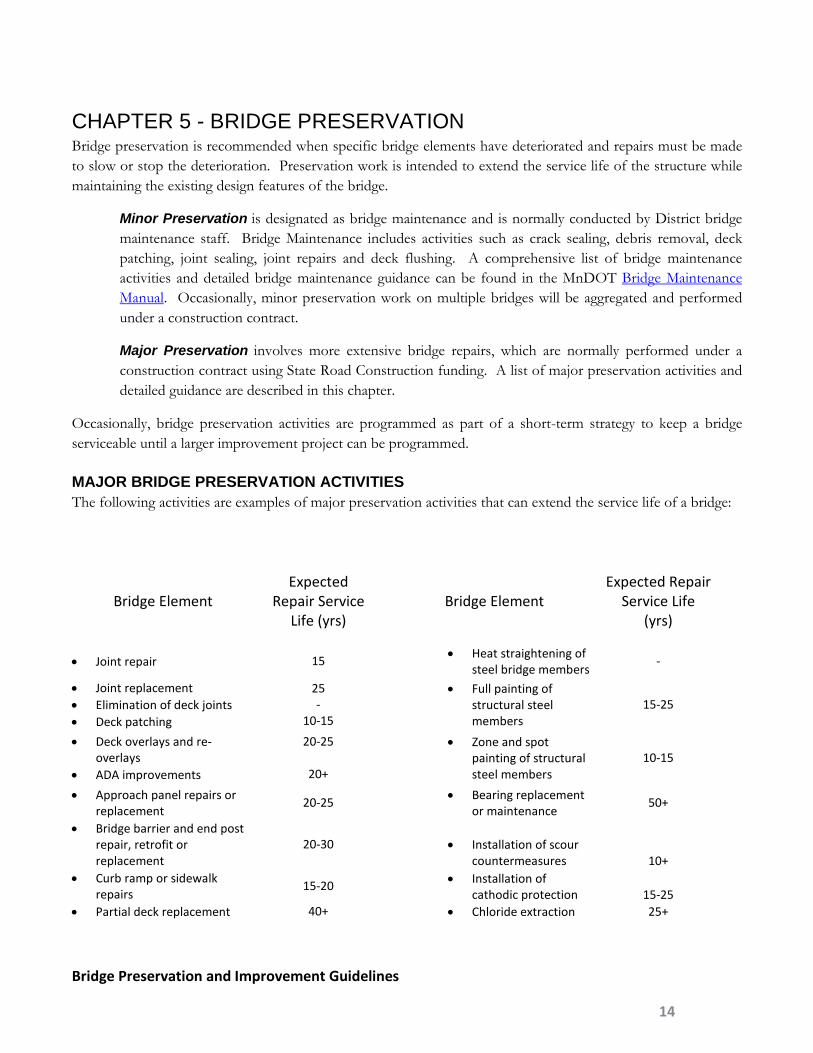
MAJOR BRIDGE PRESERVATION ACTIVITIES The following activities are examples of major preservation activities that can extend the service life of a bridge:
Bridge Element Expected
Repair Service Life (yrs)
Bridge Element Expected Repair
Service Life (yrs)
• Joint repair 15
• Heat straightening of steel bridge members
-
• Joint replacement • Elimination of deck joints • Deck patching
25 -
10-15
• Full painting of structural steel members
15-25
• Deck overlays and re-overlays
• ADA improvements
20-25
20+
• Zone and spot painting of structural steel members
10-15
• Approach panel repairs or replacement
20-25 • Bearing replacement
or maintenance 50+
• Bridge barrier and end post repair, retrofit or replacement
20-30
• Installation of scour countermeasures 10+
• Curb ramp or sidewalk repairs
15-20 • Installation of
cathodic protection 15-25 • Partial deck replacement 40+
• Chloride extraction 25+
Bridge Preservation and Improvement Guidelines
14

CONDITION CRITERIA Newer bridges generally require only preventive maintenance for the first 20-30 years of their service life. Major bridge preservation activities may become needed when a bridge is still in Good or Satisfactory condition (NBI≥6), but some bridge elements have deteriorated to a point where more significant repairs or a proactive preservation effort is necessary.
The following element conditions are basic guidelines for selecting appropriate preservation activities. Field conditions may warrant major preservation projects at other levels of deterioration.
Steel elements More than 15% in Condition State 3 or 4 Steel protective coatings More than 20% in Condition State 3 or 4 Reinforced concrete elements
More than 10% in Condition State 3 or 4
Prestressed concrete elements
More than 10% in Condition State 3 or 4
Timber elements More than 10% in Condition State 3 or 4 Concrete deck or slab elements
More than 15% in Condition State 3 or 4
Wearing surface elements More than 15% in Condition State 3 or 4 Joint elements More than 10% in Condition State 3 or 4 Bearing elements More than 10% in Condition State 3 or 4
COST CRITERIA A project meets the cost criteria for major preservation if the total cost of preservation work is less than 30% of the cost of a new bridge. If the total cost of preservation work is greater than 30% of the cost of a new bridge, consideration should be given to re-scoping the project as bridge rehabilitation to improve the bridge condition to the minimum criteria established in this document.
If the final decision is to proceed with a major preservation bridge project, the Design Memorandum prepared by the District PM should reference information on the type of bridge improvements considered, the cost of such improvements, and other pertinent information supporting that decision.
GENERAL GUIDELINES Bridge major preservation projects must meet the following requirements unless a Design Exception is approved;
• Major preservation projects must comply with barrier requirements as described Chapter 9. • Preservation activities should not result in the imposition of a new permit load restriction or a more
restrictive permit load restriction. An exception could be for short term overlays due to expected limited service life of the bridge.
• Structural elements in condition state 4 should be addressed in the project either with strengthening or arresting deterioration.
Bridge Preservation and Improvement Guidelines
15

Typically the Regional Bridge Construction Engineer and District Bridge Engineer will make a field visit to the bridge site with the Bridge Safety Inspection Reports, Structure Inventory Reports and Field Condition Assessment Form (near the end of this document) to identify potential repairs. In conjunction with the District, a bridge major preservation repair recommendation form will be prepared by the Bridge Office to help aid in the final plan development and cost estimates. For repair work that includes any steel painting the Bridge Office will also prepare Bridge Painting Recommendations. For reference, sample bridge repair recommendation forms are included near the end of this document. No formal written recommendation from the Bridge office is required for end post, approach guardrail, and approach panel reconstruction. Approach guardrail and approach panel work is prepared in the District grading plan.
STEEL PAINTING Consideration should be given to a bridge’s long term future when considering a paint project prior to a programmed bridge improvement project. Sometimes the combined cost of painting and near future bridge rehabilitation will approach an investment level where bridge replacement should be considered. Zone or spot painting may be appropriate with preservation projects with a limited service life extension.
Steel painting does not permanently arrest corrosion especially on surfaces with pack rust. Zone painting typically includes all members 7’ on each side of any deck joints. Containment for painting is a large expense, so a full paint project may be economical. Coordinate with the Bridge Office Architectural Specialist for final paint color recommendations. For bridges over highways that may get salt spray on the steel members, include removal of chlorides from the pitted areas after blasting.
The District shall identify bridges with lead or PCB paint prior to preparing paint recommendations. The District is required to test paint chips samples. Contact the Office of Environmental Stewardship for assistance in sampling the existing bridge steel paint for lead and PCB content, containment requirements during paint removal operations and proper management of waste paint media. Special environmental requirements are included in the contracts for bridges that have lead or PCB paint. The use of non-lead paint systems in new bridges began around 1975. The use of non-lead paint systems for repainting existing bridges began around 1985. PCBs could be in paint systems applied prior to 1980.
Painting steel pile bent piers in water is best done by Bridge Maintenance staff due to fluctuating water elevations. See the Bridge Maintenance Manual for details on bridge maintenance painting.
Weathering steel or COR-TEN® steel (spec 3309) started being used about 1975. Weathering steel bridge fascia beams can be painted for aesthetic reasons. Rust staining is a common feature on substructures where the water drains off of unpainted weathering steel. Existing painted weathering steel bridges can be blasted to remove paint to allow an even patina to form. Pay special attention to the construction details for the bolts of weathering steel beams to verify the paint system can be permanently removed. Weathering steel near all deck joints should be painted for protection from chlorides and possible pitting.
KTA Tator has been hired by the Bridge Office to develop District maintenance and contractor paint recommendation guidance. Guidance will include steel locations, paint condition, expected service life, paint products and surface preparation recommendations. After the report is finalized, the recommendations and flow charts will be included in these guidelines and the Bridge Maintenance Manual.
Bridge Preservation and Improvement Guidelines
16

BRIDGE ELEMENT REQUIREMENTS Refer to chapter 8, 9 and 10 for specific guidance related to bridge element requirements like barriers, end posts and bridge decks.
Bridge Preservation and Improvement Guidelines
17

CHAPTER 6 - BRIDGE REHABILITATION Bridge rehabilitation is a set of activities that repairs the deficiencies found in a structure and improves the geometrics and/or load-carrying capacity to at least the minimum criteria set in these guidelines, but may not meet new construction standards.
The District shall decide whether to replace or rehabilitate a structure; however, if the work is extensive, cost studies can aid in the decision. The Bridge Office Regional Bridge Construction Engineer is available to assist District personnel in evaluating and conducting improvement studies. Factors other than those included in these guidelines may determine whether studies are necessary and decisions concerning the need for studies must be based on each individual situation.
Bridge rehabilitation is typically undertaken when parts of a structure are in poor condition, the geometrics or load capacity is insufficient, and the bridge can be improved at a reasonable cost. Rehabilitation should both increase the overall lifespan of a bridge and correct deficiencies so that the existing structure is reconstructed to meet all current design criteria for new construction or rehabilitation (see Bridge Rehabilitation Minimum Guidelines table at the end of this section). When the rehabilitation has been completed, the portions of the superstructure and/or substructure not repaired should be in satisfactory condition and expected to last as long as the rehabilitated portion.
BRIDGE REHABILITATION ACTIVITIES The following activities are examples of cost-effective rehabilitation activities that can extend the service life of a bridge:
Bridge Repair Activity Expected Repair Activity Service Life (Yrs)
● Barrier and end post repair 20-30
● Full deck replacement 50+
● Superstructure replacement 50+
● Bridge widening on in place substructures 50+
● Bridge widening with widened substructures 50+
● Bridge raising -
● Substructure replacement 75+
● Major structural repairs increasing capacity 20+
CONDITION CRITERIA AND MINIMUM DESIGN When determining whether or not to improve an existing bridge, the current geometrics of the structure, as well as the projected structural conditions must be considered. Specific features that must be considered include the vertical clearance, lateral under clearance, load capacity, permit load capacity, scour criticality, and the condition
Bridge Preservation and Improvement Guidelines
18

of the main structural elements. The criteria used may vary depending on the classification/type of highway and the ADT on the structure. The minimum criteria for the various features are shown in Bridge Rehabilitation Minimum Guidelines (Table 1) for different highway classifications. If a structure meets the criteria listed, further rehabilitation is optional, subject to the design exception requirements discussed in this section. If a structure does not meet the minimum criteria listed, it should be rehabilitated to meet or exceed the minimum or considered for more substantial Improvement work. The minimum criteria used for bridge conditions are based on element level inspection criteria.
The criteria used to select bridge rehabilitation projects include the condition, load capacity and geometrics of the structure. Specific criteria include:
• Poor deck condition (wearing surface element or concrete deck or slab element condition state at 3 or 4), or
• Geometrics or load capacity that can be increased by widening or other means at a reasonable cost, or
• Poor superstructure condition (20% or more of major superstructure elements are in the condition state 3 or 4), or
• Poor substructure condition (40% or more of major substructure elements are in condition state 3 or 4).
GEOMETRICS AND LOAD CAPACITY At the time the scope of work is determined, minimizing substandard geometrics, increasing load capacity, and eliminating deficient elements of the bridge should be considered. Widening of structures should be considered to provide lane widths of up to 12 ft. Consideration should also be given to adding shoulders, adding sidewalks, and extending acceleration/deceleration lanes. An increase of load capacity must be considered for bridges with permit load restrictions. For bridges that carry high overweight permit traffic, on interstate routes or Over Size Over Weight (OSOW) Superload Corridors, the bridge rehabilitation must result in a structure that has no restrictions for adjacent traffic or speed (rated as 1) for standard permit classes A, B and C and inventory LRFR rating factor for HL-93 ≥ 0.9. For all other routes, the load rating must have an inventory LRFR rating factor for HL-93 ≥ 0.9 (See Chapter 8 for more information regarding rating factors.)
For bridges that carry traffic over an Over Size Over Weight (OSOW) Superload Corridor, the District should coordinate with the Office of Freight and Commercial Vehicle Operations to explore additional vertical and lateral clearances. Increasing the vertical clearance to 17 feet reduces the bridge hit risk and allows less restrictive permitting routes. Minimum requirements are defined as 16’-6” per the Bridge Rehabilitation Minimum Guideline (Table 1).
For projects whose primary purpose is to improve traffic capacity (additional traffic lanes, including turn lanes), the Districts are encouraged to meet current standard roadway width requirements.
In bridge situations not identified in the Bridge Rehabilitation Minimum Guideline (Table 1), use the National Bridge Inspection Recording and Coding Guide for the Structure Inventory and Appraisal of the Nation’s Bridges as a guide with a minimum NBI of 5.
Bridge Preservation and Improvement Guidelines
19

CONDITION AND COST CRITERIA Basic considerations for bridge rehabilitation projects are:
1) Repairs to the existing structure will require an expenditure of 30% - 70% of the cost of a new structure including approach costs; or
2) Load capacity has decreased due to deterioration or damage requiring strengthening of members; or
3) Geometric improvements are needed to match the approach roadway width or reduce accidents.
If any of these basic considerations is met, the bridge rehabilitation criteria should be applied to the project. Bridge rehabilitation projects should increase structure condition and features to the Bridge Rehabilitation Minimum Guidelines (Table 1) at the end of this section, but they do not necessarily have to meet current standards for new bridges. Current standards should be achieved in any case where feasible and prudent, especially where cost of bridge rehabilitation approaches 70% of the cost of a new bridge.
If the total cost of a bridge rehabilitation exceeds 70% of the cost of a new bridge, replacement should be considered to bring the crossing up to current design standards. When deciding to do a bridge rehabilitation that is in excess of 70% of the cost of a new bridge, the Design Memorandum should reference information on the type and cost of options considered including approach costs.
GENERAL GUIDELINES The Regional Bridge Construction Engineer will typically make a field visit to the bridge site with the Bridge Safety Inspection Reports, Structure Inventory Reports and Field Condition Assessment Form (example form near the end of document) to identify potential repairs. In conjunction with the District, a Bridge Rehabilitation Recommendation form will be prepared by the Bridge Office to help aid in the final plan development and cost estimates. For repair work that includes any steel painting, the Bridge Office will also prepare Bridge Painting Recommendation. For reference, sample bridge recommendation forms are included near the end of this document. For extensive bridge rehabilitation projects involving substructure widening, the Bridge Office will prepare preliminary bridge plans for District approval.
Bridge rehabilitation projects for structures that are less than 500 feet in length should be programmed to meet the minimum requirements listed in the Bridge Rehabilitation Minimum Guidelines. If additional beams and substructures are required to meet the minimum roadway width, the Districts are encouraged to program for additional widening to meet current width standards. Also, when vehicles must substantially reduce speed due to a narrow bridge width in comparison to the approach roadway or substandard horizontal or vertical bridge alignment, the bridge should be programmed to current width standards.
EXCLUSION FROM THE BRIDGE REHABILITATION MINIMUM GUIDELINES The minimum deck width values shown in the Bridge Rehabilitation Minimum Guidelines (Table 1) are 4 to 6 feet wider than the minimum widths required to remove a structure from the FHWA list of functionally obsolete bridges. For the purposes of these guidelines, the 500 foot limit extends the use of wider and safer shoulder width to most overpass bridges and stream crossings. For major structures or bridges over 500 feet in length, particularly where additional beams and substructures are required to meet the wider shoulder width, the costs and benefits of wider shoulders should receive more careful consideration. Bridge rehabilitation on structures
Bridge Preservation and Improvement Guidelines
20

longer than 500 feet that don’t meet the minimum deck width requirements will require approval of a Design Exception.
GUIDELINES FOR BRIDGE DECKS Deck replacement projects, due to their cost, should be considered carefully to ensure that completed structures do not result in the continuation of substandard conditions (below current MnDOT new construction standards) that will need to be addressed during the extended life of the new deck. Decks should be constructed in accordance with current standards as described in Chapter 9 and 10 unless an approved design exception has been obtained.
Preparation of Project Memorandums and studies that involve bridge deck reconstruction should include a thorough documentation of future construction plans in the vicinity of the bridge. The report should also discuss any remaining deficiencies in load, safety, or geometrics, such as protective guardrail, bridge width, vertical, or horizontal alignment, and pedestrian needs.
BRIDGE ORNAMENTAL TRAFFIC BARRIER AND CURBS For bridges with posted speed limits over 35 mph, all fully ornamental traffic railings should be replaced or have other intermediate traffic barriers meeting current standards placed between pedestrian and vehicle traffic. See bridge barrier requirements in Chapter 9 for details. For new or redecking bridges carrying NHS routes, FHWA requires approved crash tested barriers.
DESIGN EXCEPTIONS A design exception must be submitted by the District and approved by the State Bridge Engineer for bridge rehabilitation projects that do not meet Bridge Rehabilitation Minimum Guidelines (Table 1). In rare situations, a major preservation project will require a Design Exception that does not meet Chapter 6 requirements.
The values given in the Bridge Rehabilitation Minimum Guidelines (Table 1) will result in Federal appraisal ratings that are not functionally obsolete (NBI Appraisal rating 5 or higher).
(See http://dotapp7.dot.state.mn.us/edms/download?docId=617904 for the design exception worksheet and submittal format.) Refer to Section 2-6 of the MnDOT Road Design Manual for guidance on geometric design exceptions. The Design Exception form is attached near the end of this document.
To be eligible for federal funding, a bridge rehabilitation project should meet the construction standards for a new bridge. Federally funded projects may require higher minimum standards than would be required for state funded rehabilitation projects for the following features:
• Bridge roadway width • Bridge structural capacity • Bridge lane width • Vertical clearance
Bridge Preservation and Improvement Guidelines
21

Approval of design exceptions for federally funded bridge rehabilitation projects that meet the bridge Rehabilitation Minimum Guidelines (Table 1) requirements, but not new standards, should be routine as long as highway safety is maintained or improved, and the bridge does not have an accident history that relates directly to the critical design element.
Design exceptions are usually submitted with the Design Memorandum or other environmental documents by the District.
The RDM and MnDOT LRFD BDM standards may be superseded by the Tech Memo 12-12-T5-06 Shoulder Width Standards for State Highways and Tech Memo 12-14-B-03 Bridge Width Standards for State Highways. The design exception form attached at the end of this document will need to updated to reflect changes to this document.
Items requiring design exceptions should be noted with supporting rationale in the bridge rehabilitation recommendations issued by the Bridge Office. If the design exception is recommended for approval by the State Bridge Engineer, the Regional Bridge Construction Engineer from the Bridge Office will substantially complete the request for the design exception for District approval.
The District in conjunction with the Bridge Office must complete the design exception form and address any relevant accident history on the bridge and other bridge related safety concerns before submitting it to the State Design Engineer for approval. More information regarding the design exception process can be found on the MnDOT Office of Technical Support website at: http://dotapp7.dot.state.mn.us/edms/download?docId=623068
BRIDGE ELEMENT REQUIREMENTS Refer to chapter 8, 9 and 10 for specific guidance related to bridge element requirements like barriers, end posts and bridge decks.
Bridge Preservation and Improvement Guidelines
22
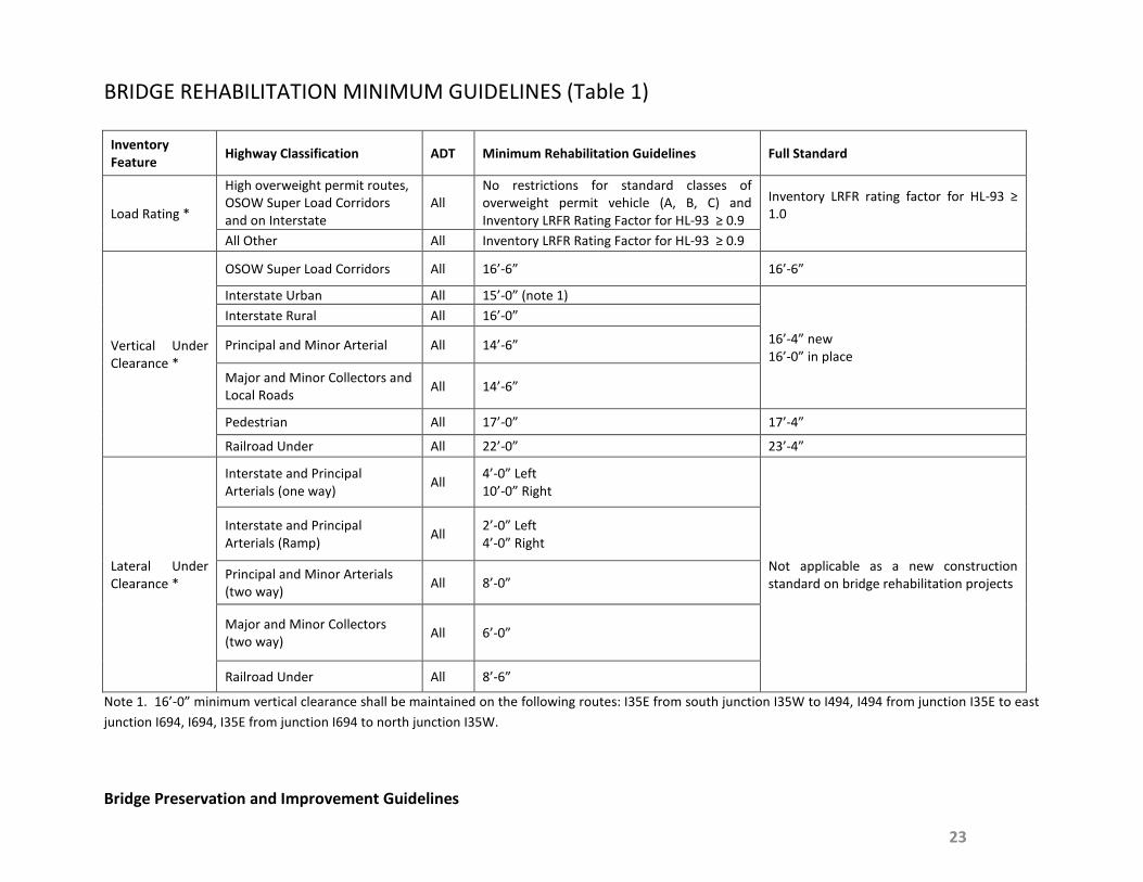
BRIDGE REHABILITATION MINIMUM GUIDELINES (Table 1)
Inventory Feature Highway Classification ADT Minimum Rehabilitation Guidelines Full Standard
Load Rating *
High overweight permit routes, OSOW Super Load Corridors and on Interstate
All No restrictions for standard classes of overweight permit vehicle (A, B, C) and Inventory LRFR Rating Factor for HL-93 ≥ 0.9
Inventory LRFR rating factor for HL-93 ≥ 1.0
All Other All Inventory LRFR Rating Factor for HL-93 ≥ 0.9
Vertical Under Clearance *
OSOW Super Load Corridors All 16’-6” 16’-6”
Interstate Urban All 15’-0” (note 1)
16’-4” new 16’-0” in place
Interstate Rural All 16’-0”
Principal and Minor Arterial All 14’-6”
Major and Minor Collectors and Local Roads All 14’-6”
Pedestrian All 17’-0” 17’-4”
Railroad Under All 22’-0” 23’-4”
Lateral Under Clearance *
Interstate and Principal Arterials (one way) All 4’-0” Left
10’-0” Right
Not applicable as a new construction standard on bridge rehabilitation projects
Interstate and Principal Arterials (Ramp) All 2’-0” Left
4’-0” Right
Principal and Minor Arterials (two way) All 8’-0”
Major and Minor Collectors (two way) All 6’-0”
Railroad Under All 8’-6”
Note 1. 16’-0” minimum vertical clearance shall be maintained on the following routes: I35E from south junction I35W to I494, I494 from junction I35E to east junction I694, I694, I35E from junction I694 to north junction I35W.
Bridge Preservation and Improvement Guidelines
23
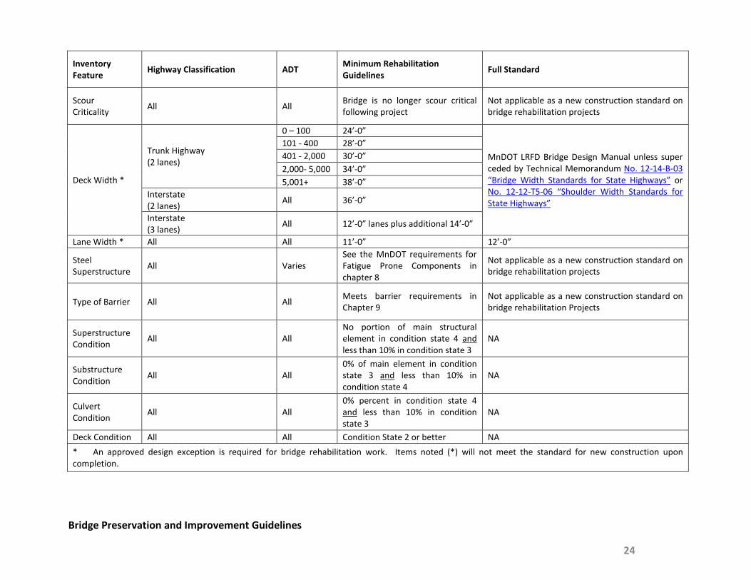
Inventory Feature Highway Classification ADT Minimum Rehabilitation
Guidelines Full Standard
Scour Criticality All All Bridge is no longer scour critical
following project Not applicable as a new construction standard on bridge rehabilitation projects
Deck Width *
Trunk Highway (2 lanes)
0 – 100 24’-0”
MnDOT LRFD Bridge Design Manual unless super ceded by Technical Memorandum No. 12-14-B-03 “Bridge Width Standards for State Highways” or No. 12-12-T5-06 “Shoulder Width Standards for State Highways”
101 - 400 28’-0” 401 - 2,000 30’-0” 2,000- 5,000 34’-0” 5,001+ 38’-0”
Interstate (2 lanes) All 36’-0”
Interstate (3 lanes) All 12’-0” lanes plus additional 14’-0”
Lane Width * All All 11’-0” 12’-0”
Steel Superstructure All Varies
See the MnDOT requirements for Fatigue Prone Components in chapter 8
Not applicable as a new construction standard on bridge rehabilitation projects
Type of Barrier All All Meets barrier requirements in Chapter 9
Not applicable as a new construction standard on bridge rehabilitation Projects
Superstructure Condition All All
No portion of main structural element in condition state 4 and less than 10% in condition state 3
NA
Substructure Condition All All
0% of main element in condition state 3 and less than 10% in condition state 4
NA
Culvert Condition All All
0% percent in condition state 4 and less than 10% in condition state 3
NA
Deck Condition All All Condition State 2 or better NA * An approved design exception is required for bridge rehabilitation work. Items noted (*) will not meet the standard for new construction upon completion.
Bridge Preservation and Improvement Guidelines
24

CHAPTER 7 - BRIDGE REPLACEMENT Bridge replacement is the removal of the in place structure and replacement with a new bridge meeting all current design and construction standards.
CONDITION AND COST CRITERIA Candidates for bridge replacement are generally in structurally deficient or functionally obsolete status and identified based on the BPI rating in BRIM. These bridges have reached a point in their service life where extensive rehabilitation work would be necessary to restore the transportation function of the bridge.
The general criteria for developing a list of potential replacement candidates include condition, cost, age, and geometrics. The specific criteria include:
1. The bridge requires excessive repair by MnDOT maintenance staff to remain in service, and:
a. one or more main structural elements are in poor condition (20% or more in condition states 3 or 4); and
b. the cost to rehabilitate the bridge is 70% or more of the replacement cost; or
c. the bridge is nearing the 70-year average life of a structure.
2. The bridge is structurally deficient and cannot be strengthened to remove the restriction at a reasonable cost.
3. Horizontal or vertical clearances are substandard and have caused accidents and pose a potential safety problem.
4. Roadway realignment requires a new location for the structure.
When a structure is replaced, it shall be designed to meet the criteria for new bridges set forth in the MnDOT LRFD Bridge Design Manual.
GENERAL GUIDANCE The District in coordination with the Regional Bridge Construction Engineer will identify replacement candidates to be put into the STIP. Generally the BPI rating for replacement candidates based on condition are in the top 20% for the District.
Bridge Preservation and Improvement Guidelines
25

CHAPTER 8 - BRIDGE ELEMENTS This chapter describes various requirements for the bridge recommendation process.
BARRIER AND END POSTS The barrier requirement in Chapter 9 establishes the design requirements for bridge barrier and end posts for almost all major preservation and improvement projects. It should be referenced when establishing work scopes and recommendations for major preservation and improvement projects.
Providing a bridge barrier meeting current standards should be considered for any bridge preservation or improvement project where existing conditions present an elevated risk to the traveling public or structural function of the bridge.
End posts and guardrail transitions shall be evaluated and improved in accordance with Bridge Barrier and Endpost Chapter 9 on almost all bridge major preservation and improvement projects, as well as roadway projects that replace guardrail at the ends of the bridge. See Chapter 9 for major preservation projects that do not require barrier and endpost safety upgrades.
BRIDGE DECKS AND DECK PROTECTIVE SYSTEMS Appropriate investments in bridge deck preservation and rehabilitation can significantly minimize life cycle costs and slow or prevent the deterioration of bridge superstructure and substructure elements.
A systematic approach to managing bridge decks includes preventive maintenance (crack and joint sealing), major preservation efforts (overlays and re-overlays) and eventual rehabilitation (full deck replacement). The Bridge Deck Guidance in Chapter 10 contains suggested repair strategies based on bridge deck age, traffic and condition. Additional guidance on deck management is provided in the Bridge Maintenance Manual.
PIER PROTECTION The MnDOT LRFD Bridge Design Manual (BDM), Article 11.2.3, contains detailed guidance on evaluating the need for pier protection. It should be referenced when establishing work scopes and recommendations for bridge rehabilitation projects.
The BDM pier protection provisions for new bridges shall apply (including exemptions for design speed and ADTT) to any bridge rehabilitation project when:
• Scope of bridge work includes the widening of substructures.
Consideration should be given to meeting the BDM pier protection provisions for new bridges on bridge major preservation and rehabilitation projects that meet any of the following criteria:
• Roadway below bridge has speed limit > 40 MPH
• Roadway below bridge has ADTT > 1,200
• Roadway below bridge has curved alignment
• Piers have fewer than 3 columns and the superstructure is non-continuous
Bridge Preservation and Improvement Guidelines
26

• Roadway below bridge has high accident history
The BDM pier protection provisions for new bridges shall apply (including exemptions for design speed and ADTT) to roadway reconstruction projects that meet either of the following criteria:
• Roadway reconstruction moves the edge of travel lane to within 30 feet of a pier.
District roadway designers should consider meeting current pier protection standards for roadway projects meeting the following criteria:
• New guardrail connections to the pier are installed. • Profile grade raise reduces the effective height of existing pier protection. • Extensive work is being performed on the roadway corridor and the pier does not have an existing crash
strut.
The BDM and AREMA pier protection provisions for new bridges over railroad traffic shall apply to any bridge widening that includes substructures or redecking projects when the substructure is within 25’ of center of railroad track and meet any of the following criteria:
• Roadway carries interstate traffic. • Roadway carries ADT > 40,000. • If the bridge has 2 column pier and non-continuous superstructures.
Consideration should be given to meeting the BDM and AREMA pier protection provisions for new bridges on bridge major preservation and rehabilitation projects with a substructure within 25’ of center of the railroad track and meet any of the following criteria:
• If the bridge has 2 column pier and continuous superstructures. • Increased railroad derailment risk like high railroad traffic, high speeds, or on mild horizontal curve. • There is no existing railroad pier protection strut.
Note that when a crash strut is the proposed solution to meet the pier protection requirements, the ability of the existing foundation to carry the additional weight of the crash strut must be considered.
LIMITS OF CONCRETE REMOVAL Major preservation or rehabilitation can require the removal of significant areas of unsound deck, superstructure or substructure concrete. These removals may result in a temporary situation in which the structural integrity of the bridge is compromised and load-carrying capacity is reduce, and thus must be designed and constructed with appropriate considerations.
Bridges with concrete deck, superstructure, or substructure elements in Condition State 3 or 4 should be assessed for the possibility of extensive removals. This assessment may include additional evaluation through sounding, coring or sample removals conducted by the District.
Areas of particular concern include;
Bridge Preservation and Improvement Guidelines
27

• pier caps • non-redundant pier columns • concrete box girder hinges • beam ends and diaphragms • areas under bearings • bridge decks over traffic • potential unstable beams such as curved steel beams • large areas of deck removal • deteriorated barriers • staged bridges still carrying adjacent traffic
If it is anticipated that significant concrete removal will be required, shoring should be recommended for the project and the contractor will be responsible for the necessary engineering, shoring plans, and removal sequences. Depending on the deterioration extent, the District may have to quantify the unstable areas and provide sketches to help designers understand potential construction removal risks.
LOAD FACTOR RATINGS (LFR) AND LOAD AND RESISTANCE FACTOR RATINGS (LRFR) Eventually all bridges will be rated using LRFR and overweight truck permits will be analyzed based on LRFR. To help in that transition for existing bridges not yet rated using LRFR, they may be reanalyzed as part of a repair project. For most bridges built before the mid-1990s, repair projects were designed in accordance with the AASHTO Standard Specifications for Highway Bridges. However, the AASHTO Standard Specifications for Highway Bridges is no longer being maintained, has not been updated since 2002, and has several documented deficiencies. Thus it is appropriate for most repair projects to be evaluated and designed using the current edition of the AASHTO LRFD Bridge Design Specifications (LFRD) along with the latest load and resistance factor rating (LRFR) requirements from the Manual for Bridge Evaluation (MBE). See the MnDOT LRFD Bridge Design Manual section 4.6.2 for repair project specific design requirements. Bridge preservation projects that significantly increase the dead load, like railing modifications, or net increases in wearing course thickness, shall be analyzed using LRFR. Other preservation projects like painting, scour mitigation and deck repairs do not require any analysis to be completed as part of the development of the final plan. Ideally, these projects may include an LRFR rating at the scoping phase of the project to assess potential areas of concern that may need incorporation into the upcoming repair plan or future projects. For bridge rehabilitation projects, such as deck replacements, superstructure replacements, or deck widenings, the design and ratings for these types of projects shall be completed using LRFD and LRFR procedures. Because these types of projects are a major investment, it is important to evaluate the bridge using current standards. Ideally these evaluations should be performed during the scoping phase of the project to help identify scope and cost increase requirements. As noted in Chapter 6, an LRFR inventory rating factor of 0.9 would be the minimum acceptable level for bridge rehabilitation projects without a Design Exception. This reduced
Bridge Preservation and Improvement Guidelines
28

inventory rating factor is considered acceptable recognizing that some of the service life of the bridge has transpired.
The consequence of reanalysis using a different design code may identify additional needs and require the scope and cost of repair projects to increase if the LRFR results in inadequate rating factors. It is important to identify and estimate the costs as early as possible in the project development stage so that District programs can accommodate any changes. Bridge elements of particular interest are concrete pier caps, continuous steel beams and prestressed concrete beam shear. By strengthening inadequate existing bridges in upcoming projects, the eventual transition to LRFR permitting will be easier and provide consistency for the processing for overweight trucks.
In addition, the District should document as part of their safety inspections any substantial deterioration or damage that would indicate inadequate original design to the Bridge Office for inclusion in the repair project. A new load rating of certain elements may be identified in any repair project that will be analyzed in final design and may increase the scope of repair project.
PRESTRESSED BEAM CONCRETE SHEAR Prestressed beam shear analysis has changed from earlier AASHTO design codes. Many early prestressed beam designs from the 1970s and 1980s do not meet current LRFD requirements. As part of a major preservation or rehabilitation project when adding additional dead load, the shear capacity needs to be evaluated and considered for strengthening if needed. For bridges with no additional dead load added as part of project, the prestressed beams should be thoroughly inspected by the District staff for any shear cracking and possible inclusion within the repair project. Increased concrete beam strength from the plan, FRP strengthening and possible new research findings may be used to increase the load capacity and meet the minimum requirements for either a major preservation or rehabilitation project.
RETROFIT OR REPLACEMENT OF FATIGUE PRONE COMPONENTS NON-REDUNDANT MEMBERS This requirement applies only when all of the following listed conditions apply:
(1) The member is structural steel and is a primary load-carrying member. (2) The member is composed of welded plates or has welded attachments, categorized as fatigue category D,
E, or E’ according to the AASHTO LRFD Bridge Design Specifications, or has welded attachments for floor beams or diaphragms which are not securely attached to both flanges.
(3) Heavy commercial average daily traffic (HCADT) is greater than or equal to 200 or fatigue cracking is present in structural welds. HCADT may be computed as 10% of ADT where heavy commercial volumes are not well recorded.
(4) Planned scope of work is classified as “rehabilitation” as defined in current Bridge Preservation and Improvement Guidelines.
Retrofitting in negative moment areas (Area “A”) or replacements of non-redundant members shall be provided in bridge rehabilitation projects for members meeting the above criteria.
REDUNDANT MEMBERS
Bridge Preservation and Improvement Guidelines
29
Retrofitting or replacing redundant members is not required except when a fatigue-life analysis shows that the remaining life is significantly less than the expected remaining service life of the bridge. If the remaining life is less than expected service life, the requirement for retrofitting or replacing non-redundant members shall apply.
FRACTURE CRITICAL BRIDGES AASHTO specifications define Fracture Critical Members (FCM) as tension members or tension components of members whose failure would be expected to result in collapse of the bridge. FCM are in tension and will not have another member which will serve the function of the failed member. If a member has an alternative system to redistribute the load, that member has redundancy. More frequent safety inspections are required for bridges with fracture critical members.
The Districts should proactively prevent damage of FCM with bridge maintenance and repair projects to reduce the risk of catastrophic failure. Strengthening or adding redundancy of the FCM should be considered in rehabilitation projects even if those members do not control the load rating.
ASBESTOS AND REGULATED WASTE ASSESSMENT The District is required to provide an Asbestos and Regulated Waste Assessment for any project that includes bridge removal activities. All bridge rehabilitation and replacement projects will normally require this assessment. Districts should request an assessment from the Office of Environmental Stewardship about 2 years prior to letting so that the contract plans can be prepared to meet all environmental requirements.
These assessments are typically not required for bridge major preservation projects, except when barriers, sidewalks, cork joints or waterproofing is removed. Past assessments have shown that asbestos containing materials are not typically found in elements affected by mill and overlays, expansion joint replacements, or painting projects.
Culvert repairs or replacements do not need an Asbestos and Regulated Waste Assessment report.
HISTORIC BRIDGES Bridges that are on or eligible for the National Register of Historic Places are often candidates for major preservation and improvement. These bridges represent the Department’s engineering and transportation heritage and their preservation is important. Historic bridge projects are required to follow Section 106 of the National Historic Preservation Act of 1966, which may have a significant impact on project development process and decision making during the planning of bridge projects.
From a historic preservation standpoint, it is desirable to allow a historic bridge to remain in service if the bridge has a satisfactory performance history and a reasonable level of repair can be done to extend its service life. From an asset management standpoint, it is important to ensure that bridge investments serve transportation needs, ensure structurally sound structure, provide an acceptable level of traffic safety and minimize life-cycle costs.
The principles and guidance established in this document serve as the general basis for planning and programing all bridge preservation and improvement projects, including historic bridges. However, each historic bridge is unique and project-specific purpose and needs should be accommodated in coordination MnDOT Cultural Resources Unit, which will consult with SHPO. Bridge Preservation and Improvement Guidelines
30

TYPE W BRIDGE CULVERTS Box culverts designated in the bridge inventory with the prefix “W” (i.e.W10x10) were designed according to standard plan sheets that were developed from 1928 through 1939. The culverts were designed with a single layer of reinforcement the slabs and walls with no effective moment reinforcement through the corners. The Type W culvert standards were replaced beginning in 1940 by Type C standards which, like current standards, include a top and bottom layer of reinforcement in each slab and wall and moment reinforcement through the corners. It is unclear as to what standard was used prior to 1928.
Since Type W culverts are already 75 or more years old, analysis is necessary before making recommendations to repair or extend them. A new calculated load rating (i.e. not from the table provided in the Culvert Rating Form) should be determined for the current fill height. Use a 3000 psi concrete strength and 30,000 psi yield for reinforcement. The 10 foot culverts were designed for fills from 0’-10’, 10’ – 20’, and 20’-35’. The 12 foot culverts started at 0’-8’ fills. Since original plans or design data may not have been preserved for many of these culverts, when referencing the design standards, designers should assume that fill has increased over time (2 feet minimum). For example, if the inventory indicates 11 feet of fill over a Type W culvert, unless more information is available the 0-10' standard should be assumed.
Type W culverts with newly calculated operating ratings less than HL-93 rating factor less than 1.25 should not be extended. Bridge maintenance could be performed to prevent collapse.
Repairs or modifications to Type W culverts with newly calculated operating ratings greater than an HL-93 rating factor greater than 1.25 should be scoped to raise the NBI condition evaluation for the culvert to at least 6 (satisfactory).
In special situations, the District may choose to extend a W culvert for shoulder widening if the structure is in good condition, the consequences to replacement have large negative impacts to the project, and the culvert has adequate hydraulic capacity.
PEDESTRIAN ACCOMMODATIONS PER THE AMERICANS WITH DISABILITIES ACT (ADA) The current threshold for providing accessibility improvements on bridges is bridge improvement projects which occur on 50 to 100 year cycle. Under the current MnDOT transition plan MnDOT has set the goal for substantially completing its transition plan in 20 years. To ensure that goal is accomplished MnDOT should routinely consider providing accessibility improvements as a part of bridge preservation projects which occur more frequently. A formal design exception will not be required if accessibility improvements are not made, however, coordination between the District and the ADA Program Engineer should occur before the project scope is finalized.
BRIDGE MAJOR PRESERVATION PROJECTS Major bridge preservation projects that include joint replacements, joint eliminations, or approach panel replacements in the project scope must include curb ramp modifications if any of those bridge features are within proximity of a curb ramp and could ultimately limit the required pedestrian accommodations. Those required pedestrian accommodations include curb ramps, landings, secondary ramps, Accessible Pedestrian Signal “ready” construction and relocating physical barriers that obstruct or otherwise interfere with the
Bridge Preservation and Improvement Guidelines
31
Pedestrian Access Route. If the bottom of a pedestrian ramp is within 25’ of the proposed joint or approach panel work (or longer if the bridge has a steep profile), more investigation should be performed to verify potential impacts to ADA governed facilities.
Strong consideration should be made to also include curb ramp upgrades as described in the above paragraph if a bridge project contains a deck rehab or overlay. Federal Accessibility requirements state roadway pavement overlays, mill and overlays, and concrete pavement rehabs trigger the curb ramp replacement threshold. Those same Federal requirements do not differentiate between a roadway surface and a bridge deck surface. While not specifically stated, the intent to upgrade curb ramps on bridge deck overlays is present.
All sidewalks and shared use paths on bridges and approach panels should not have vertical deviations greater than ¼” since they create a trip hazard. These vertical deviations often occur at surface utilities, joints, and other areas that may have settled or shifted. When deck repairs, approach panel repairs, bridge barrier repairs, bridge barrier replacements, deck patching, or similar work is performed, the sidewalks/paths must be evaluated and any vertical discontinuities repaired as feasible. Crack sealing of decks and similar activities should also be performed on any pedestrian facilities.
Major bridge preservation projects that include ADA improvements will ensure newly constructed bridge elements won’t need to be reworked in a future pedestrian accessibility project. Additionally, efficiencies will be gained since the specialty bridge repair contractor is already mobilized and pedestrian and vehicular traffic impacts will be consolidated.
BRIDGE IMPROVEMENT PROJECTS Pedestrian needs and existing surrounding facilities shall be evaluated for scoping purposes on all bridge improvement projects. Those pedestrian needs should be incorporated and they must include the appropriate accessibility accommodations. The proposed bridge cross section should provide a multi modal balance between lane, shoulder, trail, and sidewalk width requirements. Sidewalk standard widths should be met if feasible.
On bridge deck replacement projects all pedestrian ramps at an intersection should be upgraded if the vertical tie down falls anywhere in that intersection or if the horizontal geometrics of the intersection are altered. Designing and constructing the adjacent intersection as a single unit helps ensure a coordinated long term pedestrian product is achieved.
OTHER REQUIREMENTS The District will reference MnDOT Technical Memorandum No. 15-02-TR-01 for ADA standards as well as additional ADA pavement thresholds for curb ramp upgrades that could be triggered if associated pavement work is performed beyond the bridge limits.
Bridge Preservation and Improvement Guidelines
32

CHAPTER 9 - BRIDGE BARRIER AND ENDPOST This requirement applies to all Major Preservation and Improvement bridge projects. This requirement is in substantial compliance with the 1993 FHWA Policy Memo regarding the use of crash-tested barrier based on NCHRP Report 350, Recommended Procedures for the Safety Performance Evaluation of Highway Features. Updated FHWA policy, now defines crashworthy devices as those that have passed a crash test conducted under the procedures defined in NCHRP Report 350 or the AASHTO Manual for Assessing Safety Hardware (MASH).
Crash test information for various bridge barrier designs can be found in Table C.2.1 of the MnDOT Bridge Inspection Manual. A copy of the manual can be found on the MnDOT Bridge Office website at: http://www.dot.state.mn.us/bridge/manuals/index.html
Any bridge with a barrier modification should be analyzed for changes in dead load and impacts to the bridge load rating.
NEW BARRIERS Crash-tested bridge barriers meeting NCHRP Report 350 or MASH shall be provided on new bridges, newly widened sections of bridge deck, full deck replacements and barrier replacement projects. Design shall be in accordance with the MnDOT LRFD Bridge Design Manual.
IN-PLACE BARRIERS When any major preservation or improvement work is scheduled for a bridge with a barrier not meeting a 10-kip design load requirement established in the AASHTO Standard Specification (1964 edition and later), the barrier shall be modified or replaced with barriers meeting the crash-tested shape and strength requirements for new bridges.
When major preservation bridge work is scheduled for bridges with barriers meeting the AASHTO 10-kip design load requirement, the existing bridge barrier can generally remain in place. However, the barrier should be replaced or modified when the following conditions exist;
• In-place barrier is in poor structural condition (all design speeds) • In-place barrier poses an elevated risk:
o potential snagging condition o curb projection greater than 9 inches
• In-place conditions indicate an elevated risk: o history of barrier impacts o site-specific roadway geometrics o critical superstructure members are susceptible to impact
The following work is exempt from this provision:
• complex bridges (such as through-trusses) that would require extensive reconstruction or significant reduction in roadway width or load carrying capacity to meet this criteria
• bridge maintenance work
Bridge Preservation and Improvement Guidelines
33

• major preservation work with no deck repairs
END POSTS With any barrier upgrade, the end post and the approach guardrail transition will be upgraded as necessary to meet NCHRP Report 350 or AASHTO MASH requirements. This requirement applies to all 4 corners of the bridge if there is a potential for temporary or permanent two-way traffic on the bridge in the future.
The guardrail connection shall include integral end posts or separate end posts that are rigidly connected to the bridge (not free standing)*.
When the project involves approach guardrail upgrades and no bridge work, the end post and the approach guardrail transition will be upgraded as necessary to meet NCHRP Report 350 or AASHTO MASH requirements. This requirement applies to all 4 corners of the bridge if there is a potential for temporary or permanent two-way traffic on the bridge in the future and the in place rail meets NCHRP 350 or AASHTO MASH.
Existing end posts must meet all of the following requirements to be considered acceptable:
• Minimum length (at the top) = 2'-8" • Minimum thickness (at the base) = 1'-6" • Minimum amount of vertical reinforcement in the front face = 3.16 square inches • Minimum height 2'-8", the leading edge height may be 2'-3" +/- and sloped upward to the 2'-8"
minimum height at the trailing edge • Must be rigidly connected to the bridge (not free standing)*
Standard Plan Sheets 5-297.609 and 5-297.619 shows the face of the new end post lining up with the front face of the existing bridge barrier. It also shows a maximum curb projection of 9 inches from the face of the barrier. If a proposed construction project does not include work to retrofit the bridge barriers, and the new end post won't line up with the bridge barrier face or the curb projection exceeds 9 inches, the new guardrail transition and end post may not meet the required geometric criteria. This issue needs to be resolved by the District. For such projects, it may be a good time to replace or retrofit the bridge barrier.
* End posts can be designed to be attached to the approach panel instead of rigidly connected to the structure. The District and Bridge Office final designer will need to coordinate plan details and payment.
Bridge Preservation and Improvement Guidelines
34

CHAPTER 10 – BRIDGE DECK GUIDANCE
GUIDELINES FOR BRIDGE MAINTENANCE Appropriate bridge maintenance can maximize the service life of in place bridge decks. The intent of this maintenance work is to slow deterioration and keep a deck in a serviceable condition until more extensive repairs or deck replacement is warranted. Guidelines for typical condition and repair strategy are included in the MnDOT Bridge Maintenance Manual.
Districts should pay particular attention to monitoring the condition of in-place concrete overlays and monolithic decks on box girder bridges and other structures for which deck replacement is cost prohibitive or presents significant constructability problems. Structures of this type should be monitored to determine the chloride content at various depths of the overlay at intervals not exceeding 5 years. As the chloride content at the base of the overlay begins to approach half the corrosion threshold, testing should be done more frequently. The bridge should be programmed for overlay replacement before the concrete at the level of the top rebar reaches half of the corrosion threshold. Half of the corrosion threshold is equal to approximately 0.075% water-soluble chloride ion or 750 ppm. For acid-soluble chloride ion, half the threshold is approximately 0.0175% or 175 ppm. The MnDOT Central Lab generally runs acid-soluble chloride ion tests. For information on chloride sampling methods, contact the Office of Materials and Road Research Concrete Unit.
GUIDELINES FOR BRIDGE DECK REPAIRS Priority guidelines for deck repair by contract are provided below. They are based on the premise that overlays are most economically justified when:
• Existing overlays have isolated delaminated areas that can be repaired with deck patches; or • Overlays or re-overlays are placed on basically intact decks as a protective measure; or • Deck replacements are deferred until full deck removal and replacement is warranted.
The following general categories and procedures have been established for protective overlay projects if the top rebar cover is 2” or more. The repair procedure could change based upon the condition of the underside of the deck.
Bridge Preservation and Improvement Guidelines
35

CONDITION CATEGORY
PERCENT OF UNSOUND DECK AREA
WORK TYPE OPTIONS Traffic Volume (current ADT)
< 2,000 2,000 to 10,000 > 10,000 and Interstates
I Slight Deterioration
0 to 2% SIMS deck condition state 2
Priority 11 Do Nothing or Spot Repairs
Priority 9 Do Nothing or Spot Repairs
Priority 8 Do Nothing or Spot Repairs
II Moderate Deterioration
2% to 10% SIMS deck condition state 3
Priority 10 Mill And Patch
Priority 7 Mill And Patch
Priority 6 Mill And Patch or Re-Overlay
III Severe Deterioration
10% to 25% SIMS deck condition state 4
Priority 5 Deck Repairs, 100% Scarify And Add Overlay
Priority 4 Deck Repairs, 100% Scarify And Add Overlay
Priority 3 Deck Repairs, 100% Scarify And Add Overlay
IV Critical Deterioration
> 25% SIMS deck condition state 5
Priority 4 *Deck Repairs, 100% Scarify And Add Overlay
Priority 2 **Schedule New Deck
Priority 1 **Schedule New Deck
* Priority 4 decks should be overlayed only if a thorough evaluation indicates that minimal unsound concrete extends below the top of rebars. If extensive areas of unsound concrete exist below the top of rebars, patch and repair and maintain the deck in accordance with the guidelines until the end of its useful life.
**When the useful service life of the deck has ended, a bituminous overlay may be required to maintain ride ability. A limited service concrete overlay may be economical to extend the useful life of the deck.
If top rebar cover is less than 2 inches:
For SIMS deck condition state 2 or 3, perform deck repairs and protective overlay. For SIMS deck condition state 4, provide limited service overlay and consider deck replacement. For SIMS deck condition state 5, schedule a new deck after usable life of in-place deck is expended. Monitor the underside of the deck over traffic to ensure concrete is sound.
These guidelines are modified for bridges where the deck is a portion of the main structural support member. (Some examples are concrete box-girder, concrete slab-span, and concrete deck-girder bridges). Since decks on these structures cannot be removed without supporting the structure on false work, the amount of unsound concrete should be changed to 10 to 60% in Category III, and full deck removal should not be considered in Category IV until more than 60% of the deck surface is unsound. Every effort should be made to repair these bridge decks before deterioration requires full removal of the deck. Within any category in this table, these structures should receive priority over other bridges.
Bridge Preservation and Improvement Guidelines
36

BRIDGE DECK OVERLAYS Decisions to overlay or re-overlay a bridge deck should consider life cycle costs and benefits. A decision to remove and replace a bridge deck will generally extend the “repair free” service life to the 75 year design life of a bridge. A decision to provide a protective overlay on a bridge deck will generally extend the service life another 10-30 years, depending on the prior condition of the deck. Placing bituminous overlays may help maintain ride-ability in its last few years of life.
REPLACEMENT OF IN-PLACE DECK PROTECTIVE SYSTEMS Low-slump concrete and latex concrete overlays have been installed on many bridges throughout the State. The life of the low-slump concrete and latex concrete systems appears to be well over 20 years. When District maintenance forces come to the point where they can no longer maintain in-place deck protective systems effectively, they should replace them with either a limited service, long term protective or polymer overlay. In programming a re- overlay the District should consider; bridge deck age, top of deck condition, under-deck condition, type of reinforcement, chloride levels, bridge preventive maintenance level, expansion joint condition, cracking width and locations, expected bridge element service lives, barrier condition, expected new overlay life, and reinforcement cover.
LIMITED SERVICE OVERLAYS Where it is necessary to maintain rideability or minimize surface repairs, short-term overlays are frequently used to extend the service life of bridge decks. Usually short-term overlay preparation consists of scarifying ½ inch from the deck thickness, but does not require removal of deteriorated concrete. Bituminous overlays of 2 to 4 inches are expected to last a maximum of five years. Concrete overlays of up to 3 inches over deteriorated concrete (with bituminous patches removed) may provide up to 10 to 15 years of service.
CONCRETE OVERLAYS In locations with high traffic volumes and high de-icing chemical usage, special emphasis should be given to the programming of deck protective systems for bridges that meet the criteria shown above and are currently unprotected. Grade separation bridges with no access to mainline roadways generally should not be programmed for protective overlays unless high traffic volumes (ADT > 2,000), frequent use of de-icing chemicals, or evidence of deck deterioration warrant overlays. Where overlays are not warranted, but leakage through existing joints is damaging the superstructure or substructure, waterproof joint installation should be considered.
POLYMER OVERLAYS Polymer overlays are separated into two different categories depending on materials and thickness. The first and most common is an epoxy overlay. This overlay generally consists of 2 lifts of flooded epoxy with broadcasted aggregate for a total thickness of 3/8”. The first epoxy overlays in Minnesota were placed in 2007, so there is limited expected service life information and history. Other states have older bridges with epoxy overlays and more experience. The overlay should bridge over deck shrinkage cracks and provide an impermeable layer. The exposed aggregate increases surface friction and reduces accidents. Locations with high existing deck cracking, high anti icing chemical use and accident prone conditions are good candidates for an epoxy overlay. Epoxy overlays are recommended for box girder bridges or for bridges with limited load capacity. In addition, due to quick curing and application, bridges with limited or time sensitive construction access can make good projects.
Bridge Preservation and Improvement Guidelines
37

Ideally, epoxy overlays should be applied on satisfactory to good condition decks. The most common failure is caused by inadequate surface preparation.
The second category of polymer overlays is a polyester concrete overlay that was developed in California. This is similar to a low slump concrete overlay in that it is a single thicker lift with aggregate mixed in. It has performed exceptionally well for California and is another option for a longer term service life overlay. Since there is no cement, the overlay does not have any shrinkage cracks. The overlay is impermeable and cures fast, allowing accelerated construction.
EVOLUTION OF PAST MnDOT BRIDGE DECK PRACTICES Deck design and construction practices have evolved significantly over the past several decades. The performance and expected service life of an in-place bridge deck is greatly dependent on factors such as traffic volume, materials, design details and construction standards. In addition to basic factors such as age, condition and geometrics, the following information about historic bridge deck practice should be considered when making bridge deck preservation and rehabilitation decisions:
• Bridges built after 1965 generally meet current geometric roadway width requirements for rehabilitation. • New bridges with ADT greater than 10,000 received overlays beginning in 1976. The ADT criterion was
reduced to 2,000 in 1996. • Starting in the mid-1970s, MnDOT developed a statewide overlay program for existing bridges. • Bridges built prior to 1969 generally have 1½ inches of concrete cover on top of the deck rebar.
Required cover was increased to 2 inches in the early 1970s and to 3 inches in 1975. • Epoxy-coated rebar was first used in 1973 and became policy for the top and bottom mat of deck
reinforcement bars beginning in 1987 for high volume roadways and 1989 for all bridges. Bridges built between 1973 and 1989 often have epoxy-coated top mat deck rebar and uncoated bottom mat.
• In the 1970s, MnDOT started using a 3X33 or 3X36 deck mix. Due to transverse cracking issues, in 1991, policy changed to a 3Y33 or 3Y36 mix with a minimum 611 lb of cement.
• Stainless steel reinforcement bars were first used in a bridge deck in 2009 and in 2011 for every bridge over $25 million.
• In 2006, MnDOT started using high performance concrete (HPC) deck mixes to limit transverse shrinkage cracking and reduce permeability. Starting in 2013, most bridge decks are HPC deck mixes.
• The first polymer overlay was placed in 2007.
As can be seen by the evolution of past MnDOT practice, it is important as an agency to be innovative. Improving details, designs, materials, policy and products through research, other state successes, trial and error help efficiently manage statewide bridge assets. The Bridge Office is appreciative the Districts that are willing to participate in emerging technologies.
Bridge Preservation and Improvement Guidelines
38

FORMS
Bridge Scoping and Cost Estimate
Bridge Recommendation Field Data
Bridge Repair Recommendations
Bridge Paint Recommendations
Bridge Design Exception Form
Acronyms and Definitions
Bridge Preservation and Improvement Guidelines
39

Bridge Preservation and Improvement Guidelines
40
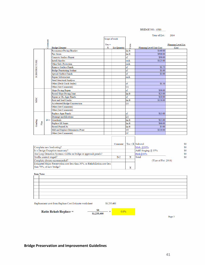
Bridge Preservation and Improvement Guidelines
41

Bridge Recommendation Field Data Br No__________ Date_________ Loc__________ By_________________ Design speed on______mph over_______mph
Adj pavement: Bit Conc Adj shoulder: Bit Conc
Guardrail: Approach 4 corners Loop detectors Y/N
App Panel condition: Overlay Jack R/R Davidson Endpost on AP Relief Jt Paving Br
Catch basin: NE NW SE SW
Deck condition: Cracks every ______ft Delam_________ft2 Scaling ________ ft2
Crack sealing Flood seal Mill & Patch Epoxy Mill & Overlay 2”, 3” Type 1______ ft2 Type 3______ ft2
Rail Condition: Height ______in Retro R/R >9” curb snagging <10 kip Seal
End Post: R/R Approach side only Stand Alone replace
Expansion Joints: Width_______in Temp_______ Regland R/R Modulars Finger Joints
Replace at Abutments Piers Hinges Other________
Sidewalk: crack seal Left________ft Right_________ft Curb height_______in Repair________ft2 R/R
Bottom of Deck Condition: Cracks_______ft Eff at cracks Del removal_______ft2 Epoxy paint
Deck coping condition: Repair_________ft2 Chemical anchor depth______in R/R
Deck Drains: Remove Locations Extensions R/R
Clearance/Damage:
Bearing Condition: Paint Raise Grease R/R Height_______in
Steel Paint Condition: Fascias Freckling Unsound______% Cover pl Y/N Pier Piles Hinges
Pier Cap repair: _________ ft2 Overhangs High stress areas Under bearings Structural an
Column repair: _________ ft2 Outside tie bars Structural an Cathodic protection
Abut Type: Parapet Slab over Parapet Integral Semi-integral Contraction Pile bent
Abutment Cond: Cracks Repair______ft2
Pier Protection Railroad strut Side pier Center pier Other______
Slope Condition: Slope paving_______ ft2 Riprap Flashing at abutment
Concrete surface finish: Abutment Pier Wingwall Coping Railing Fascia beam
Bridge Preservation and Improvement Guidelines
42

Bridge Preservation and Improvement Guidelines
43

Bridge Preservation and Improvement Guidelines
44
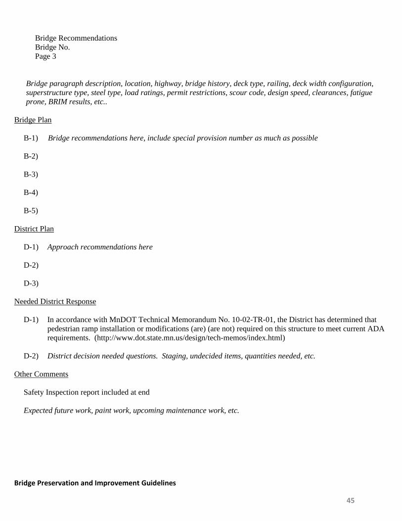
Bridge Recommendations Bridge No. Page 3
Bridge paragraph description, location, highway, bridge history, deck type, railing, deck width configuration, superstructure type, steel type, load ratings, permit restrictions, scour code, design speed, clearances, fatigue prone, BRIM results, etc..
Bridge Plan
B-1) Bridge recommendations here, include special provision number as much as possible B-2) B-3) B-4) B-5)
District Plan D-1) Approach recommendations here D-2) D-3)
Needed District Response
D-1) In accordance with MnDOT Technical Memorandum No. 10-02-TR-01, the District has determined that pedestrian ramp installation or modifications (are) (are not) required on this structure to meet current ADA requirements. (http://www.dot.state.mn.us/design/tech-memos/index.html)
D-2) District decision needed questions. Staging, undecided items, quantities needed, etc.
Other Comments
Safety Inspection report included at end Expected future work, paint work, upcoming maintenance work, etc.
Bridge Preservation and Improvement Guidelines
45

MINNESOTA DEPARTMENT OF TRANSPORTATION
BRIDGE OFFICE
CONTRACT BRIDGE PAINTING RECOMMENDATIONS
BRIDGE NO. T.H. UNDER DIST. NO. Length Span Lengths Rdwy. Width Type Other Features Bridge Designer Tentative Letting Date Steel Surface Area sq.ft. Year Built Weight of Steel lb. Year Last Painted
Based on a field review of the condition of the paint on the above referenced bridge, the following restoration procedures are recommended. If the District concurs in all bridge office recommendations, merely sign in the space provided at the end of the report. (Please return the original copy to the Bridge Office.)
Recommendations By Scope of Work State Bridge Engineer Yes No Comment Paint System Recommended Type of System a) MnDOT 2478 (Organic Zinc-Rich) X b) MnDOT 2479 (Inorganic Zinc-Rich) X c) Other X Surfaces to be Painted a) Structural members X b) Railing X c) Light standards X d) Drains and extensions X e) Bearings X f) Piling X g) Other (See comments) X Surface Preparation a) Commercial Blast Cleaning (SSPC-SP6/NACE No. 3) X b) Brush-Off Blast Cleaning (SSPC-SP7/NACE No. 4) X c) Near White Blast Cleaning (SSPC-SP10/NACE No. 2) X d) Pressure washing at psi X e) Chloride Removal Criteria (See comments) X f) Other (See comments) X Paint Removal (See District Comments) a) Lead-based paint removal X b) Work required over water X
Bridge Preservation and Improvement Guidelines
46

BRIDGE NO.
Recommendations By Scope of Work State Bridge Engineer Yes No Comment Finish Coat Color 1) Brown 2) Light Blue 3) Dark Blue 4) Light Green 5) Dark Green 6) Charcoal Grey 7) Black 8) Other Other Work a) Bearings (See Comments) X a) Other X Recommendations By: , ________Region Br. Engr. Date: Signed State Bridge Engineer Date: The District concurs in all Bridge Office recommendations except as noted on this form. District Comments: 1) MPCA Rule 7025.0250 requires Class containment for paint removal. Signed District Engineer Date:
Bridge Preservation and Improvement Guidelines
47
Contract Bridge Painting Recommendations Bridge No. Page 3 B-1) B-2) B-3) B-4) B-5)
Bridge Preservation and Improvement Guidelines
48

Office of Environmental Services
2015
DETERMINATION OF PAINT SYSTEM ON STEEL BRIDGE STRUCTURES
Bridge Number_________________
LEAD PAINT
It was determined by the following that the existing paint system (does) (does not) contain a lead concentration equal to or greater than 0.5%, 5000 ppm, or 0.5 mg/cm2.
Reviewed Original Plan and Proposal. Reviewed Inventory Records. Reviewed Historical Documents. Sampled and tested the in-place paint system. Average lead content is
____________________________ (attach lab test results).
Signature of Reviewer: ___________________________ Date: ____________
POLLUTION CONTROL FOR LEAD PAINT REMOVAL (Based on Minnesota Rules Chapter 7025)
CONTAINMENT CLASS IV
(Note: MnDOT now only allows Class IV containment)
Signature of Reviewer: ___________________________ Date: ____________
PCB PAINT If the original paint system is pre-1981 determine if the bridge (does) (does not) contain a PCB concentration equal to or greater than 50 ppm, or 50,000 ppb.
Sampled and tested the in-place paint system. Average PCB content is ___________________________ (attach lab test results).
Signature of Reviewer: ___________________________ Date: ____________
Bridge Preservation and Improvement Guidelines
49
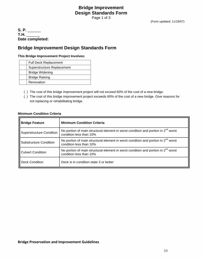
Bridge Improvement Design Standards Form
Page 1 of 3 (Form updated: 11/19/07)
S. P. ______ T.H. ______ Date completed: Bridge Improvement Design Standards Form This Bridge Improvement Project Involves:
Full Deck Replacement Superstructure Replacement Bridge Widening Bridge Raising Renovation
( ) The cost of this bridge improvement project will not exceed 60% of the cost of a new bridge. ( ) The cost of this bridge improvement project exceeds 60% of the cost of a new bridge. Give reasons for
not replacing or rehabilitating bridge.
Minimum Condition Criteria
Bridge Feature Minimum Condition Criteria
Superstructure Condition No portion of main structural element in worst condition and portion in 2nd worst condition less than 10%
Substructure Condition No portion of main structural element in worst condition and portion in 2nd worst condition less than 10%
Culvert Condition No portion of main structural element in worst condition and portion in 2nd worst condition less than 10%
Deck Condition Deck is in condition state 3 or better
Bridge Preservation and Improvement Guidelines
50
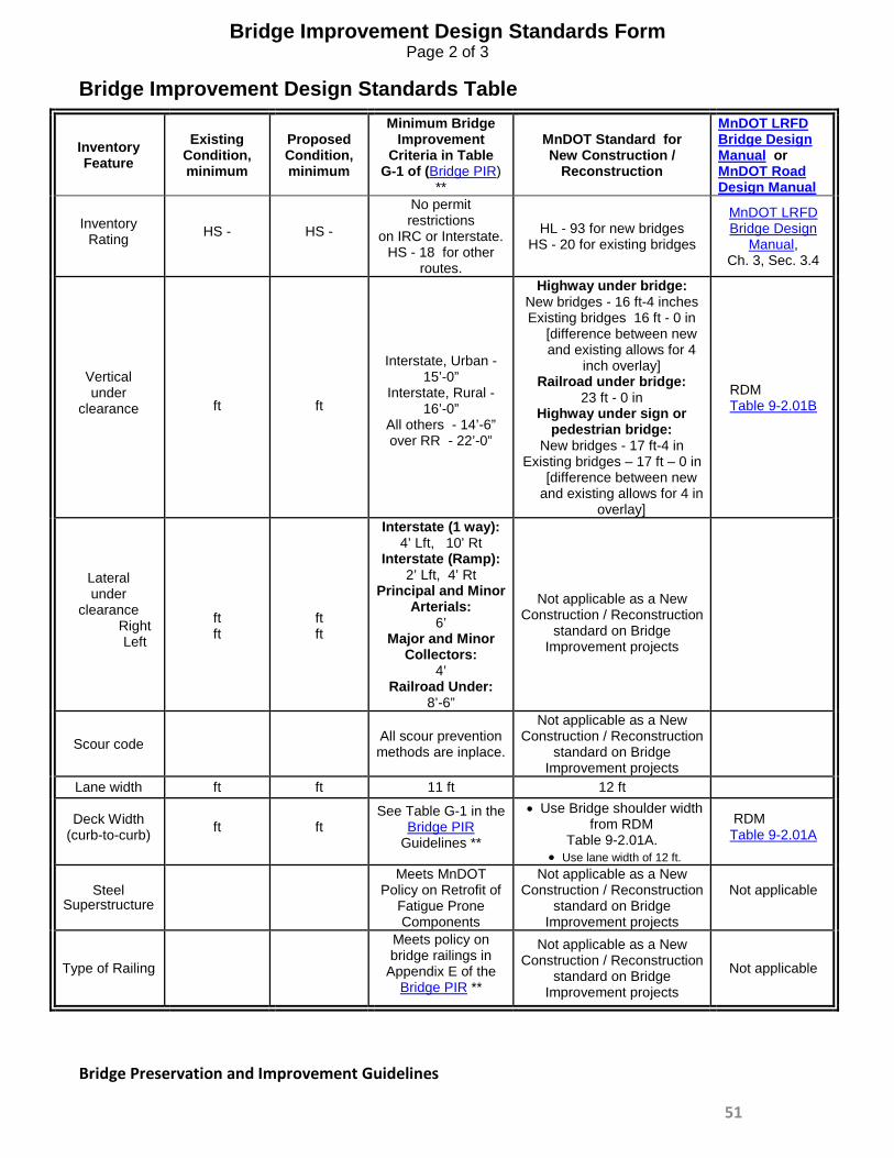
Bridge Improvement Design Standards Form
Page 2 of 3
Bridge Improvement Design Standards Table
Inventory Feature
Existing Condition, minimum
Proposed Condition, minimum
Minimum Bridge Improvement
Criteria in Table G-1 of (Bridge PIR)
**
MnDOT Standard for New Construction /
Reconstruction
MnDOT LRFD Bridge Design Manual or MnDOT Road Design Manual
Inventory Rating HS - HS -
No permit restrictions
on IRC or Interstate. HS - 18 for other
routes.
HL - 93 for new bridges HS - 20 for existing bridges
MnDOT LRFD Bridge Design
Manual, Ch. 3, Sec. 3.4
Vertical under
clearance
ft
ft
Interstate, Urban -
15’-0” Interstate, Rural -
16’-0” All others - 14’-6” over RR - 22’-0”
Highway under bridge: New bridges - 16 ft-4 inches Existing bridges 16 ft - 0 in
[difference between new and existing allows for 4
inch overlay] Railroad under bridge:
23 ft - 0 in Highway under sign or
pedestrian bridge: New bridges - 17 ft-4 in
Existing bridges – 17 ft – 0 in [difference between new
and existing allows for 4 in overlay]
RDM Table 9-2.01B
Lateral under
clearance Right Left
ft ft
ft ft
Interstate (1 way): 4’ Lft, 10’ Rt
Interstate (Ramp): 2’ Lft, 4’ Rt
Principal and Minor Arterials:
6’ Major and Minor
Collectors: 4’
Railroad Under: 8’-6”
Not applicable as a New
Construction / Reconstruction standard on Bridge
Improvement projects
Scour code
All scour prevention
methods are inplace.
Not applicable as a New Construction / Reconstruction
standard on Bridge Improvement projects
Lane width ft ft 11 ft 12 ft
Deck Width (curb-to-curb) ft ft
See Table G-1 in the Bridge PIR
Guidelines **
• Use Bridge shoulder width from RDM
Table 9-2.01A. • Use lane width of 12 ft.
RDM Table 9-2.01A
Steel Superstructure
Meets MnDOT Policy on Retrofit of
Fatigue Prone Components
Not applicable as a New Construction / Reconstruction
standard on Bridge Improvement projects
Not applicable
Type of Railing
Meets policy on bridge railings in
Appendix E of the Bridge PIR **
Not applicable as a New Construction / Reconstruction
standard on Bridge Improvement projects
Not applicable
Bridge Preservation and Improvement Guidelines
51

Bridge Improvement Design Standards Form
Page 3 of 3
* In the tables above, an asterisk preceding a proposed condition indicates a Geometric Design Exception. See Geometric Design Exception Justification below for additional information. ** Bridge PIR: Bridge Preservation, Improvement and Replacement Guidelines If any value listed in the above Design Standards table is less than the Minimum Value in Table G-1 of the Bridge Preservation, Improvement and Replacement Guidelines, a design exception is required. NOTE: For projects using federal HBRRP funding, a Bridge Improvement project must meet the construction standards for a new bridge, as listed in the “MnDOT New Construction/Reconstruction Standards” (column 5) of Table G-1. List of Design Exception(s): Justification of Design Exception(s): Design Exception recommended for approval by: ______________________________________________ State Bridge Engineer Date
Bridge Preservation and Improvement Guidelines
52

Acronym and Definition Acronym Definition
AASHTO Association of American State Highway Transportation Officials
ABC Accelerated Bridge Construction
ADA American Disabilities Act
ADT Average Daily Traffic
ATP Area Transportation Partnerships
ATIP Area Transportation Improvement Program
BDM Bridge Design Manual
BPI Bridge Performance Index
BRIM Bridge Replacement and Improvement Management System
CRU MnDOT Cultural Resource Unit
DRMP District Risk Management Program
ENM Early Notification Memo for Scoping
FCM Fracture Critical Members
Bridge Preservation and Improvement Guidelines
53

Acronym Definition
FHWA Federal Highway Administration
HCADT Heavy Commercial Average Daily Traffic
HIP Highway Investment Plan
HL-93 Highway Loading for LRFD bridge design
HS25 Highway loading for Standard Specifications
LRFD Load and Resistance Factor Design
LRFR Load and Resistance Factor Rating
MAP-21 Federal Transportation Bill of 2012
MASH Manual for Assessing Safety Hardware
MnSHIP Minnesota State Highway Investment Plan
NBI National Bridge Inspection
NBIS National Bridge Inspection Standards
NCHRP National Cooperative Highway Research Program
NHPP National Highway Performance Program
Bridge Preservation and Improvement Guidelines
54

Acronym Definition
NHS National Highway System
NPA Non Principal Arterials
OSOW Over Size Over Weight Superload Corridors
PA Principal Arterials
PM Project Manager
SCOBS AASHTO Subcommittee on Bridges and Structures
SHPO State Historic Preservation Office
SIMS Structural Inventory Management System
SPP Statewide Performance Program
STIP State Transportation Improvement Plan
Bridge Preservation and Improvement Guidelines
55