firebox x peak e-series and firebox x core e-series de ... · firebox® x peak™ e-series...
TRANSCRIPT

Design for Manufacturing and Environment Document
WatchGuard Technologies. Doc #480-2531-001 Rev. A Page 1 of 21
Firebox® X Peak™ e-Series and Firebox® X Core™ e-Series
De-Manufacturing Instructions Document Number: 480-2531-001
Design for Manufacturing and Environment Document
WatchGuard Technologies. Doc #480-2531-001 Rev. A Page 2 of 21
1.0 Purpose This instruction defines the de-manufacturing process for the recovery of this product family as it pertains to recycling of the major product components. 2.0 Scope This instruction applies to the following product family and family part numbers. Product Family Name Family part #’s (not necessarily inclusive) Firebox® X Core™ e-Series Firebox® X550e, X750e, and X1250e; all
revisions
Firebox® X Peak™ e-Series Firebox® X5500e, X6500e, X8500e, and X8500e-F; all revisions
Design for Manufacturing and Environment Document
WatchGuard Technologies. Doc #480-2531-001 Rev. A Page 3 of 21
3.0 Instruction 3.1 -Remove labels
Material removed (part Desc or P/N & material type)
Instruction visual
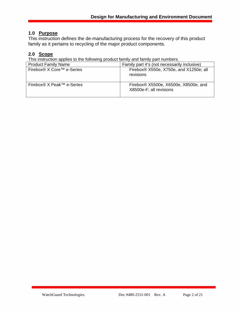
Labels
Cert. label: 277-2265-042– Metalized poly-film; 1 ea.
Labels Input power: 277-1270-003 - Metalized Poly-film; 1 ea.
Labels P/N FWA: No WG part number - Metalized Poly-film; 1 ea.
Labels ODM Bar Code: 282-2089-001 - Poly-film; 1 ea. Warranty Void: 277-0230-001 – Poly-film; 1 ea. Product UPC/Serial: 281-10xx-001 - Poly-film; 1 ea.
Remove label
Remove label
Remove label
Remove labels
Design for Manufacturing and Environment Document
WatchGuard Technologies. Doc #480-2531-001 Rev. A Page 4 of 21
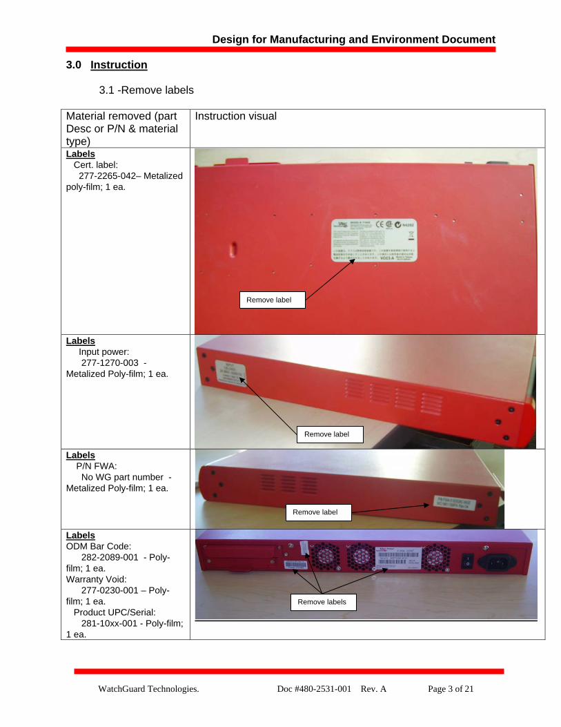
3.2 –Remove side and back screws holding upper chassis to lower, and disengage halves
Material removed (part Desc or P/N & material type)
Instruction visual
Screws 200-4705-042 - Philips sink head; black; 12 ea.
Screws 200-4505-042 - Philips drive; pan head, Nickel; 2 ea.
Chassis Top 212-2582-001- galvanized steel w/powder coat paint
Disengage by sliding top off bottom
Remove screws; 6 ea.; two sides
Remove screws; 2 ea.; back
Design for Manufacturing and Environment Document
WatchGuard Technologies. Doc #480-2531-001 Rev. A Page 5 of 21
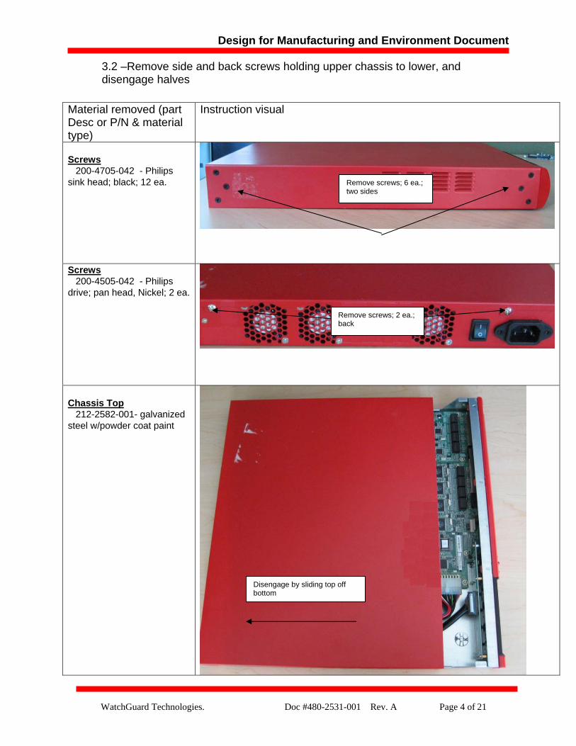
3.3 –Remove Lexan Insulator from Chassis Top
Material removed (P/N & material type)
Instruction visual
Chassis Top 212-2582-001- galvanized steel w/powder coat paint Lexan insulator 225-2588-005- Lexan; 11x18cm w/adhesive; 1 ea.
Remove Lexan 1 ea.
Design for Manufacturing and Environment Document
WatchGuard Technologies. Doc #480-2531-001 Rev. A Page 6 of 21
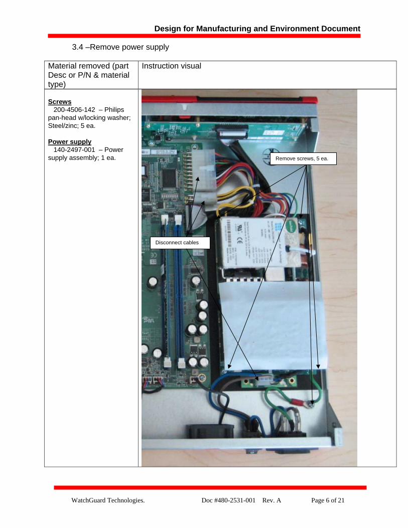
3.4 –Remove power supply
Screws 200-4506-142 – Philips pan-head w/locking washer; Steel/zinc; 5 ea. Power supply 140-2497-001 – Power supply assembly; 1 ea.
Material removed (part Desc or P/N & material type)
Instruction visual
Disconnect cables
Remove screws, 5 ea.
Design for Manufacturing and Environment Document
WatchGuard Technologies. Doc #480-2531-001 Rev. A Page 7 of 21
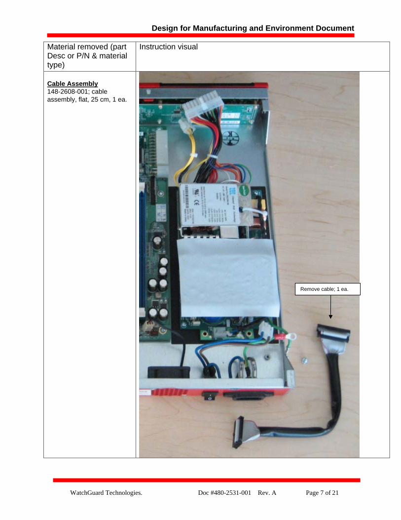
Material removed (part Desc or P/N & material type)
Instruction visual
Cable Assembly 148-2608-001; cable assembly, flat, 25 cm, 1 ea.
Remove cable; 1 ea.
Design for Manufacturing and Environment Document
WatchGuard Technologies. Doc #480-2531-001 Rev. A Page 8 of 21
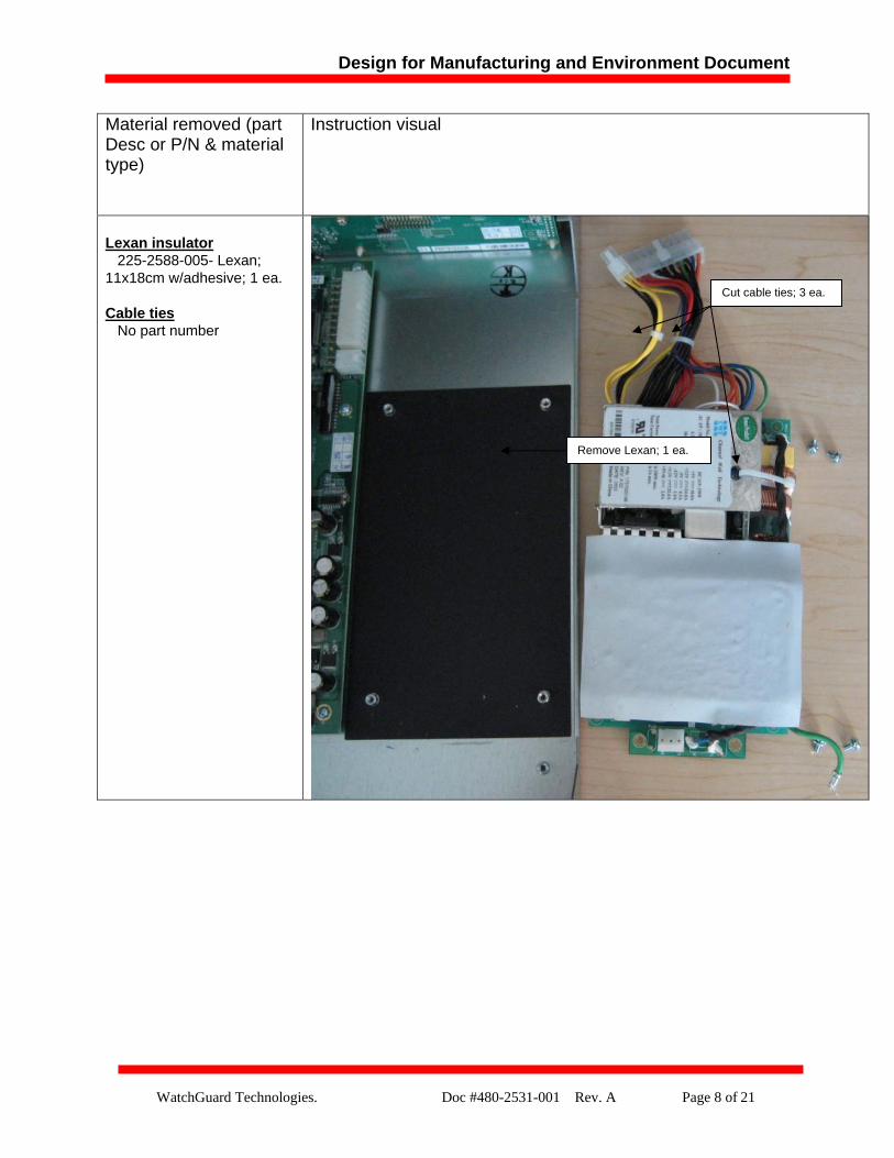
Material removed (part Desc or P/N & material type)
Instruction visual
Lexan insulator 225-2588-005- Lexan; 11x18cm w/adhesive; 1 ea.
Cable ties No part number
Cut cable ties; 3 ea.
Remove Lexan; 1 ea.
Design for Manufacturing and Environment Document
WatchGuard Technologies. Doc #480-2531-001 Rev. A Page 9 of 21
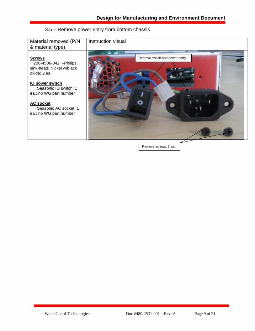
3.5 – Remove power entry from bottom chassis
Material removed (P/N & material type)
Instruction visual
Screws 200-4506-042 –Philips sink-head; Nickel w/black oxide; 2 ea. IO power switch Seasonic IO switch; 1 ea.; no WG part number AC socket Seasonic AC socket; 1 ea.; no WG part number
Remove switch and power entry
Remove screws, 2 ea.
Design for Manufacturing and Environment Document
WatchGuard Technologies. Doc #480-2531-001 Rev. A Page 10 of 21
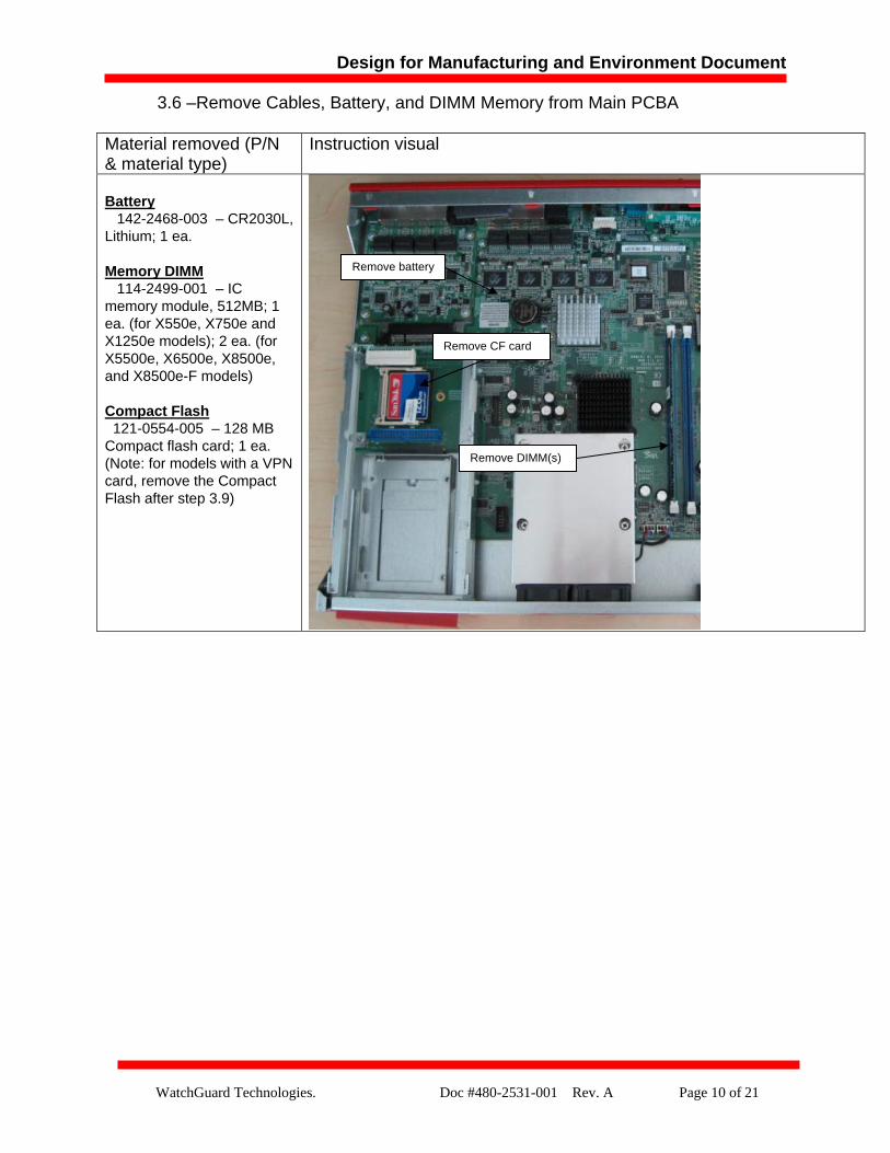
3.6 –Remove Cables, Battery, and DIMM Memory from Main PCBA
Material removed (P/N & material type)
Instruction visual
Battery 142-2468-003 – CR2030L, Lithium; 1 ea.
Memory DIMM 114-2499-001 – IC memory module, 512MB; 1 ea. (for X550e, X750e and X1250e models); 2 ea. (for X5500e, X6500e, X8500e, and X8500e-F models) Compact Flash 121-0554-005 – 128 MB Compact flash card; 1 ea. (Note: for models with a VPN card, remove the Compact Flash after step 3.9)
Remove battery
Remove DIMM(s)
Remove CF card

Design for Manufacturing and Environment Document
WatchGuard Technologies. Doc #480-2531-001 Rev. A Page 11 of 21
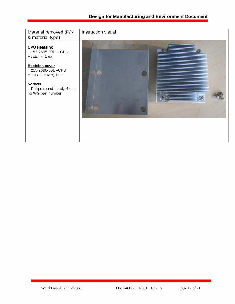
3.7 – Remove Heat sink and Heat Sink Cover
Material removed (P/N & material type)
Instruction visual
Heatsink cover 215-2696-001 –CPU Heatsink cover; 1 ea.
Remove screws, both sides, 2 ea.
Unscrew four points
Design for Manufacturing and Environment Document
WatchGuard Technologies. Doc #480-2531-001 Rev. A Page 12 of 21
Material removed (P/N & material type)
Instruction visual
CPU Heatsink 152-2695-001 – CPU Heatsink; 1 ea. Heatsink cover 215-2696-001 –CPU Heatsink cover; 1 ea. Screws Philips round-head; 4 ea; no WG part number
Design for Manufacturing and Environment Document
WatchGuard Technologies. Doc #480-2531-001 Rev. A Page 13 of 21
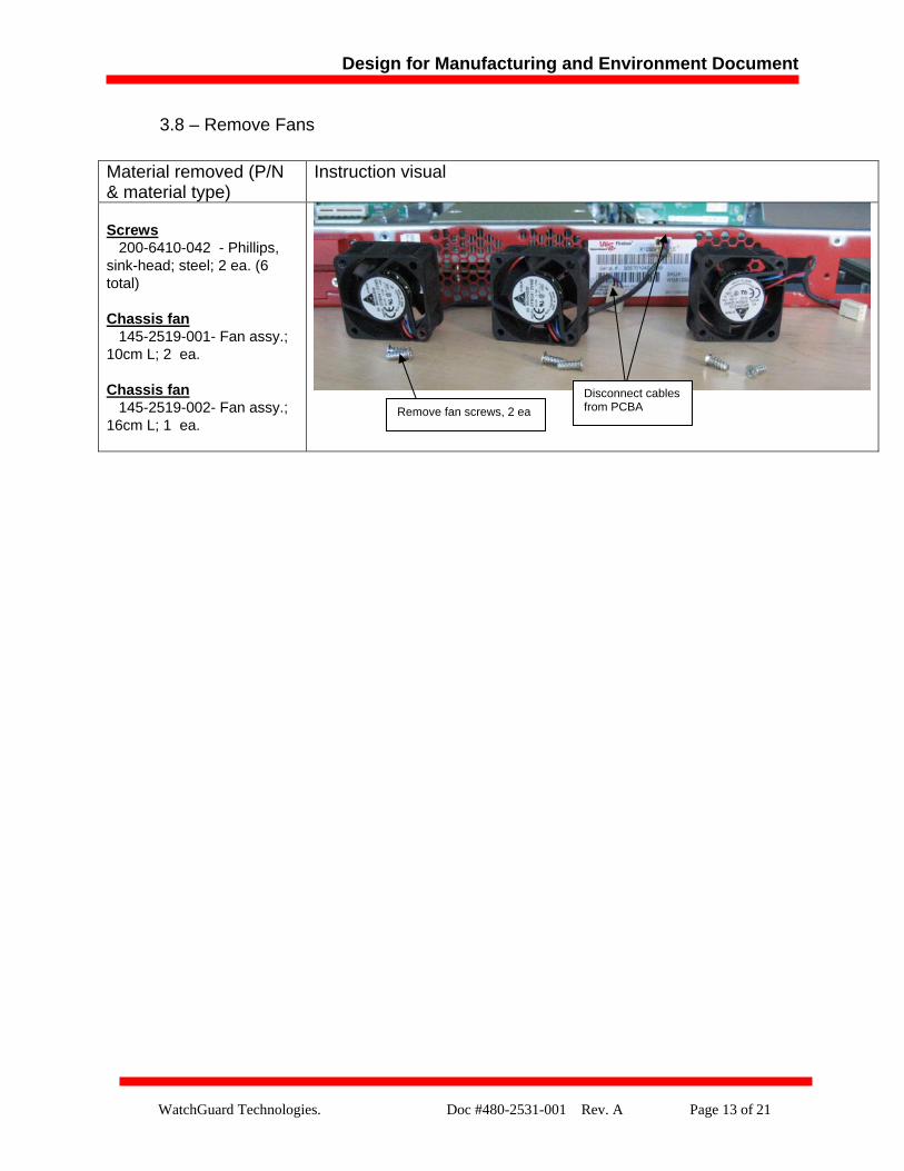
3.8 – Remove Fans
Material removed (P/N & material type)
Instruction visual
Screws
200-6410-042 - Phillips, sink-head; steel; 2 ea. (6 total) Chassis fan 145-2519-001- Fan assy.; 10cm L; 2 ea. Chassis fan 145-2519-002- Fan assy.; 16cm L; 1 ea.
Disconnect cables from PCBA Remove fan screws, 2 ea
Design for Manufacturing and Environment Document
WatchGuard Technologies. Doc #480-2531-001 Rev. A Page 14 of 21
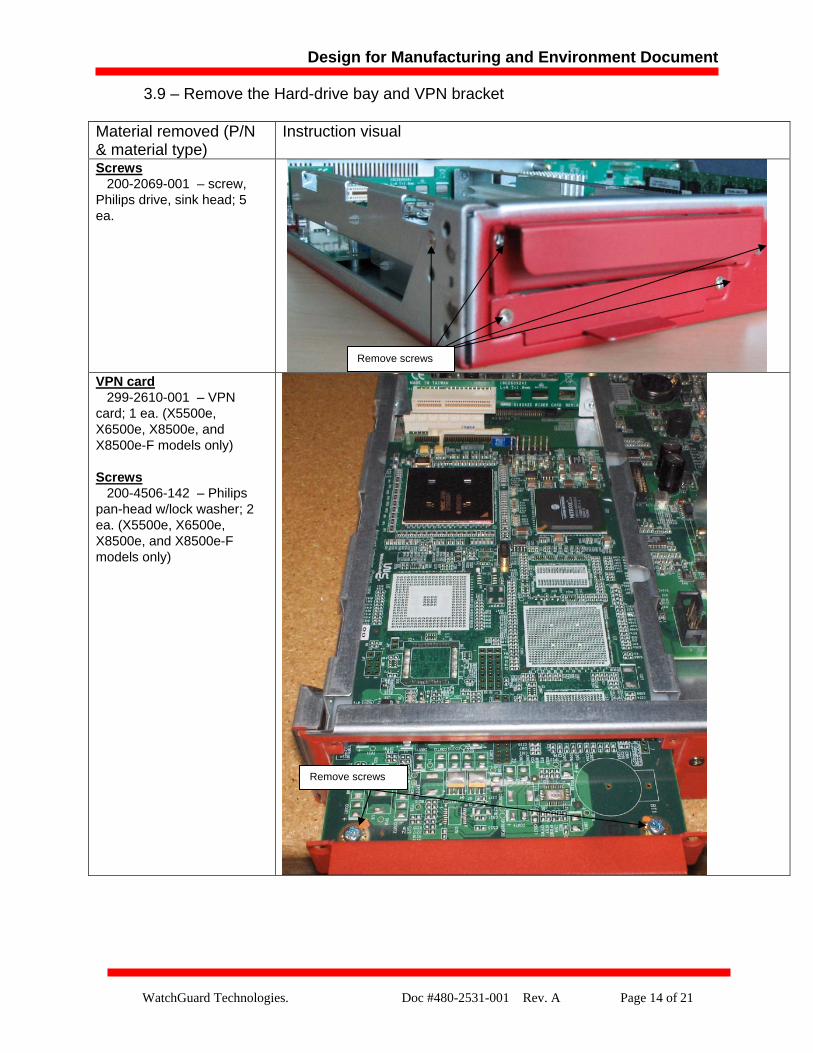
3.9 – Remove the Hard-drive bay and VPN bracket
Material removed (P/N & material type)
Instruction visual
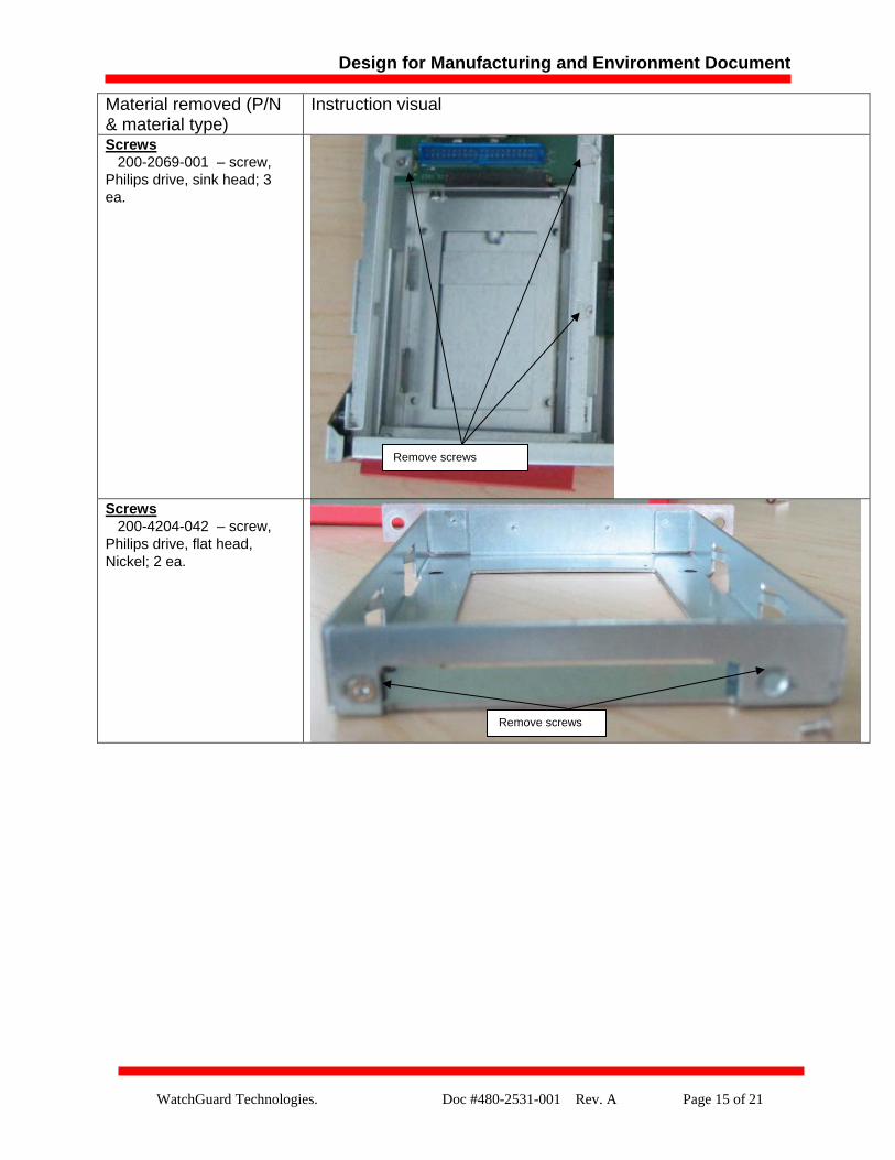
Screws
200-2069-001 – screw, Philips drive, sink head; 5 ea.
Remove screws
VPN card 299-2610-001 – VPN card; 1 ea. (X5500e, X6500e, X8500e, and X8500e-F models only) Screws 200-4506-142 – Philips pan-head w/lock washer; 2 ea. (X5500e, X6500e, X8500e, and X8500e-F models only)
Remove screws
Design for Manufacturing and Environment Document
WatchGuard Technologies. Doc #480-2531-001 Rev. A Page 15 of 21
Material removed (P/N & material type)
Instruction visual
Screws 200-2069-001 – screw, Philips drive, sink head; 3 ea.
Remove screws
Screws 200-4204-042 – screw, Philips drive, flat head, Nickel; 2 ea.
Remove screws
Design for Manufacturing and Environment Document
WatchGuard Technologies. Doc #480-2531-001 Rev. A Page 16 of 21
Material removed (P/N & material type)
Instruction visual
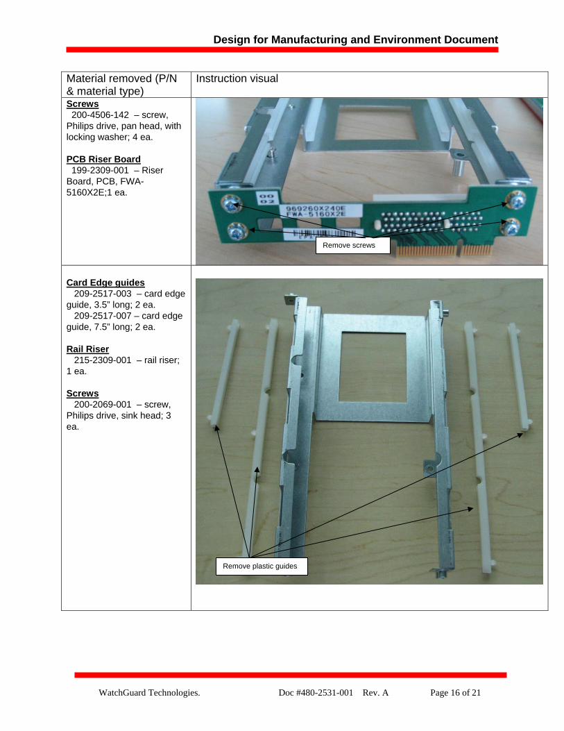
Screws
200-4506-142 – screw, Philips drive, pan head, with locking washer; 4 ea. PCB Riser Board 199-2309-001 – Riser Board, PCB, FWA-5160X2E;1 ea.
Remove screws
Card Edge guides 209-2517-003 – card edge guide, 3.5” long; 2 ea. 209-2517-007 – card edge guide, 7.5” long; 2 ea. Rail Riser 215-2309-001 – rail riser; 1 ea. Screws 200-2069-001 – screw, Philips drive, sink head; 3 ea.
Remove plastic guides
Design for Manufacturing and Environment Document
WatchGuard Technologies. Doc #480-2531-001 Rev. A Page 17 of 21
3.10 – Remove Main PCBA from Bottom Chassis and remove Lan-A or Lan-B boards (as applicable)
Material removed (P/N & material type)
Instruction visual
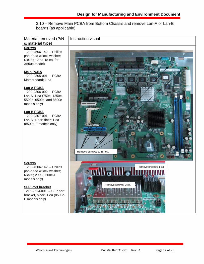
Screws 200-4506-142 – Philips pan-head w/lock washer; Nickel; 12 ea. (8 ea. for X550e model)
Main PCBA 299-2305-001 – PCBA Motherboard; 1 ea Lan A PCBA 299-2306-002 – PCBA Lan A; 1 ea (750e, 1250e, 5500e, 6500e, and 8500e models only) Lan B PCBA 299-2307-001 – PCBA Lan B, 4-port fiber; 1 ea (8500e-F models only)
Remove screws; 12 (8) ea.
Screws 200-4506-142 – Philips pan-head w/lock washer; Nickel; 2 ea (8500e-F models only) SFP Port bracket 215-2614-001 – SFP port bracket, black; 1 ea (8500e-F models only)
Remove bracket; 1 ea.
Remove screws; 2 ea.
Design for Manufacturing and Environment Document
WatchGuard Technologies. Doc #480-2531-001 Rev. A Page 18 of 21
Material removed (P/N & material type)
Instruction visual
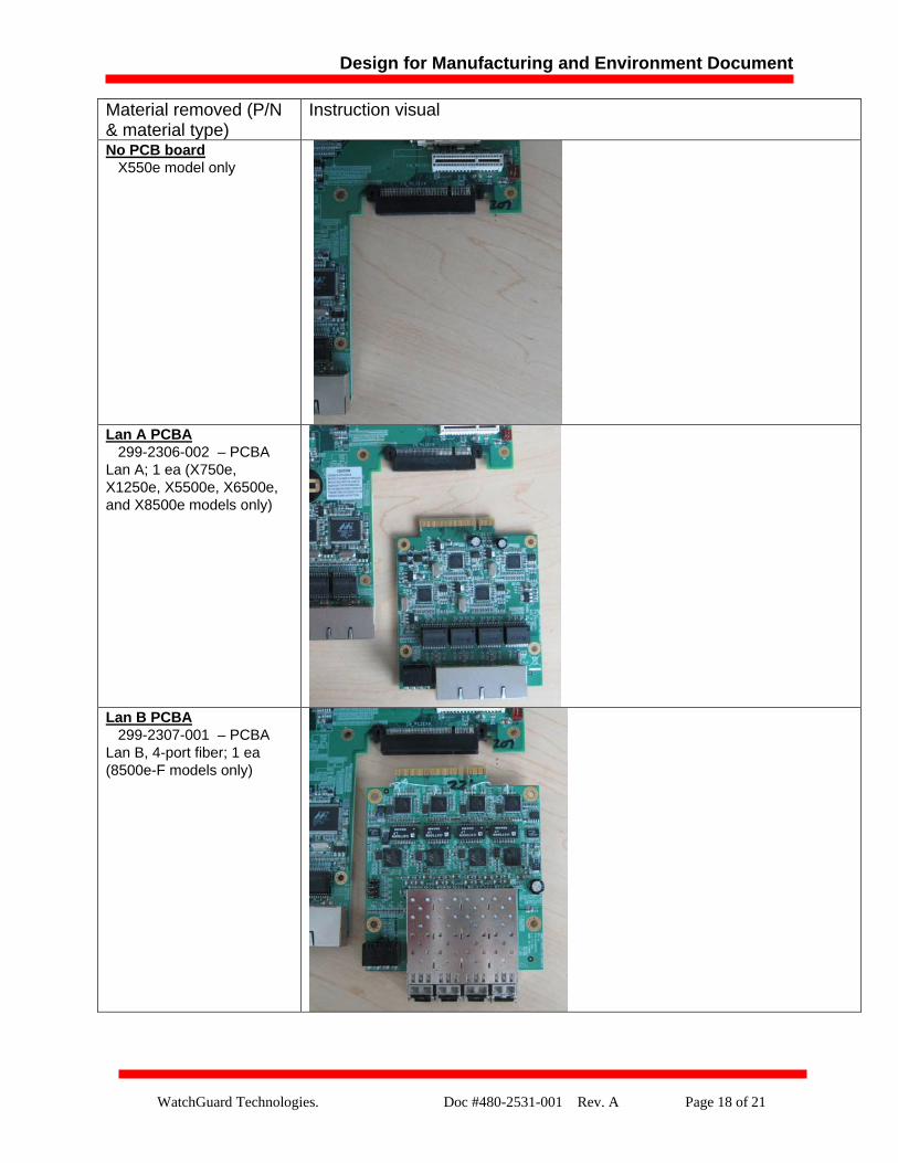
No PCB board
X550e model only
Lan A PCBA 299-2306-002 – PCBA Lan A; 1 ea (X750e, X1250e, X5500e, X6500e, and X8500e models only)
Lan B PCBA 299-2307-001 – PCBA Lan B, 4-port fiber; 1 ea (8500e-F models only)
Design for Manufacturing and Environment Document
WatchGuard Technologies. Doc #480-2531-001 Rev. A Page 19 of 21
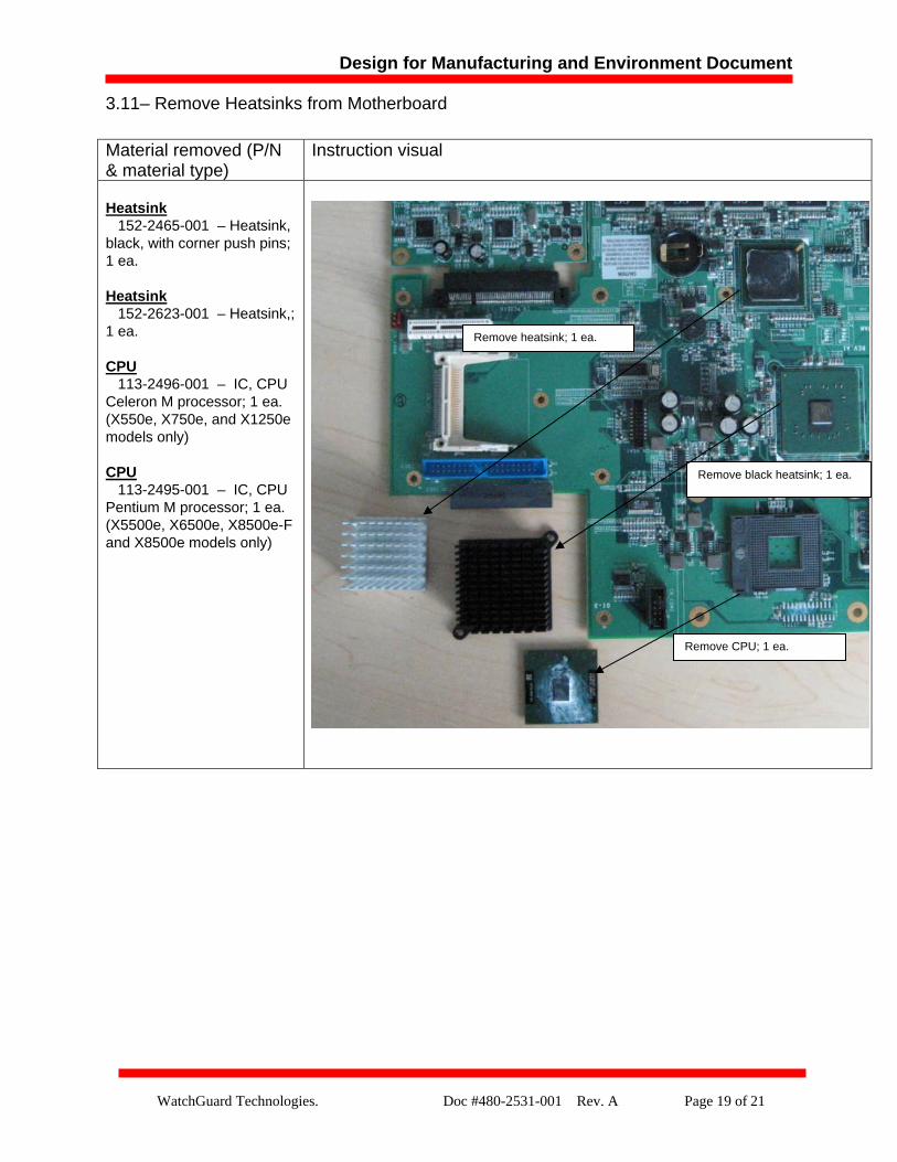
3.11– Remove Heatsinks from Motherboard Material removed (P/N & material type)
Instruction visual
Heatsink
152-2465-001 – Heatsink, black, with corner push pins; 1 ea. Heatsink 152-2623-001 – Heatsink,; 1 ea. CPU 113-2496-001 – IC, CPU Celeron M processor; 1 ea. (X550e, X750e, and X1250e models only) CPU 113-2495-001 – IC, CPU Pentium M processor; 1 ea. (X5500e, X6500e, X8500e-F and X8500e models only)
Remove heatsink; 1 ea.
Remove black heatsink; 1 ea.
Remove CPU; 1 ea.
Design for Manufacturing and Environment Document
WatchGuard Technologies. Doc #480-2531-001 Rev. A Page 20 of 21
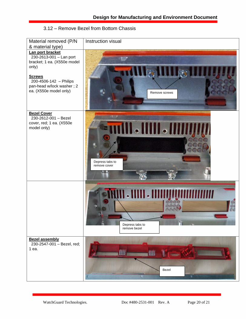
3.12 – Remove Bezel from Bottom Chassis
Material removed (P/N & material type)
Instruction visual
Lan port bracket
230-2613-001 – Lan port bracket; 1 ea. (X550e model only) Screws 200-4506-142 – Philips pan-head w/lock washer ; 2 ea. (X550e model only)
Bezel Cover 230-2612-001 – Bezel cover, red; 1 ea. (X550e model only)
Bezel assembly 230-2547-001 – Bezel, red; 1 ea.
Remove screws
Depress tabs to remove cover
Depress tabs to remove bezel
Bezel
Design for Manufacturing and Environment Document
WatchGuard Technologies. Doc #480-2531-001 Rev. A Page 21 of 21
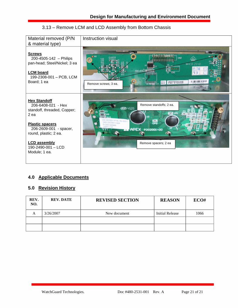
3.13 – Remove LCM and LCD Assembly from Bottom Chassis
Material removed (P/N & material type)
Instruction visual
Screws
4.0 Applicable Documents
5.0 Revision History REV. NO.
REV. DATE REVISED SECTION REASON ECO#
A 3/26/2007 New document Initial Release 1066
200-4505-142 – Philips pan-head; Steel/Nickel; 3 ea LCM board 199-2308-001 – PCB, LCM Board; 1 ea
Remove screws; 3 ea.
Hex Standoff 206-6408-021 - Hex standoff, threaded, Copper; 2 ea Plastic spacers 206-2609-001 - spacer, round, plastic; 2 ea. LCD assembly 190-2490-001 – LCD Module; 1 ea.
Remove standoffs; 2 ea.
Remove spacers; 2 ea