fire resistance test furnaces brochures... · ftt fire resistance test furnaces will enable test...
TRANSCRIPT
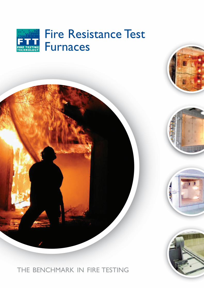
Fire Resistance TestFurnaces
THE BENCHMARK IN FIRE TESTING
FTT Fire Resistance Test Furnaces will enable test houses and
manufacturers to meet the regulatory testing requirements of fire
resistance testing.The range provides vertical, horizontal and indicative
testing, fully complementing our reaction-to-fire testing equipment used in
manufacturing facilities and laboratories worldwide.
The performance of walls, columns, floors and other building elements when exposed to
fire conditions is of extreme importance in ensuring safety to both the public and
neighbouring structures. In order to acquire information on this performance, it is
necessary to measure the fire-resistive properties of the materials and assemblies in
question. Building elements commonly tested include:
The regulatory requirement for fire resistance testing for these types of product is set
out in many international standards.The standards are outlined for each furnace type
below. Our fire resistance test furnaces are built to or exceed the existing requirements
of all of these tests.
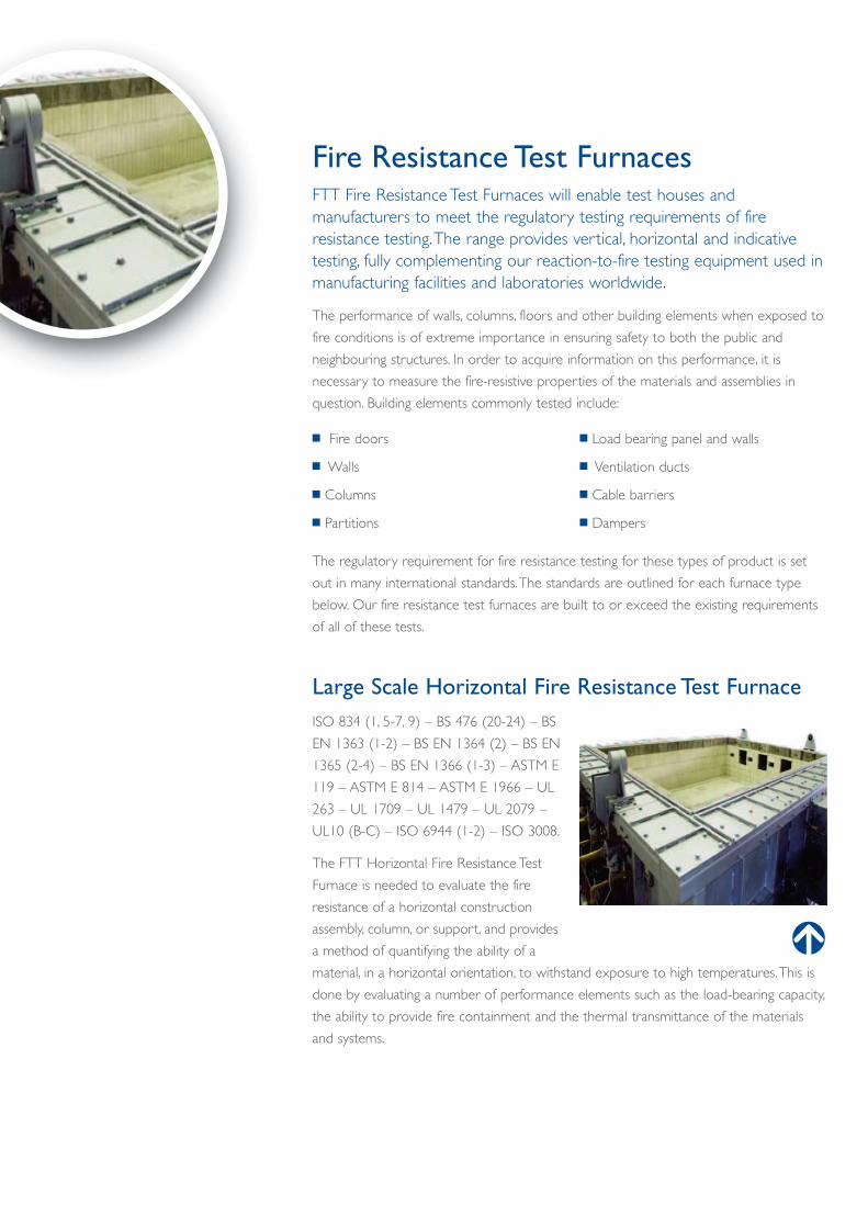
Large Scale Horizontal Fire Resistance Test Furnace
ISO 834 (1, 5-7, 9) – BS 476 (20-24) – BS
EN 1363 (1-2) – BS EN 1364 (2) – BS EN
1365 (2-4) – BS EN 1366 (1-3) – ASTM E
119 – ASTM E 814 – ASTM E 1966 – UL
263 – UL 1709 – UL 1479 – UL 2079 –
UL10 (B-C) – ISO 6944 (1-2) – ISO 3008.
The FTT Horizontal Fire Resistance Test
Furnace is needed to evaluate the fire
resistance of a horizontal construction
assembly, column, or support, and provides
a method of quantifying the ability of a
material, in a horizontal orientation, to withstand exposure to high temperatures.This is
done by evaluating a number of performance elements such as the load-bearing capacity,
the ability to provide fire containment and the thermal transmittance of the materials
and systems.
Fire Resistance Test Furnaces
n Fire doors
n Walls
n Columns
n Partitions
n Load bearing panel and walls
n Ventilation ducts
n Cable barriers
n Dampers
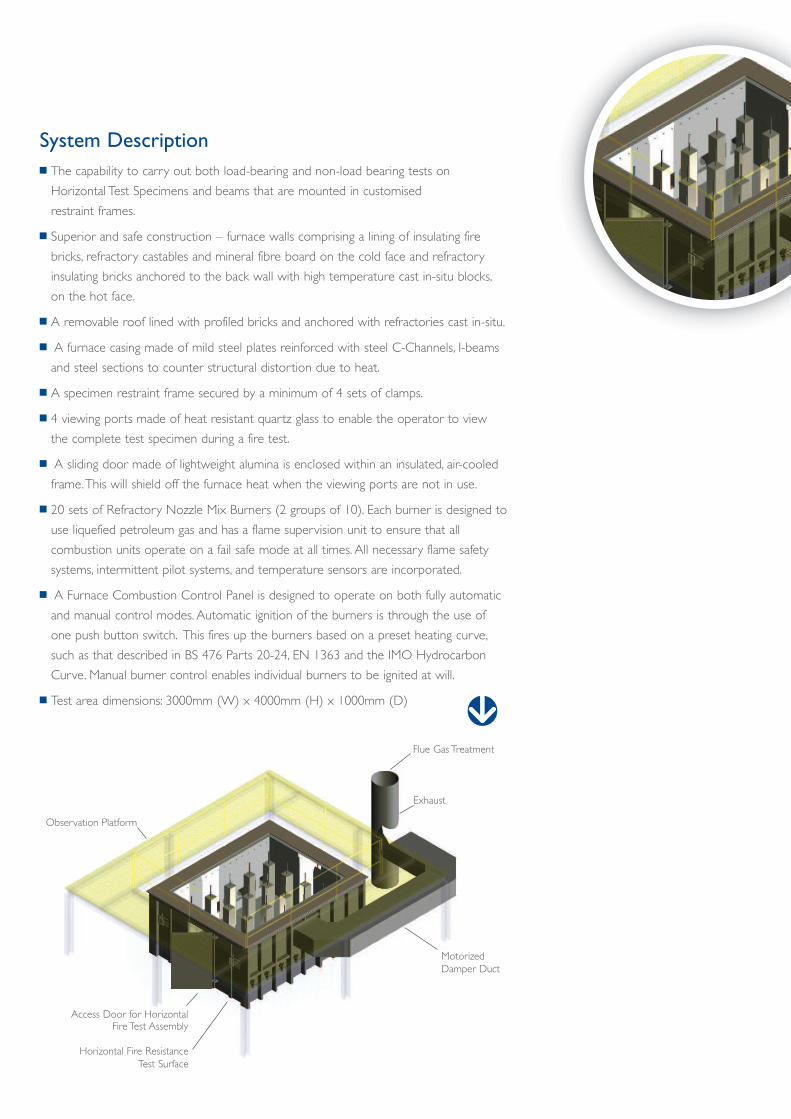
System Description
n The capability to carry out both load-bearing and non-load bearing tests on
Horizontal Test Specimens and beams that are mounted in customised
restraint frames.
n Superior and safe construction – furnace walls comprising a lining of insulating fire
bricks, refractory castables and mineral fibre board on the cold face and refractory
insulating bricks anchored to the back wall with high temperature cast in-situ blocks,
on the hot face.
n A removable roof lined with profiled bricks and anchored with refractories cast in-situ.
n A furnace casing made of mild steel plates reinforced with steel C-Channels, I-beams
and steel sections to counter structural distortion due to heat.
n A specimen restraint frame secured by a minimum of 4 sets of clamps.
n 4 viewing ports made of heat resistant quartz glass to enable the operator to view
the complete test specimen during a fire test.
n A sliding door made of lightweight alumina is enclosed within an insulated, air-cooled
frame.This will shield off the furnace heat when the viewing ports are not in use.
n 20 sets of Refractory Nozzle Mix Burners (2 groups of 10). Each burner is designed to
use liquefied petroleum gas and has a flame supervision unit to ensure that all
combustion units operate on a fail safe mode at all times. All necessary flame safety
systems, intermittent pilot systems, and temperature sensors are incorporated.
n A Furnace Combustion Control Panel is designed to operate on both fully automatic
and manual control modes. Automatic ignition of the burners is through the use of
one push button switch. This fires up the burners based on a preset heating curve,
such as that described in BS 476 Parts 20-24, EN 1363 and the IMO Hydrocarbon
Curve. Manual burner control enables individual burners to be ignited at will.
n Test area dimensions: 3000mm (W) x 4000mm (H) x 1000mm (D)
Observation Platform
Access Door for HorizontalFire Test Assembly
Horizontal Fire Resistance
Test Surface
Motorized
Damper Duct
Exhaust
Flue Gas Treatment
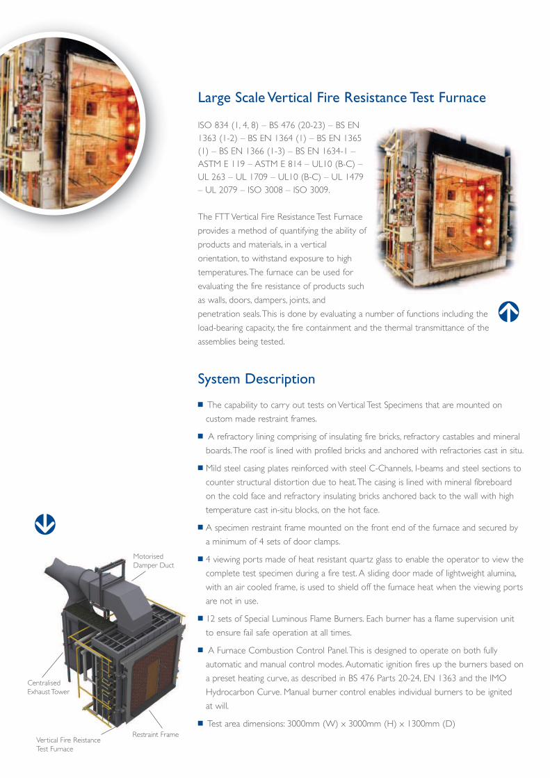
Large Scale Vertical Fire Resistance Test Furnace
ISO 834 (1, 4, 8) – BS 476 (20-23) – BS EN
1363 (1-2) – BS EN 1364 (1) – BS EN 1365
(1) – BS EN 1366 (1-3) – BS EN 1634-1 –
ASTM E 119 – ASTM E 814 – UL10 (B-C) –
UL 263 – UL 1709 – UL10 (B-C) – UL 1479
– UL 2079 – ISO 3008 – ISO 3009.
The FTT Vertical Fire Resistance Test Furnace
provides a method of quantifying the ability of
products and materials, in a vertical
orientation, to withstand exposure to high
temperatures.The furnace can be used for
evaluating the fire resistance of products such
as walls, doors, dampers, joints, and
penetration seals.This is done by evaluating a number of functions including the
load-bearing capacity, the fire containment and the thermal transmittance of the
assemblies being tested.
System Description
n The capability to carry out tests on Vertical Test Specimens that are mounted on
custom made restraint frames.
n A refractory lining comprising of insulating fire bricks, refractory castables and mineral
boards.The roof is lined with profiled bricks and anchored with refractories cast in situ.
n Mild steel casing plates reinforced with steel C-Channels, I-beams and steel sections to
counter structural distortion due to heat.The casing is lined with mineral fibreboard
on the cold face and refractory insulating bricks anchored back to the wall with high
temperature cast in-situ blocks, on the hot face.
n A specimen restraint frame mounted on the front end of the furnace and secured by
a minimum of 4 sets of door clamps.
n 4 viewing ports made of heat resistant quartz glass to enable the operator to view the
complete test specimen during a fire test. A sliding door made of lightweight alumina,
with an air cooled frame, is used to shield off the furnace heat when the viewing ports
are not in use.
n 12 sets of Special Luminous Flame Burners. Each burner has a flame supervision unit
to ensure fail safe operation at all times.
n A Furnace Combustion Control Panel.This is designed to operate on both fully
automatic and manual control modes. Automatic ignition fires up the burners based on
a preset heating curve, as described in BS 476 Parts 20-24, EN 1363 and the IMO
Hydrocarbon Curve. Manual burner control enables individual burners to be ignited
at will.
n Test area dimensions: 3000mm (W) x 3000mm (H) x 1300mm (D)
Motorised
Damper Duct
Centralised
Exhaust Tower
Vertical Fire Reistance
Test Furnace
Restraint Frame
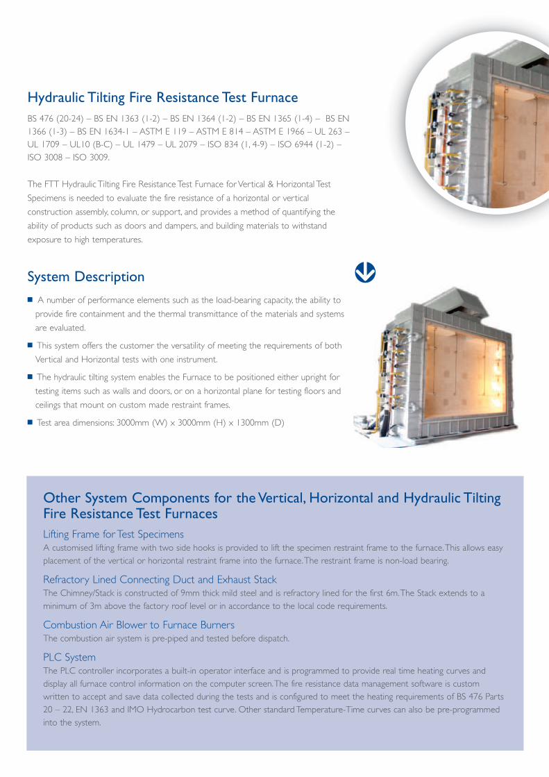
Hydraulic Tilting Fire Resistance Test Furnace
BS 476 (20-24) – BS EN 1363 (1-2) – BS EN 1364 (1-2) – BS EN 1365 (1-4) – BS EN
1366 (1-3) – BS EN 1634-1 – ASTM E 119 – ASTM E 814 – ASTM E 1966 – UL 263 –
UL 1709 – UL10 (B-C) – UL 1479 – UL 2079 – ISO 834 (1, 4-9) – ISO 6944 (1-2) –
ISO 3008 – ISO 3009.
The FTT Hydraulic Tilting Fire Resistance Test Furnace for Vertical & Horizontal Test
Specimens is needed to evaluate the fire resistance of a horizontal or vertical
construction assembly, column, or support, and provides a method of quantifying the
ability of products such as doors and dampers, and building materials to withstand
exposure to high temperatures.
System Description
n A number of performance elements such as the load-bearing capacity, the ability to
provide fire containment and the thermal transmittance of the materials and systems
are evaluated.
n This system offers the customer the versatility of meeting the requirements of both
Vertical and Horizontal tests with one instrument.
n The hydraulic tilting system enables the Furnace to be positioned either upright for
testing items such as walls and doors, or on a horizontal plane for testing floors and
ceilings that mount on custom made restraint frames.
n Test area dimensions: 3000mm (W) x 3000mm (H) x 1300mm (D)
Other System Components for the Vertical, Horizontal and Hydraulic TiltingFire Resistance Test Furnaces
Lifting Frame for Test Specimens
A customised lifting frame with two side hooks is provided to lift the specimen restraint frame to the furnace.This allows easy
placement of the vertical or horizontal restraint frame into the furnace.The restraint frame is non-load bearing.
Refractory Lined Connecting Duct and Exhaust Stack
The Chimney/Stack is constructed of 9mm thick mild steel and is refractory lined for the first 6m.The Stack extends to a
minimum of 3m above the factory roof level or in accordance to the local code requirements.
Combustion Air Blower to Furnace Burners
The combustion air system is pre-piped and tested before dispatch.
PLC System
The PLC controller incorporates a built-in operator interface and is programmed to provide real time heating curves and
display all furnace control information on the computer screen.The fire resistance data management software is custom
written to accept and save data collected during the tests and is configured to meet the heating requirements of BS 476 Parts
20 – 22, EN 1363 and IMO Hydrocarbon test curve. Other standard Temperature-Time curves can also be pre-programmed
into the system.
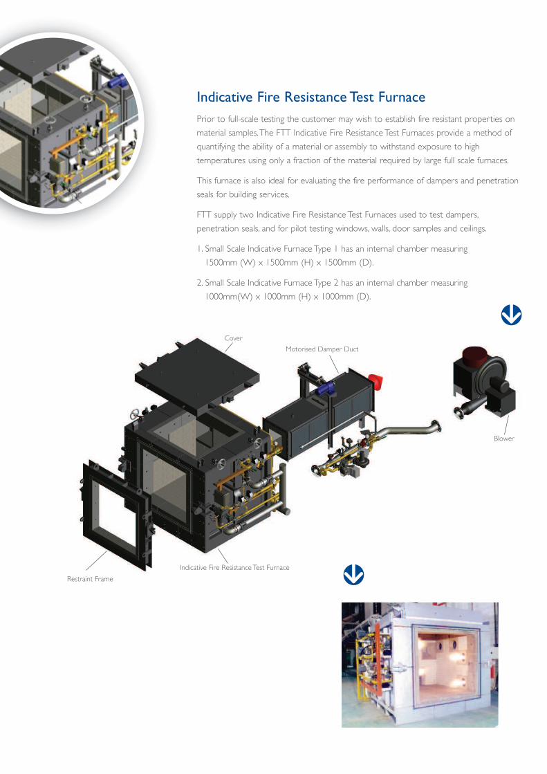
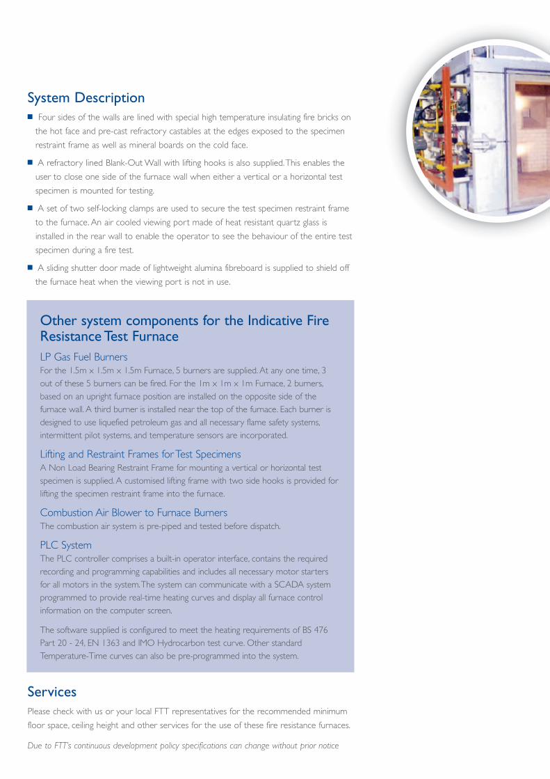
Indicative Fire Resistance Test Furnace
Prior to full-scale testing the customer may wish to establish fire resistant properties on
material samples.The FTT Indicative Fire Resistance Test Furnaces provide a method of
quantifying the ability of a material or assembly to withstand exposure to high
temperatures using only a fraction of the material required by large full scale furnaces.
This furnace is also ideal for evaluating the fire performance of dampers and penetration
seals for building services.
FTT supply two Indicative Fire Resistance Test Furnaces used to test dampers,
penetration seals, and for pilot testing windows, walls, door samples and ceilings.
1. Small Scale Indicative Furnace Type 1 has an internal chamber measuring
1500mm (W) x 1500mm (H) x 1500mm (D).
2. Small Scale Indicative Furnace Type 2 has an internal chamber measuring
1000mm(W) x 1000mm (H) x 1000mm (D).
Restraint Frame
Indicative Fire Resistance Test Furnace
Blower
Motorised Damper Duct
Cover
Other system components for the Indicative FireResistance Test Furnace
LP Gas Fuel Burners
For the 1.5m x 1.5m x 1.5m Furnace, 5 burners are supplied. At any one time, 3
out of these 5 burners can be fired. For the 1m x 1m x 1m Furnace, 2 burners,
based on an upright furnace position are installed on the opposite side of the
furnace wall. A third burner is installed near the top of the furnace. Each burner is
designed to use liquefied petroleum gas and all necessary flame safety systems,
intermittent pilot systems, and temperature sensors are incorporated.
Lifting and Restraint Frames for Test Specimens
A Non Load Bearing Restraint Frame for mounting a vertical or horizontal test
specimen is supplied. A customised lifting frame with two side hooks is provided for
lifting the specimen restraint frame into the furnace.
Combustion Air Blower to Furnace Burners
The combustion air system is pre-piped and tested before dispatch.
PLC System
The PLC controller comprises a built-in operator interface, contains the required
recording and programming capabilities and includes all necessary motor starters
for all motors in the system.The system can communicate with a SCADA system
programmed to provide real-time heating curves and display all furnace control
information on the computer screen.
The software supplied is configured to meet the heating requirements of BS 476
Part 20 - 24, EN 1363 and IMO Hydrocarbon test curve. Other standard
Temperature-Time curves can also be pre-programmed into the system.
System Descriptionn Four sides of the walls are lined with special high temperature insulating fire bricks on
the hot face and pre-cast refractory castables at the edges exposed to the specimen
restraint frame as well as mineral boards on the cold face.
n A refractory lined Blank-Out Wall with lifting hooks is also supplied.This enables the
user to close one side of the furnace wall when either a vertical or a horizontal test
specimen is mounted for testing.
n A set of two self-locking clamps are used to secure the test specimen restraint frame
to the furnace. An air cooled viewing port made of heat resistant quartz glass is
installed in the rear wall to enable the operator to see the behaviour of the entire test
specimen during a fire test.
n A sliding shutter door made of lightweight alumina fibreboard is supplied to shield off
the furnace heat when the viewing port is not in use.
Services
Please check with us or your local FTT representatives for the recommended minimum
floor space, ceiling height and other services for the use of these fire resistance furnaces.
Due to FTT’s continuous development policy specifications can change without prior notice

Charlwoods Road
East Grinstead
West Sussex RH19 2HL United Kingdom
Tel: +44 (0)1342 323600
Fax: +44 (0)1342 323608
email: [email protected]
web: www.fire-testing.com
fire testing technology limited