fire detection and alarm system - cormeton electronics€¦ · preface this first issue of the...
TRANSCRIPT

Fire detection and alarm systemOperating instructions
2
Operating instructions
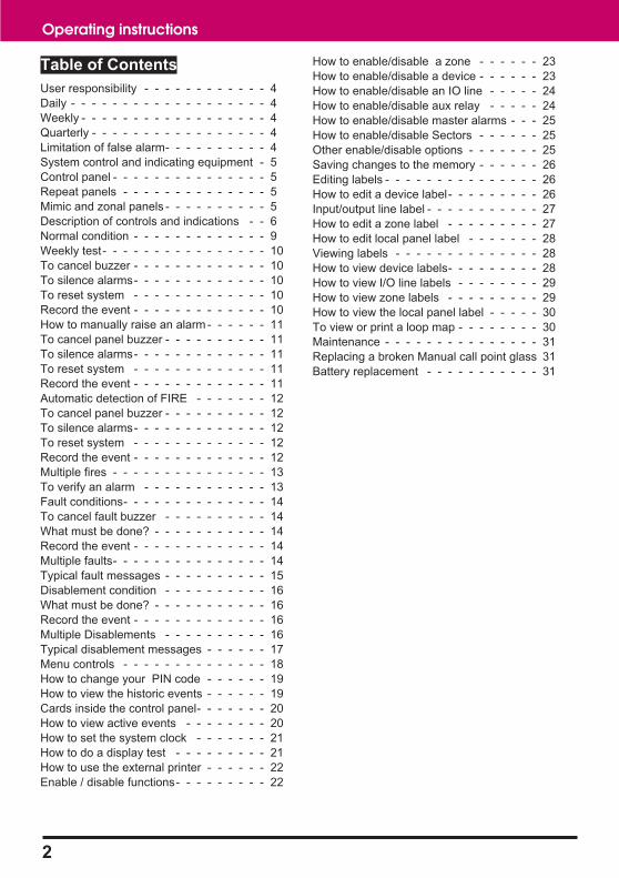
Table of Contents
User responsibility - - - - - - - - - - - - 4
Daily - - - - - - - - - - - - - - - - - - - 4
Weekly - - - - - - - - - - - - - - - - - - 4
Quarterly - - - - - - - - - - - - - - - - - 4
Limitation of false alarm- - - - - - - - - - 4
System control and indicating equipment - 5
Control panel - - - - - - - - - - - - - - - 5
Repeat panels - - - - - - - - - - - - - - 5
Mimic and zonal panels - - - - - - - - - - 5
Description of controls and indications - - 6
Normal condition - - - - - - - - - - - - - 9
Weekly test- - - - - - - - - - - - - - - - 10
To cancel buzzer - - - - - - - - - - - - - 10
To silence alarms- - - - - - - - - - - - - 10
To reset system - - - - - - - - - - - - - 10
Record the event - - - - - - - - - - - - - 10
How to manually raise an alarm - - - - - - 11
To cancel panel buzzer - - - - - - - - - - 11
To silence alarms- - - - - - - - - - - - - 11
To reset system - - - - - - - - - - - - - 11
Record the event - - - - - - - - - - - - - 11
Automatic detection of FIRE - - - - - - - 12
To cancel panel buzzer - - - - - - - - - - 12
To silence alarms- - - - - - - - - - - - - 12
To reset system - - - - - - - - - - - - - 12
Record the event - - - - - - - - - - - - - 12
Multiple fires - - - - - - - - - - - - - - - 13
To verify an alarm - - - - - - - - - - - - 13
Fault conditions- - - - - - - - - - - - - - 14
To cancel fault buzzer - - - - - - - - - - 14
What must be done? - - - - - - - - - - - 14
Record the event - - - - - - - - - - - - - 14
Multiple faults- - - - - - - - - - - - - - - 14
Typical fault messages - - - - - - - - - - 15
Disablement condition - - - - - - - - - - 16
What must be done? - - - - - - - - - - - 16
Record the event - - - - - - - - - - - - - 16
Multiple Disablements - - - - - - - - - - 16
Typical disablement messages - - - - - - 17
Menu controls - - - - - - - - - - - - - - 18
How to change your PIN code - - - - - - 19
How to view the historic events - - - - - - 19
Cards inside the control panel- - - - - - - 20
How to view active events - - - - - - - - 20
How to set the system clock - - - - - - - 21
How to do a display test - - - - - - - - - 21
How to use the external printer - - - - - - 22
Enable / disable functions- - - - - - - - - 22
How to enable/disable a zone - - - - - - 23
How to enable/disable a device - - - - - - 23
How to enable/disable an IO line - - - - - 24
How to enable/disable aux relay - - - - - 24
How to enable/disable master alarms - - - 25
How to enable/disable Sectors - - - - - - 25
Other enable/disable options - - - - - - - 25
Saving changes to the memory - - - - - - 26
Editing labels - - - - - - - - - - - - - - - 26
How to edit a device label- - - - - - - - - 26
Input/output line label - - - - - - - - - - - 27
How to edit a zone label - - - - - - - - - 27
How to edit local panel label - - - - - - - 28
Viewing labels - - - - - - - - - - - - - - 28
How to view device labels- - - - - - - - - 28
How to view I/O line labels - - - - - - - - 29
How to view zone labels - - - - - - - - - 29
How to view the local panel label - - - - - 30
To view or print a loop map - - - - - - - - 30
Maintenance - - - - - - - - - - - - - - - 31
Replacing a broken Manual call point glass 31
Battery replacement - - - - - - - - - - - 31
Preface
This first issue of the operating instructions is for the Vigilon Compact fire detection and alarms system.
Associated documents
Vigilon Compact Installation instructions
Vigilon Compact Log Book
Conventions
� This is a note to highlight important text that is normally hidden in the maintext.
� This is either a caution to prevent damage to the equipment or awarning to inform of dangerous conditions that may result in injury or death.
Symbol Keys
What you will see
What you willl hear
A fire condition
LED illuminated On
LED illuminated Flashing
The information in this manual is being supplied without liability for errors or omissions. No part of the manualmay be reproduced in any form whatsoever without prior consent of the company. Due to the ongoingdevelopment of products the information contained in this manual is subject to change without notice.
3
Vigilon COMPACT

User responsibility
Your fire alarm system should have been designed,installed and commissioned to your site specificrequirements and in accordance with therequirements of BS5839 Part 1. You should havereceived instructions about your system during thehandover stage and must make arrangement toensure the system is regularly tested and maintained.
It is recommended that the person responsible forthe fire alarm system should ensure the system istested and maintained in accordance with therequirements of BS5839 Part 1 and become familiarwith:
� how to operate the controls and interpretthe indications given at the control panel
� keep up to date all documentationassociated with the system.
� Any servicing work on theVigilon system must be carried out bya suitably trained person refer to yourservicing organisation.
DailyBS 5839:Part 1, states that the system should beinspected daily to ensure
� That a normal indication is given at thecontrol and indicating equipment.
� That any previously indicated fault
condition has received appropriateattention.
� All the system events are entered intothe Log Book for future reference.
� That the use of the area(s) inspected hasnot changed since the system wasdesigned.
� That no unsafe practices that could leadto fire are being undertaken.
WeeklyWhen testing the system there may be a need toisolate ancillary outputs and to contact the alarmreceiving centre before and after the weekly test.
� A different manual call point of thesystem should be tested to ensure thesystem is capable of operating underalarm conditions.
� The operation of the alarm sounders
should be checked to remind thoseoccupying the premises that there is afire alarm system with a particularsound.
� The test should be performedat a regular time to avoid confusionbetween a test and a genuine fire alarm.The alarm receiving centre must becontacted before and after the test tocheck alarms are received and also toavoid unwanted alarms.
QuarterlyAt quarterly intervals the system should be inspectedand any work necessary should be performed by atrained maintenance engineer.
� For help with service andmaintenance please refer to your servicingorganisation, see contact details enteredin the log book.
Limitation of false alarmIt is recommended that the person responsible for thefire alarm system should arrange for suitableinvestigation and appropriate action on occasion ofevery false alarm. For a system having less than 40automatic fire detectors installed, an in-depthinvestigation should be instigated on occurance of twofalse alarms in any rolling 12 months. For a systemhaving more than 40 automatic fire detectors aninvestigation shoud be instigated if there has been:
� one false alarm for every 20 detectorsinstalled in the system in any rolling 12months, or
� two or more false alarm occurance froma single device / outstation.
4
Operating instructions

System control and indicating equipment
The events of fire, fault and disablements are indicated at the control and indicating equipment installed in theprotected premises. The control and indicating equipment should be accessible to the person responsible forthe fire system.
Control panelThe control panel is the heart of the system. It is normally locatednear to the main entry / exit point of the protected premises.
The control panel continuously monitors devices that areconnected to each loop cable. The loop cable is routed throughthe protected premises to cover all areas with both ends of theloop terminating at the control panel.
Devices installed on the loop such as the fire sensors areconstantly sensing the environment for fire, whilst the alarmdevices provide alert and evacuations alarm to warn occupants inthe protected premises in the event of a fire.
Repeat panelsYour system may have repeat panels installed to providesecondary indications and controls for the system. They areusually located near to secondary entry / exit points of theprotected premises.
The larger repeat panel has a similar appearance to the maincontrol panel and provides both system indication and alarmcontrols. The smaller repeat panel provides only indications ofevents.
Mimic and zonal panelsThere may be a number of mimic and zonal panels installed inthe protected premises, to provide visual indications in agraphical or zonal format. Normally one is installed next to themain control panel. There may be additional panels installed inother areas of the protected premises. The smaller mimic or zonalpanels may be used to cover sub divisions of the premises, whilethe larger panel may cover the entire site.
Vigilon COMPACT
5
firepower fault
A4 Mimic PanelA4 Zonal Panel
A2 Mimic PanelA2 Zonal Panel

Description of controls and indications
Open the front door to reveal the controls
Operating instructions
6
Access level 2Controls
Indications
Operating instructionsand Log Book
MessageDisplay
Access level 1Controlsto scroll events
Key lockto openthe outer door
Outer door
Inner door
Previous Next
Fault
System Fault
Power Fault
Sounder
Fire
Power
ABC DEF
GHI JKL MNO
Vigilon Compact Fire System
Cancel BuzzerMenu On/Off
Verify
1 2 3
4 5 6PQRS TUV WXYZ
7 8 9
0
Sound Alarms
Silence Alarms
Reset
Enter
THRU BKSP
0INS DEL
F1 F2 F3 F4
Disablement Verify
U1
U2
Panel healthy 15:45
CB253
CB254
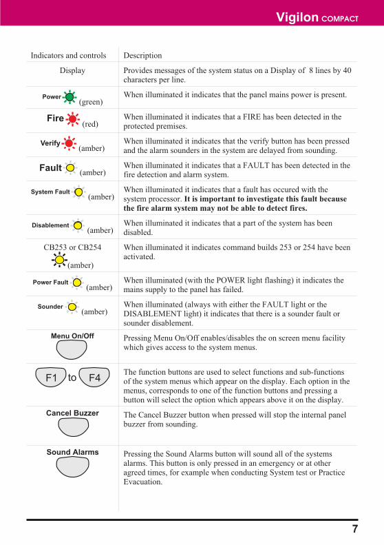
Indicators and controls Description
Display Provides messages of the system status on a Display of 8 lines by 40characters per line.
(green)When illuminated it indicates that the panel mains power is present.
(red)When illuminated it indicates that a FIRE has been detected in theprotected premises.
(amber)When illuminated it indicates that the verify button has been pressedand the alarm sounders in the system are delayed from sounding.
(amber)When illuminated it indicates that a FAULT has been detected in thefire detection and alarm system.
(amber)When illuminated it indicates that a fault has occured with thesystem processor. It is important to investigate this fault because
the fire alarm system may not be able to detect fires.
(amber)When illuminated it indicates that a part of the system has beendisabled.
CB253 or CB254
(amber)
When illuminated it indicates command builds 253 or 254 have beenactivated.
(amber)When illuminated (with the POWER light flashing) it indicates themains supply to the panel has failed.
(amber)When illuminated (always with either the FAULT light or theDISABLEMENT light) it indicates that there is a sounder fault orsounder disablement.
Pressing Menu On/Off enables/disables the on screen menu facilitywhich gives access to the system menus.
The function buttons are used to select functions and sub-functionsof the system menus which appear on the display. Each option in themenus, corresponds to one of the function buttons and pressing abutton will select the option which appears above it on the display.
The Cancel Buzzer button when pressed will stop the internal panelbuzzer from sounding.
Pressing the Sound Alarms button will sound all of the systemsalarms. This button is only pressed in an emergency or at otheragreed times, for example when conducting System test or PracticeEvacuation.
Vigilon COMPACT
7
Power
Fire
Fault
System Fault
Disablement
Power Fault
Sounder
Menu On/Off
F1 F4to
Next
Cancel Buzzer
Verify
Sound Alarms
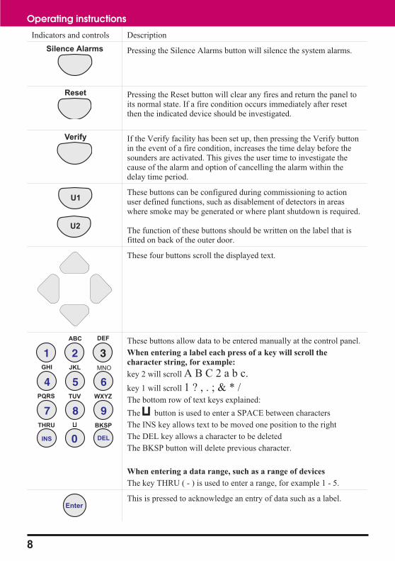
Indicators and controls Description
Pressing the Silence Alarms button will silence the system alarms.
Pressing the Reset button will clear any fires and return the panel toits normal state. If a fire condition occurs immediately after resetthen the indicated device should be investigated.
If the Verify facility has been set up, then pressing the Verify buttonin the event of a fire condition, increases the time delay before thesounders are activated. This gives the user time to investigate thecause of the alarm and option of cancelling the alarm within thedelay time period.
These buttons can be configured during commissioning to actionuser defined functions, such as disablement of detectors in areaswhere smoke may be generated or where plant shutdown is required.
The function of these buttons should be written on the label that isfitted on back of the outer door.
These four buttons scroll the displayed text.
These buttons allow data to be entered manually at the control panel.
When entering a label each press of a key will scroll the
character string, for example:
key 2 will scroll A B C 2 a b c.
key 1 will scroll 1 ? , . ; & * /The bottom row of text keys explained:
The button is used to enter a SPACE between characters
The INS key allows text to be moved one position to the right
The DEL key allows a character to be deleted
The BKSP button will delete previous character.
When entering a data range, such as a range of devices
The key THRU ( - ) is used to enter a range, for example 1 - 5.
This is pressed to acknowledge an entry of data such as a label.
8
Operating instructions
Verify
U1
U2
Reset
ABC DEF
GHI JKL MNO
1 2 3
4 5 6PQRS TUV WXYZ
7 8 9
0THRU BKSP
0INS DEL
Silence Alarms
Enter

Normal condition
A system operating normally is indicated at the panel by the:
� Power indicator being illuminated
� the display showing a Panel healthy message.
9
Vigilon COMPACT
Fault
System Fault
Power Fault
Sounder
Fire
Power
Disablement Verify
Vigilon Compact Fire System
Panel healthy 15:45
On
Flashing
CB254
CB253

Weekly test
Every week during normal working hours the fire detection and alarm system should be tested. It is importantto inform the alarm receiving centre of the fire test.
The weekly fire test can be carried out at a manual call point without breaking the call point glass. Insert thetest key through the hole in the underside of the call point to engage the cam mechanism and push to operatethe cam mechanism. This will activate the call point.
At this point the test key is retained in the call point and pulling it out will reset the call point.
� Check the alarms are sounding in the building and an indication is given of the fireevent.
� Remove the test key from the call point, open the panel door to silence the alarms andreset the system.
To cancel buzzer You can stop the panel buzzerfrom sounding.
Press:
Display reads: 'Buzzer cancelled'
To silence alarms When the test is complete thealarm sounders can be silenced.
Press:
Display reads: 'Alarms silenced'‘
To reset system To return the system to normalcondition clear any residualsmoke or heat from detectorsand replace the glass in anymanual call points where theglass was broken.
Press:
Display reads 'System being Reset -please wait....'
Record the event Make an entry in the log bookof the event for future reference.
10
Operating instructions
FIREPRESS HARD TO
BREAK GLASS
Test key
Manual Call point
Fault
System Fault
Power Fault
Sounder
Fire
Power
Disablement Verify
First Fire occurred at:
Time: 08:43.10 Thu 12 September 2002
1stFIRE:MCP:Zone 1 15:45
Panelbuzzer
On
Flashing
CB253
CB254
Cancel Buzzer
Silence Alarms
Reset
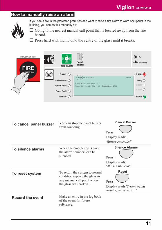
How to manually raise an alarm
If you see a fire in the protected premises and want to raise a fire alarm to warn occupants in thebuilding, you can do this manually by:
� Going to the nearest manual call point that is located away from the firehazard.
� Press hard with thumb onto the centre of the glass until it breaks.
To cancel panel buzzer You can stop the panel buzzerfrom sounding.
Press:
Display reads:
'Buzzer cancelled'
To silence alarms When the emergency is overthe alarm sounders can besilenced. Press:
Display reads:'Alarms silenced'‘
To reset system To return the system to normalcondition replace the glass inany manual call point wherethe glass was broken.
Press:
Display reads 'System beingReset - please wait....'
Record the event Make an entry in the log bookof the event for futurereference.
11
Vigilon COMPACT
FIREPRESS HARD TO
BREAK GLASS
Manual Call point
Fault
System Fault
Power Fault
Sounder
Fire
Power
Disablement Verify
First Fire occurred at:
Time: 08:43.10 Thu 12 September 2002
1stFIRE:MCP:Zone 1 15:45
Panelbuzzer
On
Flashing
CB253
CB254
Cancel Buzzer
Silence Alarms
Reset

Automatic detection of FIRE
A fire in your protected premises is automatically sensed at any one of the fire detection devicesinstalled in the building, such as a sensor or a fire input from an interface. The control panelactions the alarm sounders in the system and at the same time gives the details of the fire event.The event indication is repeated at all repeat, zonal and mimic panels in the system.
To cancel panel buzzer You can stop the panel buzzerfrom sounding.
Press:
Display reads:
'Buzzer cancelled'
To silence alarms When the emergency is overthe alarm sounders can besilenced. Press:
Display reads:'Alarms silenced'
To reset system To return the system to normalcondition clear any residualsmoke or heat from detectorsand reset any fire inputs.
Have the system checked by
your servicing organisation
if there has been fire damage
in the protected area.
Press:
Display reads 'System beingReset - please wait....'
Record the event Make an entry in the log bookof the event for futurereference.
12
Operating instructions
Fault
System Fault
Power Fault
Sounder
Fire
Power
Disablement Verify
First Fire occurred at:
Time: 08:43.10 Thu 12 September 2002
1stFIRE:Zone 1 15:45
Panelbuzzer
On
Flashing
CB253
CB254
Cancel Buzzer
Silence Alarms
Reset
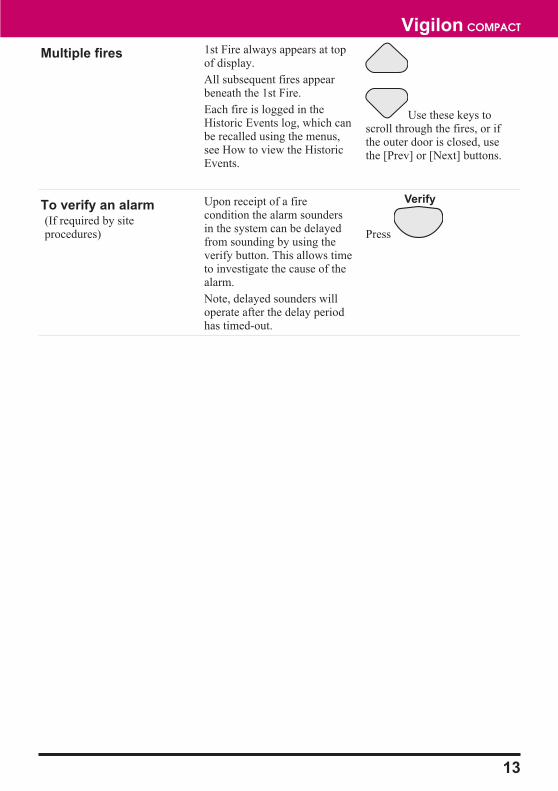
Multiple fires 1st Fire always appears at topof display.
All subsequent fires appearbeneath the 1st Fire.
Each fire is logged in theHistoric Events log, which canbe recalled using the menus,see How to view the HistoricEvents.
Use these keys toscroll through the fires, or ifthe outer door is closed, usethe [Prev] or [Next] buttons.
To verify an alarm(If required by siteprocedures)
Upon receipt of a firecondition the alarm soundersin the system can be delayedfrom sounding by using theverify button. This allows timeto investigate the cause of thealarm.
Note, delayed sounders willoperate after the delay periodhas timed-out.
Press
13
Vigilon COMPACT
Verify
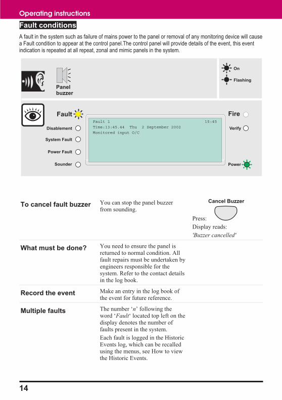
Fault conditions
A fault in the system such as failure of mains power to the panel or removal of any monitoring device will causea Fault condition to appear at the control panel.The control panel will provide details of the event, this eventindication is repeated at all repeat, zonal and mimic panels in the system.
To cancel fault buzzer You can stop the panel buzzerfrom sounding.
Press:
Display reads:
'Buzzer cancelled'
What must be done? You need to ensure the panel isreturned to normal condition. Allfault repairs must be undertaken byengineers responsible for thesystem. Refer to the contact detailsin the log book.
Record the event Make an entry in the log book ofthe event for future reference.
Multiple faults The number ‘n’ following theword ‘Fault‘ located top left on thedisplay denotes the number offaults present in the system.
Each fault is logged in the HistoricEvents log, which can be recalledusing the menus, see How to viewthe Historic Events.
14
Operating instructions
Fault
System Fault
Power Fault
Sounder
Fire
Power
Disablement Verify
Fault 1
Time:13:45.44 Thu 2 September 2002
Monitored input O/C
15:45
Panelbuzzer
On
Flashing
Cancel Buzzer
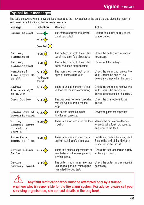
Typical fault messages
The table below shows some typical fault messages that may appear at the panel. It also gives the meaningand possible rectification action for each message.
Message Indication Meaning Action
Mains failed The mains supply to the controlpanel has failed.
Restore the mains supply to thecontrol panel.
Batterydischarged
The battery supply to the controlpanel has been fully discharged.
Check the battery and replace ifnecessary.
Batterydisconnected
The battery supply to the controlpanel has been disconnected.
Reconnect the battery.
Monitoredline input OSor SC (no buzzer
sound)
The monitored line input has anopen or short circuit fault.
Check the wiring and remove thefault. Ensure the end-of-linedevice is connected in the circuit.
MasterAlarm(s) O/Cor S/C n
There is an open or short circuitfault on the master alarm wiring.
Check the wiring and remove thefault. Ensure the end-of-linedevice is connected in the circuit.
Lost Device The Device is not communicatingwith the Control Panel via theloop.
Check the connections to thedevice.
Sensor out ofspecification
The device indicated is notfunctioning correctly.
Device requires maintenance.
Wiringchanged shortcircuit atcard n
There is a short circuit on the loopn wiring.
Identify the outstation (device)where a cable fault has occurredand remove the fault.
Interfaceinput os / sc
There is an open or short circuiton the input line of an interface
Locate and rectify the wiring fault.Ensure the end-of-line device isconnected in the circuit.
Device Mainsfailed
There is a mains supply failure atan interface unit, repeat panel ora mimic panel.
Check the fuse and mains supplyto the equipment.
DeviceBattery fault
The battery supply at an interfaceunit, repeat panel or mimic panelhas failed the load test.
Check the battery and replace it ifnecessary.
� Any fault rectification work must be attempted only by a trainedengineer who is responsible for the fire alarm system. For advice, please call yourservicing organisation, see contact details in the Log book.
15
Vigilon COMPACT
Fault
Power fault
Fault
Fault
Fault
Fault
Fault
Fault
Fault
Fault
Fault
Fault
Power

Disablement condition
A disablement condition is the manual or automatic disablement of a part of the fire detection and alarmsystem. An automatic disablement may be preconfigured for your premises to disable smoke sensors duringthe normal working hours in areas where smoking is allowed. A manual disablement may be necessary wherebuilding work is being undertaken that can result in a false alarm.
What must be done? Investigate the reason for thedisablement and re-instate thedevices if appropriate.
Record the event Where necessary make anentry in the log book of theevent for future reference.
Multiple Disablements The number ‘n’ following theword ‘Disable‘ located top lefton the display denotes thenumber of disablementspresent in the system.
Each disablement is logged inthe Historic Events log whichcan be recalled, using themenus, see How to view theHistoric Events.
16
Operating instructions
Fault
System Fault
Power Fault
Sounder
Fire
Power
Disablement Verify
Time:13:45.44 Thu 2 September 2002
Outstation Disabled at card 1
13:45
On
Flashing
Only given if a sounder device in the system is disabled
CB253
CB254

Typical disablement messagesThe following table shows some typical disablement messages that may appear at the panel.
Message Indication Meaning Action
Zone Disabledat Card n
The zone specified has beenmanually or automaticallydisabled.
If manually disabled theninvestigate and if necessaryre-enable the zone.
Outstationdisabled atcard n
The device connected to theloop circuit has been manuallyor automatically disabled.
If manually disabled theninvestigate and, if appropriate,re-enable the device.
Sectordisabled atcard n
The fire alarm sector on loop nhas been manually orautomatically disabled.
If manually disabled theninvestigate and, if appropriate,re-enable the sector.
Aux Relay nDisabled
The auxiliary relay n in thecontrol panel has beenmanually or automaticallydisabled.
If manually disabled theninvestigate and, if appropriate,re-enable the aux relay.
Master alarmsdisabled
The master alarms have beenmanually or automaticallydisabled.
If manually disabled theninvestigate and, if appropriate,re-enable the master alarms.
� Any changes to the setting of an automatic disablement may only beattempted by a trained engineer who is responsible for the fire alarm system, seecontact details in the Log book.
17
Vigilon COMPACT
Disablement
Disablement
Disablement
Disablement
Disablement
Sounder
Sounder

Menu controls
The MENU ON/OFF button facilitates the operation of the function keys F1 to F4. The menu prompts appearabove the function keys on the display, to prompt the user to make a selection.
At any level in a menu, successive pressing of the MENU ON/OFF key, aborts an operation. However as analternative, the [Quit] prompt can be selected to exit the function mode.
If the time taken between key presses exceeds one minute, the control panel will automatically remove theprompt display and give system status indications.
The [Params] prompt is a Help function to provide information to the user regarding the type of input datarequired.
Most of the functions in the [Control], [Setup] and [TestEng] menus, are protected with password entry. ThePIN code is programmed during commissioning of the system and is passed on to the site person responsiblefor the fire alarm system.
� Open access to controls under usercode is undesirable. It isrecommended that customer password (PIN code) is setup.
When a PIN code is not set up, there is an open entry to operate the controls under [User Code]. Where this istrue the instructions for entering the access code (or PIN) in the following instructions should be ignored.
18
Operating instructions
Panel beepson button press
On
Flashing
Previous Next
Fault
System Fault
Power Fault
Sounder
Fire
Power
Vigilon Compact Fire System
GENT 2002
Cancel BuzzerMenu On/Off
F1 F2 F3 F4
Disablement Verify
15:45
[Control] [ Set Up ] [ Info ] [ Test/Eng]
CB253
CB254

How to change your PIN code
A user PIN code is normally set up by the servicingorganisation during commissioning of the fire alarmsystem. The PIN code (password) that is set up is forthe end user. The person responsible for the firealarm system should be aware of this PIN code. Forsecurity the PIN should be changed on a regularbasis. A previously created PIN can be changed by:
a. Press the MENU ON/OFF button.
b. Press the F4 button to select [Test/Eng].
c. Press the F4 button to select [UserCode]. Usethe keypad to input your existing access code
and then press the Enter button.
d. Press the F4 key to select <etc>, repeat until[NewPass] is displayed above F1.
e. Press the F1 button to select [New Pass].Notice a message on the display ‘Enter newaccess code’ with a flashing cursor above it.Use the keypad to input a PIN code and thenpress the Enter button. Notice ‘New accesscode set up’ appears on the display.
� Changes to the PIN code at theControl panel must be backed-up to theMemory. If this is not done then theprevious PIN is restored on resetting thepanel, see saving changes to the memory.
How to view the historic events
Up to 255 events are stored in the Historic log of thepanel. To view the Historic log.
a. Press MENU ON/OFF.
b. Press the F3 button to select [Info].
� You can skip the next step if aprinter is not connected to the panel.
c. To display the event(s): Press the F1 button toselect [Display]. Notice ‘Display’ appears onthe display.To print the event(s): Press the F2 button toselect [Print] Notice ‘Print’ appears on thedisplay.
d. Press the F2 button to select [Historic]. Notice‘Historic’ followed by a flashing cursor appearson the display.
e. Use the keypad to input an event number orrange (1-255).
� Event '1' is always the mostrecent event.
f. Press the F2 button to select [Enter]. Notice allthe active Fire, Fault and Disablement eventswill be displayed or printed depending on yourselection.
19
Vigilon COMPACT
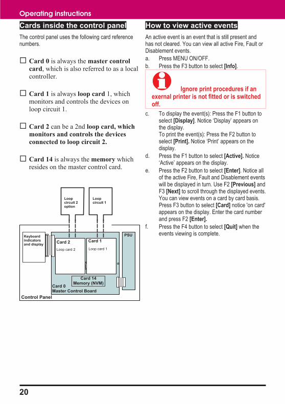
Cards inside the control panel
The control panel uses the following card referencenumbers.
� Card 0 is always the master control
card, which is also referred to as a localcontroller.
� Card 1 is always loop card 1, whichmonitors and controls the devices onloop circuit 1.
� Card 2 can be a 2nd loop card, which
monitors and controls the devices
connected to loop circuit 2.
� Card 14 is always the memory whichresides on the master control card.
How to view active events
An active event is an event that is still present andhas not cleared. You can view all active Fire, Fault orDisablement events.
a. Press MENU ON/OFF.
b. Press the F3 button to select [Info].
� Ignore print procedures if anexernal printer is not fitted or is switchedoff.
c. To display the event(s): Press the F1 button toselect [Display]. Notice ‘Display’ appears onthe display.To print the event(s): Press the F2 button toselect [Print]. Notice ‘Print’ appears on thedisplay.
d. Press the F1 button to select [Active]. Notice‘Active’ appears on the display.
e. Press the F2 button to select [Enter]. Notice allof the active Fire, Fault and Disablement eventswill be displayed in turn. Use F2 [Previous] andF3 [Next] to scroll through the displayed events.You can view events on a card by card basis.Press F3 button to select [Card] notice 'on card'appears on the display. Enter the card numberand press F2 [Enter].
f. Press the F4 button to select [Quit] when theevents viewing is complete.
20
Operating instructions
CODE BACKUP
Loop Card
Card 0Master Control Board
Keyboardindicatorsand display
PSU
Loop card 1Loop card 2
Card 1Card 2
Loopcircuit 1
Loopcircuit 2option
Card 14Memory (NVM)
Control Panel

How to set the system clock
� An incorrect setting of thesystem clock will affect the timerelated sensor configuration and alsoresults in incorrect event timeinformation
a. Press the MENU ON/OFF key and then the F2key to select [Set Up].
b. Press the F4 key to select [User Code]. Checkthat User Code followed by a flashing cursorappears on the screen. Key in the PIN code andpress the Enter button.
c. Press the F1 key to select [Set Clock]. Thesystem clock is displayed on the screen. Checkthat the hour digits are flashing.
d. Press the F2 or F3 key to [Retard] or[Advance] to the desired setting.
e. Press the F1 key to select [Next]. Check thatthe Minute digits are now flashing.
f. Press the F2 or F3 key to [Retard] or[Advance] to the desired setting.
g. Press the F1 key to select [Next]. Check thatthe Date digits are now flashing.
h. Press the F2 or F3 key to [Retard] or[Advance] to the desired setting.
i. Press the F1 key to select [Next]. Check thatthe Month is now flashing.
j. Press the F2 or F3 key to [Retard] or[Advance] to the desired setting.
k. Press the F1 key to select [Next]. Check thatthe Year is now flashing.
l. Press the F2 or F3 key to [Retard] or[Advance] to the desired setting.
m. Press the F4 key to select [Enter]. Check thatthe display now shows the new time and date.
� Changes made to time and datehere will be automatically updated at therepeat panels installed in the system.This system does not automaticallyupdate clock for daylight saving changes.
How to do a display test
You can test the message display and the indicatorson the control panel.
a. Press the MENU ON/OFF key and then the F4key to select [Test/Eng].
b. Press the F1 key to select [Disp Test]. Checkthat the following things happen: The red,green, and amber lights are illuminated forapproximately two seconds. The display iscleared for approximately two seconds and thendisplays a system status message. The buzzersounds for approximately two seconds.
21
Vigilon COMPACT

How to use the external printer
These functions are only applicable if your panel hasa printer connected.
To Switch On the Printer
a. Press the MENU ON/OFF key.
b. Press the F1 key to select [Control].
c. Press the F3 key to select [Printer]. Check that‘Printer’ appears on the screen.
d. Press the F3 key to select [On] and then pressthe F2 key to select [Enter]. Check that themessage ‘Printer is on’ appears on the displayto show that the action has been successfullycarried out. Check that the printer provides alisting of this event.
To action an Automatic Paper Feed
a. Press the MENU ON/OFF key.
b. Press the F1 key to select [Control].
c. Press the F3 key to select [Printer]. Check that‘Printer’ appears on the screen.
d. Press the F2 key to select [Paper Fd].
e. Check that the displayed messages and themenu prompts are cleared.
f. Check that the printer performs eight line feeds.
To conduct a Printer Test
a. Press the MENU ON/OFF key.
b. Press the F1 key to select [Control].
c. Press the F3 key to select [Printer]. Check that‘Printer’ appears on the screen.
d. Press the F1 key to select [Test].
e. Check that the displayed messages and themenu prompts are cleared.
f. Check that the printer provides a listing of all thecharacters it is capable of printing.
To Switch Off the Printer
a. Press the MENU ON/OFF key.
b. Press the F1 key to select [Control].
c. Press the F3 key to select [Printer]. Check that‘Printer’ appears on the screen.
d. Press the F3 key to select [Off]
e. Press the F2 key to select [Enter].
f. Check that the message ‘Printer is off’ appearson the display to show that the action has beensuccessfully carried out.
Enable / disable functions
� Disabling an extinguishantinterface device / outstation does notdisable the outstation outputs. Hencethe extinguishant agent could bereleased. However, the disabling ofthe appropriate sectors would preventoutputs operating on fire. Sectorsreserved for extinguishantapplications can be manually operatedusing the control menu, for advicecontact the servicing organisation,for details see the log book.
� It is only possible to disable aManual Call Point (MCP) individually, notas part of a range. Disabling an MCP ishowever, not recommended.
22
Operating instructions
How to enable/disable a zone
A zone is a subdivision of your premises protected bythe fire alarm system. There can be up to 128 zonesconfigured in a system. Any zone operation can bedisabled or enabled. You will need the zone numberand loop number, this you can find in the site specificdocumentation, held by the person responsible for thefire alarm system.
� Disabling a zone does notdisable manual call points in the zone.Therefore, a fire alarm can be raised byoperating a call point in a disabled zone.
a. Press the MENU ON/OFF key.
b. Press the F1 button to select [Control].
c. Press the F4 button to select [UserCode].Notice a flashing cursor and a message on thedisplay ‘Enter access code’. Use the keypad toinput your PIN code and then press the Enter
button.
d. To disable: Press the F2 button to select[Disable]. This puts ‘Disable’ on the display.To enable: Press the F1 button to select[Enable]. This puts ‘Enable’ on the display.
e. Press the F4 button to select <etc> and thenpress the F2 button to select [Zone]. Notice‘Zone’ appears on the display followed by aflashing cursor. Use the keypad to input a zonenumber or range (1-128).
f. Press the F2 button to select [Enter]. Notice theaction has been processed and a messageappears on the display ‘Zone n enabled ordisabled’. The Disablement light will beilluminate upon disablement of any a zone.
How to enable/disable a device
A device can be any system equipment that isconnected to the loop circuit of the system. There canbe up to 200 devices per loop. Any device operationcan be disabled and re enabled. You will need thedevice number and loop number, this you can find inthe site specific documentation, held by the personresponsible for the fire alarm system.
a. Press the MENU ON/OFF key.
b. Press the F1 button to select [Control].
c. Press the F4 button to select [UserCode].Notice a flashing cursor and a message on thedisplay ‘Enter access code’. Use the keypad toinput your PIN code and then press the Enter
button.
d. To disable: Press the F2 button to select[Disable]. This puts ‘Disable’ on the display.To enable:Press the F1 button to select[Enable]. This puts ‘Enable’ on the display.
e. Press the F1 button to select [Device]. Notice‘Device’ followed by a flashing cursor appearson the display. Use the keypad to input an
outstation number or range (1-200).
f. Press the F2 button to select [Loop]. Notice‘Loop’ followed by a flashing cursor on thedisplay. Use the keypad to input a loop number
or range (1-2).
g. Press the F2 button to select [Enter]. Notice theaction has been processed and confirmed by amessage either: ‘Device(s) enabled’ or‘Device(s) disabled’. Notice that theDisablement light is illuminate upon disablementof any system device.
23
Vigilon COMPACT
How to enable/disable an IO line
An IO line is an input or output line of an interface.There can be up to four input/output lines on aninterface unit, which can be disabled or enabled. Youwill need the IO line number, device number and loopnumber, this you can find in the site specificdocumentation, held by the person responsible for thefire alarm system.
� An output line of aninterface unit is normally assigned toa sector. The output line can only bedisabled by disabling that sector,which has the effect of also disablingall other devices in thesector.
a. Press the MENU ON/OFF key.
b. Press the F1 button to select [Control].
c. Press the F4 button to select [UserCode].Notice a flashing cursor and a message on thedisplay ‘Enter access code’. Use the keypad toinput your PIN code and then press the Enter
button.
d. To disable: Press the F2 button to select[Disable]. This puts ‘Disable’ on the display.To enable: Press the F1 button to select[Enable]. This puts ‘Enable’ on the display.
e. Press the F2 button to select [IO Line]. Notice‘IO Line’ followed by a flashing cursor appearson the display. Use the keypad to input IO line
number or range (1-4).
f. Press the F2 button to select [Device]. Notice‘Device’ followed by a flashing cursor appearson the display. Use the keypad to input an
outstation number or range (1-200).
g. Press the F2 button to select [Loop]. Notice‘Loop’ followed by a flashing cursor on thedisplay. Use the keypad to input a loop number
or range (1-2).
h. Press the F2 button to select [Enter]. Notice theaction has been processed and a messageappears on the display ‘IO line disabled/enabledat Card n’. The disablement light will illuminateupon disablement of an IO line.
How to enable/disable aux relay
The control panel has two auxiliary relays that providevoltage free contacts to control external equipment inthe event of a fire or fault in the system. The operationof the relays can be disabled or enabled.
a. Press the MENU ON/OFF key.
b. Press the F1 button to select [Control].
c. Press the F4 button to select [UserCode].Notice a flashing cursor and a message on thedisplay ‘Enter access code’. Use the keypad toinput your PIN code and then press the Enter
button.
d. To disable:Press the F2 button to select[Disable]. This puts ‘Disable’ on the display.To enable:Press the F1 button to select[Enable]. This puts ‘Enable’ on the display.
e. Press the F4 button twice to select <etc> andthen press the F2 button to select [Aux Rly].Notice ‘Aux Rly’ followed by a flashing cursorappears on the display. Use the keypad to input
an auxiliary relay number or range (1-2).
f. Press the F2 button to select [Enter]. Notice theaction has been processed and a messageappears on the display ‘Aux Rly ndisabled/enabled’. The Disablement light willilluminate upon disablement of an auxiliaryrelay.
24
Operating instructions
How to enable/disable
master alarms
The control panel allows the connection of up to twocircuits of master alarms, these are conventionalalarm sounders. The master alarms can be disabledor enabled.
a. Press the MENU ON/OFF key.
b. Press the F1 button to select [Control].
c. Press the F4 button to select [UserCode].Notice a flashing cursor and a message on thedisplay ‘Enter access code’. Use the keypad toinput your PIN code and then press the Enterbutton.
d. To disable:Press the F2 button to select[Disable]. This puts ‘Disable’ on the display.To enable:Press the F1 button to select[Enable]. This puts ‘Enable’ on the display.
e. Press the F4 button twice to select <etc> andthen press the F1 button to select [MAlarm].Notice ‘Master Alarms’ appears on the display.
f. Press the F2 button to select [Enter]. Notice theaction has been processed and a messageappears on the display ‘Master sounderdisabled/enabled’. The Disablement light willilluminate upon disablement of master alarms.
How to enable/disable Sectors
The system can have up to 32 sectors per loopconfigured. Each sector is a subdivision of thepremises for the perpose of sounding alarms. To findthe sector you need to disable refer to the to sitespecific documentation, normally kept by the personresponsible for the fire alarm system.
a. Press the MENU ON/OFF key.
b. Press the F1 button to select [Control].
c. Press the F4 button to select [UserCode].Notice a flashing cursor and a message on thedisplay ‘Enter access code’. Use the keypad toinput your PIN code and then press the Enter
button.
d. To disable:Press the F2 button to select[Disable]. This puts ‘Disable’ on the display.To enable:Press the F1 button to select[Enable]. This puts ‘Enable’ on the display.
e. Press the F3 button to select [Sector]. Notice‘Sector’ appears on the display followed by aflashing cursor. Use the keypad to input asector number or range (1-32).
f. Press the F2 button to select [Loop]. Notice‘Loop’ followed by a flashing cursor on thedisplay. Use the keypad to input a loop numberor range (1-2).
g. Press the F2 button to select [Enter]. Notice theaction has been processed and a messageappears on the display ‘Sector disablement atCard n’. The Disablement light will be lit upondisablement of any sector and also the sounderlight illuminates.
Other enable/disable options
There are many other functions that are accessible forenablement and disablement. Functions likeCommand Build, Group, Master Sector andCommunication are normally not accessed, for furtheradvice contact your servicing organisation, see thecontact details in the Log book.
25
Vigilon COMPACT

Saving changes to the memory
If you make any changes to Labels or Password thenyou must save these to the NVM (Non VolatileMemory) or Memory of the panel.
� Data can only be saved to theMemory when there are no disablementspresent on the system.
The following procedures assume a customerpassword (PIN) is setup by the servicing organisation.
a. Press the MENU ON/OFF button.
b. Press the F2 button to select [Set Up].
c. Press the F4 button to select [UserCode].Notice a message on the display ‘Enter accesscode’ followed by a flashing cursor. Use thekeypad to input your PIN code and then pressthe Enter button.
d. Press the F3 button to select [Save].
e. Press the F2 button to select [Enter]. Observeconfirmation; data is backed up.
Editing labels
� Changes to labels must bebacked up to the Memory, see the sectionSaving changes to the memory.
How to edit a device label
A device is also referred to as an outstation. Therecan by up to 200 devices connected to a loop, deviceslike fire sensors, manual call points, interface units,repeat panels or alarm sounders. Each device can begiven a label to identify its location in the system.Devices in your system may have already been givenlabels and these labels can be changed. To edit adevice label you will need to know the device numberand the loop on which it resides. You can find thisinformation in the site specific documentation, held bythe person responsible for the fire alarm system.
a. Press the MENU ON/OFF button
b. Press the F2 button to select [Set Up].
c. Press the F4 button to select [UserCode].Notice a message on the display ‘Enter accesscode’, followed by a flashing cursor. Use thekeypad to input your PIN and then press Enterbutton.
d. Press the F4 button once to select <etc>
e. Press the F1 button to select [Modify]. Notice‘Modify’ appears on the display.
f. Press the F1 button to select [Label]. Notice‘Label’ appears on the display.
g. Press the F3 button to select [Device].Notice‘Device’ followed by a flashing cursor appearson the display.
h. Use the keypad to input a Device number.
i. Press the F2 button to select [Loop]. Notice‘Loop’ followed by a flashing cursor on thedisplay. Use the keypad to input a loop number[1-2].
j. Press the F2 button to select [Enter]. Notice theprevious label appears on the display with aflashing first character to prompt themodification, if there is no label the line is blank.
k. Using the keypad enter a label of up to 32characters in length and press the Enter button.
26
Operating instructions

Input/output line label
Each input / output (IO) line of an interface unit can begiven a label and a previously entered label can bemodified. To edit an IO line label you will need toknow the IO line number, interface device number andthe loop number it is connected to. You can find thisinformation in the site specific documentation, held bythe person responsible for the fire alarm system.
a. Press the MENU ON/OFF button.
b. Press the F2 button to select [Set Up].
c. Press the F4 button to select [UserCode].Notice a message on the display ‘Enter accesscode’, followed by a flashing cursor. Use thekeypad to input your PIN and then press Enterbutton.
d. Press the F4 button once to select <etc>
e. Press the F1 button to select [Modify]. Notice‘Modify’ appears on the display.
f. Press the F1 button to select [Label]. Notice‘Label’ appears on the display.
g. Press the F2 button to select [IO Line]. Notice‘IO Line’ followed by a flashing cursor on thedisplay. Using the keypad enter an input/outputnumber or range (1-4).
h. Press the F3 button to select [Device]. Notice‘Device’ followed by a flashing cursor appearson the display. Use the keypad to input aDevice number from the range 1-200.
i. Press the F2 button to select [Loop]. Notice‘Loop’ followed by a flashing cursor on thedisplay. Use the keypad to input a loop numberor range (1-2).
j. Press the F2 button to select [Enter]. Notice theprevious label appears on the display with aflashing first character to prompt themodification, if there is no label the line is blank.
k. Using the keypad enter a label of up to 32characters in length and press the Enter button.
How to edit a zone label
Each zone can be given a label and an entered labelcan be modified. To edit a zone label you will need toknow the zone number and the loop number. You canfind this information in the site specific documentation,held by the person responsible for the fire alarmsystem.
a. Press the MENU ON/OFF button.
b. Press the F2 button to select [Set Up].
c. Press the F4 button to select [UserCode].Notice a message on the display ‘Enter accesscode’, followed by a flashing cursor. Use thekeypad to input your PIN and then press Enterbutton.
d. Press the F4 button once to select <etc>
e. Press the F1 button to select [Modify]. Notice‘Modify’ appears on the display.
f. Press the F1 button to select [Label]. Notice‘Label’ appears on the display.
g. Press the F4 button once to select <etc>.
h. Press the F1 button to select [Zone]. Notice‘Zone’ followed by a flashing cursor appears onthe display. Using the keypad enter a number orrange (1-128).
i. Press the F2 button to select [Enter]. Notice theprevious label appears on the display with aflashing first character to prompt themodification, if there is no label the line is blank.
j. Using the keypad enter a label of up to32 characters in length and press the Enterbutton.
27
Vigilon COMPACT
How to edit local panel label
A label is normally given to the control panel toidentify its location in a network of control panels. Apreviously entered label can be modified.
a. Press the MENU ON/OFF button.
b. Press the F2 button to select [Set Up].
c. Press the F4 button to select [UserCode].Notice a message on the display ‘Enter accesscode’, followed by a flashing cursor. Use thekeypad to input the PIN and then press Enterbutton.
d. Press the F4 button once to select <etc>.
e. Press the F1 button to select [Modify]. Notice‘Modify’ appears on the display.
f. Press the F1 button to select [Label]. Notice‘Label’ appears on the display.
g. Press the F4 button once to select <etc>.
h. Press the F2 button to select [Local]. Notice‘local’ appears on the display.
i. Press the F2 button to select [Enter]. Notice theprevious label appears on the display with aflashing first character to prompt themodification, if there is no label the line is blank.
j. Using the keypad enter a label of up to40 characters in length and press the Enterbutton.
Viewing labels
The identification label given to each system devicecan be checked. Devices such as fire sensors, alarmsounders, manual call points, repeat panels, interfaceunits - including input/output lines, groups and thelocal panel label. The label information can either bedisplayed or printed.
How to view device labels
Each device is given a location label at the time thesystem is commissioned to identify its location. Toview a device label you will need to know the deviceaddress and the loop on which it resides. You can findthis information in the site specific documentation,held by the person responsible for the fire alarmsystem.
� Ignore print procedures if anexernal printer is not fitted or is switchedoff.
a. Press the MENU ON/OFF button.
b. Press the F3 button to select [Info].
c. To display a Device label: Press the F1 buttonto select [Display]. Notice ‘Display’ appears onthe display.To print a Device label: Press the F2button to select [Print]. Notice ‘Print’ on thedisplay then continue
d. Press the F4 button to select <etc>.
e. Press the F2 button to select [Label]. Notice‘Label’ appears on the display.
f. Press the F3 button to select [Device]. Notice‘Device’ followed by a flashing cursor appearson the display. Use the keypad to input aDevice number or range (1-200).
g. Press the F2 button to select [Loop]. Notice‘Loop’ followed by a flashing cursor appears onthe display. Use the keypad to input a loopnumber or range (1-2).
h. Press the F2 button to select [Enter]. Notice theselected label information is either displayed orprinted.
28
Operating instructions

How to view I/O line labels
An interface unit can have up to four input/output (IO)lines. Each line can be given a label that appears onthe display during an event. To view an IO line labelyou will need to know the device address and theIO line number and the loop number that the interfaceis connected to. You can find this information in thesite specific documentation, held by the personresponsible for the fire alarm system.
� Ignore print procedures if anexternal printer is not fitted or is switchedoff.
a. Press the MENU ON/OFF button
b. Press the F3 button to select [Info].
c. To display an I/O line label: Press the F1 buttonto select [Display]. Notice ‘Display’ appears onthe display.To print an I/O line label: Press the F2 button toselect [Print]. Notice ‘Print’ on the display, thencontinue.
d. Press the F4 button to select <etc>
e. Press the F2 button to select [Label]. Notice‘Label’ appears on the display.
f. Press the F2 button to select [IO Line]. Notice‘IO Line’ followed by a flashing cursor on thedisplay. Use the keypad to enter an input/outputnumber or range (1-4).
g. Press the F2 button to select [Device]. Notice‘Device’ followed by a flashing cursor on thedisplay. Use the keypad to input a Devicenumber or range (1-200).
h. Press the F2 button to select [Loop]. Notice‘Loop’ followed by a flashing cursor appears onthe display. Use the keypad to input a loopnumber or range (1-2).
i. Press the F2 button to select [Enter]. Notice theselected label information is either displayed orprinted.
How to view zone labels
A zone is a subdivision of a building used for firedetection. To view a zone label you will need to knowthe zone number and the loop on which it resides.You can find this information in the site specificdocumentation, held by the person responsible for thefire alarm system.
� Ignore print procedures if anexternal printer is not fitted or is switchedoff .
a. Press the MENU ON/OFF button.
b. Press the F3 button to select [Info].
c. To display a Zone label:Press the F1 button toselect [Display]. Notice ‘Display’ appears onthe display.To print a Zone label:Press the F2 button toselect [Print]. Notice ‘Print’ on the display, thencontinue.
d. Press the F4 button to select <etc>.
e. Press the F2 button to select [Label]. Notice‘Label’ appears on the display.
f. Press the F4 button once to select <etc>.
g. Press the F1 key to select [Zone]. Notice ‘Zone’followed by a flashing cursor appears on thedisplay. Use the keypad to input a Zone numberor range (1-128).
h. Press the F2 key to select [Enter]. Notice theselected label information is either displayed orprinted.
29
Vigilon COMPACT
How to view the local panel label
When there is a network of control panels connectedtogether in a system then each panel is usually givenan identification label, also referred to as the Localpanel label.
� Ignore print procedures if anexternal printer is not fitted or is switchedoff .
a. Press the MENU ON/OFF button.
b. Press the F3 button to select [Info].
c. To display the local panel label: Press the F1button to select [Display]. Notice ‘Display’appears on the display.To print the local panel label: Press the F2button to select [Print]. Notice ‘Print’ on thedisplay. then continue.
d. Press the F4 button to select <etc>
e. Press the F2 button to select [Label]. Notice‘Label’ appears on the display.
f. Press the F4 button once to select <etc>.
g. Press the F2 key to select [Local]. Notice‘Local’ appears on the display.
h. Press the F2 key to select [Enter]. Notice theselected label information is either displayed orprinted.
To view or print a loop map
A loop map provides information on devices that areconnected to a loop on the system.
� Ignore print procedures if anexternal printer is not fitted or is switchedoff.
a. Press the MENU ON/OFF button.
b. Press the F2 button to select [Information].
c. Press the F1 button to select [Display] or pressthe F2 button to select [Print].
d. Press the F4 button to select <etc>. Repeatoperation until [Loop Map] is displayed.
e. Press the F2 button to select [Loop Map].Notice ‘Loop Map’ followed by a flashing cursoron the display.
f. Use the keypad to enter the loop number andpress F3 to Enter. Notice the loop map is eitherprinted or displayed.
30
Operating instructions
Maintenance
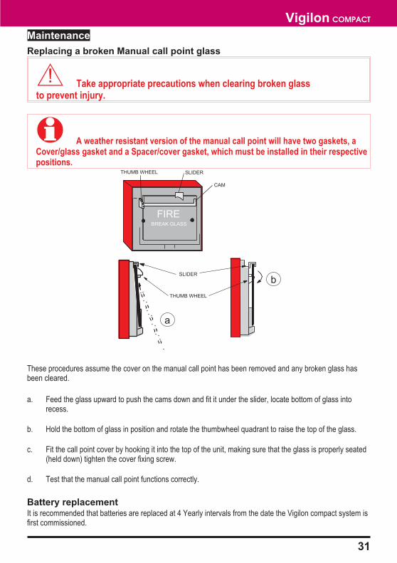
Replacing a broken Manual call point glass
� Take appropriate precautions when clearing broken glassto prevent injury.
� A weather resistant version of the manual call point will have two gaskets, aCover/glass gasket and a Spacer/cover gasket, which must be installed in their respectivepositions.
These procedures assume the cover on the manual call point has been removed and any broken glass hasbeen cleared.
a. Feed the glass upward to push the cams down and fit it under the slider, locate bottom of glass intorecess.
b. Hold the bottom of glass in position and rotate the thumbwheel quadrant to raise the top of the glass.
c. Fit the call point cover by hooking it into the top of the unit, making sure that the glass is properly seated(held down) tighten the cover fixing screw.
d. Test that the manual call point functions correctly.
Battery replacementIt is recommended that batteries are replaced at 4 Yearly intervals from the date the Vigilon compact system isfirst commissioned.
31
Vigilon COMPACT
FIREBREAK GLASS
THUMB WHEEL SLIDER
CAM
THUMB WHEEL
SLIDER
b
a

4188-751_issue 2_03/03