finite element modeling of lateral … pipeline soil interaction.pdf · employs a generalized...
TRANSCRIPT

14th International Conference on Offshore Mechanics and Arctic Engineering, OMAE 96, Florence, Italy, 1996 Page 1/9
FINITE ELEMENT MODELING OF LATERAL PIPELINE-SOIL INTERACTION
Ameir Altaee and Bengt H. Fellenius
Urkkada Technology Ltd., 1010 Polytek St., Unit 6, Ottawa, Ontario, Canada, K1J 9H8
ABSTRACT Lateral interaction between pipelines and overconsolidated soil is modeled using the Advanced Geotechnical Analysis Code (AGAC) finite element program. The analysis is elasto-plastic, coupled stress-consolidation type. The rate of lateral pipeline movement against the soil varies from slower than 1 mm/day through faster than 1,000 mm/day. The effects of soil overconsolidation and the location of the groundwater table are also addressed. The analysis addresses a typical full-scale buried pipe of 0.914 m diameter placed in a backfilled, 2.0 m wide and 1.8 m deep excavation. The analysis results show that the faster the pipeline moves against the soil, the larger the resulting interaction force. Soils with higher overconsolidation show larger interaction force for all rates of pipeline movement. The rate of movement of 1 mm/day and 1,000 mm/day define the drained and undrained boundaries of the interaction, respectively. For all rates of movement, the ground surface ahead of the pipeline heaves and forms a dome which size increase the slower the rate of pipeline movement. When the pipeline moves rapidly, a depression is formed behind the pipeline. Displacing the pipeline laterally causes simultaneous vertical movement. The slower the lateral pipeline movement, the larger the pipeline resulting upward movement toward the ground surface. When the interaction is undrained, the pipeline moves slightly downward as a result of the imposed lateral movement. A zone of very high shear strain below the moving pipeline is observed in all cases analyzed. This zone is larger when the interaction is undrained. Behind the pipeline, negative excess pore water pressure develops; releasing this pore pressure reduces the interaction force to about half. INTRODUCTION
Lateral interaction between pipelines and clays is governed by the rate of the interaction, overconsolidation and hydraulic conductivity of the clay, location of the groundwater table, and other factors. When the movement is slow enough and no excess pore water pressure generates, the soil response becomes drained. On the other hand, undrained soil response may occur when the movement is fast enough. For all other rates between these two boundaries, partial drained response of the soil occurs. Because overconsolidated clays have a quite different response in drained, undrained, and partial drained loading, different interaction forces are expected for the different interaction rates. The development of negative pore water pressure in the overconsolidated clay is an important factor in studying rate loading. Altaee and Boivin (1995) performed finite element analysis of lateral pipeline-soil interaction. The clay considered was slightly overconsolidated and the effect of negative excess pore water pressure was not obvious. As most natural clays are highly overconsolidated in the zone of pipeline placement, extending the Altaee and Boivin (1995) analysis for highly overconsolidated clays is needed. Therefore, the present study addresses the effect of rate of movement, location of the groundwater table, soil’s overconsolidation, and suction developing behind rapidly moving pipelines on the lateral interaction force. The study employs a generalized coupled stress-consolidation analysis and therefore, the drained and undrained cases of analyses are only special cases. In this paper, results of finite element analysis performed for a laterally displaced pipeline are presented. The pipe diameter and the size of trench were selected to represent full-scale conditions as documented by Rizkalla et al. (1993). The

14th International Conference on Offshore Mechanics and Arctic Engineering, OMAE 96, Florence, Italy, 1996 Page 2/9
native soil and the backfill material were considered to be overconsolidated clays. The AGAC finite element program with the bounding-surface plasticity model for clays (Altaee, 1992) is used. GEOMETRY ANALYZED A sectional elevation of the geometry analyzed is shown in Fig. 1. The pipe is 914 mm diameter placed in a backfilled 2.0 m wide and 1.8 m deep excavation with 0.9 m of soil backfilled above the crown of the pipe. These dimensions are similar to those encountered in practice as pointed out by Rizkalla et al. (1992) and used by Altaee and Boivin (1995) and Paulin et al. (1995). Altaee and Boivin (1995) performed finite element analysis to study lateral displacement of a pipeline by moving the soil laterally against the pipeline. In contrast, in the present analysis, the pipeline is moved laterally by imposing incremental lateral displacement on the pipe itself. This type of lateral interaction is commonly used in laboratory studies of pipeline soil interaction such as in Rizkalla et al. (1992) and Paulin et al. (1995). The resulting pipeline soil interaction caused by moving the pipeline against the soil rather than moving the soil against the pipeline is not necessarily fully representative to actual field conditions. However, it is selected in the present analysis for demonstrative purposes and to compare the analysis results to observations from laboratory testing.
FINITE ELEMENT PROGRAM AND SOIL MODEL The Advanced Geotechnical Analysis Code (AGAC), Altaee (1992) is used to perform the present analyses. The program incorporates several constitutive soil models including the modified Cam-clay model, Cap models, and bounding surface plasticity models for cohesionless and cohesive soils. The program is fully operational on a PC Computer. Incremental-iterative procedures are used to deal with the non-linearity of the soil behavior. All analyses performed in this study are generalized coupled stress-consolidation type and, therefore, ideal drained and ideal undrained situations become special cases of the generalized method of analysis used here. The soil constitutive model has been successfully applied to heavily overconsolidated clays, which exhibit strain-softening and develop negative excess pore water pressure during shearing. Overconsolidated clays are very common in nature and particularly at shallow depths within the zone of interest for pipeline placement. The bounding surface plasticity model for clays (Altaee, 1992) is used to simulate the behavior of the soil. A brief description of the model and its formulation is presented in Altaee and Boivin (1995).
FIGURE 1 CASE ANALYZED

14th International Conference on Offshore Mechanics and Arctic Engineering, OMAE 96, Florence, Italy, 1996 Page 2/9
FINITE ELEMENT MODEL The finite element mesh used in the analysis is shown in Fig. 2. AGAC uses four-node isoparametric elements. The pipe is modeled as a linearly elastic material. Vertical and horizontal movements as well as water flow are prevented along the boundaries AB, BC, and CD. No restriction on movement or water flow is imposed along Boundary DA. The flow from the soil into the pipe is prevented by specifying the outer surface of the pipeline as an impervious boundary. The boundaries AB, BC, and CD are placed far enough to eliminate any effect of the boundaries on the analysis results. Interaction between the pipeline and soil is introduced by displacing the pipe laterally from left to right by applying increments of horizontal displacement as indicated in Fig. 2. Vertical movement of the pipe is not restricted.
ANALYSIS CASES Nine cases are analyzed to study the effects of rate of pipeline movement against the soil, overconsolidation of the soil, location of the groundwater table relative to the pipeline, and excess pore water pressure behind the pipeline. The cases analyzed are listed in Table 1. Other cases are also analyzed to define the analysis boundaries and to optimize the selection of the nine main cases. For all cases analyzed, the pipeline is moved incrementally to a maximum lateral movement of about 650 mm, corresponding to about 70 % of the pipeline diameter.
FIGURE 2 FINITE ELEMENT MESH
TABLE 1
Case No. Rate of σp’ Location of Description Notes
movement water table (term used) mm/day kPa
1 1 300 Surface Slow
2 10 300 Surface Rate 3 100 300 Surface effect 4 1000 300 Surface Rapid
5 1 300 Deep Dry Effect of water
6 1000 300 Deep Dry table location
7 1 100 Surface Effect of
8 1000 100 Surface overconsolidation
9 1000 300 Surface Effect of suction

14th International Conference on Offshore Mechanics and Arctic Engineering, OMAE 96, Florence, Italy, 1996 Page 4/9
Initial vertical effective stress in the soil at a specific depth is calculated considering hydrostatic pore pressure distribution. The corresponding horizontal stress is considered equal to the vertical stress. Overconsolidation stress of 300 kPa is assigned for most of the cases analyzed. For two of the cases, an overconsolidation stress of 100 kPa is used. The effect of rate of movement on the lateral load acting on the pipeline is studied by moving the pipeline at different rates. The rates are slower than 1 mm/day, 1 mm/day, 10 mm/day, 100 mm/day, 1,000 mm/day, and faster than 1,000 mm/day. For the conditions analyzed, rate of movement of 1 mm/day corresponds to drained conditions and pipeline rate of movement of 1,000 mm/day corresponds to undrained conditions. This means that the interaction response is identical when the rate of movement is equal or smaller than 1 mm/day. Similarly, the interaction is identical for all rates of movement equal to or larger than 1,000 mm/day. The groundwater table is placed at the surface when studying the effect of rate of movement. In the following, the drained and undrained cases are used as reference cases and called Slow and Rapid, respectively. Similar terminology has been used earlier by Altaee and Boivin (1995). The effect of soil overconsolidation is studied by repeating the analysis for the two reference cases, Slow and Rapid, but using overconsolidation stress of 100 kPa instead of 300 kPa. The effect of location of the water table is studied by performing two analysis cases with the groundwater table at two pipe diameters below the pipeline. The soil is considered dry in the zone above the groundwater table. The results of these two cases are then compared within the two reference cases where the water table is at the ground surface. When the ground water table is below the pipeline, the case analyzed is called Dry and used as a reference in subsequent comparisons. The effect of excess pore water pressure developing behind the moving pipeline is studied by comparing the results of the Rapid case with results when the pipeline is moved at 1,000 mm/day while releasing all excess pore water pressure developing in the soil behind the pipeline. Because the analysis is rate dependent, releasing the pore water pressure is achieved by assigning a very high value to the hydraulic conductivity for the soil at this location. For the soil elsewhere, the hydraulic conductivity is unchanged. MATERIAL PARAMETERS The soil parameters assigned for the analysis are shown in Table 2. For the pipeline material, a value of Young’s modulus of elasticity of 200 GPa and a Poisson’s ratio of 0.3 are used. Variations in these values have little effect on the results of analysis as the Young modulus of the pipe material (steel) is so much higher than that of soil.
Table 2
Parameter Native Fill soil
M 1.0 0.8
λ 0.3 0.5 κ 0.01 0.03 ν 0.3 0.3 c’ 5.0 5.0 k 1x10⁻⁸ m/s 1x10⁻⁸ m/s
RESULTS Lateral interaction force versus lateral pipeline movement Fig. 3 shows the lateral force acting on the pipeline at different rates. The force is proportional to the rate of pipeline movement. When the movement rate is about 1 mm/day, no excess pore water pressure develops anywhere in the soil and the pipeline soil interaction represents drained response. Similarly, when the pipeline movement rate is larger than about 1,000 mm/day, no further increase in the excess pore water pressure in the soil occurs and the interaction becomes undrained. The effect of overconsolidation of the soil on the lateral interaction force is illustrated in Fig. 4. For all pipeline movement rates, the larger the overconsolidation stress, the larger the lateral force. For pipeline lateral movement greater than 100 mm, the force is about doubled when the overconsolidation stress increased from 100 kPa to 300 kPa. This is true for slow as well as fast pipeline movement. Fig. 5 shows the effect of the water table location on the lateral force on the pipeline. When the water table is at the ground surface (an extreme situation) the soil is saturated and the effect of movement rate is evident. When the groundwater table is deep and the soil above the water table is dry, no rate effect is present. Because the effective stresses in the soil are larger when the groundwater table is deep, the lateral interaction force acting on the pipeline is larger. As presented earlier in Fig. 3, the lateral force acting on the pipeline is larger for a faster moving pipeline. This is due to the development of negative excess pore water pressure in the overconsolidated soil (as will be shown subsequently). This is conditional on that the soil can develop and maintain the negative pore water pressure, that is the soil is free of fissures and cracks particularly near the surface. The soil behind the pipeline develops relatively high excess pore water pressure when the pipeline moves rapidly. The effect on the lateral interaction force acting on the pipeline when the pore water pressure is released in the soil behind the pipeline is shown in Fig. 6. Considerable reduction in the lateral interaction force on the pipeline takes place when the soil releases the pore pressure. However, the resulting force after releasing the negative pore pressure is still larger than that of the Slow case.

14th International Conference on Offshore Mechanics and Arctic Engineering, OMAE 96, Florence, Italy, 1996 Page 5/9
0 200 400 600 8000
200
400
600
800
Pipeline lateral movement (mm)
Late
ral f
orce
(KN
/m)
FIGURE 3
EFFECT OF RATE OF MOVEMENT ON INTERACTION FORCE
0 200 400 600 8000
200
400
600
800
Pipeline lateral movement (mm)
Late
ral f
orce
(KN
/m)
FIGURE 4
EFFECT OF SOIL’S OVERCONSOLIDATION ON INTERACTION FORCE
0 200 400 600 8000
200
400
600
800
Pipeline lateral movement (mm)La
tera
l for
ce (K
N/m
)
≥ 1,000 mm/day (rapid) Rapid, water table at ground surface
100 mm/day
Rapid, water table at ground surface 10 mm/day
≤ 1 mm/day, (slow) Slow, water table at ground surface
FIGURE 5 EFFECT OF WATER TABLE LOCATION
ON INTERACTION FORCE
0 200 400 600 8000
200
400
600
800
Pipeline lateral movement (mm)
Late
ral f
orce
(KN
/m)
σp’ = 300 kPa, (rapid) Rapid, with pore pressure
σp’ = 100 kPa, (rapid)
Rapid, with pore pressure released σp
’ = 300 kPa, (slow)
σp’ = 100 kPa, (slow)
FIGURE 6 EFFECT OF SUCTION BEHIND PIPELINE
ON INTERACTION FORCE

14th International Conference on Offshore Mechanics and Arctic Engineering, OMAE 96, Florence, Italy, 1996 Page 6/9
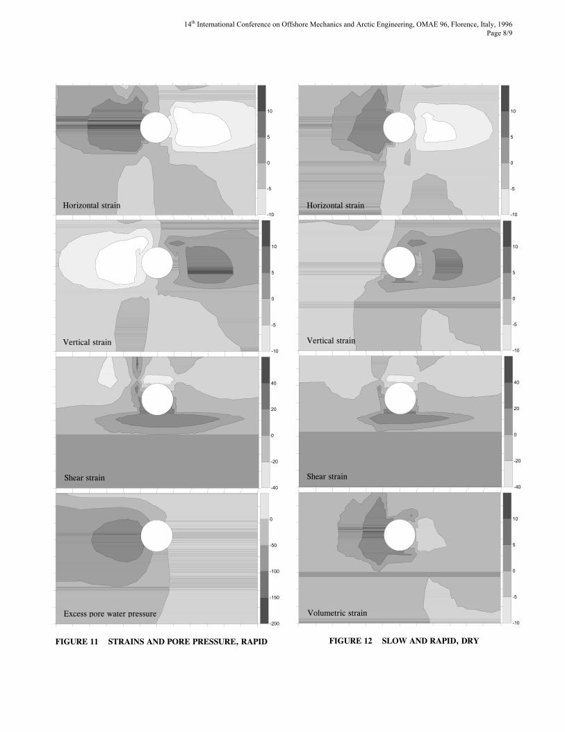
Displacements field Figs. 7 through 9 show the displacements field of the soil for the Slow, Rapid, and Dry cases, respectively. The lateral pipeline movement is 400 mm in all cases. Only the soil near the pipeline is shown in the figures because the movements are significantly smaller away from the pipeline. The magnitude of the nodal movements shown in these figures is not magnified. In all three cases shown, soil heave at the ground surface is evident. The ground surface is raised to form a dome-like shape that extends a few pipeline diameters ahead of the pipeline. The displacements fields are very similar in all cases within the soil zone at the front of the pipeline that indicate a considerable upward movement of the soil. Directly above as well as behind the pipeline, the displacements field of the Rapid movement case is different than those of the other two cases. When the pipeline moves rapidly, the soil behind the pipe moves downward and forms a depression, whereas the soil directly above the pipeline moves only laterally, acting as a transition zone between downward movement behind the pipeline and upward movement ahead of the pipeline. This considerable difference in the displacements fields are due to the development of negative excess pore pressure behind the pipeline in the case of Rapid pipeline movement. In all cases analyzed the pipeline moves vertically as a result of the imposed lateral movement. Considerable upward movement toward the ground surface occurs in the Slow case, as shown in Figs. 7 and 9. In contrast, downward movement of the pipeline occurs when the pipeline is subjected to rapid lateral movement. The downward movement, however, is very small as shown in Fig. 8. This implies that, as also shown earlier by Altaee and Boivin (1995), the total force (and, consequently, stresses and strains within the pipe) acting on the pipe would be larger for the pipe moving downward (rapid lateral movement in the present cases) as shown earlier in Fig. 3. Strains Field and excess pore water pressure Figs. 10 through 12 present the strains field in the soil as a result of the pipeline movement for Slow, Rapid, and Dry cases, respectively. The strains fields are for pipeline lateral movement of about 400 mm. Strains include horizontal, vertical, shear, and volumetric. The values shown are in percentage and negative values indicate compression and positive values indicate dilation or expansion. Qualitatively, similar strains fields are observed for the different cases. The soil ahead of the pipeline experiences compressional horizontal strains and expansive vertical strains, while the soil behind the pipeline experiences expansive horizontal strains and compressional vertical strains. The distinction between expansive and compression strains, however, is clearer in case of horizontal strains. Volumetric strains in case of Slow pipeline movement and excess pore water pressure in case of Rapid movement provide a better picture for the deformation scheme than the horizontal and vertical strains. For slow pipeline movement, when the
interaction is drained and no excess pore water pressure develops, the soil ahead of the pipeline compresses and the soil behind the pipe expands as indicated by the fields of volumetric strains (Figs. 10 and 12). In contrast, when the pipeline movement is rapid, the soil ahead of the pipeline as well as behind the pipeline, tends to dilate. This tendency for dilation causes negative excess pore water pressure to develop everywhere in the soil. The soil behind the pipeline experiences the largest tendency to dilate and, consequently, develops the largest excess pore water pressure. Negative excess pore water pressure in the soil is a characteristic of overconsolidated clays. When negative pore water pressure develops, the effective stresses of the soil increase and the forces required for moving the pipeline increase. Moving the pipeline a distance as long as 400 mm causes considerable shear strain to develop in the soil. For the three cases presented in Figs. 10 through 12, a distinct zone of high shear strain below the pipeline is evident. The zone of high shear strain is considerably larger when the pipeline moves rapidly. Furthermore, the zone of high shear strain in case of rapid pipeline movement extends toward the ground surface in the soil behind the pipeline as shown in Fig. 11. The development of a high shear strain zone below the pipeline was also observed during centrifuge testing as described by Paulin et al. (1995). Discussion The present analysis considers the effect of the rate of pipeline movement on the pipeline-soil lateral interaction force. Two distinct differences exist between the current analysis and those presented earlier by Altaee and Boivin (1995). The overconsolidation of the soils used in the present analysis is 300 kPa in most cases, whereas an overconsolidation ratio of only 1.8 was used previously. A high overconsolidation pressure for the soil is more representative for actual field conditions. Further, Altaee and Boivin (1995) moved the soil against the pipeline, whereas the pipeline is moved against the soil in the present analysis. The former better represents the field conditions while the latter represents tests conditions. Moving the pipeline toward the soil is not necessarily a better approach than moving the soil toward the pipeline. However, neither approach replicates actual field conditions. An ideal analysis of soil pipeline interaction should preserve the geometrical aspects of the pipeline and the soil which is in most cases involves a sloping ground moving toward the pipeline. Moving the pipeline against the soil and moving the soil against the pipeline yield opposing rate effect results. When the soil moves against the pipeline, the slower the movement, the larger the resulting lateral force on the pipeline. On the other hand, when the pipeline moves against the soil, the slower the movement, the smaller the resulting lateral force on the pipeline. This distinct difference is due to the different stresses, strains, and excess pore water pressure develop in the soil for the two different situations. That is, the rate effect on the pipeline

14th International Conference on Offshore Mechanics and Arctic Engineering, OMAE 96, Florence, Italy, 1996 Page 7/9
FIGURE 7 DISPLACEMENTS FIELD, SLOW MOVEMENTS
FIGURE 8 DISPLACEMENTS FIELD, RAPID MOVEMENT
WITH FULL SUCTION BEHIND PIPELINE
FIGURE 9 DISPLACEMENTS FIELD, SLOW AND RAPID
MOVEMENT, DRY SOIL
-10
-5
0
5
10
Horizontal strain
-10
-5
0
5
10
Vertical strain
-40
-20
0
20
40
Shear strain
-10
-5
0
5
10
Volumetric strain
FIGURE 10 STRAINS, SLOW
14th International Conference on Offshore Mechanics and Arctic Engineering, OMAE 96, Florence, Italy, 1996 Page 8/9
-10
-5
0
5
10
-10
-5
0
5
10
-40
-20
0
20
40
-200
-150
-100
-50
0
FIGURE 11 STRAINS AND PORE PRESSURE, RAPID
-10
-5
0
5
10
Horizontal strain Horizontal strain
-10
-5
0
5
10
Vertical strain Vertical strain
-40
-20
0
20
40
Shear strain Shear strain
-10
-5
0
5
10
Volumetric strain Excess pore water pressure
FIGURE 12 SLOW AND RAPID, DRY

14th International Conference on Offshore Mechanics and Arctic Engineering, OMAE 96, Florence, Italy, 1996 Page 9/9
soil interaction is controlled by the way the movement of a slope, for example, is introduced. Furthermore, as observed in many sites by Scarpelli et al. (1995), slope movements do not occur continuously in time but only occasionally when some critical conditions are met. This means that actual situations involve variable rate of movement with time. This has not been addressed yet in numerical analysis or experimentation. In the present analysis when modeling the slow pipeline movement, the soil parameters are kept unchanged with time. That is, throughout the 600-day duration of moving the pipeline 600 mm, no changes took place in groundwater level or any other characteristics of the soil. This may not represent actual field conditions. However, it provides a controlled analysis to determine the effects of rate of movement only. This control of the environment could be difficult in field or laboratory testing. Results of centrifuge tests simulating slow pipeline interaction presented by Paulin et al. (1995) could include the effect of factors other than the rate of pipeline movement. In the tests, the water table was kept below the pipeline at all times. The soil above the water table (controlling the interaction) is therefore subjected to different testing conditions when the tests involve slow or rapid pipeline movement. There is a good reason to believe that the strength of the soil above the water table has improved considerably during the extended period of time of centrifuge spinning. The spinning time during the slow pipeline movement test was as much as 1,300 times that of the cases of rapid pipeline movement. This could be the reason for obtaining considerably higher interaction force in case of slower pipeline movement. Considerable negative excess pore water pressure develops in the soil behind the moving pipeline. This results in higher lateral interaction forces against the pipeline. When the pore pressure at this location is released, the interaction force reduces to about half. This agrees very well with results from Rowe and Davis (1982). In their numerical analyses of plates moved laterally in clay, Rowe and Davis (1982) showed that the force resulting from moving the plate laterally against the soil is reduced to about half when the plate separates immediately from the soil behind. That is, suction was prevented from developing behind the moving plate. CONCLUSIONS When a pipeline is moved laterally against an overconsolidated clay, lateral interaction force develops. The faster the pipeline moves, the larger the resulting interaction force. For the clay considered in the present analysis, pipeline movement rate of 1 mm/day and 1,000 mm/day define the bounds of drained and undrained interaction, respectively. Any movement rate that is faster than 1,000 mm/day would not result in any further increase in the interaction force. Similarly, any movement rate that is slower than 1 mm/day would not result in any further reduction in the interaction force. These drained and undrained rates of movement depend on the hydraulic conductivity of the soil. The more permeable
the soil, the faster the rate of pipeline movement needed to result in undrained interaction. For all rates of pipeline movements, the higher the overconsolidation stress of the soil, the higher the resulting interaction force for the same lateral pipeline displacement. When the groundwater table is far below the pipeline, the resulting interaction force becomes independent of the rate of movement. For the same soil and pipeline, the interaction force when the soil is dry is larger than the interaction force of a slowly moving pipeline and smaller than the force of a rapidly moving pipeline when the ground water table is at the surface. Negative excess pore water pressure develops behind a rapidly moving pipeline. The faster the rate of movement, the larger the resulting pore water pressure. When the negative pore water pressure is released fully from the soil behind the pipeline, the interaction force reduces to about half that when the pore water pressure is allowed to develop fully. Under a moving pipeline, a zone of high shear strain develops. The faster the pipeline moves the larger this zone. In case of rapid movement, the zone extends to the ground surface in the soil behind the pipeline. Pipeline movement causes the soil to heave at the ground surface in a dome shape. The slower the movement the larger the dome. The formation of a depression at the ground surface is also observed when pipeline movement is rapid. This is due to the large suction developing behind the rapidly moving pipeline. When the suction is released, the ground depression does not develop. The way the lateral interaction is introduced, the pipeline moves against the soil or the soil moves against the pipeline, affects the stresses, strains, and pore water pressure regimes and, therefore, the magnitude of lateral interaction force as a function of the rate of movement. REFERENCES Altaee, A. 1992. A simple bounding surface plasticity model for clays. Unpublished internal research report. Department of Civil Engineering, University of Ottawa, Ottawa, Ontario. Altaee, A., and Boivin, R., 1995. Laterally displaced pipelines: finite element analysis. In Proceedings, 14th Offshore Mechanics and Arctic Engineering Conference, June 18-22, Copenhagen, Denmark, pp. 209-216. Paulin, M.J., Phillips, R., and Boivin, R., 1995. Centrifuge modeling of lateral pipeline/soil interaction - Phase II. In Proceedings, 14th Offshore Mechanics and Arctic Engineering Conference, June 18-22, Copenhagen, Denmark, pp. 107-123. Rizkalla, M., Poorooshasb, F., and Clark, J., 1992. Centrifuge modeling of lateral pipeline/soil interaction. In Proceedings, 11th Offshore Mechanics and Arctic Engineering Conference, June 7-11, Calgary, Alberta,.. 13p. Insert Rowe, R.K., and Davis, E.H., 1982. The behavior of Anchor plates in clay. Geotechnique, Volume 32, No. 1, pp. 9-23. Scarpelli, G., Aleoti, P., Baldelli, P., Milani, G., and Brambati, E. 1995. Field experiences of pipelines in geologically unstable areas. In Proceedings, 14th Offshore Mechanics and Arctic Engineering Conference, June 18-22, Copenhagen, Denmark, pp. 87-94.