fingerprint sourcebook chapter 6: automated … fingerprint identification system (afis) ... chapter...
TRANSCRIPT

C h a p t e r
C O N t e N t S
3
9
15
20
6.1 Introduction
6.2 AFIS Operations
6.3 Standards
6.4 Digitization and Processing of Fingerprints
AutomAted Fingerprint identiFicAtion system (AFis) Kenneth R. Moses Contributing authors Peter Higgins, Michael McCabe, Salil Probhakar, Scott Swann
32
33
32
31 6.5 Summary
6.6 Reviewers
6.7 References
6.8 Additional Information


Chapter 6
AutomAted FingerprintidentiFicAtion system (AFis) Kenneth R. Moses Contributing authors Peter Higgins, Michael McCabe, Salil Probhakar, Scott Swann
6.1 Introduction Prior to the industrial revolution and the mass migrations to the cities, populations lived mostly in rural communities where everyone knew everyone else and there was little need for identification. Indeed, there were no police forces, no penitentiaries, and very few courts. As cities became crowded, crime rates soared and criminals flourished within a sea of anonymity. Newspapers feasted on stories of lawlessness, legislatures quickly responded with more laws and harsher penalties (especially for repeat offenders), and police departments were charged with identifying and arresting the miscreants. Identification systems—rogues’ galleries, anthropometry, Bertillon’s “portrait parlé”, and the Henry system—emerged and quickly spread worldwide at the end of the 19th and beginning of the 20th century.
The late 1960s and early 1970s witnessed another era of civil turmoil and an unprecedented rise in crime rates, but this era happened to coincide with the development of the silicon chip. The challenges inherent in identification systems seemed ready-made for the solutions of auto-matic data processing, and AFIS—Automated Fingerprint Identification System—was born.
During this same period, The RAND Corporation, working under a national grant, published The Criminal Investigative Process (Greenwood et al., 1975), a comprehensive study and critique of the process by which crimes get solved—or do not. Generally critical of traditional methods used by detectives, the study placed any hopes for improvement on physical evidence in general and latent prints in particular. In a companion study, Joan Petersilia concluded that:
No matter how competent the evidence techni-cian is at performing his job, the gathering of physical evidence at a crime scene will be futile unless such evidence can be properly processed and analyzed. Since fingerprints are by far the most frequently retrieved physical evidence, mak-ing the system of analyzing such prints effective will contribute the most toward greater success in identifying criminal offenders through the use of physical evidence. (Petersilia, 1975, p 12)
6–3
AFIS c h A p t e r 6

Though new technology was already in development at the Federal Bureau of Investigation (FBI), it would be a popular movement at the local and state levels that would truly test Petersilia’s theory.
6.1.1 Need For Automation In 1924, the FBI’s Identification Division was established by authority of the United States congressional budget ap-propriation bill for the Department of Justice. The identifica-tion division was created to provide a central repository of criminal identification data for law enforcement agencies throughout the United States. The original collection of fingerprint records contained 810,188 records. After its cre-ation, hundreds of thousands of new records were added to this collection yearly, and by the early 1960s the FBI’s criminal file had grown to about 15 million individuals. This was in addition to the 63 million records in the civilian file, much of which was the result of military additions from World War II and the Korean conflict.
Almost all of the criminal file’s 15 million individuals contained 10 rolled fingerprints per card for a total of 150 million single fingerprints. Incoming records were manually classified and searched against this file using the FBI’s modified Henry system of classification. Approxi-mately 30,000 cards were searched daily. The time and human resources to accomplish this daily workload continued to grow. As a card entered the system, a preliminary gross pattern classification was assigned to each fingerprint by technicians. The technicians could complete approximately 100 fingerprint cards per hour. Complete classification and searching against the massive files could only be accomplished at an average rate of 3.3 cards per employee per hour. Obviously, as the size of the criminal file and the daily workload increased, the amount of resources required continued to grow. Eventually, classification extensions were added to reduce the portion of the criminal file that needed to be searched against eachcard. Nonetheless, the manual system used for searching and matching fingerprints was approaching the point of being unable to handle the daily workload.
Although punch card sorters could reduce the number of fingerprint cards required to be examined based on patternclassification and other parameters, it was still necessary for human examiners to scrutinize each fingerprint card on the candidate list. A new paradigm was necessary to stop the increasing amount of human resources required
to process search requests. A new automated approach was needed to (1) extract each fingerprint image from a tenprint card, (2) process each of these images to produce a reduced-size template of characteristic information, and (3) search a database to automatically produce a highly reduced list of probable candidate matches (Cole, 2001, pp 251–252).
6.1.2 Early AFIS Development In the early 1960s, the FBI in the United States, the Home Office in the United Kingdom, Paris Police in France, and the Japanese National Police initiated projects to develop automated fingerprint identification systems. The thrust of this research was to use emerging electronic digital com-puters to assist or replace the labor-intensive processes of classifying, searching, and matching tenprint cards used for personal identification.
6.1.3 FBI AFIS Initiative By 1963, Special Agent Carl Voelker of the FBI’s Identifi-cation Division realized that the manual searching of the criminal file would not remain feasible for much longer. In an attempt to resolve this problem, he sought the help of en-gineers Raymond Moore and Joe Wegstein of the National Institute of Standards and Technology (NIST)1. After describ-ing his problem, he asked for assistance in automating the FBI’s fingerprint identification process.
The NIST engineers first studied the manual methods used by human fingerprint technicians to make identifications. These methods were based on comparing the minutiae (i.e., ridge endings and ridge bifurcations) on fingerprint ridg-es. If the minutiae from two fingerprints were determined to be topologically equivalent, the two fingerprints were declared to be identical—that is, having been recorded from the same finger of the same person. After this review, and after studying additional problems inherent with the inking process, they believed that a computerized solution to auto-matically match and pair minutiae could be developed that would operate in a manner similar to the techniques used by human examiners to make fingerprint identifications. But to achieve this goal, three major tasks would have to be accomplished. First, a scanner had to be developed that could automatically read and electronically capture the inked fingerprint image. Second, it was necessary to accurately
1 NIST was known as the National Bureau of Standards when the FBI visited Moore and Wegstein.
6–4
c h A p t e r 6 AFIS

and consistently detect and identify minutiae existing in the captured image. Finally, a method had to be developed to compare two lists of minutiae descriptors to determine whether they both most likely came from the same finger of the same individual.
The Identification Division of the FBI decided that the approach suggested by Moore and Wegstein should be followed. To address the first two of the three tasks, on December 16, 1966, the FBI issued a Request for Quotation (RFQ) “for developing, demonstrating, and testing a device for reading certain fingerprint minutiae” (FBI, 1966). This con-tract was for a device to automatically locate and determine the relative position and orientation of the specified minutiae in individual fingerprints on standard fingerprint cards to be used for testing by the FBI. The requirements stated that the reader must be able to measure and locate minutiae in units of not more than 0.1 mm and that the direction of each minutiae must be measured and presented as output in units of not more than 11.25 degrees (1/32 of a full circle). The initial requirements called for a prototype model to process 10,000 single fingerprints (1,000 cards). Contractors were also instructed to develop a proposal for a subsequent contract to process 10 times that number of fingerprints.
The 14 proposals received in response to this RFQ were divided into 5 broad technical approaches. At the conclusion of the proposal evaluation, two separate proposals were funded to provide a basic model for reading fingerprint im-ages and extracting minutiae. Both proposed to use a “flying spot scanner” for capturing the image. But each offered a different approach for processing the captured image data, and both seemed promising. One contract was awarded to Cornell Aeronautical Labs, Inc., which proposed using a general-purpose digital computer to process binary pixels and develop programs for detecting and providing measure-ment parameters for each identified minutiae. The second contract was awarded to North American Aviation, Inc., Autonetics Division, which proposed using a special-purpose digital process to compare fixed logical marks to the image for identifying, detecting, and encoding each minutia.
While the devices for fingerprint scanning and minutiae detection were being developed, the third task of comparing two minutiae lists to determine a candidate match was ad-dressed by Joe Wegstein (Wegstein, 1969a, 1970, 1972 a/b, 1982; Wegstein and Rafferty, 1978, 1979; Wegstein et al., 1968). He developed the initial algorithms for determining fingerprint matches based on the processing and compari-
son of two lists describing minutiae location and orientation. For the next 15 years, he continued to develop more reliable fingerprint matching software that became increasingly more complex in order to account for such things as plastic distortion and skin elasticity. Algorithms he developed were embedded in AFISs that were eventually placed in operation at the FBI and other law enforcement agencies.
By 1969, both Autonetics and Cornell had made significant progress on their feasibility demonstration models. In 1970, a Request for Proposal (RFP) was issued for the construc-tion of a prototype fingerprint reader to reflect the experi-ence gained from the original demonstration models with an additional requirement for speed and accuracy. Cornell was awarded the contract to deliver the prototype reader to the FBI in 1972. After a year’s experience with the prototype system, the FBI issued a new RFP containing additional re-quirements such as a high-speed card-handling subsystem. In 1974, Rockwell International, Inc., was awarded a contract to build five production model automatic fingerprint reader systems. This revolutionary system was called Finder. These readers were delivered to the FBI in 1975 and 1976. The next 3 years were devoted to using these readers in the conver-sion of 15 million criminal fingerprint cards (Moore, 1991, pp 164–175).
As it became apparent that the FBI’s efforts to automate the fingerprint matching process would be successful, state and local law enforcement agencies began to evaluate this new technology for their own applications. The Minneapolis– St. Paul system in Minnesota was one of the first automat-ed fingerprint matching systems (after the FBI’s) to be in-stalled in the United States. Further, while the United States was developing its AFIS technology in the 1960s, France, the United Kingdom, and Japan were also doing research into automatic fingerprint image processing and matching.
6.1.4 French AFIS Initiative In 1969, M. R. Thiebault, Prefecture of Police in Paris, re-ported on the French efforts. (Descriptions of work done by Thiebault can be found in the entries listed in the Additional Information section of this chapter.) France’s focus was on the solution to the latent fingerprint problem rather than the general identification problem that was the concern in the United States. The French approach incorporated a vidicon (a video camera tube) to scan photographic film transparencies of fingerprints. Scanning was done at 400 pixels per inch (ppi), which was less than an optimal scan
6–5
AFIS c h A p t e r 6

rate for latent work. This minutiae matching approach was based on special-purpose, high-speed hardware that used an array of logical circuits. The French also were interested in resolving the problem of poor fingerprint image quality. In order to acquire a high-contrast image that would be easy to photograph and process, a technique was devel-oped to record live fingerprint images photographically using a principle of “frustrated total internal reflection” (FTIR). Although not put into large-scale production at that time, 20 years later FTIR became the cornerstone for the development of the modern-day livescan fingerprint scan-ners. These are making the use of ink and cards obsolete for nonforensic identification purposes today.
By the early 1970s, the personnel responsible for develop-ment of France’s fingerprint automation technology had changed. As a result, there was little interest in pursuing automated fingerprint identification research for the next several years. In the late 1970s, a computer engineering subsidiary of France’s largest financial institution responded to a request by the French Ministry of Interior to work on automated fingerprint processing for the French National Police. Later, this company joined with the Morphologic Mathematics Laboratory at the Paris School of Mines to form a subsidiary called Morpho Systems that went on to develop a functioning. Currently, Morpho Systems is part of Sagem (also known as Group SAFRAN).
6.1.5 United Kingdom AFIS Initiative During the same period of time, the United Kingdom’s Home Office was doing research into automatic fingerprint identification. Two of the main individuals responsible for the United Kingdom’s AFIS were Dr. Barry Blain and Ken Millard. (Papers produced by Millard are listed in the Addi-tional Information section of this chapter). Like the French, their main focus was latent print work. By 1974, research was being done in-house with contractor assistance from Ferranti, Ltd. The Home Office developed a reader to detect minutiae, record position and orientation, and determine ridge counts to the five nearest neighbors to the right of each minutia. This was the first use of ridge count information by an AFIS vendor (Moore, 1991).
6.1.6 Japanese AFIS Initiative Like France and the United Kingdom, Japan’s motivation for a fingerprint identification system was directed toward the matching of latent images against a master file of rolled
fingerprints. Japan’s researchers believed that an accurate latent system would naturally lead to the development of an accurate tenprint system.
By 1966, the Osaka Prefecture Police department housed almost 4 million single fingerprints. An early automation effort by this agency was the development of a pattern classification matching system based on a 17- to 20-digit number encoded manually (Kiji, 2002, p 9). Although this approach improved the efficiency of the totally manual method enormously, it had inherent problems. It required a great deal of human precision and time to classify the latents and single fingerprints; was not fully suitable for latent matching; and produced a long list of candidates, resulting in expensive verifications.
Within a few years, the fingerprint automation focus of Japanese researchers had changed. By 1969, the Iden-tification Section of the Criminal Investigation Bureau, National Police Agency of Japan (NPA), approached NEC to develop a system for the computerization of fingerprint identification. NEC determined that it could build an auto-mated fingerprint identification system employing a similar minutiae-based approach to that being used in the FBI system under development. At that time, it was thought that a fully automated system for searching fingerprints would not be realized for 5 to 10 years. In 1969, NEC and NPA representatives visited the FBI and began to learn about the current state of the art for the FBI’s AFIS plans. During the same period, NPA representatives also col-laborated with Moore and Wegstein from NIST. Additional AFIS sites were visited where information was acquired regarding useful and worthless approaches that had been attempted. All of this information was evaluated and used in the development of the NEC system.
For the next 10 years, NEC worked to develop its AFIS. In addition to minutiae location and orientation, this sys-tem also incorporated ridge-count information present in the local four surrounding quadrants of each minutiae under consideration for pairing. By 1982, NEC had suc-cessfully installed its system in the NPA and started the card conversion process. Within a year, latent inquiry searches began.
In 1980, NEC received a U.S. patent for automatic minutiae detection. It began marketing its automated fingerprint iden-tification systems to the United States a few years later.
6–6
c h A p t e r 6 AFIS

6.1.7 The Politicization of Fingerprints and the San Francisco Experiment Early development and implementation of automated fingerprint systems was limited to national police agencies in Europe, North America, and Japan. But the problems associated with huge national databases and the newborn status of computer technology in the 1970s limited the utility of these systems. Government investment in AFIS was justified largely on the promise of efficiency in the processing of incoming tenprint records. But funding these expensive systems on the local level would demand some creativity (Wayman, 2004, pp 50–52).
Following the success of the FBI’s Finder, Rockwell took its system to market in the mid-1970s. Rockwell organized a users group for its Printrak system and sponsored an annual conference for customers and would-be custom-ers. Starting with a beta-site in San Jose, California, more than a dozen installations were completed in quick succes-sion. Peggy James of the Houston Police Department, Joe Corcoran from Saint Paul, Donna Jewett from San Jose, and others devoted their energies toward educating the international fingerprint community on the miracle of the minutiae-based Printrak system. Each system that came online trumpeted the solution of otherwise unsolvable crimes and the identity of arrested criminals. A users group newsletter was published and distributed that highlighted some of the best cases and listed the search statistics of member agencies.
Ken Moses of the San Francisco Police Department had at-tended several of those Printrak conferences and became a staunch crusader for fingerprint automation. In three successive years, he persuaded the Chief of Police to include a Printrak system in the city budget, but each time it was vetoed by the mayor. After the third mayoral veto, a ballot proposition was organized by other politicians. The proposition asked citizens to vote on whether they wanted an automated fingerprint system. In 1982, Proposition E passed with an 80% plurality.
The mayor refused to approve a sole-source purchase from Rockwell, even though it was the only system in the world being marketed. She insisted on a competitive bid with strict evaluation criteria and testing. While on a trade mission to Japan, the mayor learned that the Japanese National Police were working with NEC to install a finger-print system, but NEC stated that the system was being developed as a public service and the company had no
plans to market it. After meeting with key Japanese of-ficials, NEC changed its mind and agreed to bid on the San Francisco AFIS.
When the bids were opened, not only had Printrak and NEC submitted proposals, but a dark horse named Logica had also entered the fray. Logica had been working with the British Home Office to develop a system for New Scotland Yard.
San Francisco retained systems consultant Tim Ruggles to assist in constructing the first head-to-head benchmark tests of competing in-use fingerprint systems. The test was most heavily weighted toward latent print accuracy, and a set of 50 latent prints graded from poor to good from actual past cases was searched against a prescribed ten-print database. All tests were conducted at the respective vendor’s home site.2 NEC was awarded the contract and installation was completed in December 1983.
Besides being the first competitive bid on 1980s technol-ogy, what differentiated the San Francisco system from those that had gone before was organizational design. AFIS was viewed as a true system encompassing all as-pects of friction ridge identification—from the crime scene to the courtroom. The AFIS budget included laboratory and crime scene equipment, training in all phases of forensic evidence, and even the purchase of vehicles. In 1983, a new crime scene unit was organized specifically with the new system as its centerpiece. Significant organizational changes were put into effect:
1. All latents that met minimum criteria would be searched in AFIS.
2. A new unit called Crime Scene Investigations was created and staffed on a 24/7 schedule.
3. Department policies were changed to mandate that patrol officers notify crime scene investigators of all felonies with a potential for latent prints.
2 The results of the earliest competitive benchmark tests were published by the International Association for Identification in 1986 (Moses, 1986). Thereafter, some vendors often demanded that the results of benchmark tests be kept secret, and law enforcement agencies generally acquiesced to those demands. This has made it extremely difficult for researchers and prospective purchasers to evaluate competing systems. The veil of secrecy has generally carried over to the sharing of AFIS operational performance data by agency personnel who often develop a strong sense of loyalty to their AFIS vendor.
6–7
AFIS c h A p t e r 6

c h A p t e r 6 AFIS
4. All crime scene investigators who processed the crime scenes were trained in the use of the system and encouraged to search their own cases.
5. Performance statistics were kept from the beginning, and AFIS cases were tracked through the criminal justice system to the courts.
The result of the San Francisco experiment was a dramatic 10-fold increase in latent print identifications in 1984. The district attorney demanded and got five new positions to prosecute the AFIS cases. The conviction rate in AFIS-generated burglary cases was three times higher than in burglary cases without this type of evidence (Figure 6–1; Bruton, 1989).
At a time when burglary rates were steeply rising in cities across the nation, the burglary rate plummeted in San Francisco (Figure 6–2; Bruton, 1989). Reporters, academics, and police administrators from around the world inundated the San Francisco Police Department for demonstrations and information.
The importance of politics and publicity was not lost on other agencies. Los Angeles even enlisted the backing of film stars to stir up public support. The identification of serial killer Richard Ramirez, the infamous Night Stalker, through a search of the brand-new California State AFIS made worldwide headlines and guaranteed the future funding of systems in California.
6.1.8 AFIS Proliferation The widely publicized success in San Francisco provided the spark for the rapid proliferation of new AFIS installations along with a methodology of benchmark testing to evaluate the claims of the growing number of competing vendors. Governments quickly provided funding so that, by 1999, the International Association for Identification’s (IAI’s) AFIS Directory of Users identified 500 AFIS sites worldwide (IAI, 1999).
The burgeoning market in these multimillion-dollar systems put forensic identification on the economic map. Commercial exhibits at IAI’s conferences that had formerly featured companies hawking tape and powder now expanded to digital image enhancement, lasers and forensic light sources, and the latest in new developments from Silicon Valley. The San Francisco Crime Lab received its first digital imaging system in 1986. This 3M/Comtal system was dedicated to friction ridge enhancement. Fingermatrix installed the first livescan device in the San Francisco Police Identification Bureau in 1988. AFIS brought crime scene and forensic identification out of the basement; no local or state law enforcement administrator wanted to be accused of being left behind.
However, the frenzied expansion of AFIS was not always logical and rational. By the early 1990s, the four biggest vendors—Printrak, NEC, Morpho, and Cogent—were in
DISPOSITIONS OF ADULT FELONY ARRESTS FIgUrE 6–1 ALL FELONIES 1986–1988
Tracking latent hits CALIFORNIA SAN FRANCISCO AFIS 7.92% 8.10%through the courts.
19.32% 44.82%(Bruton, 1989.) 27.74% 19.05% 25.80%
14.08%
15.75% 29.54% 66.10%21.06%
BURGLARIES 1986–1988 CALIFORNIA SAN FRANCISCO AFIS
6.46% 6.40% 24.83%8.44%
23.60% 10.74%
31.25% 29.93%
21.26% 43.12% 23.98% 70.00%
Law Enforcement Releases Dismissed or Acquitted by Courts County Jail or Probation
Complaints Denied by Prosecutor State Prison
6–8

FIgUrE 6–2 Statistical study of AFIS hits vs. burglaries in San Francisco, 1984–1988. (Bruton, 1989.)
competition, each offering proprietary software that was incompatible with the others, especially in latent print searching.
Expansion was often based on political considerations and competing mission priorities. Local and state agencies ex-pressed differences in priorities in terms of system design, with states generally emphasizing criminal identification or tenprint functions, while cities and counties focused on crime solving or latent print functions. Generally, the demands of latent print processing on computer resources far exceeded the requirements of tenprint processing, and states balked at the additional expense and technical complexity. As a result, cities, counties, and states often went their separate ways, installing dissimilar systems that could not communicate with neighboring jurisdictions or with the central state repository. Vendors eagerly encour-aged this fragmentation in an attempt to gain market share and displace competitors whenever possible. The evolu-tion of electronic transmission standards (see section 6.3) ameliorated this problem for tenprint search but not for latent search.
6.2 AFIS Operations
6.2.1 AFIS Functions and Capabilities Identification bureaus are legislatively mandated to main-tain criminal history records. Historically, this meant huge file storage requirements and cadres of clerks to maintain and search them. Demographic-based criminal history computers were established well ahead of AFIS, first as IBM card sort systems and then as all-digital information systems with terminals throughout the state and, via the
National Crime Information Center (NCIC) network and the National Law Enforcement Teletype System (Nlets), throughout the nation. These automated criminal his-tory systems became even more labor-intensive than the paper record systems they supposedly replaced. In many systems, more paper was generated and placed into the history jackets along with the fingerprint cards, mug shots, warrants, and other required documents.
AFIS revolutionized state identification bureaus because it removed from the paper files the last document type that could not previously be digitized—the fingerprint card. State identification bureaus could now bring to their legislatures cost–benefit analyses that easily justified the purchase of an automated fingerprint system through the reduction of clerical personnel.
Local and county jurisdictions did not usually enjoy the eco-nomic benefits of state systems. Pre-AFIS personnel levels were often lower and controlled more by the demands of the booking process than by file maintenance. AFIS generally increased staffing demands on the latent and crime-scene-processing side because it made crime scene processing dramatically more productive. Local and county AFIS purchases were usually justified on the basis of their crime-solving potential.
6.2.1.1 Technical Functions. Law enforcement AFISs are composed of two interdependent subsystems: the tenprint (i.e., criminal identification) subsystem and the latent (i.e., criminal investigation) subsystem. Each subsystem oper-ates with a considerable amount of autonomy, and both are vital to public safety.
The tenprint subsystem is tasked with identifying sets of inked or livescan fingerprints incident to an arrest or
1,584 Burglars ID’d Average Sentence = 4.4 Years
June 1983
Dec 1983
June 1984
Dec 1984
Dec 1985
Dec 1986
Dec 1987
June 1985
June 1986
June 1987
June 1988
7000
6500
6000
5500
5000
4500
4000
AFIS Begins
AFIS and Burglary in San Francisco
1984–1988 = 26% Decrease
Num
ber
of A
ctua
l Bur
glar
ies
per
6-M
onth
Per
iod
6–9
AFIS c h A p t e r 6

citation or as part of an application process to determine whether a person has an existing record.
In many systems, identification personnel are also charged with maintaining the integrity of the fingerprint and criminal history databases. Identification bureau staffs are generally composed of fingerprint technicians and supporting clerical personnel.
An automated tenprint inquiry normally requires a minu-tiae search of only the thumbs or index fingers. Submitted fingerprints commonly have sufficient clarity and detail to make searching of more than two fingers unnecessary. Today’s AFIS can often return a search of a million records in under a minute. As databases have expanded across the world, some AFIS engineers have expanded to searching four fingers or more in an effort to increase accuracy.
The latent print or criminal identification subsystem is tasked with solving crimes though the identification of latent prints developed from crime scenes and physical evidence. Terminals used within the latent subsystem are often specialized to accommodate the capture and digital enhancement of individual latent prints. The latent subsys-tem may be staffed by latent print examiners, crime scene investigators, or laboratory or clerical personnel. The staff of the latent subsystem is frequently under a different command structure than the tenprint subsystem and is often associated with the crime laboratory.
The search of a latent print is more tedious and time- consuming than a tenprint search. Latent prints are often fragmentary and of poor image quality. Minutiae features are normally reviewed one-by-one before the search be-gins. Depending on the portion of the database selected to be searched and the system’s search load, the response may take from a few minutes to several hours to return.
Most law enforcement AFIS installations have the ability to perform the following functions:
• Searchasetofknownfingerprints(tenprints)against an existing tenprint database (TP–TP) and return with results that are better than 99% accurate.3
• Searchalatentprintfromacrimesceneorevidence against a tenprint database (LP–TP).
3 This figure is based on requirements found in award documents and benchmark testing rather than operational observation.
• Searchalatentfromacrimesceneagainstlatentson file from other crime scenes (LP–LP).
• Searchanewtenprintadditiontothedatabaseagainst all unsolved latent prints in file (TP–LP).
Enhancements have been developed to allow other func-tions that expand AFIS capabilities, including:
• Additionofpalmprintrecordstothedatabasetoallow the search of latent palmprints from crime scenes.
• InterfacingofAFISwithothercriminaljusticeinforma-tion systems for added efficiency and “lights out”4 operation.
InterfacingofAFISwithdigitalmugshotsystemsand livescan fingerprint capture devices.
Additionofhand-heldportabledevicesforuseinidentity queries from the field. The query is initiated by scanning one or more of the subject’s fingers, extracting the mi-nutiae within the device, and transmitting to AFIS, which then returns a hit or no-hit (red light, green light) result. Hit notification may be accompanied by the thumbnail image of the subject’s mug shot.
•
•
• Multimodalidentificationsystems,includingfingerprint, palmprint, iris, and facial recognition, are now available.
6.2.2 System Accuracy Most dedicated government computer systems are based on demographic data such as name, address, date of birth, and other information derived from letters and numbers. For example, to search for a record within the motor vehicle database, one would enter a license number or operator data. The success of the search will be dependent on the accuracy with which the letters and numbers were originally perceived and entered. The inquiry is straight- forward and highly accurate at finding the desired record.
Automated fingerprint systems are based on data extract-ed from images. Although there is only one correct spelling for a name in a motor vehicle database, a fingerprint image can be scanned in an almost infinite number of ways. Success in searching fingerprints depends on the clarity of the images and the degree of correspondence between
4 “Lights out” generally refers to the ability of the system to operate without human intervention.
6–10
c h A p t e r 6 AFIS

the search print and the database print (compression and algorithms are two other factors that can affect accuracy). In the case of searching a new tenprint card against the tenprint database, there is usually more than enough image information present to find its mate 99.9% of the time in systems with operators on hand to check respondent lists (rather than true “lights out” operations).
A latent print usually consists of a fragmentary portion of a single finger or piece of palm, though the quality of some latent impressions can exceed their corresponding images of record. The amount of information present in the image is usually of lesser quality and often is contaminated with background interference. Entering latents into the computer has a subjective element that is based on the experience of the operator. Based on latent print acceptance test requirements commonly found in AFIS proposals and contracts, the chances of a latent print finding its mate in the database is about 70 to 80%. Naturally, the better the latent image, the higher the chances of success. Inversely, the chance of missing an identification, even when the mate is in the database, is 25%. Especially in latent print searches, failure to produce an identification or a hit does not mean the subject is not in the database. Other factors beyond the knowledge and control of the operator, such as poor-quality database prints, will adversely affect the chances of a match.
Because of the variability of the images and the subjectivity of the terminal’s operator, success is often improved by conducting multiple searches while varying the image, changing operators, or searching other systems that may contain different copies of the subject’s prints. It is common that success comes only on multiple attempts.
6.2.3 Peripheral Benefits 6.2.3.1 Community Safety. There is no national reporting mechanism for the gathering of AFIS (or latent print) statistics, so the measurable benefits are illusive. However, to provide some recognition of those benefits, the author of this chapter conducted a survey of latent hits in the 10 largest states by population for the year 2005 (Table 6–1). Prior attempts to provide this type of information have revealed inconsistencies in how identifications are counted and how the hit rate is determined (Komarinski, 2005, pp 184–189).
Based on the author’s survey, an estimated 50,000 suspects a year in the United States are identified through AFIS latent searches. In conducting the survey, if the
contacted state bureaus did not have statewide figures, attempts were made to also contact the five largest cities in that state. (In no instance was it possible to contact every AFIS-equipped jurisdiction in a state, so the total hits are the minimum number of hits.) Also, only case hits or suspect hits were counted, depending on what data each agency kept. (When agencies reported multiple hits to a single person, this was not included in data presented.)
Extrapolating from the table, if the remaining 40 states and all agencies of the federal government each had just one latent hit per day, the total estimate of latent hits for the entire United States would surpass 50,000.
Table 6–1
Minimum hits (cases or persons identified) from 10 largest states by population for 2005.
Rank by Population State AFIS
Latent Hits
1 California 8,814
2 Texas 3,590
3 New York 2,592
4 Florida 6,275
5 Illinois 1,224
6 Pennsylvania 1,463
7 Ohio* 1,495
8 Michigan** 1,239
9 Georgia 980
10 New Jersey 1,506
Total 29,178
* Cleveland not available. ** Detroit not available.
Few studies have been done to measure what effect, if any, a dramatic increase in the rate of suspect latent print identifications from AFIS has had on public safety overall. The burglary data from San Francisco in the late 1980s (Figure 6–2) is probative but must be narrowly construed. FBI Uniform Crime Reports show a steady decline in most serious offenses that coincide with the proliferation of AFIS, but no cause-and-effect relationship has been explored by academia or government. During the 1990s, many states passed “three strikes” laws increasing the punishment for
6–11
AFIS c h A p t e r 6

felony offenses that some theorists have held are respon-sible for the decline in crime. But before harsher penal-ties can be applied, perpetrators must be identified and apprehended.
Burglary is the offense most impacted by AFIS. Assume that an active burglar is committing two offenses per week when he is apprehended on the basis of an AFIS hit. He is convicted and, based on harsh sentencing laws, sent to prison for 5 years. In this case, that one AFIS hit will have prevented 100 crimes per year over the course of the 5 year sentence. If this one arrest is then multiplied by some fraction of the totals from the table above, a truer apprecia-tion of the impact that AFIS is having on society can be gained.
6.2.3.2 Validation of Friction Ridge Science. There are many ways to test the efficacy of a theoretical proposition. Corporate and academic laboratories pour tremendous resources into building models that they hope will closely duplicate performance in the real world. Even after suc-cessfully passing such testing, theories fail and products get recalled after weathering the rigors of the real world. In-use models invariably trump laboratory models.
During the past 100 years, many models have been constructed to test the theory that no two friction ridge images from different areas of palmar surfaces are alike and to determine what minimum number of minutiae is sufficient to support an individualization decision.
Automated fingerprint systems have been effectively test-ing identification theory millions of times a day every day for more than 20 years. These systems tend to validate what friction ridge examiners have propounded since Galton first set forth his standards. AFIS has also served as a catalyst to help examiners expand their image-processing knowledge and skills.
Some errors occur every year in both manual and auto-mated systems, and it is through the study of errors that both systems can be improved in the future. According to Dr. James Wayman, Director of the National Biometrics Test Center, “Error rates (in friction ridge identification) are difficult to measure, precisely because they are so low” (Wayman, 2000)
6.2.4 IAFIS The Integrated Automated Fingerprint Identification System, more commonly known as IAFIS, is the world’s
largest collection of criminal history information. Fully operational since July 28, 1999, IAFIS is maintained by the FBI’s Criminal Justice Information Services (CJIS) Divi-sion in Clarksburg, WV, and contains fingerprint images for more than 64 million individuals. The FBI’s CJIS Division system’s architecture and the identification and investiga-tive services provided by the division form an integrated system-of-services (SoS) concept. These identification and information services enable local, state, federal, tribal, and international law enforcement communities, as well as civil organizations, to efficiently access or exchange critical information 24 hours a day, 365 days per year. The SoS pro-vides advanced identification and ancillary criminal justice technologies used in the identification of subjects.
The systems within the CJIS SoS, including IAFIS, have evolved over time, both individually and collectively, to add new technological capabilities, embrace legislative direc-tives, and improve the performance and accuracy of their information services. During its first year of inception, IAFIS processed nearly 14.5 million fingerprint submis-sions. Today, IAFIS processes similar tenprint volumes in as little as 3 to 4 months. Although designed to respond to electronic criminal transactions within 2 hours and civil transactions within 24 hours, IAFIS has exceeded these demands, often providing criminal search requests in less than 20 minutes and civil background checks in less than 3 hours. Likewise, IAFIS provides the latent print examiners with a superlative investigative tool, allowing fingerprint evidence from crime scenes to be searched in approxi-mately 2 hours rather than the 24-hour targeted response time. Although declared a successful system early within its deployment, IAFIS continues to improve as a vital asset to law enforcement agencies more than 10 years later. Today’s transient society magnifies the need for an economic, rapid, positive identification process for both criminal and noncriminal justice background checks. IAFIS processes are regularly improved to allow for a quick and accurate fingerprint-based records check, whether related to terrorists trying to enter the United States or applicants seeking positions of trust. Figure 6–3 illustrates the states that currently interface with IAFIS electronically.
The increasingly complex requirements of the SoS archi-tecture demand a well-structured process for its operations and maintenance. Each of these systems has multiple segments consisting of computer hardware and software that provide the operating systems and utilities, database management, workflow management, transaction or
6–12
c h A p t e r 6 AFIS

FIgUrE 6–3 Electronic submissions to IAFIS. (Illustration from the Federal Bureau of Investigation.)
AK
ME WA NH
MT VT ND MA OR MN
ID NY RI SD WI WY MI CT
IA PA NJ NB NV OH UT IL IN DE
CO WV CA KS MO VA MD
KY DC NC TN
AZ OK SC NM AR
MS AL GA TX
LA
FL HI
MK GM AM VI PR
States & Territories submitting criminal, civil, & latents – 37 States & Territories submitting criminal & latents – 4
States & Territories not submitting – 3 States & Territories submitting criminal & civil – 8
States & Territories submitting only criminal – 2 States & Territories submitting only latent – 1
States & Territories submitting civil only – 1
FIgUrE 6–4 IAFIS segments. (Illustration from the Federal Bureau of Investigation.)
messaging management, internal and external network-ing, communications load balancing, and system security. IAFIS consists of three integrated segments: the Identifica-tion Tasking and Networking (ITN) segment, the Interstate Identification Index (III), and AFIS (Figure 6–4).
Within IAFIS, the ITN segment acts as a “traffic cop” for the fingerprint system, providing workflow/workload manage-ment for tenprint, latent print, and document processing. The ITN provides the human–machine interfaces, the internal interfaces for communications within the IAFIS backbone
communications element, the storage and retrieval of fingerprint images, the external communications interfaces, the IAFIS back-end communications element, and user fee billing. The III provides subject search, computerized criminal history, and criminal photo storage and retrieval. The AFIS searches the FBI fingerprint repository for matches to tenprint and latent fingerprints. Supporting IAFIS is the CJIS-wide area network (WAN), providing the communications infrastructure for the secure exchange of fingerprint information to and from external systems. The external systems are the state control
6–13
AFIS c h A p t e r 6

c h A p t e r 6 AFIS
FIgUrE 6–5 IAFIS networked
architecture. (Illustration from
the Federal Bureau of Investigation.)
AFIS IDWH
EFCON ITN III
NCIS
ASFIS BCE
NCIS Processing
State CSA
NCIS Network
NLETS
NCIC
CJIS WAN Federal Users
State & Local Users
State Network
State Identification
Bureau
terminal agencies, state identification bureaus, and federal service coordinators.
Also submitting fingerprint information to IAFIS is the Card Scanning Service (CSS). The CSS acts as a conduit for agencies that are not yet submitting fingerprints electronically. The CSS makes the conversion of fingerprint information from paper format to electronic format and submits that information to IAFIS. Another system providing external communications for IAFIS is Nlets. The purpose of Nlets is to provide interstate communications to law enforcement, criminal justice, and other agencies involved in the enforcement of laws. Figure 6–5 depicts the high-level IAFIS architecture. Users wishing to interface with IAFIS electronically must comply with the FBI’s Electronic Fingerprint Transmission Specification (EFTS).
Electronic access to and exchange of fingerprint information with the world’s largest national repository of automated criminal and civil records is fulfilling the CJIS mission:
The CJIS Division mission is to reduce terrorist activities by maximizing the ability to provide timely and relevant criminal justice information to the FBI and to qualified law enforcement, criminal justice, civilian, academic, employment, and licensing agencies concerning individuals, stolen property, criminal organizations and activities, and other law enforcement-related data.
6.2.4.1 IAFIS Status as of Early 2006. Because of the evolutionary changes to the American National Standards Institute (ANSI)/NIST standard in 1997, 2000, and 2006, the
FBI has not always had the financial resources or corporate commitment to update IAFIS and keep it current. One area where it has moved forward is the acceptance and processing of “segmented slaps” for civil transactions. These transactions use a modified livescan platen that is 3 inches high so the four fingers of each hand can be placed as a “slap” in a straight up-and-down position. Similarly, both thumbs can be captured simultaneously for a total of three images (type 4 or type 14 as defined in sections 6.3.2.1 and 6.3.3). The resultant transaction’s three-image files are easy to segment with the capture device software. The three images and relative location of the segmented fingers within the images are all transmitted. This dramatically reduces collection time and improves the captured-image quality from a content perspective due to the flat, straight, 3-inch placement.
One drawback to IAFIS is that it cannot store and search palmprints, though several production AFISs can do so. Also, at least one foreign production and several domestic AFIS sites accept and store 1,000-pixels-per-inch tenprint images—IAFIS cannot yet do this.
The FBI recognizes its need to expand its services and has (1) tested small palm systems and (2) started a project known as the Next Generation Identification Program (NGI). Driven by advances in technology, customer requirements, and growing demand for IAFIS services, this program will further advance the FBI’s biometric identification services, providing an incremental replacement of current IAFIS technical capabilities while introducing new functionality. NGI improvements and new capabilities
6–14

will be introduced across a multiyear time frame within a phased approach. The NGI system will offer state-of-the-art biometric identification services and provide a flexible framework of core capabilities that will serve as a platform for multimodal functionality.
6.2.4.2 Universal Latent Work Station. AFISs that are fully ANSI/NIST compliant can send image-based transac-tions from site to site. But in the latent community, most practitioners want to edit the images and extract the minu-tiae themselves, that is, perform remote searches rather than submittals. This model also plays well with the ability of most agencies to provide the skilled labor required for imaged-based submittals from other agencies.
The FBI CJIS Division addressed this issue by working closely with Mitretek and the four major AFIS vendors to develop a set of tools that would permit the creation of re-mote searches for any of their automated fingerprint identi-fication systems and for IAFIS. The result is a free software product called the Universal Latent Workstation (ULW). This software can run on a stand-alone PC with either a flatbed scanner or a digital camera interface. It can also run on vendor-provided latent workstations. At a minimum, when specifying an AFIS in a procurement, one should mandate that the AFIS be able to generate remote searches to IAFIS. It is further recommended that the procurer ask for the ability to perform the ULW function so the vendors can integrate ULW into their systems.
The ULW also provides the ability to launch latent print image searches into IAFIS without the need to manually encode minutiae when working with high-quality latent prints.
6.3 Standards
6.3.1 Background Standards are mutually agreed upon attributes of products, systems, communication protocols, and so forth. Stan-dards are what permit people to purchase light bulbs made in Hungary, the United States, or Japan and know they will fit in a standard lamp socket. Industries and governments establish standards not just for the convenience of the consumer but to permit competition for the same product.
Each nation has its own standards bureau or management body. In the United States, it is ANSI. At the international
level, there are several such bodies. They include the United Nation’s International Labor Organization (ILO) and International Civil Aviation Organization (ICAO), the Inter-national Criminal Police Organization (Interpol), the Interna-tional Standards Organization (ISO), and the International Electrotechnical Commission (IEC).
Other than the United Nations and Interpol, these stan-dards bodies do not “invent” or “create” standards but rather provide processes that authorized bodies can use to propose standards for approval at the national level and then at the international level. The United Nations and Inter-pol tend to build on these national and international stan-dards bodies’ standards rather than starting from scratch.
ANSI has offices in both New York and Washington, DC. ANSI has authorized more than 200 bodies to propose standards. If all the procedures are followed correctly and there are no unaddressed objections, then the results of the efforts of these bodies become ANSI standards. The 200 organizations include the following:
• TheDepartmentofCommerce’sNIST
• IAI
• TheAmericanAssociationofMotorVehicle Administrators
• TheInternationalCommitteeforInformation Technology Standards (INCITS)
6.3.2 Fingerprint Standards Law enforcement agencies around the world have had standards for the local exchange of inked fingerprints for decades. In 1995, Interpol held a meeting to address the transfer of ink-and-paper fingerprint cards (also known as forms) between countries. The local standards naturally had different text fields, had different layouts of text fields, were in different languages, and were on many different sizes of paper. Before that effort could lead to an interna-tionally accepted fingerprint form, Interpol moved to the electronic exchange of fingerprints.
In the ink-and-paper era, the standards included fiber con-tent and thickness of the paper, durability of the ink, size of the “finger boxes”, and so forth. With the move in the early 1990s toward near real-time responses to criminal finger-print submittals, there came a new set of standards.
6–15
AFIS c h A p t e r 6

The only way to submit, search, and determine the status of fingerprints in a few hours from a remote site is through electronic submittal and electronic responses. The source can still be ink-and-paper, but the images need to be digi-tized and submitted electronically to address the growing demand for rapid turnaround of fingerprint transactions.
The FBI was the first agency to move to large-scale electronic submission of fingerprints from remote sites. As part of the development of IAFIS, the FBI worked very closely with NIST to develop appropriate standards for the electronic transmission of fingerprint images.
Starting in 1991, NIST held a series of workshops with forensic experts, fingerprint repository managers, industry representatives, and consultants to develop a standard, under the ANSI guidelines, for the exchange of fingerprint images. It was approved in November 1993, and the formal title was “Data Format for the Interchange of Fingerprint Information (ANSI NIST-CSL 1-1993)”. This standard was based on the 1986 ANSI/National Bureau of Standards minutiae-based standard and ANSI/NBS-ICST 1-1986, a standard that did not address image files.
This 1993 NIST standard (and the later revisions) became known in the fingerprint technology world simply as the “ANSI/NIST standard”. If implemented correctly (i.e., in full compliance with the standard and the FBI’s implementa-tion), it would permit fingerprints collected on a compliant livescan from any vendor to be read by any other compliant AFIS and the FBI’s yet-to-be-built (at that time) IAFIS.
The standard was deliberately open to permit communities of users (also known as domains of interest) to customize it to meet their needs. Some of the customizable areas were image density (8-bit gray scale or binary) and text fields associated with a transaction (e.g., name, crime). The idea was that different communities of users would write their own implementation plans. The mandatory parts of the ANSI/NIST standard were the definitions of the record types, the binary formats for fingerprint and signature images and, within certain record types, the definition of “header” fields such as image compression type.
6.3.2.1 Record Types. For a transaction to be considered ANSI/NIST compliant, the data must be sent in a structured fashion with a series of records that align with ANSI/NIST record types as implemented in a specific user domain (e.g., Interpol).
• Alltransmissions(alsoknownastransactions)have
to start with a type 1 record that is basically a table of contents for the transmission, the transaction type field (e.g., CAR for “criminal tenprint submission—answer required”), and the identity of both the sending and receiving agencies.
• Type2recordscancontainuser-definedinformation associated with the subject of the fingerprint transmis-sion (such as name, date of birth, etc.) and the purpose of the transaction (arrest cycle, applicant background check, etc.). These fields are defined in the domain-of-interest implementation standard (e.g., the FBI’s EFTS). Note that type 2 records are also used for responses from AFISs. They fall into two sets: error messages and search results. The actual use is defined in the domain specification.
• Types3(low-resolutiongrayscale),4(high-resolution gray scale), 5 (low-resolution binary), and 6 (high-resolution binary) were set up for the transmission of fingerprint images at different standards (500 ppi for high resolution and 256 ppi for low resolution) and im-age density (8 bits per pixel for grayscale) or binary (1 bit per pixel for black and white). Note that all images for records type 3 through 6 are to be acquired at a minimum of 500 ppi; however, low-resolution images are down-sampled to 256 ppi for transmission. There are few, if any, ANSI/NIST implementations that support type 3, 5, or 6 images (see explanation below). None of these three record types are recommended for use by latent examiners and fingerprint technicians.
• Type7wasestablishedforuser-definedimages(e.g., latent images, faces) and, until the update of the ANSI/ NIST standard in 2000, it was the record type for exchanging latent images. This record type can be used to send scanned copies of identity documents, and so forth. Again, the domain specification determines the legitimate uses of the type 7 record.
• Type8wasdefinedforsignatures(ofthesubjectorper-son taking the fingerprints), and it is not used in many domains.
• Type9wasdefinedforaminimalsetofminutiaethat could be sent to any AFIS that was ANSI/NIST-compliant.
The first such implementation plan was the FBI’s EFTS issued in 1994. The EFTS limited what record types, of the nine defined in the ANSI/NIST standard, the FBI would use, and defined the type 2 data fields. The key decision the FBI
6–16
c h A p t e r 6 AFIS

made was that it would only accept 500-ppi gray-scale im-ages or, in ANSI/NIST parlance, type 4 images. As a result of that decision, all law enforcement systems since then have specified type 4 images and do not accept types 3, 5, or 6, which as a result have fallen into disuse for these applications in the United States.
The type 4 records start out with header information in front of the image. The headers tell the computer which finger the image is from, whether it is from a livescan or an inked card, the image size in the number of pixels of width and height, and whether the image is from a rolled impression or a flat or plain impression.
6.3.2.2 Image Quality. Both the ANSI/NIST standard and the EFTS lacked any metrics or standards for image qual-ity. The FBI then appended the EFTS with an image quality standard (IQS) known as Appendix F. (Later, a reduced set of image quality specifications were added as Appendix G because the industry was not uniformly ready to meet Appendix F standards.) The IQS defines minimal accept-able standards for the equipment used to capture the fingerprints. There are six engineering terms specified in the IQS. They are:
1. Geometric image accuracy—the ability of the scanner to keep relative distances between points on an object (e.g., two minutiae) the same relative distances apart inthe output image.
2. Modulation transfer function (MTF)—the ability of the scanning device to capture both low-frequency (ridges themselves) and high-frequency (ridge edge details) information in a fingerprint at minimum standards.
3. Signal-to-noise ratio—the ability of the scanning device to digitize the information without introducing too much electronic noise (that is, with the pure white image parts appearing pure white and the totally black image parts appearing totally black).
4. Gray-scale range of image data—avoiding excessively low-contrast images by ensuring that the image data are spread across a minimal number of shades of gray.
5. Gray-scale linearity—as the level of gray changes in a fingerprint capture, the digital image reflects a corre-sponding ratio of gray level across all shades of gray.
6. Output gray-level uniformity—the ability of the scan-
ning device to create an image with a continuous gray scale across an area on the input image (tested using a special test image) that has a single gray level.
Interestingly, only two of these six image quality stan-dards apply to latent scanning devices: geometric image accuracy and MTF. In fact, the FBI does not certify (see below for a discussion of certified products) scanners for latent use but recommends that latent examiners purchase equipment they are comfortable with using from an image-quality perspective. But EFTS Appendix F does mandate that latent images be captured at 1,000 ppi.
There are no standards for the quality of the actual finger-print, but livescan and AFIS vendors have rated fingerprint quality for years. They know that fingerprint quality is possibly the strongest factor in the reliability of an AFIS’s successfully matching a fingerprint to one in the repository. These ratings are often factored into the AFIS algorithms.
In a paper titled “The Role of Data Quality in Biometric Systems” (Hicklin and Khanna, 2006), the authors wrote the following:
Note that this definition of data quality goes be-yond most discussions of biometric quality, which focus on the concept of sample quality. Sample quality deals with the capture fidelity of the subject’s physical characteristics and the intrinsic data content of those characteristics. However, an equally important issue for any operational system is metadata quality: databases need to be con-cerned with erroneous relationships between data elements, which generally come from administra-tive rather than biometric-specific causes.
Although no standard exists for fingerprint image quality, NIST has researched the relationship between calculated image quality (using algorithms similar to those employed by AFIS vendors) and successful match rates in automated fingerprint identification systems. This led NIST to develop and publish a software utility to measure fingerprint image quality.
The software is entitled NIST Fingerprint Image Software 2. It was developed by NIST’s image group for the FBI and the U.S. Department of Homeland Security and is available free to U.S. law enforcement agencies as well as to bio-metrics manufacturers and researchers. The CD contains source code for 56 utilities and a user’s guide.
6–17
AFIS c h A p t e r 6

The following summary is from the NIST Web site in 2007:
New to this release is a tool that evaluates the quality of a fingerprint scan at the time it is made. Problems such as dry skin, the size of the fingers and the quality and condition of the equip-ment used can affect the quality of a print and its ability to be matched with other prints. The tool rates each scan on a scale from 1 for a high-quality print to 5 for an unusable one. “Although most commercial fingerprint systems already include proprietary image quality software, the NIST soft-ware will for the first time allow users to directly compare fingerprint image quality from scanners made by different manufacturers,” the agency said.
6.3.2.3 Certified Products List. To assist the forensic community to purchase IQS-compliant equipment, the FBI established a certification program. The vendors can self-test their equipment and submit the results to the FBI where, with the technical assistance of Mitretek, the results are evaluated. If the results are acceptable, a letter of certification is sent to the vendor. It is important to know that, for capture devices, it is a combination of the optics (scanner), image processing software, and the operating system that is tested. Therefore, letters of certification are not issued for a scanner but for a scanner and PC configu-ration that includes a specific scanner model, connected to a PC running a specific operating system, and any image-enhancement scanner drivers used.
At the rate at which manufacturers upgrade scanners, it can be hard to purchase previously certified pieces of equipment. A complete list of all certified equipment is maintained on the FBI’s Web site under the CJIS section.
6.3.2.4 Compression. About the same time as the writing of the EFTS, the FBI decided on the compression stan-dard for ANSI/NIST transmissions. Given that the data rate (bandwidth) of telecommunications systems was very low in 1993 compared to today’s rates and that the cost of disk storage was quite high, the FBI elected to compress fingerprint images using a technique called wavelet scalar quantization (WSQ).
The initial plan was for tenprint transmissions to be com-pressed with WSQ at 20:1 and for latent images to remain uncompressed. An FBI fingerprint card in the early 1990s had a surface area for fingerprints that was 8 inches wide and 5 inches high for a total of 40 square inches. Scanning
at 500 ppi in both the 8-inch direction (X) and the 5-inch di-rection (Y) yielded a total of 10 million bytes of information (10 MB). Compression at 20:1 would produce a half (0.5) MB file that was much easier to transmit and store.
At the 1993 IAI Annual Training Conference in Orlando, Fl, the IAI Board of Directors expressed its concerns to the IAFIS program director about the proposed compression rate of 20:1. The FBI agreed to support an independent as-sessment of the impact of compression on the science of fingerprint identification by the IAI AFIS committee, under the Chairmanship of Mike Fitzpatrick of Illinois, (IAI AFIS Committee, 1994). As a result of the study, the FBI agreed to reduce the average compression to 15:1 (Higgins, 1995, pp 409–418).5
As other domains of interest adopted the ANSI/NIST stan-dard around the world (early adopters included the Royal Canadian Mounted Police and the United Kingdom Home Office), they all used the EFTS as a model and all incor-porated the IQS standard by reference. With one or two exceptions, they also adopted WSQ compression at 15:1.
With the move to higher scan rates for tenprint transac-tions, the compression technology of choice is JPEG 2000, which is a wavelet-based compression technique. Currently (as of 2007), there are at least five 1000-ppi tenprint, image-based automated fingerprint identification systems using JPEG 2000. Both Cogent and Motorola have delivered 1000-ppi systems. It is anticipated that the other vendors will deliver such systems as the demand increases. Given that older livescan systems operating at 500 ppi can submit transactions to these new automated fingerprint identification systems, it is important that they be capable of working in a mixed-density (500-ppi and 1000-ppi) environment.
All four major AFIS vendors demonstrated the capabil-ity to acquire, store, and process 1000-ppi tenprints and palmprints during the 2005 Royal Canadian Mounted Police AFIS Benchmark. It is important to note that these systems acquire the known tenprint and palm images at 1000 ppi for archiving but down-sample them to 500 ppi
5 The study showed that expert latent print examiners were unable to dif-ferentiate original images from those compressed at either 5:1 or 10:1 when presented with enlargements on high-quality film printers. One possible implication of that study was that latent images might safely be compressed at 2:1 (or possibly even more) for transmission, with no loss of information content. Currently, there are no agencies reporting the use of compression with latent images.
6–18
c h A p t e r 6 AFIS

for searching and creating an image to be used in AFIS. Currently, 1000-ppi images are used primarily for display at latent examiner workstations. As automated fingerprint identification systems move to using third-level features, it is assumed that the higher resolution images will play a role in the algorithms.
6.3.3 Updates to the ANSI/NIST Standard Since 1993, the ANSI/NIST standard has been updated three times, most recently in 2007 and 2008. The key changes are as follows:
• In1997,type10transactionswereaddedtopermitfacial,scar marks, and tattoo images to be transmitted with fingerprint transactions. The title of the document was changed to reflect that: “Data Format for the Inter-change of Fingerprint, Facial & SMT (Scar, Mark, and Tattoo) Information (ANSI/NIST-ITL 1a-1997)”.
• In2000,types13through166 were added to support higher density images, latent images in a new format, palm images, and test images, respectively (ANSI/ NIST-ITL 1-2000).
• NISTheldtwoworkshopsin2005todeterminewheth-er there were any new areas that should be added. The major changes desired were the addition of standard record types for biometric data types beyond fingers and faces (e.g., iris images) and the introduction of XML data in the type 2 records. Several other changes and additions were also proposed. (See the 2007 and 2008 revisions, ANSI/NIST–ITL 1–2007 and 2–2008.)
6.3.4 Early Demonstrations of Interoperability By 1996, the IAI AFIS Committee was organizing and managing (under the chairmanships of Mike Fitzpatrick, Peter Higgins, and Ken Moses) a series of demonstrations of interoperability of tenprint-image transactions originating from Aware software, Comnetix Live Scan, and Identix Live Scan and going to Cogent Systems, Printrak (now Motoro-la), and Sagem Morpho automated fingerprint identification systems. The second year of these demonstrations (1998) saw the same input being submitted between operational AFIS sites from the same three AFIS vendors all over the Nlets network (AFIS Committee Report, 1998, p 490).
6.3.5 Latent Interoperability When IAFIS was being developed, the FBI established (in the EFTS) two ways for latent impressions to be run through IAFIS from outside agencies.
6.3.5.1 Remote Submittals. The agency with the latent impression can send (electronically or via the mail) the impression (as an image in the case of electronic submittal) to the FBI, and FBI staff will perform the editing, encoding, searching, and candidate evaluation. The FBI will make any identification decision and return the results to the submit-ting agency. This process mimics the pre-IAFIS workflow but adds the option of electronic submittal.
6.3.5.2 Remote Searches. The agency with the latent impression performs the editing and encoding and then sends (electronically) a latent fingerprint features search (LFFS) to IAFIS for lights-out searching. IAFIS then returns a candidate list, including finger images, to the originating agency to perform candidate evaluation. The submitting agency makes any identification decision. To support LFFS remote search capability, the FBI published the “native” IAFIS feature set definition.
Many civil agencies and departments have wanted to be able to offer remote tenprint searches, but the feature sets for the major AFIS vendors are proprietary. In 2006, NIST performed a study on interoperability of the native feature set level of many AFIS and livescan companies and compared those with the performance of INCITS 378 fingerprint template standard minutiae (the basic set A and the richer set B).
The MINEX report (Grother et al., 2006) shows that minutiae-based interoperability is possible (with some loss of reliability and accuracy) for single-finger verification systems. The report is careful to point out that the use of INCITS 378 templates for remote criminal tenprint and latent searches is unknown and cannot safely be extrapo-lated from the report.
Because most AFISs (other than IAFIS) do not have remote LFFS functionality (as of 2007), latent interoperability at the image level usually requires labor on the part of the searching agency. The desire to move that labor burden to the submitting agency is natural because many have some level of excess capacity that could possibly support remote latent searches during off-hours.
6 Types 11 and 12 were set aside for a project that never came to fruition and are not used in the standard AFIS Committee Report, 1998.
6–19
AFIS c h A p t e r 6
6.4 Digitization and Processing of Fingerprints
6.4.1 Algorithms Demands imposed by the painstaking attention needed to visually match the fingerprints of varied qualities, the tedium of the monotonous nature of the manual work, and increasing workloads due to a higher demand on fingerprint recognition services prompted law enforcement agencies to initiate research into acquiring fingerprints through electronic media and to automate fingerprint indi-vidualization based on digital representation of fingerprints. As a result of this research, a large number of computer algorithms have been developed during the past three decades to automatically process digital fingerprint images. An algorithm is a finite set of well-defined instructions for accomplishing some task which, given an initial state and input, will terminate in a corresponding recognizable end-state and output. A computer algorithm is an algorithm coded in a programming language to run on a computer. Depending upon the application, these computer algo-rithms could either assist human experts or perform in lights-out mode. These algorithms have greatly improved the operational productivity of law enforcement agencies and reduced the number of fingerprint technicians needed. Still, algorithm designers identified and investigated the following five major problems in designing automated fin-gerprint processing systems: digital fingerprint acquisition, image enhancement, feature (e.g., minutiae) extraction, matching, and indexing/retrieval.
6.4.2 Image Acquisition Known fingerprint data can be collected by applying a thin coating of ink over a finger and rolling the finger from one end of the nail to the other end of the nail while press-ing the finger against a paper card. This would result in an inked “rolled” fingerprint impression on the fingerprint card. If the finger was simply pressed straight down against the paper card instead of rolling, the resulting fingerprint impression would only contain a smaller central area of the finger rather than the full fingerprint, resulting in an inked “flat” or “plain” fingerprint impression.
The perspiration and contaminants on the skin result in the impression of a finger being deposited on a surface that is touched by that finger. These “latent” prints can be chemi-cally or physically developed and electronically captured or
manually “lifted” from the surface by employing certain chemical, physical, and lighting techniques. The developed fingerprint may be lifted with tape or photographed. Often these latent fingerprints contain only a portion of the friction ridge detail that is present on the finger, that is, a “partial” fingerprint.
Fingerprint impressions developed and preserved using any of the above methods can be digitized by scanning the inked card, lift, item, or photograph. Digital images acquired by this method are known as “off-line” images. (Typically, the scanners are not designed specifically for fingerprint applications.)
Since the early 1970s, fingerprint sensors have been built that can acquire a “livescan” digital fingerprint image directly from a finger without the intermediate use of ink and a paper card. Although off-line images are still in use in certain forensic and government applications, on-line fingerprint images are increasingly being used. The main parameters characterizing a digital fingerprint image are resolution area, number of pixels, geometric accuracy, contrast, and geometric distortion. CJIS released specifi-cations known as Appendix F and Appendix G that regu-late the quality and the format of fingerprint images and FBI-compliant scanners. All livescan devices manufactured for use in forensic and government law enforcement ap-plications are FBI compliant. Most of the livescan devices manufactured to be used in commercial applications, such as computer log-on, do not meet FBI specifications but, on the other hand, are usually more user-friendly, compact, and significantly less expensive. There are a number of livescan sensing mechanisms (e.g., optical, capacitive, thermal, pressure-based, ultrasound, and so forth) that can be used to detect the ridges and valleys present in the fingertip. However, many of these methods do not provide images that contain the same representation of detail necessary for some latent fingerprint comparisons. For example, a capacitive or thermal image may represent the edges and pores in a much different way than a rolled ink impression. Figure 6–6 shows an off-line fingerprint image acquired with the ink technique, a latent fingerprint image, and some livescan images acquired with different types of commercial livescan devices.
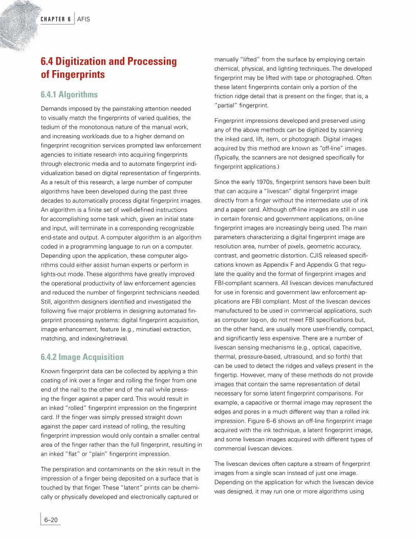
The livescan devices often capture a stream of fingerprint images from a single scan instead of just one image. Depending on the application for which the livescan device was designed, it may run one or more algorithms using
6–20
c h A p t e r 6 AFIS

FIgUrE 6–6 Fingerprint images from (a) a livescan FTIR-based optical scanner; (b) a livescan capacitive scanner; (c) a livescan piezoelectric scanner; (d) a livescan thermal scanner; (e) an off-line inked impression; (f) a latent fingerprint.
(a) (b)
(c) (d)
(e) (f)
either a resource-limited (memory and processing power) microprocessor on-board or by using an attached computer. For example, the livescan booking stations usually run an algorithm that can mosaic (stitch) multiple images acquired as a video during a single rolling of a finger on the scanner into a large rolled image. Algorithms also typically run on an integrated booking management system to provide real-time previews (graphical user interface and zoom) to assist the operator in placing or aligning fingers or palms correctly. Typically, a fingerprint image quality-checking algorithm is also run to alert the operator about the acquisition of a poor-quality fingerprint image so that a better quality image can be reacquired from the finger or palm. Typical output from such an automatic quality-checker algorithm is depicted in Figure 6–7.
Although optical scanners have the longest history and highest quality, the new solid-state sensors are gaining great popularity because of their compact size and the ease with which they can be embedded into laptop computers, cellular phones, smart pens, personal digital assistants (PDAs), and the like. Swipe sensors, where a user is required to swipe his or her finger across a livescan sensor that is wide but very short, can offer the lowest cost and size. Such sensors image a single line or just a few lines (slice) of a fingerprint, and an image-stitching algorithm is used to stitch the lines or slices to form a two-dimensional fingerprint image (Figure 6–8).
Depending on the application, it may be desirable to implement one or more of the following algorithms in the livescan device:
6–21
AFIS c h A p t e r 6

FIgUrE 6–7 (a) A good-quality fingerprint;
(b) A medium-quality fingerprint with creases; (c) A poor-quality fingerprint;
(d) A very poor-quality fingerprint containing a lot of noise.
• Automaticfinger-detectionalgorithm—Thescanner automatically keeps looking for the presence of a finger on its surface and, as soon as it determines that there is a finger present on its surface, it alerts the system.
• Automaticfingerprint-capturealgorithm—Immediately after the system has been alerted that a finger is pres-ent on the surface of the scanner, it starts receiving a series of images, and the fingerprint-capture algorithm automatically determines which frame in the image sequence has the best image quality and grabs that frame from the video for further image processing and matching.
• Vitalitydetectionalgorithm—Thescannercandetermine whether the finger is consistent with deposition by a living human being.
• Imagedata-compressionalgorithm—Compressed image will require less storage and bandwidth when transferred to the system.
• Image-processingalgorithms—Certainapplicationswill benefit from feature extraction carried out on the sensor itself; the transfer of the fingerprint features will also require less bandwidth than the image.
• Fingerprint-matchingalgorithm—Certainapplications would like the fingerprint matching to be performed on the sensor for security reasons, especially for on-board sequence checking.
• Cryptographicalgorithmsandprotocol(s)—Implemented in the scanner to carry out secure communication.
(a) Quality index = 0.9 (b) Quality index = 0.7
(c) Quality index = 0.4 (d) Quality index = 0.2
6–22
c h A p t e r 6 AFIS
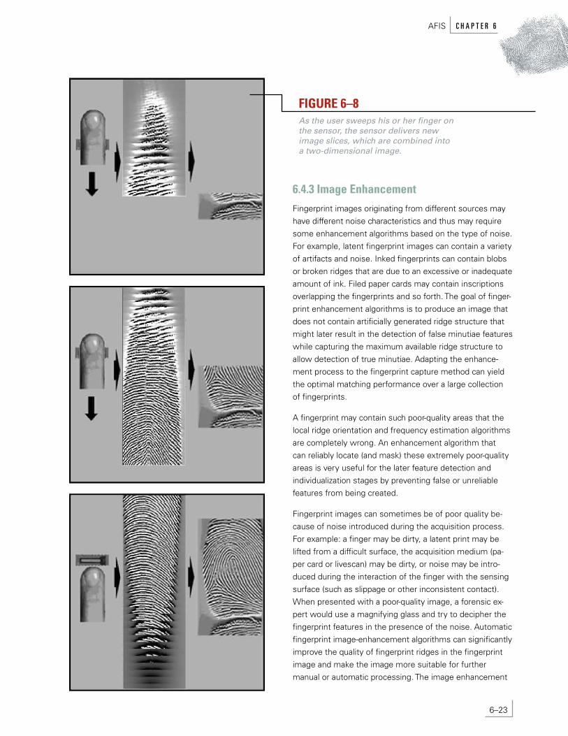
FIgUrE 6–8 As the user sweeps his or her finger on the sensor, the sensor delivers new image slices, which are combined into a two-dimensional image.
6.4.3 Image Enhancement Fingerprint images originating from different sources may have different noise characteristics and thus may require some enhancement algorithms based on the type of noise. For example, latent fingerprint images can contain a variety of artifacts and noise. Inked fingerprints can contain blobs or broken ridges that are due to an excessive or inadequate amount of ink. Filed paper cards may contain inscriptions overlapping the fingerprints and so forth. The goal of finger-print enhancement algorithms is to produce an image that does not contain artificially generated ridge structure that might later result in the detection of false minutiae features while capturing the maximum available ridge structure to allow detection of true minutiae. Adapting the enhance-ment process to the fingerprint capture method can yield the optimal matching performance over a large collection of fingerprints.
A fingerprint may contain such poor-quality areas that the local ridge orientation and frequency estimation algorithms are completely wrong. An enhancement algorithm that can reliably locate (and mask) these extremely poor-quality areas is very useful for the later feature detection and individualization stages by preventing false or unreliable features from being created.
Fingerprint images can sometimes be of poor quality be-cause of noise introduced during the acquisition process. For example: a finger may be dirty, a latent print may be lifted from a difficult surface, the acquisition medium (pa-per card or livescan) may be dirty, or noise may be intro-duced during the interaction of the finger with the sensing surface (such as slippage or other inconsistent contact). When presented with a poor-quality image, a forensic ex-pert would use a magnifying glass and try to decipher the fingerprint features in the presence of the noise. Automatic fingerprint image-enhancement algorithms can significantly improve the quality of fingerprint ridges in the fingerprint image and make the image more suitable for further manual or automatic processing. The image enhancement
6–23
AFIS c h A p t e r 6

FIgUrE 6–9 An example of
local area contrast enhancement. The
algorithm enhances the entire image by
enhancing a large number of small
square local areas.
algorithms do not add any external information to the fingerprint image. The enhancement algorithms use only the information that is already present in the fingerprint image. The enhancement algorithms can suppress various types of noise (e.g., another latent print, background color) in the fingerprint image and highlight the existing useful features. These image enhancement algorithms can be of two types.
6.4.3.1 Enhancement of Latent Prints for AFIS Searching. In the case of latent searches into the forensic AFISs, the enhancement algorithm is interactive, that is, live feedback about the enhancement is provided to the forensic expert through a graphical user interface. Through this interface, the forensic expert is able to use various algorithms to choose the region of interest in the fingerprint image, crop the image, invert color, adjust intensity, flip the image, magnify the image, resize the image window, and apply compression and decompression algorithms. The forensic expert can selectively apply many of the available enhance-ment algorithms (or select the parameters of the algorithm) based on the visual feedback. Such algorithms may include histogram equalization, image intensity rescaling, image intensity adjustments with high and low thresholds, local or global contrast enhancement, local or global background subtraction, sharpness adjustments (applying high-pass filter), background suppression (low-pass filter), gamma adjustments, brightness and contrast adjustments, and so forth. An example of local area contrast enhancement is shown in Figure 6–9. In this example, the fingerprint image enhancement algorithm enhances only a small, square, local area of the image at a time but traverses over the entire image in a raster scan fashion such that the entire image is enhanced. Subsequent fingerprint feature extrac-tion can then be either performed manually or through automatic fingerprint feature extraction algorithms.
6.4.3.2 Automated Enhancement of Fingerprint Images. In the case of lights-out applications (frequently used in automated background checks and commercial applications for control of physical access), human assistance does not occur in the fingerprint individualization process. Enhance-ment algorithms are used in the fully automated mode to improve the fingerprint ridge structures in poor-quality fingerprint images.
An example of a fully automated fingerprint image- enhancement algorithm is shown in Figure 6–10. In this example, contextual filtering is used that has a low-pass (smoothing) effect along the fingerprint ridges and a band-pass (differentiating) effect in the direction orthogonal to the ridges to increase the contrast between ridges and valleys. Often, oriented band-pass filters are used for such filtering. One such type of commonly used filters is known as Gabor filters. The local context is provided to such contextual filters in terms of local orientation and local ridge frequency.
6.4.4 Feature Extraction Local fingerprint ridge singularities, commonly known as minutiae points, have been traditionally used by forensic experts as discriminating features in fingerprint images. The most common local singularities are ridge endings and ridge bifurcations. Other types of minutiae mentioned in the literature, such as the lake, island, spur, crossover, and so forth (with the exception of dots), are simply compos-ites of ridge endings and bifurcations. Composite minutiae, made up of two to four minutiae occurring very close to each other, have also been used. In manual latent print processing, a forensic expert would visually locate the mi-nutiae in a fingerprint image and note its location, the ori-entation of the ridge on which it resides, and the minutiae
6–24
c h A p t e r 6 AFIS
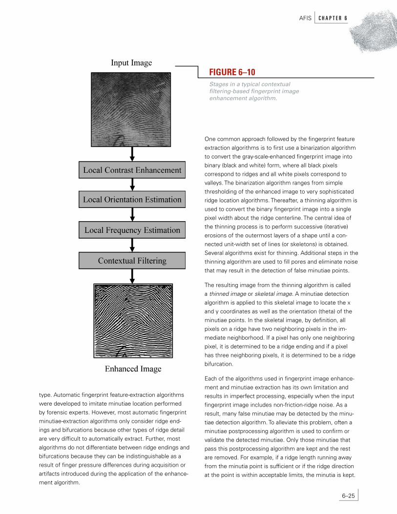
FIgUrE 6–10 Stages in a typical contextual filtering-based fingerprint image enhancement algorithm.
type. Automatic fingerprint feature-extraction algorithms were developed to imitate minutiae location performed by forensic experts. However, most automatic fingerprint minutiae-extraction algorithms only consider ridge end-ings and bifurcations because other types of ridge detail are very difficult to automatically extract. Further, most algorithms do not differentiate between ridge endings and bifurcations because they can be indistinguishable as a result of finger pressure differences during acquisition or artifacts introduced during the application of the enhance-ment algorithm.
One common approach followed by the fingerprint feature extraction algorithms is to first use a binarization algorithm to convert the gray-scale-enhanced fingerprint image into binary (black and white) form, where all black pixels correspond to ridges and all white pixels correspond to valleys. The binarization algorithm ranges from simple thresholding of the enhanced image to very sophisticated ridge location algorithms. Thereafter, a thinning algorithm is used to convert the binary fingerprint image into a single pixel width about the ridge centerline. The central idea of the thinning process is to perform successive (iterative) erosions of the outermost layers of a shape until a con-nected unit-width set of lines (or skeletons) is obtained. Several algorithms exist for thinning. Additional steps in the thinning algorithm are used to fill pores and eliminate noise that may result in the detection of false minutiae points.
The resulting image from the thinning algorithm is called a thinned image or skeletal image. A minutiae detection algorithm is applied to this skeletal image to locate the x and y coordinates as well as the orientation (theta) of the minutiae points. In the skeletal image, by definition, all pixels on a ridge have two neighboring pixels in the im-mediate neighborhood. If a pixel has only one neighboring pixel, it is determined to be a ridge ending and if a pixel has three neighboring pixels, it is determined to be a ridge bifurcation.
Each of the algorithms used in fingerprint image enhance-ment and minutiae extraction has its own limitation and results in imperfect processing, especially when the input fingerprint image includes non-friction-ridge noise. As a result, many false minutiae may be detected by the minu-tiae detection algorithm. To alleviate this problem, often a minutiae postprocessing algorithm is used to confirm or validate the detected minutiae. Only those minutiae that pass this postprocessing algorithm are kept and the rest are removed. For example, if a ridge length running away from the minutia point is sufficient or if the ridge direction at the point is within acceptable limits, the minutia is kept.
6–25
AFIS c h A p t e r 6

The postprocessing might also include an examination of the local image quality, neighboring detections, or other in-dicators of nonfingerprint structure in the area. Further, the image can be inverted in gray scale, converting white to black and black to white. Reprocessing of this inverted im-age should yield minutiae endings in place of bifurcations, and vice versa, allowing a validity check on the previously detected minutiae. The final detected minutiae are those that meet all of the validity checks. Figure 6–11 shows the steps in a typical fingerprint feature-extraction algorithm; the extracted minutiae are displayed overlapping on the input image for visualization.
Note that the stages and algorithms described in this sec-tion represent only a typical fingerprint minutiae-extraction algorithm. A wide variety of fingerprint minutiae-extraction algorithms exist and they all differ from one another, some-times in how they implement a certain stage and some-times in the stages they use and the order in which they use them. For example, some minutiae extraction algo-rithms do not use a postprocessing stage. Some others do not use a ridge-thinning stage, and the minutiae detection algorithm works directly on the result of the ridge location algorithm. Some work directly on the enhanced image, and some even work directly on the raw input image. Additional stages and algorithms may also be used.
Many other features are often also extracted in addition to minutiae. These additional features often provide useful information that can be used in the later matching stages to improve the fingerprint-matching accuracy. For example, minutiae confidence, ridge counts between minutiae, ridge count confidence, core and delta locations, local quality measures, and so forth, can be extracted. These additional features may be useful to achieve added selectivity from a minutiae-matching process. Their usefulness for this purpose may be mediated by the confidence associated with each such feature. Therefore, it is important to collect confidence data as a part of the image-enhancement and feature-extraction process to be able to properly qualify detected minutiae and associated features.
FIgUrE 6–11 Stages in a typical fingerprint
minutiae extraction algorithm.
The early fingerprint feature-extraction algorithms were developed to imitate feature extraction by forensic experts. Recently, a number of automatic fingerprint feature-extraction (and matching) algorithms have emerged that use non-minutiae-based information in the fingerprint im-ages. For example, sweat pores, which are very minute details in fingerprints, smaller than minutiae points, have been successfully extracted by algorithms from high-resolution fingerprint images. Other non-minutiae-based features are often low-level features (for example, texture
6–26
c h A p t e r 6 AFIS

features) that do not have a high-level meaning, such as a ridge ending or bifurcation. These features are well suited for machine representation and matching and can be used in place of minutiae features. Often, a combination of minutiae and non-minutiae-based features can provide the best accuracy in an automatic fingerprint individualization system. Forensic experts use such fine features implicitly, along with normal ridge endings and bifurcations features, during examination.
6.4.5 Matching Fingerprint matching can be defined as the exercise of finding the similarity or dissimilarity in any two given fin-gerprint images. Fingerprint matching can be best visual-ized by taking a paper copy of a file fingerprint image with its minutiae marked or overlaid and a transparency of a search fingerprint with its minutiae marked or overlaid. By placing the transparency of the search print over the paper copy of the file fingerprint and translating and rotating the transparency, one can locate the minutiae points that are common in both prints. From the number of common minutiae found, their closeness of fit, the quality of the fingerprint images, and any contradictory minutiae match-ing information, it is possible to assess the similarity of the two prints. Manual fingerprint matching is a very tedious task. Automatic fingerprint-matching algorithms work on the result of fingerprint feature-extraction algorithms and find the similarity or dissimilarity in any two given sets of minutiae. Automatic fingerprint matching can perform fingerprint comparisons at the rate of tens of thousands of times each second, and the results can be sorted accord-ing to the degree of similarity and combined with any other criteria that may be available to further filter the candidates, all without human intervention.
It is important to note, however, that automatic fingerprint-matching algorithms are significantly less accurate than a well-trained forensic expert. Even so, depending on the application and the fingerprint image quality, the automatic-fingerprint-matching algorithms can significantly reduce the work for forensic experts. For example, in the case of latent print matching where only a single, very poor quality partial fingerprint image is available for matching, the matching algorithm may not be very accurate. Still, the matching algorithm can return a list of candidate matches that is much smaller than the size of the database; the forensic expert then needs only to manually match a much smaller number of fingerprints. In the case of latent print
matching when the latent print is of good quality, or in the case of tenprint-to-tenprint matching in a background check application, the matching is highly accurate and requires minimal human expert involvement.
Automatic fingerprint-matching algorithms yield imperfect results because of the difficult problem posed by large intraclass variations (variability in different impressions of the same finger) present in the fingerprints. These intra-class variations arise from the following factors that vary during different acquisition of the same finger: (1) displace-ment, (2) rotation, (3) partial overlap, (4) nonlinear distortion because of pressing of the elastic three-dimensional finger onto a rigid two-dimensional imaging surface, (5) pressure, (6) skin conditions, (7) noise introduced by the imaging environment, and (8) errors introduced by the automatic feature-extraction algorithms.
A robust fingerprint-matching algorithm must be able to deal with all these intraclass variations in the various impressions of the same finger. The variations in displace-ment, rotation, and partial overlap are typically dealt with by using an alignment algorithm. The alignment algorithm should be able to correctly align the two fingerprint minutiae sets such that the corresponding or matching minutiae correspond well with each other after the alignment. Certain alignment algorithms also take into account the variability caused by nonlinear distortion. The alignment algorithm must also be able to take into consid-eration the fact that the feature extraction algorithm is imperfect and may have introduced false minutiae points and, at the same time, may have missed detecting some of the genuine minutiae points. Many fingerprint alignment algorithms exist. Some may use the core and delta points, if extracted, to align the fingerprints. Others use point pattern-matching algorithms such as Hough transform (a standard tool in pattern recognition that allows recogni-tion of global patterns in the feature space by recognition of local patterns in a transformed parameter space), relaxation, algebraic and operational research solutions, “tree pruning,” energy minimization, and so forth, to align minutiae points directly. Others use thinned ridge matching or orientation field matching to arrive at an alignment.
Once an alignment has been established, the minutiae from the two fingerprints often do not exactly overlay each other because of the small residual errors in the alignment algorithm and the nonlinear distortions. The next stage in a fingerprint minutiae-matching algorithm, which estab-lishes the minutiae in the two sets that are corresponding
6–27
AFIS c h A p t e r 6

FIgUrE 6–12 Stages in a typical fingerprint minutiae matching algorithm.
and those that are noncorresponding, is based on using some tolerances in the minutiae locations and orienta-tion to declare a correspondence. Because of noise that is introduced by skin condition, recording environment, imaging environment, and the imperfection of automatic fingerprint feature-extraction algorithms, the number of corresponding minutiae is usually found to be less than the total number of minutiae in either of the minutiae sets in the overlapping area. So, finally, a score computation algo-rithm is used to compute a matching score. The matching score essentially conveys the confidence of the fingerprint matching algorithm and can be viewed as an indication of the probability that the two fingerprints come from the same finger. The higher the matching score, the more likely it is that the fingerprints are mated (and, conversely, the lower the score, the less likely there is a match). There are many score computation algorithms that are used. They range from simple ones that count the number of matching minutiae normalized by the total number of minutiae in the two fingerprints in the overlapping area to very complex probability-theory-based, or statistical-pattern-recognition-classifier-based algorithms that take into account a number of features such as the area of overlap, the quality of the fingerprints, residual distances between the matching minutiae, the quality of individual minutiae, and so forth. Figure 6–12 depicts the steps in a typical fingerprint match-ing algorithm.
Note that the stages and algorithms described in this sec-tion represent only a typical fingerprint minutiae-matching algorithm. Many fingerprint minutiae-matching algorithms exist and they all differ from one another. As with the various extraction algorithms, matching algorithms use different implementations, different stages, and different orders of stages. For example, some minutiae-matching al-gorithms do not use an alignment stage. These algorithms instead attempt to prealign the fingerprint minutiae so that alignment is not required during the matching stage. Other algorithms attempt to avoid both the prealignment and alignment during matching by defining an intrinsic coordinate system for fingerprint minutiae. Some minutiae-matching algorithms use local alignment, some use global
alignment, and some use both local and global alignment. Finally, many new matching algorithms are totally differ-ent and are based on the non-minutiae-based features automatically extracted by the fingerprint feature-extraction algorithm, such as pores and texture features.
6.4.6 Indexing and retrieval In the previous section, the fingerprint matching problem was defined as finding the similarity in any two given fingerprints. There are many situations, such as controlling physical access within a location or affirming ownership of a legal document (such as a driver’s license), where a sin-gle match between two fingerprints may suffice. However, in a large majority of forensic and government applications, such as latent fingerprint individualization and background
6–28
c h A p t e r 6 AFIS

checks, it is required that multiple fingerprints (in fact, up to 10 fingerprints from the 10 fingers of the same person) be matched against a large number of fingerprints present in a database. In these applications, a very large amount of fin-gerprint searching and matching is needed to be performed for a single individualization. This is very time-consuming, even for automatic fingerprint-matching algorithms. So it becomes desirable (although not necessary) to use auto-matic fingerprint indexing and retrieval algorithms to make the search faster.
Traditionally, such indexing and retrieval has been per-formed manually by forensic experts through indexing of fingerprint paper cards into file cabinets based on finger-print pattern classification information as defined by a particular fingerprint classification system.
Similar to the development of the first automatic finger-print feature extraction and matching algorithms, the initial automatic fingerprint indexing algorithms were developed to imitate forensic experts. These algorithms were built to classify fingerprint images into typically five classes (e.g., left loop, right loop, whorl, arch, and tented arch) based on the many fingerprint features automatically extracted from fingerprint images. (Many algorithms used only four classes because arch and tented arch types are often dif-ficult to distinguish.)
Fingerprint pattern classification can be determined by explicitly characterizing regions of a fingerprint as belong-ing to a particular shape or through implementation of one of many possible generalized classifiers (e.g., neural networks) trained to recognize the specified patterns. The singular shapes (e.g., cores and deltas) in a fingerprint image are typically detected using algorithms based on the fingerprint orientation image. The explicit (rule-based) fingerprint classification systems first detect the fingerprint singularities (cores and deltas) and then apply a set of rules (e.g., arches and tented arches often have no cores; loops have one core and one delta; whorls have two cores and two deltas) to determine the pattern type of the fingerprint image (Figure 6–13). The most successful generalized (e.g., neural network-based) fingerprint classification systems use a combination of several different classifiers.
Such automatic fingerprint classification algorithms may be used to index all the fingerprints in the database into distinct bins (most implementations include overlapping or pattern referencing), and the submitted samples are then
compared to only the database records with the same classification (i.e., in the same bin). The use of fingerprint pattern information can be an effective means to limit the volume of data sent to the matching engine, resulting in benefits in the system response time. However, the auto-matic fingerprint classification algorithms are not perfect and result in errors in classification. These classification errors increase the errors in fingerprint individualization because the matching effort will be conducted only in a wrong bin. Depending on the application, it may be feasible to manually confirm the automatically determined finger-print class for some of the fingerprints where the auto-matic algorithm has low confidence. Even so, the explicit classification of fingerprints into just a few classes has its limitations because only a few classes are used (e.g., five), and the fingerprints occurring in nature are not equally distributed in these classes (e.g., arch and tented arch are much more rare than loops and whorls).
Many of the newer automatic fingerprint classification algorithms do not use explicit classes of fingerprints into distinct classifications but rather use a continuous clas-sification of fingerprints that is not intuitive for manual pro-cessing but is amenable to automatic search algorithms. In continuous classification, fingerprints are associated with numerical vectors summarizing their main features. These feature vectors are created through a similarity-preserving transformation, so that similar fingerprints are mapped into close points (vectors) in the multidimensional space. The retrieval is performed by matching the input fingerprint with those in the database whose corresponding vectors are close to the searched one. Spatial data structures can be used for indexing very large databases. A continuous classification approach allows the problem of exclusive membership of ambiguous fingerprints to be avoided and the system’s efficiency and accuracy to be balanced by adjusting the size of the neighborhood considered. Most of the continuous classification techniques proposed in the literature use the orientation image as an initial feature but differ in the transformation adopted to create the final vec-tors and in the distance measure.
Some other continuous indexing methods are based on fingerprint minutiae features using techniques such as geo-metric hashing. Continuous indexing algorithms can also be built using other non-minutiae-based fingerprint features such as texture features.
6–29
AFIS c h A p t e r 6

FIgUrE 6–13 The six commonly used
fingerprint classes: (a) whorl, (b) right loop, (c) arch, (d) tented arch,
(e) left loop, and (f) double loop whorl.
Choosing an indexing technique alone is usually not suf-ficient; a retrieval strategy is also usually defined according to the application requirements, such as the desired ac-curacy and efficiency, the matching algorithm used to com-pare fingerprints, the involvement of a human reviewer, and so on. In general, different strategies may be defined for the same indexing mechanism. For instance, the search may be stopped when a fixed portion of the database has been explored or as soon as a matching fingerprint is found. (In latent fingerprint individualization, a forensic ex-pert visually examines the fingerprints that are considered sufficiently similar by the minutiae matcher and terminates the search when a true correspondence is found.) If an exclusive classification technique is used for indexing, the following retrieval strategies can be used:
• Hypothesizedclassonly—Onlyfingerprintsbelonging to the class to which the input fingerprint has been as-signed are retrieved.
• Fixedsearchorder—Thesearchcontinuesuntilamatch is found or the whole database has been explored. If a correspondence is not found within the hypothesized class, the search continues in another class, and so on.
• Variablesearchorder—Thedifferentclassesarevisited according to the class likelihoods produced by the classifier for the input fingerprint. The search may be stopped as soon as a match is found or when the likeli-hood ratio between the current class and the next to be visited is less than a fixed threshold.
(a) (b)
(c) (d)
(e) (f)
6–30
c h A p t e r 6 AFIS

Finally, many system-level design choices may also be used to make the retrieval fast. For example, the search can be spread across many computers, and special- purpose hardware accelerators may be used to conduct fast fingerprint matching against a large database.
6.4.7 Accuracy Characterization Although manual fingerprint matching is a very tedious task, a well-trained forensic expert is not likely to make in-dividualization mistakes, especially when the fingerprint im-age quality is reasonable. Automatic fingerprint algorithms, on the other hand, are not nearly as accurate as forensic experts and have difficulty in dealing with the many noise sources in fingerprint images. Accuracy of fingerprint algorithms is crucial in designing fingerprint systems for real-world usage. The matching result must be reliable because many real-world decisions will be based on it. Algorithm designers usually acquire or collect their own fin-gerprint database and test the accuracy of their fingerprint algorithms on this database. By testing new algorithms or changes in the old algorithm or changes in algorithm parameters on the same database, they can know whether the new algorithm or changes improve the accuracy of the algorithm. Further, the algorithms’ developers look closely at the false-positive and false-nonmatch errors made by their algorithms and get a better understanding of the strengths and limitations of their algorithms. By comparing the errors made by different algorithms or changes, the al-gorithm designers try to understand whether a change im-proves false positives, false nonmatches, both, or neither, and why. The algorithms’ designers can then come up with algorithmic techniques to address the remaining errors and improve their algorithms’ accuracy. It is desirable to have as large a database of fingerprints as possible from as large a demography as possible so that the algorithms are not overly adjusted to any certain variety of fingerprints and the accuracy obtained in the laboratory generalizes well in the field. Public organizations (e.g., NIST) perform periodic testing of fingerprint algorithms from different vendors on a common database to judge their relative accuracy.
There is a trade-off between the false positives and false-nonmatch error rates in fingerprint matching. Either of these two errors can be lowered at the expense of increas-ing the other error. Different applications have different requirements for these two types of errors. Interestingly, different fingerprint algorithms may perform differently, depending on the error rates. For example, algorithm A
may be better than algorithm B at a low false-positive rate, but algorithm B may be better than algorithm A at a low false-nonmatch rate. In such cases, the algorithm design-ers may choose a certain algorithm or specific parameters to be used, depending on the application.
6.5 Summary Fingerprint technology has come a long way since its inception more than 100 years ago. The first primitive live- scan fingerprint readers introduced in 1988 were unwieldy beasts with many problems as compared to the sleek, inexpensive, and relatively miniscule sensors available to-day. During the past few decades, research and active use of fingerprint matching and indexing have also advanced our understanding of individuality, information in finger-prints, and efficient ways of processing this information. Increasingly inexpensive computing power, less expensive fingerprint sensors, and the demand for security, efficiency, and convenience have led to the viability of automatic fingerprint algorithms for everyday use in a large number of applications.
There are a number of challenges that remain to be over-come in designing a completely automatic and reliable fingerprint individualization system, especially when finger-print images are of poor quality. Although automatic sys-tems have improved significantly, the design of automated systems do not yet match the complex decision-making of a well-trained fingerprint expert as decisions are made to match individual fingerprints (especially latent prints). Still, automatic fingerprint matching systems hold real promise for the development of reliable, rapid, consistent, and cost-effective solutions in a number of traditional and newly emerging applications.
Research in automatic fingerprint recognition has been mostly an exercise in imitating the performance of a human fingerprint expert without access to the many underlying, information-rich features an expert is able to glean by visual examination. The lack of such a rich set of informative features in automatic systems is mostly because of the unavailability of complex modeling and image-processing techniques that can reliably and consistently extract detailed features in the presence of noise. Perhaps using the human, intuition-based manual fingerprint recognition approach may not be the most appropriate basis for the design of automatic fingerprint recognition systems. There
6–31
AFIS c h A p t e r 6

may be a need for exploring radically different features rich in discriminatory information, robust methods of fingerprint matching, and more ingenious methods for combining fingerprint matching and classification that are amenable to automation.
6.6 reviewers The reviewers critiquing this chapter were Patti Blume, Christophe Champod, Wayne Eaton, Robert J. Garrett, Lau-ra A. Hutchins, Peter D. Komarinski, and Kasey Wertheim.
6.7 references AFIS Committee Report. International Association for Identification: Mendota Heights, MN, 1994.
AFIS Committee Report. J. Forensic Ident. 1998, 48 (4), 489–500.
American National Standards for Information Systems— Data Format for the Interchange of Fingerprint Information; ANSI/NIST-CSL 1-1993; National Institute of Standards and Technology, U.S. Government Printing Office: Washington, DC, 1993.
American National Standard for Information Systems— Data Format for the Interchange of Fingerprint, Facial & SMT (Scar, Mark, and Tattoo) Information; ANSI/NIST-ITL 1a-1997; National Institute of Standards and Technology, U.S. Government Printing Office: Washington, DC, 1997.
American National Standard for Information Systems— Data Format for the Interchange of Fingerprint, Facial, & & Scar Mark & Tattoo (SMT); ANSI/NIST-ITL 1-2000, NIST Special Publication #500-245; National Institute of Stan-dards and Technology, U.S. Government Printing Office: Washington, DC, 2000.
American National Standards for Information Systems— Data Format for the Interchange of Fingerprint, Facial, & Other Biometric Information—Part 1 (Traditional Format); ANSI/NIST-ITL 1-2007, NIST Special Publication #500-271; National Institute of Standards and Technology, U.S. Gov-ernment Printing Office: Washington, DC, 2007. Available online at http://www.nist.gov/customcf/get_pdf.cfm?pub_ id=51174.
American National Standards for Information Systems— Data Format for the Interchange of Fingerprint, Facial, & Other Biometric Information—Part 2 (XML Version); ANSI/ NIST-ITL 2-2008, NIST Special Publication #500-275; Na-tional Institute of Standards and Technology, U.S. Govern-ment Printing Office: Washington, DC, 2008. Available online at http://www.nist.gov/customcf/get_pdf.cfm?pub_ id=890062.
Bruton, T. Annual Report of the Crime Scene Investigations Unit; San Francisco Police Department: San Francisco, CA, 1989.
Cole, S. Suspect Identities; Harvard University Press: Cambridge, MA, 2001.
FBI Request for Quotation No. 66-1, December 16, 1966.
Greenwood, P. W.; Chaiken, J. M.; Petersilia, J. The Criminal Investigative Process (Vols. 1–3); Technical Report R-1777-DOJ; RAND Corporation: Santa Monica, CA, 1975.
Grother, P.; McCabe, M.; et al. MINEX: Performance and Interoperability of INCITS 378 Fingerprint Template; NISTIR 7296; National Institute of Standards and Technology, March 21, 2006.
Hicklin, A.; Khanna, R. The Role of Data Quality in Biomet‑ric Systems; Mitretek Systems: Falls Church, VA, 2006.
Higgins, P. Standards for the Electronic Submission of Fingerprint Cards to the FBI. J. Forensic Ident. 1995, 45 (4), 409–418.
International Association for Identification. AFIS Directory of Users; IAI: Mendota Heights, MN, 1999.
Kiji, K. AFIS 30‑Year History. NEC Internal Corporate Report; NEC Solutions: Tokyo, Japan, 2002.
Komarinski, P. Automated Fingerprint Identification Systems. Elsevier: New York, 2005.
Moore, R. T. Automatic Fingerprint Identification Systems. In Advances in Fingerprint Technology, 1st ed.; Lee, H. C.; Gaensslen, R. E., Eds.; Elsevier, NY, 1991; pp 163–191.
Moses, K. R. Consumer’s Guide to Fingerprint Systems. Ident. News 1986, 36 (6), 5–7, 10.
National Institute for Standards and Technology. MINEX: Performance and Interoperability of INCITS 378 Fingerprint Template (NISTIR 7296); March 6, 2005.
6–32
c h A p t e r 6 AFIS

Petersilia, J. The Collection and Processing of Physical Evi‑dence; WN-9062-DOJ; RAND Corporation: Santa Monica, CA, 1975.
Wayman, J. Biometric Systems. Springer: New York, 2004.
Wegstein, J. H. A Computer Oriented Single‑Fingerprint Identification System; Technical Note 443; National Bureau of Standards, U.S. Department of Commerce: Washington, DC, 1969a.
Wegstein, J. H. A Semi‑Automated Single Fingerprint Identification System; Technical Note 481; National Bureau of Standards, U.S. Department of Commerce: Washington, DC, 1969b.
Wegstein, J. H. Automated Fingerprint Identification; Technical Note 538; National Bureau of Standards, U.S. Department of Commerce: Washington, DC, 1970.
Wegstein, J. H. The M40 Fingerprint Matcher; Technical Note 878; National Bureau of Standards, U.S. Department of Commerce: Washington, DC, 1972a.
Wegstein, J. H. Manual and Automated Fingerprint Registration; NBS Technical Note 730; National Bureau of Standards, U.S. Department of Commerce: Washington, DC, 1972b.
Wegstein, J. H. An Automated Fingerprint Identification System; NBS Special Publication 500-89; National Bureau of Standards, U.S. Department of Commerce: Washington, DC, 1982.
Wegstein, J. H.; Rafferty, J. F. The LX39 Latent Fingerprint Matcher; Special Publication 500-36; National Bureau of Standards, U.S. Department of Commerce: Washington, DC, 1978.
Wegstein, J. H.; Rafferty, J. F. The Automated Identifica-tion of Fingerprints. In Dermatoglyphics—Fifty Years Later; March of Dimes: Washington, DC, 1979.
Wegstein, J. H.; Rafferty, J. F.; Pencak, W. J. Matching Fingerprints by Computer; Technical Note 466; National Bureau of Standards, U.S. Department of Commerce: Washington, DC, 1968.
6.8 Additional Information Asai, K.; Kato, Y.; Hoshino, Y.; Kiji, K. In Automatic Finger‑print Identification. Proceedings of the SPIE-Imaging Appli-cations for Automated Industrial Inspection and Assembly, 1979; pp 49–56.
Lee, H. C.; Gaensslen, R.E., Eds. Advances in Fingerprint Technology; 2nd ed.; CRC Press: Washington, D.C., 2001.
Millard, K. In An Approach to the Automatic Retrieval of Latent Fingerprints, Proceedings of Carnahan Conference on Electronic Crime Countermeasures, Lexington, KY, 1975; pp 45–51.
Millard, K. In Development on Automatic Fingerprint Recognition, Proceedings of the Carnahan Conference on Security Technology, Zurich, Switzerland, 1983; pp 173–178.
Prabhakar, S.; Jain, A.; Maltoni, D.; Maio, D. Handbook of Fingerprint Recognition; Springer-Verlag: New York, 2003.
Ratha, N.; Bolle, R., Eds. Automated Fingerprint Recogni‑tion Systems; Springer-Verlag: New York, 2004.
Roberts, D. F. Dermatoglyphics and Human Genetics. In Dermatoglyphics—Fifty Years Later; Birth Defects Original Article Series; Wertelecki, W., Plato, C., Paul, N. W., Eds.; Alan R. Liss Inc.: New York, 1979; pp 475–494.
Thiebault, R. In Automatic Process for Automated Fingerprint Identification, Proceedings of the International Sympo-sium on Automation of Population Register Systems, 1967; pp 207–226.
Thiebault, R. An Automatic Procedure for Identifying Fingerprints. International Criminal Police Rev. 1970, 25, 2–10.
Uchida, K. Fingerprint Identification. NEC J. Advanced Technology 2005, 2 (1), 19–27.
Wayman, J.; Jain, A.; Maltoni, D.; Maio, D., Eds. Biometric Systems, Springer-Verlag: New York, 2005.
6–33
AFIS c h A p t e r 6
-