a semi-automated single fingerprint identification system. · unitedstatesdepartmentofcommerce...
TRANSCRIPT
Itetlonsd Bureau of Smdai*
Library, E-01 A*?mK ^APR IV B69
NBS TECHNICAL NOTE
481
A Semi-automated Single Fingerprint
Identification System
j-*.t»T »r e.
o
\I/)
*«*AU 0?
U.S. DEPARTMENT OF COMMERCENational Bureau of Standards


UNITED STATES DEPARTMENT OF COMMERCEMaurice H. Stans, Secretary
NATIONAL BUREAU OF STANDARDS • A. V. Astin, Director
NBS TECHNICAL NOTE 481ISSUED APRIL 1969
A Semi-automated Single Fingerprint
Identification System
J. H. Wegstein
Center for Computer Sciences and TechnologyInstitute for Applied TechnologyNational Bureau of Standards
Washington, D.C. 20234
NBS Technical Notes are designed to supplement the
Bureau's regular publications program. They provide a
means for making available scientific data that are of
transient or limited interest. Technical Notes may be
listed or referred to in the open literature.
For sale by the Superintendent of Documents, Government Printing Office
Washington, D.C, 20402 - Price 30 cents

Contents
Page
1. Introduction 1
2. Objectives of the system 2
3. Instructions for coding a fingerprint 3
4. Computer procedure for reading and filing
codes — ----- 4
5. Procedure for comparing codes 5
6. Preliminary results and discussion 6
7. Conclusion 7
3. References 8
II

A Semi- automated Single FingerprintIdentification System
by J. Ho Wegstein
A system is described in which a fingerprint ismanually coded by tracing certain ridges and noting eventssuch as ridge endings and ridge beginnings. This code is
sent by teleprinter to a central file where a computeridentifies the fingerprint by comparing the code withcodes previously entered in the file. The scheme forcomparing codes is given along with some preliminary testresults using typical fingerprints.
Key words: Computerized- fingerprint identification,fingerprints, pattern-recognition
lo Introduction
The Ninth Session of the International Police Conference held inNew York in 1923 adopted a system for identifying individuals usinginformation from single fingerprints. This system, called DistantIdentification, was developed by Hakon Jorgensen and utilized aboutfifty numerals of coded fingerprint information which could be trans-mitted by telephone, telegraph, or radio.
About the same time Scotland Yard began testing a similar systemby C.S. Collins . In both of these systems the coded information fromfingerprints was obtained with a magnifying glass using a specialreticle containing two parallel lines. In the Collins system theparallel lines were 6 mm apart and in the Jorgensen system the lineswere 4 mm apart. In addition to information about the core of thefingerprint, the codes also included topological information from theridges observed between the parallel lines of the reticle resting ata prescribed position on the fingerprint.
At Scotland Yard the Collins system was tested on a collectionincluding some 40,000 single prints representing about 4,000 persons.It was found that the codes did not discriminate adequately betweenlike and unlike prints, and it was necessary in many cases to examinenot less than 75 per cent of the impressions filed under the particulartype of pattern for which the search was being made. During a periodof seven years only a very few identifications were made .
Another single fingerprint identification system was developed byBattley4 at Scotland Yard which was intended to augment the Henrysystem for dealing with latent fingerprints found at the scene of a
crime. The Battley system deals with coded core information along withdelta positions, ridge counts, ridge traces and other peculiarities of
the printo A special reticle with concentric circles is used for defin-
ing areas for scrutiny in the fingerprint.

The success of any of these single fingerprint identification
systems has been limited, and several reasons for this might be
identified as follows: (a) Searching files of codes manually is
difficult and slow. (b) The skill required to code the fingerprints
may have limited the number of users. (c) The technique may have hadan insufficient ability to discriminate between like and unlike prints,
(d) The system lacks an adequate scheme for ordering or classifyingthe codes.
Most of the fingerprint systems developed to date utilizetopological techniques such as core pattern descriptions, ridge countsand ridge tracing. They also utilize geometrical techniques such as
measurements on the print and determining where to count ridges.
Geometrical techniques suffer from the stretching and flexing of
fingerprints, and topological techniques such as core patterndescriptions suffer from the variation in the inking of fingerprintimpressions as well as the amount of training required by the user.
Hankley and Tou have investigated purely topological coding andconcluded that it should be feasible to automatically trace ridges andtopologically code fingerprints.
The system described in this paper attempts to strike a goodbalance between the geometrical and topological techniques used. It
limits its objectives by not attempting to deal with latent prints,and most important of all, it utilizes a computer for searching a
fingerprint file and matching fingerprint codes. The use of thecomputer has permitted the code for the fingerprint to be easilywritten by an individual with limited fingerprint experience.
2, Objectives of the System
In this system it is assumed that a central computer will maintaina file consisting of the codes for two fingerprints from each of severalthousand fugitives or persons wanted by police. At some remotelocation the two appropriate fingerprints can be taken from a suspectedperson. The codes for these fingerprints can be determined in about tenminutes using a special reticle with a regular fingerprint magnifyingglass. (An opaque projector with an enlarged reticle is of courseeasier to use,) These codes are then sent to the central computer viaa directly connected remote teleprinter or by radio or telephone to anoperator at such a typewriter. The computer compares these codes withthose in the file and computes a score indicating how well these codesmatch each of those in the appropriate section of the file. If thescore is above a certain threshold value, the computer reports theprobable identity of the suspect back to the inquirer.
An enlargement of the reticle used by this system is shown inFigure 0. The horizontal lines are 13 mm apart and the radial linesare 18° apart.
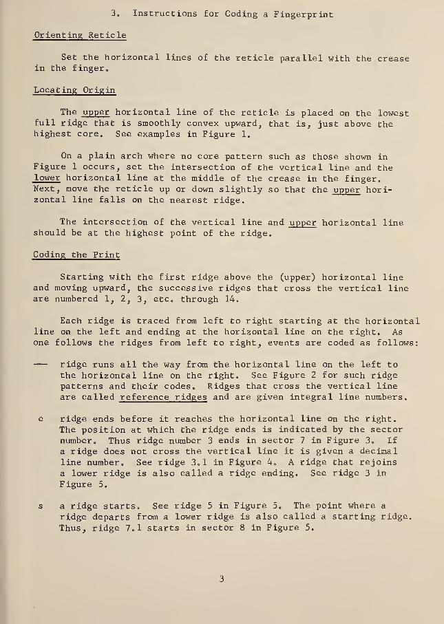
3. Instructions for Coding a Fingerprint
Orienting Reticle
Set the horizontal lines of the reticle parallel with the creasein the finger
„
Locating Origin
The upper horizontal line of the reticle is placed on the lowestfull ridge that is smoothly convex upward, that is, just above thehighest core. See examples in Figure 1.
On a plain arch where no core pattern such as those shown inFigure 1 occurs, set the intersection of the vertical line and thelower horizontal line at the middle of the crease in the finger.Next, move the reticle up or down slightly so that the upper hori-zontal line falls on the nearest ridge.
The intersection of the vertical line and upper horizontal lineshould be at the highest point of the ridge.
Coding the Print
Starting with the first ridge above the (upper) horizontal lineand moving upward, the successive ridges that cross the vertical lineare numbered 1, 2, 3, etc„ through 14.
Each ridge is traced from left to right starting at the horizontalline on the left and ending at the horizontal line on the right. Asone follows the ridges from left to right, events are coded as follows:
ridge runs all the way from the horizontal line on the left tothe horizontal line on the right. See Figure 2 for such ridgepatterns and their codes. Ridges that cross the vertical line
are called reference ridges and are given integral line numbers.
e ridge ends before it reaches the horizontal line on the right.The position at which the ridge ends is indicated by the sectornumber. Thus ridge number 3 ends in sector 7 in Figure 3o If
a ridge does not cross the vertical line it is given a decimalline number. See ridge 3»1 in Figure 4. A ridge that rejoinsa lower ridge is also called a ridge ending. See ridge 3 in
Figure 5.
s a ridge starts. See ridge 5 in Figure 5„ The point where a
ridge departs from a lower ridge is also called a starting ridge.
Thus, ridge 7» 1 starts in sector 8 in Figure 5.

i an island or short ridge whose length does not exceed a sector
length. See code line 8.1 in Figure 5.
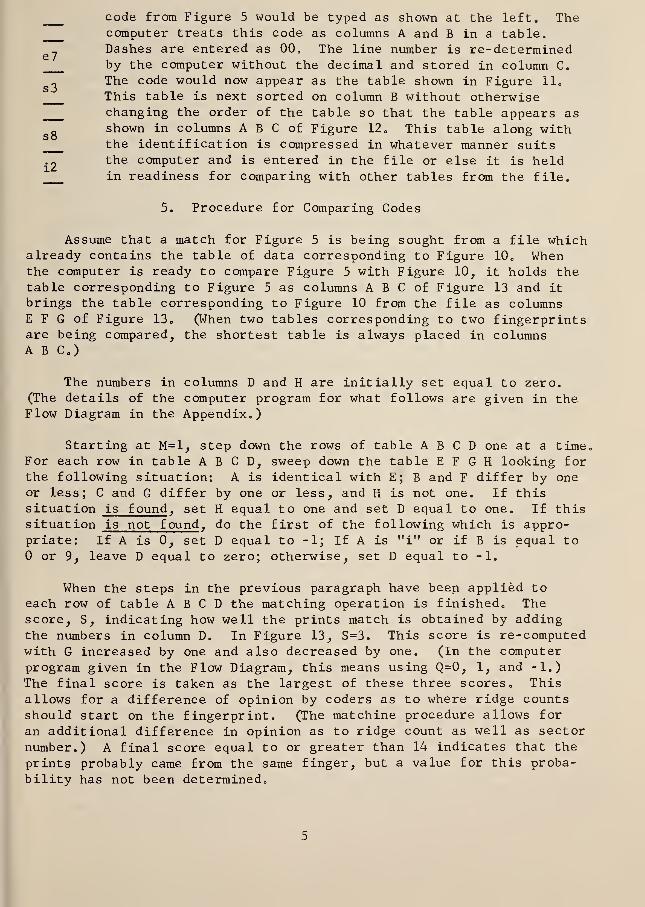
An enclosure, spur, closure between ridges, or notable lump on a
ridge is also coded as i if such event does not exceed a sector length.
Several examples are given in Figure 6„ If one of these events falls
on a sector line, such as code line 4.1 or 10.1 in Figure 6, it is
given the sector number corresponding to where it starts. The line
number of an event occurring between ridges is obtained by referring tothe next lower ridge. Note that spurs hanging below a ridge arereferred to the next lower ridge by line number. See line 7. 1 in
Figure 6„ Enclosures and spurs projecting upward are referred to theridge to which they are attached.,
A break in a ridge that is shorter than a sector length is notcoded. See ridge 5 in Figure 6. Islands separated by less than a
sector length are treated as continuous ridge. Incipient ridges areignored. When a section of ridge does not cross the horizontal line,
its start and end are both given in a code line separated by a comma.For examples, see lines 7.1 and 7.2 in Figure 7.
Figures 7 through 10 demonstrate the order in which events arecoded. Events are coded from a reference ridge outward as they arenoted in reading from left to right. Thus in Figure 8, followingridge 5, ridge 5.1 ending in e3 is followed by ridge 5.2 starting in
s7, and this is followed by 5.3 ending in el. Ridge 5.3 may bethought of as having higher rank, than 5.1 and 5.2 because it is furtherfrom the reference ridge 5.
Note that the line numbers correspond to the ridge count along thevertical line. Nothing is coded ahead of ridge 1. Coding stops whenline numbers reach 14, when an indistinct area is encountered, or whenfull ridges fail to reach from the horizontal line on the left to thehorizontal line on the right.
4. Computer Procedure for Reading and Filing Codes
When a code is to be entered into the computer the operator firstindicates whether the codes is to be filed (F) or the code is to besearched against the existing file (S) . An identification such as a
name or police identification number is next typed in followed by thecode. The line numbers are omitted to save time. As an example, the
e7
s8
12
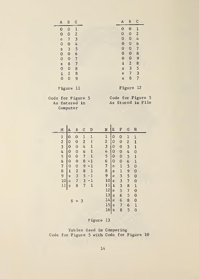
code from Figure 5 would be typed as shown at the left. Thecomputer treats this code as columns A and B in a table.Dashes are entered as 00. The line number is re-determinedby the computer without the decimal and stored in column C.
„ The code would now appear as the table shown in Figure 11.
This table is next sorted on column B without otherwisechanging the order of the table so that the table appears asshown in columns A B C of Figure 12 „ This table along withthe identification is compressed in whatever manner suitsthe computer and is entered in the file or else it is heldin readiness for comparing with other tables from the file.
5. Procedure for Comparing Codes
Assume that a match for Figure 5 is being sought from a file whichalready contains the table of data corresponding to Figure 10„ Whenthe computer is ready to compare Figure 5 with Figure 10, it holds thetable corresponding to Figure 5 as columns A B C of Figure 13 and it
brings the table corresponding to Figure 10 from the file as columnsE F G of Figure 13. (When two tables corresponding to two fingerprintsare being compared, the shortest table is always placed in columnsA B C )
The numbers in columns D and H are initially set equal to zero.(The details of the computer program for what follows are given in theFlow Diagram in the Appendix.)
Starting at M=l, step down the rows of table A B C D one at a time.For each row in table A B C D, sweep down the table E F G H looking forthe following situation: A is identical with E; B and F differ by oneor less; C and G differ by one or less, and H is not one. If thissituation is found , set H equal to one and set D equal to one. If thissituation is not found , do the first of the following which is appro-priate: If A is 0, set D equal to -1; If A is "i" or if B is equal to
or 9, leave D equal to zero; otherwise, set D equal to -1.
When the steps in the previous paragraph have been applied toeach row of table A B C D the matching operation is finished,, Thescore, S, indicating how well the prints match is obtained by addingthe numbers in column D. In Figure 13, S=3. This score is re-computedwith G increased by one and also decreased by one. (In the computerprogram given in the Flow Diagram, this means using Q=0, 1, and -1.)
The final score is taken as the largest of these three scores. Thisallows for a difference of opinion by coders as to where ridge countsshould start on the fingerprint. (The matchine procedure allows for
an additional difference in opinion as to ridge count as well as sector
number.) A final score equal to or greater than 14 indicates that the
prints probably came from the same finger, but a value for this proba-
bility has not been determined.

Figures 14 and 15 show two different impressions taken from the
same finger„ The reticle is superimposed and the code for each impres-sion is shown at the right of each figure. Note that the codes do notexactly agree. For example, the ridge ending, eo, in line 1 1 of
Figure 15 does not occur in the code in Figure 14. Also, the ridgeending, e3, in line 7.1 of Figure 15 is interpreted as being in codeline 8.1 in Figure 14. However, these differences do not lose pointsin the scoring,, The tables generated for comparing these twoimpressions are shown in Figure 16. The score, S=26, indicates a very-
high probability that the impressions are indeed from the same finger,
6. Preliminary Results and Discussion
As a preliminary test of this system, fourteen different finger-print impressions labeled Wl through W14 were coded directly from cardsand stored in the computer file. The types include ulnar loops LH,ulnar loops RH, whorl, and double loops „ Fourteen different impressionsfrom the same fingers respectively (taken from five months to eightyears later) were then coded by a different person and labeled Pithrough P14. These codes were then compared with those in the fileand the resulting scores are given in Figure 17. The scores for twoprints from the same finger appear along the diagonal. If a thresholdwere set so that any score of 14 or greater would be considered a
"make", all of the second set of fingerprint impressions would be
correctly identified except P5 which would claim to be either Wl or
its correct match, W5.
This preliminary data suggests that a single fingerprint might be
used with a suitable threshold score to locate one or more "possibilities"for an identif ication„
When plain arches are coded it is difficult to determine where to
start counting ridges because of variation in the inking of the creasein the finger which locates the lower horizontal line of the reticle,,
As above, nine different arches were coded and filed as W15 through W23„Different impressions of these same fingers were coded by another coderand searched against the file„ The results, shown in Figure 18,
indicate that single arches are not very satisfactory for use in thissystem. The very low score for P18 matched with W18 was found to be
caused by a difference of inking of the crease in the finger,,
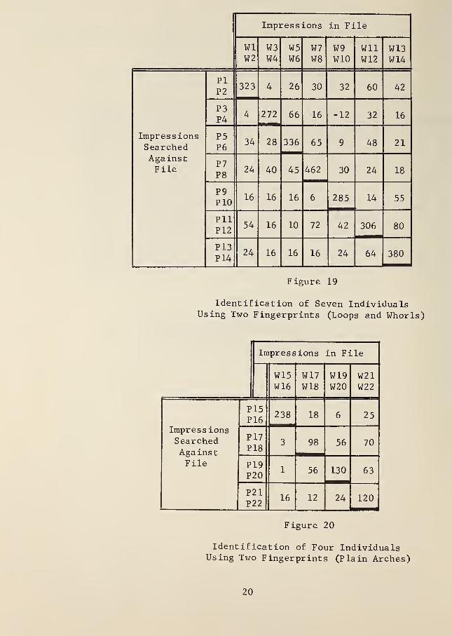
The scores in Figure 17 and 18 suggest that using two fingerprintsfrom an individual instead of one print will produce a higher discrimi-nation. To analyse this, assume that successive pairs of these printsare from the same person. Thus assume that Wl and W2 are both fromthe same person. Pi and P2 would therefore be two different impressionsfrom the same fingers of this person. The scores of Pi versus Wl equalto 19 and P2 versus W2 equal to 17 are multiplied together to producea new score for this individual, SR=323. Pi versus W3 and P2 versus W4produce a score of 4 representing a comparison of prints from twodifferent people. The results of this scoring technique for the loops

and whorls are shown in Figure 19 and the results using arches areshown in Figure 20. With a threshold score of SR=90, every individualwould be correctly identified.
7. Conclusion
From these preliminary results, it appears desirable to use twofingerprints from each person, for example the two index fingers.Arches are less reliable than other pattern types. This degradationcould be minimized by systematically skipping arches and using theprints from other fingers. If this practice were followed, archeswould only be used from those individuals who have no other typesof prints.
Considerably more fingerprints must be processed to answer thefollowing questions: What threshold score should be used? What is
the probability that an identification is correct? Can policetechnicians readily learn to consistently code fingerprints using thissystem? When an individual's prints are to be placed in the file,what is the probability that prints can be found in existing files thatare suitable for coding? (When a suspect is in custody the unsuitableprints can be re-taken.) Can a computer or specially built devicesearch a file fast enough? This raises a question as to whethersubfiles are needed based on pattern types or whether an ordering or
classification scheme can be devised based on the code themselves.Finally, will the system be useful?
The author is indebted to the Identification Division of theFederal Bureau of Investigation for its assistance and financialsupport of this work. He is indebted for the computer programmingand testing of this system to Mr J.F. Rafferty of the National Bureauof Standards and to Mr. W.J. Pencak, a Guest Worker at NBS from theFederal Bureau of Investigation.
This system was tested with the MOBIDIC computer in the NBSResearch Computer Facility. It has been particularly helpful to
demonstrate the system using a portable teletype terminal with anacoustic data coupler and a regular telephone line directly to the
computer.

8. References
1. Jorgensen, Hakon, Distant Identification andOne- finger Registration . Publications of
International Police Conference, PoliceDepartment, New York, 1923.
2. Collins, CoSo, A Telegraphic Code for FingerprintFormulae . Scotland Yard, London, 1921.
3o Battley, H. , Single Fingerprints . H.M. StationeryOffice, London, 1930. (p. 10)
4. Ibid
5. Hankley, W.J., and Tou, J.T., "AutomaticFingerprint Interpretation and Classificationvia Contextual Analysis and Topological Coding,"Pictorial Pattern Recognition . Thompson BookCompany, Washington, D.C. , 1968.

Figure 0.
Rcliclc

-m
~miqu'3 re l

fjaur& 2.
Figure 3.
Figure ¥.
o V/frf^ 1
I
-^ -
3 -
3.1 e2
Faure S.
ii
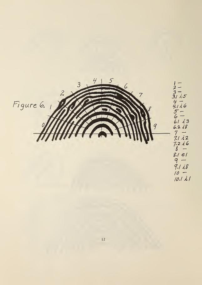
Figure &,/
12

FJ'cture JO.
13
ABC A B
1
2
e 7 3
4
s 3 5
6
7
s 8 7
8
i 2 8
9
Figure 11
Code for Figure 5
As Entered in
Computer
1
2
4
6
7
8
9
i 2 8
s 3 5
e 7 3
s 8 7
Figure 12
Code for F igure 5
As Stored in File
M A B C D N E F G H
1 1 1 1 1 1
2 2 1 2 2 1
3 4 1 3 3 1
4 6 1 4 4
5 7 1 5 5 1
6 8 -1 6 6 1
7 9 -1 7 e 1 5
8 i 2 8 1 8 s 1 9
9 s 3 5 -1 9 e 3 5
10 e 7 3 -1 10 s 3 7
11 s 8 7 1 11 i 3 8 1
12 e 5 7
13 s 6 5
S = 3 14 e 6 8
15 s 7 6 1
16 s 8 5
Figure 13
Tables Used in ComparingCode for Figure 5 with Code for Figure 10
14
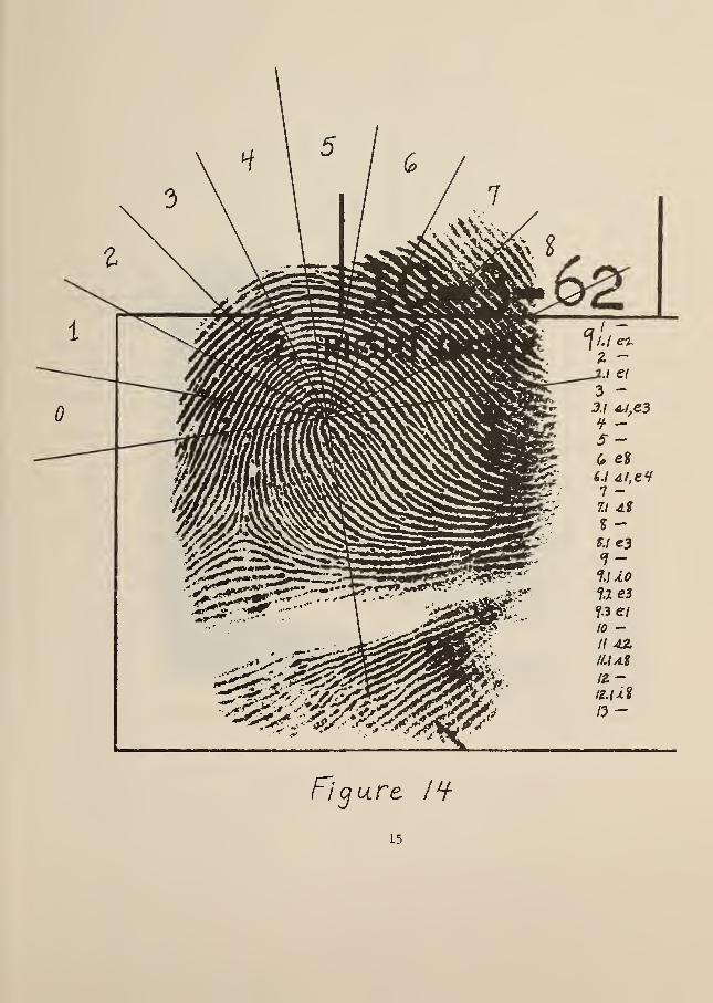
Figure l<i
15
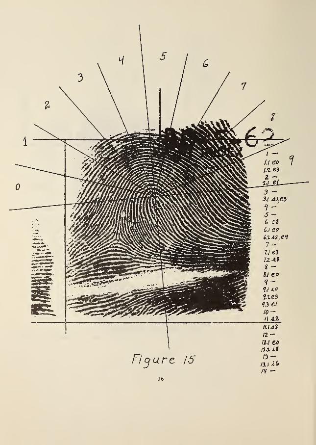
Figure 15
ll.i A%12-H.t to12.1 it
/3 —I3.\ *<*
ff-ie

From;From
F igure 14 Figure 15
A B C D E F G H
1 1 1 1
2 1 2 1
3 1 3 1
4 1 4 1
5 1 5 1
7 1 7 1
8 1 8 1
9 1 9 1
10 1 10 1
12 1 12 1
13 1 13 1
i 9 1 14
e 1 2 1 e 1 1
s 1 3 1 e 6
s 1 6 1 e 8 1
e 1 9 1 i 9 1
e 2 1 1 e 12
s 2 11 1 e 1 2 1
e 3 3 1 s 1 3 1
e 3 8 1 e 1 9
e 3 9 1 s 2 6 1
e 4 6 1 s 2 11 1
e 8 6 1 e 3 1
s 8 7 1 e 3 3 1
s 8 11 1 e 3 7 1
i 8 12 1 e 3 9 1
e 4 6 1
i 6 13
S = 26 e 8 6 1
s 8 7 1
s 8 11 1
i 8 12 1
Figur e 16
Tables Used in ComparingCode for Figure 14 with Code for Figure 15
17

Wl
I
W2
"'in^
W3
;erprint '.
W4 W5 W6
Empress ions in Fi
W7 W8 W9 W10 Wll
le
W12 W13 W14
PI 19 6 2 13 -2 5 6 4 8 10 8 7 6
P2 7 17 5 2 8 2 4 6 8 8 4 6 7 6
P3 2 6 17 8 6 6 4 8 6 8 4 5 4 6
P4 2 6 16 6 11 8 4 4 -2 2 8 6 4
Fingerprint ^5 17 8 4 6 24 4 13 7 9 6 12 8 7 12
Impressions pg 2 2 11 7 4 14 10 5 4 1 4 2 3
Against P7 * 6 4 8 5 6 22 3 5 5 4 10 9 5
File p8 8 6 8 10 5 9 6^ 21 6 6 2 6 3 2
P9 2 4 4 6 8 6 6 6 19 4 2 5 5
P10 4 8 10 4 5 2 2 1 9 15 4 7 6 11
Pll 6 12 2 2 10 3 9 2 6 4 17 10 10 12
P12 5 9 7 8 6 1 5 8 4 7 8 18
12
9 8
P13 4 10 4 6 4 8 2 4 2 8 20
8
8
P14 & 6 6 4 7 4 7 2 8 6 10 8 19
Figure 17
Scores Obtained from Comparing 14
Fingerprint Impressions with 14
Different Impressions from the SameFinger s„ The types include loops
,
whorls, and double loops
„
18

Impressions in F ile
W15 W16 W17 W18 W19 W20 W21 W22 W23
ImpressionsSearchedAgainstFile
P15 17 3 6 1 2 7 5 5 5
P16 9 14 2 3 1 3 1 5 1
P17 3 1 14 8 7 8 7 9 9
P18 4 1 10 7 6 8 5 10 10
P19 1 8 6 10 14 9 7 4
P20 4 8 7 5 13 5 7 4
P21 4 2 6 2 6 8 8 8 8
P22 6 4 7 2 7 4 7 15 9
P23 3 14 7 3 9 9 11 14
Figure 18
Scores Obtained in Comparing 9
plain Arch Impressions with 9
Different Impressions from the
Same Fingers.
19
Impressions in Fi le
WlW2
W3W4
W5W6
W7W8
W9W10
WllW12
W13W14
ImpressionsSearchedAgainstFile
PIP2
323 4 26 30 32 60 42
P3P4
4 272 66 16 -12 32 16
P5P6
34 28 336 65 9 48 21
P7P8
24 40 45 462 30 24 18
P9P10
16 16 16 6 285 14 55
PllP12
54 16 10 72 42 306 80
P13P14
24 16 16 16 24 64 380
Figure 19
Identification of Seven IndividualsUsing Two Fingerprints (Loops and Whorls)
Impressions in File
W15W16
W17W18
W19W20
W21W22
Impress ions
SearchedAgainstFile
P15P16
238 18 6 25
P17P18
3 98 56 70
P19P20
1 56 130 63
P21P22
16 12 24 120
Figure 20
Identification of Four IndividualsUsing Two Fingerprints (Plain Arches)
20

/. 2.
Appen diX
F~low X)jaarani
5=o
T=lQ=0
*r^
©
17-
A/=A1
±3,
7
H. VKHJ
( 3„-FN-,'-T )
V
f. y
II.
•57 C. W 6.1 1=
U 7*
N=N+I
-TP 10. ^
S.I Y( /V:/w) ~ >^
Q^/iD^i7- v
(h*:o)*—%12- 1
(lcM-G*-Ql:Ky+}
13. "
i^ jf
/57 E
/£
/If:
5=^5+Dai2V
= />/•*•/ ^ /*/:/u)Print
Ideni 5
ZO. i'
=7*
(j^jg )
;?/. y
23 ''
7^
Da,= ~/
-©
LonipLcher Procjrayri for AJafchlnQ nnyerprinf CoJes
ir U. S. GOVERNMENT PRINTING OFFICE: 1 969— 341 -025/1 5k 21


NBS TECHNICAL PUBLICATIONS
PERIODICALS
JOURNAL OF RESEARCH reports NationalBureau of Standards research and development in
physics, mathematics, chemistry, and engineering.
Comprehensive scientific papers give complete details
of the work, including laboratory data, experimentalprocedures, and theoretical and mathematical analy-
ses. Illustrated with photographs, drawings, andcharts.
Published in three sections, available separately:
• Physics and Chemistry
Papers of interest primarily to scientists working in
these fields. This section covers a broad range of
physical and chemical research, with major emphasison standards of physical measurement, fundamentalconstants, and properties of matter. Issued six times
a year. Annual subscription: Domestic, $6.00; for-
eign, $7.25*.
• Mathematical Sciences
Studies and compilations designed mainly for the
mathematician and theoretical physicist. Topics in
mathematical statistics, theory of experiment design,
numerical analysis, theoretical physics and chemis-
try, logical design and programming of computersand computer systems. Short numerical tables.
Issued quarterly. Annual subscription: Domestic,
$2.25; foreign, $2.75*.
• Engineering and Instrumentation
Reporting results of interest chiefly to the engineer
and the applied scientist. This section includes manyof the new developments in instrumentation resulting
from the Bureau's work in physical measurement,data processing, and development of test methods.
It will also cover some of the work in acoustics,
applied mechanics, building research, and cryogenic
engineering. Issued quarterly. Annual subscription:
Domestic, $2.75; foreign, $3.50*.
TECHNICAL NEWS BULLETIN
The best single source of information concerning
the Bureau's research, developmental, cooperative
and publication activities, this monthly publication
is designed for the industry-oriented individual whose
daily work involves intimate contact with science
and technology
—
for engineers, chemists, physicists,
research managers, product-development managers, and
company executives. Annual subscription: Domestic,
$3.00; foreign, $4.00*.
•Difference in price is due to extra cost of foreign mailing.
Order NBS publications from:
N0NPERI0DICALS
Applied Mathematics Series. Mathematicaltables, manuals, and studies.
Building Science Series. Research results, test
methods, and performance criteria of building ma-terials, components, systems, and structures.
Handbooks. Recommended codes of engineeringand industrial practice (including safety codes) de-veloped in cooperation with interested industries,
professional organizations, and regulatory bodies.
Special Publications. Proceedings of NBS con-ferences, bibliographies, annual reports, wall charts,
pamphlets, etc.
Monographs. Major contributions to the techni-
cal literature on various subjects related to the
Bureau's scientific and technical activities.
National Standard Reference Data Series.
NSRDS provides quantitative data on the physical
and chemical properties of materials, compiled from
the world's literature and critically evaluated.
Product Standards. Provide requirements for
sizes, types, quality and methods for testing variousindustrial products. These standards are developedcooperatively with interested Government and in-
dustry groups and provide the basis for commonunderstanding of product characteristics for bothbuyers and sellers. Their use is voluntary.
Technical Notes. This series consists of com-munications and reports (covering both other agencyand NBS-sponsored work) of limited or transitory
interest.
Federal Information Processing StandardsPublications. This series is the official publication
within the Federal Government for information onstandards adopted and promulgated under the Pub-lic Law 89-306, and Bureau of the Budget Circular
A-86 entitled, Standardization of Data Elementsand Codes in Data Systems.
CLEARINGHOUSE
The Clearinghouse for Federal Scientific andTechnical Information, operated by NBS, supplies
unclassified information related to Government-generated science and technology in defense, space,
atomic energy, and other national programs. Forfurther information on Clearinghouse services, write:
Clearinghouse
U.S. Department of CommerceSpringfield, Virginia 22151
Superintendent of DocumentsGovernment Printing Office
Washington, D.C. 20402

U.S. DEPARTMENT OF COMMERCEWASHINGTON, D.C. 20230
POSTAGE AND FEES PAID
U.S. DEPARTMENT OF COMMERCE
OFFICIAL BUSINESS