fingerprint recognition by minutia matching
TRANSCRIPT

FINGERPRINT RECOGNITION BY MINUTIA MATCHING
Dilruba Sharmeen Student ID: 06310047
Department of Computer Science and Engineering January 2008

ii
DECLARATION
In accordance with the requirements of the degree of Bachelor of Electronics and Communication Engineering in the Division of Computer Science and Engineering, I am presenting this thesis paper entitled, ‘FINGERPRINT RECOGNITION BY MINUTIA MATCHING’. This project has been performed under the supervisor of Dr. Tarik Ahmed Chowdhury.
I hereby declare that this thesis is based on the results found by
myself. Materials of work found by other researcher are mentioned by
reference. This thesis, neither in whole nor in part, has been previously
submitted for any degree. Signature of Signature of Supervisor Author
(Dr. Tarik Ahmed Chowdhury) (Dilruba Sharmeen)

iii
ACKNOWLEDGMENTS
At first my heartiest gratitude goes to Almighty Allah, without his
divine blessing it would not be possible for me to complete this project
successfully. To make the thesis feasible and giving the opportunity to
work on such a different and experimental project I would like to express
my great gratefulness towards my supervisor Dr. Tarik Ahmed Chowdhury
who has given me suggestion, support and assist to a great extent at all
times.
I also would like to thank all others who gave me support for the
thesis or in other aspects of my study at BRAC UNIVERSITY.
Author: Dilruba Sharmeen

iv
ABSTRACT
In this thesis a current technique for fingerprint recognition has
been investigated. It includes image preprocessing, feature extraction,
post processing and feature match. For each sub-task some methods like-
Image enhancement, image binarization, image segmentation and some
morphological operations has analyzed. Based on the analysis, an
integrated solution for fingerprint recognition is developed for
demonstration.
The demonstration program has coded using MATLAB 7.1. The
performances have shown by experiments conducted upon a variety of
fingerprint images. Also, the experiments illustrate the key issues of
fingerprint recognition that are consistent with this conversation.

v
TABLE OF CONTENTS
Title Page
Declaration ii
Acknowledgements iii
Abstract iv
Table of Contents v- vi
List of Tables vii
List of Figure viii
Chapter 1 1
1.0 Introduction 1
1.1 Introduction to Biometrics 1
1.1.1 Biometric System 1
1.1.2 Why Fingerprints are so Good for use in Biometrics? 2-3
1.2. Introduction to Fingerprints 4
1.2.1 What is a Fingerprint? 4
1.3 Fingerprint Patterns 6
1.4 What is Fingerprint Recognition? 7
1.4.1 What is the scheme to avoid False Rejection in a Fingerprint Authentication? 9
1.4.2 How do wounds affect Fingerprint Recognition? 9
1.5 Three Approaches for fingerprint Recognition 9
Chapter 2
2.0 Minutia based other Techniques 12
2.1 Direct gray-Scale Minutia Extraction 12
2.2 Minutia Matching with Pre-Alignment 13-14
2.3 Minutia Matching Avoiding Alignment 15
Chapter 3
3.0 System Design 16
3.1 System Level Design 16
3.1.1 Fingerprint Sensing and Storage 16-17
3.1.2 Which type of Sensor is the best? 18
3.2 Algorithm Level Design 18

vi
Chapter 4
4.0 Fingerprint Image Pre-Processing 21
4.1 Fingerprint Image Enhancement 21-25
4.2 Fingerprint Image Binarization 25-26
4.3 Fingerprint Image Segmentation 26
4.3.1 Morpholpgy 27
Chapter 5
5.0 Minutia Extraction 28
4.1 4. 5.1 Fingerprint Ridge Thinning 28
5.2 Connected Component-Labeling 29
5.3 Minutia Marking 30
5.4 Average Inter Ridge Width 31
Chapter 6
6.0 Fingerprint Image Post-Processing 32
6.1 False Minutia Removal 32-36
6.2 Unify Minutia Representation Feature Vectors 36
Chapter 7
7.0 Minutia Match 39
7.1 Match Period 39
7.1.1 Alignment Stage 39-41
66.1.2 7.1.2 Match Stage 42
Chapter 8
8.0 Performance Measurement 43-44
8.1 Experimentation Results 45
8.1.1 Evaluation for Changed Images 45-47
8.1.2 Evaluation for Different Images 47-49
Chapter 9
9.0 Conclusion 50
9.1 Future Work 50
References
51

vii
LIST OF TABLES Table Page Table1: Match results of Changed Images………………………… 46-47
Table2: Match results of Different Images…………………………. 48

viii
LIST OF FIGURES
No of FIGURES
Figure- 1.1.1 02
Figure- 1.2.1 04
Figure- 1.2.2 06
Figure- 1.2.3 06
Figure- 1.3.1 07
Figure- 1.4.0 07
Figure- 2.1.1 12
Figure- 2.1.2 13
Figure- 3.1.0 16
Figure- 3.1.1 17
Figure- 3.2.1 19
Figure- 3.2.2 19
Figure- 4.1.1 22
Figure- 4.1.2 23
Figure- 4.1.3 24
Figure- 4.2.1 26
Figure- 4.3.1 27
Figure- 5.1.1 28
Figure- 5.2.1 30
Figure- 5.3.1 31
Figure- 5.3.2 31
Figure- 6.1.1 33
Figure- 6.1.2 33
Figure- 6.1.3 35
Figure- 6.1.4 36
Figure- 6.2.1 37
Figure- 6.2.2 38
Figure- 8.1.1 45
Figure- 8.2.1 47
Page No
1
1.0 INTRODUCTION 1.1 INTRODUCTION to BIOMETRICS: 1.1.1 Biometric System:
Positive identification of individuals is crucial societal requirement. Until
recently, automatic personal identification technologies followed two approaches:
i) a token based approach and ii) a knowledge based approach. Token based
approaches are based on identification using tokens such as a magnetic swipe
card, key, driver’s license, etc. knowledge-based approaches use passwords and
personal identification numbers (PINs) to identify or validate a person’s identify.
Both these forms of identification are not secure, because this credential’s can be
lost, stolen or duplicated. On the other hand, biometrics is a science of verifying
and establishing the identity of an individual through physiological features or
behavioral characteristics that are unique to that individual and hence cannot be
stolen, lost or misused. The word “Biometric” is derived from the Ancient Greek
language where “Bio” means “life “and “Metric” means “To measure”. All Biometric
systems compare a biometric sample against a previously stored template to
determine a level of similarity. Biometric identification works on the principle of a
threshold. Because, it is nearly impossible to capture the biometric the same way
every time it is used for access. Therefore, the system cannot expect a 100%
match. Instead, a threshold system is used that can be modified depending on the
security level of the applications. If the score exceeds the threshold, the result is a
match and if the score falls below the threshold, the result is non-match.

2
Biometric characteristics can be divided in to two main classes, as represented in
the following figure [1.1.1]:
Fig 1.1.1: Classification of Biometrics
• Physiological Biometrics: These characteristics are related to the structure of the body, such as,
sdsdsdFingerprint, face, Irish, Hand geometry, DNA, etc.
• Behavioral Biometrics: These characteristics are related to the behavior of a person, such as,
aaaawHandwriting, Voice, Gait, Signature, keystroke, etc. [1] [2]
1.1.2 Why Fingerprints are so Good for use in Biometrics? There are many criteria that must be accounted before a physical or
behavioral trait can be considered suitable for use in biometrics. Perhaps the most
important criteria are “Uniqueness” and “Permanence”. Fingerprints have been well
proven on both counts.
• Uniqueness:
Uniqueness of fingerprint is not an established fact but an empirical
observation. Fingerprints have been routinely compared worldwide for more than

3
140 years. In that time, no two fingerprints on any two persons have been found to
be identical. Even identical twins who shared same DNA structure have different
finger prints; they tend to have fingerprints that are similar globally, i.e. have the
same fingerprint classes (e.g.. whorl, loop, arch, etc) but ridge structures are very
different. The true is also holds for the right and left finger and can be anticipated
for clones. [1] [2] [5]
• Permanence:
Fingerprints are fully formed at about seven months of fetus development
and finger ridge configuration do not change throughout the life of an individual
except due to accidents such as bruises and deep physical injuries. They simply
expand proportionately in all directions as we grow, means fingerprints maintains a
proportional scale for its entire existence. [2] [6]
The other advantages of fingerprints as a biometric are stated bellow: [8]
• High Universality: Within human population every individual has fingerprint which can be easily
aaaaaused for their authentication.
• High Indispensability: Like token-based authentications fingerprints for human identification does
not lead problems of being stolen or lost. On the other hand fingerprints would
never be forgotten like PINs, password, or other knowledge-based systems.
Actually in most cases, fingerprints would accompany the individual throughout
his/her life time unless there is some serious injury to their fingers.
• High Collectability: Fingerprints can be easily collected compared to other biometric samples,
such as Retina, DNA, Irish, etc. which require complete cooperation and high cost
special equipment to acquire the biometric samples. On the other hand the process
of fingerprint acquiring requires minimal or no user training and can be collected
easily from both cooperative and non cooperative users.

4
• Good Storability: The database of fingerprints does not require huge space; it depends on
the representation of the templates that can be chosen for the system. Depending
on the application and way of representation the size of these templates can be
from 52 bytes to several megabytes.
• High Performance: Fingerprints remain one of the most accurate biometric modalities
considering both False Accept Rate (FAR) and False Reject Rate (FRR).
• Wide Acceptability: Since the beginning of the twentieth century, fingerprints have been formally
accepted as valid personal identification trait and have become a standard routine
in forensics.
1.2 INTRODUCTION to FINGERPRINT:
1.2.1 What is a FINGERPRINT?
A fingerprint is an impression of the friction ridges found on the inner surface
of a finger or thumb. Fig [1.2.1] Finger skin is made of friction ridges, with pores
(sweat glands). Friction ridges are created during foetal live and only the general
shape is genetically defined.
Figure1.2.1: A fingerprint image labeled with different components.

5
A fingerprint is composed of different types of components [8]. Those are stated
bellow-
• Ridges: The lines that flow in various patterns across fingerprints are called
‘Ridges’.
• Furrows: The spaces between ridges are called ‘Furrows’ or ‘valleys’. It dos
not make contact with a surface under normal touch.
• Termination: The point on a fingerprint that a friction ridge begins or ends
without splitting into two or more continuing ridges or it is the immediate
ending of a ridge, at which a ridge terminates.
• Bifurcation: It is the point on the ridge from which two branches derive.
Bifurcation is also known as ‘Ridge Branch’.
• Dots: They are very small ridges.
• Islands: Ridges those are slightly longer than dots, occupying a middle
space between two temporarily divergent ridges.
• Ponds or lakes: A notch protruding from a ridge.
• Bridges: Small ridges joining two longer adjacent ridges.
• Crossover: Two ridges which crosses each other.
• Core: The core is the inner point, normally in the middle of the print, around
which swirls, loops, arches center.
• Delta: Deltas are the points, normally at the lower left or right hand of the
fingerprint, at which a triangular series of ridges center.
However, shown by intensive research on fingerprint recognition fingerprints are
distinguished by ‘MINUTIA’, which are some abnormal points or the discontinuities
of the ridges. There are among 150 different types of minutiae categorized based
on their configuration. [Fig1.2.2]
6
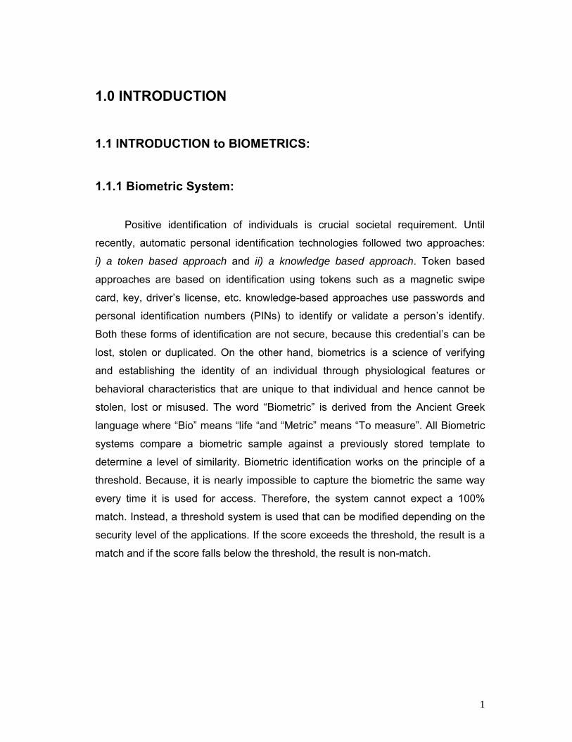
Fig1.2.2: Some of the common minutiae types
Among these minutia types ‘Termination or Ridge Ending’ and ‘Bifurcation’ are
mostly significant and have heavy usage [Fig1.2.3]. There are features that can be
used for matching such as core, delta, pores but they are not available on all
fingerprints beside requires higher resolution scanner and very good image quality.
Whereas, minutia is relatively stable and robust to contrast, image resolutions and
global distortion compared to other representations. However, to extract the
minutia from a poor quality image is not an easy task. [1][2]
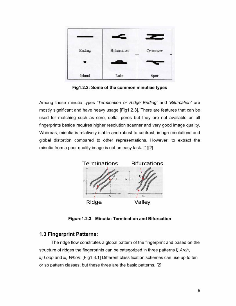
Figure1.2.3: Minutia: Termination and Bifurcation
1.3 Fingerprint Patterns: The ridge flow constitutes a global pattern of the fingerprint and based on the
structure of ridges the fingerprints can be categorized in three patterns i) Arch,
ii) Loop and iii) Whorl. [Fig1.3.1] Different classification schemes can use up to ten
or so pattern classes, but these three are the basic patterns. [2]
7
:
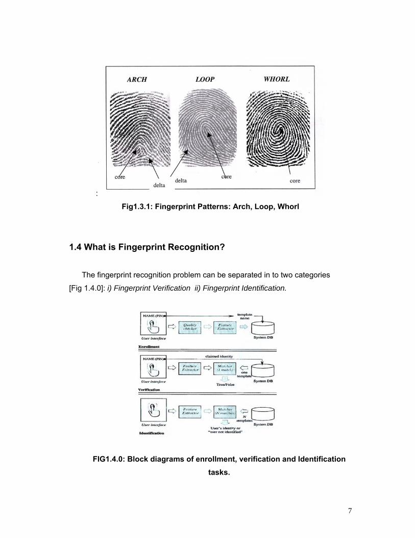
Fig1.3.1: Fingerprint Patterns: Arch, Loop, Whorl
1.4 What is Fingerprint Recognition?
The fingerprint recognition problem can be separated in to two categories
[Fig 1.4.0]: i) Fingerprint Verification ii) Fingerprint Identification.
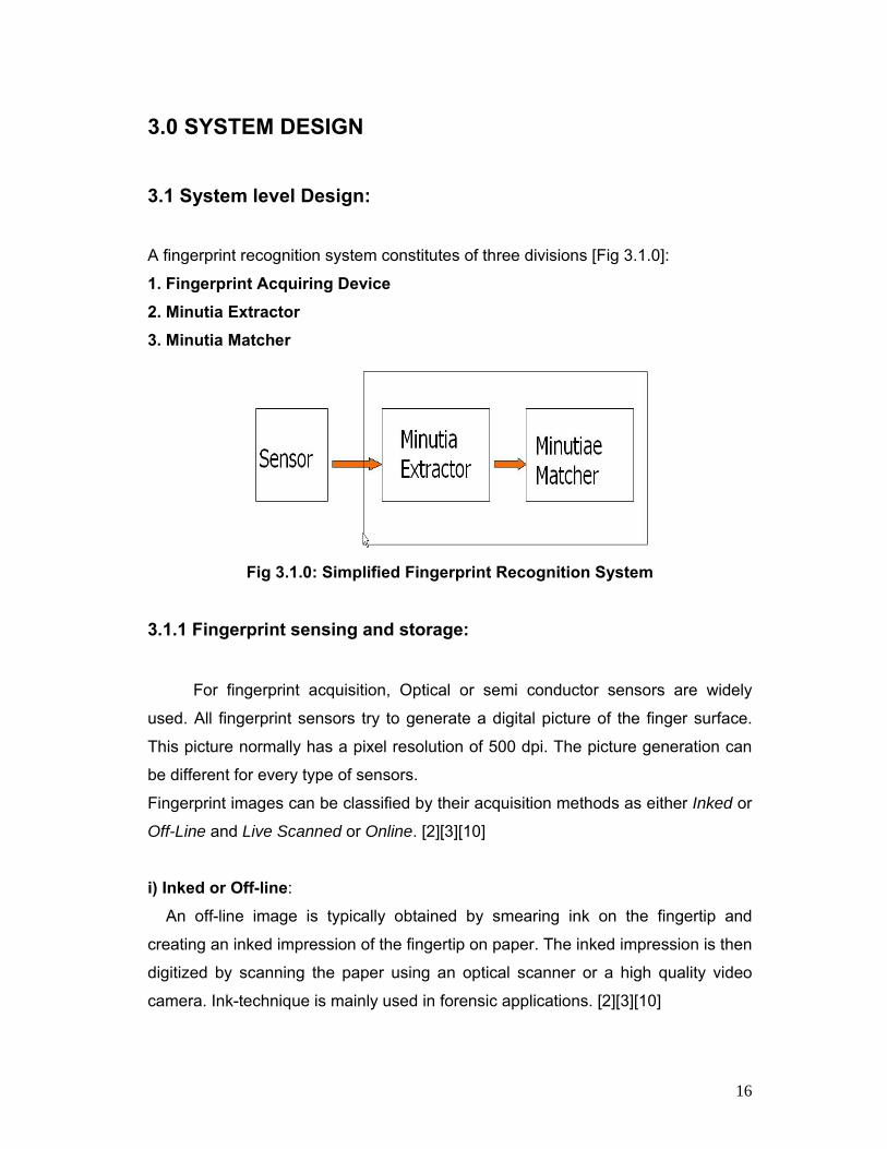
FIG1.4.0: Block diagrams of enrollment, verification and Identification tasks.

8
• Fingerprint Verification: It is the comparison of a claimant fingerprint against an enrollee fingerprint,
where the intention is that the claimant fingerprint matches the enrollee fingerprint.
A verification system either rejects or accepts the submitted claim or identity (Am I
whom I claim I am?) .To prepare for verification, a person initially enrolls his or her
fingerprint into the verification system. A representation of that fingerprint is stored
in some compressed format along with the person’s name or other identity.
Subsequently, each access is authenticated by the person identifying him or
herself, then applying the fingerprint to the system such that the identity can be
verified. Verification is also termed ‘one-to-one matching’. It is suitable for used in
civilian applications like, PC access, credit cards, personal identification,
etc.[1][3][6]
• Fingerprint Identification: Fingerprint Identification is to specify one person’s identity by his fingerprint.
(Who am I?). Without any information of the person’s identity, the fingerprint
Identification system tries to match his fingerprint with those in the whole fingerprint
database. It is especially useful for criminal investigation cases. Identification is
also termed as ‘one-to-many matching’.
There is an informal third type of matching that is termed ‘one-to-few matching’.
This is for the practical application where a fingerprint system is used by ‘a few’
users, such as by family members to enter their house. A number that constitutes
‘few’ is usually accepted to be somewhere between 5 and 20.
However, all fingerprint recognition problems are ultimately based on a well
representation of a ‘one-to-one matching’. As long as the representation of
fingerprints remains the uniqueness and keeps simple, the fingerprint matching is
straightforward and easy. [3][6]

9
1.4.1 What is the scheme to avoid False Rejection in a Fingerprint Authentication System?
The finger should be clean that means free of sticky residue and greases and
depending on the sensor should not be too damp or too dry. The finger should
always be applied on the sensor in the same manner (same position and direction)
and with uniform pressure (e.g., avoid pressuring while twisting) [5]
1.4.2 How do Wounds affect Fingerprint Recognition?
If a wound is not too deep, the finger lines will fully regenerate to their original
state. Deep cuts leave line forming scars and should be recognized as such by
good identification algorithms, thereby barely impairing the identification
performance. Most system offers the possibility to record a ‘Substitute Finger’ in
enrollment, so that a fingerprint authentication can still take place during healing
process. [6]
1.5 Three Approaches for Fingerprint Recognition: The large number of approaches to fingerprint matching can be coarsely
classified into three families.
i) Minutiae- based Matching: This is the most popular and widely used technique, being the basis of the
fingerprint comparison made by fingerprint examiners. This approach represents
the fingerprint by its local features. Each Minutia may be described by a number of
attributes, including its location in the fingerprint image, orientation, type (e.g., ridge
termination or ridge bifurcation ), a weight based on the quality of the fingerprint
image in the neighborhood of the minutia and so on. Minutiae are extracted from
the two fingerprints and stored as sets of points in the two dimensional plane.
Minutiae based matching essentially consists of finding the alignment between the
template (the representation of fingerprint acquired during enrollment is denoted as

10
TEMPLATE) and the input (the representation of fingerprint to be matched is
denoted as INPUT) minutia sets that results in the maximum number of minutiae
pairings.
Minutia based fingerprint representation and matching are widely used by both
machine and human experts because of several advantages compared to other
fingerprint representations. Such as, its configuration is highly distinctive and
minutiae based systems are more accurate than correlation based systems and the
template size of minutia based fingerprint representation is small. Minutia based
fingerprint representation also has an advantage in helping privacy issues, since
one cannot reconstruct the original image from using only minutiae information. As
the minutia are predominantly randotypic in nature and cause most of the
uniqueness in a fingerprint, therefore either directly or indirectly almost all
fingerprint system examines minutia. But, reliably extracting minutia from poor
quality fingerprints is very difficult and minutiae extraction is also time consuming.
Because of the advantages of minutia based fingerprint matching and as it is the
backbone of the current available fingerprint recognition products, in this thesis
‘Minutia-based matching’ was applied. [1][2][3]
ii) Correlation-based matching: In this approach two fingerprint images are superimposed and the correlation
between corresponding pixels is computed for different alignments (e.g., various
displacements and rotations). This approach is computationally very expensive and
also complex. [1]
ii) Ridge Feature-based Matching: The other features of the fingerprint ridge patterns e.g., local orientation and
frequency, ridge shape, texture information can be extracted more reliably than
minutiae but their distinctiveness is generally lower. The approaches belonging to
this family compare fingerprint in terms of features extracted from the ridge pattern.
In principle, correlation and minutiae-based matching could be conceived as
subfamilies of ridge feature-based matching, inasmuch as the pixel intensity and
the minutiae positions are themselves features of the finger ridge pattern. [1]

11
In this Thesis, Chapter Two will review different techniques for Fingerprint
Recognition methods. Chapter Three analyze the system design for fingerprint
recognition process. Chapter Four will discuss the Fingerprint Image Pre-
processing stage. Chapter Five will discuss different steps for Minutia Extraction.
Chapter Six examine the Fingerprint Image Post-processing stage. Chapter Seven
will evaluate the Minutia Match stages. Chapter Eight will analyze the performance
measurement and the experimentation results. Finally, thesis will be concluded in
Chapter Nine.

12
2.0 Minutia-based other Techniques 2.1 Direct Gray-Scale Minutiae Extraction: Approaches that directly work on gray-scale images to extract are
proposed to overcome some of the problems caused by fingerprint
binarization and thinning. Most of these algorithms are based on ridge tracing.
Given a starting point (xo, yo) and a direction θ0, the method of Maio et al.
tracks the ridges in the gray scale image by sailing according to the local
orientation of the ridge pattern.
Fig 2.1.1: Minutiae are located in the contours by looking for significant turns. A ridge ending is detected when there is a sharp left turn; whereas the ridge bifurcation is detected by a sharp right turn
The algorithm computes the next ridge point (xt, yt) by moving µ pixels on the
direction θ0. Since (xt, yt) is only an approximation the method then analyze
the gray-scale profile of the section set Ω (whose direction is orthogonal to θ0,
length is (2þ+1) and the median is (xt, yt) and uses the local maxima on Ω as
the new starting point (x1, y1) and the local ridge direction at (x1, y1) as the
new start direction of the next iteration. The parameters µ and þ are
determined according to the average ridge width. The tracing is extracted in

13
the direction of a ridge and stop when a ridge comes to the end or intersects
with other ridges. [2]
(a) (b (c) Fig 2.1.2: (a) Original Image; (b) the contour representation of the image;
(c) detected minutiae superimposed on the contour image. [2]
2.2 Minutiae Matching with Pre-Alignment:
Embedding fingerprint alignment in to the minutia matching stage
certainly leads to the design of robust algorithms, which are often able to
operate with noisy and incomplete data. On the other hand, the computational
complexity of such methods does not provide a high a matching throughput.
Storing pre-alignment templates in the database and pre-aligning the input
before the minutia matching can be a valid solution to speed up the 1: N
identification. In theory, if a perfect pre-alignment could be achieved, the
minutia matching could be reduced to a simple pairings. [1]

14
Two main approaches for pre-aligning have been investigated.
i) Absolute Pre-Alignment: In this process, before storing in the database each fingerprint template is
pre-aligned, independently of the others. Matching an input fingerprint I with a
set of templates requires I to be independently registered just once, and the
resulting aligned representation to be matched with all the templates. The
most common absolute pre-alignment technique translates the fingerprint
according to the position of the core point. Unfortunately, reliable detection of
the core is very difficult in noisy images in arch type patterns, and a
registration error at this level is likely to result in matching error. Absolute Pre-
alignment with respect to rotation is even more critical; some authors
proposed using the shape of the external fingerprint silhouette (if available),
the orientation of the core delta segment (if delta exists), the average
orientation in some regions around the core or the orientation of the
singularities. In any case, no definite solution has been proposed for a reliable
pre-alignment to date and, therefore, the design of a robust system requires
the minutiae matcher to tolerate pre-alignment errors to some extent. [1]
ii) Relative Pre-Alignment: The input fingerprint I has to be pre-aligned with respect to each template
T in the database; 1: N identification requires N independent pre-alignments.
Relative pre-alignment may determine a significant speed up with respect to
the algorithms that do not perform any pre-alignment, but cannot complete in
terms of efficiency with absolute pre-alignment. However, relative pre-
alignment is in general more effective (in terms of accuracy) than absolute
pre-alignment, because the features of the template T may be used to drive
the registration process. [1]

15
2.3 Minutiae Matching Avoiding Alignment:
Fingerprint alignment is certainly a critical and time-consuming step. To
overcome problems involved in alignment, and to better cope with local
distortion, some authors perform minutia matching locally. A few other
attempts have been proposed that try to globally match minutia without
requiring explicit recovery of the parameters of the transformation. Bazen and
Gerez introduced in Intrinsic Coordinate System (ICS) whose axes run along
hypothetical lines defined by the local orientation of the fingerprint patterns.
First, the fingerprint is partitioned in regular regions (i.e, regions that do not
contain singular points). In each regular region, The ICS is defined by the
orientation field. When using intrinsic coordinates instead of pixels
coordinates, minutiae are defined with respect to their position in the
orientation field. Translation, displacement and distortion move minutiae with
the orientation field they are immersed in and therefore do not change their
intrinsic coordinates. On the other hand, some practical problems such as
reliably partitioning the fingerprint in the regular regions and unambiguously
defining intrinsic coordinate axes in low-quality fingerprint images still remains
to be solved.[1]
16
3.0 SYSTEM DESIGN
3.1 System level Design:
A fingerprint recognition system constitutes of three divisions [Fig 3.1.0]:
1. Fingerprint Acquiring Device 2. Minutia Extractor 3. Minutia Matcher
Fig 3.1.0: Simplified Fingerprint Recognition System
3.1.1 Fingerprint sensing and storage: For fingerprint acquisition, Optical or semi conductor sensors are widely
used. All fingerprint sensors try to generate a digital picture of the finger surface.
This picture normally has a pixel resolution of 500 dpi. The picture generation can
be different for every type of sensors.
Fingerprint images can be classified by their acquisition methods as either Inked or
Off-Line and Live Scanned or Online. [2][3][10]
i) Inked or Off-line:
An off-line image is typically obtained by smearing ink on the fingertip and
creating an inked impression of the fingertip on paper. The inked impression is then
digitized by scanning the paper using an optical scanner or a high quality video
camera. Ink-technique is mainly used in forensic applications. [2][3][10]

17
ii) Live scanned or Online: A Live-scan image is acquired by sensing the tip of the finger directly, using a
sensor that is capable of digitizing the fingerprint on contact. Live-scan technology
is one of the main contributions to the extraordinary progress of fingerprint
recognition. [Fig 3.1.1] Especially the invention of user friendly, low-cost, reliable
and compact fingerprint scanners, which makes fingerprint recognition
technologies rapidly expand into civilian applications. Live-scan fingerprint
scanners can be classified as Optical sensors, capacitive sensors, Ultrasound
Sensors, Thermal Sensors. They have high efficiency and acceptable accuracy
except for some cases that the user’s finger is too dirty or dry.
There are other types of sensors that utilize other techniques such as high-quality
cameras, electric field or piezoelectric materials exist but are not mature enough for
large scale applications. [2][3][10]
Fig 3.1.1: Some Modern Live Scanner

18
3.1.2 Which type of sensor is the best?
This question unfortunately offers no definite answer, as every application
has different requirements and each type of sensor has its specific advantages and
also disadvantages. The following criteria can assist in reaching an answer [6]:
Cost
Degree of maturity
Image quality in sub optimal conditions
o Indoor/outdoor
o Personal/public
o Normal/abnormal fingers
o Dry/moist fingers
Size, the size of fingerprint generally determines the cost of a sensor.
Sensitivity against vandalism
Temperature resistance
Sensitivity against forgery
ESD (electrostatic discharge) Sensitivity
However, the testing database for this thesis was collected from the fingerprints
provided by FVC2002 (Fingerprint Verification Competition 2002). So, no sensing
stage has implemented.
3.2 Algorithm level Design:
To implement a minutia extractor, three-stage approaches have applied in this
thesis [Fig 3.2.1]. They are:
i) Pre-Processing
ii) Minutia Extraction iii) Post-Processing

19
Fig 3.2.1: Minutia Extractor
For the fingerprint image pre-processing stage, Histogram Equalization and
Fourier Transformation has applied for image enhancement. Minutia
extraction algorithm are of two types i) Binarized-based extraction and
ii) Gray-Scale based extraction. In this thesis Binarized-based extraction has
applied and the fingerprint image was Binarized by using the locally adaptive
threshold method [8].Region of Interest extraction and Thinning was done by
applying some Morphological operations. For post-processing stage a novel
representation for bifurcation has used to unify and Terminations and
Bifurcations.
Fig 3.2.2: Minutia Matcher
Minutia Matcher
o Alignment Stage o Match Stage

20
The Minutia matcher chooses any two minutiae as a reference minutia pair
and then matches their associated ridges first. If the ridges match well, two
fingerprint images are aligned and matching is conducted for all remaining
minutia. [Fig 3.2.2]

21
4.0 FINGERPRINT IMAGE PRE-PROCESSING
4.1 Fingerprint Image Enhancement:
A fingerprint image is one of the nosiest of image types. This is due to
predominantly to the fact that fingers are our direct form of contact for most of
the manual tasks we perform, finger tips become dirty, cuts, creased, dry, wet,
and worn, etc and also the fingerprint images acquired by from sensors or
other medias are not assured perfect quality. But fingerprint image quality is
an important factor in the performance of minutiae extraction and matching
algorithms. A good quality fingerprint image has high contrast between ridges
and furrows whereas a poor quality fingerprint image is low contrast, smudgy,
causing spurious and missing minutiae. The goal of fingerprint Image
enhancement is to reduce these noises and to improve the clarity of the ridge
structure in a fingerprint. It also connects the false broken points of ridges due
to insufficient amount of ink which is very useful for higher accuracy to
fingerprint recognition. [2][3]
General purposes of mage enhancement techniques are not very useful due
to the non-stationary nature of a fingerprint image. However, techniques such
as Gray-Level Smoothing, Contrast Stretching, Histogram Equalization,
Fourier Transform and Wiener filtering can be used for pre-processing steps.
[2]
Two methods have adopted in this thesis for Fingerprint Image enhancement:
1. Histogram Equalization 2. Fourier Transformation
22
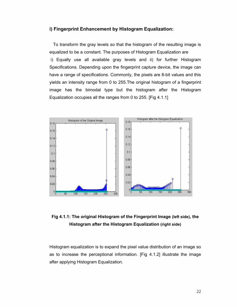
i) Fingerprint Enhancement by Histogram Equalization: To transform the gray levels so that the histogram of the resulting image is
equalized to be a constant. The purposes of Histogram Equalization are
i) Equally use all available gray levels and ii) for further Histogram
Specifications. Depending upon the fingerprint capture device, the image can
have a range of specifications. Commonly, the pixels are 8-bit values and this
yields an intensity range from 0 to 255.The original histogram of a fingerprint
image has the bimodal type but the histogram after the Histogram
Equalization occupies all the ranges from 0 to 255. [Fig 4.1.1]
Fig 4.1.1: The original Histogram of the Fingerprint Image (left side), the Histogram after the Histogram Equalization (right side)
Histogram equalization is to expand the pixel value distribution of an image so
as to increase the perceptional information. [Fig 4.1.2] illustrate the image
after applying Histogram Equalization.

23
Fig 4.1.2: Original Fingerprint Image (left side), Image after applying the Histogram Equalization (right side)
ii) Fingerprint Enhancement by Fast Fourier Transform (FFT):
In FFT based fingerprint enhancement method instead of explicitly
computing the local ridge direction and frequency, enhancement is achieved
by multiplying the Fourier Transform of the block by magnitude of power ‘k’. [Fig 4.1.3]
At first dividing the whole image into small processing blocks (32 by 32)
pixels; the Fourier Transform was performed according to:
)]()[(2exp),(),(1
0
1
0NvyMuxjyxfvuF
M
x
N
y÷+÷×−×= ∑∑
−
=
−
=
π
… … … (1)
for u = 0, 1, 2, ….31 and v = 0, 1, 2, ….31

24
In order to enhance a specific block by its dominant frequencies, the FFT of
the block was multiplied by its magnitude a set of times. Where the magnitude
of the original is
FFT = abs (F(u,v)) = |((u,v)| Get the enhanced block according to
||),(),( k1 ),( vuFvuFFyxg ×= −
… … … (2) where F-1(F(u,v)) is done by:
)]()[(2exp),()/1(),(1
0
1
0NvyMuxjyxfMNvuF
M
x
N
y÷+÷×−×= ∑∑
−
=
−
=
π ..(3)
for x = 0, 1, 2, ….31 and y = 0, 1, 2, ….31.
The ‘k’ in formula (2) is an experimentally determined constant, which was
chosen here k = 0.9 to calculate. While having a higher ‘k’ improves the
appearance of the ridges, filling up small holes in ridges, having too high a ‘k’
can result in false joining of ridges. Thus a termination might become a
bifurcation.
Fig 4.1.3: Image enhancement by Histogram Equaliztion (left side), Image
enhancement by FFT (right side)

25
The enhanced image after FFT has the improvements to connect some
falsely broken points on ridges and to remove some spurious connections
between ridges. [Fig 4.1.3] illustrates the Fingerprint Image after Fourier
Transformation. The side effect of each block is obvious but it has no harm to
the further operation because the image after consecutive Binarization is
pretty good as long as the side effect is not too severe.
4.2 Fingerprint Image Binarization:
The Binarization operation takes as input a gray-scale image and returns
a binary image as output. The image is reduced in intensity levels from the
original 256 (8 bits per pixel) to 1 (2 bits per pixel), black and white. [2]
In Fingerprint Image Binarization the ridges in the fingerprint are highlighted
with black color and furrows are white. The difficulty in performing Fingerprint
Image Binarization is that all the Fingerprint Images do not have the same
contrast characteristic and contrast may vary within a single image, so
choosing a global threshold for all pixels is impossible. That’s why Adaptive
techniques are preferred in general.
In this thesis a locally adaptive Binarization was applied to binarize the
fingerprint image [Fig 4.2.1] which transforms a pixel value to 1 if the value is
larger than the mean intensity value of the current block (16 x16) to which the
pixel belongs and this way the threshold changes dynamically over the Image.
[2][3].

26
Fig 4.2.1: Fingerprint Image after ADAPTIVE BINARIZATION
Enhanced Gray Image (left side), Binarized Image (right side)
4.3 Fingerprint Image Segmentation:
Image Segmentation means to separate out the regions of the image
corresponding to objects in which we are interested, from the regions of the
image that corresponds to background [7].
In general, only a Region of Interest (ROI) is useful to be recognized for each
fingerprint image. The image area without effective ridges and furrows is first
discarded since it only holds background information. Then the bound of the
remaining effective area is sketched out since the minutiae in the bound
region are confusing with those spurious minutiae that are generated when
the ridges are out of the sensor [1].

27
4.3.1 Morphology:
Morphology is a tool for extracting Image components that are useful in
the representation and description of region shape such as boundaries,
skeletons and the convex hull. Morphological techniques are also used for pre
or post processing such morphological Thinning, Filtering and Pruning [4].
• Region of Interest (ROI) by MORPHOLOGICAL Operations: Two MORPHOLOGICAL Smoothing Operations called ‘OPEN’ and
‘CLOSE’ are adopted [Fig 4.3.1]. The ‘OPEN’ operation can expand images
and remove peaks introduced by backgrounds noise. The ‘CLOSE’ operation
can shrink images and eliminate small holes or cavities. Here Opening was
followed by Closing to remove or attenuates both bright and dark artifacts to
make image smoother. [3][4]
Fig 4.3.1: Fingerprint Image after Segmentation
Binarized Image (left side), Image after Opening-Closing and Excluding Boundary (right side)

28
5.0 Minutia Extraction: 5.1 Fingerprint Ridge Thinning:
Usually, the Binarized-based minutia extraction methods apply a thinning
algorithm after the binarization step to obtain the ‘Skeleton’ of fingerprint
ridges. Thinning means reducing binary objects or shapes in an image to
strokes that are a single pixel wide. As the fingerprint ridges are fairly thick, so
it is desirable for subsequent shape analysis to thin the ridges so that each is
one pixel thick and the single-pixel width ridges facilitate the job of detecting
endings and bifurcations.
Fig 5.1.1: Fingerprint Image after Segmententation (left side), Image after Ridge Thinning (right side)

29
The thinning method will reduce the ridges width while retaining connectivity
and minimizing the number of artifacts introduced due to this processing.
These artifacts are comprised primarily of spurs, which are enormous
bifurcations with one very short branch. [4]
In this Thesis, thinning for ridges has been done using the ‘bwmorph’
function of MATLAB. [Fig 5.1.1] shows the thinned ridges of fingerprint image
after applying ‘bwmorph’ function in the binarized segmented image.
The thinning image is than filtered by other three morphological operations to
remove some H-breaks, isolated points, spurs and spikes.
5.2 Connected Component-Labeling:
The method of identifying objects in a binary image is known as
‘LABELING’. It scans and groups its pixels into component based on pixel
connectivity (describes a relation between two or more pixels) , i.e. all pixels
in connected component share similar intensity values and are in some way
connected with each other. Once all groups have been determined, each pixel
is labeled with a gray level or a color according to the component it was
assigned to. Connected component labeling works on both binary and gray
level images and different measures of connectivity are possible. However, in
this Thesis the input was binarized thin image and 8-connectivy has used. [4]
Fig 5.2.1 shows the fingerprint image after labeling.

30
Fig 5.2.1: Fingerprint Image after Labeling
Thinned Image (left side), Image after Labeling (right side)
5.3 Minutia Marking: The fingerprint minutiae are found operating upon the thinned image and
straightforward to detect. Endings are found at terminations points of thin lines
and Bifurcations are found at the junctions of three lines. Minutia can be
detected by examining the 8-neighborhood of ridge thin pixel at (x,y) and
classified as:
• a Ridge Ending if ∑i.j = -1 …1 I (x+i, y+j)=1
• a Ridge Bifurcation ∑i,j = -1 …1 I (x+i, y+j)=3
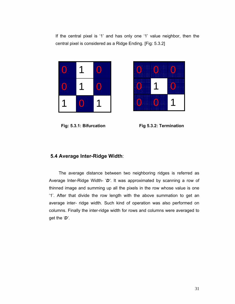
In general, for each 3x3 window, if the central pixel is ‘1’ and has exactly
three ‘1’ value neighbors, then the central pixel is considered as a Ridge
Branch. [Fig 5.3.1]
31
If the central pixel is ‘1’ and has only one ‘1’ value neighbor, then the
central pixel is considered as a Ridge Ending. [Fig: 5.3.2]
Fig: 5.3.1: Bifurcation Fig 5.3.2: Termination
5.4 Average Inter-Ridge Width:
The average distance between two neighboring ridges is referred as
Average Inter-Ridge Width- ‘D’. It was approximated by scanning a row of
thinned image and summing up all the pixels in the row whose value is one
‘1’. After that divide the row length with the above summation to get an
average inter- ridge width. Such kind of operation was also performed on
columns. Finally the inter-ridge width for rows and columns were averaged to
get the ‘D’.
10 1
01 0
01 0
1 00
0 1 0
0 00

32
60 FINGERPRINT IMAGE POST-PROCESSING 61 False Minutia Removal: The pre-processing stage does not absolutely cure the fingerprint
image. There will always be extraneous minutia found due to a noisy original
image or due to artifacts introduced by all the earlier stages which leads to
spurious minutia. Like, Thinning tends to introduce hair-like artifacts along the
one pixel wide skeleton, which leads to detection of spurious minutia. Sensing
system can also introduce false minutia. Such as in Live Scan, residues can
be left over on the glass platen from the previous fingerprint capture and on
the other hand in Off-Line fingerprint images, false ridge breaks due to
insufficient amount of ink and ridge cross-connects due too over inking. So
these false minutiae will significantly affect the accuracy of matching if they
are simply considered as genuine minutia. So some mechanisms of removing
false minutia are essential to keep the fingerprint recognition system effective.
These extraneous features are reduced by using empirically determined
thresholds. For instances a bifurcation having a branch that is much shorter
than an empirically determined short isolated line is eliminated because this
line is likely to be a spur. Two endings that are closely opposing are
eliminated because these are likely to be on the same ridge that has been
broken due to a scar or noise or a dry finger condition that results in
discontinuous ridges. Endings at the boundary of the fingerprint are eliminated
because they are not true endings but rather the extent of the fingerprint in
contact with the capture device.

33
Seven types of False Minutia re specified in following diagrams:
m1 m2 m3 m4
m5 m6 m7
Fig 6.1.1: False Minutia Structures. m1 is a spike piercing into a valley. In the m2
case a spike falsely connects two ridges. m3 has two near bifurcations located in the
same ridge. The two ridge broken points in the m4 case have nearly the same
orientation and a short distance. m5 is alike the m4 case with the exception that one
part of the broken ridge is so short that another termination is generated. m6 extends
the m4 case but with the extra property that a third ridge is found in the middle of the
two parts of the broken ridge. m7 has only one short ridge found in the threshold
window.
Procedures in Removing False Minutia applied in this Thesis are [3]:
1. If the distance between one bifurcation and one termination was less
than ‘D’ and the two minutiae were in the same ridge (case-m1). Then
both of them were removed. Where ‘D’ is the average inter-ridge width
representing the average distance between two parallel neighboring
ridges.
2. If the distance between two bifurcations was less than ‘D’ and they were
in the same ridge, the two bifurcations were removed. (cases- m2, m3).

34
3. If two terminations were within a distance ‘D’ and their directions were
coincident with a small angle variation and besides no any other
termination was located between the two terminations. Then the two
terminations were removed considered as false minutia which can be
derived from a broken ridge. (cases- m4, m5, m6).
4. If two terminations were located in a short ridge with length less than ‘D’,
they were removed. (case-m7).
Fig 6.1.2 and Fig 6.1.3 shows the fingerprint image after false minutia
removal.
This procedure in removing false minutia has two advantages. Firstly, the
ridge ID is used to distinguish minutia and the seven types of false minutia are
strictly defined. Secondly, the order of removal procedure is well considered
to reduce computational complexity. Like, the procedure-3 solves the m4, m5
and m6 cases in single check routine. And after procedure-3, the number of
false minutia satisfying the m7 case is significantly reduced.
But in low quality fingerprint images, the minutia extraction is process may
introduce a large number of spurious minutia and the system may not be able
to detect all the true minutiae. In this case a quality-checking algorithm can be
used to acquire and insert only good quality fingerprint images into the
database. A quality check is generally performed to ensure that acquired
sample can be reliably processed by successive stages. [1]
The result of the feature extraction stage is called ‘Minutia Template’, which
is a list of minutiae with accompanying attribute values.

35
Fig 6.1.2: Fingerprint Image Marking All Bifurcations and Terminations
(Left Side); after removing false Bifurcations and Terminations (Right Side)
Fig 6.1.3: Fingerprint Image Marking All Bifurcations (Left Side, Yellow
circle) after removing false Bifurcations (Right Side, Red circle)

36
After removal of the false minutiae, the path for each real minutia was
calculated, which is shown in [Fig 6.1.4]
Fig 6.1.4: Fingerprint Image after removing false Bifurcations (Left Side), Showing the Path of the Minutiae (Right Side)
6.2 Unify Terminations and Bifurcations:
Reliably matching fingerprint images is an extremely difficult problem,
mainly due to the large variability in different impressions of the same finger
(i.e., large Intra-Class variations). The main factors responsible for the Intra-
Class variations are: displacement, rotation, partial overlap, non-linear
distortion, variable pressure, changing skin condition, noise and feature
extraction errors. These can easily change one type of minutia in to the other
hand also fingerprint from the same finger may sometimes look quite different
whereas fingerprints from different fingers may appear quite similar. [1]

37
So the Unification representation for both termination and bifurcation is
adopted, that’s why each minutia is completely characterized by the following
parameters at last: i) x-coordinate, y-coordinate and iii) Orientation. [2]
The minutia orientation is defined as the direction of the underlying ridge at
the minutia location
.
(a) (b)
Fig 6.2.1: (a) A Ridge Ending Minutia: (x, y) are the minutia coordinates; θ is the minutia’s Orientation; (b) A Ridge Bifurcation Minutia: (x,y) are
the minutia coordinates; θ is the minutia’s Orientation [2]
As all three ridges deriving from the bifurcation point have their own direction,
the orientation calculation for a bifurcation need to be considered specially.
The method that has applied in this thesis is; at first break a bifurcation in to
three terminations. These three new terminations are the three neighbor
pixels of the bifurcation and each of the three ridges connected to the
bifurcation. Tracking a ridge segment which starting point is the termination
and length is ‘D’. Sum up all x-coordinates of points in the ridge segment.
Similar way the above summation was divided by ‘D’ to get ‘sx’ and ‘sy’. [3]
38
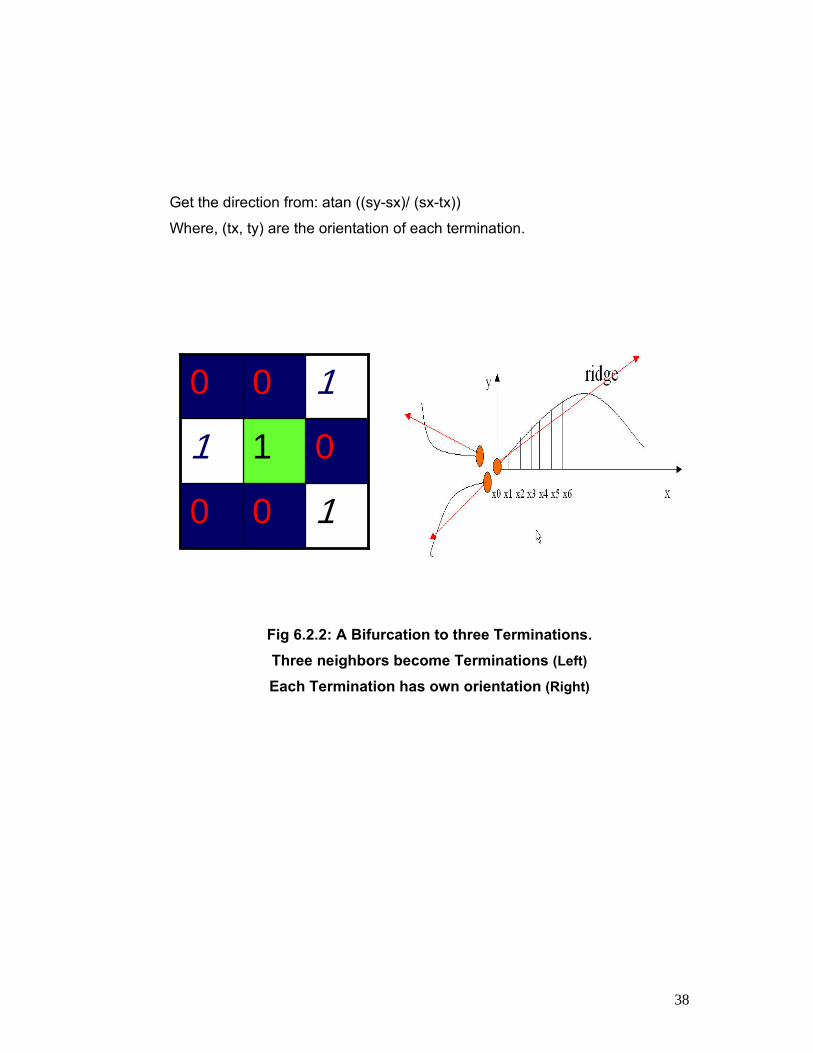
Get the direction from: atan ((sy-sx)/ (sx-tx))
Where, (tx, ty) are the orientation of each termination.
Fig 6.2.2: A Bifurcation to three Terminations. Three neighbors become Terminations (Left)
Each Termination has own orientation (Right)
1 0 0
01 1
10 0

39
7.0 MINUTIA MATCH
7.1 Match Period: Comparing between the set of minutia of two fingerprints, the Minutia
match algorithm determines whether the two minutia sets are from the same
finger or not. An alignment -based match algorithm includes two consecutive
stages: i) Alignment Stage and ii) Match Stage
7.1.1 Alignment Stage: Aligning the two fingerprints is a mandatory step in order to maximize
the number of matching minutiae. Correctly aligning two fingerprints certainly
requires ‘displacement’ (in x and y) and ‘rotation’ (θ) to be recovered and
likely involves other geometrical transformations such as ‘scale’ has to be
considered when the resolution of the two fingerprints may vary (e.g., the two
fingerprint images have been taken by scanners operating at different
resolutions) [1]
Choosing two minutia as a reference minutia pair and then setting the k-th,
minutia as origin and align its direction to zero (along x) and then
accommodate all other ridge points connecting to the minutia to the new
coordinate system If the similarity score of the ridges is larger than a threshold
then accommodating all other minutia points in the fingerprint to new origin
and two fingerprints are aligned for conducting matching for all minutiae.

40
The Alignment stage can be accomplished in to in-between two steps. For
each minutia the associated ridges are represented as a series of
x-coordinates (x1, x2, x3, …… xn ) of the points on that ridge. A point is
sampled per ridge length ‘L’ starting from the minutia point, where the ‘L’ is
the average inter-ridge length. And n is set to 10 unless the total ridge length
is less than ‘10*L’
The similarity of correlating the two ridges was derived from the following
formula:
S = ∑mi=0xiXi/ [∑m
i=0xi2Xi
2] ^0.5
Where (xi~xn) is a set of minutia for one fingerprint image and (Xi~Xn) is a
set of minutia for another fingerprint image who are going to be compared.
For both ‘n’ and ‘N’ value ‘m’ is one of the minimal.
All the minutiae of the fingerprint images were translated and rotated
according to the following formula with respect to the reference minutia:
⎥⎥⎥
⎦
⎤
⎢⎢⎢
⎣
⎡
i_new) ((yi_new)(xi_new)
θ= ⎟
⎟⎟
⎠
⎞
⎜⎜⎜
⎝
⎛ −
1 0 0 0 cos sin0 sincos
θθθθ
* ⎟⎟⎟
⎠
⎞
⎜⎜⎜
⎝
⎛
θθ -i Y-yiX-xi
In this formula, (x, y, θ) is the parameters of the reference minutia.
41
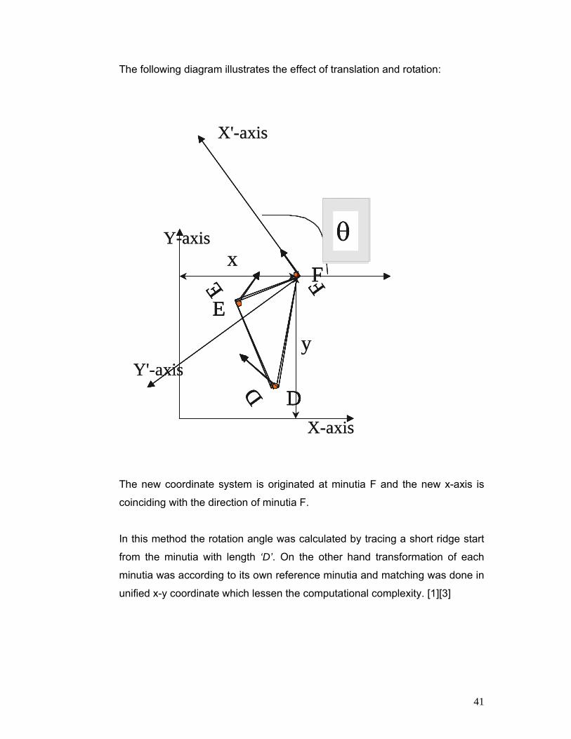
The following diagram illustrates the effect of translation and rotation:
The new coordinate system is originated at minutia F and the new x-axis is
coinciding with the direction of minutia F.
In this method the rotation angle was calculated by tracing a short ridge start
from the minutia with length ‘D’. On the other hand transformation of each
minutia was according to its own reference minutia and matching was done in
unified x-y coordinate which lessen the computational complexity. [1][3]
θD
E F
D
EF
X-axis
Y-axis
X'-axis
Y'-axisy
xθD
E F
D
EF
θD
E F
D
E F
D
EF
D
EF
X-axis
Y-axis
X'-axis
Y'-axisy
x

42
7.1. 2 Match Stage: After obtaining two set of transformed minutia points, matching
algorithm was applied to count the matched minutia pairs by assuming that
two minutiae were nearly same position and identical direction.
Matching fingerprint images is a complicated problem, mainly due to their
large inconsistency in unusual impressions of the same finger. Hence, the
matching algorithm should be expandable.
The matching algorithm was placing a rectangular bounding box of width and
height equal to 20 around each template minutia. If the minutia within the box
has small direction (pi/3) variation then they regarded as matched minutia
pair. Otherwise minutia within the template image has no matched or has only
one corresponding minutia.
The final matched ratio for two fingerprints were calculated dividing the total
number matched pair over the number of minutia of the template fingerprint.
The score is ‘100*ratio’ and ranges from 0 to 100. If the score is larger than a
pre-specified threshold value (60) than the two fingerprint images will be
considered are from the same finger.

43
8.0 Performance Measurement
Two indexes are well accepted to determine the performance of a
Fingerprint recognition system: one is False Rejection Rate (FRR) and the
other is False Accept Rate (FAR). [2][3][5]
• False Rejection Rate (FRR): The probability that the system incorrectly declares failure of match
between the input pattern and the matching template in the database is
known as False Rejection Rate (FRR) or False Non-match Rate (FNMR).
It measures the percent of valid inputs being rejected.
• False Accept Rate (FAR):
The probability that the system incorrectly declares a successful match
between the input pattern and a non-matching pattern in the database is
known as False Accept Rate (FAR) or False Match Rate (FMR). It measures
the percent of invalid matches.
The other indexes for performance Measurements are stated bellow [5]:
• Equal Error Rate (ERR):
The rates at which both accept and reject errors are equal. The lower
the ERR, the more accurate the system is considered to be.

44
• Failure to Enroll Rate (FTE or FER):
The percentage of data input is considered invalid and fails to input in
awto the system. Failure to enroll happens when the data obtained by the
aa sensor are considered invalid or poor quality.
• Failure to Capture Rate (FTC):
The probability that the system fails to detect a biometric characteristic,
aaaaa when it is presented correctly within the Automatic system.
• Template Capacity: The maximum numbers of sets of data which can be input in to the
aaaaa system.

45
8.1 Experimentation Results 8.1.1 Evaluation for Changed Images: After all the necessary steps described above, to check whether the
system is working properly or not, exactly two similar fingerprint images were
compared. The match result was 100% which proves that the system is
working in the approved manner.
As biometric recognition works on the principle of a threshold, so now the job
comes to settle on a Threshold value for this system.
A Threshold is a predetermined number which establishes the degree of
correlation necessary for a comparison between a biometric sample and
template to be deemed a match. [9]
There are some samples of the changed fingerprint images that were used in
this thesis represented in the figure 8.1.1:
(a) (b) (c) (d)
Fig 8.1.1: Changed Fingerprint Images
(a) rotated 3º clock wise; (b) added 50%noise; (c) rippled; (d) diffused

46
The Match results for 30 changed images:
Table-1: Match results of Changed Images
Image No
Type of Changes
Match results
1 Rotated 3º clock wise 61%
2 Rotated 5º clock wise 64.82%
3 Rotated 10º clock wise 61.67%
4 Rotated 11º clock wise 61.67%
5 Rotated 3º anti-clock wise 37.04%
6 Rotated 10º anti-clock wise 55.56%
7 Rotated 180º clock wise 96.67%
8 added noise 10% 73.33%
9 added noise 15% 55%
10 added noise 20% 95%
11 added noise 25% 65%
12 added noise 30% 68.33%
13 added noise 35% 66.67%
14 added noise 40% 61.67%
15 added noise 45% 66.67%
16 added noise 50% 83.33%
17 added noise 60% 81.667%
18 diffused glow 58.33%
19 added scratches 30%
20 added wave 51.67%
21 Diffused 45%
22 added dust 36.67%
23 Rippled 73.33%
24 Sharpen 70%
25 Custom 75%
26 Photocopy 83.33%

47
27 Rippled 25% 61.67%
28 sharpen more 68.33%
29 Rotated 90º clock wise 56.67%
30 Twirled 58.33%
It seen from the above analysis that among 30 changed images in 20
cases the match result was above 60% .As in 66.67% cases the match result
was found above 60% so the THRESHOLD value for this method has chosen
60%. That means if this system detects 60% similarity between two fingerprint
images then it can be decided that those two fingerprints are from the same
finger.
8.1.2 Evaluation for Different Images:
For more accurateness 25 totally different fingerprint images were
compared in this system.
There are some samples of the different fingerprint images that were used for
comparison are resented in the figure 8.2.1:
Fig 8.2.1: Different Fingerprint Images

48
The Match results for 25 different images:
Table-2: Match results of Different mages
Image no
Fingerprint Image name
Match results
1 finger_03.jpg 58.49%
2 finger_04.jpg 49.05%
3 finger_05.jpg 39.63%
4 finger_06.jpg 56.61%
5 finger_07.jpg 45.28%
6 finger_08.jpg 52%
7 finger_09.jpg 24.53%
8 finger_10.jpg 36%
9 finger_11.jpg 50%
10 finger_12.jpg 43%
11 finger_13.jpg 50%
12 finger_14.jpg 43%
13 Finger_15jpg 41.667%
14 finger_16.jpg 45%
15 finger_17.jpg 38.33%
16 finger_18.jpg 38.33%
17 finger_19.jpg 33.33%
18 finger_20.jpg 41.667%
19 finger_21.jpg 48.33%
20 finger_22.jpg 55%
21 finger_23.jpg 40.0%
22 finger_24.jpg 43..33%
23 finger_25.jpg 56.67%
24 finger_26.jpg 39.33%
25 finger_27.jpg 46.67%

49
All these 25 fingerprint images were rejected by the system as their entire
match results were bellow 60%, that means they did not satisfy the threshold
value. Hence, the sensitivity of this technology is close to 100% when applied
to different fingerprint images.
All 25 different fingerprint images and 30 changed fingerprint mages that were
used for analysis were first converted in to same size and same resolution.

50
9.0 Conclusion In this thesis several methods has applied for minutia extraction and
minutia matching algorithm which came from wide investigation in to research
papers. The results of all subsequent operations depend on the quality of the
images. The matching algorithm has large computational complexity and it is
vulnerable to spurious minutia but the intention is; the system offering a
reasonable speed with a correct answer is much better than a faster system
that yields inferior match result.
9.1 Future Work
• Improve the database to compare at least 50 fingerprint images at the
same time.
• Adding a Quality-Checking Algorithm to acquire and insert only good
quality fingerprint images in to the database.
• Developing a ‘Direct Gray-Scale Minutia Extraction’ to overcome some
problems caused by fingerprint Binarization and Thinning.
• Apply ‘Pre-Alignment Minutia Matching’ which is often able to operate
with noisy and incomplete data.

51
1. Handbook of Fingerprint Recognition by Davide Maltoni, Dario Maio,
aniAnil K. jain, Salil Prabhakar.
2. Minutia based partial fingerprint recognition by Tsai-Yang Jea.
3. “Fingerprint Recognition by WUZHILI “, published in www.comp.hkbu.edu.hk/~vincent/hp/fingerprintRecognition.doc
4. Digital Image Processing using MATLAB by Rafael C. Gonzalez,
ric Richard E. Woods, Steven L. Eddins
5. http://en.wikipedia.org/wiki/Biometrics
6. http://www.bromba.com/faq/fppage.htm#Minutien
7. http://homepages.inf.ed.ac.uk/rbf/HIPR2/threshld.htm
8. http://www.peoplekey.com.au/biometrics_tutor/glossary.htm
9. http://www.peoplekey.com.au/biometrics_tutor/fingerscanning.htm
10. http://pagesperso-orange.fr/fingerchip/biometrics/types/fingerprint.htm