final synopsis last
TRANSCRIPT
8/3/2019 Final Synopsis Last
http://slidepdf.com/reader/full/final-synopsis-last 1/17
1 | P a g e
VISION BASED, PC AND VOICE CONTROLLED WIRELESS FIRE DETECTING
AND
CONTROLLING ROBOT
A synopsis
Submitted by
RANJAN KAUL [Roll. No. 08-ECE-188]
ARINDAM BATABYAL [Roll. No. 08-ECE-120]
AAYUSHI NANDA [Roll. No. 08-ECE-101]
In partial fulfillment for the award of the degree
Of
BACHELOR OF TECHNOLOGY
DEPARTMENT OF ELECTRONICS & COMMUNICATION ENGINEERING
GURGAON INSTITUTE OF TECHNOLOGY&MANAGEMENT GURGAON, HARYANA ± 122413, INDIA
OCTOBER 2011
8/3/2019 Final Synopsis Last
http://slidepdf.com/reader/full/final-synopsis-last 2/17
2 | P a g e
TABLE OF CONTENTS
SERIAL NO. TOPIC PAGE NO.
1 INTRODUCTION
2 OBJECTIVE AND SCOPE
3 DESCRIPTION OF RESEARCH WORK
4 RESEARCH PROBLEM
5 RESEARCH METHODOLOGIES
6 RESULTS AND DISCUSSION
7 INTERPRETATION OF OUTPUTS
8 CONCLUSIONS
9 LIMITATIONS
10 REFERENCE

8/3/2019 Final Synopsis Last
http://slidepdf.com/reader/full/final-synopsis-last 3/17
INTRODUCTION
In areas like the fire chambers, coal mines etc the casualty rate can be drastically reduced where there
are maximum chances of tragedy and human intervention is also not possible. But the big question arises, as
to who would do the work? If only we had a machine which could do most of the dangerous work and which
could be operated from outside, things could be resolved. Presenting´VISION BASED PC
CONTROLLED WIRELESS FIRE DETECTING A ND CONTROLLING ROBOT´.
8/3/2019 Final Synopsis Last
http://slidepdf.com/reader/full/final-synopsis-last 4/17
4 | P a g e
OBJECTIVE
The entire project focuses that a utility vehicle in unfavorable conditions being controlled by computer placed a
few km from effected area and hence minimizing on the spot risk to human life. The camera mounted on the robo
provides us with the live video of the effected area. This helps us in visually analyzing the situation. The vide
received can be processed for detection and avoidances of object by the use of optical flow algorithms. The robo
can also be controlled via speech signal given by the operator at the station. S peech recognition converts spoke
words to machine-readable input (for example, to key presses, using the binary code for a string of characte
codes).The fire detecting and controlling unit is designed using Microcontrollers, Adc, Sensors etc which is aime
to detect temperature up to 150 degree Celsius. One may get amuse, why numbers of control logics are used. Th
simple answer to this is that, these types of robots are used in real time danger areas where the condition may b
worse than expected, hence one has to design a vehicle keeping in mind the risk management, if one control fail
then there must some other mechanism .in this project we have 4 ways to control the robot these are
1. Vision controlled (autonomous),
2. Control based on fire detection unit (autonomous),
3. Pc controlled via keyboard,
4. Voice controlled via microphone instructions.
Hence more the no. of control mechanisms, more reliable will the robot be. But the trade off between cost an
reliability must be met. This project is not only limited to an electronics student. While working on this projec
one gets an exposure in the following areas:-
1. Computer and Robot vision (Optical Flow Techniques, Digital Video Processing, Object Detection an
AvoidanceAlgorithms etc.)
2. Mechanical skills (Robot Design, Its Aerodynamics etc.)
3. Communication (Wireless communication between pc and robot.)
4. Computer programming skills (Programming the Parallel Ports, Designing the User Interface, Programming th
Microcontroller, Debugging techniques etc)
5. Electronics skills (Designing Fire Detecting Unit, Robot Navigation, Wireless Circuitry, Microcontroller
Analog And Digital Electronics, PCB Designing, Component Knowledge Etc)
6. Management skill (deciding between Cost and Reliability, Risk Management, Managing the Execution of Whol
Project in module form etc.)
8/3/2019 Final Synopsis Last
http://slidepdf.com/reader/full/final-synopsis-last 5/17
5 | P a g e
FUTURE SCOPE
1. NON DISPERSIVE INFRARED (NDIR) CO2 SENSORS
NDIR sensors are the simplest of the spectroscopic sensors. The key components are an infrared source, a lightube, an interference (wavelength) filter, and an infrared detector. The gas is pumped or diffuses into the light
tube and the electronics measures the absorption of the characteristic wavelength of light. NDIR sensors are
most often used for measuring carbon dioxide.T
he best of these have sensitivities of 20-50 PPM. Most areused for carbon dioxide, because no other sensing method works reliably for this gas. New developments
include using MEMS to bring down the costs of this sensor and to create smaller devices.
Its main features are:
High Sensitivity
Detection Range: 0 - 10,000 ppm CO2
Response Time: <60s
Heater Voltage: 6.0V
Dimensions: 16mm Diameter, 15mm High excluding pins, Pins - 6mm High
2. AIR QUALITY CONTROL SENSOR
Air quality sensor for detecting a wide range of gases, including NH3, NOx, alcohol, benzene, smoke andCO2.Ideal for use in office or factory, simply drive and monitoring circuit. Its main features are:
High Sensitivity
Stable and Long Life
Detection Range: 10 - 300 ppm NH3, 10 - 1000 ppm Benzene, 10 - 300 Alcohol
Heater Voltage: 5.0V
Dimensions: 18mm Diameter, 17mm High excluding pins, Pins - 6mm High
Its applications are:
Since the danger of fires comes mostly from its quickly spreading CO2 output, these sensors can be used to
detect fire and certain other air related problems safely without false alarm.
air quality monitoring
smoke alarms
mine and tunnel warning systems
detection of live human being in the deep mines

8/3/2019 Final Synopsis Last
http://slidepdf.com/reader/full/final-synopsis-last 6/17
6 | P a g e
3. HUMIDITY AND TEMPERATURE SENSOR
Humidity and temperature sensor with digital output. Provides 14 bit digital temperature and humidity output,
via a 2 wire SPI interface. No external components are required; the unit can be connected directly to a
microcontroller. Main features are:
Small Compact Size
Humidity Range: 0 - 100% RH Temperature Range: -40oC to 123oC
Resolution: 0.03 %RH and 0.01oC
Ideal for air-conditioning and home monitoring systems
Dimensions: 5.08mm Wide, 7.62mm High, 2.5mm Thickness
4. SURVEILLANCE AND PUBLIC TRANSPORT SYSTEM
We can also add digging and drilling mechanism to our ROBOT especially for the mining purposes.
We can add surveillance feature like trolley system by adding wireless ROBOT chasing the main ROBOT thru IR sensors.
The chasing ROBOT will sense the direction and movements of the main ROBOT without any human control
needed. This will help in mines where the following ROBOTs will chase the main ROBOT, decreasing the human
intervention in the dangerous areas in deep mines.
8/3/2019 Final Synopsis Last
http://slidepdf.com/reader/full/final-synopsis-last 7/17
7 | P a g e
RESEARCH PROBLEM
When designing your robot, think about what can go wrong, and then design your creation so these things cant go wrong
Below is a list of the 10 most common failures seen in robotics, all of which should be considered in your design process:
1.Wires coming loose, especially battery and radio control connections.
2. Improper charging or using insufficient-capacity batteries.
3. Speed controllers too small to handle the motor current requirements.
4. Motors, transmission, and batteries poorly mounted.
5. Belts and chains falling off.
6. Motors overheating.
7. Radio control interference.
8. Shearing and breaking fasteners.
9. Using homemade motor speed controllers.
10.Wheels becoming damaged by weapon or hazards, or jammed because of the body getting bent into them.
RESEARCH METHODOLOGIES
The first step in designing a new robot is deciding for which purpose the robot will be built if you¶re designing a
robot for multiple functions, you should decide various functions to be performed by it. Write down the physical
constraints .Once you have the physical constraints written down, you can start laying out the conceptual design of
your robot. Sketch out what you would like your robot to look like and do. Include the unique features and units
you would like your robot to have. A lot of this is paper-and-pencil or CAD (computer aided design) work. Next,
make a list of performance goals you¶d like to achieve, such as how fast you want your robot to go or how much
weight you want it to be able to push. What other functions a robot should do. The second list includes what you
are aiming for²the ultimate goal. Some people call this the brainstorming part of the design process. The ideas
come out here. As is the case with any brainstorming session, there is no such thing as a bad idea. Let the ideas
flow, and come up with some cool robot concepts. It is usually good to come up with a handful of them. After this
the conceptual ideas must be trimmed down to meet the physical constraints. In all robot design, the following
subsystems are part of each robot.
8/3/2019 Final Synopsis Last
http://slidepdf.com/reader/full/final-synopsis-last 8/17
8 | P a g e
Each of these subsystems relates to the others and affects the overall design of the robot:
y Robot frame
y Driver motors
y Power transmission
y Batteries
y Wheels
y Electronics
y Wireless control system
y Sensors
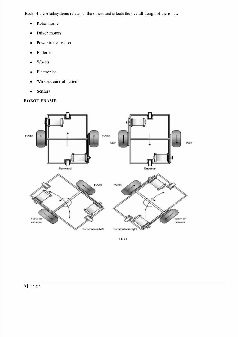
ROBOT FRAME:
FIG 1.1

8/3/2019 Final Synopsis Last
http://slidepdf.com/reader/full/final-synopsis-last 9/17
9 | P a g e
Wheels are generally categorized by steering method and mounting technique. One of the famous steering techniques is
differential technique, which is explained as follows:
Differential steering, sometimes called tank-type steering, is not to be confused with tank treads. The similarity is in the
way an operator can separately control the speeds of the left and right wheels to cause a directional change in the motion
of the robot. The above figure illustrates how controlling the speed and direction of both wheels with differential steering
can result in all types of directional motion for the robot.

8/3/2019 Final Synopsis Last
http://slidepdf.com/reader/full/final-synopsis-last 10/17
10 | P a g e
DRIVER MOTORS
Motors are the muscles of robots. Attach a motor to a set of wheels and your robot can scoot
around the floor. Attach a motor to a lever, and the shoulder joint for your robot can move up
and down. Attach a motor to a roller, and the head of your robot can turn back and forth,
scanning its environment.
FIG 1.2
With stepping motors, shown in Fig, the application of power causes the shaft to rotate a few degrees, and then
stop. Continuous rotation of the shaft requires that the power be pulsed to the motor. As with continuous DC
motors, there are subtypes of stepping motors. Permanent magnet steppers are the ones you¶re likely to encounter,and they are also the easiest to use.
VOLTAGE REGULATORS
Voltage regulators produce fixed DC output voltage from variable DC (a small amount of AC on it). Normally we get fixed output by connecting the voltage regulator at the output of the filtered DC (see in
above diagram). It can also used in circuits to get a low DC voltage from a high DC voltage (for examplewe use 7805 to get 5V from 12V).
8/3/2019 Final Synopsis Last
http://slidepdf.com/reader/full/final-synopsis-last 11/17
11 | P a g e
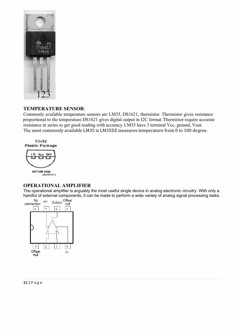
TEMPERATURE SENSOR :
Commonly available temperature sensors areL
M35, DS
1621, thermistor.T
hermistor gives resistance proportional to the temperature.DS1621 gives digital output in I2C format.Thermistor require accurate
resistance in series to get good reading with accuracy.LM35 have 3 terminal Vcc, ground, Vout.
The most commonly available LM35 is LM35DZ measures temperature from 0 to 100 degree.
OPERATIONAL AMPLIFIER The operational amplifier is arguably the most useful single device in analog electronic circuitry. With only ahandful of external components, it can be made to perform a wide variety of analog signal processing tasks.
8/3/2019 Final Synopsis Last
http://slidepdf.com/reader/full/final-synopsis-last 12/17
12 | P a g e
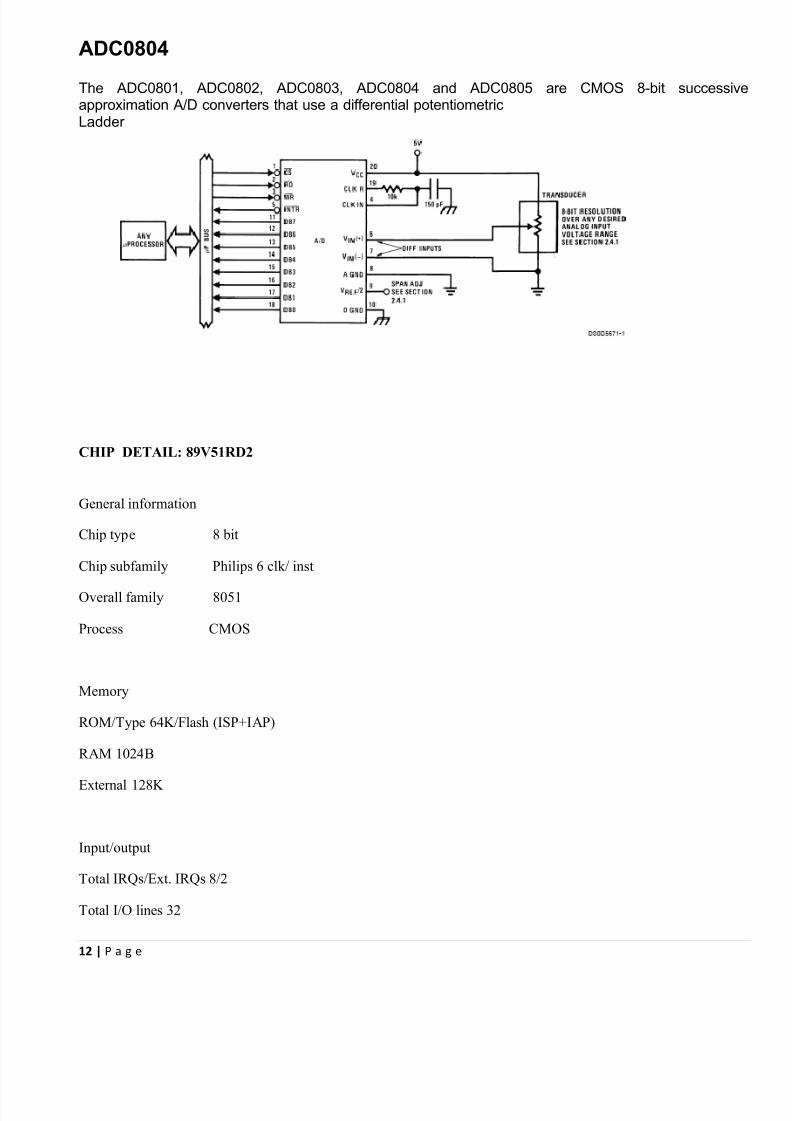
ADC0804
The ADC0801, ADC0802, ADC0803, ADC0804 and ADC0805 are CMOS 8-bit successivapproximation A/D converters that use a differential potentiometricLadder
CHIP DETAIL: 89V51RD2
General information
Chip type 8 bit
Chip subfamily Philips 6 clk/ inst
Overall family 8051
Process CMOS
Memory
ROM/Type 64K/Flash (ISP+IAP)
R AM 1024B
External 128K
Input/output
Total IRQs/Ext. IRQs 8/2
Total I/O lines 32

8/3/2019 Final Synopsis Last
http://slidepdf.com/reader/full/final-synopsis-last 13/17
13 | P a g e
Ext I/O lines 14
Timers, counters 3
UAR Ts 1
ADC Inputs/resolution 0/0
Watchdog True
PWM outputs 5
Designed For Low Power True
Physical/electrical
Op. Voltage 4.5 - 5.5V
Clock type Crystal, External
Manufacturers Philips

8/3/2019 Final Synopsis Last
http://slidepdf.com/reader/full/final-synopsis-last 14/17
14 | P a g e
8/3/2019 Final Synopsis Last
http://slidepdf.com/reader/full/final-synopsis-last 15/17
15 | P a g e
CONCLUSION:
Many more such applications can be done with taking this project as a ground to work on. This project was
aimed to explain the concepts involved in making a robot with added qualities such as vision, voice control,
fire detection and controlling etc. Many more other different modules ca be mounted on the robot depending
upon the need .
LIMITATIONS
1. The robot has limited range due to following reasons :
y The robot runs on a battery pack and thus has limited duration of working until the battery dies out.
y The robot has limited range due operational range of the wireless signals.
2. The robot needs human intervention as if the robot falls it needs to be manually set straight.
8/3/2019 Final Synopsis Last
http://slidepdf.com/reader/full/final-synopsis-last 16/17
16 | P a g e
LIST OF REFERNCES
1. http://www.logix4u.net/
2. http://www.mcmanis.com/chuck/Robotics/tutorial/h-bridge/bjt-circuit.html
3. Help Menu: Microsoft Visual Basics 2008 Express Edition
4. http://logix4u.net/Legacy_Ports/Parallel_Port/A _tutorial_on_Parallel_port_Interfacing.html
5. http://www.datasheetcatalog.com/datasheets_pdf/L/2/9/8/L298N.shtml
6. http://www.datasheetsite.com/datasheet/HT-12D
7. http://datasheetcatalog.biz/datasheets/electronical-components/datasheet-download/HT-12E-S/153122.html
8.http://www.csharpcorner.com/UploadFile/ggaganesh/UsingMSAgentinCSharpPartIIS peechRecognition1123200
5011052AM/UsingMSAgentinCSharpPartIIS peechRecognition.aspx
9. http://msdn.microsoft.com/en-us/library/aa984739 (VS.71).aspx
10. http://www.w3schools.com/xml/default.asp
11. http://xmlfiles.com/
12. The 8051 microcontroller and embedded system - By MA Mazidi, JC Mazidi and RD McKinley.
13. Keil development tools for the 8051 Microcontroller Architecture support every level of software developer
from the professional applications engineer to the student just learning about embedded software development
14. 7805 (Voltage regulators) http://www.datasheetcatalog.net/datasheets_pdf/7/8/0/5/7805.shtml
15. Lm 35 (Temperature sensor) www.national.com/ds/LM/LM35.pdf
16. Lm 358(Operational amplifier) www.national.com/ds/LM/LM158.pdf
17. Timer 555 www.national.com/pf/LM/LM555.html
18. ICL 7135 (ADC) www.intersil.com/data/fn/fn3093.pdf
19. AT 89v51 (Microcontroller) www.atmel.com/dyn/resources/prod_documents/doc1919.pdf
20. LCD http://www.sparkfun.com/datasheets/LCD/HD44780.pdf

8/3/2019 Final Synopsis Last
http://slidepdf.com/reader/full/final-synopsis-last 17/17
17 | P a g e
CONCLUSION
In this chapter various devices used in the project are discussed with their circuit diagram and
Integration of all the devices to design fire detecting and controlling unit is also explained.
After this stage we are now in a state of integrating all the above chapters to have a complete
Overview of designed robot and its functions. In the next chapter various block diagrams of
Whole project are given and some future prospects of this are also given.