final supplemental environmental impact statement for … · the town of mount pleasant,...
TRANSCRIPT

FINAL SUPPLEMENTAL ENVIRONMENTAL IMPACT STATEMENT FOR THE CROTON WATER TREATMENT PLANT
AT THE MOSHOLU SITE 6. WATER TREATMENT PLANT AT THE MOSHOLU SITE.............................................. 1
6.1. INTRODUCTION AND PROJECT DESCRIPTION.................................................... 1 6.1.1. Site Description....................................................................................................... 1
6.1.1.1. Topography..................................................................................................... 2 6.1.1.2. Surface Water.................................................................................................. 2 6.1.1.3. General Geology ............................................................................................. 3 6.1.1.4. Seismicity........................................................................................................ 3 6.1.1.5. Subsurface Conditions .................................................................................... 3
6.1.2. Water Treatment Plant at the Mosholu Site............................................................ 4 6.1.2.1. Raw Water Supply .......................................................................................... 5 6.1.2.2. Raw Water Conveyance.................................................................................. 7 6.1.2.3. Water Treatment Plant .................................................................................... 8 6.1.2.4. Treated Water Conveyance........................................................................... 20 6.1.2.5. Treated Water Pumping Station.................................................................... 21 6.1.2.6. Treated Water Tunnels and Distribution System Operation......................... 22 6.1.2.7. Treated Water System Off-Site Facilities ..................................................... 22 6.1.2.8. Solids Handling............................................................................................. 27
FIGURE 6.1-1. CROTON WATERSHED AND RESERVOIRS................................................. 6 FIGURE 6.1-2. AERIAL VIEW OF THE PROPOSED PROJECT AT THE MOSHOLU SITE
............................................................................................................................................... 14FIGURE 6.1-3. LOCATION OF THE PROPOSED CROTON PROJECT AT THE MOSHOLU
SITE ...................................................................................................................................... 15 TABLE 6.1-1. TREATED WATER QUALITY GOALS.............................................................. 9 TABLE 6.1-2. CHEMICAL SYSTEM DESIGN CRITERIA1 ................................................... 11 TABLE 6.1-3. PROPOSED PLANT STATISTICS.................................................................... 13 TABLE 6.1-4. PROCESS LABORATORY ANALYTICAL REQUIREMENTS AND WASTE
DISPOSAL ........................................................................................................................... 16 TABLE 6.1-5. ESTIMATED ELECTRICAL POWER DEMANDS FOR THE PROPOSED
PLANT.................................................................................................................................. 17

6. WATER TREATMENT PLANT AT THE MOSHOLU SITE 6.1. INTRODUCTION AND PROJECT DESCRIPTION The New York City Department of Environmental Protection (NYCDEP) proposes to design, construct and place into operation a 290 million-gallon-per-day (mgd) Croton Water Treatment Plant (Croton project) to provide filtration and disinfection of the Croton Water System. The project would also include the construction of new raw water and treated water tunnels to connect the proposed plant to the New Croton Aqueduct (NCA), and improvements and rehabilitation of structures related to distribution connections at and near Jerome Park Reservoir. Three sites for the water treatment plant are evaluated in this Draft SEIS: The Eastview Site in the Town of Mount Pleasant, Westchester County; the Mosholu Site in the Bronx, Bronx County; and the Harlem River Site, also in the Bronx, Bronx County. Some alternatives include work at other sites along the New Croton Aqueduct (NCA), and one alternative includes a future connection to the proposed Kensico-City Tunnel. This project description provides details relating to construction and operation of the proposed plant at the Mosholu Site. Construction of the proposed Croton project at the Mosholu Site would include a new raw water tunnel to convey untreated water from the NCA to the water treatment plant site; a raw water pumping station; a main treatment building located underground that would house all the process elements, administrative offices, a conference room, a small process laboratory, maintenance and storage facilities, electrical and heating, ventilation and air conditioning (HVAC) rooms; a treated water pumping station; and a new treated water tunnel to convey treated water from the proposed plant back to Jerome Park Reservoir (JPR) and the City’s distribution system. The Mosholu Site is the most secure site since the treatment facilities are located below ground. During construction, an approximately 800-foot long ornamental wall would be constructed along Jerome Avenue that would provide a visual barrier and aid in noise attenuation. In addition, construction of the proposed plant would require the rehabilitation and stabilization of several off-site Croton System facilities. The off-site location points where activity would occur include the following: Gate House No. 1 (Bronx, NY) and modifications to the facilities in and around the Jerome Park Reservoir (Bronx, NY). Work required at these off-site locations is described in Section 8, Off-Site Facilities. 6.1.1. Site Description The Mosholu water treatment plant would be located at the Mosholu Golf Course and Driving Range. The site is located within the 1,146-acre Van Cortlandt Park in the Borough of the Bronx, New York. This site is owned by the City and is under the jurisdiction of the NYC Department of Parks and Recreation (NYCDPR). The golf course and driving range is bound by the Mosholu Parkway and Major Deegan Expressway to the west and north, Jerome Avenue and the Interborough Rapid Transit (IRT) No. 4 elevated subway (the Woodlawn station) to the east, and West Gun Hill Road to the south. The golf course and driving range comprise approximately 74 acres of the 1,146-acre park. Existing facilities at the water treatment plant site include a clubhouse, driving range, nine-hole course and a parking lot for approximately 75 cars. The proposed project would be situated under a portion of the 13-acre driving range. During construction the golf course would remain open with a temporary clubhouse, driving range, and parking facilities made available through the Allen Shandler Recreation Area to the north, adjacent to the golf course and driving range. The temporary golf course would be a
Final SEIS MOSPRO 1

modification of the existing one, and would still have 9 holes open to the public during the construction period. Following construction, these facilities would be replaced with a new golf course clubhouse, maintenance facility, and new golf course parking lot. The nine-hole golf course would be replaced with an 18-hole “Executive” (short-hole) course with a possible alternative of a nine-hole golf course in the future. 6.1.1.1. Topography
The water treatment plant site (currently the driving range) slopes gently from west to east, from about Elevation 205 to Elevation 170 feet MSL. The area rests on firm soil substratum, which is, in general, moderately deep over bedrock. The topography of the general area is largely bedrock, as evidenced by large boulders, which are visible on the slopes along Jerome Avenue to the east and West Gun Hill Road to the south. It is likely that the original site topography has been previously modified through excavation and backfill for landscaping of the golf course and driving range. 6.1.1.2. Surface Water
There are no surface water bodies on the water treatment plant site. Five wetland areas, one drainage swale, one drainage ditch, and two stormwater overflow ditches are located within the study area of the proposed water treatment plant site. Table 6.14-1 lists the resources in the study area and their dimensions. None of these areas is within the proposed construction impact area. These areas are depicted in Figure 6.14-1. A red maple hardwood swamp (WL-A) located in the northern half of the study area totals approximately 1.60 acres. The second wetland area is an impounded marsh with an adjacent drainage swale. The second wetland (WL-B) is approximately 0.02 acres in size and the drainage swale (DS-A) is approximately 0.03 acres in size. Down slope of the WL-B wetland, the channel disappears and water appears to flow underground prior to reaching the drainage swale depicted at DS-A. The third wetland area (WL-C) is a palustrine-forested wetland (red maple hardwood swamp) in the northern half of the study area that is approximately 0.1 acres. The WL-C wetland is hydrologically connected to the artificial ditch traversing east to west near the northern border of the ball field (Figure 6.14-1). The ditch is labeled as DD-A and is approximately 0.02 acres in size. This ditch appears to have been constructed in an attempt to collect sheet runoff from upslope areas and divert it around the northern baseball field. However, a substantial amount of runoff was observed collecting downslope of the ditch and on the baseball field during the on-site investigations. The forested wetland depicted as WL-D occupies approximately five acres and is located to the north of the access road to the water treatment plant site (Figure 6.14-1). This wetland is immediately north of the site access road. Based on the data from 101 borings, the groundwater elevation is coincident with the surface water elevation of this wetland. (164.5 ft. MSL). The rock topography provides additional evidence that the hydrology of this wetland is controlled by groundwater. The other wetlands in the study area are higher and are perched above the water table. This wetland receives drainage from a catch basin in the golf course parking lot via a pipe labeled SO-B in Figure 6.14-1. Finally, one isolated wetland approximately 0.30 acres in size is located adjacent to the area of potential construction impact (Figure 6.14-1). This vernal pool wetland is identified on the figure as WL-E.
Final SEIS MOSPRO 2

The five wetlands are regulated by the ACOE under the Clean Water Act, but are not regulated by the State of New York principally because they are less than 12.4 acres in size and are not depicted on the New York State Department of Environmental Conservation (NYSDEC) Freshwater Wetlands map for the Bronx. No construction activity would take place near any of the five wetlands described above. Additional information, including the modeling results and potential environmental impacts, are presented in Section 6.14, Natural Resources, and Section 6.15, Water Resources. 6.1.1.3. General Geology
This area of the Bronx is largely a product of pre-glacial stream erosion, modified somewhat by glacial erosion and deposition. This water treatment plant site is overlain by Pleistocene glacial till and bedrock belonging to the Precambrian Fordham Gneiss Formation. The Fordham gneiss is a massive, coarsely crystalline gray and white-banded rock of complex composition and structure that generally underlies the areas of high relief in the western portion of the Bronx where the water treatment plant site is located. 6.1.1.4. Seismicity
This area is located in the general seismic zone 2A under the 1988 Uniform Building Code (UBC). The New York City Building Code requires a Seismic Factor Z of 0.15 and a Site Coefficient of 0.67 for foundations bearing on bedrock and 1.0 for foundations bearing on glacial soil, medium dense to very dense glacial till. This zone is within an area characterized by a low risk of seismic activity but not completely without some probability of minor ground movement. Consequently, building codes require the foundation and framing members to meet certain strength, elasticity, and anchoring requirements as listed above. 6.1.1.5. Subsurface Conditions
The generalized subsurface profile of the water treatment plant site, starting from the surface, is described below.
6.1.1.5.1. Surficial Soils
Surficial soils include areas of soil materials used for landscaping, roadbed or deposited from post-construction activities and site maintenance. These soils range from 0 to 34 feet in depth. They are often sand, silty sands, gravel and topsoil of varying consistency and appear to be very shallow. They also may include organic matter and a few boulders in the upper two feet.
6.1.1.5.2. Bedrock
The overburden soils described above are underlain by bedrock from the Fordham Gneiss Formation, consisting of a foliated light-to-medium gray muscovite-biotite-plagioclase-quartz-gneiss, locally transitioning to an amphibilitic or quartz-banded gneiss. The Fordham Gneiss is generally a hard rock with poorly defined joint sets; at the water treatment plant site, major jointing is in the northwesterly direction. At the water treatment plant site, the top of the rock is locally weathered to a clay-like material (saprolite). The depth to bedrock varies from four to 40
Final SEIS MOSPRO 3

feet, averaging 15 feet. Typically, bedrock quality improves with depth, achieving Class 2-65 to 1-65.
6.1.1.5.3. Groundwater
The groundwater is found roughly at the bedrock surface and ranges from approximately Elevation 185 feet to Elevation 170 feet. Groundwater levels are at Elevation 185 feet for about 75 percent of the water treatment plant site and at Elevation 170 feet for about 25 percent of the water treatment plant site. 6.1.2. Water Treatment Plant at the Mosholu Site The proposed project at the Mosholu Site would include the proposed water treatment plant with a raw water and treated water pumping station and raw and treated water connections to the City’s distribution system via the NCA and City Tunnel Nos. 1 and 3. The treatment processes would be housed within the main treatment building along with the administrative offices, chemical storage, a process laboratory, security and maintenance, and the HVAC system. The proposed plant layout would be designed to minimize space requirements. This design practice involves using appropriate loading rates in the treatment processes, common wall construction with rectangular treatment units, and vertical stacking of some process components. Below-grade structures and water-retaining structures would be constructed of reinforced concrete. The structural components would be designed in accordance with state and local codes to accommodate normal and seismic forces. The proposed plant design would incorporate levels of redundancy based on good engineering practices and regulatory requirements. NYCDEP’s standard approach to critical equipment redundancy is to provide “n+1+1” equipment units, where “n” is the number of units required for maximum design conditions. These design levels of redundancy, at a minimum, satisfy the requirements of Recommended Standards for Water Works, also referred to as the Ten State Standards, which is based on n+1. Although these n+1+1 design levels of redundancy are not considered mandatory, they would be used in the process design and by the NYSDOH as a guideline for approval of the proposed project. Therefore, the proposed project would incorporate an “n+1+1”1 redundancy for the critical equipment design. The proposed plant would be designed such that the main flow of water through the treatment processes would be by gravity, with pumping used to lift raw water to the entrance of the treatment process at the proposed plant. Treated water would flow by gravity to the Low Level service areas and would be pumped when conveyed to the High Level service areas (see Section 3, Proposed Project and Engineering Alternatives). The average design flow would be 144 mgd with a maximum design flow of 290 mgd. With the design principle that no single plant component would treat, convey, or power more than 50 percent of the plant design flow, in the event of an unforeseen shutdown or emergency, the main treatment processes would be divided into two separate water treatment trains, Train A and Train B2. 1 n+1+1 means that a process or piece of equipment has two full standby or backup units so that it can be taken out of service for maintenance and a backup can take over the process. If the backup is affected in some way that takes it out of service, there is additional equipment to take over the process. 2 In this project, a process train refers to a sequentially ordered set of things or events in which each successive member is related to the preceding and mandatory to produces a common goal.
Final SEIS MOSPRO 4

6.1.2.1. Raw Water3 Supply
The original Croton System was constructed in the mid 1800s, but only a portion of that system is still in use today. The present Croton System, constructed between 1885 and 1911, normally provides approximately 10 percent of the City’s daily water supply and can provide up to 30 percent during drought conditions. The Croton System consists of twelve reservoirs and three controlled lakes on the Croton River, its three branches and three other tributaries (Figure 6.1-1). The water flows from upstream reservoirs through natural streams to downstream reservoirs, terminating at the New Croton Reservoir. With a watershed area of approximately 375 square miles, the system lies almost entirely within the State of New York, with a small portion in the State of Connecticut. Situated approximately 45 miles north of the center of Manhattan, the watershed has been subjected to suburban-type development over the years, which has affected the quality of the water source. A limited amount of water can be transferred from the Croton System to the higher level Delaware System at West Branch Reservoir, and water can also be transferred by gravity from the Catskill System into the NCA through the Croton Lake Gate House4 in the Town of Yorktown. During outages of the Croton System the Catskill/Delaware System can meet all of the City’s water needs. Water is conveyed from the New Croton Reservoir through the NCA to the Jerome Park Reservoir. The NCA is approximately 31 miles in length with a delivery capacity of approximately 290 mgd. The NCA is located up to 400 feet below ground and is composed of two sections. The northern section is primarily a brick-lined at grade tunnel constructed in rock and originating near the now submerged Old Croton Dam, about three miles upstream of the Cornell Dam on the New Croton Reservoir, and extending to Gate House No. 1 in Van Cortlandt Park, a distance of about 24 miles. This section is horseshoe-shaped, 13.5 feet high by 13.6 feet wide, and is not pressurized. The invert was constructed at a constant slope of about 0.7 feet per mile. The northern section also includes a short section of a 14.25-foot diameter pressure tunnel near Tarrytown. The southern section is a pressurized brick-lined tunnel extending from Gate House No. 1 to Shaft No. 33 at 135th Street and Convent Avenue in Manhattan, a distance of about seven miles. For the most part, this section is 12.25 feet in diameter. In addition, a branch of the NCA, the New Croton Branch Aqueduct (NCBA) transmits water from Gate House No. 1 to Jerome Park Reservoir, a distance of about one mile.
3 Means unfiltered water. 4 The Croton Lake Gate House controls the amount of water that enters the northern most entry point to the NCA. Final SEIS MOSPRO 5

5 0Scale
10 Km
Boyd’s Reservoir
Dutchess
Putnam
Westchester
West BranchReservoir
Lake Gleneida
Bog BrookReservoir
CROTON FALLS
CROSS RIVER
WEST BRANCH
NEW CROTON
Middle BranchReservoir
Lake Kirk
Lake Gilead
Amawalk Reservoir
New Croton Reservoir
Cross RiverReservoir
TiticusReservoir
DivertingReservoir
East BranchReservoir
Croton FallsReservoir
Aqueduct
Sub-System Boundary
Drainage Basin Boundary
County Boundary
Reservoirs
Cats
kill A
qu
ed
uct
MuscootReservoir
New Croton Aqueduct
Croton Watershed and Reservoirs
Delaw
are Aqueduct
Ne
w Y
ork
Co
nn
ect
icu
t
M&
E F
ile: P
:\E
nvi
ron
me
nta
l Qu
alit
y\C
roto
n\2
00
4 F
ina
l SE
IS\G
RA
PH
ICS
\06
-MO
S\0
1-P
RO
DE
SC
\MO
S-p
rod
esc
A-0
5-1
0-0
4.c
dr
05
/13
/04
New Croton / Cornell Dam
Croton Lake Gate House
Figure 6.1-1
Croton Water Treatment Plant

6.1.2.2. Raw Water Conveyance
Similar to current practices, raw water would be conveyed from the Croton Lake Gate House through the NCA to Gate House No. 1. From there, under average flow conditions (144 mgd), water would travel through the NCBA to Jerome Park Reservoir, where raw water would discharge through the south portal into the south basin of the reservoir. Water circulates to the north basin through six 60-inch pipelines through the dividing wall. Passing through Gate House No. 3 in the south basin, the raw water would be directed through existing pipes to Gate House No. 5. From Gate House No. 2 in the North Basin, raw water would pass through existing pipelines and be directed to Gate House No. 5. Once reaching Gate House No. 5, raw water would be conveyed through an 11-foot conduit back to the NCA via Shaft No. 21 (situated north of the dividing wall). A new plug would be installed just south of the shaft preventing raw water from entering into the City’s distribution system, directing the flow northwards towards a new water tunnel and the proposed plant. Once the raw water is in the Jerome Park Reservoir, the channeling of water through the various valves and gate houses is standard under current conditions. This channeling allows impurities within the water to settle and allows operators to control the flow of water in, through, and out of the reservoir. Under maximum flow conditions (290 mgd), additional flow would be directed at Gate House No. 1 to continue southward in the NCA to the new raw water tunnel (described below) and to the new raw water shaft at the proposed plant. In addition, under emergency conditions or if both basins of Jerome Park Reservoir are taken off-line, all flows would travel through the NCA directly to the raw water tunnel and then to the proposed plant.
6.1.2.2.1. Raw Water Tunnel
A new 900-foot-long raw water tunnel would extend from a new NCA connection, Elevation 7, downstream of NCA Shaft No. 20, eastward towards the new raw water shaft adjacent to the proposed plant. Along this route the tunnel would slope down towards the inlet channel of the new raw water shaft. The invert elevation of the raw water shaft would be at Elevation 5, approximately 195 feet below grade. From the new shaft, the tunnel would continue eastward to a new raw water pumping station on the west side of the proposed plant.
6.1.2.2.2. Raw Water Pumping Station
The purpose of the raw water pumping station would be to convey the raw water from the new tunnel into the proposed plant. The water would be under pressure based on the surface elevation of Jerome Park Reservoir as it enters the pumping station. To do so, pumps would lift the raw water approximately 35 feet into the plant inlet (i.e. entrance). The raw water pumping station would be sized for maximum operating conditions (290 mgd) with six raw water pumps installed, each with a capacity of 74 mgd. Therefore, with three pumps designated for each half of the proposed plant, Train A and Train B, two in operation and one in standby, a total of 148 mgd of raw water would be pumped to the head of the proposed plant by each train.
Final SEIS MOSPRO 7
6.1.2.3. Water Treatment Plant
6.1.2.3.1. Treatment Process Goals
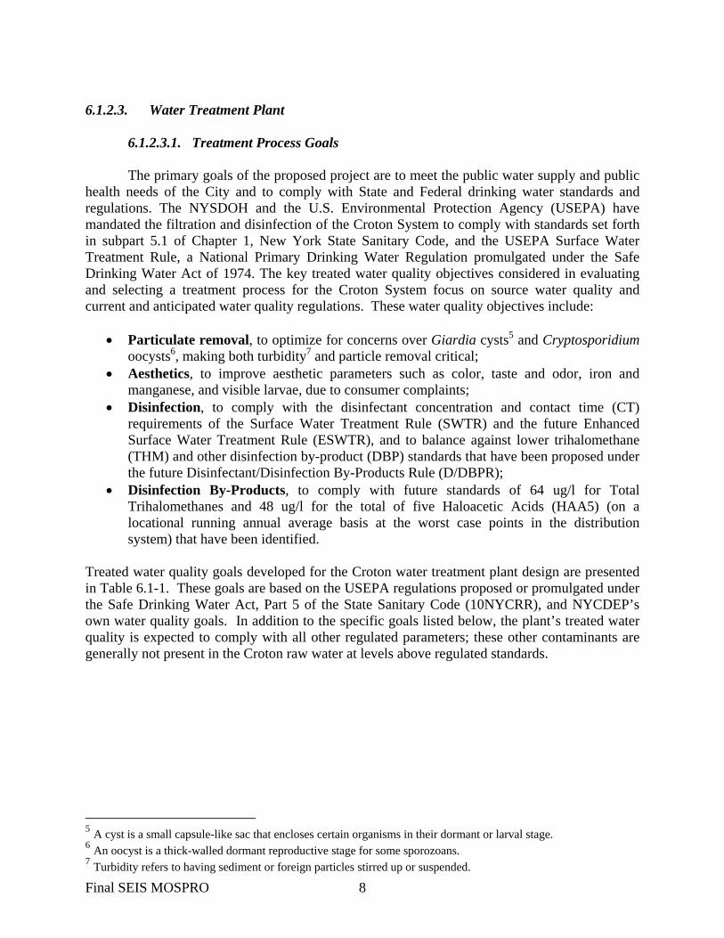
The primary goals of the proposed project are to meet the public water supply and public health needs of the City and to comply with State and Federal drinking water standards and regulations. The NYSDOH and the U.S. Environmental Protection Agency (USEPA) have mandated the filtration and disinfection of the Croton System to comply with standards set forth in subpart 5.1 of Chapter 1, New York State Sanitary Code, and the USEPA Surface Water Treatment Rule, a National Primary Drinking Water Regulation promulgated under the Safe Drinking Water Act of 1974. The key treated water quality objectives considered in evaluating and selecting a treatment process for the Croton System focus on source water quality and current and anticipated water quality regulations. These water quality objectives include:
• Particulate removal, to optimize for concerns over Giardia cysts5 and Cryptosporidium oocysts6, making both turbidity7 and particle removal critical;
• Aesthetics, to improve aesthetic parameters such as color, taste and odor, iron and manganese, and visible larvae, due to consumer complaints;
• Disinfection, to comply with the disinfectant concentration and contact time (CT) requirements of the Surface Water Treatment Rule (SWTR) and the future Enhanced Surface Water Treatment Rule (ESWTR), and to balance against lower trihalomethane (THM) and other disinfection by-product (DBP) standards that have been proposed under the future Disinfectant/Disinfection By-Products Rule (D/DBPR);
• Disinfection By-Products, to comply with future standards of 64 ug/l for Total Trihalomethanes and 48 ug/l for the total of five Haloacetic Acids (HAA5) (on a locational running annual average basis at the worst case points in the distribution system) that have been identified.
Treated water quality goals developed for the Croton water treatment plant design are presented in Table 6.1-1. These goals are based on the USEPA regulations proposed or promulgated under the Safe Drinking Water Act, Part 5 of the State Sanitary Code (10NYCRR), and NYCDEP’s own water quality goals. In addition to the specific goals listed below, the plant’s treated water quality is expected to comply with all other regulated parameters; these other contaminants are generally not present in the Croton raw water at levels above regulated standards.
5 A cyst is a small capsule-like sac that encloses certain organisms in their dormant or larval stage. 6 An oocyst is a thick-walled dormant reproductive stage for some sporozoans. 7 Turbidity refers to having sediment or foreign particles stirred up or suspended. Final SEIS MOSPRO 8

TABLE 6.1-1. TREATED WATER QUALITY GOALS
Constituent Goal Microbiological Giardia cysts ≥99.9% removal and inactivation Cryptosporidium oocysts ≥99.9% removal and inactivation Viruses ≥99.99% removal and inactivation Filtered water turbidity ≤0.10 ntu for 95% of time Particles (>2 µm) Steady state operation Regrowth potential BDOC(1) not more than raw water levels
(seasonally adjusted) Disinfection By-Products Trihalomethanes (total) 64 µg/l (4-quarter RAA(2)) Haloacetic acids (HAA5) 48 µg/l (4-quarter RAA) Bromate ≤5 µg/l Inorganics Aluminum ≤0.05 mg/l Corrosion control Maintain finished water pH of 7.0-7.5 Iron ≤0.10 mg/l Manganese ≤0.05 mg/l Other Total organic carbon >35% removal, or <2 mg/l in filtered water True color ≤5 scu Tastes and odors Treat to minimize (1) Biodegradable Dissolved Organic Carbon (BDOC) (2) Running Annual Average (RAA)
6.1.2.3.2. Treatment Processes
To satisfy the above-mentioned criteria, the selected treatment process for the proposed
plant would be a “stacked” dissolved air flotation/filtration (DAF/Filtration) followed by disinfection (Ultraviolet light (UV) and chlorination). Pre-treatment in support of this process includes mixing/coagulation, flocculation, and chemical adjustment. Post-treatment includes further chemical adjustment and fluoridation. This selection would achieve or exceed treated water quality goals including a 99.9 percent (3-log) removal/inactivation of Giardia cysts and 99.9-percent (3-log) removal of Cryptosporidium oocysts. DAF is used to remove particulate matter from the water stream. It is followed by filtration, which further removes particulates to achieve required turbidity levels. Use of DAF in conjunction with filtration would optimize the particulate removal component of the process. Disinfecting filtered water with ultraviolet light technology would provide further treatment for inactivation of pathogens. At an achievable dose, UV disinfection has been found to effectively prevent the Cryptosporidium oocyst from replicating and is therefore shed from a host’s digestive tract without causing illness. UV has also been found to render Giardia lamblia cysts non-infective, but was deemed inefficient with respect to inactivating viruses. To inactivate
Final SEIS MOSPRO 9

many microorganisms (bacteria, viruses, and Giardia lamblia cysts), chlorination is effective, but it is not effective for inactivating Cryptosporidium parvum oocysts. In the USEPA's published September 2000 Agreement-in-Principle for the Stage 2 Long Term Enhanced Surface Water Treatment Rule (LT2ESWTR) that was published on August 11, 2003 in the Federal Register (Volume 68, Number 154), chlorination is given no credit for Cryptosporidium inactivation. However, UV technology has been approved for use for the deactivation of both Cryptosporidium oocysts and Giardia cysts. Based on its approval by the USEPA for the inactivation of Cryptosporidium oocysts and Giardia cysts, UV disinfection has been incorporated into the design of the proposed project. It is anticipated that credit would be given for inactivation of Giardia cysts because of current research results. Ancillary systems in the proposed plant would include pre/post-treatment chemical storage and handling; process waste backwash water handling and residuals facilities, with necessary support facilities such as electrical, instrumentation, plumbing, and security; and HVAC systems. The treatment process is described in detail for the three water treatment plant sites in Section 3, Proposed Project and Engineering Alternatives.
6.1.2.3.3. Treatment Chemicals
Chemical facilities would be designed in accordance with NYSDOH and NYSDEC requirements. Regulatory requirements encompass chemical storage capacity, redundant transfer and feed pumps, and secondary containment of chemicals to protect against potential spills. The chemicals and their functions are listed below. Chemical application points, average and maximum dosage, and chemical storage volumes per treatment train, Train A and Train B, are presented in Table 6.1-2.
• Potassium permanganate: Intermittent use for manganese control.8 • Sulfuric Acid: For pH correction prior to coagulation. • Coagulant Alum (Aluminum sulfate)/PACl (Poly-Aluminum chloride): For coagulation. • Coagulant Aid Polymer: Coagulant. • Filter Aid Polymer: Filtration aid. • Sodium Hypochlorite
o Pre-Feed: Used for plant start-up and aids in maintaining an oxide coating on the filter media.
o Post-Feed: Secondary and virus disinfection. • Hydrofluorosilicic Acid: To prevent dental decay. • Sodium Hydroxide: For pH adjustment. • Corrosion Inhibitor (Orthophosphate or Phosphoric Acid): For corrosion control.
Chemical system capacities would be based on the chemical usage data from pilot testing and estimates of required dosages for other chemicals. The storage tank volume would be based on 30-day storage for the design usage, except sodium hypochlorite and potassium permanganate9, which would be based on 15-day storage. In order to standardize the design of the chemical systems, tanks would be provided for the larger of the 30-day storage or 5,000 gallons.
8 Potassium Permanganate would be used as needed during reservoir turnover events. Final SEIS MOSPRO 10

However, the filter aid polymer and residual polymer would be shipped in totes rather than in tanker trucks. Transfer pumps and transfer (day) tanks are proposed to reduce space requirements in the bulk storage tank area. Transfer tank volumes would be based on maximum flow and maximum dose conditions with a 24-hour detention time for all chemicals. All chemical storage tanks would be provided with secondary containment with the capacity to hold at least 110 percent of the largest single tank volume in the containment area. Incompatible chemicals would be stored in separate areas. Each chemical system would be divided into two sub-systems, each serving one half of the treatment plant.
TABLE 6.1-2. CHEMICAL SYSTEM DESIGN CRITERIA1
DOSE (mg/L) DESIGN USAGE2 STORAGE2
Chemical Average Maximum
Active Chemical (Lbs/day)
Active Chemical (Gal/day)
No. of Tanks
Volume per
tank (gallon)
Application Point
Potassium Permanganate3
3.0 3.0 7,256 N/A 15 cycle bins
3,300 lbs
Gate House No. 5 at Jerome Park Reservoir
Coagulant4 7 9,284 Aluminum Sulfate; Alum
17 30 10,640 1,998 First-Stage of Rapid Mixers
Poly-aluminum Chloride; PACl
13 17 8,136 2,464 First-Stage of Rapid Mixers
Sulfuric Acid 2.5 6.5 1,565 141 2 5,861 First-Stage of Rapid Mixers
Coagulant Aid (Cationic) Polymer
1.25 1.75 782 179 2 5,861 Second-Stage of Rapid Mixers
Filter Aid Polymer
0.05 0.2 31 8 Tote or Storage Drums
Second-Stage of Flocculation Tank
Sodium Hypochlorite5 4 9,700 Pre-Feed 2.0 3.0 1,262 1,520 Before
Filtration Post-Feed 1.5 2.0 900 1,086 Filtered
Water Discharge from UV Chambers
Hydrofluorosilicic Acid
1.0 1.0 601 327 2 5,252 Filtered Water Discharge from UV Chambers
Final SEIS MOSPRO 11

TABLE 6.1-2. CHEMICAL SYSTEM DESIGN CRITERIA1
DOSE (mg/L) DESIGN USAGE2 STORAGE2
Chemical Average Maximum
Active Chemical (Lbs/day)
Active Chemical (Gal/day)
No. of Tanks
Volume per
tank (gallon)
Application Point
Sodium Hydroxide
5.0 12.5 3,004 468 2 7,800 Filtered Water Discharge from UV Chambers
Corrosion Inhibitor (Orthophosphate or Phosphoric Acid)
1.0 2.0 601 168 2 5,252 Filtered Water Discharge from UV Chambers
Notes: (1) Quantities are per treatment train (with two treatment trains in the proposed plant). (2) Based on Average Dosage and Average Flow (144 mgd). (3) Potassium permanganate facilities would be at Gate House No. 5 at Jerome Park Reservoir Potassium
permanganate facilities would be introduced if the filter media proposed at the water treatment plant were changed from a dual media of sand and anthracite to a dual media of sand and GAC. Anthracite, the currently planned filter medium, can remove metals without oxidation by potassium permanganate; if after operations are underway it is decided to switch filter media to granular activated carbon, potassium permanganate would have to be added occasionally. The flocculation of iron and manganese with potassium permanganate is a slow reaction, and it would be added at Gate House No. 5 to allow time for the reaction to occur before the raw water would reach the water treatment plant. Work to install the potassium permanganate is entirely interior, of short duration, and would not result in a significant impact. It would be delivered in a dry chemical form and therefore gallons per day units are not applicable. Storage is based upon usage of 3,300 lb cycle-bins for maximum flow and dosage. A cycle-bin system would allow ease of storage, transport, and handling of potassium permanganate.
(4) Coagulant storage tanks store either Alum or PACl at one time, depending on which chemical is more desirable for being used as a coagulant.
(5) Sodium hypochlorite tanks store both pre-feed and post-feed sodium hypochlorite.
Final SEIS MOSPRO 12
6.1.2.3.4. Mosholu Site Overview
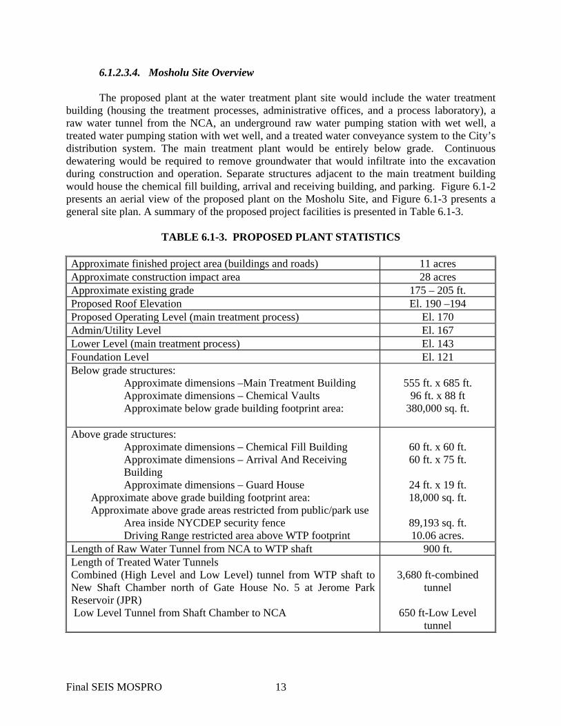
The proposed plant at the water treatment plant site would include the water treatment building (housing the treatment processes, administrative offices, and a process laboratory), a raw water tunnel from the NCA, an underground raw water pumping station with wet well, a treated water pumping station with wet well, and a treated water conveyance system to the City’s distribution system. The main treatment plant would be entirely below grade. Continuous dewatering would be required to remove groundwater that would infiltrate into the excavation during construction and operation. Separate structures adjacent to the main treatment building would house the chemical fill building, arrival and receiving building, and parking. Figure 6.1-2 presents an aerial view of the proposed plant on the Mosholu Site, and Figure 6.1-3 presents a general site plan. A summary of the proposed project facilities is presented in Table 6.1-3.
TABLE 6.1-3. PROPOSED PLANT STATISTICS Approximate finished project area (buildings and roads) 11 acres Approximate construction impact area 28 acres Approximate existing grade 175 – 205 ft. Proposed Roof Elevation El. 190 –194 Proposed Operating Level (main treatment process) El. 170 Admin/Utility Level El. 167 Lower Level (main treatment process) El. 143 Foundation Level El. 121 Below grade structures:
Approximate dimensions –Main Treatment Building Approximate dimensions – Chemical Vaults Approximate below grade building footprint area:
555 ft. x 685 ft.
96 ft. x 88 ft 380,000 sq. ft.
Above grade structures:
Approximate dimensions – Chemical Fill Building Approximate dimensions – Arrival And Receiving Building Approximate dimensions – Guard House
Approximate above grade building footprint area: Approximate above grade areas restricted from public/park use Area inside NYCDEP security fence Driving Range restricted area above WTP footprint
60 ft. x 60 ft. 60 ft. x 75 ft.
24 ft. x 19 ft. 18,000 sq. ft.
89,193 sq. ft. 10.06 acres.
Length of Raw Water Tunnel from NCA to WTP shaft 900 ft. Length of Treated Water Tunnels Combined (High Level and Low Level) tunnel from WTP shaft to New Shaft Chamber north of Gate House No. 5 at Jerome Park Reservoir (JPR) Low Level Tunnel from Shaft Chamber to NCA
3,680 ft-combined
tunnel
650 ft-Low Level tunnel
Final SEIS MOSPRO 13

Croton Water Treatment Plant
M&
E F
ile: P
:\E
nvi
ron
me
nta
l Qu
alit
y\C
roto
n\2
00
4 F
ina
l SE
IS\G
rap
hic
s\0
6-M
OS
\01
-PR
OD
ES
C\M
OS
-pro
de
scB
-05
-13
-04
.cd
r 0
6/2
1/0
4
PRIVILEGED AND CONFIDENTIAL
Aerial View of the Proposed Projectat the Mosholu Site
Figure 6.1-2

A VE W
GO
ULD
EN
Reservoir
MO
SH
OL
U
PK
WY
JER
OM
E
ReservoirHillview
RD.
VA
NC
RTLA
NDT
AreaRecreation
DEEG
AN
EX
PW
Y
MOSHO
LUPK
WY
O
DEEGAN
Jerome Park
Shandler
MAJOR
W.GUN HILL
VAN CORTLANDT PARK SOUTH
AVE.AV
E.
JE
RO
ME
AV
E.
BA
INB
RID
GE
AV
E.
E 234THST
E. 233RD ST.
VA
N
CORTLANDT
PARK E.
Van Cortlandt Park
Van Cortlandt Golf Course
Woodlawn Cemetery
Van Cortlandt Park
Temporary Club House
Temporary Club Parking
Location of the Proposed Croton Project at the Mosholu Site
Figure 6.1-3
Croton Water Treatment Plant
Not to Scale
M&
E file
: P
:\E
nvi
ron
me
nta
l Qu
alit
y\C
roto
n\2
00
4 F
ina
l SE
IS\G
RA
PH
ICS
\06
-MO
S\0
1-P
RO
DE
SC
\MO
S-p
rod
esc
C-0
5-2
5-0
4.c
dr
06
/28
/04
Proposed Building Footprint
Approximate Area Affected
During Constrution
LEGEND
Raw Water Tunnel
New
Cro
ton
Aqu
educ
t
Treated Water Tunnel

Process Laboratory. The proposed plant would include a process laboratory for
monitoring and controlling the treatment processes. The laboratory would be equipped to analyze a number of water quality parameters such as turbidity, color, pH, alkalinity, disinfectant residuals, particle counts, iron, and manganese. The laboratory would also process other samples for shipment to off-site laboratories for analysis. Several of these analyses use bench top analyzers, which would require a minimal amount of chemicals for sample preparation and instrument maintenance and calibration; the other analyses would be performed using colorimetric processes with commercially-prepared reagent packets. A summary of anticipated analytical chemical usage is presented in Table 6.1-4.
TABLE 6.1-4. PROCESS LABORATORY ANALYTICAL REQUIREMENTS AND WASTE DISPOSAL
ANALYSIS METHOD(1) REQUIRED REAGENTS QUANTITY
DAILY WASTE DISCHARGES
TYPE
DISPOSAL METHOD
Turbidity SM180.1 None Water Color SM204 None Water pH SM424 None Water Neutralizing
sink/sewer Alkalinity SM403 0.02 N
Sulfuric Acid Approx. 100 ml per sample per day
Solution Neutralizing sink/sewer
Particle Count Laser Diode Technology
None Water Sanitary Sewer
Iron SM310A FerroVer (2) Approx. 10 ml per sample per day
Solution Neutralizing sink/sewer
Manganese USEPA LR PAN Method
PAN indicator (3)
Alkaline Cyanide (4)
Ascorbic Acid
1ml – PAN 0.5ml – Alkaline 1 packet – Ascorbic (each per sample/day)
Solution Neutralizing sink/sewer
Chlorine Residual
SM409E None Solution
Cleaning Reagents
Nitric Acid (4%) Standard Detergent (Alconox)
5 gallons per year 10 gallons per year
Solution Neutralizing sink/sewer
Total Estimated Discharge Volume To Sewer Per Day 42 gal Notes: 1. SM – Standard method for the analysis of water and wastewater 2. FerroVer – Iron Phenanthroline
3. PAN Indicator – Dimethyl Formamide, Ammonium Acetate, Triton X, Water 4. Alkaline Cyanide – Water, Sodium Cyanide, Sodium Hydroxide
Final SEIS MOSPRO 16

Electrical Power. Energy conservation would be universally implemented in the design and operation of the proposed plant. Premium efficiency motors, pumps, transformers, lighting, and energy-consuming appliances would be specified as much as possible. Electric power for the proposed plant would be furnished by the New York Power Authority (NYPA), which has a contract to supply electricity to New York City government facilities. NYPA generates, buys, and transmits electrical power on a wholesale basis, but does not have its own distribution system. NYPA would supply electrical power through Consolidated Edison Company of New York’s existing distribution system (Con Edison). The distribution of electricity to the proposed plant at the water treatment plant site would be the responsibility of Con Edison. The electric supply for the proposed plant would be provided from the Washington Street Substation in Mount Vernon via a combination of overhead and underground feeders using triplexed shield cables. For a further description of the feeder route to the Mosholu Site, refer to Section 6.16, Infrastructure and Energy. Determination of the electrical power demands was estimated based on three scenarios: connected load, maximum demand, and average demand. The connected load is the sum total electrical load of all equipment installed in the facilities, including standby units that normally would not be operating. This amount is not used for supply capacity. Maximum demand is the total maximum demand of all electrical loads when the proposed plant is operating at its maximum flow capacity (290 mgd). Average demand is the total maximum demand of all electrical loads when the proposed plant is operating at its average flow capacity (144 mgd). Table 6.1-5 presents the estimated electrical power demands for these three scenarios. In addition, there would be an emergency power system to run emergency and safety equipment, but not to operate the proposed plant. Two diesel generators would provide the power for this emergency system.
TABLE 6.1-5. ESTIMATED ELECTRICAL POWER DEMANDS FOR THE PROPOSED PLANT
Estimated Electrical Load, kW Facilities Connected
Maximum Average Emergency Proposed Plant:
Pump Stations 22,788 16,361 9,505 27 Treatment Processes1 13,155 8,990 6,657 518 Residuals 572 555 395 72 Administration, HVAC, Service Areas
3,115 1,710 1,634 528
Total 39,630 27,616 18,191 1,145 Notes: 1. Treatment Processes includes filtration, Dissolved Air Flotation, electrical substation area, and Ultraviolet Light Disinfection.
The proposed plant at the water treatment plant site would require up to six underground service feeders, each at 13.2-kV. The Bronx is designated by Con Edison as a “second contingency” area, meaning that any two feeders may be taken out of service at any time and the remaining feeders must be able to carry the maximum demand load.
Final SEIS MOSPRO 17

Electrical Power Distribution. The electrical loads within the proposed plant would be divided into three groups: Train A – north side of the process loads; Train B – south side of the process loads; and common facilities – administration/maintenance areas, HVAC, and general use equipment. Both of the treatment process trains (Train A and Train B) could be operated or shut down independently of each other, or at the same time. The common facilities would be able to operate when either or both Trains A and B are running up to maximum capacity. In addition, any required components of the common facilities would be able to run when both treatment process trains are shut down. The main substation would receive the incoming underground service feeders and step down the voltage to 4.16-kV for distribution throughout the proposed plant. Power distribution feeders would be 4.16-kV-shielded cables in PVC-coated galvanized rigid steel conduits. Conduits would be run exposed in utility galleries from the main substation to the electrical rooms of major process areas. A medium-voltage switchgear (MVS) would distribute power to large motors and secondary unit substations (SUS). The SUS would further step down the voltage to feed 480-volt motor control centers (MCC), general process loads, and HVAC equipment. Dry type transformers would convert power from 480 volts to 240, 208 and 120 volts to supply power to lighting and small loads connected to lighting panel-boards.
Electrical Design Considerations. The basic electrical design considerations would be safety, reliability, flexibility, energy conservation, ease of operation and maintenance, and life cycle costs. The electrical design would comply with applicable Federal, State, City, and local codes and other applicable codes and standards. All major electrical equipment would be located indoors in dedicated electrical rooms. The underground and indoor installation of electrical facilities and the state of the art design, including shielding, would reduce electromagnetic fields and extremely low frequency emissions (EMF/ELF) to background levels in areas where the public would have access.
Emergency Power. In case all Con Edison feeders are out of service, two emergency diesel generators, each rated 1,500 kW, one operating and the other as backup, would provide emergency power. The generators would be available for fire pumps, fire alarm, fire protection, smoke purging exhaust fans, emergency elevators, and other emergency equipment in case of fire or other emergency conditions. Emergency power for the security system, communication systems, lightning protection system, plant control system and other safety equipment would also be provided. Treatment processes and pumping operations would be stopped until Con Edison power is restored. All process controls, and computer and communication systems would have individual uninterruptible power supplies (UPS). Batteries, chargers, and UPSs would be supplied with automatic transfers to the emergency generator. An underground fuel storage tank would be provided. The size of the fuel storage tank would be 3,000 gallons, based on 24 hours of continuous full-load operation of one generator.
Traffic Circulation. After construction is complete, access to the water treatment plant site would be off Jerome Avenue. A two-way road would provide access to the proposed plant and golf course facilities. The two-way road would branch into an access road to the public golf course parking area and to a loop access for the proposed plant. Access to the proposed plant
Final SEIS MOSPRO 18

loop would be controlled and secured from the public by means of a vehicle and pedestrian inspection facility and guard house. No access for gasoline-powered vehicles would be provided in the proposed plant after construction is complete and the facility is operational. Deliveries would be made through the Arrivals and Receiving Building. Employee parking facilities (42 spaces) would be located to the north of the Arrival and Receiving Building.
Architectural Considerations. Except for the Arrival and Receiving Building, Chemical Fill Building, emergency stair exits/ventilation structures, and golf course structures, the entire facility would be below finished grade. The architectural design for the above-grade building facades would place a high priority on aesthetics while responding to the requirements of the functional elements required by both the proposed plant as well as the recreational structures associated with the golf course. This would require a careful analysis and blend of materials to provide a harmonious contextual design while integrating the security, low maintenance, and long life needs of the water treatment plant. A selection of traditional materials suitable for both uses could include pre-cast concrete, stone or brick facing, concrete, ornamental metalwork, and metal roofing. Other materials may include high performance, pre-painted doors, windows, and louvers in selected colors to provide a complementary strong visual statement. Due to the unique life safety concerns related to underground buildings, additional active and passive fire safety features would be incorporated into the overall building design.
Areas of the Site that would require limited public access include the water treatment plant rooftop, which would be under the future driving range, and the approximately two-acre secure area north of the existing parking lot that would be used for NYCDEP parking, the chemical fill building, and the arrivals/receiving building. These areas would be restricted to vehicles by low stone walls or other structures such as the tee-boxes for the driving range along the east side of the driving range. The stone walls along the north and south sides would incorporate ventilation louvers and would serve as the foundation for a tall fence that would keep golf balls from leaving the driving range. The facades of the low stone walls would be designed to look like the existing rock walls along Jerome Avenue north of Gun Hill Road, although their internal construction would be designed to serve as a vehicle interdiction wall.
Department of Parks and Recreation Facilities. It is the intent of NYCDEP to share the
land required for the water treatment plant at the Mosholu Site with the NYCDPR to the fullest extent possible so that existing uses can continue into the future. The entrance road to the Mosholu Golf course would be improved but would remain in the existing location. The new road would fork approximately 350 ft. west of Jerome Avenue. The fork to the south would convey public traffic to a new club house and parking area near the driving range. The fork to the west would pass through a security checkpoint to a secure area of about two acres that would enclose the chemical fill station, arrivals/receiving building, and NYCDEP parking. This area would be screened from casual public view by a low stone wall or the natural topography that would serve to block vehicles, plantings and a fence. The current NYCDPR maintenance facility for the golf concessionaire consists of a pair of sheds west of the current parking area. These sheds are in poor repair. They would be replaced by a
Final SEIS MOSPRO 19

new facility located just north of their current location and adjacent to the NYCDEP secure area. Access to the driving range for NYCDPR maintenance of the driving range would be provided. 6.1.2.4. Treated Water Conveyance
The Croton System in the City consists of a three level service system: a High Level Service, an Intermediate Level Service and a Low Level Service10. Croton water is pumped into the Intermediate Level Service and High Level Service to maximize the use of Croton water when needed. The normal areas supplied by the Croton System are the Low Level Service areas in Manhattan and the Bronx. These areas are fed by gravity from the Jerome Park Reservoir. The pressure in these areas is controlled by the surface elevation of Jerome Park Reservoir (typically Elevation 131-133 ft MSL), less hydraulic losses in the transmission and distribution systems downstream of the reservoir. Croton water is conveyed to Manhattan through the NCA, downstream of the reservoir to Shaft No. 33 and from there through transmission mains. Croton water is conveyed from Jerome Park Reservoir to the East Bronx through Gate House No. 5 and to the South Bronx through Gate House No. 6. Regulators are used when necessary to release Intermediate and High Level Service area water into the Low Level areas, to meet peak demands. Currently, the Mosholu Pumping Station supplies the High Level Service and the Jerome Pumping Station supplies the Intermediate Level Service. Mosholu Pumping Station, which is located under Gate House No. 7, can pump up to 52 mgd of Croton water into Shaft No. 3 of City Tunnel No.1, High Level Catskill/Delaware service. The Jerome Pumping Station has the capacity to pump up to 50 mgd of Croton water into the Intermediate Level Service distribution for the Bronx. Under normal operation, two pumps operate conveying about 38 mgd to the system. The third pump serves as a spare. However, the existing pumping facilities for both pumping systems are in need of replacement. Under the proposed project, the Jerome Park Reservoir would remain in service as a raw water reservoir, and act as a balancing reservoir to meet the fluctuating water supply needs of the City. Treated water would be conveyed from the proposed plant to the High and Low Level Service Areas. A new shaft would be constructed west of the proposed plant to contain a new 9-foot diameter Low Level treated water conduit and a new 9-foot diameter High Level treated water conduit. A new combined treated water tunnel would be constructed from the bottom of this shaft at the water treatment plant site to a new shaft chamber located near Jerome Park Reservoir. This new tunnel would be approximately 3,680 feet long and would be sufficiently large enough to contain both a 9-foot diameter High Level Service treated water pipe and a 9-foot diameter Low Level Service treated water pipe between the shaft at the water treatment plant site and the new shaft chamber. Low Level treated water would flow to the pressurized NCA via a new treated 9-foot diameter tunnel to a new shaft chamber near Jerome Park Reservoir. From there a second new 9-foot
10 Levels (Low, Intermediate, and High) refer to the topographic height of the neighborhoods served. For example, Low Level Service includes low-level areas of the East and South Bronx and Manhattan. This water is transmitted through the distribution system at a lower level than the Intermediate and High Level Service. Intermediate Level Service would be provided from the High Level Service via existing regulators in the distribution system. Final SEIS MOSPRO 20

diameter Low Level tunnel would convey water to the NCA, downstream of Shaft No. 21. The new shaft chamber would convey Low Level treated water to Manhattan. At this new shaft chamber, the Low Level tunnel would reduce in size and contain an 8-foot diameter conduit. It is anticipated to be approximately 650 feet in length. The East Bronx would receive their Low Level Service water from a new 48-inch diameter pipe, which would be constructed from the new shaft chamber to the existing Valve Chamber “C.” The South Bronx would receive their Low Level Service water through a new Flow Meter “D,” which would connect to the existing 48-inch diameter service near Jerome Park Reservoir. Intermediate Level Service water would be supplied from the High Level Service, using existing pressure reducing valves and regulators. High Level Service water would be pumped from the water treatment plant wet wells through a new 9-foot diameter tunnel to the new shaft chamber near Jerome Park Reservoir. The water would be distributed from the new shaft chamber to City Tunnel No. 1, Shaft No. 3, and Shaft No. 4; and City Tunnel No. 3, Shaft No. 4B. A future connection would be constructed to convey an additional 155 mgd. An 84-inch diameter pipe would be constructed from the proposed plant to Jerome Avenue and stubbed. Existing trunk mains within Jerome Ave. would be replaced with larger diameter pipes to convey the additional flow and would connect to the proposed 84-inch diameter pipe. With the water treatment plant located at the Mosholu Site, distribution system redundancy would be provided by keeping the Croton and Catskill/Delaware Systems separated until after treatment. This redundancy would enable water to still be supplied to users in the event something were to occur to either the Croton or Catskill/Delaware System. In addition, this separation allows water to be delivered to both the high-level (the Catskill/Delaware System) as well as the low-level (the Croton System) service areas. The Mosholu Site would provide a connection to the high-level service in addition to the low-level service. 6.1.2.5. Treated Water Pumping Station
Treated water would leave the UV disinfection units and pass through the plant wet wells into the treated water pumping station. The station would consist of six treated water pumps; each pump would have a nominal capacity of 58 mgd. With five pumps in operation and one in standby the supply of the pumps would total 290 mgd. From the treated water pumping station, treated water would be conveyed through one of the distribution methods described below. In the event that the proposed plant is not in operation and treated water must still be distributed to the Low Level system, the treated water pumps would be provided with pressure reducing valves (PRV). Water from the Catskill and Delaware System would travel through the PRVs, and they would transfer treated water from the High Level system to the Low Level system. The PRVs would reduce the pressure by approximately 150 feet (65 psi). Each PRV would have a maximum capacity of 47.5 mgd for a total design flow of 190 mgd with four PRVs in operation.
Final SEIS MOSPRO 21
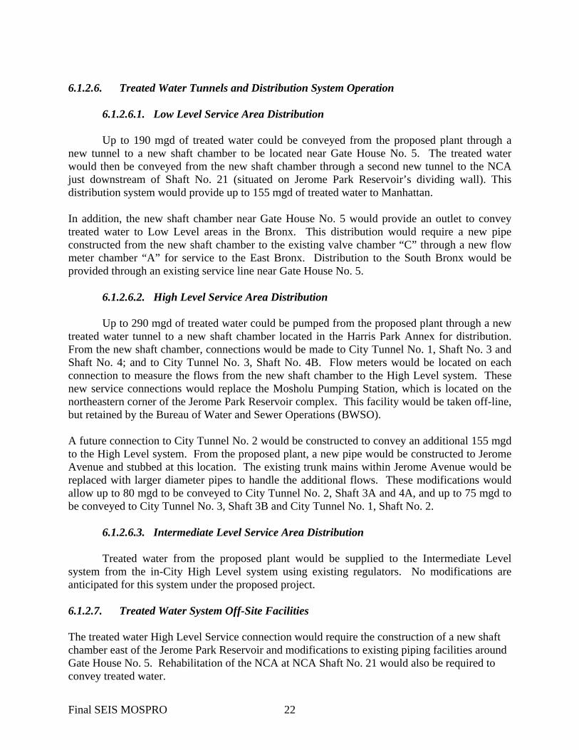
6.1.2.6. Treated Water Tunnels and Distribution System Operation
6.1.2.6.1. Low Level Service Area Distribution
Up to 190 mgd of treated water could be conveyed from the proposed plant through a new tunnel to a new shaft chamber to be located near Gate House No. 5. The treated water would then be conveyed from the new shaft chamber through a second new tunnel to the NCA just downstream of Shaft No. 21 (situated on Jerome Park Reservoir’s dividing wall). This distribution system would provide up to 155 mgd of treated water to Manhattan. In addition, the new shaft chamber near Gate House No. 5 would provide an outlet to convey treated water to Low Level areas in the Bronx. This distribution would require a new pipe constructed from the new shaft chamber to the existing valve chamber “C” through a new flow meter chamber “A” for service to the East Bronx. Distribution to the South Bronx would be provided through an existing service line near Gate House No. 5.
6.1.2.6.2. High Level Service Area Distribution
Up to 290 mgd of treated water could be pumped from the proposed plant through a new treated water tunnel to a new shaft chamber located in the Harris Park Annex for distribution. From the new shaft chamber, connections would be made to City Tunnel No. 1, Shaft No. 3 and Shaft No. 4; and to City Tunnel No. 3, Shaft No. 4B. Flow meters would be located on each connection to measure the flows from the new shaft chamber to the High Level system. These new service connections would replace the Mosholu Pumping Station, which is located on the northeastern corner of the Jerome Park Reservoir complex. This facility would be taken off-line, but retained by the Bureau of Water and Sewer Operations (BWSO). A future connection to City Tunnel No. 2 would be constructed to convey an additional 155 mgd to the High Level system. From the proposed plant, a new pipe would be constructed to Jerome Avenue and stubbed at this location. The existing trunk mains within Jerome Avenue would be replaced with larger diameter pipes to handle the additional flows. These modifications would allow up to 80 mgd to be conveyed to City Tunnel No. 2, Shaft 3A and 4A, and up to 75 mgd to be conveyed to City Tunnel No. 3, Shaft 3B and City Tunnel No. 1, Shaft No. 2.
6.1.2.6.3. Intermediate Level Service Area Distribution
Treated water from the proposed plant would be supplied to the Intermediate Level system from the in-City High Level system using existing regulators. No modifications are anticipated for this system under the proposed project. 6.1.2.7. Treated Water System Off-Site Facilities The treated water High Level Service connection would require the construction of a new shaft chamber east of the Jerome Park Reservoir and modifications to existing piping facilities around Gate House No. 5. Rehabilitation of the NCA at NCA Shaft No. 21 would also be required to convey treated water.
Final SEIS MOSPRO 22

6.1.2.7.1. Treated Water Tunnels and Shaft at the Water Treatment Plant
A new shaft would be constructed west of the water treatment plant to contain a new 9-
foot diameter Low Level treated water conduit and a new 9-foot diameter High Level treated water conduit. A new combined treated water tunnel would be constructed from the bottom of this shaft at the water treatment plant site to a new Shaft Chamber located just north of Gate House No. 5. This new tunnel would be approximately 3,680 feet long and be sufficiently large enough to contain both a 9-foot diameter High Level service treated water pipe and a 9-foot diameter Low Level service treated water pipe between the shaft at the water treatment plant site and the new Shaft Chamber located near Gate House No.5. At the new Shaft Chamber, the Low Level tunnel would reduce in size and connect to the NCA downstream of Shaft No. 21 to convey Low Level treated water to Manhattan. This tunnel is anticipated to be approximately 650 feet in length and contain an 8-foot diameter conduit.
6.1.2.7.2. Shaft Chamber
A new Shaft Chamber would be constructed below ground in the Harris Park Annex near the Jerome Park Reservoir. The new Shaft Chamber would provide a central point for distributing treated water to the High and Low Level services. High Level treated water from the water treatment plant would be conveyed through a 9-foot diameter tunnel. The new Shaft Chamber would be located on top of a 9-foot diameter and a 4-foot diameter shaft terminating at Elevation 90 feet. The new Shaft Chamber would convey High Level water via two 48-inch diameter pipes to City Tunnel No. 1, Shaft No. 3. High Level water would also be conveyed from the new Shaft Chamber through a new 96-inch diameter pipe to City Tunnel No. 3, Shaft No. 4B and City Tunnel No. 1, Shaft No. 4 via new 84-inch and 48-inch diameter pipes connecting to the existing Valve Chamber “A.” Low Level treated water would also be conveyed from the new Shaft Chamber. A new 8-foot diameter tunnel would continue from the new Shaft Chamber and connect to the NCA to convey Low Level treated water to Manhattan via the NCA (downstream of Shaft No. 21). A new 48-inch diameter pipe would also be constructed from the new Shaft Chamber to the existing Valve Chamber “C” to deliver Low Level treated water to the East Bronx. A connection from the new Shaft Chamber to the existing 48-inch diameter service in the vicinity of Gate House No. 5, which continues along the floor of the south basin of the Jerome Park Reservoir, would convey Low Level treated water to the South Bronx.
6.1.2.7.3. Low Level Treated Water Tunnel from the new Shaft Chamber to the NCA
Low Level treated water would be conveyed from the new Shaft Chamber to the NCA by gravity flow through an approximately 650-foot long, 8-foot diameter tunnel. The tunnel would connect to the NCA downstream of Shaft No. 21 and would slope down towards the NCA. The invert elevation at the new Shaft Chamber would be at Elevation 8.5 feet, approximately 125 feet below grade. The new Low Level treated water tunnel would be designed to match the invert elevation of the NCA at this location (approximately Elevation 6.30 feet). Rock dowels and welded wire fabric
Final SEIS MOSPRO 23

would be used to support the rock at the point of connection. During preliminary design, appropriate strategies to enable tunnel dewatering and venting would be developed.
6.1.2.7.4. Work on Piping around Gate House No. 5
Flow Meter Chamber “A.” The function of the proposed Flow Meter Chamber “A” would be to measure flows from the new Shaft Chamber to the East Bronx Low Level service and to the South Bronx Low Level service. The proposed chamber would be an underground concrete vault containing two 48-inch diameter flow meters. The proposed Flow Meter Chamber “A” would be located approximately 330 feet north of Gate House No. 5. A new 48-inch diameter pipe would be constructed from the proposed chamber to the existing Valve Chamber “C” to connect to the East Bronx Low Level service. A second new 48-inch diameter pipe would be constructed to an existing butterfly valve that connects to the South Bronx Low Level service just north of the dividing wall.
Flow Meter Chamber “B.” The function of the proposed Flow Meter Chamber “B” would be to measure flows from the new Shaft Chamber to City Tunnel No. 1, Shaft No. 3 High Level service and other existing High Level service connections. The proposed chamber would be an underground concrete vault containing two 48-inch flow meters. The proposed Flow Meter Chamber “B” would be located approximately 480 feet north of Gate House No. 5. The proposed Flow Meter Chamber “B” would connect to new 48-inch diameter pipes on south side of the chamber (from the new Shaft Chamber) and to existing 48-inch diameter High Level service pipes on the downstream (north) side.
Flow Meter Chamber “C.” The function of the proposed Flow Meter Chamber “C” would be to measure flows from the new Shaft Chamber, via the existing Valve Chamber “A” to High Level service to City Tunnel No. 1, Shaft No. 4 and City Tunnel No. 3, Shaft No. 4B. The proposed chamber would be an underground concrete vault, containing one 84-inch and one 48-inch flow meter. The proposed Flow Meter Chamber “C” would be located at the intersection of Goulden Avenue and W. 205th Street. The proposed Flow Meter Chamber “C” would connect to existing 84-inch (to Shaft No. 4B) and 48-inch diameter (to Shaft No. 4) pipes on both the upstream and downstream sides of the Chamber.
Valve Chamber “A.” The existing Valve Chamber “A” is located north of the intersection of Goulden Ave. and W. 205th Street. The 48-inch and 84-inch diameter High Level service pipes connect to City Tunnel No. 1, Shaft No. 4 and City Tunnel No. 3, Shaft No. 4B, respectively. Proposed modifications include:
• Remove the existing 48-inch interconnection and butterfly valve between the 48-inch and 84-inch diameter pipes and replace with blind flanges
• Close the existing 48-inch butterfly valve located on the 48-inch reinforced concrete water main that services City Tunnel No. 1, Shaft No. 3. Remove a section of the 48-inch pipe to install the connection from the new Shaft Chamber to the new Flow Meter Chamber B and construct a bulkhead south of the connection.
Valve Chamber “C.” The existing Valve Chamber “C” is located just east of Gate House
No. 5. Under proposed modifications, the valve chamber would receive Low Level service water
Final SEIS MOSPRO 24

from the new Shaft Chamber on Goulden Ave via new Flow Meter A and would supply water to the East Bronx via two 36-inch mains. Proposed modifications include:
• Remove the existing section of each of the 48-inch diameter pipes on the west side of the chamber and place a blind flange on each pipe; This would separate the distribution system from Gate House No. 5
• Cap the existing 48-inch suction line to the Jerome Pumping Station just east of the pumping station.
6.1.2.7.5. Jerome Park Reservoir
Jerome Park Reservoir is an open distribution reservoir with a concrete bottom covering
approximately 93 acres, formed principally of stone-masonry walls and earth embankment. In the proposed project, Jerome Park Reservoir would be used as a raw water reservoir. A new shaft chamber and flow meter chambers mentioned herein before would be installed near the Jerome Park Reservoir as well as additional work that are required to maintain the facilities around Jerome Park Reservoir.
6.1.2.7.6. Gate House No. 7/ Mosholu Pumping Station
Gate House No. 7 is located along the northeast corner of Jerome Park Reservoir at the intersection of Sedgwick and Goulden Avenues, in the Bronx, New York. In the proposed project, Gate House No. 7 would be utilized to either control flow directly into the north basin of Jerome Park Reservoir or to allow water to continue through the New Croton Branch Aqueduct. Gate House No. 7 would no longer discharge water to the Mosholu Pumping Station or continue to be used as the chlorination facility. Therefore, the electrical and chemical equipment and piping systems, and all equipment from the switchgear rooms related to the pumping station would be removed. The superstructure would require interior and exterior rehabilitation and the sluice gates in the west portal of the north basin would be refurbished and automated. The Mosholu Pumping Station is contained within the Gate House No. 7 complex. In the proposed project, the 75-year-old Mosholu Pumping Station would be taken off line and all connections to the distribution system and the access pipe from Jerome Park Reservoir to Gate House No. 7 would be plugged, sealed, and equipment would be removed. New piping and flow meters would connect the two shaft risers in Shaft No. 3 with the two 48-inch diameter High Level Service transmission mains outside the new Shaft Chamber on Goulden Avenue.
Final SEIS MOSPRO 25

6.1.2.7.7. Gate House No. 5
Gate House No. 5 is located on the east side of the reservoir, near the intersection of Goulden Avenue and West 205th Street. In the proposed project, a potassium permanganate facility would be constructed within Gate House No. 5 if it were deemed necessary in the future. This would entail placing plastic bins and mixing equipment in an area where some existing equipment would be removed11.
6.1.2.7.8. New Croton Aqueduct Shaft No. 21
NCA Shaft No. 21 is located in the north basin of Jerome Park Reservoir. In the proposed project, NCA Shaft No. 21 would direct raw water from Jerome Park Reservoir to the proposed plant via the NCA. Minor rehabilitation work is probable but no modifications to the facility at NCA Shaft No. 21 are proposed at this time.
6.1.2.7.9. Gate House No. 6 / Microstrainer Building
The Gate House No. 6 building and Microstrainer Building are located at the southern edge of the Jerome Park Reservoir at the intersection of Reservoir Avenue and Goulden Avenue. In the proposed project, Gate House No. 6 would be taken off line and the connections from the gate house to the bypass piping and the two inlet pipes from the Jerome Park Reservoir would be plugged. Gate House No. 6 would be retained for BWSO use, but all of the operating equipment would be removed. The Microstrainer Building would be dismantled, and the area would be landscaped and kept open for a potential access ramp to the reservoir.
6.1.2.7.10. Gate House No. 3
Gate House No. 3 is a one-story, 30-foot by 33-foot building located on the west side of the south basin of the reservoir. In the proposed project, Gate House No. 3 would continue to function as a water intake structure. The interior and exterior of the structure would be rehabilitated. Two 48-inch diameter gate valves to the distribution system would be removed and the operating stems would be cut. Concrete plugs at the gate valves would be constructed.
6.1.2.7.11. Gate House No. 2
Gate House No. 2 is located in the north basin of Jerome Park Reservoir. In the proposed project, Gate House No. 2 would continue to serve as the main drainage facility for both basins of the reservoir and supply water to Gate House No. 5. A new overflow facility for the north basin would also be installed in Gate House No. 2. The interior and exterior of the structure would be rehabilitated. The 48-inch diameter gate valve to the distribution system would be
11 The NYDEP has committed to removing the existing gaseous chlorination equipment from Gate House No. 5 as part of its Risk Management Plan. This work is anticipated for 2004, prior to the start of the Croton Water Treatment Plant project, and is being evaluated as a separate environmental review. It would be completed irrespective of the choice of sites for the Croton Water Treatment Plant. It involves removing the gaseous chlorine tanks and replacing them with liquid sodium hypochlorite equipment. Final SEIS MOSPRO 26

closed and the operating stem would be cut. A concrete plug at the gate valve would be constructed. A new overflow weir in the gate house would be constructed to independently control water levels in the north basin. Additionally, a 30-inch drain line would be extended from the dividing wall approximately 700-feet to Gate House No. 2, where it would be connected to an existing drain. The extension would allow the south basin to be drained without having to utilize the present method of using a diver to remove the blind flange to the drain inlet located on the reservoir floor.
6.1.2.7.12. Jerome Pumping Station
The Jerome Pumping Station is located on Jerome Avenue between Mosholu Parkway and West 205th Street in the Bronx. In the proposed project, the Intermediate Level service would be supplied from the in-City High Level Service using existing pressure reducing valves and regulators. The Jerome Pumping Station would no longer be needed and would be taken off line, but would be retained for BWSO use. All the mechanical equipment, suction mains and discharge mains would be capped at the face of the building. A portion of the water treatment plant staff may occupy the Jerome Pumping Station. Future use of the Jerome Pumping Station would be the subject of further study.
6.1.2.7.13. Emergency Bypass
If the proposed plant is taken out of service and the Croton Water Supply is required to
meet demand, subject to NYSDOH approval, untreated Croton water could be fed into the distribution system at Jerome Park Reservoir through the plug in the NCA that would then convey Low Level water to Manhattan.
6.1.2.8. Solids Handling
Treatment of Croton Water would result in the production of residuals throughout the treatment process. Separating, handling, and managing these residuals would allow reclamation of usable water and minimization of residuals waste disposal.
The residuals handling facility would serve to reclaim filter-to-waste water (e.g. water wasted during the start-up of a filter after backwashing), and waste backwash water. The reclaimed wastewater would be recycled to the head of the plant for treatment. The floated coagulated material from the DAF (Dissolved Air Floatation) process used by the proposed plant would flow to the floated solid storage tanks. Floated solids and sedimentation from the filter-to-waste and waste backwash water would also be directed to the floated solid storage tanks. The design average and maximum mixed solids flow rates of 2 percent solids would be approximately 121,000 gallons per day (gpd) and 284,000 gpd, respectively.
There will be no residuals treatment on-site at the Mosholu Golf Course Site. The residuals collected would be transferred from the storage tanks to the Hunts Point Water Pollution Control Plant for dewatering and disposal. Hunts Point is located in The Bronx, NY southeast of the proposed water treatment plant site. The mixed solids from the floated solids storage tanks would be pumped through two proposed six-inch force mains (each would be able to handle the maximum flow) to the Hunts Point WPCP, which is located in the South Bronx, NY,
Final SEIS MOSPRO 27

approximately seven miles from the water treatment plant site. The solids would be dewatered at the Hunts Point WPCP dewatering facility.
There are three solids storage tanks at the Hunts Point WPCP, which receives flow from Newtown Creek WPCP and the Hunts Point WPCP. The quantity of mixed solids from the proposed plant would not compromise these storage tanks or the dewatering facilities at the Hunts Point WPCP. The Hunt Points WPCP dewatering facility maintains 13 centrifuges, each with a capacity of 250 gallons per minute (gpm). Typically, the centrifuges are operated four to nine at a time with a combined capacity of 1,000 gpm to 2,250 gpm, depending on the amount of received. The maximum flow of 197 gpm of mixed solids from the proposed plant would not impact the operation of these centrifuges.
Final SEIS MOSPRO 28