final report subsoil investigation for proposed …ceb.intnet.mu/documents/prod3406_final subsoil...
TRANSCRIPT

FINAL REPORT
SUBSOIL INVESTIGATION FOR PROPOSED OFFICE BUILDING
AT FORT VICTORIA POWER STATION, PORT LOUIS, MAURITIUS
(RFQ NO: Q10836)

FINAL REPORT SUBSOIL INVESTIGATION FOR PROPOSED OFFICE BUILDING
AT FORT VICTORIA POWER STATION, PORT LOUIS, MAURITIUS
(RFQ NO: Q10836)
Prepared for: CENTRAL ELECTRICITY BOARD, PO Box 40, Royal Road, Curepipe,
Mauritius.
Prepared by:
Consulting Geotechnical Engineers & Geoscientists Tel: (230) 290 1350, Email:[email protected]
www.geocrust.com On Behalf of
GEOCONSUL LTEE Basing Rise, Calodyne, Grand Gaube,
Mauritius. Tel: (230) 288 1664, Fax : (230) 288 1772, Cell: (230) 253 2241
www.geoconsulmaurice.com
Submitted on July 24, 2012 Revision
No. Issued date
Issued by
Descriptions Prepared by
Reviewed & Approved by
0 June 13 / 2012
GC Preliminary Subsoil Investigation Report for comment
GK CA 1 July
24/2012 Final Subsoil Investigation
Report GK CA
July 24, 2012
Project Manager, Central Electricity Board, PO Box 40, Royal Road, Curepipe, Mauritius Attention : Mr. France NG Mr. Denis Thondajee Dear Sir/Madam:
GEOCONSUL LTEE has completed the authorized geotechnical investigation for the above referenced project based on the agreed scope of work. The enclosed final factual report described in details the investigation procedures for geotechnical Investigations, the findings to be utilized in the design of proposed office building and associated structure development at above project site.
We appreciate this opportunity to be of service to you in preparing this geotechnical investigation report. If there are any questions regarding the information contained in this report, or with respect to any work performed to date, please do not hesitate to contact us. Yours very truly, GEOCONSUL LTEE Robert Jean Luc UManaging Director Enclosure: Final Subsoil Investigation Report for above project Distribution to Client: Electronic PDF copy by email & Hard bound copies by mail/person
Geoconsul Ltée –Basing Rise, Calodyne, Grand Gaube, Mauritius. Tel: (230) 288 1664, Fax : (230) 288 1772, Cell: (230) 253 2241
Website : www.geoconsulmaurice.com
RE:
FINAL REPORT : Subsoil Investigation for Proposed Office Building at Fort
Victoria Power Station, Port Louis, Mauritius (RFQ NO: Q10836)

CLIENT: CENTRAL ELECTRICITY BOARD PREPARED BY: GEOCRUST LTD - CONSULTING GEOTECHNICAL ENGINEERS & GEOSCIENTISTS ON BEHALF OF GEOCONSUL LTEE
I (Table of Content)
FINAL REPORT: Subsoil Investigation for Proposed Office Building at Fort Victoria Power Station, Port Louis,
Mauritius (RFQ NO: Q10836)
TABLE OF CONTENTS
Section Descriptions Page No.
1.0 INTRODUCTION………………………………………………………………………….............. 1-2
1.1 OBJECTIVES & SCOPE OF THE WORK………………………………………............................. 1
1.2 PROJECT DETAILS & PROPOSED CONSTRUCTION……………………………………………… 1
1.3 PROJECT SITE LOCATION ………………………………………………………………............. 2
1.4 DESKTOP STUDY (REGIONAL GEOLOGY OF THE SITE)………………………………………… 2
2.0 SITE INVESTIGATION PROGRAM ….……………………………………………………….……. 3-4
2.1 COREHOLE DRILLING………………………………………................................................... 3
2.2 EXPLORATORY TRIAL PIT.…………………………………................................................... 3
2.3 SAMPLING FOR LABORATORY TESTINGS………………………….......................................... 3-4
2.4 IN-SITU TESTINGS IN COREHOLES………………………….................................................... 4
2.4.1 STANDARD PENETRATION TEST…………………………....................................................... 4
3.0 GROUNDWATER CONDITIONS……………………………………………………………………. 5
4.0 SUBSURFACE CONDITIONS AND CHARACTERISTICS OF STRATA……………………………… 5-6
5.0 LABORATORY TESTINGS……………………………………………………………………. 7-8
6.0 GUIDELINE FOR DESIGN CONSIDERATIONS AND DISCUSSIONS…..……………………………… 9-12
7.0 CONCLUSIONS …………………. …..…………………………………………………………. 13
8.0 REFERENCES ……………………. …..…………………………………………………………. 14
9.0 CLOSURE….……………………………………………………………………………………… 14
LIST OF APPENDICES
Appendix A Figures: Location of project site, Land use Map, Geological Map, Soil Map and Layout of Borehole as well as Trial Pit Locations
Appendix B Geotechnical Logs of Boreholes, Trial Pits and Photographs Appendix C Laboratory Test Results of Soil and Groundwater Samples

CLIENT: CENTRAL ELECTRICITY BOARD PREPARED BY: GEOCRUST LTD - CONSULTING GEOTECHNICAL ENGINEERS & GEOSCIENTISTS ON BEHALF OF GEOCONSUL LTEE
Page 1 of 14 FINAL REPORT: Subsoil Investigation for Proposed Office Building at Fort Victoria Power Station, Port Louis,
Mauritius (RFQ NO: Q10836)
1.0 INTRODUCTION This final report presents the results of geotechnical investigation conducted by GEOCONSUL LTEE during May 09–June 05, 2012 for the proposed office building construction at Fort Victoria power station. The consulting geotechnical engineering services of GEOCRUST LTD (Consulting Geotechnical Engineers & Geoscientists) were retained by GEOCONSUL LTEE to carry out a geotechnical investigation report preparation services for the proposed future development. This geotechnical report summarizes the results of the site investigations and in-situ testing carried out on behalf of our client CENTRAL ELECTRICITY BOARD (CEB). This report is being written to provide guidelines for foundation design. The tests and terminologies used in this report are according to BS1377: 1990 and BS5930: 1999. The site investigations generally follow accepted practices for geotechnical engineering. The format and contents are guided by the client specific needs and economics. Presented herein are the results of our factual findings concerning the work carried out [such as subsoil conditions and groundwater condition] from three (3) rotary core hole drilling, one (1) exploratory trial pit excavation and In-situ test- Standard Penetration Test in accordance with agreed scope of works. 1.1 Objectives and Scope of Works The subsoil investigation is intended to provide factual information of the ground and sub-strata conditions for proposed development. In order to accomplish these objectives, the following scopes of work have been performed:
• Drilling of three (3) Nos. rotary core hole at proposed development site; • Excavation of one (1) No. Trial Pit; • In-Situ Tests such as Standard Penetration Tests in the core holes; • Preparation of geotechnical logs; • Engineering classification of soil/rock; • Evaluation of bearing Capacity of foundation and engineering recommendations;
and • Provide factual subsoil investigation report includes ground profile, engineering
classification of soil/rock, and recommendation based on our proposed present scope of work.
The geotechnical site investigation was carried out as per “Code of Practice for Site Investigation - BS 5930:1999”. 1.2 Project Details and Proposed Construction The project details and proposed constructions were not provided during the geotechnical site investigation. We assumed that the proposed future development will consist of light to medium loaded conventional low rise building office building (2 storeys) with access roads and above clustered parking lots.

CLIENT: CENTRAL ELECTRICITY BOARD PREPARED BY: GEOCRUST LTD - CONSULTING GEOTECHNICAL ENGINEERS & GEOSCIENTISTS ON BEHALF OF GEOCONSUL LTEE
Page 2 of 14 FINAL REPORT: Subsoil Investigation for Proposed Office Building at Fort Victoria Power Station, Port Louis,
Mauritius (RFQ NO: Q10836)
1.3 Project Site Location The project site is located within CEB Fort Victoria Power Station Site, Port Louis, Mauritius. The general location of the site is presented in Figure 1 (Appendix A): Vicinity Map with aerial view (Using Google SPOT IMAGE) and Figure 2 (Appendix A): Land use Map.
1.4 Desktop Study (Regional Geology of the Site)
The island of Mauritius is of volcanic origin and formed by several series of basaltic rock of volcanic activities. Intermediate and more recent series of volcanic eruptions from several small emissions of volcanic rock distributed over the whole island cover the ancient central volcanic plateau and the deeply eroded valleys heading to the sea. Most of the island is now covered with the intermediate and late flows which have in general a gentle dipping towards the sea from the interior of the island. Isolated remnants of the initial ancient series occur in the highest peak of the island.
The lava flows consist of a sequence of massive basalt strata with vacuolar (vesicular) strata and volcanic breccias on top. Volcanic tuff layers occurs in-between the lava flows. The prevailing rock is a fine grained, dark to light grey, hard to very hard basalt often with intrusions of variable chemical composition. The vesicular strata have sometimes vesicles which are filled with calcite, zeolite or aragonite.
Overburdens are in-situ residual soil or colluviums, i.e. transported hill wash of completely weathered basaltic rock. Alluvial deposits which can be found rarely along some rivers are particular sand and gravel of eroded and transported basalt fractures. Occasionally alluvial clayey soil is to be found in some river valleys.
The region of Port Louis is characterised by a post volcanic period of erosion and deposition during which deep erosion channels radiating from the mountain rangers surrounding Port Louis were cut in the basaltic rock, resulting in significant variations of the depth to sound rock on plan. Detrital formations are encountered either deep below or underlying the base of volcanic flows.
The project site under ground investigation belongs to intermediate volcanic formation. The geological map (Giorgi, Loicc-1999) presented in the Figure 3 (Appendix A), which shows location of project site. The project site consists of Low Humic Latosols Soils (Published Notes on the 1:100,000 soil map of Mauritius by parish et. al 1965) is presented in Figure 4 (Appendix A). The exploratory core hole as well as trial pit subsurface strata confirmed the geological and soil profile described in the published records.

CLIENT: CENTRAL ELECTRICITY BOARD PREPARED BY: GEOCRUST LTD - CONSULTING GEOTECHNICAL ENGINEERS & GEOSCIENTISTS ON BEHALF OF GEOCONSUL LTEE
Page 3 of 14 FINAL REPORT: Subsoil Investigation for Proposed Office Building at Fort Victoria Power Station, Port Louis,
Mauritius (RFQ NO: Q10836)
2.0 SITE INVESTIGATION PROGRAM The subsoil investigation consisted of exploratory rotary core hole drilling, exploratory excavation (trial pit) and In-situ test (Standard Penetration Test). A general description of the present scope of work carried out is presented in the following sections. The layout plan of exploratory rotary core holes as well as exploratory trial pits in conjunction with this investigation is also presented on Figure 5 (Refer to Appendix A): Site Location Plan. The field investigations performed is shown in the Table 1.
Table 1: Details of Field Investigation Performed
2.1 Corehole Drilling The borehole was drilled by using drilling rig APAFOR 560 at the project site. The coring in soil and rocks were carried out using triple tube core barrel (NMLC-diameter of hole 76 mm) by rotary core drilling method. All drilling in soil as well as rock were followed by NX casing. The logging of rock cores with core photographs were carried out by professional geotechnical engineer – engineering geologist in accordance with “Geological Society Engineering Group Working Party Report on The Logging of Rock Cores for Engineering Purposes” &“Code of Practice for Site Investigation: BS 5930”. The detailed core hole logs are shown in Appendix B.
2.2 Exploratory Test Pit One trial pit was excavated on the project site using excavator JCB 3CX and using hammer when rocky mass encountered during excavation. The exposed subsoil were inspected and logged after completion of excavation. The logging of subsoil profiles were carried out by professional geotechnical engineer – engineering geologist in accordance with “Geological Society Engineering Group Working Party Report on The Logging of Rock Cores for Engineering Purposes” &“Code of Practice for Site Investigation: BS 5930”. The geotechnical logs of trial pit together with photographs are shown in Appendix B.
2.3 Sampling for Laboratory Test The size and quantity of soil/rock samples and frequency of sampling was performed based on purpose of investigation as well as client’s need and economics. The sampling was carried out in accordance with the BS standard, in the indicated range as mentioned in Table 2 and Appendix C.
Test Hole/Test Pit Locations
Depth of Drilling/Trial
pit (m)
NX Casing/Support
Depth (m)
In-situ Test
BH-1 14.80 8.0 3 Nos. of SPT BH-2 15.00 10.0 3 Nos. of SPT BH-3 15.00 5.3 2 Nos. of SPT TP-1 2.7 Not applicable -

CLIENT: CENTRAL ELECTRICITY BOARD PREPARED BY: GEOCRUST LTD - CONSULTING GEOTECHNICAL ENGINEERS & GEOSCIENTISTS ON BEHALF OF GEOCONSUL LTEE
Page 4 of 14 FINAL REPORT: Subsoil Investigation for Proposed Office Building at Fort Victoria Power Station, Port Louis,
Mauritius (RFQ NO: Q10836)
Table 2: Sampling Schedule for Laboratory Study
Location Trial Pit
Laboratory Test of Soil & Groundwater Samples
BH-1 @4.00-5.00m : Moisture Content & Atterberg Limit BH-2 @5.10-5.60m : Moisture Content & Chemical Analysis of Water
Sample BH-3 @5.30-5.80m : Moisture Content TP1 @1.10-1.20m : CBR (Soaked and Unsoaked), Moisture Content,
Atterberg Limit including PSD & Hydrometer
2.4 In-situ Testing in Corehole 2.4.1 Standard Penetration Test Standard penetration tests were carried out (in accordance with the requirements of BS1377: Part 9:1990) by driving a 50mm split spoon by means of a 63.5kg hammer falling a distance of 760mm. The SPT blow count N is the number of blows required to drive the spoon by 300mm after initially seating the spoon by 150mm.The SPT tests where the full penetration of 450mm could not achieved after 51 blows are termed as REFUSAL (RF). The details of SPT data are included in the Appendix B (Corehole Logs and core photographs) and Table 3.
Table 3: Summary of Standard Penetration Test Results Below existing ground surface (m)
Test Hole Test Depth
(m) N-Value
BH-1
1.5 Refusal
4.0-4.5 10
8.0-8.5 23
BH-2
1.0 Refusal
5.1-5.6 14
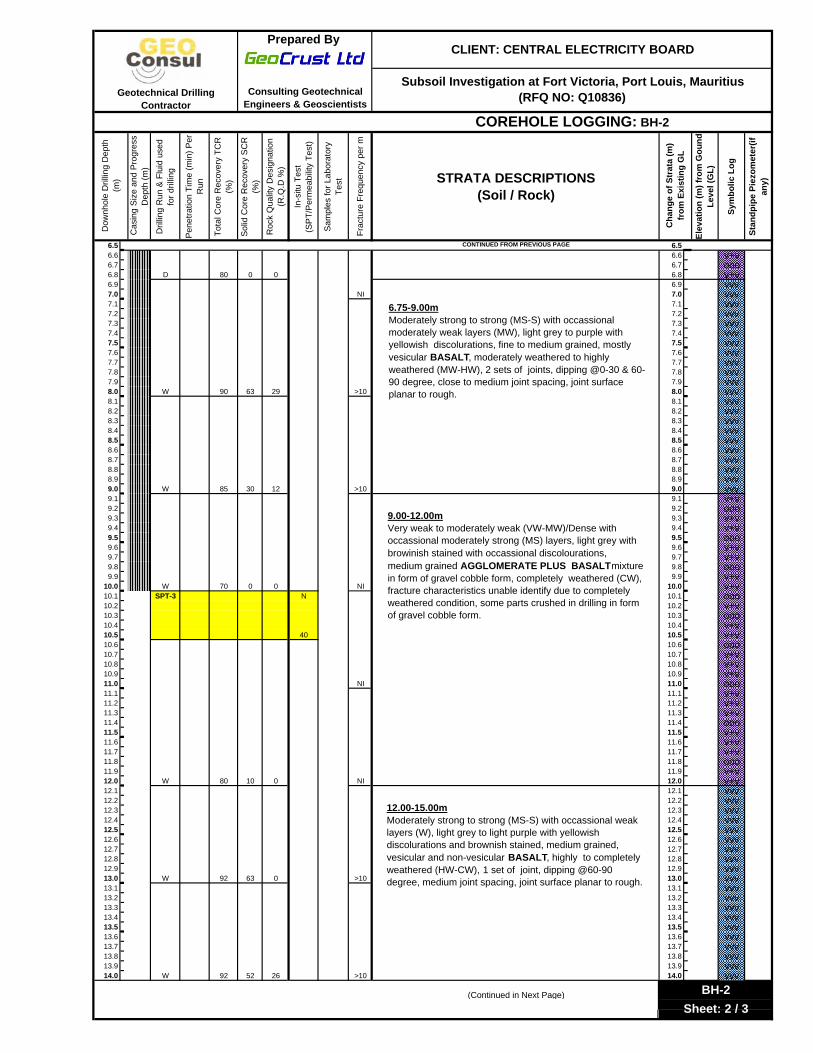
10.0-10.5 40
BH-3
1.0-1.5 43
5.3-5.8 33
CLIENT: CENTRAL ELECTRICITY BOARD PREPARED BY: GEOCRUST LTD - CONSULTING GEOTECHNICAL ENGINEERS & GEOSCIENTISTS ON BEHALF OF GEOCONSUL LTEE
Page 5 of 14 FINAL REPORT: Subsoil Investigation for Proposed Office Building at Fort Victoria Power Station, Port Louis,
Mauritius (RFQ NO: Q10836)
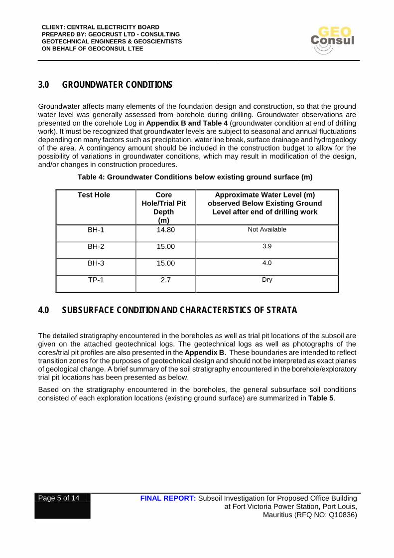
3.0 GROUNDWATER CONDITIONS
Groundwater affects many elements of the foundation design and construction, so that the ground water level was generally assessed from borehole during drilling. Groundwater observations are presented on the corehole Log in Appendix B and Table 4 (groundwater condition at end of drilling work). It must be recognized that groundwater levels are subject to seasonal and annual fluctuations depending on many factors such as precipitation, water line break, surface drainage and hydrogeology of the area. A contingency amount should be included in the construction budget to allow for the possibility of variations in groundwater conditions, which may result in modification of the design, and/or changes in construction procedures.
Table 4: Groundwater Conditions below existing ground surface (m)
Test Hole Core Hole/Trial Pit
Depth (m)
Approximate Water Level (m) observed Below Existing Ground
Level after end of drilling work
BH-1 14.80 Not Available
BH-2 15.00 3.9
BH-3 15.00 4.0
TP-1 2.7 Dry
4.0 SUBSURFACE CONDITION AND CHARACTERISTICS OF STRATA
The detailed stratigraphy encountered in the boreholes as well as trial pit locations of the subsoil are given on the attached geotechnical logs. The geotechnical logs as well as photographs of the cores/trial pit profiles are also presented in the Appendix B. These boundaries are intended to reflect transition zones for the purposes of geotechnical design and should not be interpreted as exact planes of geological change. A brief summary of the soil stratigraphy encountered in the borehole/exploratory trial pit locations has been presented as below.
Based on the stratigraphy encountered in the boreholes, the general subsurface soil conditions consisted of each exploration locations (existing ground surface) are summarized in Table 5.

CLIENT: CENTRAL ELECTRICITY BOARD PREPARED BY: GEOCRUST LTD - CONSULTING GEOTECHNICAL ENGINEERS & GEOSCIENTISTS ON BEHALF OF GEOCONSUL LTEE
Page 6 of 14 FINAL REPORT: Subsoil Investigation for Proposed Office Building at Fort Victoria Power Station, Port Louis,
Mauritius (RFQ NO: Q10836)
Table 5: Subsurface Soil/Rock Depth Intervals below existing ground surface (m)
Test
Hole/Trial Pit
GRAVELLY SILT/SILTY GRAVEL
with Uncontrolled
fill
CLAYEY SILT with occasional cobbles from basalt / Gravelly Clay
Moderately strong to strong, highly
weathered Basalt Boulder in the Matrix
of Clayey Silt
Moderately strong to strong
occasional weak layers, vesicular to non-vesicular fine to medium grained
BASALT ROCK highly weathered.
Very weak to weak and occasional
moderately strong, fine to medium
grained BASALT PLUS
AGGLOMERATE MIXTURE, highly
weathered to completely weathered
(Range in m from Ground Level)
BH-1 0.00-1.10 1.10-1.41 1.41-3.90 5.40-7.34 11.40-14.80
3.90-5.40 7.34-11.40
BH-2 0.00-1.00 - 1.00-4.55 6.75-9.00 12.00-15.00
4.55-6.75 9.00-12.00
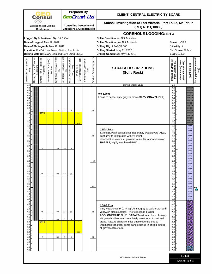
BH-3 0.00-1.50 - 1.50-4.50 6.31-8.27 10.30-15.00
4.50-6.31 8.27-10.30
TP-1 0.00-0.30 0.30-1.00
1.00-1.20 (Gravelly Clay)
1.20-2.70 - -
For the purpose of foundation design, the subsoil ground profile is presented on the basis of the stringent case as follows:
0.0-1.50m: Uncontrolled fill-Loose to Medium Dense or firm to stiff consistency
1.50-2.50m: Strong, greyish to brown, vesicular BASALT BOULDERS, highly weathered (HW) in matrix of clayey silt, Clayey Silt Material shows in-situ pocket penetrometer reading 1.5kg/cm2 2.50-12.00m: Very weak to weak and occasional moderately strong, grey to purple AGGLOMERATE PLUS BASALT / moderately strong to strong BASALT ROCK, moderately to completely weathered. 12.00-15.00m (maximum Investigated Depth): Moderately strong to strong, grey to purple, vesicular to non-vesicular BASALT ROCK, highly weathered (HW), RQD=10-26%
In general, the RQD is 10-26%. The basalt / basalt plus agglomerate volcanic bed rock has been classified according to Rock Quality Designation (RQD): RQD less than 50% belongs to weak rock category and RQD greater than >50% belongs to strong rock category.
CLIENT: CENTRAL ELECTRICITY BOARD PREPARED BY: GEOCRUST LTD - CONSULTING GEOTECHNICAL ENGINEERS & GEOSCIENTISTS ON BEHALF OF GEOCONSUL LTEE
Page 7 of 14 FINAL REPORT: Subsoil Investigation for Proposed Office Building at Fort Victoria Power Station, Port Louis,
Mauritius (RFQ NO: Q10836)
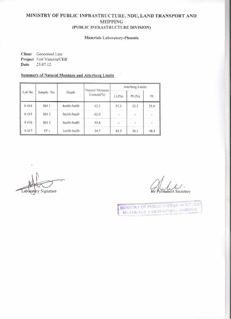
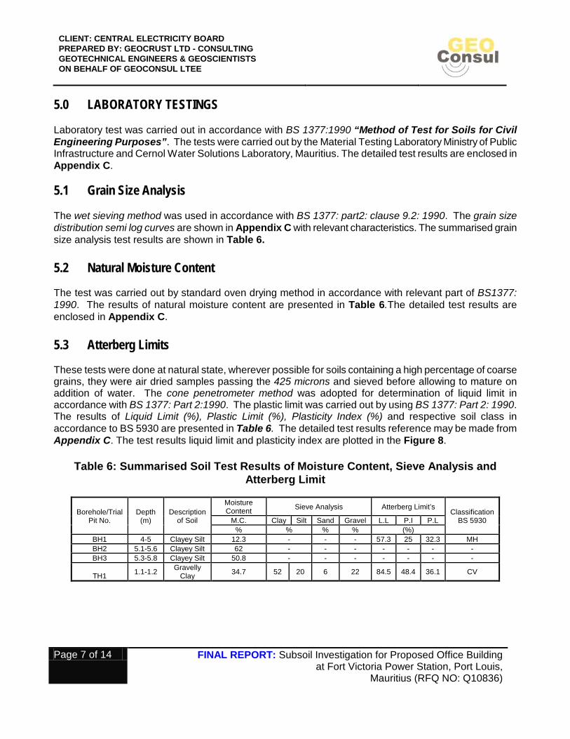
5.0 LABORATORY TESTINGS Laboratory test was carried out in accordance with BS 1377:1990 “Method of Test for Soils for Civil Engineering Purposes”. The tests were carried out by the Material Testing Laboratory Ministry of Public Infrastructure and Cernol Water Solutions Laboratory, Mauritius. The detailed test results are enclosed in Appendix C. 5.1 Grain Size Analysis The wet sieving method was used in accordance with BS 1377: part2: clause 9.2: 1990. The grain size distribution semi log curves are shown in Appendix C with relevant characteristics. The summarised grain size analysis test results are shown in Table 6. 5.2 Natural Moisture Content The test was carried out by standard oven drying method in accordance with relevant part of BS1377: 1990. The results of natural moisture content are presented in Table 6.The detailed test results are enclosed in Appendix C. 5.3 Atterberg Limits These tests were done at natural state, wherever possible for soils containing a high percentage of coarse grains, they were air dried samples passing the 425 microns and sieved before allowing to mature on addition of water. The cone penetrometer method was adopted for determination of liquid limit in accordance with BS 1377: Part 2:1990. The plastic limit was carried out by using BS 1377: Part 2: 1990. The results of Liquid Limit (%), Plastic Limit (%), Plasticity Index (%) and respective soil class in accordance to BS 5930 are presented in Table 6. The detailed test results reference may be made from Appendix C. The test results liquid limit and plasticity index are plotted in the Figure 8.
Table 6: Summarised Soil Test Results of Moisture Content, Sieve Analysis and
Atterberg Limit
Borehole/Trial Pit No.
Depth (m)
Description of Soil
Moisture Content Sieve Analysis Atterberg Limit’s
Classification BS 5930 M.C. Clay Silt Sand Gravel L.L P.I P.L
% % % % (%) BH1 4-5 Clayey Silt 12.3 - - - 57.3 25 32.3 MH BH2 5.1-5.6 Clayey Silt 62 - - - - - - - BH3 5.3-5.8 Clayey Silt 50.8 - - - - - - -
TH1 1.1-1.2 Gravelly Clay 34.7 52 20 6 22 84.5 48.4 36.1 CV

CLIENT: CENTRAL ELECTRICITY BOARD PREPARED BY: GEOCRUST LTD - CONSULTING GEOTECHNICAL ENGINEERS & GEOSCIENTISTS ON BEHALF OF GEOCONSUL LTEE
Page 8 of 14 FINAL REPORT: Subsoil Investigation for Proposed Office Building at Fort Victoria Power Station, Port Louis,
Mauritius (RFQ NO: Q10836)
5.4 Proctor Compaction and CBR Tests
The CBR tests were performed in accordance to BS1377: part4: clause 7.2.4.2 using 4.5 kg rammer. The period of soaking was 4 days. The relationship between maximum dry density and optimum moisture content with CBR Values for different blows are presented in Table 7.The detailed laboratory test results reference may be made from Appendix C.
Table 7: Results of Proctor and Soaked California Bearing Ratio (CBR) Test
Sample Location
Proctor CBR (Soaked) Rammer Method
Max. Dry
Density
Optimum Moisture Content
No. of Blows
Dry Density
Swelling Moisture Content
C.B.R Values (%) at
Depth(m) g/cm3 % g/cm3 % % 2.5 mm
5.0 mm
TP1 (1.1-1.2m)
CBR (4 Days Soaking) 4.5kg 1.601 25 15 1.521 4.98 40 1.4 1.6
31 1.518 3.98 38.6 1.8 1.9 62 1.642 4.11 37.4 2.4 2.2
5.5 Chemical Analysis of Groundwater Sample The chemical analysis groundwater sample from BH2 for determination of pH, sulphate and chloride content was carried out by Cernol Water Solutions Ltd. The standard used for the testing is unknown. The detailed test results are presented in Appendix C.

CLIENT: CENTRAL ELECTRICITY BOARD PREPARED BY: GEOCRUST LTD - CONSULTING GEOTECHNICAL ENGINEERS & GEOSCIENTISTS ON BEHALF OF GEOCONSUL LTEE
Page 9 of 14 FINAL REPORT: Subsoil Investigation for Proposed Office Building at Fort Victoria Power Station, Port Louis,
Mauritius (RFQ NO: Q10836)
6.0 GUIDELINE FOR DESIGN CONSIDERATIONS AND DISCUSSIONS
The following recommendations are based on the information available on the proposed office building developments (structures), observations made at the subject site, interpretation of the data obtained from the subsurface investigations, and our experience with similar soils and subsurface conditions. Since the soil test drillings represent a very small statistical sampling of the subsurface conditions, subsurface conditions could vary substantially from those indicated by the soil test drillings. In such instances, adjustments to the design and construction of the proposed structures might be necessary, depending on the conditions encountered.
6.1 Foundation Design Consideration On basis of the engineering properties of subsoil and sub-surface conditions, a Strip/Pad/Spread footing would be appropriate for low to medium range of loads for proposed development.
The minimum depth at which a foundation should be placed depends on the soil profile, structural requirement, and ground water condition. The following factors should generally be taken into consideration in determining the depth of foundations.
• Depth of top soil, rubbish or uncontrolled fills or suspicious material if any. • Depth of poor surface deposit such as peat, muck, or sanitary land fills. • Location of ground water table and its seasonal fluctuation • Depth of poor or better underlying strata. • Depth of adjacent footings, as applicable
If the subsoil near the ground surface consists of a heterogenous fill of uncertain properties or compressible soil like peat, muck etc. the foundation should preferably be taken below the fill to a native dense undisturbed strata/dense undisturbed engineered fill (compacted/consolidated earth)/strong rock. The structure should be designed to resist stresses imposed by irregular displacements, the prediction of differential settlement is often hazardous and it may be preferable to endeavor to reduce differential settlement or to attain sensibly uniform settlement of all parts of the structure. The following methods can be employed to reduce differential settlement.
1. Adjust of design load on foundation: not often practicable. 2. Adjustment of proportions or depths of individual foundations: generally effected by trial and
error; 3. Transfer of load to deeper, less compressible strata by piers or piles 4. Provision of rigid raft foundation: the raft must be sufficiently strong to resist stresses imposed
by non-uniform distribution of bearing stress. 5. Excavating highly compressible strata below design grade of foundation and replacing it with
well compacted granular materials

CLIENT: CENTRAL ELECTRICITY BOARD PREPARED BY: GEOCRUST LTD - CONSULTING GEOTECHNICAL ENGINEERS & GEOSCIENTISTS ON BEHALF OF GEOCONSUL LTEE
Page 10 of 14 FINAL REPORT: Subsoil Investigation for Proposed Office Building at Fort Victoria Power Station, Port Louis,
Mauritius (RFQ NO: Q10836)
6.2 Foundation Type (Strip/Pad/ Spread Footing), Depth & Allowable Bearing Capacity of Soil/Broken Rock On basis of soil characteristics encountered at this site, conventional shallow strip and/or pad foundation system can be adopted for proposed new office building. The following bearing capacity was calculated based on preliminary available SPT value of soil as well bed rock data, ideal subsurface profile, engineering parameters of each soil/rock types and assumption based on our professional judgments on similar type of soil:
It is recommended that the foundation should be placed at minimum depth of 1.5m in the native dense/stiff undisturbed residual soil or undisturbed weathered rock which ever depth is reached first. The maximum allowable bearing capacity of 150kpa (at 1.5-2.5m below existing ground level) may be used for the design of footings within native residual soil (the native undisturbed stiff / dense residual soil/ within dense undisturbed engineered fill). Settlement of these strip / strip footings should be less than 25mm or that to be tolerable for this type of structure. The above figures are conservatively based on a factor of safety 3 with usual settlement tolerances. Actual settlements are expected to be minimal with thorough hand cleaning and compaction of founding surfaces. If such foundation system is not found to be acceptable, the raft foundation can be adopted.
For fragmented/broken/highly to completely weathered rock below 1.5-2.5m below ground level, the guidelines of the British Standard Code of Practice for Foundations (BS 8004: 1986) has been used to estimate the allowable bearing capacity. The allowable bearing capacity of 300 kPa (at least) with a factor of safety of 3 should be used. The following parameters were assumed for analysis
qc = unconfined compressive strength of rock = 5 MPa (poor condition)
S = permitted settlement = 25 mm, B = width of the footing = 1.5 m (assumed), j = mass factor of the rock = 0.1 (for an RQD<25%), Mr = modulus ratio = 300 (for local basalt), I = influence factor = 0.95 for a square pad footing.
It is important that all bearing surfaces of foundation must be inspected and approved by our geotechnical engineer prior to pouring concrete to confirm soil conditions/origin of soil and bearing pressures as anticipated in design. Any existing disturbed native soil/ low bearing soil (loose/ soft)/ uncontrolled fill / loose to disturbed boulders should be removed, and replaced with lean concrete (Non-shrink) or crushed clean granular or granular fill prior to pour concrete. If residual soil has high swelling and shrinkage potential (high plasticity clay) so that foundation must be placed below the zone of moisture content fluctuations strata. Alternatively, Mitigation measures may include removal and replacement of the expansive soil from the bottom of foundation with non expansive materials. The extreme caution should be taken during construction to ensure that all footings bear in engineered fill or native undisturbed stiff low plasticity silty clay. It is recommended that under no conditions the footing should be placed on old uncontrolled fill since the consolidation characteristics can not be predicted and unacceptable settlements of footings may result. Loose or disturbed materials should be removed from the footing excavation prior to placement of concrete. Hand cleaning may be required to prepare an acceptable bearing surface. The foundation sub-grade excavation should be protected from the ingress of free water, resulting in the softening of the soil. The footing must not be placed on fill, organic, disturbed soil. Bearing soil that becomes frozen, loose, or softened must be removed and replaced with concrete, or the foundation
CLIENT: CENTRAL ELECTRICITY BOARD PREPARED BY: GEOCRUST LTD - CONSULTING GEOTECHNICAL ENGINEERS & GEOSCIENTISTS ON BEHALF OF GEOCONSUL LTEE
Page 11 of 14 FINAL REPORT: Subsoil Investigation for Proposed Office Building at Fort Victoria Power Station, Port Louis,
Mauritius (RFQ NO: Q10836)
sub-grade should be extended to reach soil in an unaffected condition. 6.3 SITE PREPARATION & GRADING Final site grades had not been established at the time of investigation. However, it is anticipated that some grading (cut and fill operation) will be carried out at the site. Site preparation will include the removal of all top soil/fill (non-engineered) and unsuitable material (such as wet/ soft/organics soils/high plasticity soil etc.) under building foundation / development areas / roadways. The exposed sub-grade surface should be proof rolled with a heavy loaded truck and examined by geotechnical personnel. Any soft areas detected during proof rolling process should be sub-excavated. The area can then be brought up to the final sub-grade level with approved on-site or imported material placed in lifts not exceeding 200m and compacted to the following requirements:
• Within building area (for slab on grade support): minimum of 98% standard proctor maximum dry density. • Pavement areas: minimum of 98 % of standard proctor maximum dry density. • Engineered fill for foundation support (if required): 100% standard proctor maximum dry density. 6.4 EXCAVATIONS AND GROUNDWATER CONTROL Normal excavation practice is applicable at this site, namely vertical cut for 1.2m and 45 degree side slopes for deeper trench for stability purposes. In general groundwater may be expected to be a construction factor if excavation will be made below 3.9m from existing ground level. In all cases, the excavation must comply with the Occupational Health and Safety Regulations Act of the Jurisdiction or local standard code of practices. 6.5 SURFACE DRAINAGE As a primary drainage measure, surface grading of the proposed development should be provided in order to drain away from the structure and prevent surficial erosion and infiltration into the foundation soil. A minimum 2-3% slope should be provided for a distance of 3.0m (minimum) from the structure. In general, water should not be allowed to accumulate next to the foundation. The upper 0.6m of the backfill around the structure should consist of compacted non expansive clay should be placed to act as seal against the ingress of surface runoff water. 6.6 Pavement Structure Design It is understood that the proposed development will consist of the pavement structure is required for light to medium duty traffic. In principle, the fundamental criteria for pavement base support is that of dense unyielding sub-grade which is free of any weakness, rutting or visible flexing as verified by a normal proof rolling test using a fully loaded dump truck or equivalent. The upper 300mm of native sub-grade should be scarified and re-compacted to at least 98% of Standard Proctor Maximum Dry Density. Any soft or flexing or uncontrolled fill areas thus revealed may be rectified as required prior to granular placement. Soft, wet and/or flexing areas may require sub-excavations and replacement with additional base gravel and possibly geotextile fabric. The sub-excavated areas must maintain positive sub-grade drainage to catch basins or manholes complete with wrapped weep hole, to limit areas where water is allowed to pond. In areas of shallow ground water within or directly below the pavement structure these weeper drain systems will be required.

CLIENT: CENTRAL ELECTRICITY BOARD PREPARED BY: GEOCRUST LTD - CONSULTING GEOTECHNICAL ENGINEERS & GEOSCIENTISTS ON BEHALF OF GEOCONSUL LTEE
Page 12 of 14 FINAL REPORT: Subsoil Investigation for Proposed Office Building at Fort Victoria Power Station, Port Louis,
Mauritius (RFQ NO: Q10836)
The majority of the asphalt covered areas will consist of pavement for access road and parking areas around the building. Based on our local experience in similar type of on-site clayey silt /gravelly clay sub-grade soil and laboratory test results, we recommend that CBR (California Bearing Ratio) rating of 2 should be used in the design of the pavement structures at this site. The design engineer will determine, on a case by case basis, the minimum pavement structure required for higher Functional Classifications. We recommend the following pavement structure should be design in accordance with AASTHO guideline minimum requirements for the pavement. The following precautions shall be taken during construction:
• The subsoil conditions/bearing surface should be verified by qualified geotechnical engineer at founding level to confirm bearing pressures as well as origin and strength of soil at founding level of the footing. Any existing disturbed native soil/low bearing soil (loose/soft)/uncontrolled fill should be removed, and replaced with lean concrete or crushed clean granular or granular fill prior to pour concrete. If expansive clay encountered at the base of footing, Mitigation measures may include removal and replacement of the expansive soil from the bottom of foundation with non expansive acceptable fill material.
• Adequate drainage system shall be provided to eliminate surface water infiltration around the
building foundation.
• Adequate remedial measure shall be provided during excavation close to existing structure in order to avoid undermining foundation sub-grade of existing structure.
Other design considerations: The site conditions preclude any risk of ground heave or ground sliding. There are no visible signs of slope instabilities in the vicinity of the site. It must be noted that the above should be considered as a guideline and the required analysis should be carried out by design engineer.

CLIENT: CENTRAL ELECTRICITY BOARD PREPARED BY: GEOCRUST LTD - CONSULTING GEOTECHNICAL ENGINEERS & GEOSCIENTISTS ON BEHALF OF GEOCONSUL LTEE
Page 13 of 14 FINAL REPORT: Subsoil Investigation for Proposed Office Building at Fort Victoria Power Station, Port Louis,
Mauritius (RFQ NO: Q10836)
7.0 CONCLUSIONS
For the purpose of foundation design, the subsoil ground profile is presented on the basis of the stringent case as follows (From Existing Ground Level to Bottom of Test Holes/Trial Pit):
0.0-1.50m: Uncontrolled fill-Loose to Medium Dense or firm to stiff consistency; 1.50-2.50m: Strong, greyish to brown, vesicular BASALT BOULDERS, highly weathered (HW) in matrix of clayey silt, Clayey Silt Material shows in-situ pocket penetrometer reading 1.5kg/cm2; 2.50-12.00m: Very weak to weak and occasional moderately strong, grey to purple AGGLOMERATE PLUS BASALT / moderately strong to strong BASALT ROCK, moderately to completely weathered; and 12.00-15.00m (maximum Investigated Depth): Moderately strong to strong, grey to purple, vesicular to non-vesicular BASALT ROCK, highly weathered (HW), RQD=10-26%
On basis of our field investigations findings, the construction of the proposed
development site is feasible from a geotechnical standpoint. Based on the subsurface conditions encountered, a shallow foundation system (strip/pad footing) shall be used to support the proposed structure. It is recommended to place foundations at a minimum depth of 1.5m in the dense/stiff undisturbed residual soil or on weathered rock whichever depth reached first.
It is recommended that the foundation should be placed at minimum depth of 1.5m in
the native dense/stiff undisturbed residual soil or undisturbed weathered rock which ever depth is reached first. The maximum allowable bearing capacity of 150kpa (at 1.5-2.5m below existing ground level) may be used for the design of footings within native residual soil (the native undisturbed stiff / dense residual soil/ within dense undisturbed engineered fill). If expansive/shrinkage/moisture fluctuating residual soil encountered at the base of footing, Mitigation measures may include removal and replacement of the expansive soil from the bottom of foundation with non expansive materials.
For fragmented/broken/highly to completely weathered rock below 1.5-2.5m
below ground level, the guidelines of the British Standard Code of Practice for Foundations (BS 8004: 1986) has been used to estimate the allowable bearing capacity. The allowable bearing capacity of 300 kPa (at least) with a factor of safety of 3 should be used.
Groundwater conditions were encountered at BH-2 and BH-3 varies from 3.9-4.0m
below existing ground levels after two weeks of drilling.
Based on our local experience in similar type of on-site clayey silt /gravelly clay sub-grade soil and laboratory test results, we recommend that CBR (California Bearing Ratio) rating of 2 should be used in the design of the pavement structures at this site. The design engineer will determine, on a case by case basis, the minimum pavement structure required for higher Functional Classifications.

CLIENT: CENTRAL ELECTRICITY BOARD PREPARED BY: GEOCRUST LTD - CONSULTING GEOTECHNICAL ENGINEERS & GEOSCIENTISTS ON BEHALF OF GEOCONSUL LTEE
Page 14 of 14 FINAL REPORT: Subsoil Investigation for Proposed Office Building at Fort Victoria Power Station, Port Louis,
Mauritius (RFQ NO: Q10836)
8.0 REFERENCES British Standard Institution (1999): Code of Practice for Site Investigation: BS 5930, British Standard Institution, London. British Standard Institution (1990): Methods of Test for Soil for Civil Engineering Purposes: BS 1377, British Standard Institution, London. Quarterly Journal of Engineering Geology (1995): The Working Party Report the description and classification of weathered rocks for engineering purposes Geological Society Engineering Group, Vol. 28, P 207-242. Geological Society of London. Giorgi, Loicc (1999): Carte Geologiue au 1:50000 Schema hydrogeologique, Mauritius. Parish, D.H. (1965): Notes on the1:100000 Soil Map of Mauritius. Published by MSRI, Mauritius
9.0 CLOSURE This final report has been prepared for the exclusive use of CENTRAL ELECTRICITY BOARD and their representatives for specific application to the area described within this report. The material contained in the report reflects our best judgment of GEOCRUST LTD., in the light of the information available at the time of the preparation. We trust that this report is self explanatory. We appreciate the opportunity of providing this service for you. If you have any questions concerning this report, please do not hesitate to contact this office. Respectfully Submitted, GEOCONSUL LTEE Prepared by Mr. Karthikeyan Ganesan, M.Tech. Engineering Geologist GEOCRUST LTD.
Reviewed by Chandra Acharya, M.ASc., M.Tech., P.Eng., RPEM Senior Geotechnical Engineering Specialist Registered Professional Engineer of Mauritius (ID. 1202) Professional Engineer of Canada (ON, AB, BC, SK) July 24, 2012 Enclosures: Appendix A to C

Appendix A
Subsoil Investigation at Fort Victoria, Port Louis, Mauritius (RFQ NO: Q10836)
Figures: Location of project site-Vicinity Map; Land use Map; Geological Map; Soil Map of Project Site; Borehole Drilling and Trial pit Location;
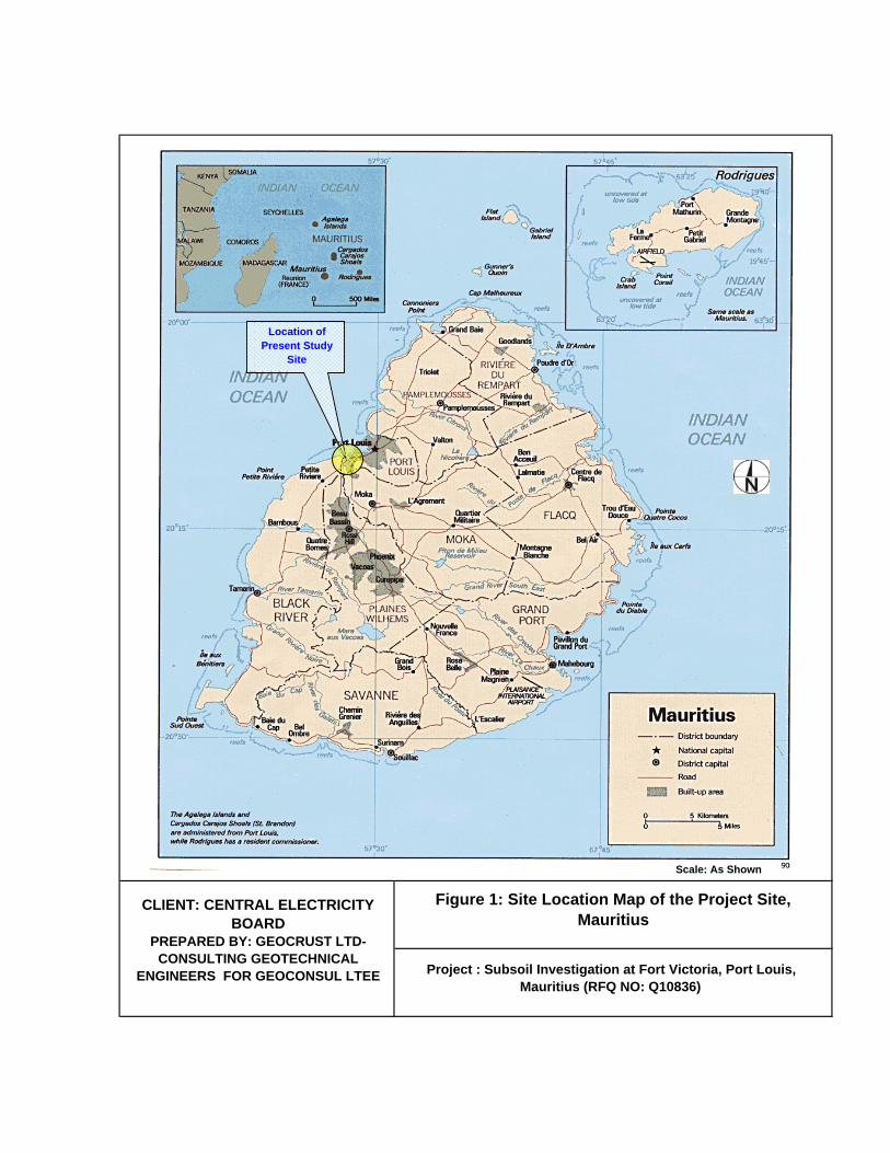
Figure 1: Site Location Map of the Project Site, Mauritius
Project : Subsoil Investigation at Fort Victoria, Port Louis, Mauritius (RFQ NO: Q10836)
Scale: As Shown
Location of Present Study
Site
CLIENT: CENTRAL ELECTRICITY BOARD
PREPARED BY: GEOCRUST LTD-CONSULTING GEOTECHNICAL
ENGINEERS FOR GEOCONSUL LTEE

Figure 2 : Landuse Map of the Project Site
Project : Subsoil Investigation at Fort Victoria, Port Louis, Mauritius (RFQ NO: Q10836)
CLIENT: CENTRAL ELECTRICITY BOARDPREPARED BY: GEOCRUST LTD-CONSULTING
GEOTECHNICAL ENGINEERS FOR GEOCONSUL LTEE
Location of Present Study Site for future
development

Figure 3: Regional Geological map of Project Site
(Not to the scale – scanned from Carte Geologiue au 1:50000 scheme
hydrogeologiue, Mauritius.Giorgi Loicc 1999)
Project : Subsoil Investigation at Fort Victoria, Port Louis, Mauritius (RFQ NO: Q10836)
Approximate Location of ProjectSite - Intermediate Volcanic Formation
CLIENT: CENTRAL ELECTRICITY BOARD
PREPARED BY: GEOCRUST LTD-CONSULTING GEOTECHNICAL
ENGINEERS FOR GEOCONSUL LTEE
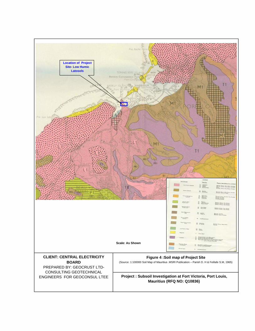
Figure 4 :Soil map of Project Site (Source: 1:100000 Soil Map of Mauritius .MSRI Publication – Parish D. H & Feillafe S.M, 1965)
Scale: As Shown
Project : Subsoil Investigation at Fort Victoria, Port Louis, Mauritius (RFQ NO: Q10836)
Location of Project Site- Low Humic
Latosols
CLIENT: CENTRAL ELECTRICITY BOARD
PREPARED BY: GEOCRUST LTD-CONSULTING GEOTECHNICAL
ENGINEERS FOR GEOCONSUL LTEE

Figure 5: Approximate Location of Rotary Corehole Drilling & Trial Pit Exploration at Proposed Development
Site - Aerial view of the Project Site (Reference Google Digital Globe)
Project : Subsoil Investigation at Fort Victoria, Port Louis, Mauritius (RFQ NO: Q10836)
CLIENT: CENTRAL ELECTRICITY BOARDPREPARED BY: GEOCRUST LTD-
CONSULTING GEOTECHNICAL ENGINEERS FOR GEOCONSUL LTEE
Location of Present Study Site
BH1
BH3BH2
TP1
Legend:Approximate Location of Rotary Corehole Drilling SiteTrial Pit Location

Appendix B
Legends , Terms and Symbols used in accordance With BS5930-1999; Geotechnical Log of Borehole and Core Photographs; Geotechnical Log of Trial pit and Trial Pit Photographs;
Subsoil Investigation at Fort Victoria, Port Louis, Mauritius (RFQ NO: Q10836)

LEGENDS FOR SYMBOLIC LOG Silt x x x
x x x Basalt (Strong,
Slight Weathered) VVV VVV
Clay - - -
- - - Moderately Weak to
moderately strong (MW-MS) , BASALT, moderately to highly weathered (MW-HW),
vvv vvv
Sand ……. ……..
Moderately weak to moderately strong (MW-MS) BASALT PLUS PYROCLASTIC material. moderately to highly weathered (MW-HW),
v++v v++v
Gravel 0 0 0 0000
Very Weak to weak (VW-W), BASALT PLUS AGGLOMERATE mixture, completely weathered (CW) to residual grade
v++v OOO
Silty Gravel X0x0 X0x0
Clayey Silt x-x-x x-x-x
Top Soil
Water Level
Uncontrolled Fill
NI Non-Intact
SPT(N) Standard Penetration Test(SPLIT SPOON)
SPT(SC) Standard Penetration Test(SOLID CONE)


Logged By & Reviewed By: GK & CA Collar Coordinates: Not AvailableDate of Logged: May 10, 2012 Collar Elevation (m): Not AvailableDate of Photograph: May 10, 2012 Drilling Rig: APAFOR 560 Drilled By: FO
Location: Fort Victoria Power Station, Port Louis Drilling Started: May 09, 2012 Dia. Of Hole: 88.9mmDrilling Method:Rotary Diamond Core using NMLC Drilling Completed: May 9, 2012 Depth: 14.80m
Cas
ing
Siz
e an
d P
rogr
ess
Dep
th (m
)
Dril
ling
Run
& F
luid
use
d fo
r dril
ling
Pen
etra
tion
Tim
e (m
in)
Per
Run
Tota
l Cor
e R
ecov
ery
TCR
(%
)
Sol
id C
ore
Rec
over
y S
CR
(%
)R
ock
Qua
lity
Des
igna
tion
(R.Q
.D %
)
In-s
itu T
est
(SP
T/P
erm
eabi
lity
Test
)
Sam
ples
for L
abor
ator
y Te
st
Frac
ture
Fre
quen
cy p
er m
STRATA DESCRIPTIONS (Soil / Rock)
Elev
atio
n (m
) fro
m
Gou
nd L
evel
(GL)
Sym
bolic
Log
Stan
dpip
e Pi
ezom
eter
(if
any)
0.0 EXISTING GROUND LEVEL 0.0 0.1 0.1 xoxox0.2 0.2 xoxox0.3 0.3 xoxox0.4 0.4 xoxox0.5 0.5 xoxox0.6 0.6 xoxox0.7 0.7 xoxox0.8 0.8 xoxox0.9 0.9 xoxox1.0 NI 1.0 xoxox1.1 1.1 xoxox1.2 1.2 X-X-X1.3 1.3 X-X-X1.4 1.4 X---X1.5 D 80 4 0 SPT-1 1.5 vvv1.6 RF 1.6 vvv1.7 1.7 vvv1.8 1.8 vvv1.9 1.9 vvv2.0 NI 2.0 vvv2.1 2.1 vvv2.2 2.2 vvv2.3 2.3 vvv2.4 2.4 vvv2.5 2.5 vvv2.6 2.6 vvv2.7 2.7 vvv2.8 2.8 vvv2.9 2.9 vvv3.0 W 80 38 0 NI 3.0 vvv3.1 3.1 vvv3.2 3.2 vvv3.3 3.3 vvv3.4 3.4 vvv3.5 3.5 vvv3.6 3.6 vvv3.7 3.7 vvv3.8 3.8 vvv3.9 3.9 vvv4.0 W 80 52 0 NI 4.0 v+v4.1 SPT-2 N 4.15 v+v4.2 4.2 v+v4.3 4.3 v+v4.4 4.4 v+v4.5 10 4.5 v+v4.6 4.6 v+v4.7 4.7 v+v4.8 4.8 ooo4.9 4.9 v+v5.0 NI 5.0 v+v5.1 5.1 v+v5.2 5.2 v+v5.3 5.3 v+v5.4 5.4 v+v5.5 D 80 0 0 5.5 v+v5.6 5.6 vvv5.7 5.7 vvv5.8 5.8 vvv5.9 5.9 vvv6.0 NI 6.0 vvv6.1 6.1 vvv6.2 6.2 vvv6.3 6.3 vvv6.4 6.4 vvv6.5 6.5 vvv
(Continued in Next Page)
Dow
nhol
e D
rillin
g D
epth
(m
)
Cha
nge
of S
trat
a (m
) fr
om E
xist
ing
GL
Sheet: 1 OF 3
CLIENT: CENTRAL ELECTRICITY BOARD
Consulting Geotechnical Engineers & Geoscientists
Subsoil Investigation at Fort Victoria, Port Louis, Mauritius (RFQ NO: Q10836)
COREHOLE LOGGING: BH-1
Geotechnical Drilling Contractor
Prepared By
BH-1Sheet: 1 / 3
3.90-5.40mVery weak to weak (VW-W)/medium dense, light to dark brown with occassional discolouration, fine to medium grained AGGLOMERATE PLUS BASALT mixture in form of clayey silt gravel cobble form, completely weathered (CW), fracture characteristics unable identify due to weathered condition, some parts crushed in drilling in form of gravel cobble form.
1.10 - 1.41mStiff, light brown colour with black stained CLAYEY SILT
0.0-1.10mFirm, dark greyish brown GRAVELLY SILT with plant roots (FILL)
1.41-3.90mModerately strong to strong (MS-S) with occassional weak layers (W), light grey to light purple with yellowish discolurations, fine to medium grained, vesicular BASALT BOULDERS, highly weathered (HW).
5.40-7.34mModerately strong to strong (MS-S) with occassional weak layers (W), light grey to purple with yellowish discolurations, fine to medium grained, mostly vesicular BASALT, highly weathered (HW), 2 sets of joint, dipping @10-30 & 60-90 degree, close to medium joint spacing, joint surface planar to rough.

Cas
ing
Siz
e an
d P
rogr
ess
Dep
th (m
)
Dril
ling
Run
& F
luid
use
d fo
r dril
ling
Pen
etra
tion
Tim
e (m
in) P
er
Run
Tota
l Cor
e R
ecov
ery
TCR
(%
)
Sol
id C
ore
Rec
over
y S
CR
(%
)R
ock
Qua
lity
Des
igna
tion
(R.Q
.D %
)
In-s
itu T
est
(SP
T/P
erm
eabi
lity
Test
)
Sam
ples
for L
abor
ator
y Te
st
Frac
ture
Fre
quen
cy p
er m
STRATA DESCRIPTIONS (Soil / Rock)
Elev
atio
n (m
) fro
m G
ound
Le
vel (
GL)
Sym
bolic
Log
Stan
dpip
e Pi
ezom
eter
(if
any)
6.5 CONTINUED FROM PREVIOUS PAGE 6.56.6 6.6 vvv6.7 6.7 vvv6.8 6.8 vvv6.9 6.9 vvv7.0 W 90 49 38 NI 7.0 vvv7.1 7.1 vvv7.2 7.2 vvv7.3 7.3 vvv7.4 7.4 vvv7.5 7.5 v+v7.6 7.6 ooo7.7 7.7 v+v7.8 7.8 v+v7.9 7.9 ooo8.0 W 75 17 0 NI 8.0 v+v8.1 SPT-3 N 8.1 ooo8.2 8.2 v+v8.3 8.3 v+v8.4 8.4 ooo8.5 23 8.5 v+v8.6 8.6 v+v8.7 8.7 ooo8.8 8.8 v+v8.9 8.9 v+v9.0 >10 9.0 ooo9.1 9.1 v+v9.2 9.2 ooo9.3 9.3 v+v9.4 9.4 v+v9.5 W 80 5 0 9.5 ooo9.6 9.6 v+v9.7 9.7 v+v9.8 9.8 ooo9.9 9.9 v+v
10.0 >10 10.0 v+v10.1 10.1 ooo10.2 10.2 v+v10.3 10.3 ooo10.4 10.4 v+v10.5 W 90 0 0 10.5 v+v10.6 10.6 ooo10.7 10.7 v+v10.8 10.8 v+v10.9 10.9 ooo11.0 NI 11.0 v+v11.1 11.1 v+v11.2 11.2 ooo11.3 11.3 v+v11.4 11.4 ooo11.5 W 80 23 0 11.5 vvv11.6 11.6 vvv11.7 11.7 vvv11.8 11.8 vvv11.9 11.9 vvv12.0 >10 12.0 vvv12.1 12.1 vvv12.2 12.2 vvv12.3 12.3 vvv12.4 12.4 vvv12.5 12.5 vvv12.6 12.6 vvv12.7 12.7 vvv12.8 12.8 vvv12.9 12.9 vvv13.0 W 70 27 0 NI 13.0 vvv13.1 13.1 vvv13.2 13.2 vvv13.3 13.3 vvv13.4 13.4 vvv13.5 13.5 vvv13.6 13.6 vvv13.7 13.7 vvv13.8 13.8 vvv13.9 13.9 vvv14.0 W 70 22 0 NI 14.0 vvv
(Continued in Next Page)
Sheet: 2 / 3BH-1
COREHOLE LOGGING: BH-1D
ownh
ole
Dril
ling
Dep
th
(m)
Cha
nge
of S
trat
a (m
) fr
om E
xist
ing
GL
Consulting Geotechnical Engineers & Geoscientists
Subsoil Investigation at Fort Victoria, Port Louis, Mauritius (RFQ NO: Q10836)Geotechnical Drilling
Contractor
Prepared By CLIENT: CENTRAL ELECTRICITY BOARD
7.34-11.40mVery weak to moderately weak (VW-MW)/medium dense to dense, light brown to dark grey with occassional discolouration, fine to medium grained AGGLOMERATE PLUS BASALT mixture in form of clayey silt gravel cobble form, completely weathered (CW), fracture characteristics unable identify due to completely weathered condition, some parts crushed in drilling in form of gravel cobble form.
11.40-14.80mModerately strong to moderately weak (MS-MW) with alternate weak to very weak layers (W), light grey to light purple with yellowish discolurations and brownish stained, fine to medium grained, mostly vesicular BASALT, highly weathered (HW), 1 set of joint, dipping @60-90 degree, medium joint spacing, joint surface planar to rough.
Cas
ing
Siz
e an
d P
rogr
ess
Dep
th (m
)
Dril
ling
Run
& F
luid
use
d fo
r dril
ling
Pen
etra
tion
Tim
e (m
in) P
er
Run
Tota
l Cor
e R
ecov
ery
TCR
(%
)
Sol
id C
ore
Rec
over
y S
CR
(%
)R
ock
Qua
lity
Des
igna
tion
(R.Q
.D %
)
In-s
itu T
est
(SP
T/P
erm
eabi
lity
Test
)
Sam
ples
for L
abor
ator
y Te
st
Frac
ture
Fre
quen
cy p
er m
STRATA DESCRIPTIONS (Soil / Rock)
Elev
atio
n (m
) fro
m G
ound
Le
vel (
GL)
Sym
bolic
Log
Stan
dpip
e Pi
ezom
eter
(if
any)
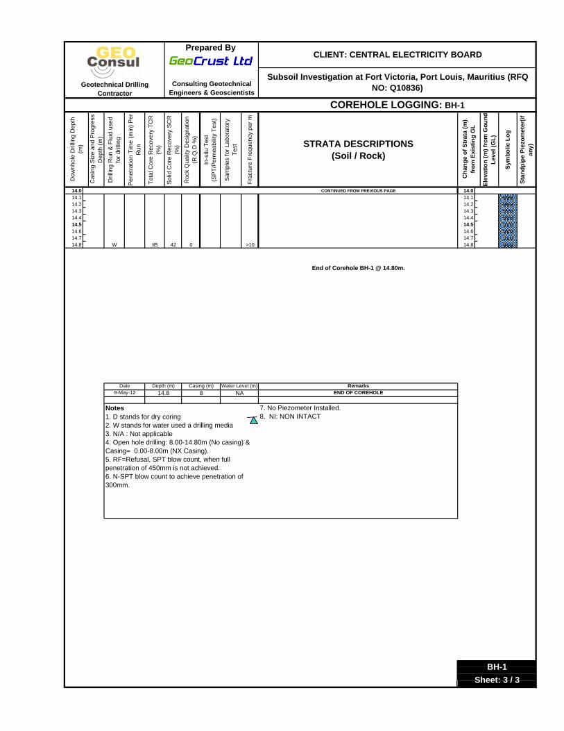
14.0 CONTINUED FROM PREVIOUS PAGE 14.014.1 14.1 vvv14.2 14.2 vvv14.3 14.3 vvv14.4 14.4 vvv14.5 14.5 vvv14.6 14.6 vvv14.7 14.7 vvv14.8 W 85 42 0 >10 14.8 vvv
RemarksEND OF COREHOLE
7. No Piezometer Installed. 8. NI: NON INTACT
BH-1Sheet: 3 / 3
Notes 1. D stands for dry coring 2. W stands for water used a drilling media3. N/A : Not applicable4. Open hole drilling: 8.00-14.80m (No casing) & Casing= 0.00-8.00m (NX Casing). 5. RF=Refusal, SPT blow count, when full penetration of 450mm is not achieved. 6. N-SPT blow count to achieve penetration of 300mm.
Date Depth (m) Casing (m) Water Level (m)9-May-12 14.8 8 NA
COREHOLE LOGGING: BH-1
End of Corehole BH-1 @ 14.80m.
Geotechnical Drilling Contractor
Prepared By CLIENT: CENTRAL ELECTRICITY BOARD
Consulting Geotechnical Engineers & Geoscientists
Subsoil Investigation at Fort Victoria, Port Louis, Mauritius (RFQ NO: Q10836)
Cha
nge
of S
trat
a (m
) fr
om E
xist
ing
GL
Dow
nhol
e D
rillin
g D
epth
(m
)

CLIENT: CENTRAL ELECTRICITY BOARD PREPARED BY: GEOCRUST LTD -CONSULTING GEOTECHNICAL ENGINEERS & GEOSCIENTISTS ON BEHALF OF GEOCONSUL LTEE
Subsoil Investigation for Proposed Office Building at Fort Victoria Power Station, Port Louis, Mauritius
COREHOLE (BH-1) Depth : 0.00 – 9.00m
CENTRAL ELECTRICITY BOARD
CENTRAL ELECTRICITY BOARD
CENTRAL ELECTRICITY BOARD
(Continued…)
COREPHOTOGRAPHSBH1/Page 1 of 2

CLIENT: CENTRAL ELECTRICITY BOARD PREPARED BY: GEOCRUST LTD -CONSULTING GEOTECHNICAL ENGINEERS & GEOSCIENTISTS ON BEHALF OF GEOCONSUL LTEE
Subsoil Investigation for Proposed Office Building at Fort Victoria Power Station, Port Louis, Mauritius
COREHOLE (BH1)
Depth :9.00 –14.80m
CENTRAL ELECTRICITY BOARD
END OF CORE HOLE BH1 @ 14.80M
CENTRAL ELECTRICITY BOARD
COREPHOTOGRAPHSBH1/Page 2 of 2

Logged By & Reviewed By: GK & CA Collar Coordinates: Not AvailableDate of Logged: May 11, 2012 Collar Elevation (m): Not AvailableDate of Photograph: May 11, 2012 Drilling Rig: APAFOR 560 Drilled By: JL
Location: Fort Victoria Power Station, Port Louis Drilling Started: May 10, 2012 Dia. Of Hole: 88.9mmDrilling Method:Rotary Diamond Core using NMLC Drilling Completed: May 10, 2012 Depth: 15.00m
Cas
ing
Siz
e an
d P
rogr
ess
Dep
th (m
)
Dril
ling
Run
& F
luid
use
d fo
r dril
ling
Pen
etra
tion
Tim
e (m
in)
Per
Run
Tota
l Cor
e R
ecov
ery
TCR
(%
)
Sol
id C
ore
Rec
over
y S
CR
(%
)R
ock
Qua
lity
Des
igna
tion
(R.Q
.D %
)
In-s
itu T
est
(SP
T/P
erm
eabi
lity
Test
)
Sam
ples
for L
abor
ator
y Te
st
Frac
ture
Fre
quen
cy p
er m
STRATA DESCRIPTIONS (Soil / Rock)
Elev
atio
n (m
) fro
m
Gou
nd L
evel
(GL)
Sym
bolic
Log
Stan
dpip
e Pi
ezom
eter
(if
any)
0.0 EXISTING GROUND LEVEL 0.0 0.1 0.1 xoxox0.2 0.2 xoxox0.3 0.3 xoxox0.4 0.4 xoxox0.5 0.5 xoxox0.6 0.6 xoxox0.7 0.7 xoxox0.8 0.8 xoxox0.9 0.9 xoxox1.0 D 70 0 0 SPT-1 NI 1.0 xoxox1.1 RF 1.1 vvv1.2 1.2 vvv1.3 1.3 vvv1.4 1.4 vvv1.5 1.5 vvv1.6 1.6 vvv1.7 1.7 vvv1.8 1.8 vvv1.9 1.9 vvv2.0 W 80 71 71 >10 2.0 vvv2.1 2.1 vvv2.2 2.2 vvv2.3 2.3 vvv2.4 2.4 vvv2.5 2.5 vvv2.6 2.6 vvv2.7 2.7 vvv2.8 2.8 vvv2.9 2.9 vvv3.0 >10 3.0 vvv3.1 3.1 vvv3.2 3.2 vvv3.3 3.3 vvv3.4 3.4 vvv3.5 W 90 58 35 3.5 vvv3.6 3.6 vvv3.7 3.7 vvv3.8 3.8 vvv3.9 3.9 vvv4.0 >10 4.0 vvv4.1 4.15 vvv4.2 4.2 vvv4.3 4.3 vvv4.4 4.4 vvv4.5 W 80 36 0 4.5 vvv4.6 4.6 vvv4.7 4.7 v+v4.8 4.8 ooo4.9 4.9 v+v5.0 NI 5.0 v+v5.1 W 70 6 0 5.1 ooo5.2 SPT-2 N 5.2 v+v5.3 5.3 v+v5.4 5.4 ooo5.5 5.5 v+v5.6 14 5.6 v+v5.7 5.7 ooo5.8 5.8 v+v5.9 5.9 v+v6.0 NI 6.0 ooo6.1 6.1 v+v6.2 6.2 v+v6.3 6.3 ooo6.4 6.4 v+v6.5 6.5 v+v
(Continued in Next Page)
Dow
nhol
e D
rillin
g D
epth
(m
)
Cha
nge
of S
trat
a (m
) fr
om E
xist
ing
GL
Sheet: 1 OF 3
CLIENT: CENTRAL ELECTRICITY BOARD
Consulting Geotechnical Engineers & Geoscientists
Subsoil Investigation at Fort Victoria, Port Louis, Mauritius (RFQ NO: Q10836)
COREHOLE LOGGING: BH-2
Geotechnical Drilling Contractor
Prepared By
BH-2Sheet: 1 / 3
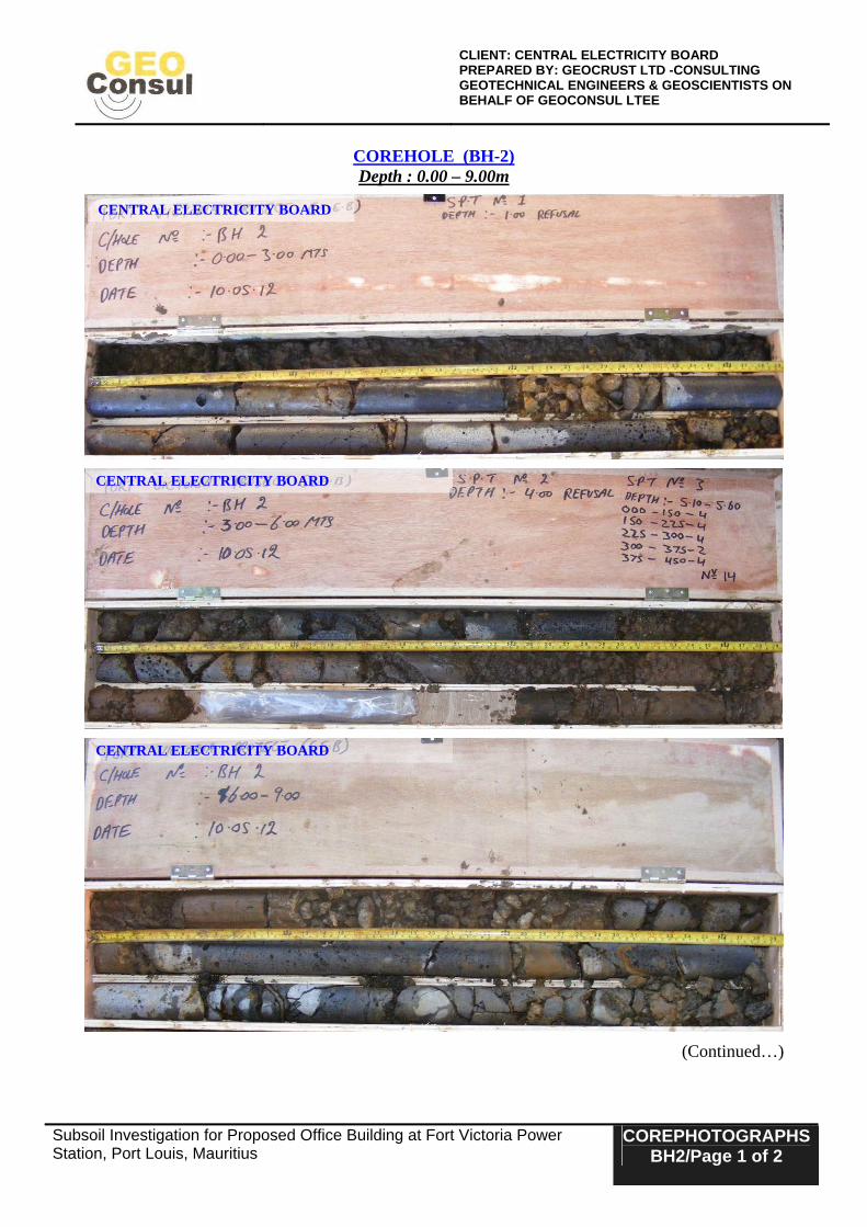
4.55-6.75mVery weak to weak (VW-W)/medium dense, dark brownish with occassional discolouration, medium grained AGGLOMERATE PLUS BASALT mixture in form of clayey silt gravel cobble form, completely weathered (CW) to residual grade, fracture characteristics unable identify due to weathered condition, some parts crushed in drilling in form of gravel cobble form.
0.0-1.00mFirm, dark greyish brown GRAVELLY SILT with plant roots (FILL)
1.00-4.55mStrong (S) with occassional moderately weak layers (MW), light grey to light purple with yellowish discolurations,medium grained, vesicular to non-vesicular BASALT, highly weathered (HW), may be basalt boulder (?1.0-1.8m)
Cas
ing
Siz
e an
d P
rogr
ess
Dep
th (m
)
Dril
ling
Run
& F
luid
use
d fo
r dril
ling
Pen
etra
tion
Tim
e (m
in) P
er
Run
Tota
l Cor
e R
ecov
ery
TCR
(%
)
Sol
id C
ore
Rec
over
y S
CR
(%
)R
ock
Qua
lity
Des
igna
tion
(R.Q
.D %
)
In-s
itu T
est
(SP
T/P
erm
eabi
lity
Test
)
Sam
ples
for L
abor
ator
y Te
st
Frac
ture
Fre
quen
cy p
er m
STRATA DESCRIPTIONS (Soil / Rock)
Elev
atio
n (m
) fro
m G
ound
Le
vel (
GL)
Sym
bolic
Log
Stan
dpip
e Pi
ezom
eter
(if
any)
6.5 CONTINUED FROM PREVIOUS PAGE 6.56.6 6.6 v+v6.7 6.7 ooo6.8 D 80 0 0 6.8 v+v6.9 6.9 vvv7.0 NI 7.0 vvv7.1 7.1 vvv7.2 7.2 vvv7.3 7.3 vvv7.4 7.4 vvv7.5 7.5 vvv7.6 7.6 vvv7.7 7.7 vvv7.8 7.8 vvv7.9 7.9 vvv8.0 W 90 63 29 >10 8.0 vvv8.1 8.1 vvv8.2 8.2 vvv8.3 8.3 vvv8.4 8.4 vvv8.5 8.5 vvv8.6 8.6 vvv8.7 8.7 vvv8.8 8.8 vvv8.9 8.9 vvv9.0 W 85 30 12 >10 9.0 vvv9.1 9.1 v+v9.2 9.2 ooo9.3 9.3 v+v9.4 9.4 v+v9.5 9.5 ooo9.6 9.6 v+v9.7 9.7 v+v9.8 9.8 ooo9.9 9.9 v+v
10.0 W 70 0 0 NI 10.0 v+v10.1 SPT-3 N 10.1 ooo10.2 10.2 v+v10.3 10.3 ooo10.4 10.4 v+v10.5 40 10.5 v+v10.6 10.6 ooo10.7 10.7 v+v10.8 10.8 v+v10.9 10.9 v+v11.0 NI 11.0 ooo11.1 11.1 v+v11.2 11.2 v+v11.3 11.3 v+v11.4 11.4 ooo11.5 11.5 v+v11.6 11.6 v+v11.7 11.7 v+v11.8 11.8 ooo11.9 11.9 v+v12.0 W 80 10 0 NI 12.0 v+v12.1 12.1 vvv12.2 12.2 vvv12.3 12.3 vvv12.4 12.4 vvv12.5 12.5 vvv12.6 12.6 vvv12.7 12.7 vvv12.8 12.8 vvv12.9 12.9 vvv13.0 W 92 63 0 >10 13.0 vvv13.1 13.1 vvv13.2 13.2 vvv13.3 13.3 vvv13.4 13.4 vvv13.5 13.5 vvv13.6 13.6 vvv13.7 13.7 vvv13.8 13.8 vvv13.9 13.9 vvv14.0 W 92 52 26 >10 14.0 vvv
(Continued in Next Page)
Sheet: 2 / 3BH-2
COREHOLE LOGGING: BH-2D
ownh
ole
Dril
ling
Dep
th
(m)
Cha
nge
of S
trat
a (m
) fr
om E
xist
ing
GL
Consulting Geotechnical Engineers & Geoscientists
Subsoil Investigation at Fort Victoria, Port Louis, Mauritius (RFQ NO: Q10836)Geotechnical Drilling
Contractor
Prepared By CLIENT: CENTRAL ELECTRICITY BOARD
9.00-12.00mVery weak to moderately weak (VW-MW)/Dense with occassional moderately strong (MS) layers, light grey with browinish stained with occassional discolourations, medium grained AGGLOMERATE PLUS BASALT mixture in form of gravel cobble form, completely weathered (CW), fracture characteristics unable identify due to completely weathered condition, some parts crushed in drilling in form of gravel cobble form.
12.00-15.00mModerately strong to strong (MS-S) with occassional weak layers (W), light grey to light purple with yellowish discolurations and brownish stained, medium grained, vesicular and non-vesicular BASALT, highly to completely weathered (HW-CW), 1 set of joint, dipping @60-90 degree, medium joint spacing, joint surface planar to rough.
6.75-9.00mModerately strong to strong (MS-S) with occassional moderately weak layers (MW), light grey to purple with yellowish discolurations, fine to medium grained, mostly vesicular BASALT, moderately weathered to highly weathered (MW-HW), 2 sets of joints, dipping @0-30 & 60-90 degree, close to medium joint spacing, joint surface planar to rough.

Cas
ing
Siz
e an
d P
rogr
ess
Dep
th (m
)
Dril
ling
Run
& F
luid
use
d fo
r dril
ling
Pen
etra
tion
Tim
e (m
in) P
er
Run
Tota
l Cor
e R
ecov
ery
TCR
(%
)
Sol
id C
ore
Rec
over
y S
CR
(%
)R
ock
Qua
lity
Des
igna
tion
(R.Q
.D %
)
In-s
itu T
est
(SP
T/P
erm
eabi
lity
Test
)
Sam
ples
for L
abor
ator
y Te
st
Frac
ture
Fre
quen
cy p
er m
STRATA DESCRIPTIONS (Soil / Rock)
Elev
atio
n (m
) fro
m G
ound
Le
vel (
GL)
Sym
bolic
Log
Stan
dpip
e Pi
ezom
eter
(if
any)
14.0 CONTINUED FROM PREVIOUS PAGE 14.014.1 14.1 vvv14.2 14.2 vvv14.3 14.3 vvv14.4 14.4 vvv14.5 14.5 vvv14.6 14.6 vvv14.7 14.7 vvv14.8 14.8 vvv14.9 14.9 vvv15.0 W 90 64 10 >10 15.0 vvv
RemarksEND OF COREHOLE
7. No Piezometer Installed & Borehole was not collapsed 8. NI: NON INTACT
BH-2Sheet: 3 / 3
Notes 1. D stands for dry coring 2. W stands for water used a drilling media3. N/A : Not applicable4. Open hole drilling: 10.00-15.00m (No casing) & Casing= 0.00-10.00m (NX Casing). 5. RF=Refusal, SPT blow count, when full penetration of 450mm is not achieved. 6. N-SPT blow count to achieve penetration of 300mm.
Date Depth (m) Casing (m) Water Level (m)10-May-12 15 10 3.9
COREHOLE LOGGING: BH-2
End of Corehole BH-2 @ 15.00m.
Geotechnical Drilling Contractor
Prepared By CLIENT: CENTRAL ELECTRICITY BOARD
Consulting Geotechnical Engineers & Geoscientists
Subsoil Investigation at Fort Victoria, Port Louis, Mauritius (RFQ NO: Q10836)
Cha
nge
of S
trat
a (m
) fr
om E
xist
ing
GL
Dow
nhol
e D
rillin
g D
epth
(m
)
CLIENT: CENTRAL ELECTRICITY BOARD PREPARED BY: GEOCRUST LTD -CONSULTING GEOTECHNICAL ENGINEERS & GEOSCIENTISTS ON BEHALF OF GEOCONSUL LTEE
Subsoil Investigation for Proposed Office Building at Fort Victoria Power Station, Port Louis, Mauritius
COREHOLE (BH-2) Depth : 0.00 – 9.00m
CENTRAL ELECTRICITY BOARD
CENTRAL ELECTRICITY BOARD
CENTRAL ELECTRICITY BOARD
(Continued…)
COREPHOTOGRAPHSBH2/Page 1 of 2

CLIENT: CENTRAL ELECTRICITY BOARD PREPARED BY: GEOCRUST LTD -CONSULTING GEOTECHNICAL ENGINEERS & GEOSCIENTISTS ON BEHALF OF GEOCONSUL LTEE
Subsoil Investigation for Proposed Office Building at Fort Victoria Power Station, Port Louis, Mauritius
COREHOLE (BH-2) Depth : 9.00 – 15.00m
CENTRAL ELECTRICITY BOARD
CENTRAL ELECTRICITY BOARD
END OF CORE HOLE BH2 @ 15M
COREPHOTOGRAPHSBH2/Page 2 of 2
Logged By & Reviewed By: GK & CA Collar Coordinates: Not AvailableDate of Logged: May 12, 2012 Collar Elevation (m): Not AvailableDate of Photograph: May 12, 2012 Drilling Rig: APAFOR 560 Drilled By: JL
Location: Fort Victoria Power Station, Port Louis Drilling Started: May 11, 2012 Dia. Of Hole: 88.9mmDrilling Method:Rotary Diamond Core using NMLC Drilling Completed: May 11, 2012 Depth: 15.00m
Cas
ing
Siz
e an
d P
rogr
ess
Dep
th (m
)
Dril
ling
Run
& F
luid
use
d fo
r dril
ling
Pen
etra
tion
Tim
e (m
in)
Per
Run
Tota
l Cor
e R
ecov
ery
TCR
(%
)
Sol
id C
ore
Rec
over
y S
CR
(%
)R
ock
Qua
lity
Des
igna
tion
(R.Q
.D %
)
In-s
itu T
est
(SP
T/P
erm
eabi
lity
Test
)
Sam
ples
for L
abor
ator
y Te
st
Frac
ture
Fre
quen
cy p
er m
STRATA DESCRIPTIONS (Soil / Rock)
Elev
atio
n (m
) fro
m
Gou
nd L
evel
(GL)
Sym
bolic
Log
Stan
dpip
e Pi
ezom
eter
(if
any)
0.0 EXISTING GROUND LEVEL 0.0 0.1 0.1 xoxox0.2 0.2 xoxox0.3 0.3 xoxox0.4 0.4 xoxox0.5 0.5 xoxox0.6 0.6 xoxox0.7 0.7 xoxox0.8 0.8 xoxox0.9 0.9 xoxox1.0 D 70 0 0 NI 1.0 xoxox1.1 SPT-1 N 1.1 xoxox1.2 1.2 xoxox1.3 1.3 xoxox1.4 1.4 xoxox1.5 43 1.5 xoxox1.6 1.6 vvv1.7 1.7 vvv1.8 1.8 vvv1.9 1.9 vvv2.0 NI 2.0 vvv2.1 2.1 vvv2.2 2.2 vvv2.3 2.3 vvv2.4 2.4 vvv2.5 W 80 20 0 2.5 vvv2.6 2.6 vvv2.7 2.7 vvv2.8 2.8 vvv2.9 2.9 vvv3.0 >10 3.0 vvv3.1 3.1 vvv3.2 3.2 vvv3.3 3.3 vvv3.4 3.4 vvv3.5 W 90 67 58 3.5 vvv3.6 3.6 vvv3.7 3.7 vvv3.8 3.8 vvv3.9 3.9 vvv4.0 >10 4.0 vvv4.1 4.1 vvv4.2 4.2 vvv4.3 4.3 vvv4.4 4.4 vvv4.5 4.5 vvv4.6 4.6 v+v4.7 4.7 v+v4.8 4.8 ooo4.9 4.9 v+v5.0 W 80 25 15 NI 5.0 v+v5.1 5.1 v+v5.2 5.2 v+v5.3 D 80 0 0 5.3 v+v5.4 SPT-2 N 5.4 v+v5.5 5.5 v+v5.6 5.6 v+v5.7 5.7 ooo5.8 33 5.8 v+v5.9 5.9 v+v6.0 D 80 0 0 NI 6.0 v+v6.1 6.1 ooo6.2 6.2 v+v6.3 6.3 v+v6.4 6.4 vvv6.5 6.5 vvv
(Continued in Next Page)
Dow
nhol
e D
rillin
g D
epth
(m
)
Cha
nge
of S
trat
a (m
) fr
om E
xist
ing
GL
BH-3Sheet: 1 / 3
Sheet: 1 OF 3
CLIENT: CENTRAL ELECTRICITY BOARD
Consulting Geotechnical Engineers & Geoscientists
Subsoil Investigation at Fort Victoria, Port Louis, Mauritius (RFQ NO: Q10836)
COREHOLE LOGGING: BH-3
Geotechnical Drilling Contractor
Prepared By
4.50-6.31mVery weak to weak (VW-W)/Dense, grey to dark brown with yellowish discolouration, fine to medium grained AGGLOMERATE PLUS BASALT mixture in form of clayey silt gravel cobble form, completely weathered to residual grade, fracture characteristics unable identify due to weathered condition, some parts crushed in drilling in form of gravel cobble form.
0.0-1.50mLoose to dense, dark greyish brown SILTY GRAVEL(FILL)
1.50-4.50mStrong (S) with occassional moderately weak layers (MW), light grey to light purple with yellowish discolurations,medium grained, vesicular to non-vesicular BASALT, highly weathered (HW).

Cas
ing
Siz
e an
d P
rogr
ess
Dep
th (m
)
Dril
ling
Run
& F
luid
use
d fo
r dril
ling
Pen
etra
tion
Tim
e (m
in) P
er
Run
Tota
l Cor
e R
ecov
ery
TCR
(%
)
Sol
id C
ore
Rec
over
y S
CR
(%
)R
ock
Qua
lity
Des
igna
tion
(R.Q
.D %
)
In-s
itu T
est
(SP
T/P
erm
eabi
lity
Test
)
Sam
ples
for L
abor
ator
y Te
st
Frac
ture
Fre
quen
cy p
er m
STRATA DESCRIPTIONS (Soil / Rock)
Elev
atio
n (m
) fro
m G
ound
Le
vel (
GL)
Sym
bolic
Log
Stan
dpip
e Pi
ezom
eter
(if
any)
6.5 CONTINUED FROM PREVIOUS PAGE 6.56.6 6.6 vvv6.7 6.7 vvv6.8 6.8 vvv6.9 6.9 vvv7.0 >10 7.0 vvv7.1 7.1 vvv7.2 7.2 vvv7.3 7.3 vvv7.4 W 80 34 0 7.4 vvv7.5 7.5 vvv7.6 7.6 vvv7.7 7.7 vvv7.8 7.8 vvv7.9 7.9 vvv8.0 >10 8.0 vvv8.1 8.1 vvv8.2 8.2 vvv8.3 8.3 vvv8.4 8.4 ooo8.5 W 80 49 10 8.5 v+v8.6 8.6 v+v8.7 8.7 ooo8.8 8.8 ooo8.9 8.9 v+v9.0 >10 9.0 v+v9.1 9.1 ooo9.2 9.2 ooo9.3 9.3 v+v9.4 9.4 v+v9.5 9.5 ooo9.6 9.6 ooo9.7 9.7 v+v9.8 9.8 v+v9.9 9.9 ooo
10.0 W 80 5 0 NI 10.0 ooo10.1 10.1 v+v10.2 10.2 v+v10.3 10.3 ooo10.4 10.4 vvv10.5 10.5 vvv10.6 10.6 vvv10.7 10.7 vvv10.8 10.8 vvv10.9 10.9 vvv11.0 W 80 53 0 >10 11.0 vvv11.1 11.1 vvv11.2 11.2 vvv11.3 11.3 vvv11.4 11.4 vvv11.5 11.5 vvv11.6 11.6 vvv11.7 11.7 vvv11.8 11.8 vvv11.9 11.9 vvv12.0 W 80 45 12 >10 12.0 vvv12.1 12.1 vvv12.2 12.2 vvv12.3 12.3 vvv12.4 12.4 vvv12.5 12.5 vvv12.6 12.6 vvv12.7 12.7 vvv12.8 12.8 vvv12.9 12.9 vvv13.0 W 90 53 0 >10 13.0 vvv13.1 13.1 vvv13.2 13.2 vvv13.3 13.3 vvv13.4 13.4 vvv13.5 13.5 vvv13.6 13.6 vvv13.7 13.7 vvv13.8 13.8 vvv13.9 13.9 vvv14.0 W 85 48 0 >10 14.0 vvv
(Continued in Next Page)
Consulting Geotechnical Engineers & Geoscientists
Subsoil Investigation at Fort Victoria, Port Louis, Mauritius (RFQ NO: Q10836)Geotechnical Drilling
Contractor
Prepared By CLIENT: CENTRAL ELECTRICITY BOARD
Sheet: 2 / 3BH-3
COREHOLE LOGGING: BH-3D
ownh
ole
Dril
ling
Dep
th
(m)
Cha
nge
of S
trat
a (m
) fr
om E
xist
ing
GL
6.31-8.27mModerately strong to strong (MS-S) with occassional weak layers (W), light to dark grey with occasional discolurations, fine to medium grained, mostly vesicular BASALT, highly weathered (HW).
8.27-10.30mWeak to moderately strong (W-MS), light grey with yellowish discolouration as well as brownish stained, medium grained AGGLOMERATE PLUS BASALT mixture in form of gravel cobble form, highly weathered to completely weathered (HW-CW), fracture characteristics unable identify due to weathered condition, some parts crushed in drilling in form of gravel cobble form.
10.30-15.00mModerately strong to strong (MS-S) with occassional weak layers (W), light grey to light purple with yellowish discolurations and occassional brownish stained, medium grained, mostly vesicular BASALT, highly weathered (HW), 2 sets of joints, dipping @0-30 & 60-90 degree, medium joint spacing, joint surface planar to rough.

Cas
ing
Siz
e an
d P
rogr
ess
Dep
th (m
)
Dril
ling
Run
& F
luid
use
d fo
r dril
ling
Pen
etra
tion
Tim
e (m
in) P
er
Run
Tota
l Cor
e R
ecov
ery
TCR
(%
)
Sol
id C
ore
Rec
over
y S
CR
(%
)R
ock
Qua
lity
Des
igna
tion
(R.Q
.D %
)
In-s
itu T
est
(SP
T/P
erm
eabi
lity
Test
)
Sam
ples
for L
abor
ator
y Te
st
Frac
ture
Fre
quen
cy p
er m
STRATA DESCRIPTIONS (Soil / Rock)
Elev
atio
n (m
) fro
m G
ound
Le
vel (
GL)
Sym
bolic
Log
Stan
dpip
e Pi
ezom
eter
(if
any)
14.0 CONTINUED FROM PREVIOUS PAGE 14.014.1 14.1 vvv14.2 14.2 vvv14.3 14.3 vvv14.4 14.4 vvv14.5 14.5 vvv14.6 14.6 vvv14.7 14.7 vvv14.8 14.8 vvv14.9 14.9 vvv15.0 W 90 74 12 >10 15.0 vvv
RemarksEND OF COREHOLE
COREHOLE LOGGING: BH-3
End of Corehole BH-3 @ 15.00m.
Geotechnical Drilling Contractor
Prepared By CLIENT: CENTRAL ELECTRICITY BOARD
Consulting Geotechnical Engineers & Geoscientists
Subsoil Investigation at Fort Victoria, Port Louis, Mauritius (RFQ NO: Q10836)
Cha
nge
of S
trat
a (m
) fr
om E
xist
ing
GL
Dow
nhol
e D
rillin
g D
epth
(m
)
Notes 1. D stands for dry coring 2. W stands for water used a drilling media3. N/A : Not applicable4. Open hole drilling: 5.30-15.00m (No casing) & Casing= 0.00-5.30m (NX Casing). 5. RF=Refusal, SPT blow count, when full penetration of 450mm is not achieved. 6. N-SPT blow count to achieve penetration of 300mm.
Date Depth (m) Casing (m) Water Level (m)11-May-12 15 5.3 4
7. No Piezometer Installed No Piezometer Installed & Borehole was not collapsed 8. NI: NON INTACT
BH-3Sheet: 3 / 3

CLIENT: CENTRAL ELECTRICITY BOARD PREPARED BY: GEOCRUST LTD -CONSULTING GEOTECHNICAL ENGINEERS & GEOSCIENTISTS ON BEHALF OF GEOCONSUL LTEE
Subsoil Investigation for Proposed Office Building at Fort Victoria Power Station, Port Louis, Mauritius
COREHOLE (BH-3) Depth : 0.00 – 9.00m
CENTRAL ELECTRICITY BOARD
CENTRAL ELECTRICITY BOARD
CENTRAL ELECTRICITY BOARD
(Continued…)
COREPHOTOGRAPHSBH3/Page 1 of 2

CLIENT: CENTRAL ELECTRICITY BOARD PREPARED BY: GEOCRUST LTD -CONSULTING GEOTECHNICAL ENGINEERS & GEOSCIENTISTS ON BEHALF OF GEOCONSUL LTEE
Subsoil Investigation for Proposed Office Building at Fort Victoria Power Station, Port Louis, Mauritius
COREHOLE (BH-3) Depth : 9.00 – 15.00m
CENTRAL ELECTRICITY BOARD
CENTRAL ELECTRICITY BOARD
END OF CORE HOLE BH3 @ 15M
COREPHOTOGRAPHSBH3/Page 2 of 2

EXCAVATION METHOD: Mechanical DATE COMMENCED: May 16, 2012DATE COMPLETED: May 16, 2012 REVIEWED BY: CA
X Not Availlable CONTRACTOR: GEOCONSUL
Y Not AvailableLOCATION : Fort Victoria Power Station, Port Louis SUPPORT: Not required Z(m) Not Available
Laboratory test results HOLE
% fines Atterberg limits MC / LS Test DIG RATE DEPTH BSC
-75um LL (%) PI(%) (%) Results (m)
0.1
0.2
0.3
0.4 ===='
0.5 ====' 0.50.6 ===='
0.7 ===='
0.8 ====' 0.9 ===='
1.0 ====' 184.5 34.7
1.1 o-o-o- 1.51.2 o-o-o-1.3 vvv
1.4 v+v
1.5 vvv 1.6 v+v
1.7 vvv
1.8 v+v
1.9 vvv
2.0 v+v 2.1 vvv
2.2 v+v
2.3 vvv 2.4 v+v
2.5 vvv 2.6 v+v
2.7 vvv Dry
sampling B bulk sample D disturbed sample (sample number in brackets) T tube sample (sample number in brackets) D*, T* no recovery field tests permeability cons=constant head fall=falling headrise=rising head test
= Ground water Level Sheet 1 of 1
Geotechnical Drilling Contractor
Consulting Geotechnical Engineers & Geoscientists
GEOTECHNICAL LOG OF TEST PIT/EXCAVATIONTest Pit No:
TP-1
CLIENT : CENTRAL ELECTRICITY BOARD
PROJECT:SUBSOIL INVESTIGATION AT FORT
VICTORIA, PORT LOUIS, MAURITIUS (RFQ NO: Q10836)
MACHINE: JCB 3CXWIDTH: 1.5 (m)
CO-ORDINATES:LENGTH: 2.8 (m)
LOGGED BY:GK
DEPTH: 2.7 (m)
D
End of Trial Pit at 2.7m Depth
S F
Site activities
Samples:Elevation(m)
Gra
phic
Log
Type M
Poc
ket
Pen
etro
met
er
(PP
:Kg/
cm2 )
MATERIAL DESCRIPTION (DESCRIPTION OF STRATA)
Gro
und-
wat
er
Notes 1.Groundwater : Dry 2.Dimension of pit: 2.80m x 1.50m x 2.70m 3.Excavator used for excavation: JCB 3CX 4. Weather condition: SUNNY 5.D Sample Taken for Laboratory Test : Big bag sample taken @ 1.1m 6.Photograph of Trial Pit Profile up to 2.7m 7. Insitu Test: Not Applicable
8. MC = Moisture Content 9. GR = Grading 10. AL = Atterberg Limit 11. C = Compaction 12. BSC=British Soil Classification 13.Dig Rate (S): Slow 14. Dig Rate (M): Moderate 15. Dig Rate (F): Fast 16. PP: Pocket Penetrometer Reading
1.00 - 1.20m Stiff, damp to slight moist, light brown colour GRAVELLY CLAY with some silt occassional cobble from basalt rock in the matrix of clayey silt, PP=1.50kg/cm2.
0.0-0.30m TOP SOIL: Firm, dark greyish brown, dry, GRAVELLY SILT with plant roots (TOP SOIL)
0.30 - 1.00m UNCONTROLLED FILL- Loose to medium dense, greyish black colour, silty gravel cobble plus buried pipes.
1.20 - 2.70m Strong(S), greyish to brown with yellowish discolourisation, vesicular BASALTIC BOULDERS, highly weathered (HW) in the matrix of clayey silt.

CLIENT: CENTRAL ELECTRICITY BOARD PREPARED BY: GEOCRUST LTD -Consulting Geotechnical Engineers & Geoscientists on behalf of Geoconsul Ltee
Photographs Page 1 of 1
Subsoil Investigation at Fort Victoria, Port Louis, Mauritius (RFQ NO: Q10836)
TRIAL PIT NO.1 Depth: 0.0 – 2.7 meters
TP-1 NORTH
TP-1 EAST
TP-1 SOUTH
TP-1 WEST

Appendix C
Laboratory Test Results Soil Mechanics Test Chemical Analysis of Water Sample
Subsoil Investigation at Fort Victoria, Port Louis, Mauritius (RFQ NO: Q10836)