final report guide iii guide to road slope protection -...
TRANSCRIPT
JAPAN INTERNATIONAL COOPERATION AGENCY
THE DEPARTMENT OF PUBLIC WORKS AND HIGHWAYS
THE STUDY ON RISK MANAGEMENT FOR SEDIMENT-RELATED DISASTER ON SELECTED NATIONAL HIGHWAYS IN THE
REPUBLIC OF THE PHILIPPINES
FINAL REPORT GUIDE III
GUIDE TO ROAD SLOPE PROTECTION
2007 Joint Venture
ofNippon Koei Co. Ltd. and OYO International Corporation

The Study on Risk Management for Sediment-Related Disaster on Final Report Guide III Selected National Highways in the Republic of the Philippines Road Slope Protection
NIPPON KOEI CO., LTD. June 2007 OYO INTERNATIONAL CORPORATION
i
GUIDE III ROAD SLOPE PROTECTION
Table of Contents
CHAPTER 1 INTRODUCTION ............................................................................1-1
1.1 General ..................................................................................................1-1 1.2 Policy on Editing this Guide...................................................................1-1 1.3 Outline of the Guide ...............................................................................1-2
CHAPTER 2 BASIC APPROACHES TO THE MITIGATION OF ROAD
SLOPE DISASTERS ........................................................................2-1 2.1 Classification of Road Slope Disasters ..................................................2-1 2.1.1 Soil Slope Collapse (SC)...........................................................2-2 2.1.2 Rock Slope Collapse (RC) ........................................................2-3 2.1.3 Landslide (LS) ..........................................................................2-3 2.1.4 Road Slip (RS)..........................................................................2-4 2.1.5 Debris Flow (DF)......................................................................2-5 2.1.6 River Erosion (RE) ...................................................................2-5 2.1.7 Costal Erosion (CE) ..................................................................2-6 2.2 Characteristics of Road Slope Disasters ................................................2-6 2.2.1 Soil Slope Collapse...................................................................2-6 2.2.2 Rock Slope Collapse .................................................................2-8 2.2.3 Landslides ................................................................................2-9 2.2.4 Road Slips ................................................................................2-10 2.2.5 Debris Flow ..............................................................................2-11 2.2.6 River Erosion............................................................................2-12 2.2.7 Costal Erosion ..........................................................................2-12 2.3 Main Factors Causing Road Slope Disasters...........................................2-13
CHAPTER 3 COUNTERMEASURE AGAINST SOIL SLOPE
COLLAPSES ....................................................................................3-1 3.1 General ..................................................................................................3-1 3.2 General Policy for Stabilization of Soil Slopes.......................................3-1 3.3 Design for Standard Slope (Cut Slope)...................................................3-2
3.3.1 Standard Gradient of Cut Slopes ...............................................3-2 3.3.2 Berms of Cut Slopes .................................................................3-3 3.3.3 Survey Checkpoints for Cut Slopes...........................................3-4 3.3.4 Cuts Requiring Caution ............................................................3-4
3.4 Surface Drainage ...................................................................................3-5 3.4.1 Design Conditions ....................................................................3-5 3.4.2 Design of Surface Drainage ......................................................3-7
3.5 Selection of Countermeasures................................................................3-10 3.5.1 Classification of Countermeasures ............................................3-10
The Study on Risk Management for Sediment-Related Disaster on Final Report Guide III Selected National Highways in the Republic of the Philippines Road Slope Protection
NIPPON KOEI CO., LTD. June 2007 OYO INTERNATIONAL CORPORATION
ii
3.5.2 Criteria for Selection of Countermeasures.................................3-11 3.6 Design of Main Countermeasures ..........................................................3-13
3.6.1 Vegetation.................................................................................3-13 3.6.2 Retaining Walls ........................................................................3-15 3.6.3 Pitching Works .........................................................................3-20 3.6.4 Crib Works ...............................................................................3-21 3.6.5 Rock Bolts with Concrete Crib Works.......................................3-23
CHAPTER 4 COUTERMEASURES AGAINST ROCK SLOPE
COLLAPSE.......................................................................................4-1 4.1 General ..................................................................................................4-1 4.2 Calculation of Impact Force of Falling Rocks.........................................4-1
4.2.1 Motion Mechanism of Rock Falls .............................................4-1 4.2.2 Velocity of Falling Rocks..........................................................4-2 4.2.3 Kinetic Energy of Falling Rocks ...............................................4-3 4.2.4 Impact Force of Falling Rocks ..................................................4-4
4.3 Selection of Countermeasures ................................................................4-5 4.3.1 Classification of Countermeasures ............................................4-5 4.3.2 Criteria for Selection of Countermeasures.................................4-6
4.4 Design of Main Countermeasures ..........................................................4-9 4.4.1 Removing and Cutting ..............................................................4-9 4.4.2 Rock Fall Catch Nets ................................................................4-10 4.4.3 Rock Fall Catch Fences ............................................................4-12 4.4.4 Rock Sheds...............................................................................4-15 4.4.5 Catch Fill and Ditches...............................................................4-18
CHAPTER 5 COUNTERMEASURES AGAINST LANDSLIDES.......................5-1
5.1 General ..................................................................................................5-1 5.2 Key Points of Reconnaissance for Formulating Landslide
Countermeasure Plans ............................................................................5-1 5.3 Stability Analysis of Slopes ....................................................................5-2
5.3.1 Stability Analysis ......................................................................5-2 5.3.2 Parameters of Shear Strength of Sliding Surface .......................5-5 5.3.3 Determination of Initial Factor of Safety...................................5-6 5.3.4 Determination of Proposed Factor of Safety..............................5-6 5.3.5 Sliding Surface .........................................................................5-7
5.4 Selection of Countermeasures................................................................5-8 5.4.1 Classification of Countermeasures ............................................5-8 5.4.2 Criteria for Selection of Countermeasures.................................5-9
5.5 Design of Main Countermeasures ..........................................................5-10 5.5.1 Cutting Work ............................................................................5-10 5.5.2 Filling Work .............................................................................5-12 5.5.3 Surface Drainage ......................................................................5-13 5.5.4 Horizontal Drain Hole ..............................................................5-15 5.5.5 Drainage Wells .........................................................................5-16 5.5.6 Ground Anchors........................................................................5-19 5.5.7 Steel Pipe Piles .........................................................................5-24
The Study on Risk Management for Sediment-Related Disaster on Final Report Guide III Selected National Highways in the Republic of the Philippines Road Slope Protection
NIPPON KOEI CO., LTD. June 2007 OYO INTERNATIONAL CORPORATION
iii
CHAPTER 6 COUNTERMEASURES AGAINST ROAD SLIPS ..........................6-1 6.1 General ...................................................................................................6-1 6.2 General Policy for Design of Stable Road Shoulders...............................6-1 6.3 Selection of Countermeasures .................................................................6-2
6.3.1 Classification of Countermeasures ............................................6-2 6.3.2 Criteria for Selection of Countermeasures.................................6-3
6.4 Design of Main Countermeasures ...........................................................6-6 6.4.1 Reinforced Earth Walls .............................................................6-6 6.4.2 Sand Bag Walls.........................................................................6-11
CHAPTER 7 COUNTERMEASURES AGAINST DEBRIS FLOW ..................7-1
7.1 General..................................................................................................7-1 7.2 Selection of Countermeasures................................................................7-1
7.2.1 Classification of Countermeasures ............................................7-1 7.2.2 Criteria for Selection of Countermeasures.................................7-3
7.3 Design of Main Countermeasures ..........................................................7-6 7.3.1 Sabo Dam for Debris Flow .......................................................7-6 7.3.2 Causeways................................................................................7-11
CHAPTER 8 COUNTERMEASURES AGAINST RIVER EROSION ..............8-1
8.1 General..................................................................................................8-1 8.2 Selection of Countermeasures................................................................8-2
8.2.1 Classification of Countermeasures ............................................8-2 8.2.2 Criteria for Selection of Countermeasures.................................8-4
8.3 Design of Main Countermeasures ..........................................................8-6 8.3.1 Revetments...............................................................................8-6 8.3.2 Groundsills ...............................................................................8-9
CHAPTER 9 COUNTERMEASURES AGAINST COASTAL EROSION...........9-1 9.1 General..................................................................................................9-1 9.2 Selection of Countermeasures................................................................9-3 9.3 Design of Coastal Slope Revetments......................................................9-5 9.3.1 General ..........................................................................................9-5 9.3.2 Type of Revetment Structure..........................................................9-7
9.3.3 Design Crest Elevation of the Revetment .......................................9-10 9.3.4 Gradient of Slope Revetment .........................................................9-11 9.3.5 Stability of Bank Body...................................................................9-12 9.3.6 Structural Details ...........................................................................9-14
CHAPTER 10 EXAMPLES OF COUNTERMEASURE DESIGN .......................10-1
10.1 General..................................................................................................10-1 10.2 Examples of Countermeasure Design in the Philippines.........................10-1
10.2.1 Road slips-Delton Pass Road Km 211 (Region II) ................10-1 10.2.2 Road slips-Kennon Road Km 232 (Region CAR).................10-13 10.2.3 Landslide-Wright-Taft, Km 846 (Region VIII) .....................10-28 10.2.4 Landslide-Lagawe-Banaue Road, Km 301
The Study on Risk Management for Sediment-Related Disaster on Final Report Guide III Selected National Highways in the Republic of the Philippines Road Slope Protection
NIPPON KOEI CO., LTD. June 2007 OYO INTERNATIONAL CORPORATION
iv
(Region CAR).........................................................................10-47 10.2.5 Coastal Erosion-Ginatilan-Alegria Road Km172 (Region VII) .........................................................................10-65 10.2.6 River Erosion-Naga-Toledo Road No.2, Sta.2+600~2+890..................................................................10-69
10.3 Examples of Countermeasure Design in Japan .......................................10-71 10.3.1 Soil Slope Collapse.................................................................10-71 10.3.2 Landslide ................................................................................10-76 10.3.3 Rock Fall on Primary Local Road ...........................................10-82
CHAPTER 11 TEMPORARY TREATMENT FOR ROAD SLOPE DISASTERS AND QUALITY CONTROL OF RESTORATION WORKS................................................................11-1
11.1 General....................................................................................................11-1 11.2 Temporary Treatment...............................................................................11-2 11.2.1 Classification of Temporary Measures............................................11-2 11.2.2 Emergency Countermeasure...........................................................11-5 11.3 Quality Control of Restoration Works ......................................................11-13 11.3.1 Slope Cutting and Flattening Works ...............................................11-13 11.3.2 Slope Protection Works ..................................................................11-21 11.3.3 Retaining Structures.......................................................................11-37 11.3.4 Horizontal Drain Holes ..................................................................11-46
Appendix -1 References Appendix-2 Sources for Main Equations Used in This Guide III
The Study on Risk Management for Sediment-Related Disaster on Final Report Guide III Selected National Highways in the Republic of the Philippines Road Slope Protection
NIPPON KOEI CO., LTD. June 2007 OYO INTERNATIONAL CORPORATION
v
List of Tables Page
Table 2.1 Comparisons between the Revised and Previous Classification ................ 2-2 Table 2.2 Factors Causing Slope Instability ........................................................... 2-14 Table 3.1 Geometric Standards for Cut Slopes......................................................... 3-2 Table 3.2 Coefficient of Runoff by Ground Surface Conditions ............................... 3-6 Table 3.3 Standard Probable of Rainfall Return Period to be Applied .................... 3-6 Table 3.4 Classification of Countermeasures against Soil Slope Collapse .............. 3-10 Table 3.5 General Selection Criteria for Vegetation ............................................... 3-14 Table 3.6 Types and Characteristics of Retaining Wall........................................... 3-16 Table 3.7 Standard Dimension of Stone or Concrete Block Retaining Walls .......... 3-17 Table 3.8 Standard Dimension of Leaning Retaining Walls .................................. 3-19 Table 3.9 Determination of Wall Height by Bearing Ground.................................. 3-19 Table 3.10 Selection of Pitching Works ............................................................... 3-21 Table 3.11 Application of Crib Works .................................................................. 3-23 Table 3.12 recommended Internal Friction Angle and Cohesion .......................... 3-24 Table 3.13 Allowable Tensile Stress (σsa) of Rock Bolt Material............................ 3-26 Table 3.14 Allowable bond Stress between Grout and Steel Material ..................... 3-26 Table 3.15 Friction Resistance of Ground with Rock Bolt ................................... 3-27 Table 3.16 Type and Size of Steel Material Used for Different Concrete Cribs ...... 3-29 Table 3.17 Allowable Stress for Concrete (Mortar) Crib ........................................ 3-30 Table 4.1 kinds of Slopes and Values of the Equivalent Coefficient of
Friction ............................................................................................... 4-3 Table 4.2 Lame’s Constant of Shock Absorbing Materials ..................................... 4-5 Table 4.3 Classification of Countermeasures for Rock Falls .................................... 4-5 Table 4.4 Application of Countermeasures for Rock Falls ....................................... 4-9 Table 4.5 Standard Specifications for Rock Fall Catch Fences ............................. 4-15 Table 4.6 Combinations of Loads for Design of Rock Sheds ................................. 4-17 Table 4.7 Recommended Shape and Dimension of Catch Ditches ........................ 4-19 Table 5.1 Vertical Thickness of Sliding Mass and Cohesion ................................... 5-6 Table 5.2 Determination of Initial Factor of Safety ................................................ 5-6 Table 5.3 Determination of Proposed Factor of Safety............................................. 5-7 Table 5.4 Classification of Countermeasures for Landslides .................................... 5-8 Table 5.5 Recommended Standard Fill Slopes ....................................................... 5-12 Table 5.6 Recommended Allowable Adhesive Stresses.......................................... 5-23 Table 5.7 Recommended Skin Frictional Resistance of Anchor ............................. 5-23

The Study on Risk Management for Sediment-Related Disaster on Final Report Guide III Selected National Highways in the Republic of the Philippines Road Slope Protection
NIPPON KOEI CO., LTD. June 2007 OYO INTERNATIONAL CORPORATION
vi
Table 5.8 Items to be Examined............................................................................. 5-25 Table 5.9 Design Condition for Piles ..................................................................... 5-27 Table 5.10 Standard Interval between Piles............................................................ 5-29 Table 5.11 Embedment Length of Piles ................................................................. 5-29 Table 6.1 Classification of Countermeasure for Road Slips ..................................... 6-4 Table 6.2 Application of Countermeasures against Road Slips................................. 6-5 Table 6.3 Typical Reinforced Earth Walls .............................................................. 6-7 Table 6.4 Comparison of Stability Analysis for Typical Methods ........................... 6-9 Table 6.5 Effective Tensile Resistance Force of Typical Reinforcement
Materials............................................................................................. 6-10 Table 6.6Applicability of Backfill Materials...........................................................6-11 Table 6.7Criteria for the Stability Analysis of Sand Bag Walls ............................. 6-13 Table 7.1 Classification of Countermeasures for Debris Flow.................................. 7-2 Table 7.2 Criteria for Stability Analysis of a Dam Body ........................................ 7-10 Table 7.3 Combination of Loads for the Stability Calculation of Dam Body.......... 7-10 Table 8.1 Classification of Countermeasures against River Erosion......................... 8-2 Table 8.2 Relationships between Height, Gradient and Type of Revetments ............ 8-8 Table 8.3 Embedment of Groundsill Wings ........................................................... 8-12 Table 9.1 Slope Revetment Structural Types............................................................ 9-7 Table 9.2 Standard Gradient of Revetment Slope................................................... 9-12 Table 9.3 Creep Ratio with Weighting Factor by Soil Classification ...................... 9-14 Table 9.4 Standard requirements for Typical Slope Revetments............................. 9-15 Table 9.5 KD-value of Rubble Stone by U.S.A Army ............................................ 9-28 Table 9.6 Standard Parameters for Wave Breaking Structures ................................ 9-30 Table 10.1 Allowable Intensity of Stress on Non-reinforced Concretes .................. 10-8 Table 10.2 Summary of External Forces ................................................................ 10-9 Table 10.3 Summary of Stability Calculation Results .......................................... 10-9 Table 10.4 Summary of Bearing Capacity Calculations for the Foundation
Piles.................................................................................................. 10-10 Table 10.5 Summary of Concrete Stress Intensity Calculation Results ............... 10-12 Table 10.6 Allowable Stresses and Safety Factor ................................................. 10-18 Table 10.7 Summary of External Forces for Stability Calculations ...................... 10-27 Table 10.8 Stability Calculation Results .............................................................. 10-27 Table 10.9 Initial Soil Parameters for Circular Sliding Analysis........................... 10-33

The Study on Risk Management for Sediment-Related Disaster on Final Report Guide III Selected National Highways in the Republic of the Philippines Road Slope Protection
NIPPON KOEI CO., LTD. June 2007 OYO INTERNATIONAL CORPORATION
vii
Table 10.10 Summary of External Forces ............................................................ 10-37 Table 10.11 Summary of Stability Calculation Results ....................................... 10-37 Table 10.12 Summary of r Stress Intensity of Reinforcement Concrete................ 10-40 Table 10.13 Delay Coefficient in Kerby Formula for Inflow Time ....................... 10-43 Table 10.14 Coefficient of Roughness (n) for Manning Formula ......................... 10-44 Table 10.15 Design Run-off and Flow Capacity of Drainage Facilities .............. 10-45 Table 10.16 Scale of Landslide Blocks ................................................................ 10-47 Table 10.17 Conditions and Parameters of Stability Analysis by Swedish
Slice Method ......................................................................................... 10-51 Table 10.18 Stability Analysis Result in unit Width ........................................... 10-52 Table 10.19 S Quantities of Horizontal Drain Holes .......................................... 10-57 Table 10.20 C Conditions and Parameters for Pile Design ................................. 10-58 Table 10.21 Pile Type and Allowable Stress ....................................................... 10-58 Table 10.22 Pile Types and their Features............................................................ 10-59 Table 10.23 Coefficient of Horizontal Subgrade Reaction and Modulus of
Deformation...................................................................................... 10-60 Table 10.24βValue of Pile ................................................................................ 10-60 Table 10.25 Sectional Calculation Results ........................................................... 10-61 Table 10.26 Determination of Pile Intervals ....................................................... 10-62 Table 10.27 Determination of Embedment Depth ................................................ 10-63 Table 10.28 Economic Comparison of the Piles................................................... 10-63 Table 10.29 Summary of Steel Pipe Pile Work..................................................... 10-64 Table 10.30 Summary of Slope Conditions ........................................................ 10-83 Table 10.31 Study of Alternative Countermeasures.............................................. 10-85 Table 10.32 Size and Kinetic Energy of Falling Rocks ........................................ 10-85 Table 10.33 Summary of Design Conditions, parameters and Criteria.................. 10-87 Table 10.34 Detailed Specifications of Rock Fall Protection Fence to Be
Used...................................................................................................... 10-88 Table 10.35 Stability Calculation Results of the Planned Concrete Catch Wall .... 10-88 Table 10.36 Summary of Design Conditions, Parameters and Criteria ................. 10-89 Table 10.37 Stability Calculation Results for the Underground Foundation ......... 10-89 Table 11.1 Classification of Temporary Treatment Measures ..................................11-2 Table 11.2 Application Range of Excavation Methods as per Material
Hardness ............................................................................................11-15 Table 11.3 Site Inspection Item of Slope Excavation ............................................11-20 Table 11.4 Standard Criteria for Inspection of Vegetation .....................................11-32 Table 11.5 Classification of Stones for Riprap ......................................................11-37 Table 11.6 Standard Requirements for Geotextile Filter Fabric .............................11-40
The Study on Risk Management for Sediment-Related Disaster on Final Report Guide III Selected National Highways in the Republic of the Philippines Road Slope Protection
NIPPON KOEI CO., LTD. June 2007 OYO INTERNATIONAL CORPORATION
viii
Table 11.7 Standard Dimensions of Mesh Cylinders.............................................11-43 Table 11.8 Standard Dimensions of Wire Mats .....................................................11-43 Table 11.9 Minimum Diameter and Tensile Strength of Galvanized Wire .............11-44 Table 11.10 Minimum Weight of Zinc Coating.....................................................11-44 Table 11.11 Example of Drainage Water Volume Sheet for Horizontal Drain
Holes ...............................................................................................11-47
List of Figures
Page
Figure 2.1 Schematic Illustration of Soil Slope Collapse .......................................... 2-2 Figure 2.2 Schematic Illustration of Rock Slope Collapse......................................... 2-3 Figure 2.3 Schematic Illustration of Landslides ........................................................ 2-4 Figure 2.4 Schematic Illustration of Road Slips ........................................................ 2-4 Figure 2.5 Schematic Illustration of Debris Flow...................................................... 2-5 Figure 2.6 Schematic Illustration of River Erosion ................................................... 2-6 Figure 2.7 Schematic Illustration of Coastal Erosion ................................................ 2-6 Figure 2.8 Soil Slope Collapses Occurring along the National Highways .............. 2-7 Figure 2.9 Rock Slope Collapses Occurring along the National Highways .............. 2-8 Figure 2.10 Examples of Actual Landslides .............................................................. 2-9 Figure 2.11 Examples of Actual Road Slips ............................................................ 2-10 Figure 2.12 Example of Debris Flow on Dalton Pass in Nueva Vizcaya .................2-11 Figure 2.13 Examples of River Erosion .................................................................. 2-12 Figure 2.14 Examples of Coastal Erosion on the Ginalitan-Alegria Road ............... 2-13 Figure 3.1 Conceptual Illustration of a Cut Slope ..................................................... 3-3 Figure 3.2 Countermeasures against Soil Slope Collapses ........................................ 3-5 Figure 3.3 Classifications of Surface Drainage facilities ........................................... 3-7 Figure 3.4 Details of Berm Drain Ditches................................................................. 3-8 Figure 3.5 Structural Image of Drain Ditch............................................................... 3-9 Figure 3.6 Example of Drainage Ditch Layout ........................................................ 3-9 Figure 3.7 Drainage Ditch with Soil-Cement Mixture............................................. 3-10 Figure 3.8 Selection Flowcharts of Countermeasures against Soil Slope
Collapse...............................................................................................3-11 Figure 3.9 Schematic diagrams for Re-cutting Slope .............................................. 3-12 Figure 3.10 Schematic Diagram of Slope Foot Protection....................................... 3-12 Figure 3.11 Schematic Diagram of Anchor and Pile Works..................................... 3-13 Figure 3.12 Typical Vegetation Works .................................................................... 3-14
The Study on Risk Management for Sediment-Related Disaster on Final Report Guide III Selected National Highways in the Republic of the Philippines Road Slope Protection
NIPPON KOEI CO., LTD. June 2007 OYO INTERNATIONAL CORPORATION
ix
Figure 3.13 Example of Gabion Wall on the Foot of a Slope ................................. 3-17 Figure 3.14 Detail of Stone or Concrete Block Retaining Wall ............................... 3-18 Figure 3.15 Structural View of Leaning Retaining Walls......................................... 3-18 Figure 3.16 Detail of Concrete Crib Retaining Wall................................................ 3-20 Figure 3.17 Examples of Pitching Works................................................................ 3-21 Figure 3.18 Details of Cast-in-place Concrete Crib Work ....................................... 3-22 Figure 3.19 Model of soil Slope Collapse and Arrangement of Rock Bolts ............. 3-25 Figure 3.20 Arrangement of Rock Bolt ................................................................... 3-28 Figure 3.21 Model of Design Load......................................................................... 3-28 Figure 4.1 Illustration of Motion Mechanism of Falling Rocks................................. 4-2 Figure 4.2 Motion Pattern of Falling Rocks .............................................................. 4-2 Figure 4.3 Selection Flowchart of Countermeasures for Rock Falls .......................... 4-7 Figure 4.4 Combinations of Countermeasures .......................................................... 4-7 Figure 4.5 Examples of Rock Removal................................................................... 4-10 Figure 4.6 Design of Catch Nets ............................................................................4-11 Figure 4.7 Example of Pocket Type Rock Fall Catch Net ....................................... 4-12 Figure 4.8 Design Flowchart of Rock Fall Catch Fences......................................... 4-14 Figure 4.9 Types of Rock Sheds ............................................................................. 4-15 Figure 4.10 Design Procedure for Rock Sheds........................................................ 4-16 Figure 4.11 Loading Method for Impact Load ........................................................ 4-17 Figure 4.12 Diagrammatic Layout of Catch Fill and Ditch...................................... 4-18 Figure 5.1 Schematic Diagram of Effectiveness of Piling Works .............................. 5-3 Figure 5.2 Schematic Diagram of Effectiveness of Anchor Works ............................ 5-4 Figure 5.3 Schematic Diagram of effectiveness of Drainage Work............................ 5-4 Figure 5.4 Schematic Diagram of effectiveness of Earthworks ............................... 5-5 Figure 5.5 Selection Flowchart of Countermeasures against Landslides .................. 5-9 Figure 5.6 Conceptual Illustration of Cutting Work ...............................................5-11 Figure 5.7 Conceptual Illustration of Filling Work ................................................ 5-13 Figure 5.8 Drainage Channels and Collecting Basins ............................................ 5-14 Figure 5.9 Typical Layout of Horizontal Drain Holes ........................................... 5-16 Figure 5.10 structural Details of Drainage Well .................................................... 5-18 Figure 5.11 Typical Layout of Drainage Well ......................................................... 5-18 Figure 5.12 Landslide Stabilized with Ground Anchors ...................................... 5-19 Figure 5.13 Design Flowchart for Ground Anchors ............................................... 5-20 Figure 5.14 Functional Description of an Anchor .................................................. 5-21 Figure 5.15 Outline of Anchor Structure ............................................................... 5-22 Figure 5.16 Typical Example of Landslide Stabilized by Ground Anchors ............ 5-24
The Study on Risk Management for Sediment-Related Disaster on Final Report Guide III Selected National Highways in the Republic of the Philippines Road Slope Protection
NIPPON KOEI CO., LTD. June 2007 OYO INTERNATIONAL CORPORATION
x
Figure 5.17 Classification of Steel Pipe Piles ........................................................ 5-25 Figure 5.18 Design Flowchart for Piles ................................................................. 5-26 Figure 6.1 Conceptual Illustration of Earthworks for Road Slips ........................... 6-2 Figure 6.2 Conceptual Illustration of Structures for Road Slips ............................. 6-3 Figure 6.3 Selection Flowchart of Countermeasures against Road Slips ................ 6-5 Figure 6.4 Conceptual Mechanism of Reinforced Earth Walls .............................. 6-6 Figure 6.5 Schematic Drawing of Typical Reinforced Earth Walls ........................ 6-7 Figure 6.6 Collapse Modes and Issues to be Considered in Design ....................... 6-8 Figure 6.7 Design Procedure for Reinforced Earth Walls ...................................... 6-9 Figure 6.8 Example of Road Slip Restored Using a Terre Armee Wall .................6-11 Figure 6.9 Design Flowchart for Sand Bag Walls ................................................ 6-12 Figure 6.10 Example of Road Slip Restored by using a Sand Bag Wall ............... 6-15
Figure 7.1 Conceptual Diagram of Stepped Dams ................................................. 7-2 Figure 7.2 Conceptual Diagram of a Culvert ......................................................... 7-3 Figure 7.3 selection Flowchart for Countermeasures against Debris Flows ........... 7-4 Figure 7.4 Conceptual Diagram for Debris Flow Sheds .......................................... 7-5 Figure 7.5 Conceptual Diagram for Rout Changes ................................................ 7-5 Figure 7.6 Conceptual Diagram of Debris Flow Causeway ................................... 7-6 Figure 7.7 Diagrammatical Dam Section and Nomenclature ................................. 7-6 Figure 7.8 Typical Example of Landslide Stabilized by a Sabo Dam ..................... 7-7 Figure 7.9 Stepped Dams for Riverbed Erosion Control .................................... 7-8 Figure 7.10 Design of Sabo Dams for Debris Flow ............................................... 7-9 Figure 7.11 Typical Layout of Debris Flow Causeway .........................................7-11
Figure 8.1 Conceptual Diagram of the Effect of River Erosion ............................. 8-1 Figure 8.2 Example of Revetments for River Erosion ........................................... 8-3 Figure 8.3 Typical Examples of River Erosion Stabilized with Groundsills ........... 8-3 Figure 8.4 Example of Channel Relocation ........................................................... 8-4 Figure 8.5 Selection Flowchart for Countermeasure against River Erosions .......... 8-5 Figure 8.6 Diagrammatical Arrangements of Revetments ..................................... 8-6 Figure 8.7 Design Procedure for Revetments ........................................................ 8-7 Figure 8.8 Standard Sections of Stone and Concrete Block Masonry
Revetments ......................................................................................... 8-9 Figure 8.9 Diagrams of Groundsill ....................................................................... 8-9 Figure 8.10 Design Procedure for Groundsills (Head Type) ................................ 8-10 Figure 8.11 Forms of Groundsills and Flow Direction .........................................8-11 Figure 8.12 Detail of Groundsill Body ...................................................................8-11
The Study on Risk Management for Sediment-Related Disaster on Final Report Guide III Selected National Highways in the Republic of the Philippines Road Slope Protection
NIPPON KOEI CO., LTD. June 2007 OYO INTERNATIONAL CORPORATION
xi
Figure 8.13 Embedment of Groundsill Wings ..................................................... 8-12
Figure 9.1 Illustration of Conceptual Design for Coastal Revetment ..................... 9-1 Figure 9.2 Typical Foundation Water Cut-off Wall ................................................ 9-2 Figure 9.3 Typical Slope Damage caused by Coastal Erosion ............................... 9-3 Figure 9.4 Countermeasures for Coastal Erosion as per Damage cause ................. 9-4 Figure 9.5 Design procedure for Coastal Slope Revetments .................................. 9-6 Figure 9.6 Classification of Slope Revetment by Slope Gradient .......................... 9-8 Figure 9.7 Grading Curve of Range of Embankment Material ............................ 9-12 Figure 9.8 Illustration Explaining Circular Failure Analysis ................................ 9-13 Figure 9.9 Example of Expansion Joint .............................................................. 9-16 Figure 9.10 Treatment of Construction joint ....................................................... 9-16 Figure 9.11 Example of Concrete Block Pitching Type Revetment ..................... 9-17 Figure 9.12 Embedment of Gentle Sloping Type Revetment ............................... 9-18 Figure 9.13 Example of Washing-out of Backfill Material on Shoreline .............. 9-19 Figure 9.14 Measures to Prevent Washing-out of Backfill Material ..................... 9-20 Figure 9.15 Example of Flat Concrete Cast Type Revetment .............................. 9-20 Figure 9.16 Backfilling of Concrete Cast Revetment .......................................... 9-21 Figure 9.17 Example of Stair Type Revetment .................................................... 9-22 Figure 9.18 Standard Size of Concrete Frame ..................................................... 9-22 Figure 9.19 Example of Gravity Type Concrete Wall Revetment ........................ 9-23 Figure 9.20 Example of Concrete Buttress Wall Type Revetment ........................ 9-24 Figure 9.21 Expansion Joints for Concrete Buttress Wall .................................... 9-24 Figure 9.22 Site Cast Concrete Foundations ....................................................... 9-25 Figure 9.23 Rubble Stone Foundations ............................................................... 9-26 Figure 9.24 Typical Foot Protection for Slope Revetments .................................. 9-27 Figure 9.25 Illustration of Wave Breaking Structure ............................................. 9-30 Figure 9.26 Examples of Recurved Parapet Wall Structures ................................ 9-31
Figure 10.1 Engineering Geological Profiling at Dalton Pass Km211 ............... 10-1 Figure 10.2 Result of Circular Slip Stability Analysis for Existing Condition
at Dalton Pass Km 211 ................................................................ 10-2 Figure 10.3 Typical Cross Section of the Countermeasure ................................ 10-3 Figure 10.4 Plan and Side-view of the Countermeasure .................................... 10-3 Figure 10.5 Design Procedure for Double Retaining Wall Structure .................. 10-4 Figure 10.6 Concept of Coulomb’s Active Earth Pressure ................................. 10-5 Figure 10.7 Concept of Eccentric Distance of Resultant Force ............................... 10-5 Figure 10.8 Bearing Capacity on Pile Toe ............................................................. 10-7 Figure 10.9 External Forces for Stability Calculations of Wall Body ................. 10-8
The Study on Risk Management for Sediment-Related Disaster on Final Report Guide III Selected National Highways in the Republic of the Philippines Road Slope Protection
NIPPON KOEI CO., LTD. June 2007 OYO INTERNATIONAL CORPORATION
xii
Figure 10.10 Circular Slip Stability Analysis for Slope Countermeasure ......... 10-10 Figure 10.11 Section Force for Concrete Stress Calculation on Front Wall .......10-11 Figure 10.12 Section Force for Concrete Stress Calculation on Toe Slab ..........10-11 Figure 10.13 Typical Cross Section of Reinforced Embankment (Terre Armee)
......................................................................................................... 10-15 Figure 10.14 Plan and Side View of Reinforced Embankment (Terre Armee)
....................................................................................................... 10-15 Figure 10.15 Conceptual Illustration of Reinforced Embankment (Terre Armee)
......................................................................................................... 10-15 Figure 10.16 Design Procedure for a Reinforced Embankment (Terre Armee) ...... 10-17 Figure 10.17 Shape of the Structure ................................................................ 10-19 Figure 10.18 Virtual Wall Height .................................................................. 10-19 Figure 10.19 Active Earth Pressure Area .......................................................... 10-20 Figure 10.20 Coefficient of Earth Pressure ..................................................... 10-21 Figure 10.21 Live Load Affected Area ............................................................. 10-22 Figure 10.22 Overburden Soil Load ................................................................... 10-23 Figure 10.23 Shape of the Structure ................................................................ 10-26 Figure 10.24 External Forces for Stability Calculations for a Gravity Wall ..... 10-27 Figure 10.25 Engineering Geological Profile at Wright-Taft Road Km 846 ............. 10-28 Figure 10.26 Countermeasure Plan for Wright-Taft Road Km 846 ......................... 10-30 Figure 10.27 Typical Cross Section for Drainage System + Reinforced
Concrete Cantilever Wall ........................................................... 10-31 Figure 10.28 Design Procedure for Countermeasure for Wright-Taft, Km 846
....................................................................................................... 10-32 Figure 10.29 Design Shear Strength Parameters at the Landslide Surface by
Circular Sliding Analysis and the Effect of lowering the Ground-water .............................................................................. 10-34
Figure 10.30 External Forces for Stability Calculation of Cantilever Retaining Wall ............................................................................................ 10-35
Figure 10.31 E Circular Sliding Analysis of Landslide Block on the Back Side of the Wall ................................................................................... 10-36
Figure 10.32 External Forces for Concrete Stress Calculations ......................... 10-39 Figure 10.33 Calculation Flow for Design Run-off ......................................... 10-41 Figure 10.34 Probability of Rainfall Intensity at Tacloban Synoptic Station ........ 10-42 Figure 10.35 Catchment Area of Damaged Section Wright Taft Road, Km836
......................................................................................................... 10-44 Figure 10.36 Diagram of Surface Water Drainage System ............................... 10-45 Figure 10.37 Configuration of Landslide and Engineering Geological
Investigation Site of Lagawe Banaue Road Km 301 .................. 10-48
The Study on Risk Management for Sediment-Related Disaster on Final Report Guide III Selected National Highways in the Republic of the Philippines Road Slope Protection
NIPPON KOEI CO., LTD. June 2007 OYO INTERNATIONAL CORPORATION
xiii
Figure 10.38 Engineering Geological Profile of the Newly Activated Landslide of Lagawe-Banaue Road, Km 301 ....................................................... 10-50
Figure 10.39 C-φ Relationship Chart using Back Calculation Method ................. 10-52 Figure 10.40 Conceptual Illustration of Stability Analysis .................................... 10-53 Figure 10.41 Countermeasure Plan of Option-1 .............................................. 10-55 Figure 10.42 Typical Cross Section of Option-1 .............................................. 10-55 Figure 10.43 Countermeasure Plan of Option-2 .............................................. 10-56 Figure 10.44 Typical Cross Section of Option-2 .............................................. 10-56 Figure 10.45 Engineering Geological Profile at Ginatilan-Alegria Road Km
171 .................................................................................................. 10-65 Figure 10.46 Typical Cross Section for Gravity Type Revetment .................... 10-66 Figure 10.47 Design Procedure for Coastal Gravity Type Concrete Revetment
......................................................................................................... 10-67 Figure 10.48 Design Condition for Water Cut-off Wall under Foundation ....... 10-68 Figure 10.49 Plane Layout of Countermeasure for Soil Collapse .................. 10-73 Figure 10.50 Section Layout of Countermeasure for Soil Collapse ................ 10-74 Figure 10.51 Structural Detail of Countermeasure for Soil Collapse ............... 10-75 Figure 10.52 General Plane Layout of Countermeasure for Landslide ............. 10-78 Figure 10.53 General Plane Layout of Countermeasure for Landslide ............. 10-79 Figure 10.54 Details of Concrete Crib Work ................................................... 10-80 Figure 10.55 Details of These Works .............................................................. 10-87
Figure 11.1 Example of Temporarily Preventive Fence for Restoration Work ............................................................................................................11-5
Figure 11.2 Example of Urgent Measures and restoration after Cracks and Failure on a Cut Slope ..................................................................11-6
Figure 11.3 Example of Urgent Measures by Sand Bags or Gabion Mats for a Cut Slope .......................................................................................11-6
Figure 11.4 Example of Urgent Measures by Sand Bag or Gabion Mats for an Embankment Slope ........................................................................11-7
Figure 11.5 Example of Measurement Instrument Arrangements for Landslides ......................................................................................11-9
Figure 11.6 Emergency Restoration of Landslide Areas ...................................11-11 Figure 11.7 Groundwater Drainage by Lateral Boring as Emergency Measure.......11-12 Figure 11.8 Earth Removal as an Emergency measure .....................................11-12 Figure 11.9 Standard Flow Chart for Selection of Excavation Method .............11-16 Figure 11.10 Standard Flow Chart for Selection of Vegetation Method on Cut
Slopes ..........................................................................................11-22
The Study on Risk Management for Sediment-Related Disaster on Final Report Guide III Selected National Highways in the Republic of the Philippines Road Slope Protection
NIPPON KOEI CO., LTD. June 2007 OYO INTERNATIONAL CORPORATION
xiv
Figure 11.11 Standard Flow Chart for Selection of Vegetation Methods on Embankment Slopes .......................................................................11-23
Figure 11.12 Seed Spraying .............................................................................11-25 Figure 11.13 Seed-mud Spraying .....................................................................11-26 Figure 11.14 Seed Base Material Mix Spraying ...............................................11-26 Figure 11.15 Sodding Mats Spreading .............................................................11-27 Figure 11.16 Sodding Placing ..........................................................................11-28 Figure 11.17 Simple Seed Matting ...................................................................11-29 Figure 11.18 Simple Sodding ...........................................................................11-29 Figure 11.19 Seed Board .................................................................................11-30 Figure 11.20 Seed Packet .................................................................................11-30 Figure 11.21 Pick-hole Seeding .......................................................................11-30 Figure 11.22 Sodding–bag Placing ...................................................................11-31 Figure 11.23 Standard Thickness of Spraying by Ground Conditions ...............11-33 Figure 11.24 Standard Thickness of Spraying by Slope Gradient .....................11-33 Figure 11.25 Required Range of Grain Size for Fine Aggregate .....................11-34 Figure 11.26 Edge Treatment for Mortar Spraying ...........................................11-35 Figure 11.27 Panel Form for Spraying Test ......................................................11-37 Figure 11.28 Spacer Pins for Measurement of Mortar Thickness ......................11-37 Figure 11.29 Example of Embankment for Riprap Retaining Wall ...................11-38 Figure 11.30 Example of Filter for Weep Holes Covered with Geotextile ........11-39 Figure 11.31 Standard Structure of Stone (or Concrete Block) Masonry Wall
..........................................................................................................11-40 Figure 11.32 Standard Shape of Stone for Masonry Walls ................................11-40 Figure 11.33 Dimensions of Standard Pre-Cast Concrete Blocks for masonry
Wall ...........................................................................................11-41 Figure 11.34 Example of Wire Mat Basket Installation ........................................11-45 Figure 11.35 Example of Perforated Pipe for Horizontal Drain Holes ................11-47
The Study on Risk Management for Sediment-Related Disaster on Final Report Guide III Selected National Highways in the Republic of the Philippines Road Slope Protection
NIPPON KOEI CO., LTD. 1 - 1 June 2007
OYO INTERNATIONAL CORPORATION
CHAPTER 1
INTRODUCTION
1.1 General
Technical Guides have been prepared in three volumes to provide technical guidance on implementing the Inventory Survey to establish an optimum Risk Management Plan for the National Highways of the Philippines. Guide III focuses on designing protection and prevention methods for road slope disasters on the existing National Highways. This Guide will be an important reference to plan countermeasure alternatives in Sheet 3 of the Inventory Format and is also applicable to the stabilization of road slopes in planning for new road projects.
Moreover, in Planning and designing countermeasures relevant to road slope disasters, reference should be made to ‘’Standard Specifications Volume II Highways, Bridges and Airports , DPWH 2004” and the Technical Standards and Guidelines for Planning and Design, Project for the Enhancement of Capability in Flood Control and Sabo Engineering of DPWH, March 2002.
1.2 Policy on Editing this Guide
The main objective of this Guide is to assist DPWH Engineers concerned with the planning and designing of road slope disaster management activities by providing countermeasure options for road slopes along with design examples for handling various types of road slope disasters. This Guide has been prepared for a wide and effective application to plan countermeasures for slopes on the national highways consistent with the following policies:
a) Focus on providing planning of rehabilitation works and road slope maintenance works;
b) Collection of examples of countermeasures applied in the Philippines;
c) Arrangement of basic principles and policies applied in Japanese manuals on slope protection;
d) Introduction of advanced protection and prevention methods for adverse situations to select the best solution; and
The Study on Risk Management for Sediment-Related Disaster on Final Report Guide III Selected National Highways in the Republic of the Philippines Road Slope Protection
NIPPON KOEI CO., LTD. 1 - 2 June 2007
OYO INTERNATIONAL CORPORATION
e) Collection and arrangement of countermeasure examples from the Philippines and Japan.
1.3 Outline of the Guide
This Guide comprises 11 chapters. The arrangement and division of these chapters is based on the different types of road slope disasters and the requirements for countermeasures.
Chapter 1 gives the background, purpose, and preparation policy for the Guide. Chapter 2 gives the general classifications, characteristics and main causes of triggering road slope disasters on the national highways. The basic approaches and considerations for each disaster type are also described in this chapter.
Chapters 3 to 9 provide the general criteria for selection of countermeasures and design considerations of the main countermeasures for the seven types of road slope disasters; Soil Collapse (SC), Rock Slope Collapse (RC), Landslide (LS), Road Slip (RS), Debris Flow (DF), River Erosion (RE), and Coastal Erosion (CE). In Chapter 3, the design for standard cut slopes and surface drainage is also introduced. Detailed methods for stability analysis of Landslide disasters in planning countermeasure works are discussed in Chapter 5.
In Chapter 10, examples of countermeasures for various disaster types in the Philippines and Japan are arranged for reference in actual countermeasure planning.
The road slope management activities require simple, quick, and cost-effective treatments for urgent situations in road slope disasters. These methods based on Japanese experience are described in Chapter 11.

The Study on Risk Management for Sediment-Related Disaster on Final Report Guide III Selected National Highways in the Republic of the Philippines Road Slope Protection
NIPPON KOEI CO., LTD. 2 - 1 June 2007
OYO INTERNATIONAL CORPORATION
CHAPTER 2
BASIC APPROACHES TO THE MITIGATION OF ROAD SLOPE
DISASTERS
2.1 Classification of Road Slope Disasters
Previous classifications of road slope disasters were provided in the year 2000 in the “Study on the Preparation of Technical Guidelines for Flood Control”. These classifications have been accepted by DPWH for the mitigation and management of road slope disasters.
On the basis of these classifications, each type of road slope disaster is defined below:
a) Landslide - Tends to occur on gentle slopes and is related mainly to weak geology, stratification, faulting and ground water. Rainfall and earthquakes are the main triggers. The movement mass generally starts at the weakest layer and involves a very wide area.
b) Slope Failure - Occurs mostly on steep slopes deteriorated by extensive surface water infiltration. Rainfall and earthquakes usually trigger the falling or crumbling, which characterize slope failures.
c) Rock Fall - No definition or features described at present.
d) Debris Flow/Sedimentation - No definition or features described at present.
e) Embankment Erosion - No definition or features described at present.
f) Bridge Abutment Erosion ― No definition or features described at present.
These classifications are generally used for the management of road slope disasters in Japan, and are thus suitable in the Philippines, since both countries share similar geological, topographical and meteorological conditions.
After the first field trip was carried out in April 2006, the JICA Study Team revised and updated the above-mentioned classifications following discussions with the Counterpart Team. The revised classifications are aimed at giving a better understanding of road slope disaster types and selection of countermeasures suitable for each.
The Study on Risk Management for Sediment-Related Disaster on Final Report Guide III Selected National Highways in the Republic of the Philippines Road Slope Protection
NIPPON KOEI CO., LTD. 2 - 2 June 2007
OYO INTERNATIONAL CORPORATION
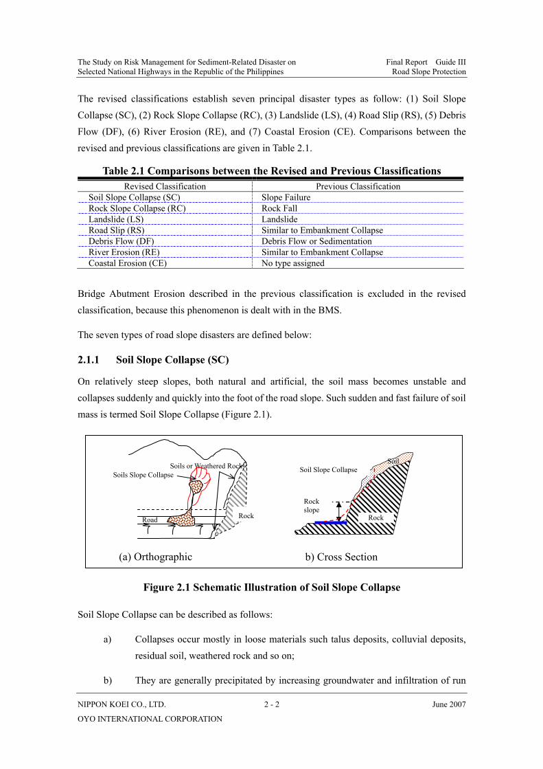
The revised classifications establish seven principal disaster types as follow: (1) Soil Slope Collapse (SC), (2) Rock Slope Collapse (RC), (3) Landslide (LS), (4) Road Slip (RS), (5) Debris Flow (DF), (6) River Erosion (RE), and (7) Coastal Erosion (CE). Comparisons between the revised and previous classifications are given in Table 2.1.
Table 2.1 Comparisons between the Revised and Previous Classifications Revised Classification Previous Classification
Soil Slope Collapse (SC) Slope Failure Rock Slope Collapse (RC) Rock Fall Landslide (LS) Landslide Road Slip (RS) Similar to Embankment Collapse Debris Flow (DF) Debris Flow or Sedimentation River Erosion (RE) Similar to Embankment Collapse Coastal Erosion (CE) No type assigned
Bridge Abutment Erosion described in the previous classification is excluded in the revised classification, because this phenomenon is dealt with in the BMS.
The seven types of road slope disasters are defined below:
2.1.1 Soil Slope Collapse (SC)
On relatively steep slopes, both natural and artificial, the soil mass becomes unstable and collapses suddenly and quickly into the foot of the road slope. Such sudden and fast failure of soil mass is termed Soil Slope Collapse (Figure 2.1).
Figure 2.1 Schematic Illustration of Soil Slope Collapse
Soil Slope Collapse can be described as follows:
a) Collapses occur mostly in loose materials such talus deposits, colluvial deposits, residual soil, weathered rock and so on;
b) They are generally precipitated by increasing groundwater and infiltration of run
Soils or Weathered Rocks
Road
Soils Slope Collapse
Rock
(a) Orthographic
Rock slope
Rock
Soil Soil Slope Collapse
b) Cross Section
The Study on Risk Management for Sediment-Related Disaster on Final Report Guide III Selected National Highways in the Republic of the Philippines Road Slope Protection
NIPPON KOEI CO., LTD. 2 - 3 June 2007
OYO INTERNATIONAL CORPORATION
off due to heavy rains or loosening of slopes by earthquakes;
c) The movement is very rapid, and the material is scattered and spread widely, the characteristics of which are quite different from landslides; and
d) Its size is generally small because only the area of loosened soil collapses.
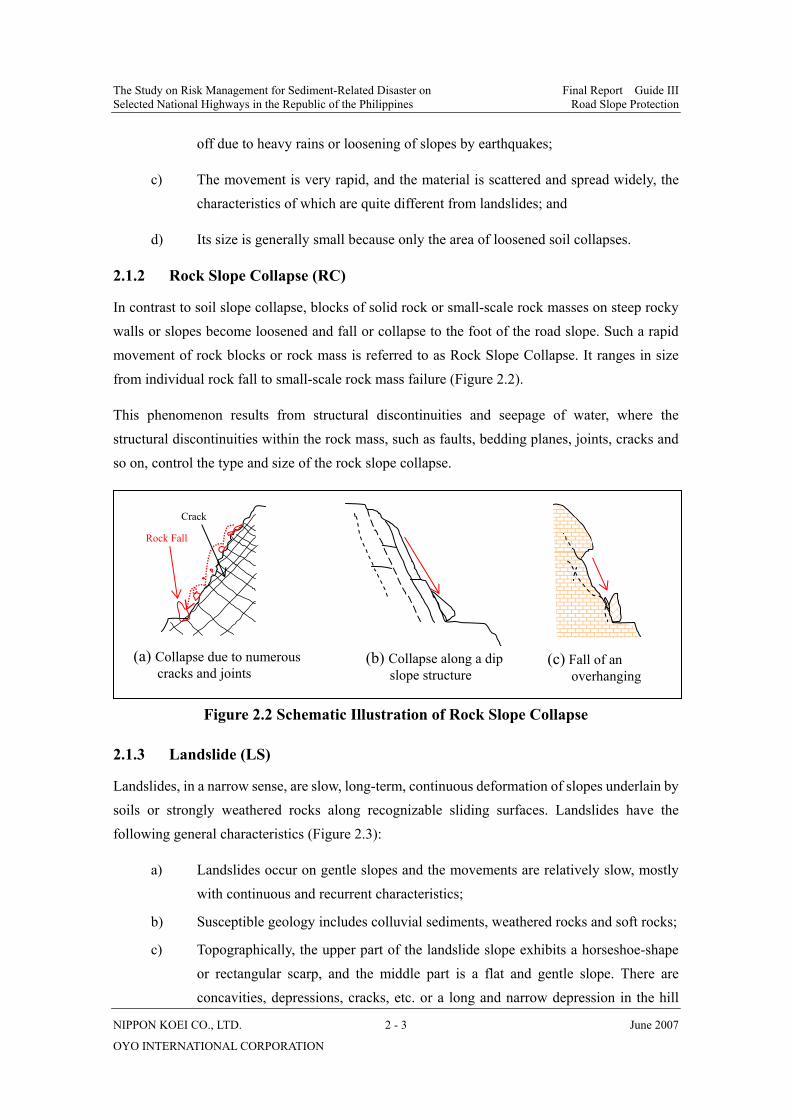
2.1.2 Rock Slope Collapse (RC)
In contrast to soil slope collapse, blocks of solid rock or small-scale rock masses on steep rocky walls or slopes become loosened and fall or collapse to the foot of the road slope. Such a rapid movement of rock blocks or rock mass is referred to as Rock Slope Collapse. It ranges in size from individual rock fall to small-scale rock mass failure (Figure 2.2).
This phenomenon results from structural discontinuities and seepage of water, where the structural discontinuities within the rock mass, such as faults, bedding planes, joints, cracks and so on, control the type and size of the rock slope collapse.
Figure 2.2 Schematic Illustration of Rock Slope Collapse
2.1.3 Landslide (LS)
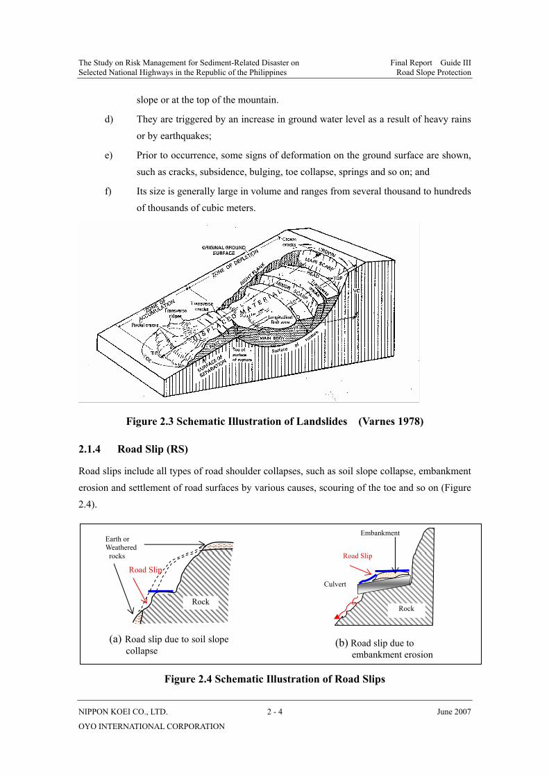
Landslides, in a narrow sense, are slow, long-term, continuous deformation of slopes underlain by soils or strongly weathered rocks along recognizable sliding surfaces. Landslides have the following general characteristics (Figure 2.3):
a) Landslides occur on gentle slopes and the movements are relatively slow, mostly with continuous and recurrent characteristics;
b) Susceptible geology includes colluvial sediments, weathered rocks and soft rocks;
c) Topographically, the upper part of the landslide slope exhibits a horseshoe-shape or rectangular scarp, and the middle part is a flat and gentle slope. There are concavities, depressions, cracks, etc. or a long and narrow depression in the hill
Rock Fall
Crack
(a) Collapse due to numerous cracks and joints
(b) Collapse along a dip slope structure
(c) Fall of an overhanging
The Study on Risk Management for Sediment-Related Disaster on Final Report Guide III Selected National Highways in the Republic of the Philippines Road Slope Protection
NIPPON KOEI CO., LTD. 2 - 4 June 2007
OYO INTERNATIONAL CORPORATION
slope or at the top of the mountain.
d) They are triggered by an increase in ground water level as a result of heavy rains or by earthquakes;
e) Prior to occurrence, some signs of deformation on the ground surface are shown, such as cracks, subsidence, bulging, toe collapse, springs and so on; and
f) Its size is generally large in volume and ranges from several thousand to hundreds of thousands of cubic meters.
Figure 2.3 Schematic Illustration of Landslides (Varnes 1978)
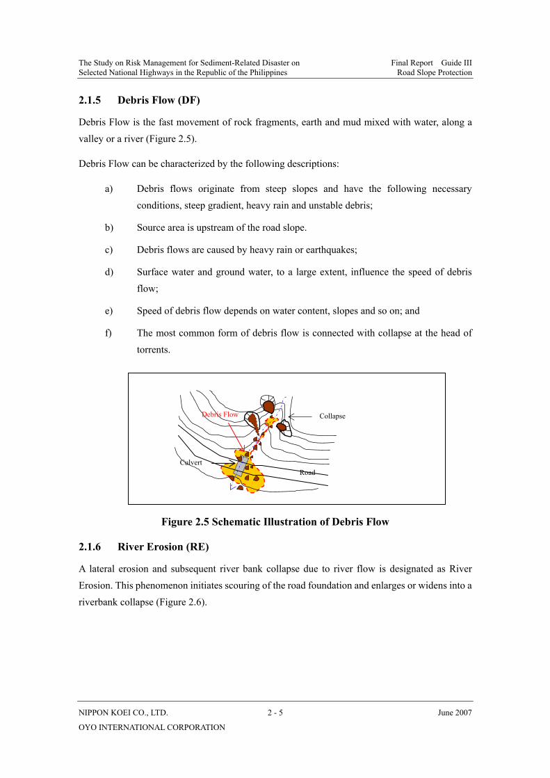
2.1.4 Road Slip (RS)
Road slips include all types of road shoulder collapses, such as soil slope collapse, embankment erosion and settlement of road surfaces by various causes, scouring of the toe and so on (Figure 2.4).
Figure 2.4 Schematic Illustration of Road Slips
Road Slip
Embankment
Rock
Culvert
Earth or Weathered rocks
Road Slip
Rock
(a) Road slip due to soil slope collapse
(b) Road slip due to embankment erosion
The Study on Risk Management for Sediment-Related Disaster on Final Report Guide III Selected National Highways in the Republic of the Philippines Road Slope Protection
NIPPON KOEI CO., LTD. 2 - 5 June 2007
OYO INTERNATIONAL CORPORATION
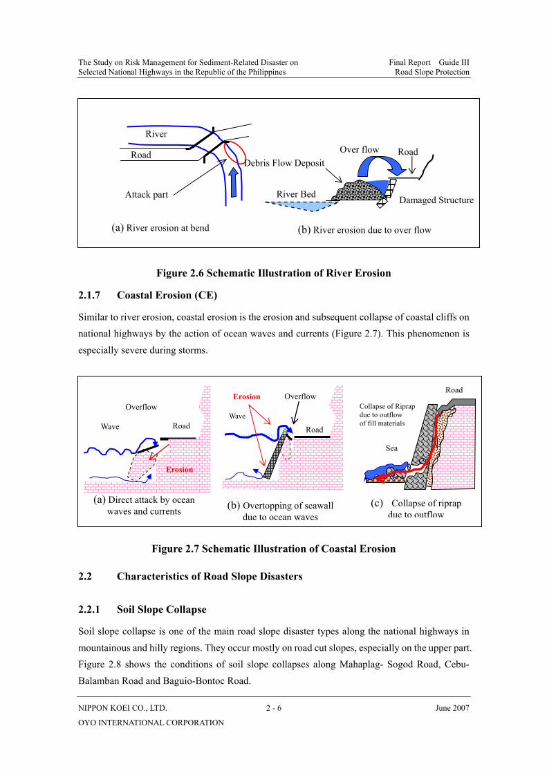
2.1.5 Debris Flow (DF)
Debris Flow is the fast movement of rock fragments, earth and mud mixed with water, along a valley or a river (Figure 2.5).
Debris Flow can be characterized by the following descriptions:
a) Debris flows originate from steep slopes and have the following necessary conditions, steep gradient, heavy rain and unstable debris;
b) Source area is upstream of the road slope.
c) Debris flows are caused by heavy rain or earthquakes;
d) Surface water and ground water, to a large extent, influence the speed of debris flow;
e) Speed of debris flow depends on water content, slopes and so on; and
f) The most common form of debris flow is connected with collapse at the head of torrents.
Figure 2.5 Schematic Illustration of Debris Flow
2.1.6 River Erosion (RE)
A lateral erosion and subsequent river bank collapse due to river flow is designated as River Erosion. This phenomenon initiates scouring of the road foundation and enlarges or widens into a riverbank collapse (Figure 2.6).
Road
Debris Flow
Culvert
Collapse
The Study on Risk Management for Sediment-Related Disaster on Final Report Guide III Selected National Highways in the Republic of the Philippines Road Slope Protection
NIPPON KOEI CO., LTD. 2 - 6 June 2007
OYO INTERNATIONAL CORPORATION
Figure 2.6 Schematic Illustration of River Erosion
2.1.7 Coastal Erosion (CE)
Similar to river erosion, coastal erosion is the erosion and subsequent collapse of coastal cliffs on national highways by the action of ocean waves and currents (Figure 2.7). This phenomenon is especially severe during storms.
Figure 2.7 Schematic Illustration of Coastal Erosion
2.2 Characteristics of Road Slope Disasters
2.2.1 Soil Slope Collapse
Soil slope collapse is one of the main road slope disaster types along the national highways in mountainous and hilly regions. They occur mostly on road cut slopes, especially on the upper part. Figure 2.8 shows the conditions of soil slope collapses along Mahaplag- Sogod Road, Cebu- Balamban Road and Baguio-Bontoc Road.
(a) River erosion at bend (b) River erosion due to over flow
Road
River
Attack part River Bed Damaged Structure
Debris Flow DepositOver flow Road
(a) Direct attack by ocean waves and currents (b) Overtopping of seawall
due to ocean waves
Road
Overflow
Erosion
Wave Road
Wave
Overflow Erosion Collapse of Riprap due to outflow of fill materials
Road
Sea
(c) Collapse of riprap due to outflow

The Study on Risk Management for Sediment-Related Disaster on Final Report Guide III Selected National Highways in the Republic of the Philippines Road Slope Protection
NIPPON KOEI CO., LTD. 2 - 7 June 2007
OYO INTERNATIONAL CORPORATION
The main features of soil slope collapse are summarized below:
a) Soil slope collapse frequently occurs on high cut slopes that are not protected by structures and have a slope gradient of over 50 degrees.
b) The geology of soil slope collapse is mainly loose and erodable sediments, such as residual soil, talus and topsoil.
c) The size of the soil slope collapse is relatively small, generally 10 to 20 m in width and length, 1 to 3 m in depth and less than 100m3 in volume. Soil slope collapses mostly concentrate on road slopes.
d) Soil slope collapse occurs suddenly and quickly during and after heavy rainfall. Besides loose soil structure, the occurrence trigger is erosion and the infiltration of rainfall, and earthquakes.
Figure 2.8 Soil Slope Collapses Occurring along the National Highways (a) Mahaplag-Sogod (km 1006+500), (b) Cebu-Balamban Road (Km 1007+100), (c) Baguio Bontoc Road (km 281+780), (d) Mahaplag -Sogod Road at Agas-agas.
Collapse
Residual Soil
(b)Collapse
Colluvial Deposit
(a)
Soil slope collapse
Bedrock
(c)
Soil slope
(d)Landslide

The Study on Risk Management for Sediment-Related Disaster on Final Report Guide III Selected National Highways in the Republic of the Philippines Road Slope Protection
NIPPON KOEI CO., LTD. 2 - 8 June 2007
OYO INTERNATIONAL CORPORATION
2.2.2 Rock Slope Collapse
Rock slope collapse occurs mainly on high cut slopes of highly fractured and jointed hard rocks, for example, Kennon Road, Marcos Highway, Lagawe-Banaue Road, Dalton Pass, Cebu-Balamban Transcentral Highway and Wright-Taft Road (Figure 2.9).
The main features of rock slope collapse are summarized below:
a) Rock slope collapse occurs chiefly on steep and high rock slopes, either cut or natural.
b) The majority of rock slope collapses are associated with highly fractured and jointed hard rocks, such as limestone, volcanic rock and phyllite.
c) Its size is generally less than 10 m3, occasionally over 100 m3 in volume.
Figure 2.9 Rock Slope Collapses Occurring along the National Highways (a) Kenon Road (Km 846+050), (b) and (d) Kennon Road, (c) Cebu- Balamban Transcentral Highway (Km 1027)
(d)(c)
(b)(a)

The Study on Risk Management for Sediment-Related Disaster on Final Report Guide III Selected National Highways in the Republic of the Philippines Road Slope Protection
NIPPON KOEI CO., LTD. 2 - 9 June 2007
OYO INTERNATIONAL CORPORATION
d) Failure modes are free fall, rolling down the slope or sliding along the slope.
e) The toe erosion and weathering of steep slopes, causing the gradual opening of tension cracks, is believed to be the mechanism by which most rock slope collapses are produced. Rock slope collapses occur mostly during intense rainfall and/or earthquakes, which appear to be the major triggers.
2.2.3 Landslides
Landslides are the most frequently observed road slope disasters along the national highways, especially on the Banaue-Lagawe and Mahaplag-Sogod Roads. These landslides severely threaten or damage the traffic function as shown in Figure 2.10.
Figure 2.10 Examples of Actual Landslides
(a) Landslide on the Banaue-Lagawe Road
(Km334+157)
Toe
Sliding mass
Sliding mass
Head
(b) Landslide on the Banaue-Lagawe Road
(Km301+200)
Road
Sliding mass
The Study on Risk Management for Sediment-Related Disaster on Final Report Guide III Selected National Highways in the Republic of the Philippines Road Slope Protection
NIPPON KOEI CO., LTD. 2 - 10 June 2007
OYO INTERNATIONAL CORPORATION
Besides the general features described above, landslides have the following characteristics:
a) Landslides occur chiefly on relatively gentle slopes, both natural and cut, of less than 30 degrees.
b) Landslides are concentrated mainly on soil slopes and soft rock slopes.
c) Landslides, in most cases, occur over relatively wide areas and are estimated to be 104 m3 to 106 m3 in volume.
d) They frequently occur or are activated during a rainfall. The infiltration of rainfall, causing a temporary rise in pore water pressure and the resulting reduction in shear resistance, is considered to contribute to occurrence of landslides.
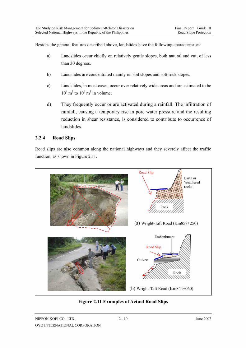
2.2.4 Road Slips
Road slips are also common along the national highways and they severely affect the traffic function, as shown in Figure 2.11.
Figure 2.11 Examples of Actual Road Slips
(a) Wright-Taft Road (Km858+250)
Road Slip Earth or Weathered rocks
Rock
(b) Wright-Taft Road (Km844+060)
Road Slip
Embankment
Rock
Culvert

The Study on Risk Management for Sediment-Related Disaster on Final Report Guide III Selected National Highways in the Republic of the Philippines Road Slope Protection
NIPPON KOEI CO., LTD. 2 - 11 June 2007
OYO INTERNATIONAL CORPORATION
The main features of road slips are summarized below:
a) Road slips have the following three failure modes: 1) Collapse of the valley side slope, 2) Scouring of the valley side slope due to inappropriate drainage, and 3) Road body settlement.
b) Road slips may occur abruptly after heavy rainfall, but such indications as local deformation or settlement of the road shoulder are observable prior to complete collapse.
c) Road slips, in most cases, are less than 50m in width and occur on steep slopes on the valley side.
d) Road slips mostly occur in places where surface water concentrates during heavy rainfall, in some cases this is due to inappropriate design or construction of the wall foundation, subsurface drainage (leakage of water), insufficient road compaction, or insufficient drainage facilities.
2.2.5 Debris Flow
Debris flows are infrequent along the national highways. Some have occurred in hilly regions as shown in Figure 2.12.
Figure 2.12 Example of Debris Flow on Dalton Pass in Nueva Viscaya
The trace of debris deposited by a debris flow is observable on a stone masonry wall and check dam.

The Study on Risk Management for Sediment-Related Disaster on Final Report Guide III Selected National Highways in the Republic of the Philippines Road Slope Protection
NIPPON KOEI CO., LTD. 2 - 12 June 2007
OYO INTERNATIONAL CORPORATION
2.2.6 River Erosion
River erosions occur on embankments or natural bank slopes along the national highways (Figure 2.13). The main features of river erosions are summarized below:
a) River erosions are concentrated on outer bends, especially where the river meanders through the slope.
b) The occurrence of river erosions is due firstly to bank erosion, secondly to riverbed erosion, and thirdly to the change of river course towards the bank and the rising of the river water level as a result of the accumulation of debris flow sediments.
c) River erosions are of a smaller scale, generally less than 50 meters in length.
2.2.7 Coastal Erosion
Coastal erosions are observable, especially along the Ginalitan-Alegria Road between 143km and 180km, as shown in Figure 2.13.
The main features of coastal erosions are summarized below:
a) Coastal erosions initiate scouring of the foundation or out flowing of backfill material by the action of ocean waves and currents, consequently leading to road slip, road body settlement, or wall collapse.
b) The phenomenon is associated mainly with soil slopes, strongly weathered rocks and highly fractured limestone.
Kennon Road 215km+132 Mahaplag-Sogod Section
Figure 2.13 Examples of River Erosion
The Study on Risk Management for Sediment-Related Disaster on Final Report Guide III Selected National Highways in the Republic of the Philippines Road Slope Protection
NIPPON KOEI CO., LTD. 2 - 13 June 2007
OYO INTERNATIONAL CORPORATION
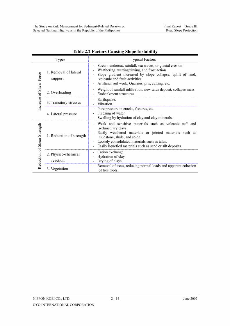
2.3 Main Factors Causing Road Slope Disasters
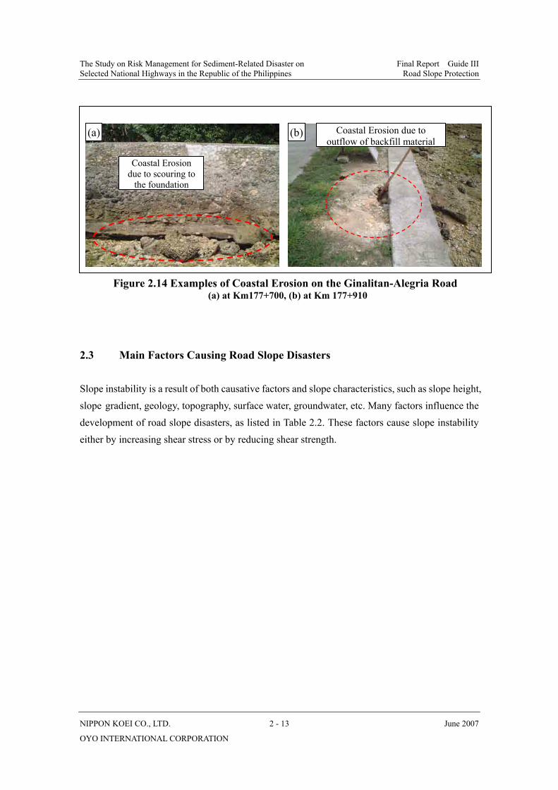
Slope instability is a result of both causative factors and slope characteristics, such as slope height, slope gradient, geology, topography, surface water, groundwater, etc. Many factors influence the development of road slope disasters, as listed in Table 2.2. These factors cause slope instability either by increasing shear stress or by reducing shear strength.
Figure 2.14 Examples of Coastal Erosion on the Ginalitan-Alegria Road (a) at Km177+700, (b) at Km 177+910
Coastal Erosion due to scouring to
the foundation
Coastal Erosion due to outflow of backfill material
(a) (b)
The Study on Risk Management for Sediment-Related Disaster on Final Report Guide III Selected National Highways in the Republic of the Philippines Road Slope Protection
NIPPON KOEI CO., LTD. 2 - 14 June 2007
OYO INTERNATIONAL CORPORATION
Table 2.2 Factors Causing Slope Instability
Types Typical Factors
1. Removal of lateral support
- Stream undercut, rainfall, sea waves, or glacial erosion - Weathering, wetting/drying, and frost action - Slope gradient increased by slope collapse, uplift of land,
volcanic and fault activities - Artificial soil work: Quarries, pits, cutting, etc.
2. Overloading - Weight of rainfall infiltration, new talus deposit, collapse mass.- Embankment structures.
3. Transitory stresses - Earthquake. - Vibration.
Incr
ease
of S
hear
For
ce
4. Lateral pressure - Pore pressure in cracks, fissures, etc. - Freezing of water. - Swelling by hydration of clay and clay minerals.
1. Reduction of strength
- Weak and sensitive materials such as volcanic tuff and sedimentary clays.
- Easily weathered materials or jointed materials such as mudstone, shale, and so on.
- Loosely consolidated materials such as talus. - Easily liquefied materials such as sand or silt deposits.
2. Physico-chemical reaction
- Cation exchange. - Hydration of clay. - Drying of clays.
Red
uctio
n of
She
ar S
treng
th
3. Vegetation - Removal of trees, reducing normal loads and apparent cohesion
of tree roots.
The Study on Risk Management for Sediment-Related Disaster on Draft Final Report Volume III Selected National Highways in the Republic of the Philippines Road Slope Protection
NIPPON KOEI CO., LTD. 3 - 1 June 2007
OYO INTERNATIONAL CORPORATION
CHAPTER 3
COUNTERMEASURES AGAINST SOIL SLOPE COLLAPSE
3.1 General
Soil slope collapse, as defined in Chapter 2, is failure of a soil slope. They tend to occur suddenly on relatively steep slopes. This chapter provides general policy and basic procedures for the stabilization of soil slopes, mitigation of soil slope collapse, and design considerations for main countermeasures against soil slope collapse.
In addition, the design procedures and considerations of countermeasures against landslides given in Chapter 5 of this Guide III may also be applied to the stabilization of soil slope collapses.
3.2 General Policy for Stabilization of Soil Slopes
Soil slope collapses, especially soil cut slope collapses, are common along the national highways. Frequent occurrences of soil slope collapse are due mainly to inappropriate design and construction of cut slopes and slope protection works in addition to steep topography, fragile geology, heavy rainfall and frequent earthquakes.
Of all of these causes, the greatest cause of soil slope collapses is the action of water. The collapse of soil slope induced by water can be subdivided roughly into two types: surface erosion due to slope surface water and collapse due to the increase in pore water pressure or the decrease in shearing strength of soils forming the slope by scouring and water seepage. It is thus extremely important to take appropriate measures against water to secure slope stability.
In order to prevent the road slope disasters related to soil slope collapse, the general policies for the stabilization of soil slopes are structured in consideration of (a) degree of safety, (b) construction cost, (c) appearance, and 4) construction workability, and are as follows:
a) Design of standard slope (cut and fill);
b) Drainage (surface water ); and
c) Slope protection (structural).

The Study on Risk Management for Sediment-Related Disaster on Draft Final Report Volume III Selected National Highways in the Republic of the Philippines Road Slope Protection
NIPPON KOEI CO., LTD. 3 - 2 June 2007
OYO INTERNATIONAL CORPORATION
3.3 Design of Standard Slope (Cut Slope)
This section focuses on the design of standard cut slopes because soil slope collapses frequently occur in cut slopes along the national highways, and, compared to cut slopes, it is easier to determine the proper design section of fill slopes, which are generally formed by homogeneous fill materials.
3.3.1 Standard Gradients of Cut Slopes
A stable cut slope is generally designed according to the standard values of the gradient of slopes, as listed in Table 3.1, due to the following:
a) Natural ground is extremely complicated and not uniform in its properties;
b) Cut slopes tend to gradually become unstable over time after completion of work; and
c) It is difficult to determine the proper design section of cut slopes by stability calculations.
Table 3.1 Geometric Standards for Cut Slopes
Character of soil or bedrock Cut slope height (m)
Gradient (i=V:H)
Hard rock 1:0.3 ~ 1:0.8 Soft rock 1:0.5 ~ 1:1.2
Sand Sand that is not solid or dense and has poor grade distribution.
1:1.5 ~
Less than 5 m 1:0.8 ~ 1:1.0 Soils that are dense and solid. 5~10 m 1:1.0 ~ 1:1.2
Less than 5 m 1:1.0 ~ 1:1.2 Sandy soil Soils that are not dense and solid. 5~10 m 1:1.2 ~ 1:1.5
Less than 10 m 1:0.8 ~ 1:1.0 Soils that are dense and solid or of good grade distribution. 10~15 m 1:1.0 ~ 1:1.2
Less than 10 m 1:1.0 ~ 1:1.2
Sandy soil mixed with gravel or rock
Soils that are not dense or solid or are of bad grade distribution. 10~15 m 1:1.2 ~ 1:1.5
Cohesive soil Less than 10 m 1:0.8 ~ 1:1.2
Less than 5 m 1:1.0 ~ 1:1.2 Cohesive soil mixed with rock or cobble stones
5~10 m 1:1.2 ~ 1:1.5
Notes: (1) Silt is included in the category of cohesive soil. (2) Individual consideration is given to soils not indicated in the above table. (3) When a single gradient can not opted for because of the soil composition or other reasons,
the cut slope height and gradient are determined on the basis of the following considerations.
Source: Modified from Reference No.1 Highway Earthwork Series, MANUAL FOR RETAINING WALLS, Published by Japan Road Association, March 1999.

The Study on Risk Management for Sediment-Related Disaster on Draft Final Report Volume III Selected National Highways in the Republic of the Philippines Road Slope Protection
NIPPON KOEI CO., LTD. 3 - 3 June 2007
OYO INTERNATIONAL CORPORATION
• The gradient does not include a berm.
• The cut slope height vis-à-vis the gradient means the total cut slope height including all
the cut slopes above the cut slope in question.
The standard values of the gradient of slopes, as shown in Table 3.1 have been empirically determined on the basis of geological conditions and at the standard values, cut slopes remain stable over the long-term with simple slope protection works such as vegetation.
As shown in Table 3.1, the gradient of cut slopes varies depending on the geology of the cut slope. Where the geology and soil of a cut slope varies considerably and is complicated, a single gradient of cut slope suited to weaker soil is used even though this is somewhat uneconomical. Figure 3.1 gives a schematic diagram of a cut slope relating to different geology.
^
Figure 3.1 Conceptual Illustration of a Cut Slope
3.3.2 Berms of Cut Slopes
On the cut slopes, berms 1.0 to 2.0 m wide are generally provided for every 5.0 to 7.0 m in height for the following purposes:
Hard rock
Soft rock
Colluvial deposits
1:1
.0
1:1.2
1:1.2
Road
H = 5 to 7 m
H < 30 m
1:0
.3~
1:0.
8 1:.0.5~
1:1.2
1:.0.8~1:1.5
1:.0.8~1:1.5
ha: Cut slope height for slope surface a
hb: Cut slope height for slope surface b equals the height of a plus the height of b
a
b
ha
hb
The Study on Risk Management for Sediment-Related Disaster on Draft Final Report Volume III Selected National Highways in the Republic of the Philippines Road Slope Protection
NIPPON KOEI CO., LTD. 3 - 4 June 2007
OYO INTERNATIONAL CORPORATION
a) To reduce speed of the surface water flow on the cut slopes, thereby decreasing scouring force on the cut slopes;
b) To provide a place for the installation of drainage ditches; and
c) To be used as sidewalk for inspection or as scaffolding for repair works.
A wider berm is recommended where the slope is long and large or where rock fall protection fences are to be installed.
3.3.3 Survey Checkpoints for Cut Slopes
Careful surveys on the stability of back slopes should be conducted prior to cutting. When the potentially unstable areas above the cut sites are large, cutting should be abandoned.
The main checkpoints of the surveys for cut slopes are as follows:
a) Stability of cut slope;
b) Average gradient of adjacent natural slopes;
c) Danger of landslide, soil slope collapse, or rock fall from the top of cut slopes;
d) Change of groundwater level in adjacent areas due to excavation; and
e) Geotechnical properties of the ground to be excavated.
A survey plan should be made for reviewing and determining measures for each item listed above.
3.3.4 Cut Requiring Caution
In designing cut slopes, the following geological conditions are to be considered with the utmost care:
a) Colluvial deposit slopes. Colluvial deposits such as talus or trace of volcanic mudflow have a low solidification and, usually form a slope with a critical angle of stability. When excavated, such cut slopes will become unstable. For this reason, a wide step near the boundary line between bedrock and the upper colluvial deposit should be planned (Figure 3.2).
b) Erodible sandy soil. Sandy soils such as weathered granite and terrace gravel layers are easily eroded by surface water, resulting in small shallow collapses.
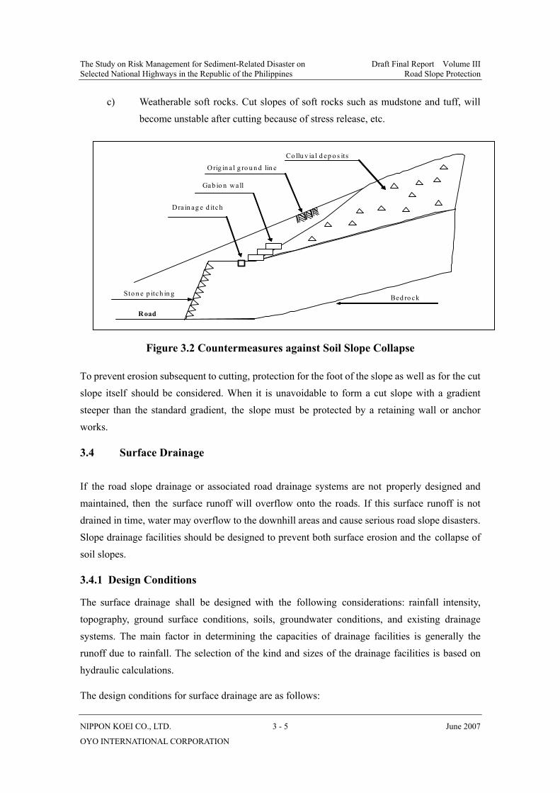
The Study on Risk Management for Sediment-Related Disaster on Draft Final Report Volume III Selected National Highways in the Republic of the Philippines Road Slope Protection
NIPPON KOEI CO., LTD. 3 - 5 June 2007
OYO INTERNATIONAL CORPORATION
c) Weatherable soft rocks. Cut slopes of soft rocks such as mudstone and tuff, will become unstable after cutting because of stress release, etc.
Figure 3.2 Countermeasures against Soil Slope Collapse
To prevent erosion subsequent to cutting, protection for the foot of the slope as well as for the cut slope itself should be considered. When it is unavoidable to form a cut slope with a gradient steeper than the standard gradient, the slope must be protected by a retaining wall or anchor works.
3.4 Surface Drainage
If the road slope drainage or associated road drainage systems are not properly designed and maintained, then the surface runoff will overflow onto the roads. If this surface runoff is not drained in time, water may overflow to the downhill areas and cause serious road slope disasters. Slope drainage facilities should be designed to prevent both surface erosion and the collapse of soil slopes.
3.4.1 Design Conditions
The surface drainage shall be designed with the following considerations: rainfall intensity, topography, ground surface conditions, soils, groundwater conditions, and existing drainage systems. The main factor in determining the capacities of drainage facilities is generally the runoff due to rainfall. The selection of the kind and sizes of the drainage facilities is based on hydraulic calculations.
The design conditions for surface drainage are as follows:
Road
Bed ro ck
Orig in a l g ro u n d lin e
Sto n e p itch in g
Gab io n wa ll
Dra in ag e d itch
Co llu v ia l d ep o s its
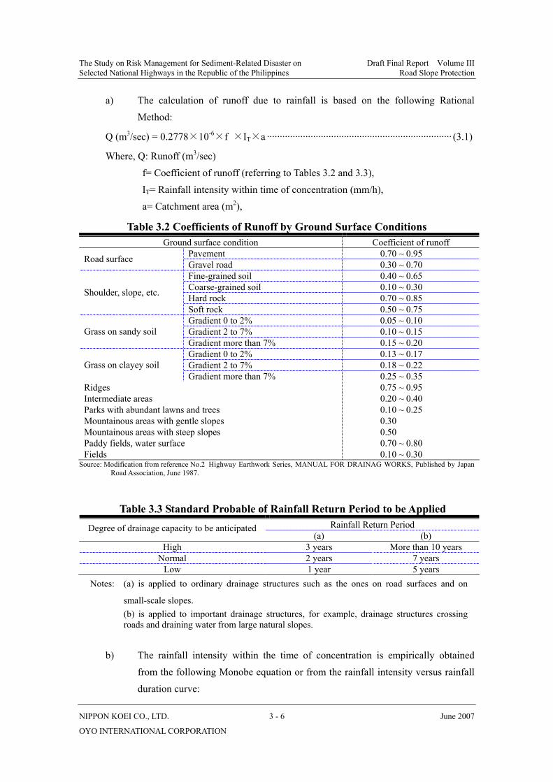
The Study on Risk Management for Sediment-Related Disaster on Draft Final Report Volume III Selected National Highways in the Republic of the Philippines Road Slope Protection
NIPPON KOEI CO., LTD. 3 - 6 June 2007
OYO INTERNATIONAL CORPORATION
a) The calculation of runoff due to rainfall is based on the following Rational Method:
Q (m3/sec) = 0.2778×10⁻⁶×f ×IT×a ········································································ (3.1)
Where, Q: Runoff (m3/sec) f= Coefficient of runoff (referring to Tables 3.2 and 3.3), IT= Rainfall intensity within time of concentration (mm/h), a= Catchment area (m2),
Table 3.2 Coefficients of Runoff by Ground Surface Conditions Ground surface condition Coefficient of runoff
Pavement 0.70 ~ 0.95 Road surface Gravel road 0.30 ~ 0.70 Fine-grained soil 0.40 ~ 0.65 Coarse-grained soil 0.10 ~ 0.30 Hard rock 0.70 ~ 0.85 Shoulder, slope, etc.
Soft rock 0.50 ~ 0.75 Gradient 0 to 2% 0.05 ~ 0.10 Gradient 2 to 7% 0.10 ~ 0.15 Grass on sandy soil Gradient more than 7% 0.15 ~ 0.20 Gradient 0 to 2% 0.13 ~ 0.17 Gradient 2 to 7% 0.18 ~ 0.22 Grass on clayey soil Gradient more than 7% 0.25 ~ 0.35
Ridges 0.75 ~ 0.95 Intermediate areas 0.20 ~ 0.40 Parks with abundant lawns and trees 0.10 ~ 0.25 Mountainous areas with gentle slopes 0.30 Mountainous areas with steep slopes 0.50 Paddy fields, water surface 0.70 ~ 0.80 Fields 0.10 ~ 0.30
Source: Modification from reference No.2 Highway Earthwork Series, MANUAL FOR DRAINAG WORKS, Published by Japan Road Association, June 1987.
Table 3.3 Standard Probable of Rainfall Return Period to be Applied Rainfall Return Period Degree of drainage capacity to be anticipated
(a) (b) High 3 years More than 10 years
Normal 2 years 7 years Low 1 year 5 years
Notes: (a) is applied to ordinary drainage structures such as the ones on road surfaces and on
small-scale slopes. (b) is applied to important drainage structures, for example, drainage structures crossing
roads and draining water from large natural slopes.
b) The rainfall intensity within the time of concentration is empirically obtained from the following Monobe equation or from the rainfall intensity versus rainfall duration curve:
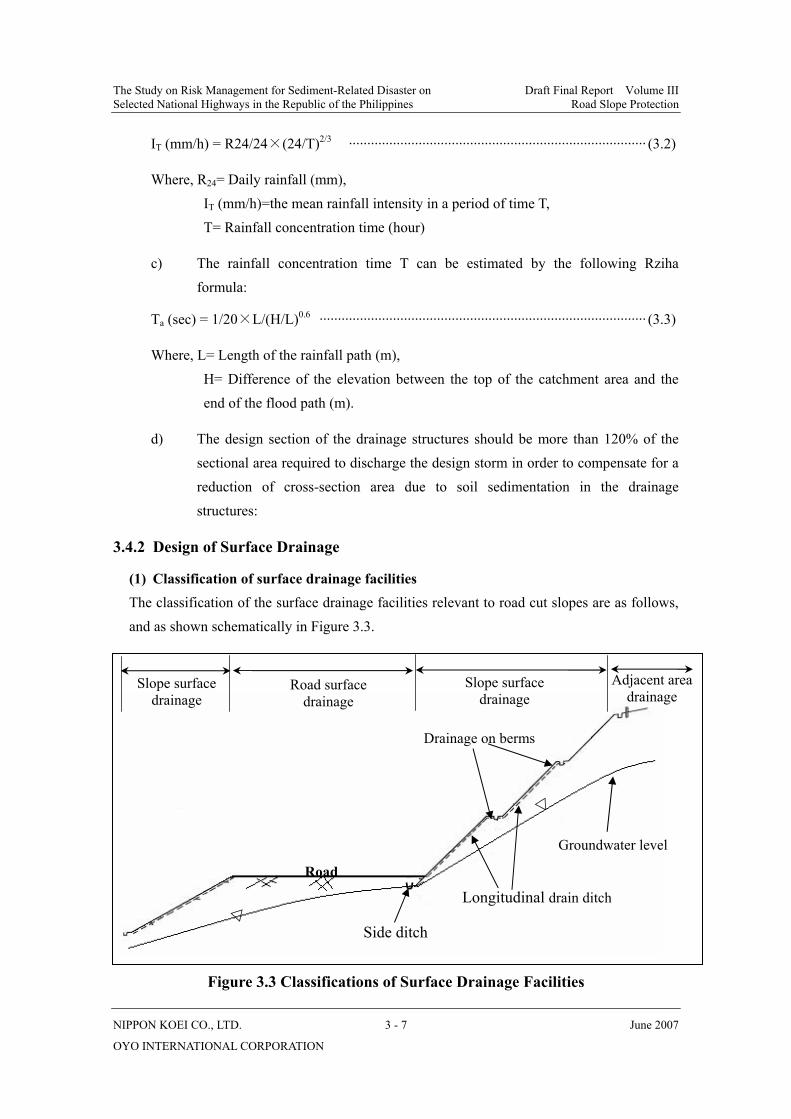
The Study on Risk Management for Sediment-Related Disaster on Draft Final Report Volume III Selected National Highways in the Republic of the Philippines Road Slope Protection
NIPPON KOEI CO., LTD. 3 - 7 June 2007
OYO INTERNATIONAL CORPORATION
IT (mm/h) = R24/24×(24/T)2/3 ················································································· (3.2)
Where, R24= Daily rainfall (mm), IT (mm/h)=the mean rainfall intensity in a period of time T, T= Rainfall concentration time (hour)
c) The rainfall concentration time T can be estimated by the following Rziha formula:
Ta (sec) = 1/20×L/(H/L)0.6 ························································································· (3.3)
Where, L= Length of the rainfall path (m), H= Difference of the elevation between the top of the catchment area and the end of the flood path (m).
d) The design section of the drainage structures should be more than 120% of the sectional area required to discharge the design storm in order to compensate for a reduction of cross-section area due to soil sedimentation in the drainage structures:
3.4.2 Design of Surface Drainage
(1) Classification of surface drainage facilities The classification of the surface drainage facilities relevant to road cut slopes are as follows, and as shown schematically in Figure 3.3.
Figure 3.3 Classifications of Surface Drainage Facilities
▽
▽
Road
Road surface drainage
Slope surface drainage
Slope surface drainage
Adjacent area drainage
Drainage on berms
Longitudinal drain ditch
Groundwater level
Side ditch

The Study on Risk Management for Sediment-Related Disaster on Draft Final Report Volume III Selected National Highways in the Republic of the Philippines Road Slope Protection
NIPPON KOEI CO., LTD. 3 - 8 June 2007
OYO INTERNATIONAL CORPORATION
(2) Horizontal drainage ditches Horizontal drainage ditches or berm drainage ditches shall be designed to prevent slope surface erosion caused by rainfall or spring water.
The drainage ditches shall be constructed using soil cement mixtures, reinforced concrete U-shaped gutters or be of the unsupported types. Figure 3.4 gives the structural image of a horizontal or berm drainage ditch.
These ditches shall be installed close to the toe of the slope to prevent the flow of water at the back or sides of the ditch.When berm drains are provided, the width of the berm should be greater than 1.5m.
Figure 3.4 Details of Berm Drainage Ditches Source: Reference No.8 Technical Standards and Guidelines for Planning and Design, Volume IV, NATURAL SLOPE FAILURE
COUNTERMEASURES, Project for the Enhancement of Capability in Flood Control and Sabo Engineering of DPWH, March 2002.
(3) Longitudinal drainage ditches Longitudinal drainage ditches shall be designed to guide the water from a ditch at the top of a slope or berm to a proper channel at the toe of the slope.
The longitudinal drainage ditches are generally constructed using reinforced concrete U-shaped gutters, reinforced concrete pipes, or are stone-pitched (ladder type) channels. An example is shown in Figure 3.5.
At places where the direction of the flow changes drastically or where the longitudinal drainage ditch meets other waterways, a collecting basin with covers and simple sediment pit should be installed to reduce the energy of the running water. In principle, longitudinal drainage ditches are installed under the following conditions (Figure 3.6);
a) Slopes are wider than 100 meters; and
About 5%About 5%
Soil-Cement mixtureor Concrete
Soil-Cement Mixtureor Concrete
Reinforced ConcreteU-Shaped Gutter
More than 1.5 m
More than 1.5 m

The Study on Risk Management for Sediment-Related Disaster on Draft Final Report Volume III Selected National Highways in the Republic of the Philippines Road Slope Protection
NIPPON KOEI CO., LTD. 3 - 9 June 2007
OYO INTERNATIONAL CORPORATION
b) On valley-shaped slope, rainfall water is expected to flow in from the upper slope.
Figure 3.5 Structural Image of Drainage Ditch Source: Reference No.8 Technical Standards and Guidelines for Planning and Design, Volume IV, NATURAL SLOPE FAILURE
COUNTERMEASURES, Project for the Enhancement of Capability in Flood Control and Sabo Engineering of DPWH, March 2002.
Figure 3.6 Example of Drainage Ditch Layout
(4) Drainage ditches at the top of a slope Drainage ditches for the top of the slope shall be installed along the top of the slope to prevent flow of surface run-off from adjacent areas onto the slope.
The size of the ditch along the top of the slope shall be determined according to the amount of
Cover
Anti-slipconcrete
Concrete U-shapedgutter with socket Foundation Material
Reinforced concreteU-shaped gutter
Sodding or stonePitching
SoilSoft RockHard Rock
0.5:10.3:10.2:1
3:1
1.5:1 - 1.8:1
Ditch
Catch Basin
Cover
3:1
Backfilled withSoil-cementmixture or thelike
80
5015 15 93
33
3924
524
(b)(a)90
5015 155 5
8060
10
1015
24
510
H
H:1
H
Cut slope
Fill slope
Longitudinal drainage ditch
Road
Berm drainage
Crest drain ditch
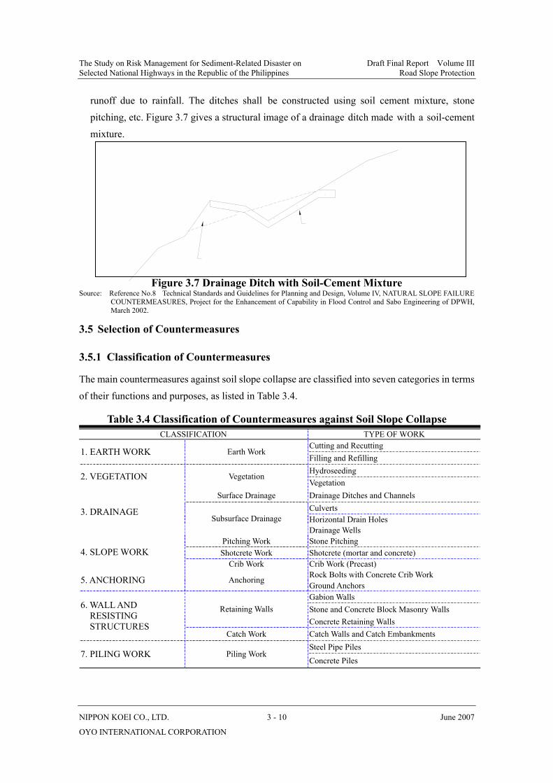
The Study on Risk Management for Sediment-Related Disaster on Draft Final Report Volume III Selected National Highways in the Republic of the Philippines Road Slope Protection
NIPPON KOEI CO., LTD. 3 - 10 June 2007
OYO INTERNATIONAL CORPORATION
runoff due to rainfall. The ditches shall be constructed using soil cement mixture, stone pitching, etc. Figure 3.7 gives a structural image of a drainage ditch made with a soil-cement mixture.
Figure 3.7 Drainage Ditch with Soil-Cement Mixture Source: Reference No.8 Technical Standards and Guidelines for Planning and Design, Volume IV, NATURAL SLOPE FAILURE
COUNTERMEASURES, Project for the Enhancement of Capability in Flood Control and Sabo Engineering of DPWH, March 2002.
3.5 Selection of Countermeasures
3.5.1 Classification of Countermeasures
The main countermeasures against soil slope collapse are classified into seven categories in terms of their functions and purposes, as listed in Table 3.4.
Table 3.4 Classification of Countermeasures against Soil Slope Collapse CLASSIFICATION TYPE OF WORK
Cutting and Recutting 1. EARTH WORK Earth Work
Filling and Refilling Hydroseeding 2. VEGETATION Vegetation Vegetation
Surface Drainage Drainage Ditches and Channels Culverts Horizontal Drain Holes
3. DRAINAGE Subsurface Drainage
Drainage Wells Pitching Work Stone Pitching Shotcrete Work Shotcrete (mortar and concrete) 4. SLOPE WORK
Crib Work Crib Work (Precast) Rock Bolts with Concrete Crib Work 5. ANCHORING Anchoring Ground Anchors Gabion Walls Stone and Concrete Block Masonry Walls Retaining Walls Concrete Retaining Walls
6. WALL AND RESISTING STRUCTURES
Catch Work Catch Walls and Catch Embankments Steel Pipe Piles
7. PILING WORK Piling Work Concrete Piles
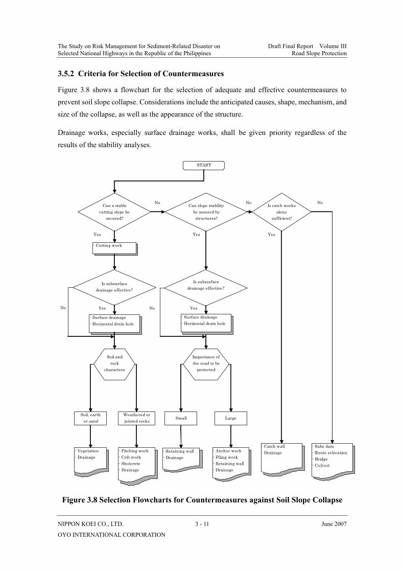
The Study on Risk Management for Sediment-Related Disaster on Draft Final Report Volume III Selected National Highways in the Republic of the Philippines Road Slope Protection
NIPPON KOEI CO., LTD. 3 - 11 June 2007
OYO INTERNATIONAL CORPORATION
3.5.2 Criteria for Selection of Countermeasures
Figure 3.8 shows a flowchart for the selection of adequate and effective countermeasures to prevent soil slope collapse. Considerations include the anticipated causes, shape, mechanism, and size of the collapse, as well as the appearance of the structure.
Drainage works, especially surface drainage works, shall be given priority regardless of the results of the stability analyses.
Figure 3.8 Selection Flowcharts for Countermeasures against Soil Slope Collapse
START
Can a stablecutting slope be
secured?
Can slope stabilitybe assured bystructures?
Is catch worksalone
sufficient?
No
- Surface drainage- Horizontal drain hole
Is subsurfacedrainage effective?
Yes
Weathered orjointed rocks
Small Large
- Vegetation- Drainage
- Pitching work- Crib work- Shotcrete- Drainage
Soil, earthor sand
- Retaining wall- Drainage
- Catch wall- Drainage- Anchor work
- Piling work- Retaining wall- Drainage
- Sabo dam- Route relocation- Bridge- Culvert
Importance ofthe road to be
protected
Soil androck
characters
Is subsurfacedrainage effective?
No
- Cutting work
- Surface drainage- Horizontal drain hole
No
YesYes
YesNoYesNo
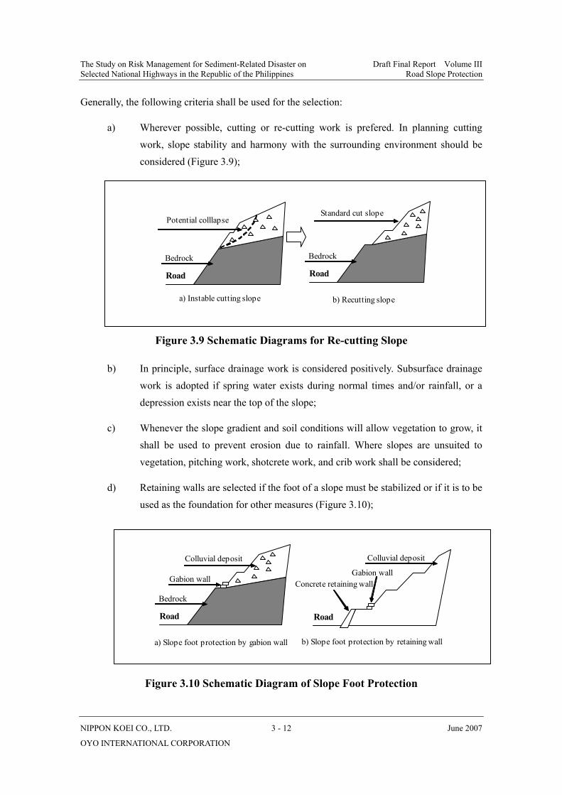
The Study on Risk Management for Sediment-Related Disaster on Draft Final Report Volume III Selected National Highways in the Republic of the Philippines Road Slope Protection
NIPPON KOEI CO., LTD. 3 - 12 June 2007
OYO INTERNATIONAL CORPORATION
Generally, the following criteria shall be used for the selection:
a) Wherever possible, cutting or re-cutting work is prefered. In planning cutting work, slope stability and harmony with the surrounding environment should be considered (Figure 3.9);
Figure 3.9 Schematic Diagrams for Re-cutting Slope
b) In principle, surface drainage work is considered positively. Subsurface drainage work is adopted if spring water exists during normal times and/or rainfall, or a depression exists near the top of the slope;
c) Whenever the slope gradient and soil conditions will allow vegetation to grow, it shall be used to prevent erosion due to rainfall. Where slopes are unsuited to vegetation, pitching work, shotcrete work, and crib work shall be considered;
d) Retaining walls are selected if the foot of a slope must be stabilized or if it is to be used as the foundation for other measures (Figure 3.10);
Figure 3.10 Schematic Diagram of Slope Foot Protection
Potential colllapse
Road
Bedrock
Standard cut slope
Road
Bedrock
a) Instable cutting slope b) Recutting slope
a) Slope foot protection by gabion wall
Road
Bedrock
Colluvial deposit
Gabion wall
Road
Colluvial deposit
Gabion wallConcrete retaining wall
b) Slope foot protection by retaining wall

The Study on Risk Management for Sediment-Related Disaster on Draft Final Report Volume III Selected National Highways in the Republic of the Philippines Road Slope Protection
NIPPON KOEI CO., LTD. 3 - 13 June 2007
OYO INTERNATIONAL CORPORATION
e) Even though costly, anchoring or piling should be planned if other methods are not expected to control soil slope collapse (Figure 3.11);
Figure 3.11 Schematic Diagrams of Anchor and Pile Works
f) When a potential soil slope collapse is large, avoiding the unstable area by using an alternate route or by the construction of a bridge or similar structure shall be considered.
3.6 Design of Main Countermeasures
3.6.1 Vegetation
A dense vegetation cover can prevent the formation of unstable debris on bare hillsides such as collapsed surfaces and bare slopes. This method is one of the most important countermeasures and is normally cost-effective.
(1) Purposes The main objectives of vegetation are to (a) reduce surface erosion caused by running water and rainfall; (b) reduce infiltration from rainfall; (c) bind subsurface soil with root systems; and (d) improve the landscape of the cut slope.
(2) Design Considerations In principle, slope vegetation is employed when the slope is to be stabilized by installation of other countermeasures.
In selecting the type of vegetation to be planted, careful attention is to be paid to rainfall, plant growth conditions, soil properties of the slope, and the timing of construction as well as the area of the protection works. Table 3.5 gives the general selection criteria for the various vegetation placement methods.
a) Slope stabilization by anchor b) Slope stabilization by pile
Road
Anchor work
Potential large soil collapse
RoadSteel pile work
Potential large soil collapse
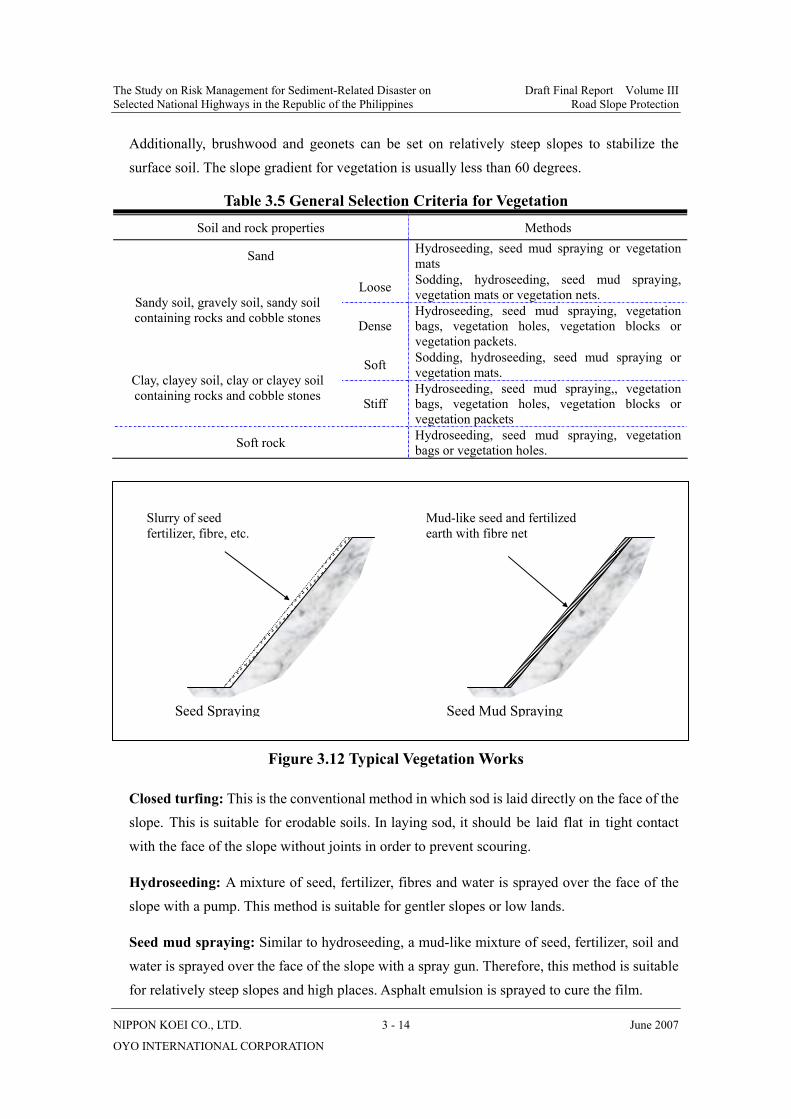
The Study on Risk Management for Sediment-Related Disaster on Draft Final Report Volume III Selected National Highways in the Republic of the Philippines Road Slope Protection
NIPPON KOEI CO., LTD. 3 - 14 June 2007
OYO INTERNATIONAL CORPORATION
Additionally, brushwood and geonets can be set on relatively steep slopes to stabilize the surface soil. The slope gradient for vegetation is usually less than 60 degrees.
Table 3.5 General Selection Criteria for Vegetation
Soil and rock properties Methods
Sand Hydroseeding, seed mud spraying or vegetation mats
Loose Sodding, hydroseeding, seed mud spraying, vegetation mats or vegetation nets. Sandy soil, gravely soil, sandy soil
containing rocks and cobble stones Dense Hydroseeding, seed mud spraying, vegetation bags, vegetation holes, vegetation blocks or vegetation packets.
Soft Sodding, hydroseeding, seed mud spraying or vegetation mats. Clay, clayey soil, clay or clayey soil
containing rocks and cobble stones Stiff Hydroseeding, seed mud spraying,, vegetation bags, vegetation holes, vegetation blocks or vegetation packets
Soft rock Hydroseeding, seed mud spraying, vegetation bags or vegetation holes.
Figure 3.12 Typical Vegetation Works
Closed turfing: This is the conventional method in which sod is laid directly on the face of the slope. This is suitable for erodable soils. In laying sod, it should be laid flat in tight contact with the face of the slope without joints in order to prevent scouring.
Hydroseeding: A mixture of seed, fertilizer, fibres and water is sprayed over the face of the slope with a pump. This method is suitable for gentler slopes or low lands.
Seed mud spraying: Similar to hydroseeding, a mud-like mixture of seed, fertilizer, soil and water is sprayed over the face of the slope with a spray gun. Therefore, this method is suitable for relatively steep slopes and high places. Asphalt emulsion is sprayed to cure the film.
Seed Mud Spraying Seed Spraying
Slurry of seed fertilizer, fibre, etc.
Mud-like seed and fertilized earth with fibre net
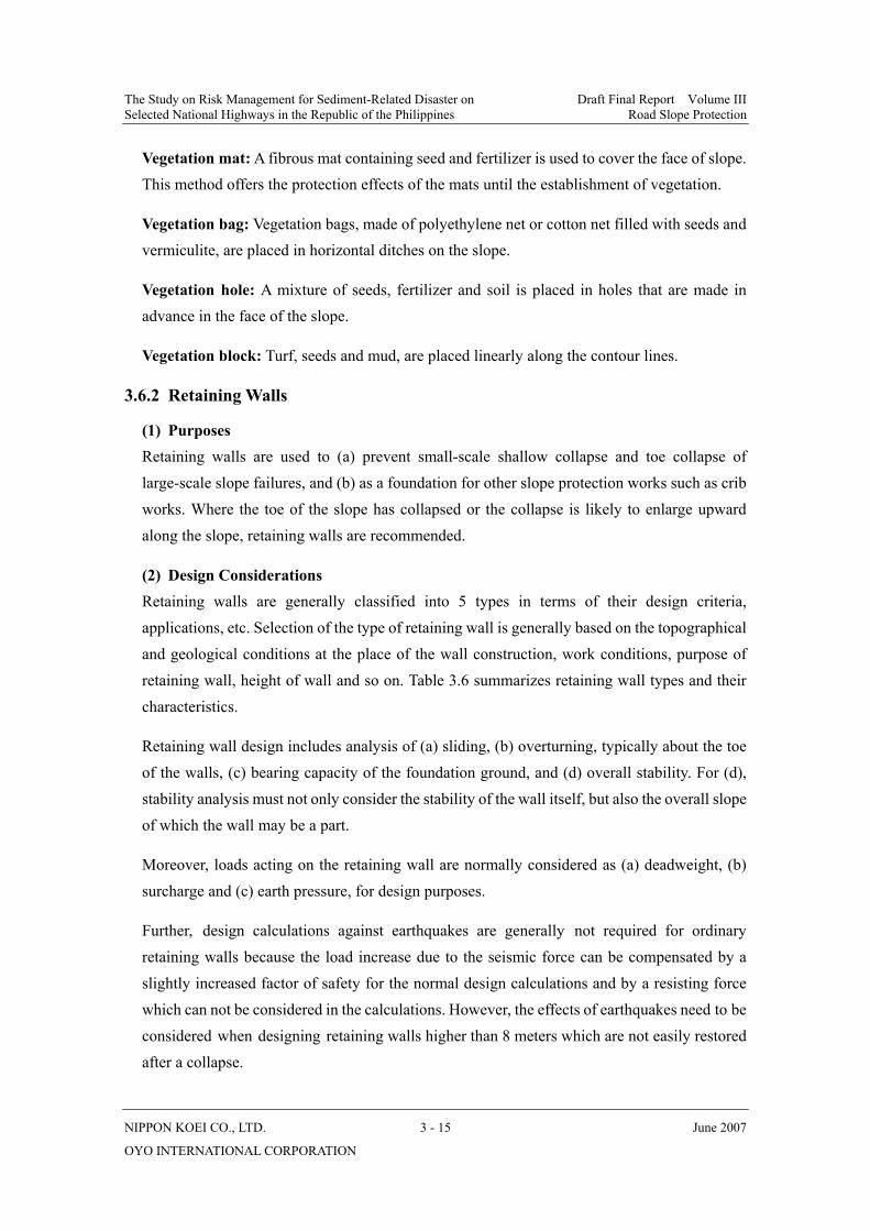
The Study on Risk Management for Sediment-Related Disaster on Draft Final Report Volume III Selected National Highways in the Republic of the Philippines Road Slope Protection
NIPPON KOEI CO., LTD. 3 - 15 June 2007
OYO INTERNATIONAL CORPORATION
Vegetation mat: A fibrous mat containing seed and fertilizer is used to cover the face of slope. This method offers the protection effects of the mats until the establishment of vegetation.
Vegetation bag: Vegetation bags, made of polyethylene net or cotton net filled with seeds and vermiculite, are placed in horizontal ditches on the slope.
Vegetation hole: A mixture of seeds, fertilizer and soil is placed in holes that are made in advance in the face of the slope.
Vegetation block: Turf, seeds and mud, are placed linearly along the contour lines.
3.6.2 Retaining Walls
(1) Purposes Retaining walls are used to (a) prevent small-scale shallow collapse and toe collapse of large-scale slope failures, and (b) as a foundation for other slope protection works such as crib works. Where the toe of the slope has collapsed or the collapse is likely to enlarge upward along the slope, retaining walls are recommended.
(2) Design Considerations Retaining walls are generally classified into 5 types in terms of their design criteria, applications, etc. Selection of the type of retaining wall is generally based on the topographical and geological conditions at the place of the wall construction, work conditions, purpose of retaining wall, height of wall and so on. Table 3.6 summarizes retaining wall types and their characteristics.
Retaining wall design includes analysis of (a) sliding, (b) overturning, typically about the toe of the walls, (c) bearing capacity of the foundation ground, and (d) overall stability. For (d), stability analysis must not only consider the stability of the wall itself, but also the overall slope of which the wall may be a part.
Moreover, loads acting on the retaining wall are normally considered as (a) deadweight, (b) surcharge and (c) earth pressure, for design purposes.
Further, design calculations against earthquakes are generally not required for ordinary retaining walls because the load increase due to the seismic force can be compensated by a slightly increased factor of safety for the normal design calculations and by a resisting force which can not be considered in the calculations. However, the effects of earthquakes need to be considered when designing retaining walls higher than 8 meters which are not easily restored after a collapse.

The Study on Risk Management for Sediment-Related Disaster on Draft Final Report Volume III Selected National Highways in the Republic of the Philippines Road Slope Protection
NIPPON KOEI CO., LTD. 3 - 16 June 2007
OYO INTERNATIONAL CORPORATION
Table 3.6 Types and Characteristics of Retaining Walls (Modification from Reference No. 3)
Type Shape Height and Gradient Characteristics Technical Note
Block
(Stone)
Masonry
• Normally less than 7.0 m in height.
• Up to 15.0 m in height for large block masonry.
• Front slope is 1:0.3 to 1:0.6 (V:H)
• Frequently used to prevent small scale collapse at the foot of the slope or to protect the slope.
• Mainly applicable for light earth pressure loads where the soil behind the wall is dense or good soil sediment.
• Structurally weak to resist the effects of an earthquake.
Gravity
• Less than 5.0 m in height.
• The width of wall base is about 0.5 to 0.7 times the height of the wall.
• Supports the earth pressure by its deadweight.
• Applicable on good ground foundations because of great ground reaction.
• Inapplicable for pile foundations.
Leaning
• Less than 10.0 m in most cases.
• Up to 15.0 m in some cases.
• Front slope is 1:0.3 to 1:0.6 (V:H)
• Supports the earth pressure by its own deadweight while being supported by the earth at the rear or by the backfill.
• Applicable for widening the existing road in mountainous terrain.
• Frequently used in places with land and topographical constraints.
Cantilever
• 3.0 to 10.0 m in height.
• The width of wall base is about 0.5 to 0.8 times the height of wall.
• Vertical wall resist the lateral load or earth pressure.
• The weight of backfill over the heel slab can be used to support the earth pressure.
• Applicable for pile foundations.
• Precast concrete is frequently used.
Counterfort
• More than 10.0 m in height.
• The width of wall base is about 0.5 to 0.7 times the height of wall
• Vertical wall and bottom slab as slab is supported on three sides.
• Counterfort type is more beneficial than cantilever type for higher walls.
• Construction of wall body and backfill is difficult.
• Applicable for pile foundations.
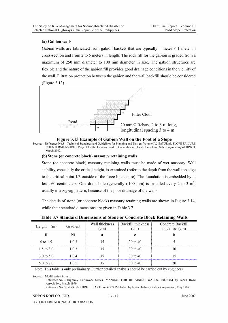
The Study on Risk Management for Sediment-Related Disaster on Draft Final Report Volume III Selected National Highways in the Republic of the Philippines Road Slope Protection
NIPPON KOEI CO., LTD. 3 - 17 June 2007
OYO INTERNATIONAL CORPORATION
(a) Gabion walls Gabion walls are fabricated from gabion baskets that are typically 1 meter × 1 meter in cross-section and from 2 to 5 meters in length. The rock fill for the gabion is graded from a maximum of 250 mm diameter to 100 mm diameter in size. The gabion structures are flexible and the nature of the gabion fill provides good drainage conditions in the vicinity of the wall. Filtration protection between the gabion and the wall backfill should be considered (Figure 3.13).
Figure 3.13 Example of Gabion Wall on the Foot of a Slope
Source: Reference No.8 Technical Standards and Guidelines for Planning and Design, Volume IV, NATURAL SLOPE FAILURE COUNTERMEASURES, Project for the Enhancement of Capability in Flood Control and Sabo Engineering of DPWH, March 2002.
(b) Stone (or concrete block) masonry retaining walls Stone (or concrete block) masonry retaining walls must be made of wet masonry. Wall stability, especially the critical height, is examined (refer to the depth from the wall top edge to the critical point 1/3 outside of the force line centre). The foundation is embedded by at least 60 centimeters. One drain hole (generally φ100 mm) is installed every 2 to 3 m2, usually in a zigzag pattern, because of the poor drainage of the walls.
The details of stone (or concrete block) masonry retaining walls are shown in Figure 3.14, while their standard dimensions are given in Table 3.7.
Table 3.7 Standard Dimensions of Stone or Concrete Block Retaining Walls
Height (m) Gradient Wall thickness (cm)
Backfill thickness (cm)
Concrete Backfill thickness (cm)
H N1 a c b
0 to 1.5 1:0.3 35 30 to 40 5
1.5 to 3.0 1:0.3 35 30 to 40 10
3.0 to 5.0 1:0.4 35 30 to 40 15
5.0 to 7.0 1:0.5 35 30 to 40 20 Note: This table is only preliminary. Further detailed analysis should be carried out by engineers.
Source: Modification from Reference No. 3 Highway Earthwork Series, MANUAL FOR RETAINING WALLS, Published by Japan Road
Association, March 1999. Reference No. 5 DESIGN GUIDE -EARTHWORKS, Published by Japan Highway Public Corporation, May 1998.
20 mm Ø Rebars, 2 to 3 m long, longitudinal spacing 3 to 4 m
Filter Cloth Road
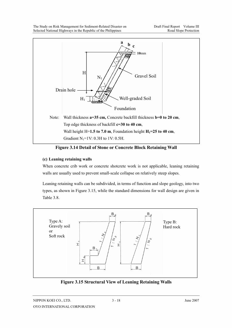
The Study on Risk Management for Sediment-Related Disaster on Draft Final Report Volume III Selected National Highways in the Republic of the Philippines Road Slope Protection
NIPPON KOEI CO., LTD. 3 - 18 June 2007
OYO INTERNATIONAL CORPORATION
Figure 3.14 Detail of Stone or Concrete Block Retaining Wall
(c) Leaning retaining walls When concrete crib work or concrete shotcrete work is not applicable, leaning retaining walls are usually used to prevent small-scale collapse on relatively steep slopes.
Leaning retaining walls can be subdivided, in terms of function and slope geology, into two types, as shown in Figure 3.15, while the standard dimensions for wall design are given in Table 3.8.
Figure 3.15 Structural View of Leaning Retaining Walls
Note: Wall thickness a=35 cm, Concrete backfill thickness b=0 to 20 cm, Top edge thickness of backfill c=30 to 40 cm, Wall height H=1.5 to 7.0 m, Foundation height H1=25 to 40 cm, Gradient N1=1V: 0.3H to 1V: 0.5H.
c 10mm
H1
HN1
Foundation
Well-graded Soil
Gravel Soil
Drain hole
a b
Type A: Gravely soil or Soft rock
Type B: Hard rock

The Study on Risk Management for Sediment-Related Disaster on Draft Final Report Volume III Selected National Highways in the Republic of the Philippines Road Slope Protection
NIPPON KOEI CO., LTD. 3 - 19 June 2007
OYO INTERNATIONAL CORPORATION
Table 3.8 Standard Dimensions of Leaning Retaining Walls
Height (m)
Front slope
Back slope
Base width (cm)
Base thickness
(cm)
Foundation front width
(cm)
Top edge width (cm) Type of Ground
H1 N1 N2 B H2 B1 B2
3.0 0.60 0.40 1.62 0.80 1.00 0.50 (A) Gravely soil,
soft rock 5.0 0.60 0.40 1.75 1.00 0.90 0.45
3.0 0.40 0.30 0.75 0 0 0.45
5.0 0.40 0.30 0.95 0 0 0.45 (B) Hard rock
8.0 0.40 0.30 1.25 0 0 0.45 Source: Modification from Reference No. 5 DESIGN GUIDE -EARTHWORKS, Published by Japan Highway Public
Corporation, May 1998.
As shown in Figure 3.15, Type A is generally used as protection from small rock falls and design calculations against earth pressure is not conducted. The height of the wall shall be determined on the basis of the bearing ground, as shown in Table 3.9.
Table 3.9 Determination of Wall Height by Bearing Ground Height H (m) Bearing Ground Less than 10 Rock
Clayey soil C(t/m2) Sandy Soil (N value) Less than 7 C ≧ 7 N ≧ 30 Less than 5 C ≧ 6 N ≧ 25 Less than 3 C ≧ 4 N ≧ 20
Source: Modification from Reference No. 5 DESIGN GUIDE -EARTHWORKS, Published by Japan Highway Public Corporation, May 1998.
Moreover, the bedding depth for the wall is 1.0 m in principle, but may be reduced to 0.5 m where there is a bearing layer of hard rock.
(d) Gravity type retaining walls For gravity type retaining walls, design considerations involve the above-mentioned analyses of the four states, namely, sliding, overturning, bearing capacity and overall stability. In determining the dimensions of the wall, it is desirable that the width, B, of the bottom slab is about 0.5 to 0.7 times the height of the retaining wall and that the thickness of the top edge is between 15 cm and 40 cm.
(e) Concrete crib retaining walls Crib retaining walls, which are usually fabricated from pre-cast reinforced concrete elements, are flexible due to the segmental nature of the elements and are somewhat resistant to differential settlement and deformation.
Especially when the ground deforms considerably and there is a large amount of spring

The Study on Risk Management for Sediment-Related Disaster on Draft Final Report Volume III Selected National Highways in the Republic of the Philippines Road Slope Protection
NIPPON KOEI CO., LTD. 3 - 20 June 2007
OYO INTERNATIONAL CORPORATION
water in the potential soil slope collapse areas, crib retaining walls are applicable.
Stability is calculated for the whole structure as well as for several horizontal sections. Slope stability calculations should include the potential failure surface above the toe of the wall. Earth pressure calculations for the walls are similar to those for the gravity type retaining walls (Figure 3.16).
Moreover, the space inside the cribs should be filled with cobbles.
Figure 3.16 Detail of Concrete Crib Retaining Wall Source: Modification from Reference No. 5 DESIGN GUIDE -EARTHWORKS, Published by Japan Highway Public Corporation, May 1998.
3.6.3 Pitching Works Pitching works include concrete pitching, stone pitching and block pitching. They are commonly used on slopes gentler than 1V:1.0H. When the slope gradient is greater than 1V:1.0H, concrete retaining walls, stone masonry retaining walls or block masonry retaining walls may be adopted.
(1) Purposes Pitching works are applied to prevent surface weathering, scouring, stripping and erosion and, in some cases, to prevent small-scale soil slope collapse.
(2) Design Considerations Stone pitching and block pitching are used for non-cohesive sediments, mudstone and
collapsible clayey soils with a slope gradient less than 1V:1.0H. On the other hand, concrete pitching is employed for jointed rock slopes with a possibility of weathering and stripping. For large and/or steep rock slopes, it is desirable to reinforce the concrete with reinforcing bars or wire mesh. Adequate methods are selected by referring to Table 3.10.
Note: 1) Height of Wall: H = 3.0 to 10.0 m, 2) Front Slope: 1V: 0.3H to 1V: 0.5H 3) Depth of Embedment h1=0.5m to 1.0m
Road
Potential soil slope
Concrete crib retaining wallh1

The Study on Risk Management for Sediment-Related Disaster on Draft Final Report Volume III Selected National Highways in the Republic of the Philippines Road Slope Protection
NIPPON KOEI CO., LTD. 3 - 21 June 2007
OYO INTERNATIONAL CORPORATION
Table 3.10 Selection of Pitching Works
Type Pitching thickness (cm)
Gradient (V:H)
Height (m) Geological conditions
25 to 35 1:1.0 to 1:1.5 Less than 5.0Stone
Less than 5 1:1.5 to 1:1.8 −
35 1:1.0 to 1:1.5 Less than 3.0Block
Less than 12 1:1.5 to 1:1.8 −
Sediments, talus, cone mudstone and collapsible clayey soils.
Concrete More than 20 less than 1:0.5 − Reinforced Concrete More than 20 Over 1:0.5 −
Bedrock with numerous joints and with a possibility of weathering and stripping.
Note: The table is only preliminary. Further detailed analysis is to be carried out by the engineer.
Source: Modification from Reference No. 1 Highway Earthwork Series, MANUAL FOR SLOPE PROTECTION, Published by Japan Road
Association, March 1999. Reference No. 5 DESIGN GUIDE -EARTHWORKS, Published by Japan Highway Public Corporation, May 1998.
Moreover, drain holes of about 5 cm diameter shall be provided every 2 to 4 m2, regardless of the presence of spring water or seepage water.
Figure 3.17 Examples of Pitching Works
3.6.4 Crib Works
Crib works include concrete block cribs, shotcrete cribs and cast-in-place concrete crib works. These are commonly used on steep slopes of highly weathered or heavily jointed rocks with abundant springs, especially where spalls cannot be fixed with shotcrete works.
Top concrete
Backfilling concrete
Backfilling material
Gravel soil
Cobblestone Foundation
Drain hole
Reinforced concrete
Concrete Foundation
Reinforced wire Drain hole
Precast concrete block
Anchor pin
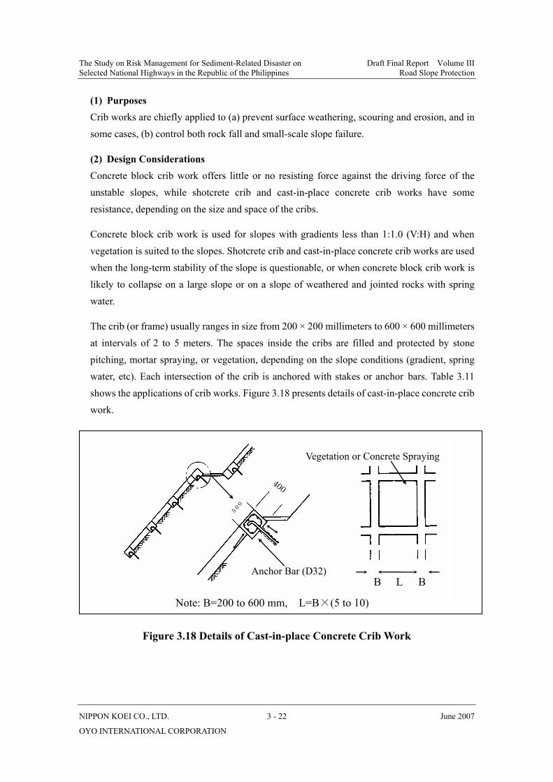
The Study on Risk Management for Sediment-Related Disaster on Draft Final Report Volume III Selected National Highways in the Republic of the Philippines Road Slope Protection
NIPPON KOEI CO., LTD. 3 - 22 June 2007
OYO INTERNATIONAL CORPORATION
(1) Purposes Crib works are chiefly applied to (a) prevent surface weathering, scouring and erosion, and in some cases, (b) control both rock fall and small-scale slope failure.
(2) Design Considerations Concrete block crib work offers little or no resisting force against the driving force of the unstable slopes, while shotcrete crib and cast-in-place concrete crib works have some resistance, depending on the size and space of the cribs.
Concrete block crib work is used for slopes with gradients less than 1:1.0 (V:H) and when vegetation is suited to the slopes. Shotcrete crib and cast-in-place concrete crib works are used when the long-term stability of the slope is questionable, or when concrete block crib work is likely to collapse on a large slope or on a slope of weathered and jointed rocks with spring water.
The crib (or frame) usually ranges in size from 200 × 200 millimeters to 600 × 600 millimeters at intervals of 2 to 5 meters. The spaces inside the cribs are filled and protected by stone pitching, mortar spraying, or vegetation, depending on the slope conditions (gradient, spring water, etc). Each intersection of the crib is anchored with stakes or anchor bars. Table 3.11 shows the applications of crib works. Figure 3.18 presents details of cast-in-place concrete crib work.
Figure 3.18 Details of Cast-in-place Concrete Crib Work
L B BAnchor Bar (D32)
Vegetation or Concrete Spraying
Note: B=200 to 600 mm, L=B×(5 to 10)
5 0 0
400
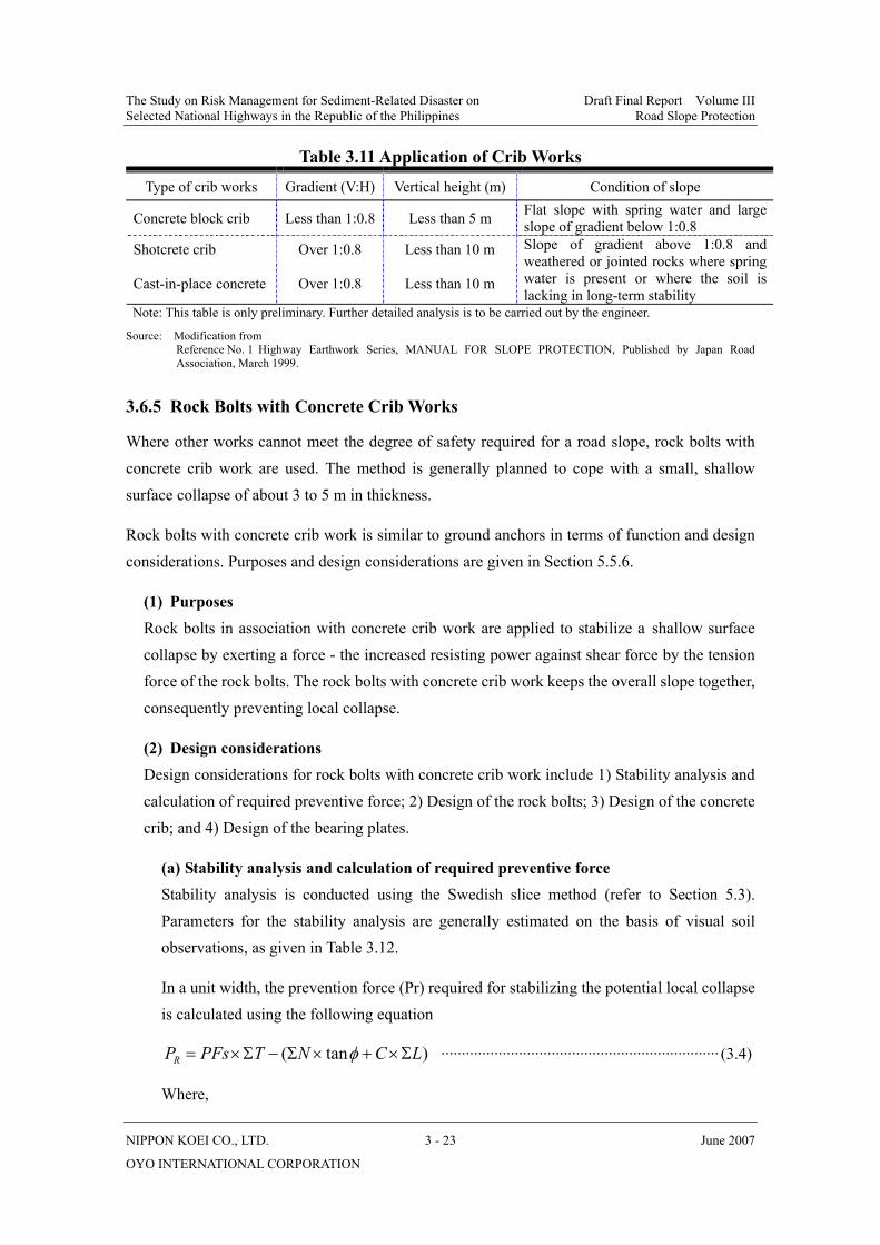
The Study on Risk Management for Sediment-Related Disaster on Draft Final Report Volume III Selected National Highways in the Republic of the Philippines Road Slope Protection
NIPPON KOEI CO., LTD. 3 - 23 June 2007
OYO INTERNATIONAL CORPORATION
Table 3.11 Application of Crib Works
Type of crib works Gradient (V:H) Vertical height (m) Condition of slope
Concrete block crib Less than 1:0.8 Less than 5 m Flat slope with spring water and large slope of gradient below 1:0.8
Shotcrete crib Over 1:0.8 Less than 10 m
Cast-in-place concrete Over 1:0.8 Less than 10 m
Slope of gradient above 1:0.8 and weathered or jointed rocks where spring water is present or where the soil is lacking in long-term stability
Note: This table is only preliminary. Further detailed analysis is to be carried out by the engineer.
Source: Modification from Reference No. 1 Highway Earthwork Series, MANUAL FOR SLOPE PROTECTION, Published by Japan Road
Association, March 1999.
3.6.5 Rock Bolts with Concrete Crib Works
Where other works cannot meet the degree of safety required for a road slope, rock bolts with concrete crib work are used. The method is generally planned to cope with a small, shallow surface collapse of about 3 to 5 m in thickness.
Rock bolts with concrete crib work is similar to ground anchors in terms of function and design considerations. Purposes and design considerations are given in Section 5.5.6.
(1) Purposes Rock bolts in association with concrete crib work are applied to stabilize a shallow surface collapse by exerting a force - the increased resisting power against shear force by the tension force of the rock bolts. The rock bolts with concrete crib work keeps the overall slope together, consequently preventing local collapse.
(2) Design considerations Design considerations for rock bolts with concrete crib work include 1) Stability analysis and calculation of required preventive force; 2) Design of the rock bolts; 3) Design of the concrete crib; and 4) Design of the bearing plates.
(a) Stability analysis and calculation of required preventive force Stability analysis is conducted using the Swedish slice method (refer to Section 5.3). Parameters for the stability analysis are generally estimated on the basis of visual soil observations, as given in Table 3.12.
In a unit width, the prevention force (Pr) required for stabilizing the potential local collapse is calculated using the following equation
)tan( LCNTPFsPR Σ×+×Σ−Σ×= φ ···································································· (3.4)
Where,
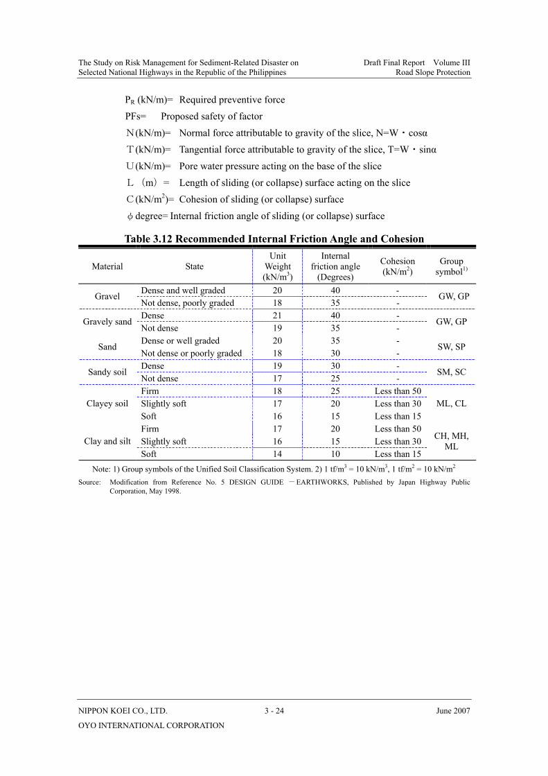
The Study on Risk Management for Sediment-Related Disaster on Draft Final Report Volume III Selected National Highways in the Republic of the Philippines Road Slope Protection
NIPPON KOEI CO., LTD. 3 - 24 June 2007
OYO INTERNATIONAL CORPORATION
PR (kN/m)= Required preventive force PFs= Proposed safety of factor
N(kN/m)= Normal force attributable to gravity of the slice, N=W・cosα T(kN/m)= Tangential force attributable to gravity of the slice, T=W・sinα U(kN/m)= Pore water pressure acting on the base of the slice L(m)= Length of sliding (or collapse) surface acting on the slice C(kN/m2)= Cohesion of sliding (or collapse) surface φdegree= Internal friction angle of sliding (or collapse) surface
Table 3.12 Recommended Internal Friction Angle and Cohesion
Material State Unit
Weight (kN/m3)
Internal friction angle
(Degrees)
Cohesion (kN/m2)
Group symbol1)
Dense and well graded 20 40 - Gravel Not dense, poorly graded 18 35 -
GW, GP
Dense 21 40 - Gravely sand
Not dense 19 35 - GW, GP
Dense or well graded 20 35 - Sand
Not dense or poorly graded 18 30 - SW, SP
Dense 19 30 - Sandy soil
Not dense 17 25 - SM, SC
Firm 18 25 Less than 50 Slightly soft 17 20 Less than 30 Clayey soil Soft 16 15 Less than 15
ML, CL
Firm 17 20 Less than 50 Slightly soft 16 15 Less than 30 Clay and silt Soft 14 10 Less than 15
CH, MH, ML
Note: 1) Group symbols of the Unified Soil Classification System. 2) 1 tf/m3 = 10 kN/m3, 1 tf/m2 = 10 kN/m2
Source: Modification from Reference No. 5 DESIGN GUIDE -EARTHWORKS, Published by Japan Highway Public Corporation, May 1998.
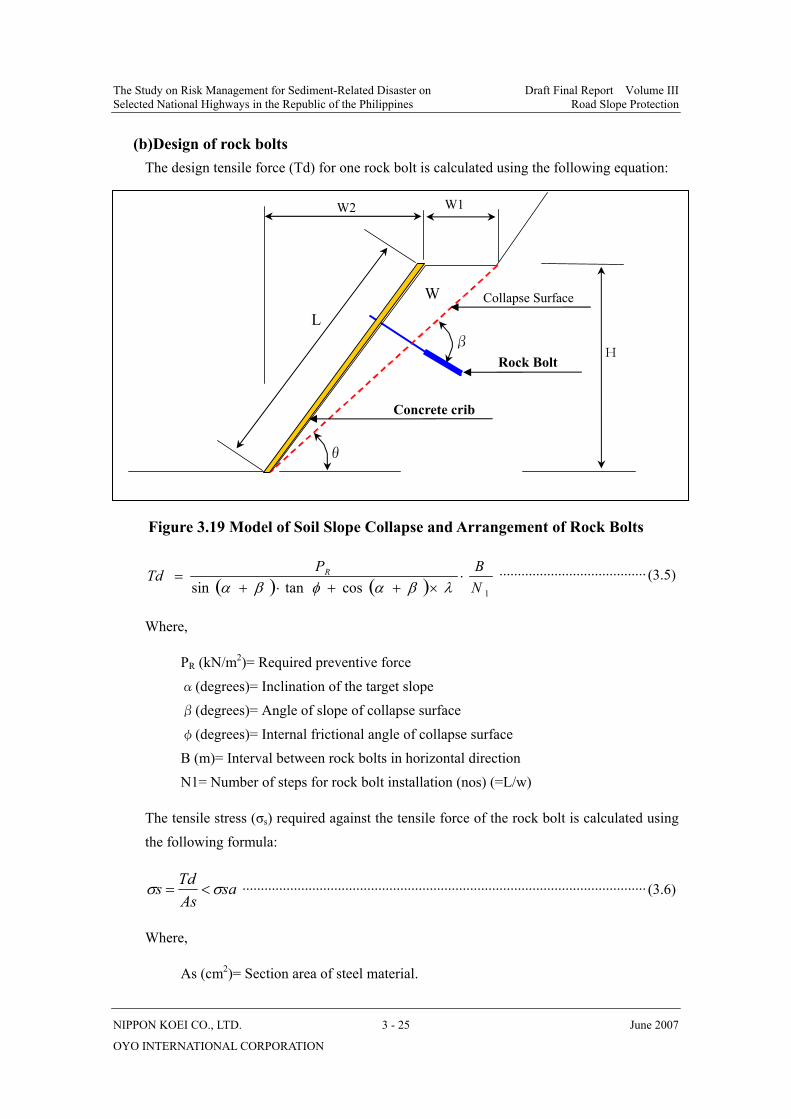
The Study on Risk Management for Sediment-Related Disaster on Draft Final Report Volume III Selected National Highways in the Republic of the Philippines Road Slope Protection
NIPPON KOEI CO., LTD. 3 - 25 June 2007
OYO INTERNATIONAL CORPORATION
(b) Design of rock bolts The design tensile force (Td) for one rock bolt is calculated using the following equation:
Figure 3.19 Model of Soil Slope Collapse and Arrangement of Rock Bolts
( ) ( ) 1costansin NBPTd R ⋅
×++⋅+=
λβαφβα········································ (3.5)
Where,
PR (kN/m2)= Required preventive force
α(degrees)= Inclination of the target slope β(degrees)= Angle of slope of collapse surface φ(degrees)= Internal frictional angle of collapse surface B (m)= Interval between rock bolts in horizontal direction N1= Number of steps for rock bolt installation (nos) (=L/w)
The tensile stress (σs) required against the tensile force of the rock bolt is calculated using the following formula:
saAsTds σσ <= ·············································································································· (3.6)
Where,
As (cm2)= Section area of steel material.
W2 W1
β
L
H
θ
Collapse Surface W
Rock Bolt
Concrete crib
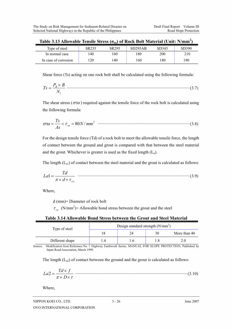
The Study on Risk Management for Sediment-Related Disaster on Draft Final Report Volume III Selected National Highways in the Republic of the Philippines Road Slope Protection
NIPPON KOEI CO., LTD. 3 - 26 June 2007
OYO INTERNATIONAL CORPORATION
Table 3.13 Allowable Tensile Stress (σsa) of Rock Bolt Material (Unit: N/mm2) Type of steel SR235 SR295 SD295AB SD345 SD390
In normal case 140 160 180 200 210 In case of corrosion 120 140 160 180 190
Shear force (Ts) acting on one rock bolt shall be calculated using the following formula:
1NBPTs R ×= ·················································································································· (3.7)
The shear stress ( aστ ) required against the tensile force of the rock bolt is calculated using
the following formula:
2/80 mmNAsTsa sa =<= τστ ····················································································· (3.8)
For the design tensile force (Td) of a rock bolt to meet the allowable tensile force, the length of contact between the ground and grout is compared with that between the steel material and the grout. Whichever is greater is used as the fixed length (La).
The length (La1) of contact between the steel material and the grout is calculated as follows:
cadTdLa
τπ ××=1 ········································································································ (3.9)
Where,
d (mm)= Diameter of rock bolt
caτ (N/mm2)= Allowable bond stress between the grout and the steel
Table 3.14 Allowable Bond Stress between the Grout and Steel Material Design standard strength (N/mm2)
Type of steel 18 24 30 More than 40
Different shape 1.4 1.6 1.8 2.0 Source: Modification from Reference No. 1 Highway Earthwork Series, MANUAL FOR SLOPE PROTECTION, Published by
Japan Road Association, March 1999.
The length (La2) of contact between the ground and the grout is calculated as follows:
τπ ×××
=DfTdLa2 ········································································································(3.10)
Where,
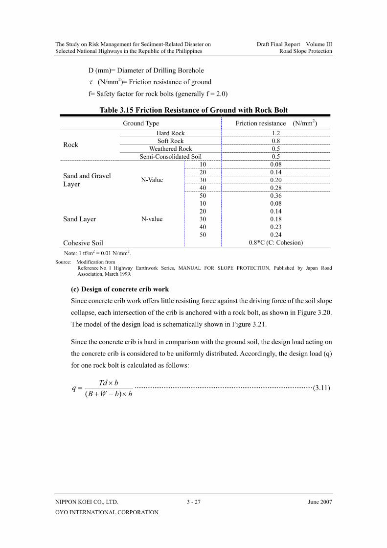
The Study on Risk Management for Sediment-Related Disaster on Draft Final Report Volume III Selected National Highways in the Republic of the Philippines Road Slope Protection
NIPPON KOEI CO., LTD. 3 - 27 June 2007
OYO INTERNATIONAL CORPORATION
D (mm)= Diameter of Drilling Borehole τ (N/mm2)= Friction resistance of ground
f= Safety factor for rock bolts (generally f = 2.0)
Table 3.15 Friction Resistance of Ground with Rock Bolt
Ground Type Friction resistance (N/mm2) Hard Rock 1.2 Soft Rock 0.8
Weathered Rock 0.5 Rock Semi-Consolidated Soil 0.5
10 0.08 20 0.14 30 0.20 40 0.28
Sand and Gravel Layer N-Value
50 0.36 10 0.08 20 0.14 30 0.18 40 0.23
Sand Layer N-value
50 0.24 Cohesive Soil 0.8*C (C: Cohesion) Note: 1 tf/m2 = 0.01 N/mm2.
Source: Modification from Reference No. 1 Highway Earthwork Series, MANUAL FOR SLOPE PROTECTION, Published by Japan Road
Association, March 1999.
(c) Design of concrete crib work Since concrete crib work offers little resisting force against the driving force of the soil slope collapse, each intersection of the crib is anchored with a rock bolt, as shown in Figure 3.20. The model of the design load is schematically shown in Figure 3.21.
Since the concrete crib is hard in comparison with the ground soil, the design load acting on the concrete crib is considered to be uniformly distributed. Accordingly, the design load (q) for one rock bolt is calculated as follows:
hbWBbTdq×−+
×=
)(···································································································(3.11)

The Study on Risk Management for Sediment-Related Disaster on Draft Final Report Volume III Selected National Highways in the Republic of the Philippines Road Slope Protection
NIPPON KOEI CO., LTD. 3 - 28 June 2007
OYO INTERNATIONAL CORPORATION
Figure 3.20 Arrangement of Rock Bolts
Figure 3.21 Model of Design Load
The maximum moment (Mmax) acting on the concrete crib is calculated using the following formula:
9max WBqM ××
= ··································································································(3.12)
The maximum shear force (Smax) acting on the concrete crib (or frame) is calculated using the following formula:
bB
Rock Bolt W W W
Concrete crib
h
W
b
B h
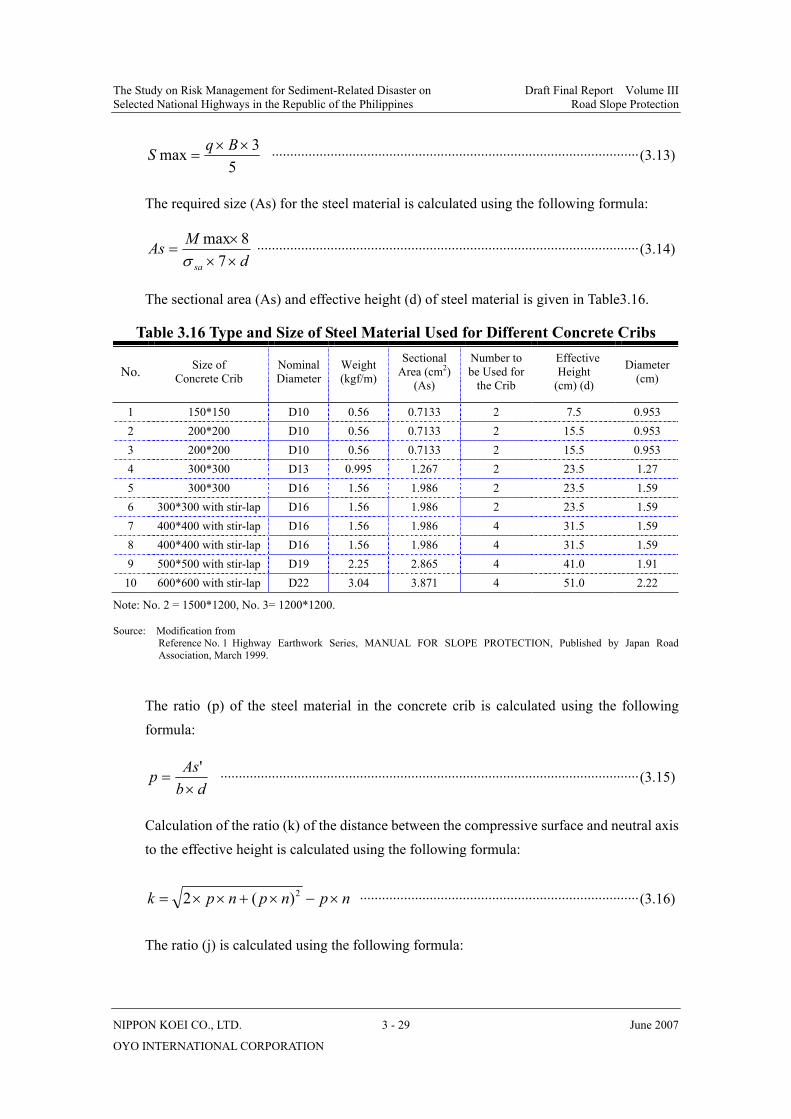
The Study on Risk Management for Sediment-Related Disaster on Draft Final Report Volume III Selected National Highways in the Republic of the Philippines Road Slope Protection
NIPPON KOEI CO., LTD. 3 - 29 June 2007
OYO INTERNATIONAL CORPORATION
53max ××
=BqS ····································································································(3.13)
The required size (As) for the steel material is calculated using the following formula:
dMAssa ××
×=
78max
σ········································································································(3.14)
The sectional area (As) and effective height (d) of steel material is given in Table3.16.
Table 3.16 Type and Size of Steel Material Used for Different Concrete Cribs
No. Size of Concrete Crib
Nominal Diameter
Weight (kgf/m)
Sectional Area (cm2)
(As)
Number to be Used for
the Crib
Effective Height
(cm) (d)
Diameter (cm)
1 150*150 D10 0.56 0.7133 2 7.5 0.953 2 200*200 D10 0.56 0.7133 2 15.5 0.953 3 200*200 D10 0.56 0.7133 2 15.5 0.953 4 300*300 D13 0.995 1.267 2 23.5 1.27 5 300*300 D16 1.56 1.986 2 23.5 1.59 6 300*300 with stir-lap D16 1.56 1.986 2 23.5 1.59 7 400*400 with stir-lap D16 1.56 1.986 4 31.5 1.59 8 400*400 with stir-lap D16 1.56 1.986 4 31.5 1.59 9 500*500 with stir-lap D19 2.25 2.865 4 41.0 1.91
10 600*600 with stir-lap D22 3.04 3.871 4 51.0 2.22
Note: No. 2 = 1500*1200, No. 3= 1200*1200.
Source: Modification from Reference No. 1 Highway Earthwork Series, MANUAL FOR SLOPE PROTECTION, Published by Japan Road
Association, March 1999.
The ratio (p) of the steel material in the concrete crib is calculated using the following formula:
dbAsp×
='
··················································································································(3.15)
Calculation of the ratio (k) of the distance between the compressive surface and neutral axis to the effective height is calculated using the following formula:
npnpnpk ×−×+××= 2)(2 ············································································(3.16)
The ratio (j) is calculated using the following formula:
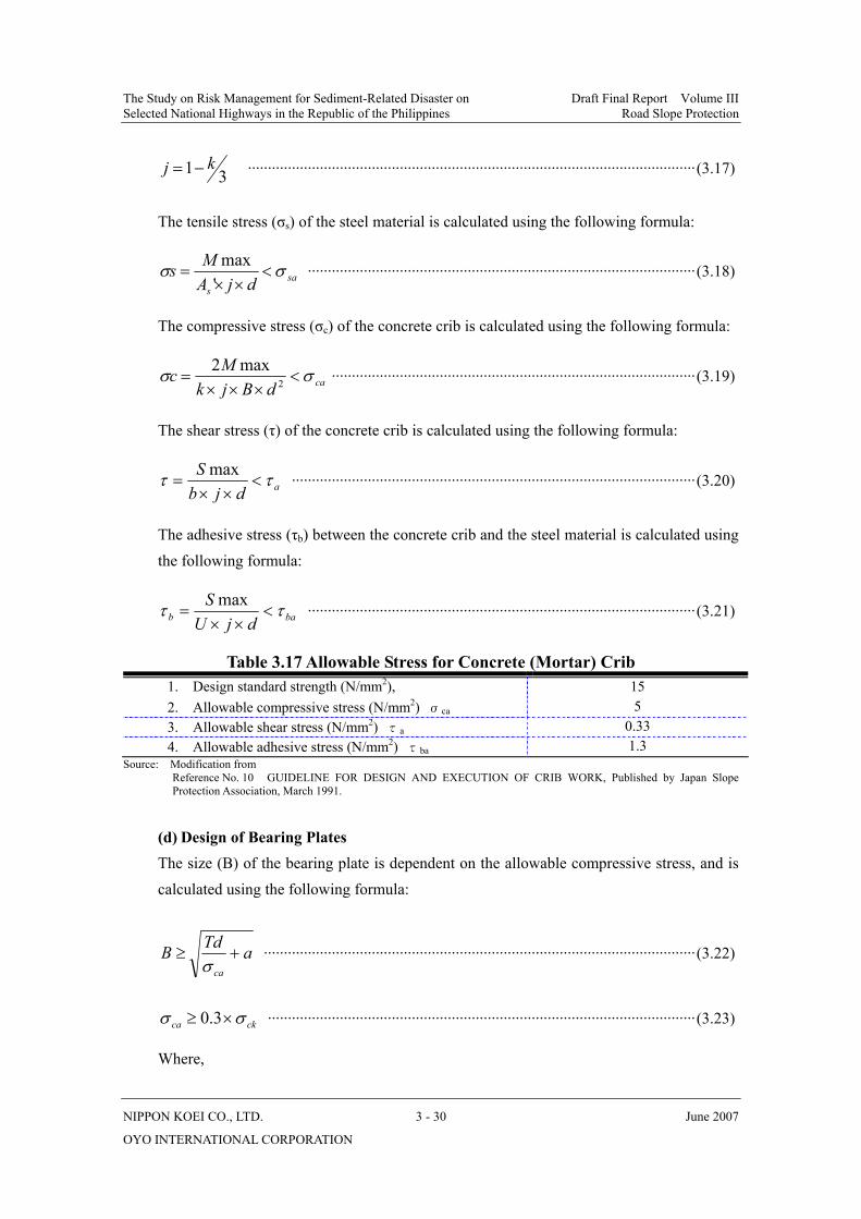
The Study on Risk Management for Sediment-Related Disaster on Draft Final Report Volume III Selected National Highways in the Republic of the Philippines Road Slope Protection
NIPPON KOEI CO., LTD. 3 - 30 June 2007
OYO INTERNATIONAL CORPORATION
31 kj −= ················································································································(3.17)
The tensile stress (σs) of the steel material is calculated using the following formula:
sas djAMs σσ <
××=
'max
·································································································(3.18)
The compressive stress (σc) of the concrete crib is calculated using the following formula:
cadBjkMc σσ <
×××= 2
max2···························································································(3.19)
The shear stress (τ) of the concrete crib is calculated using the following formula:
adjbS ττ <
××=
max ·····································································································(3.20)
The adhesive stress (τb) between the concrete crib and the steel material is calculated using the following formula:
bab djUS ττ <
××=
max ·································································································(3.21)
Table 3.17 Allowable Stress for Concrete (Mortar) Crib 1. Design standard strength (N/mm2), 15 2. Allowable compressive stress (N/mm2) σca 5 3. Allowable shear stress (N/mm2) τa 0.33 4. Allowable adhesive stress (N/mm2) τba 1.3
Source: Modification from Reference No. 10 GUIDELINE FOR DESIGN AND EXECUTION OF CRIB WORK, Published by Japan Slope
Protection Association, March 1991.
(d) Design of Bearing Plates The size (B) of the bearing plate is dependent on the allowable compressive stress, and is calculated using the following formula:
aTdBca
+≥σ
············································································································(3.22)
ckca σσ ×≥ 3.0 ···········································································································(3.23)
Where,

The Study on Risk Management for Sediment-Related Disaster on Draft Final Report Volume III Selected National Highways in the Republic of the Philippines Road Slope Protection
NIPPON KOEI CO., LTD. 3 - 31 June 2007
OYO INTERNATIONAL CORPORATION
B= the minimum width required (mm) Td= Design tensile force for one rock bolt (kN/nos) σca= Allowable compressive stress (N/mm2) σck= Design standard strength (N/mm2) a= hole area (mm2)