final nccm
TRANSCRIPT
7/28/2019 Final Nccm
http://slidepdf.com/reader/full/final-nccm 1/8
Diagnosis of Induction Motor faults using Motor Current Signature
Analysis at VIZAG STEEL
By
C.Pavan Sameer Kumar, M anagement Tr ainee (Techni cal), Visakhapatnam Steel Plant.
Abstract
Induction motors are the most widely used electrical drive systems. Hence it is of immense
importance to reduce breakdowns of induction motors and prevent unscheduled downtimes. Motor
current signature analysis (MCSA) is a condition monitoring technique that is now being widely
used to diagnose problems such as broken rotor bars, abnormal levels of air gap eccentricity,
shorted turns in low voltage stator windings and certain mechanical problems in an induction
motor using stator current on no load. Using MCSA at VIZAG STEEL problems at production
units like Coke Oven have been detected at an early stage, thus avoided secondary damage and
complete failure of the motor. Detailed case study at VIZAG STEEL showing the complete
interpretation of MCSA is presented to aid practicing engineers .
1. INTRODUCTION
Induction Motors are a critical component of many industrial processes. Hence it is of
immense importance to reduce maintenance costs of induction motors and prevent
unscheduled downtimes that result in lost production and financial income. Condition
monitoring of the dynamic performance of induction drives received considerable
attention in recent years as it is crucial to effective monitoring and increased reliability of
the plant. The Motor Current Signature Analysis (MCSA) is considered the most popular
fault detection method now a days because it can easily detect the common machine faults
such as turn to turn short circuit, cracked /broken rotor bars, bearing deterioration etc..
The present paper discusses the fundamentals of Motor Current Signature Analysis
(MCSA) plus condition monitoring of the induction motor using MCSA. It also presents
an industrial case study wherein a catastrophic failure of an induction motor (Mill Fan 9
of Coke Oven) at VIZAG STEEL has been avoided by early detection using MCSA and
by initiating corrective measures.

7/28/2019 Final Nccm
http://slidepdf.com/reader/full/final-nccm 2/8
2. METHODOLOGY
An Industrial case study of condition monitoring using MCSA is presented in the
following sections. Section 3 introduces a typical MCSA system, Section 4 deals with
problem description, Section 5 proceeds with the effects of cracked rotor bars and
collection of data using MCSA, Section 6 deals with the analysis of MCSA data and the
results found on dismantling the motor. It also mentions the corrective action initiated.
Section 7 proceeds to Conclusion and section 8 include References.
3. MOTOR CURRENT SIGNATURE ANALYSIS (MCSA)
Motor current signature analysis is the online analysis of current to detect faults in a three- phase induction motor drive. MCSA provides a non-intrusive method for detecting
mechanical and electrical problems in motor driven rotating equipment. Motor current
analyzer applies techniques to capture frequency signature of electric line current to
measure the variation in the flux of the electric motors. The basis for MCSA is that an
electric motor driving a mechanical load acts as an efficient, continuously available
transducer. The motor senses mechanical load variations and converts them into electrical
current variations which can be monitored and recorded at convenient location away from
the operating equipment. Periodic MCSA can provide a more subtle indication of rotor
condition, distortion, coupling or gear wear etc. Analysis of these variations can provide
an indication of machine condition, which may be trended over time to provide an early
warning of machine deterioration or process alteration.
Figure1. MCSA System Configuration
7/28/2019 Final Nccm
http://slidepdf.com/reader/full/final-nccm 3/8
3.1.1 HOW MCSA IS USED?
Motor current analyzer consists of one current collector clamp probe and one analyzer.
Probe collects the data and analyzer analysis the motor input current data with display.
Clamps on probe are placed around supply cable of LT motor (CT secondary wire, if available) and for HT motors around CT secondary wire in the MCC panel. A basic
MCSA instrumentation system will consist of the following:
A current transformer (CT) to sense the signal.
A resistive shunt across the output of the CT-note that CTs are available with
internal shunts.
An MCSA instrument (or spectrum analyzer) to produce the current spectrum or
signature.
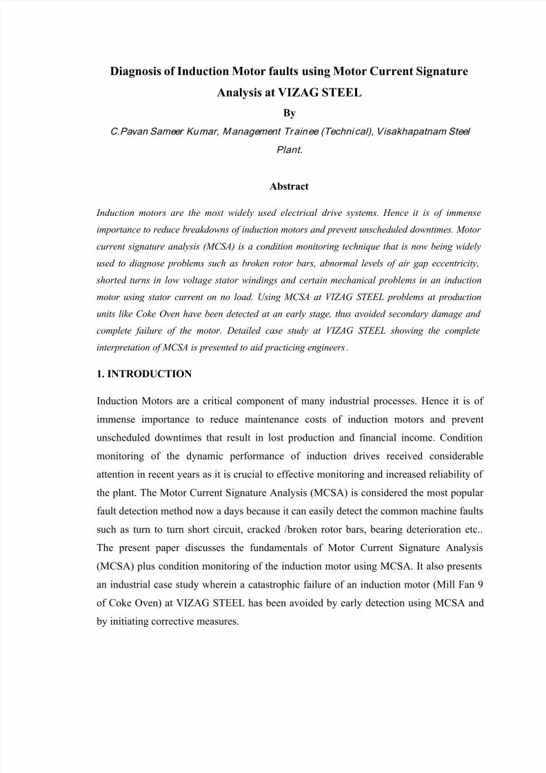
The various faults that may occur in an induction motor, the probable causes,
consequences and remedial measures to be taken are indicate below.
Faults in an Induction Motor
Component
Abnormality or
deviation Possible Causes ConsequencesAction Required
Stator
Winding
Increase in Stator
Current Winding Short
Stator burn-out
Winding Repair Over Heating
Unbalance
Currents
More Leakage Current Insulation DamageUn-symmetrical
currentsRe-insulation
More Stator Temperature
Winding Short
Early Winding
burn-outWinding Repair
Core Damage Reduced Efficiency Core Repair
Unbalanced winding
Reduced Efficiency
Winding Repair Reduced TorqueAbnormal Noise
Rotor side Less Torque
Rotor Bar break Stator-Rotor Rub Motor Repair
End Ring break Fluctuating torque Rotor Repair
Non-Uniform air-gap More slip Air-gap correction
Table1. Faults in an Induction Motor

7/28/2019 Final Nccm
http://slidepdf.com/reader/full/final-nccm 4/8
4. PROBLEM DESCRIPTION
At VIZAG STEEL, all HT motors are monitored on a monthly basis to check for any
abnormality. The Condition Monitoring Method used is MCSA. MCSA gives information
such as percentage of current unbalance, distortion index and delta db value of theinduction motor. MCSA conducted on CDCP (Coke Dry Cooling Plant) Mill Fan-9 of
Coke Oven(CO) indicated that the delta db value (35.62) is much less than the required
norm i.e. 40 db. The Technical Specifications of CDCP Mill Fan-9 are tabulated below.
VSP CO Mill Fan Equipment Details
Voltage 6.6 KV
Current 71 A
Speed 1500 rpm
Rating 630 Kw
No of Poles 6
Operating Frequency 50 Hz
No of Rotor Bars 58
Table2. Coke Oven Mill Fan-9 Equipment details
5. CRACKED ROTOR BARS IN INDUCTION MOTOR
A broken or cracked rotor bar in the motor create heating & thermal expansion,
especially in the core while motor is running under over load or subject to frequent
start with longer start time. This will cause
Adjacent rotor bars to break
Loosening of the broken bar
If the broken bars work out of the motor, then it rubs the stator winding insulation and
damage the stator -- that results catastrophic failure. When a squirrel cage induction
motor is running with cracked rotor bar, the broken rotor bars will cause localized
heating and also cause marginal increase in current in adjacent bars.
The motor current signature waveform appearance will have presence of side
band peak. The side band peak will appear at a frequency off set from the line

7/28/2019 Final Nccm
http://slidepdf.com/reader/full/final-nccm 5/8
frequency equal to the no. of poles times the slip frequency (N P X S F). The side band
peak appearance will help for diagnosing the faulty rotor bars. The amplitude of the
side band will increase with the severity of the no. of rotor bar cracks or opened.
5.1 SEVERITY OF CRACKED ROTOR BARS
A commonly used indicator of the presence and severity of rotor bar faults is the dB
amplitude difference between the amplitude of side band peak and the amplitude of
the line frequency
5.1.1 CALCULATION OF SIDE BAND FREQUENCY
Let us take an example of a blower motor running with the following parameters.
Fr = rotational frequency, L f = Line frequency, N P = No. of poles, S F = slip frequency
LSSB = Lower slip side band of Line frequency.
SF = (2* L f /NP) - F r
Then LSSB = L f – (NP*S F).
5.2 FAULT CRITERIA
A general rule of fault criteria of rotor bar crack for Sq. cage motor running with more
than 50 % load is
The measured delta dB difference between the amplitude of LSSB peak and line
frequency peak is of greater than 40 then motor does not have rotor problem
If the delta dB is less than 40, indicates starting of degradation of rotor bars,
which required to be closed monitoring for trending.
If the delta dB value continues to be decreasing, then it is preferred to dismantle
the rotor for inspection and do repair work.
6. ANALYSIS OF MCSA DATA
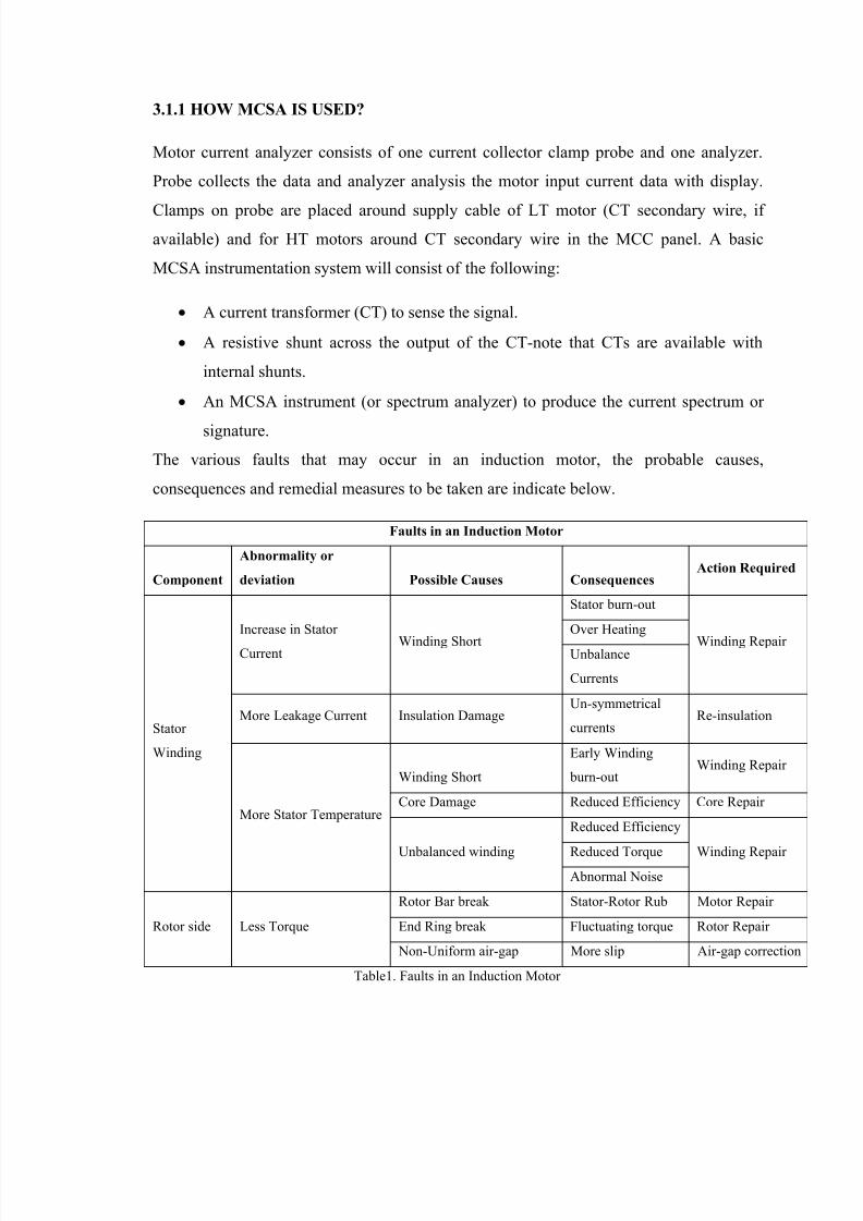
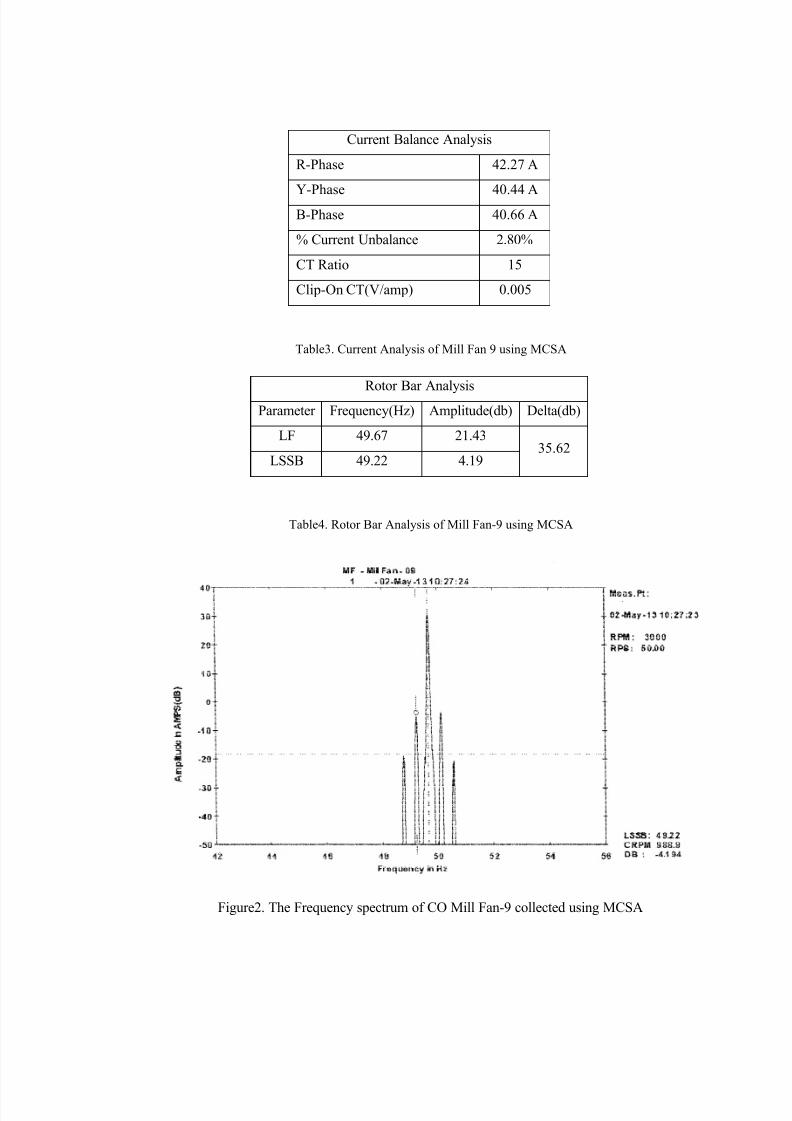
The data collected using MCSA technique using current analyzer is as follows. The
frequency spectrum is also shown below.
7/28/2019 Final Nccm
http://slidepdf.com/reader/full/final-nccm 6/8
Table3. Current Analysis of Mill Fan 9 using MCSA
Rotor Bar AnalysisParameter Frequency(Hz) Amplitude(db) Delta(db)
LF 49.67 21.4335.62
LSSB 49.22 4.19
Table4. Rotor Bar Analysis of Mill Fan-9 using MCSA
Figure2. The Frequency spectrum of CO Mill Fan-9 collected using MCSA
Current Balance Analysis
R-Phase 42.27 A
Y-Phase 40.44 AB-Phase 40.66 A
% Current Unbalance 2.80%
CT Ratio 15
Clip-On CT(V/amp) 0.005

7/28/2019 Final Nccm
http://slidepdf.com/reader/full/final-nccm 7/8
The current unbalance and distortion index are found to be within limits. After
analyzing the measured data it has been inferred that the deviation may be due to
cracked rotor bars. It was recommended to check for the rotor bars and rectify
6.1 RESULTS
Following the recommendation, the motor was dismantled at CME (Central
Maintenance Electrical) of VIZAG STEEL. The results are in sound agreement with
the MCSA analysis. On dismantling the motor, cracked rotor bars have been
identified. The Mill Fan Rotor has developed 14 damaged rotor bars with 8 rotor bars
having severe cracks. The Mill fan rotor has 72 stator slots and 52 rotor bars. The
cracked rotor bars have been brazed and the motor was restored to operation. Thus,
using MCSA technique the catastrophic failure of the motor was averted and normaloperation restored.
Figures 3, 4 showing cracked rotor bars of CO Mill Fan-9

7/28/2019 Final Nccm
http://slidepdf.com/reader/full/final-nccm 8/8
Figure5. Cracked Rotor bars of Mill Fan-9
7. CONCLUSION
Industrial case histories have clearly demonstrated that MCSA is a powerful online
monitoring technique for assessing the operational condition of three-phase induction
motors. The avoidance of catastrophic failures can be achieved via MCSA and other
major benefits include the prevention of lost downtime, avoidance of major motor
repair, or replacement costs. Thus, it provides a highly sensitive, selective and cost-
effective means for online monitoring of a wide variety of heavy industrial machinery
thus contributing to increased reliability of the industry.
8. REFERENCES
[1] .‘Motor Current Signature Analysis and its Applications In Induction Motor Fault
Diagnosis” by Neelam Mehala, Ratna Dahiya.
[2].A Review of Induction Motors Signature Analysis as Medium for Faults Detection. IEEE
Transactions on Industrial Electronics, VOL. 47, NO. 5, October 2000.
[3].Motor Current Signature Analysis to detect faults in Induction Motor drives-Fundamentals,
Data Interpretation and Industrial Case Histories by William T.Thomson and Ronald
J.Gilmore.
[4].Reliability Assurance of Large Electric Motors in a Process Plant by D.Edwin Vijay Kumar
and Shyam Sundar A , Vizag Steel, India.