filipe castro - nautical archaeology programnautarch.tamu.edu/shiplab/00-pdf/castro 2003 -...
TRANSCRIPT

Texas A&M University - Department of Anthropology - Nautical Archaeology Program
The Arade 1 Ship 2002 Field Season Volume 2 – The Ship
Filipe Castro
Ship Lab Report 5
January 2003
TEXAS A&M UNIVERSITY ANTH660 – Field School:
Excavation and Recording of a 16th-Century Shipwreck
The Arade 1 Ship 2002 Field Season
Volume 2 – The Ship
Instructor:
Dr. Filipe Castro
Participants: Dante Bartoli Starr Cox Erik Flynn Gustavo Garcia Michael Jones
Arade River, Portimão, Portugal, July / August 2002

2
Centro Nacional de Arqueologia Náutica e Subaquática
Grupo de Estudos Oceânicos
Texas A&M University / Institute of Nautical Archaeology
Universidade de S. Paulo, Brazil
Museu de Portimão

3
Index I – The 2002 Field Season 8
Introduction 8
Team 9
Lodging 10
Working Schedule 11
Equipment 12
Duration of the Works 13
Work Assigned 14
II - The A1 (Arade 1) Shipwreck 18
Introduction 18
The A1 Hull 19
Stratigraphy 23
Trench 1 24
Trench 2 24
Trench 3 25
Trench 4 26
The Hull 27
Scantlings 28
Description of the upper portion of the hull 29
Keel 29
Stempost 30
Apron 31
Keelson or Maststep 31
Frames 32
Floor timbers 35
First futtocks 38
Second futtocks 39
Hull planking 40
Ceiling planking 40
Filler Pieces 43
Fastenings 44

4
Caulking 46
Pump 47
Hull Shape 48
Lower portion of the hull 51
Maststep 52
Filler pieces 52
Pump well 53
Scattered timbers 54
Wood Species 55
Rigging 55
Cargo 57
Artifacts 57
Concretions 58
Conclusion 59
Next Steps 60

5
Index of Figures
Fig. 1 Boca do Rio Roman ruins 8
Fig. 2 Dante Bartoli 9
Fig. 3 Gustavo Garcia 9
Fig. 4 Michael Jones 9
Fig. 5 Starr Cox and Erik Flynn 9
Fig. 6 The team in the local press 9
Fig. 7 At the camp 10
Fig. 8 The boat's harbor 12
Fig. 9 Working on the site 13
Fig. 10 Analyzing 1/1 scale drawings from the 2001 field season 14
Fig. 11 2001 hull plan 15
Fig. 12 The system of recording used in 2001 15
Fig. 13 Carlos Machado and José Sousa 16
Fig. 14 Bottom at the Arade 1 site in 1970 18
Fig. 15 Bottom at the Arade 1 site in 1997 18
Fig. 16 Preliminary recording on plastic sheet in 2001 19
Fig. 17 The 100 m2 area after positioning the hull 20
Fig. 18 The 100 m2 area with the position of the trenches 21
Fig. 19 Plan of the hull remains after the 2002 field season 22
Fig. 20 Scheme of the stratigraphy in the Arade 1 excavation area 23
Fig. 21 Timber A1-10 24
Fig. 22 Olive jar A1-30 24
Fig. 23 Buried portion of the hull found in Trench 3 25
Fig. 24 Timber A1-36, found partially under the port side of the hull 26
Fig. 25 Heart block A1-94 26
Fig. 26 Hull remains 27
Fig. 27 Timber numbers 27
Fig. 28 Keel section between floor timbers C10 and C11 29
Fig. 29 Keel between floor timbers C10 and C11 29
Fig. 30 Stempost section 30
Fig. 31 View of the stempost 30
6
Fig. 32 Apron 31
Fig. 33 Maststep as it was found in 1970 after Jorge Albuquerque’s drawing 32
Fig. 34 Frame numbers after the 2002 field season 33
Fig. 35 Floor timber photographed in 1970 showing a typical limber hole 37
Fig. 36 Limber holes’ dimensions (from the dive log). 37
Fig. 37 Aspect of the upper surfaces of floor timbers 37
Fig. 38 Patches on floor timbers C11 and C12 38
Fig. 39 Provisory map of fore and aft treenails as recorded after the 2002 field season 38
Fig. 40 Sketches of Ap6E, Ap11E and Ap13E showing how badly preserved were the second futtocks 39
Fig. 41 Provisory planking plan after the 2002 field season 40
Fig. 42 Arade 1 ceiling planking 41
Fig. 43 Ceiling plank TN2A 41
Fig. 44 Matting in a picture taken in 1970 41
Fig. 45 Remains of matting preserved in an iron concretion 42
Fig. 46 Dunnage photographed in 1970 42
Fig. 47 Scheme of the filler pieces’ arrangement 43
Fig. 48 Filler pieces in 1970 43
Fig. 49 Another view of filler pieces in 1970 44
Fig. 50 Concretion of an iron nail from the ceiling planking 44
Fig. 51 Treenails sticking out of the upper surface of the frames after removal of the ceiling planking 45
Fig. 52 Concretion with the imprint of bolt that connected the keel and the keelson or maststep 45
Fig. 53 Treenail running through timbers C3/B3E/C2 46
Fig. 54 White coating on one of the futtocks’ inner extremities 46
Fig. 55 Pump sump 47
Fig. 56 Concretion of the pump 47
Fig. 57 Another view of the concretion of the pump 48
Fig. 58 Mr. Albuquerque’s sketch of 1970 48
Fig. 59 Floor timber C17 showing the treenail connecting it with B18EB and B17EB 49
Fig. 60 Schematic sections along the bow sections C1 through to C10 50
7
Fig. 61 Plan of the lower portion of the hull 51
Fig. 62 Location of the presumed portion of the maststep found in Trench 3 52
Fig. 63 Detail of the filler pieces from the dive log 53
Fig. 64 Location of the pump sump 53
Fig. 65 Timber A1-10 54
Fig. 66 Timber A1-36 54
Fig. 67 Heart block A1-94 55
Fig. 68 Heart block A1-94 55
Fig. 69 Heart block A1-97 55
Fig. 70 Heart block A1-97 55
Fig. 71 Heart block A1-110 56
Fig. 72 Heart block A1-110 56
Fig. 73 Rope A1-42 56
Fig. 74 Rope A1-43 56
Fig. 75 Knot A1-44 56
Fig. 76 Walnut showing marks of mice teeth 57
Fig. 77 Concretion A1-21 58
Fig. 78 Concretion A1-12 58

8
I – The 2002 Field Season Introduction The 2002 field season in Portugal comprised two months of work developed by a joint CNANS / TAMU-INA team, which ran from July the 1st to August the 31st.
A team from Texas A&M worked from early July to mid August on the Arade 1 site, diving twice a day, five days a week. Saturdays were used to fix the equipment and update the reporting. Sundays were taken to rest.
For those interested a number of weekend excursions was offered, which included visiting Dr. Shelley Wachsmann's work at the castle of Castro Marin, looking for the 80-gun vessel Océan, lost near Salema beach in 1759, during the French and Indian War, or visiting locals of interest on the southern coast of Portugal, such as Sagres and Boca do Rio.
Fig. 1 – Boca do Rio Roman ruins (photo: Filipe Castro).

9
Team The basic team charged with the excavation and recording of the Arade 1 Shipwreck was composed of six elements:
Filipe Castro, Ph.D. (Instructor, Texas A&M University), Dante Bartoli (M.A. student at Texas A&M University), Starr Cox (M.A. student at Texas A&M University), Erik Flynn (M.A. student at Texas A&M University), Gustavo Garcia (M.A. student at Texas A&M University), Michael Jones (M.A. student at Texas A&M University).
Fig. 2 – Dante Bartoli. Fig. 3 – Gustavo Garcia. Fig. 4 – Michael Jones.
Fig. 5 – Starr Cox and Erik Flynn. Fig. 6 – The team in the local press. (photos 1-5: Filipe Castro; photo 6: Cristina Pinto – Barlavento, 25Jul02)

10
Lodging All lodging costs were assumed by the Portuguese government, through its Centro Nacional de Arqueologia Náutica e Subaquática, and by the municipality of Portimão. The team was lodged at Portimão’s commercial harbor, in a camp built with containers, located 200 m from the pier where the boats were docked, with all diving and excavation equipment kept in other containers rented for that purpose.
Fig. 7 – At the camp (photo: Filipe Castro).
Food was delivered at the site. Breakfast and lunch consisted of light meals, prepared by each student, and a catering company served a hot dinner.
General cleaning and maintenance was also provided by the municipality, who contracted a company to carry out the daily cleaning of the camp.
The kitchen was maintained by the students, who washed the dishes and cleaned the kitchen container after each meal.

11
Working Schedule Underwater works developed normally during five days a week, in which two dives were performed per day. The INA / Texas A&M University team was given two boats for that effect.
The main objective of this field school was to expose all students to a real life underwater archaeological excavation. Students were expected to be exposed to several different excavation and recording techniques.
All the students trained their skills in a low visibility environment, with a slight current, and over a real shipwreck site, dealing with fragile and decaying organic materials, and learning how to work in a group, taking a share of the unpleasant part of the work; cleaning tools, filling diving tanks, and carrying the heavy equipment.
The underwater working schedule encompassed the following operations:
1. Removal of the sandbags and plastic cover that protected the shipwreck; 2. Cleaning, tagging and positioning of the datum points fixed in the 2001 season; 3. Fixing of the 10 x 10 m working area marked around the shipwreck in 2001; 4. Excavation of the sediment deposited over the shipwreck; 5. Cleaning of the hull timbers; 6. Excavation of four trenches in areas previously chosen around the shipwreck 7. Identification, tagging, and positioning of all concretions and artifacts found in the
area; 8. Verification of the accuracy and completion of the existing partial drawing of the
hull; 9. Construction of a map with the depths of the area; 10. Drawing of all concretions and loose timbers at a 1/1 scale; 11. Raising of all artifacts; 12. Raising of all loose timbers; 13. Construction of transversal profiles across the hull remains.
As to the recording work in dry environment, the tasks assigned were:
1. Drawing the 10 x 10 m working area at a 1/10 scale; 2. Drawing the hull remains at a 1/5 scale; 3. Drawing transversal profiles of the hull remains; 4. Drawing ship’s timbers at a 1/1 scale; 5. Transposing the 1/1 scale drawings to 1/5 and 1/10 scales.

12
Equipment Most students used their own diving equipment, except for tanks and diving weight belts. The technical means provided by the Portuguese government consisted of:
Two boats; Two dredges; Compressors and maintenance of equipments; One complete set of excavation, positioning, and tagging tools; All materials necessary to the drafting, recording, and raising of artifacts and ship parts; All conservation facilities.
A local private sponsor contacted by the author, Marina de Portimão, offered:
Seven tanks; Seven weight belts;
Fig. 8 – The boat's harbor (photo: Filipe Castro).

13
Duration of the Work The minimum time spent by any student on the excavation was four weeks, and the maximum five. Work started on July 1st and ended on August 31st.
Fig. 9 – Working on the site (photo: Filipe Castro).
During the last two weeks of August, after Texas A&M team left the site, a CNANS team re-covered the Arade 1 shipwreck, dismounted the camp, and transported all artifacts to the conservation laboratory in the local museum.
14
Work Assigned The TAMU / INA team was assigned the excavation and recording of the A1 shipwreck area, where a hull structure had been discovered by the CNANS group during the summer of 2001 survey, and subsequently excavated by a CNANS team in that same 2001 field season.
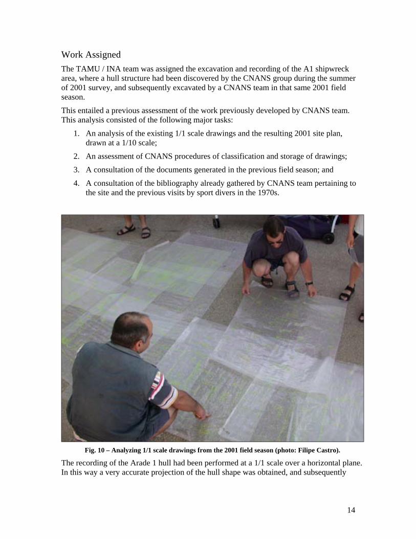
This entailed a previous assessment of the work previously developed by CNANS team. This analysis consisted of the following major tasks:
1. An analysis of the existing 1/1 scale drawings and the resulting 2001 site plan, drawn at a 1/10 scale;
2. An assessment of CNANS procedures of classification and storage of drawings;
3. A consultation of the documents generated in the previous field season; and
4. A consultation of the bibliography already gathered by CNANS team pertaining to the site and the previous visits by sport divers in the 1970s.
Fig. 10 – Analyzing 1/1 scale drawings from the 2001 field season (photo: Filipe Castro).
The recording of the Arade 1 hull had been performed at a 1/1 scale over a horizontal plane. In this way a very accurate projection of the hull shape was obtained, and subsequently

15
reduced into a 1/10 scale (Fig. 11).
Fig. 11 – 2001 hull plan (Drawing: CNANS).
However, the ship’s hull had been only partially recorded in this way during the previous year for lack of time. The remaining portion of the hull – a longitudinal slice about 1 m wide running over the keel – had been recorded over a plastic sheet simply stretched over the shipwreck (Fig. 12).
Fig. 12 – The system of recording used in 2001 (photo: CNANS).

16
The consultation of all the documentation gathered in the previous year was essential for the understanding of the site geomorphology and history. In 2000 and 2001 CNANS and GEO had gathered a collection of rare papers and reports pertaining to the story of the Arade River estuary and the dredging works performed during the 20th century.
All doubts and questions that stemmed from the study of these documents were quickly answered by the 2001 team. Particular useful was the information supplied by the members of the local teams, namely Alberto Machado from GEO and José Sousa from the IPSIS Project (Fig. 13).
Fig. 13 – Carlos Machado (left) and José Sousa (right) (photo: Filipe Castro).
Once in the water, it became clear that the 1/10 scale drawing was very accurate in spite of having been done from two different sources: the 1/1 rigorous projections on the horizontal Plexiglas, and the long plastic sheet stretched over the inside of the hull.
However, this drawing was a projection of the hull plan on a horizontal surface, and for the reconstruction of the hull we needed a full size drawing, a projection of the plan at a plane parallel to the keel.
Given the small dimensions of this ship it was decided to work at a 1/5 scale. For that matter the 1/10 scale hull plan from 2001 was enlarged in a scanner, and divided into small
17
squares, which were checked (scantlings and number and position of fastenings) against the shipwreck.
The recording process entailed the following phases:
1. Removal of the protecting layer of sandbags and sediment, excavating and cleaning the hull.
2. Positioning of the datum points previously implanted (in 2001) around a 10 x 10 m area with the WEB program;
3. Verification of the 1/5 drawing dimensions and number and position of the fastenings;
4. Recording perpendicular sections every third frame and longitudinal sections along the keel axis;
5. Disassembly of the ceiling planking;
6. Recording the timbers underneath the ceiling at a 1/1 scale, which was reduced to a 1/10 scale over a 10 x 10 cm grid, transposed to metric system engineering paper.
7. Recording perpendicular sections on top of every frame;
8. Positioning the tips of six frames relatively to the 10 x 10 m square with the WEB program.
As mentioned above, the closure of this season was carried out by a team from CNANS, who re-covered the shipwreck after the Texas A&M team left.

18
II - The A1 (Arade 1) Shipwreck
Introduction The shipwreck designated A1 by CNANS / GEO team in 2001 was found nearby the area where the shipwreck Arade 1 was sighted for a short period in 1970, during the dredging works described in the Volume 1 – The Site – of this report. It was partially excavated and recorded during that summer’s field season.
The account of the captain of the Dutch dredge Mark suggested that in 1970 the Arade 1 vessel was exposed on the embankment created by the dredge and, while projecting outside the embankment full of sediment, shattered when was touched by the dredge. It may have broke into two parts. The projecting part slid along the embankment and may have been immediately buried by the falling sediment, since it was not seen in 1970.
A reconstruction of the bottom of the river in this area shows a steep embankment with a slope around 1/2 in 1970, after the dredging operations (Fig.14), and a much smoother slope in 1997, when the latest cartography of this area was made (Fig.15). We must keep in mind, however, that the slope created by the dredge during its work was 1/6, much steeper than the 1/2 slope found after the Autumn of 1970, when the cartography was made.
Should the projecting half of the Arade 1 shipwreck be in a somehow cohesive form, it was certainly covered by several meters of sediment in 1970.
Fig. 14 – Bottom at the Arade 1 site in 1970
(Pedro Caleja CNANS). Fig. 15 – Bottom at the Arade 1 site in 1997
(Pedro caleja CNANS).
As to the upper half of the Arade 1 shipwreck, it was reported covered with a thin layer of sediment – between 50 cm and 1 m – a few weeks after the visit of the CPAS team.1
One of the two tasks of the INA / Texas A&M University team was to assess whether or not the A1 ship was the Arade 1 of 1970, and if so, how much of it was preserved. The other was to carry out a full recording of its hull.
1 Dra. Margarida Farrajota personal communication.

19
The A1 Hull As mentioned above, in 2001 part of the A1 hull structure was exposed and recorded at a 1/1 scale. Most of the ship’s hull was drawn on 1 x 1 m plexiglas slates, in horizontal projection. The drawings obtained were then assembled in larger sheets of transparent plastic and then reduced over a grid into a 1/10 scale drawing (Fig. 11).
However, for lack of time, the portion of the hull over the keel axis was recorded directly over a sheet of plastic nailed to the structure (Fig. 16).
Fig. 16 – Preliminary recording on plastic sheet in 2001 (Photo: CNANS).
A series of pictures – excellent, when the general visibility is considered – were taken by Portuguese Navy Capt. Augusto Salgado, who is at the same time a navy officer, a historian, a skilled photographer, and a long time friend and collaborator of CNANS.
As it was uncovered during the 2001 field season, the A1 hull remains comprised part of a keel, one post, 18 frames, four ceiling strakes, two hull strakes on port side, and eight on starboard side. The hull was clearly broken around amidships, and only half was preserved (Fig.11).
In order to answer the first two questions stated above, regarding the possible identification of A1 as the Arade 1 shipwreck of 1970, and the evaluation of the extension of the hull remains preserved, the 2002 field season was developed in three phases:
1. The first phase consisted of a rather quick cleaning operation, which entailed the removal of the layer of sandbags and plastic cover that protected the hull remains during the winter, and of a repair of the 10 x 10 m square that had been positioned around the area in 2001. This square was marked by a series of iron spikes tagged according to its position on the perimeter, and connected by a nylon cable and a red and white tape. As in the previous year, these spikes revealed to be very useful, given the low visibility of the site – inside the river mouth – for the orientation of the
20
divers. On the second phase of the work the spikes mentioned above were used as datum points to position the hull and artifacts lying within the 10 x 10 m square where the excavation was carried out.
2. The second phase consisted of the positioning of all archaeological features inside the 100 m2 area. The mapping was performed at a 1:10 scale with the help of the WEB computer program. The positioning of the hull was not difficult once we established a number of points that could be accurately positioned on the 2001 drawing, and identified in the shipwreck in situ, such as treenails and iron bolt concretions. The extremities of the timbers were damaged during the winter by wood boring worms in spite of all the protection measures taken by CNANS before closing the field season in September 2001. In fact, several octopuses – at least four! – found their way under the plastic cover that protected the shipwreck, and established themselves in the spaces between the sandbags that covered the whole wooden structure. This action allowed the entrance of numerous mollusks and worms to the area between the timber upper surfaces and the plastic cover, and provoked a non-negligible destruction of the upper surfaces and extremities of the timbers.
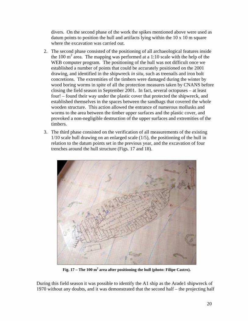
3. The third phase consisted on the verification of all measurements of the existing 1/10 scale hull drawing on an enlarged scale (1/5), the positioning of the hull in relation to the datum points set in the previous year, and the excavation of four trenches around the hull structure (Figs. 17 and 18).
Fig. 17 – The 100 m2 area after positioning the hull (photo: Filipe Castro).
During this field season it was possible to identify the A1 ship as the Arade1 shipwreck of 1970 without any doubts, and it was demonstrated that the second half – the projecting half

21
described by the captain of the dredge Mark – is preserved, buried in the sediment nearby. The portion of the hull excavated and partially recorded in 2001 was tentatively identified as the bow of this vessel, because of the gentle curvature of the post, and because no remains of any steering device – rudder, gudgeons or pintles – were found anywhere near.
Fig. 18 – The 100 m2 area with the position of the trenches.
Around July 15, once the first part of this third phase was finished – the verification of scantlings and fastening holes – the TAMU / INA team started the excavation of the four trenches defined within the 100 m2 working area (Fig. 18).
Trenches 1, 2 and 4 yielded a small number of artifacts, some rigging elements, a few loose timbers, and unidentified concretions. These have greatly contributed to the understanding of the site, and suggest a late 16th century date for the A1 shipwreck. The most interesting find occurred however on trench 3, where a second portion of this hull, showing a clear fracture area, plunged at a 45º degree slope into the sediments.
The portion of the hull found in trench 3 was recorded in a sketchy way for lack of time, and covered with sediment to be studied as soon as the full recording of the portion of the hull already exposed will be completed.
However, it contributed decisively to the identification of A1 as the Arade 1 shipwreck, mostly due to the details preserved, such as the filler pieces photographed in 1970 (see Volume 1 of this report – The Site).

22
Fig.
19
– Pl
an o
f the
hul
l rem
ains
aft
er th
e 20
02 fi
eld
seas
on.
23
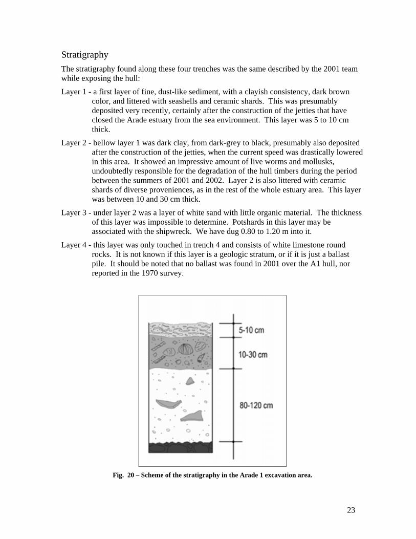
Stratigraphy The stratigraphy found along these four trenches was the same described by the 2001 team while exposing the hull:
Layer 1 - a first layer of fine, dust-like sediment, with a clayish consistency, dark brown color, and littered with seashells and ceramic shards. This was presumably deposited very recently, certainly after the construction of the jetties that have closed the Arade estuary from the sea environment. This layer was 5 to 10 cm thick.
Layer 2 - bellow layer 1 was dark clay, from dark-grey to black, presumably also deposited after the construction of the jetties, when the current speed was drastically lowered in this area. It showed an impressive amount of live worms and mollusks, undoubtedly responsible for the degradation of the hull timbers during the period between the summers of 2001 and 2002. Layer 2 is also littered with ceramic shards of diverse proveniences, as in the rest of the whole estuary area. This layer was between 10 and 30 cm thick.
Layer 3 - under layer 2 was a layer of white sand with little organic material. The thickness of this layer was impossible to determine. Potshards in this layer may be associated with the shipwreck. We have dug 0.80 to 1.20 m into it.
Layer 4 - this layer was only touched in trench 4 and consists of white limestone round rocks. It is not known if this layer is a geologic stratum, or if it is just a ballast pile. It should be noted that no ballast was found in 2001 over the A1 hull, nor reported in the 1970 survey.
Fig. 20 – Scheme of the stratigraphy in the Arade 1 excavation area.

24
Trench 1 Trench 1 was excavated to a depth of around 50 cm along the southeast side of the iron gun found on the eastern corner of the 10 x 10 m square (Fig.18).
The artifacts found in this trench are described in the Volume 3 of this report. They consisted mainly of potshards of various proveniences, as it is frequent in the Arade estuary, and encompassed a few fragments of a Spanish olive jar.
Trench 2 Trench 2 was dug to northwest of the iron gun and extended to west, in the direction of the presumed bow of the vessel. This trench was extended into the west in order to fully expose a loose ship timber (A1-10) whose tip was found within its primary area.
Fig.21 – Timber A1-10 (photo: Alberto Machado).
Fig. 22 - Olive jar A1-30 (photos: Filipe Castro).
25
In this trench two large concretions were found, as well as a large number of potshards of different natures, and a complete Spanish olive jar. Shards of at least another olive jar were found in the area where this trench joined trench 1, under the muzzle of the iron gun, and concreted to the large concretion, which received number A1-12 (see Volume 3 - Artifacts).
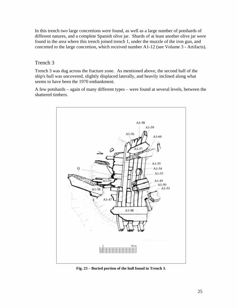
Trench 3 Trench 3 was dug across the fracture zone. As mentioned above, the second half of the ship's hull was uncovered, slightly displaced laterally, and heavily inclined along what seems to have been the 1970 embankment.
A few potshards – again of many different types – were found at several levels, between the shattered timbers.
Fig. 23 – Buried portion of the hull found in Trench 3.

26
Trench 4 Trench 4 was dug along the west side – port side – of the hull remains. Below layer 2 appeared a number of heavily eroded hull planks, displaced and lacking preserved seams.
Below these planks was found a long timber (A1-36) of roughly square section – possibly of pinewood – that showed no fastening holes (Fig. 24). Under this timber there were three deadeyes and remains of rope (Fig. 25).
In the lower strata of layer 3 a few potshards were found, immediately above layer 4.
Fig. 24 – Timber A1-36, found partially under the port side of the hull
(photo: Alberto Machado).
Three heart blocks – in Portuguese sapatas dentadas – were found immediately below timber A1-36, laying over archaeological layer no. 4, together with remains of rope (Figs. 19 and 25).
Fig. 25 – Heart block A1-94 (photos: Filipe Castro).

27
The Hull The upper portion of the A1 shipwreck was fully recorded in plan, and several transversal sections were taken along the runs of the forward faces of the floor timbers.
The ceiling planking was disassembled, and a second map was made of the upper surface of the framing. Some interesting features were observed, such as the presence of fore-and-aft treenails running through three timbers at several places. However, only a full excavation and disassembling will show eventual patterns that will allow a discussion of the construction sequence and conception methods.
Fig. 26 – Hull remains.
Fig. 27 – Timber numbers.
28
Scantlings After the last field season the remains of the upper hull consisted of: Keel - one section, as far as it could be
observed @ C10/C11 level. Sided - 15.5 cm (top); 11cm (bottom). Molded – 13.5 cm. Preserved length – 6.05 m Scarves – Not observed.
Stem post - one section. Sided - 14.5 cm (top); 9.5 cm (bottom). Molded – 13.5 cm Preserved length – 1.49 m. Scarves – Not observed.
Apron – Not fully measured. Sided - 14.5 cm (top).
Floors – fairly well shaped. Sided – Average 17.6 cm Molded – 16 to 17 cm
Futtocks - roughly shaped. First and second futtocks were preserved.
Sided – Average 18 cm. Molded – 16 to 17 cm.
Room and space - irregular. Around 42 cm between C1 and C8. Around 29 cm between C9 and C18.
Ceiling planking (fixed) - Carefully shaped and laid. Linked through flat horizontal scarves.
Thickness – 6 cm. Width – 23 to 27 cm. Max length preserved – 3.28 m (TN3A). Scarves – Flat horizontal, 50 to 60 cm long.
Ceiling planking (floating) – Carefully shaped and laid.
Thickness – 5 cm. Width – Variable. Min. 7 cm; Max. 29 cm.
Filler pieces – Carefully shaped and laid. Thickness – 5 cm. Width – Variable (=space between floors). Length – Around 18 cm.
Hull planking – Carefully shaped and laid. Thickness – 5 cm. Width – Consistently 28 cm. Max preserved length – Not recorded.
Fastenings – Both treenails and iron nails; remains of two bolts.
Keel/Stempost - Not recorded; Floors/Keel - Treenails, Ø = 3 cm; Floors/Futtocks - Treenails, Ø = 3 cm; Keel/Keelson(?) - Iron bolts, Ø = 3.2 cm; Planking/Frames - Iron nails, □ = 8 mm;
treenails, Ø = 3 cm. Ceiling/Frames - Iron nails, □ = 8 mm;
treenails, Ø = 3 cm.
29
Description of the upper portion of the hull The upper portion of the hull extended over an area 7 m long and about 3 m wide. Keel, floor timbers, futtocks, hull and ceiling planking were preserved, together with a concretion that seems to include part of the lower end of a ship’s pump.
Follows a short description of each one of the hull elements which is intended, at this phase of the project, more as a structuring approach and an inventory of missing data than as a comprehensive description of the hull parts observed and recorded.
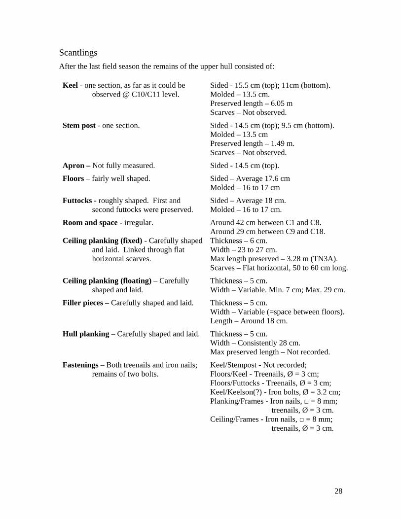
Keel The keel was preserved along an extension of 6.05 m on the upper portion of the shipwreck, and at least 1 m on its lower portion.
Its section was observed both at the fracture section and between floor timbers C10 and C11. In both places it presented a “T” shaped section with a trapezoidal rectangular body (Fig. 29).
Fig. 28 – Keel section between floor timbers C10 and C11.
Fig. 29 – Keel between floor timbers C10 and C11 (photo: Alberto Machado).
30
Towards the post the keel presented a slightly smaller sided dimension, around 15.5 cm. This may signify that the keel section varies along its length, and that the protruding notches disappear as the angle of entry of the garboards gets steeper.
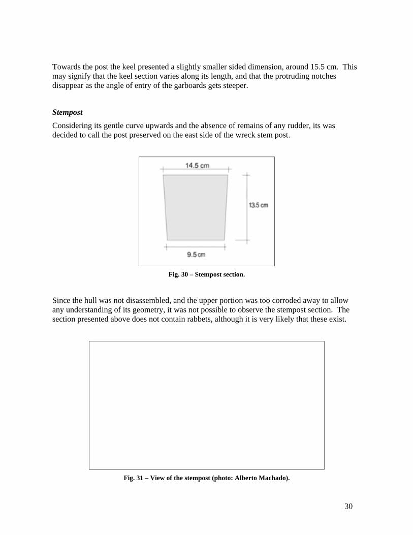
Stempost Considering its gentle curve upwards and the absence of remains of any rudder, its was decided to call the post preserved on the east side of the wreck stem post.
Fig. 30 – Stempost section.
Since the hull was not disassembled, and the upper portion was too corroded away to allow any understanding of its geometry, it was not possible to observe the stempost section. The section presented above does not contain rabbets, although it is very likely that these exist.
Fig. 31 – View of the stempost (photo: Alberto Machado).

31
It is possible that it was fastened to the keel with a flat vertical scarf. Again, only the disassembly of what seems like an apron standing over the forward most section of the keel and stempost will allow us to see it.
Apron Above the stempost laid an apron, badly eroded, with a trapezoidal section, fastened to the stempost with iron nails.
Fig. 32 – Apron (photo: Filipe Castro).
Keelson or Maststep There was no trace of a keelson. In fact, the floating ceiling makes a strong case against the existence of a full keelson and I am inclined to think that the “keelson” recorded in 1970 by Jorge Albuquerque was a mast step (Figs. 32 and 33).
As mentioned above, two iron concretions between frames C10 and C11, and frames C14 and C15 shows that this maststep was fastened to the keel with iron bolts 3.2 cm in diameter.
Judging by Mr. Albuquerque’s scheme this was a solid maststep, about 33 cm sided and 33 cm molded at the mortise section and tapering in its molding dimensions towards the stern of the vessel. According to this drawing it seems that this maststep was protruding 4.72 m out of the embankment.

32
Fig. 33 – Maststep as it was found in 1970 after Jorge Albuquerque’s drawing.
The captain of the dredge Mark, which destroyed this vessel in 1970, told the team of divers that as he dredged the bottom away from the shipwreck it came out of the embankment, (what we think to have been) its stern projecting from the wall. Then he came nearer and touched it with the dredge, presumably sailing in the direction South-North, and it shattered, as it was full of sediments and had no support underneath.
Falling mud quickly covered the lower portion of the hull, as the embankment adjusted its slope to the natural cohesion of the sediment. At least the 1970 teams who visited the site did not report it.
It is possible that this section of the maststep was lost forever, carried away by the current, and only further excavation of the lower portion of the hull will possibly give any information on this subject.
Frames A total of 18 frames were partially preserved over the upper portion of the keel, to which we must add a 19th position marked over the stempost by the remains of a treenail on the planking. Another three frames were exposed on the buried portion of the hull (Fig. 34).
In spite of the fact that we did not observe the pattern in which floors and futtocks were assembled, it was assumed in this study that the futtock corresponding to each floor timber is the one that stands east of it. In other words, each floor was associated to the futtocks that stand against its forward face for the purpose of this study.

33
Fig 34 – Frame numbers after the 2002 field season.
The scantlings of the floor timbers and first futtocks are indicated next page, on Table I. The molded dimensions noted on this schematic representation of the preserved frames are all equal to 16 cm. This does not translate the reality, but an average value for the distance between the upper surface of the hull planking and the lower surface of the ceiling planking, consistently between 16 and 17 cm. In fact, most floors and futtocks showed quite irregular upper surfaces, and a few had been patched to level the surface that received the ceiling planking (Fig. 38).
At this stage of the study there are more questions than answers regarding the composition and geometry of the Arade 1’s frames. We do not know if there is a central portion of the hull with pre-designed and pre-assembled frames. However, both the room and space, and the timber scantlings suggest that frames C9 to C18, and C20 to C22 have been fashioned with more care and mounted over the keel with a more consistent pattern, spaced apart around 20 cm.
As to frames C1 to C8, they seem to have been less carefully shaped, and placed over the keel at less regular intervals, as show on Table II below.
Only four, badly eroded, second futtocks – probably top timbers – have survived in the upper portion of the hull.
Below is a broad description of each one of the timber types that formed the Arade 1 frames: floor timbers, first futtocks, and second futtocks.

34
Table I
Floor Timbers and 1st Futtocks – Scantlings
Floor C0 – Not preserved. 1st Futtock B1B – Not preserved. 1st Futtock B1E – Not preserved Floor C1 – molded 8 cm*; sided 16 cm. 1st Futtock B2B – Not preserved. 1st Futtock B2E – molded 12 cm*; sided 20 cm. Floor C2 – molded 16 cm; sided 18 cm. 1st Futtock B3B – molded 16 cm; sided 16 cm. 1st Futtock B3E – molded 16 cm; sided 21 cm. Floor C3 – molded 16 cm; sided 23 cm. 1st Futtock B4B – molded 16 cm; sided 16 cm. 1st Futtock B4E – molded 16 cm; sided 18.5 cm. Floor C4 – molded 16 cm; sided 22 cm. 1st Futtock B5B – molded 16 cm; sided 16 cm. 1st Futtock B5E – molded 16 cm; sided 19 cm. Floor C5 – molded 16 cm; sided 25 cm. 1st Futtock B6B – Not preserved. 1st Futtock B6E – molded 16 cm; sided 19 cm. Floor C6 – molded 16 cm; sided 23 cm. Top timber Ap6E → 1st Futtock B7B – molded 16 cm; sided 16 cm. 1st Futtock B7E – molded 16 cm; sided 22.5 cm. Floor C7 – molded 16 cm; sided 20 cm. 1st Futtock B8B – molded 16 cm; sided 16 cm. 1st Futtock B8E – molded 16 cm; sided 16.5 cm. Floor C8 – molded 16 cm; sided 20 cm. Top timber Ap8E → 1st Futtock B9B – molded 16 cm; sided 16 cm. 1st Futtock B9E – molded 16 cm; sided 18 cm. Floor C9 – molded 16 cm; sided 14 cm. 1st Futtock B10B – Not preserved. 1st Futtock B10E – molded 16 cm; sided 18 cm. Floor C10 – molded 16 cm; sided 15 cm. 1st Futtock B11B – Not preserved. 1st Futtock B11E – molded 16 cm; sided 19 cm. Floor C11 – molded 16 cm; sided 14 cm. Top timber Ap11E → 1st Futtock B12B – Not preserved. 1st Futtock B12E – molded 16 cm; sided 15 cm. Floor C12 – molded 16 cm; sided 14 cm. 1st Futtock B13B – Not preserved. 1st Futtock B13E – molded 16 cm; sided 18 cm. Floor C13 – molded 16 cm; sided 16 cm. Top timber Ap13E → 1st Futtock B14B – Not preserved. 1st Futtock B14E – molded 16 cm; sided 17 cm. Floor C14 – molded 16 cm; sided 15 cm. 1st Futtock B15B – Not preserved. 1st Futtock B15E – molded 16 cm; sided 15 cm. Floor C15 – molded 16 cm; sided 15 cm. 1st Futtock B16B – Not preserved. 1st Futtock B16E – molded 16 cm; sided 16 cm. Floor C16 – molded 16 cm; sided 16cm. 1st Futtock B17B – Not preserved. 1st Futtock B17E – molded 16 cm; sided 16 cm. Floor C17 – molded 16 cm; sided 16cm. 1st Futtock B18B – Not preserved. 1st Futtock B18E – molded 12 cm*; sided 16 cm. Floor C18 – molded 16 cm; sided 16cm. 1st Futtock B20B – molded 16 cm; sided 17 cm. 1st Futtock B20E – Not preserved. Floor C20 – molded 16 cm; sided 17 cm. 1st Futtock B21B – molded 16 cm; sided 19 cm. 1st Futtock B21E – molded 16 cm; sided 19 cm. Floor C21 – molded 16 cm; sided 15 cm. 1st Futtock B22B – molded 16 cm; sided 14 cm. 1st Futtock B22E – molded 16 cm; sided 14 cm. Floor C22 – molded 16 cm; sided 17 cm. * Incomplete section.

35
Table II
Spacing Between Frames
Floor timber
Dimension over the keel
Space to previous
frame
Space between frame axis
C0 Not preserved ? C0/C1 ≈ 45 cm C1 16 cm ? C1/C2 = 39 cm C2 18 cm 22 cm C2/C3 = 39.5 cm C3 23 cm 19 cm C3/C4 = 41.5 cm C4 22 cm 19 cm C4/C5 = 40.5 cm C5 25 cm 17 cm C5/C6 = 46 cm C6 23 cm 22 cm C6/C7 = 41.5 cm C7 20 cm 20 cm C7/C8 = 44 cm C8 20 cm 24 cm C8/C9 = 33 cm C9 14 cm 16 cm C9/C10 = 32.5 cm C10 15 cm 18 cm C10/C11 = 34.5 cm C11 14 cm 20 cm C11/C12 = 33 cm C12 14 cm 19 cm C12/C13 = 35 cm C13 16 cm 20 cm C13/C14 = 35.5 cm C14 15 cm 20 cm C14/C15 = 35 cm C15 15 cm 20 cm C15/C16 = 38 cm C16 Not preserved ? C16/C17 = 36 cm C17 Not preserved ? C17/C18 = 35 cm C18 Not preserved ? C18/C19 = ?
–––––– C20 17 cm 17 cm C20/C21 = 35 cm C21 15 cm 19 cm C21/C22 = 30 cm C22 17 cm 14 cm C22/C23 = ?
a) Floor timbers As mentioned above, the Arade 1 floor timbers can be divided into two main groups.
The first, lighter and better shaped, comprises floors C9 to C18 and C20 to C22. These more central floor timbers were spaced roughly 20 cm apart and presented almost square sections 15 cm sided and 16 cm molded. Their lower surfaces seemed smoother and showed better adherence to the hull planking.
The second group of floor timbers comprised the frames localized before floor C9. These floor timbers were placed over the keel at less regular intervals, although the average distance between then – 20 cm – did not vary much from the average distance between central frames – 19.5 cm. However, since these bow frames presented heavier scantlings, the average value of the room and space varied greatly between the first and second group, being 29.4 cm for the
36
central frames, and 42.1 cm for the bow frames.
All floor timbers inspected were fastened to the keel with one or more treenails with the exception of floor C1, which sits on the stempost and was fastened to it with one single iron nail (Table III).
Table III
Fastenings Frames / Keel
Floor Fastening to the keel C1 1 iron nail. C2 1 treenail diagonally inserted from the starboard side. C3 1 treenail diagonally inserted from portside. C4 1 treenail diagonally inserted from portside + 1 iron nail. C5 1 treenail diagonally inserted from portside + 2 iron nails. C6 2 treenails, 1 on each side of the limber hole. C7 3 treenails, 2 to starboard side of the limber hole, 1 to portside. C8 2 treenails, 1 on each side of the limber hole. C9 3 treenails, 1 to starboard side of the limber hole, 2 to portside. C10 1 treenail to starboard side of the limber hole. C11 2 treenails, 1 on each side of the limber hole. C12 1 treenail to portside of the limber hole. C13 2 treenails, 1 on each side of the limber hole. C14 2 treenails, 1 on each side of the limber hole. C15 2 treenails, 1 on each side of the limber hole. C16 Possibly 2 treenails, 1 on each side of the limber hole. C17 Possibly 2 treenails, 1 on each side of the limber hole. C18 Not preserved.
C20 2 treenails, 1 on each side of the limber hole. C21 2 treenails, 1 on each side of the limber hole. C22 2 treenails, 1 on each side of the limber hole.
All floor timbers had trapezoidal limber holes 5 cm high, 6 to 8 cm on their basis, and 4 to 5 cm on their tops (Figs. 33 and 34).
All seemed to have been cut of oak trees with diameters smaller than 20 cm.
Three of the bow floor timbers – numbers C3, C4, and C5 – presented a fore and aft groove of unknown function in their upper surfaces, roughly over the keel (Fig. 37).
Two of the floor timbers on the upper hull – C11 and C12 – had been leveled with patches to receive the ceiling planking (Fig. 38). This procedure was probably repeated on the lower portion of the hull, where floors C20 and C21 also had small planks attached. However, because the ceiling planking was not preserved, it is possible that these patches, on floors C20 and C21, were used to level some kind of floating bilge ceiling.

37
Fig. 35 – Floor timber photographed in 1970 showing a typical limber hole (photo: Ricardo Costa).
Fig. 36 – Limber holes’ dimensions (from the dive log).
Fig. 37 – Aspect of the upper surfaces of floor timbers (photo: Filipe Castro).
38
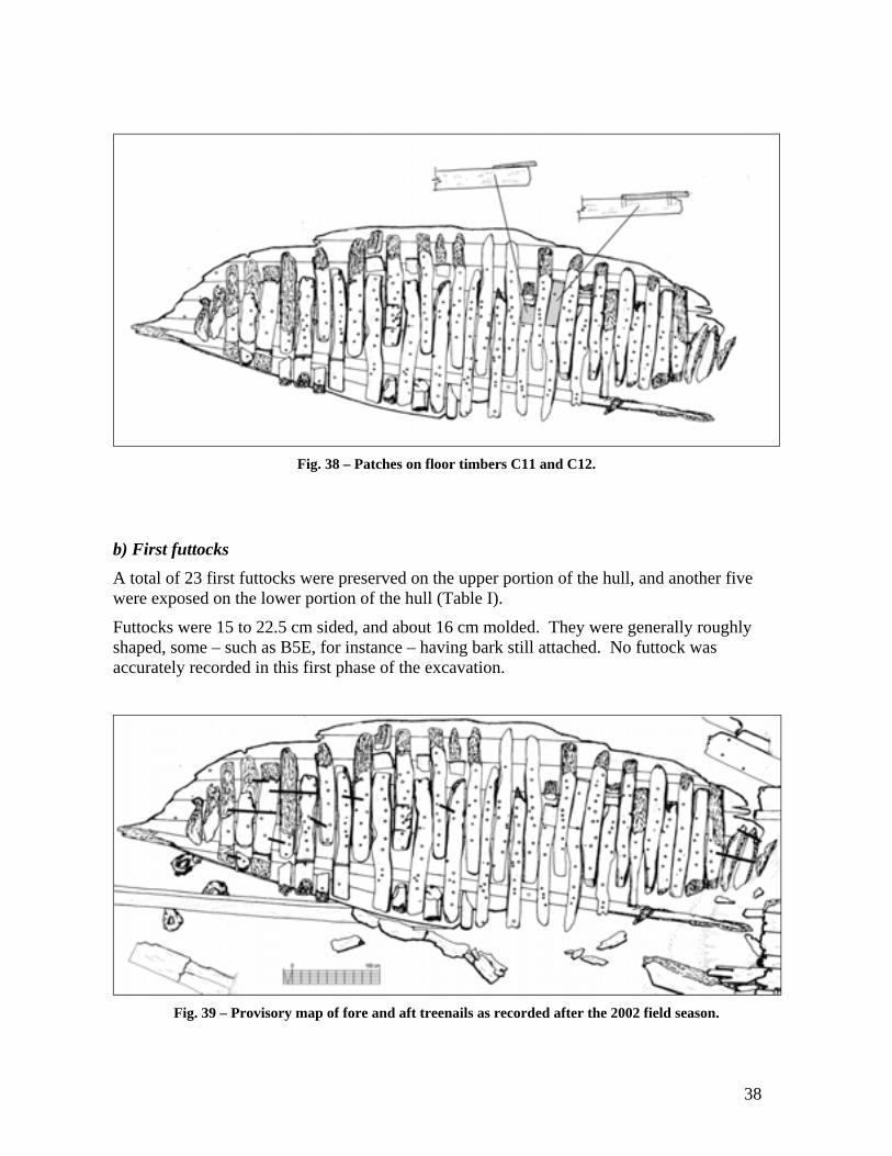
Fig. 38 – Patches on floor timbers C11 and C12.
b) First futtocks A total of 23 first futtocks were preserved on the upper portion of the hull, and another five were exposed on the lower portion of the hull (Table I).
Futtocks were 15 to 22.5 cm sided, and about 16 cm molded. They were generally roughly shaped, some – such as B5E, for instance – having bark still attached. No futtock was accurately recorded in this first phase of the excavation.
Fig. 39 – Provisory map of fore and aft treenails as recorded after the 2002 field season.

39
Several first futtocks were fastened to the floors. However, since no futtocks were disassembled during the 2002 field season, the fastening pattern is not yet known. One interesting feature raised interesting questions: it seems that, at least in four places, fore and aft treenails fasten three timbers at the same time (Fig. 39).
If this is true, it will be interesting to assess the directions in which the holes were augured and the treenails introduced, because that will yield precious clues to our interpretation of the construction sequence.
c) Second futtocks Only four, badly eroded second futtocks – probably top timbers – were preserved on the starboard side of the Arade 1 shipwreck.
These were between 14 and 17 cm sided. It is impossible to know their molded dimensions, since none was preserved along an extension over 25 cm. The best-preserved – Ap6 – was preserved to a maximum of 9 cm high, surely less than its full original maximum molded dimension.
Fig. 40 – Sketches of Ap6E, Ap11E and Ap13E showing how badly preserved were the second futtocks.
Only further work on the Arade 1 structure will allow us a better view at these frames. In the mean time, since the 2002 field season was a Texas A&M Nautical Archaeology Program summer school and all students had to practice timber recording under water as part of the curriculum of the course, a number of profiles were taken of the upper faces of the first futtocks, both with offsets and with a digital inclinometer.
A complete profile of each frame was taken with offsets from a horizontal bar, while a second team took profiles of frames numbers 2, 4, 8, 12, 14 and 15 as a redundant measure. Then another group of students took another complete set of profiles with a digital inclinometer and yet another team took a complete set of sections of the central planking, between C1 and C10, where it was exposed and preserved.
40
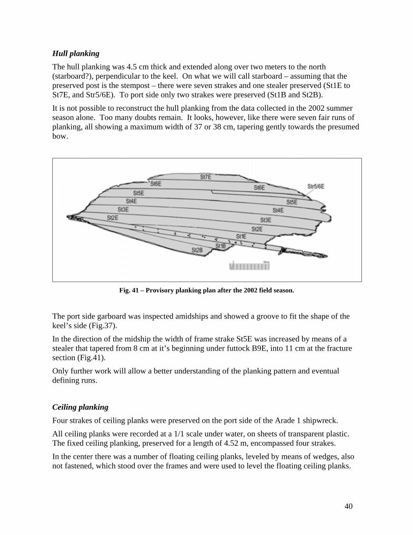
Hull planking The hull planking was 4.5 cm thick and extended along over two meters to the north (starboard?), perpendicular to the keel. On what we will call starboard – assuming that the preserved post is the stempost – there were seven strakes and one stealer preserved (St1E to St7E, and Str5/6E). To port side only two strakes were preserved (St1B and St2B).
It is not possible to reconstruct the hull planking from the data collected in the 2002 summer season alone. Too many doubts remain. It looks, however, like there were seven fair runs of planking, all showing a maximum width of 37 or 38 cm, tapering gently towards the presumed bow.
Fig. 41 – Provisory planking plan after the 2002 field season.
The port side garboard was inspected amidships and showed a groove to fit the shape of the keel’s side (Fig.37).
In the direction of the midship the width of frame strake St5E was increased by means of a stealer that tapered from 8 cm at it’s beginning under futtock B9E, into 11 cm at the fracture section (Fig.41).
Only further work will allow a better understanding of the planking pattern and eventual defining runs.
Ceiling planking Four strakes of ceiling planks were preserved on the port side of the Arade 1 shipwreck.
All ceiling planks were recorded at a 1/1 scale under water, on sheets of transparent plastic. The fixed ceiling planking, preserved for a length of 4.52 m, encompassed four strakes.
In the center there was a number of floating ceiling planks, leveled by means of wedges, also not fastened, which stood over the frames and were used to level the floating ceiling planks.

41
Fig. 42 – Arade 1 ceiling planking.
All ceiling planks were 6 cm thick and 28 to 29 cm wide at their maximum width points. Their average lengths cannot be estimated, because none was preserved in its entirety. The longest – TN4 – was preserved for 3.60 m.
Fig. 43 – Ceiling plank TN2A (photo: Filipe Castro).
Strakes 1, 2 and 3 were composed of two planks each, scarved together with flat horizontal scarves originally around 40 cm long.
Fig. 44 – Matting in a picture taken in 1970 (photo: Fernando Pina).

42
There was no apparent fastening pattern. Some planks were fastened to the frames with small nails whose heads had long eroded away. This may suggest either some kind of provisory fastening, or the nailing of some kind of matting over the ceiling planking. This matting was photographed in 1970 and was still preserved in an iron concretion of one of these nails Figs. 42 and 43).
Fig. 45 – Remains of matting preserved in an iron concretion (photo: Augusto Salgado).
Under the mat there were two layers of dunnage, clearly apparent in the 1970 pictures but completely gone by 2002.
Fig. 46 – Dunnage photographed in 1970 (photo: Fernando Pina).

43
Filler pieces Filler pieces are a diagnostic feature of this shipwreck. They show clearly in the 1970 pictures, and they are typical of Iberian ships in this period.
In some of the 1970 pictures it seems that the upper ceiling strake is notched and covers the space in front of the first futtocks (Figs. 46 and 47). However, the filler pieces preserved on the lower portion of the hull show clearly that they have been cut in two different sizes, to fit in front, and between the first futtocks.
Fig. 47 – Scheme of the filler pieces’ arrangement.
Fig. 48 – Filler pieces in 1970 (photo: Ricardo Costa).
44
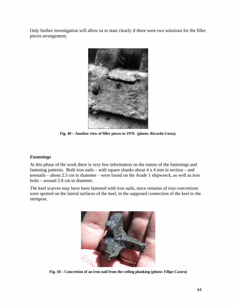
Only further investigation will allow us to state clearly if there were two solutions for the filler pieces arrangement.
Fig. 49 – Another view of filler pieces in 1970. (photo: Ricardo Costa).
Fastenings At this phase of the work there is very few information on the nature of the fastenings and fastening patterns. Both iron nails – with square shanks about 4 x 4 mm in section – and treenails – about 2.5 cm in diameter – were found on the Arade 1 shipwreck, as well as iron bolts – around 2.8 cm in diameter.
The keel scarves may have been fastened with iron nails, since remains of iron concretions were spotted on the lateral surfaces of the keel, in the supposed connection of the keel to the stempost.
Fig. 50 – Concretion of an iron nail from the ceiling planking (photo: Filipe Castro)
45
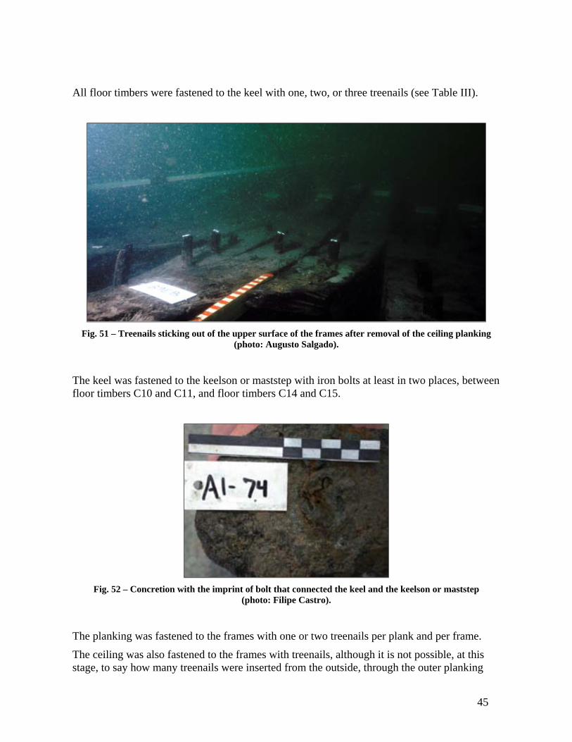
All floor timbers were fastened to the keel with one, two, or three treenails (see Table III).
Fig. 51 – Treenails sticking out of the upper surface of the frames after removal of the ceiling planking
(photo: Augusto Salgado).
The keel was fastened to the keelson or maststep with iron bolts at least in two places, between floor timbers C10 and C11, and floor timbers C14 and C15.
Fig. 52 – Concretion with the imprint of bolt that connected the keel and the keelson or maststep
(photo: Filipe Castro).
The planking was fastened to the frames with one or two treenails per plank and per frame.
The ceiling was also fastened to the frames with treenails, although it is not possible, at this stage, to say how many treenails were inserted from the outside, through the outer planking

46
and frames, and how many – if any – were inserted from the inside.
As mentioned before, it seems that some fore and aft treenails run through more than two timbers (Figs. 39 and 53).
Fig. 53 – Treenail running through timbers C3/B3E/C2 (photo: Filipe Castro).
Caulking No traces of caulking have been found so far. Hopefully they will be retrieved as we proceed to the disassembly of the planking next year.
Some timbers showed a white coating on the inside. Its nature is so far unknown.
Fig. 54 – White coating on one of the futtocks’ inner extremities (photo: Gustavo de Carvalho).

47
Pump A concretion with what is thought to be the bottom of a ship’s pump was found during the 2001 field season. It was displaced and its shape is not easily understandable. It is asymmetrical and its lower sides show the imprint of wood grain.
Given the fact that we have found the pump sump carved on the lower portion of the hull, between floor timber C21 and C22, it seems that the pump shaft was displaced and its lead bottom involved in the iron concretion that formed on the bottom of the hull after the collapse of some of some of its inner structure, such as a bulkhead or the walls of the pump well. The concretion involving the bottom of the pump is trapezoidal in shape and bears the marks of wood grain on both sides, suggesting that it was formed between two collapsed planks.
Fig. 55 – Pump sump (photo: Augusto Salgado)
Fig. 56 – Concretion of the pump (photo: Filipe Castro).

48
Fig.57 – Another view of the concretion of the pump (photo: Filipe Castro)
Hull shape Although there is enough data to try a reconstruction of the hull shape from the profiles taken during the 2002 field season, that effort seems premature at this stage of the project, in view of the amount of data that can be retrieved during the next field season, when a number of frames are scheduled to be disassembled.
Fig. 58 – Mr. Albuquerque’s sketch of 1970.
49
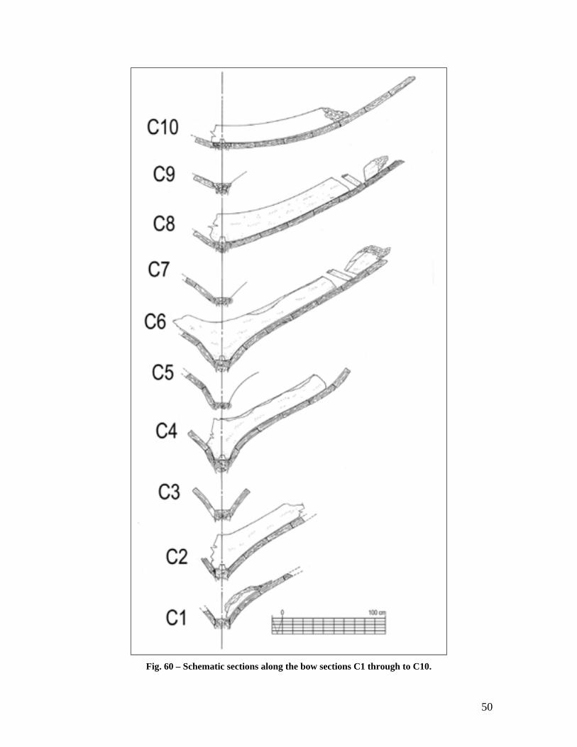
As it is, the existing data shows that the planking at the bow has fallen out slightly – frame C2 must be slightly tilted towards starboard – and that the keel must have been severely misaligned upon breaking in 1970. In fact, the first striking feature when one looks at this vessel is that the frames are not perpendicular to the keel!
The sketch made in 1970 by Mr. Albuquerque may correspond to a section very close to amidships because it shows a fairly flat section (Fig. 58).
The data retrieved during the summer of 2002 shows a hull shape that is compatible with Mr. Albuquerque’s sketch but ends – at floor timber C10 – well before the midship frame.
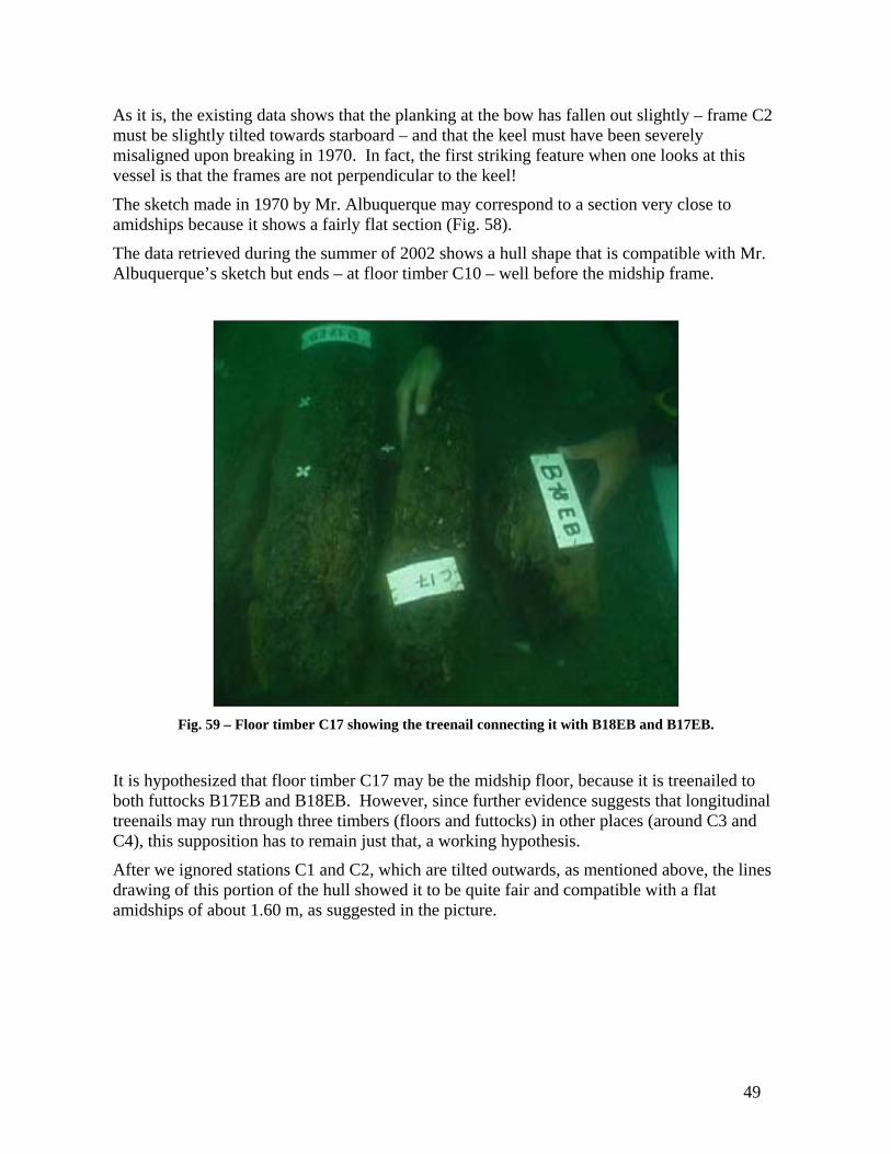
Fig. 59 – Floor timber C17 showing the treenail connecting it with B18EB and B17EB.
It is hypothesized that floor timber C17 may be the midship floor, because it is treenailed to both futtocks B17EB and B18EB. However, since further evidence suggests that longitudinal treenails may run through three timbers (floors and futtocks) in other places (around C3 and C4), this supposition has to remain just that, a working hypothesis.
After we ignored stations C1 and C2, which are tilted outwards, as mentioned above, the lines drawing of this portion of the hull showed it to be quite fair and compatible with a flat amidships of about 1.60 m, as suggested in the picture.
50
Fig. 60 – Schematic sections along the bow sections C1 through to C10.
51
This makes the Arade 1 overall dimensions around 12 to 15 m long, 4 m in beam, 2 to 2.5 m of depth in hold, and 1.6 m of flat amidships.
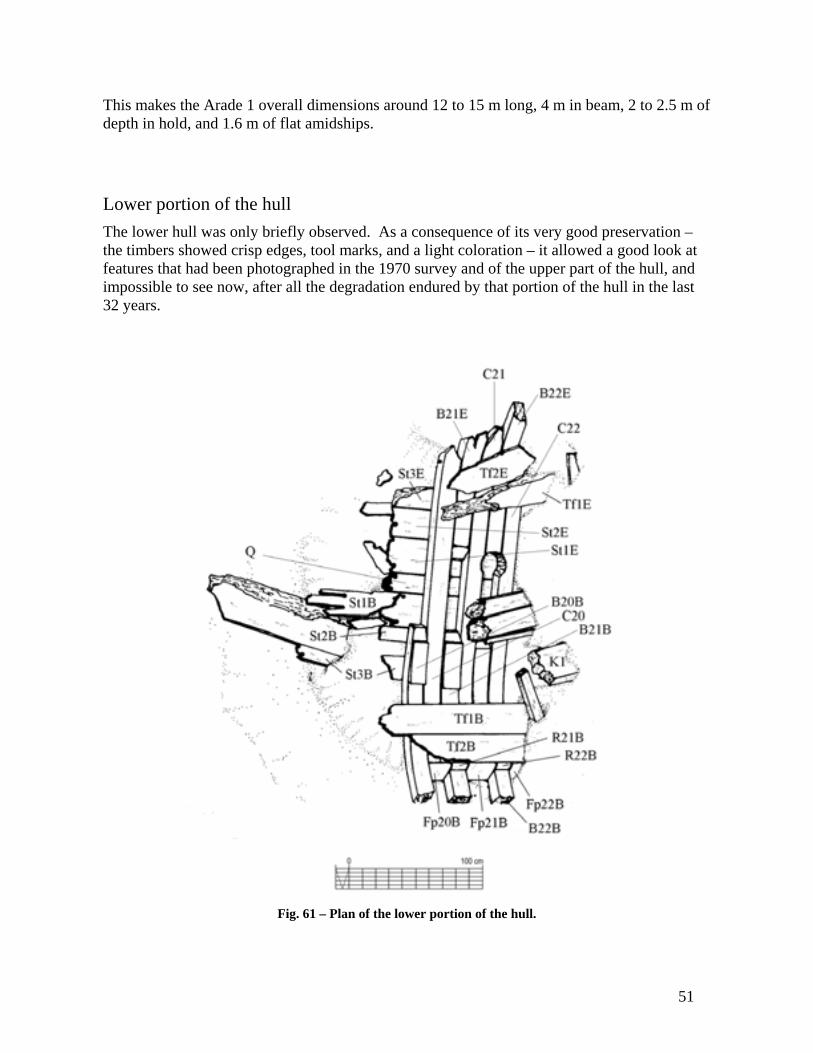
Lower portion of the hull The lower hull was only briefly observed. As a consequence of its very good preservation – the timbers showed crisp edges, tool marks, and a light coloration – it allowed a good look at features that had been photographed in the 1970 survey and of the upper part of the hull, and impossible to see now, after all the degradation endured by that portion of the hull in the last 32 years.
Fig. 61 – Plan of the lower portion of the hull.

52
Maststep As mentioned before, a long portion of a maststep was seen in 1970 (Fig. 33). Part of what may be a remaining portion of that maststep was uncovered on the bottom of Trench 3 before we stop digging. The next field season will certainly allow a better look over this important piece, which was only glanced at in this summer.
It was exposed along less than 30 cm. This end was fractured, and presented a rectangular section 40 cm sided and 12 cm molded.
Fig. 62 – Location of the presumed portion of the maststep found in Trench 3.
Filler pieces As mentioned above, filler pieces had been photographed in 1970, and were found on both the upper and the lower hull. However, since the upper hull filler pieces preserved were few and badly eroded, their shape could only be reconstructed from the perfectly preserved filler pieces found in the lower portion of the hull (see Figs. 47, 48, and 49).
These timbers were 5 cm thick and their width varied according to the sided dimension of the floor timbers and futtocks. They presented dimensions that varied alternately around 5 x 20 cm, and 20 x 20 cm.

53
Fig. 63 – Detail of the filler pieces from the dive log.
Pump well As mentioned above, we found a circular hole carved between floor timbers C21 and C22 that could only be used to house the lower portion of the ship’s pump.
It was roughly 20 cm in diameter and showed marks of the curved chisel that was used to carve it, with a blade around 4 cm wide (see Fig. 55).
Fig. 64 – Location of the pump sump.

54
Scattered timbers
Some timbers were found lying around the upper portion of the hull. The most important were timber fragment A1-10, possibly part of a frame, and timber A1-36, possibly just a spare timber.
Timber fragment A1-10 was found on Trench 2. It measured 107 x 13 x 13 cm and had a mortise on one of its extremities. It was raised and will hopefully be fully drawn and analyzed in order to establish its provenience and structural function.
Fig. 65 – Timber A1-10 (photo: Filipe Castro).
Timber A1-36 was a long pine timber of 18 x 18 cm square section, 4.40 m long, found on Trench 4, underneath the hull, lying above the three dead eyes found on the port side of the shipwreck. Its function is unknown.
Fig. 66 – Timber A1-36 (photo: Alberto Machado).
55
Wood species A sample from the Arade 1 shipwreck was analyzed in the Centro de Investigacao em Paleoecologia Humana of the Instituto Português de Arqueologia, and found to be oak (Quercus faginea Lam.), known in Portuguese as carvalho cerquinho, common in the center and south of Portugal and Spain.
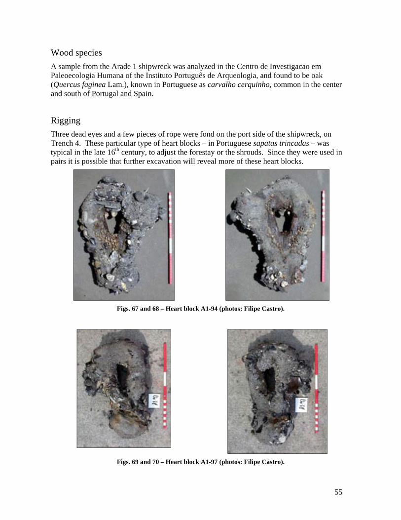
Rigging Three dead eyes and a few pieces of rope were fond on the port side of the shipwreck, on Trench 4. These particular type of heart blocks – in Portuguese sapatas trincadas – was typical in the late 16th century, to adjust the forestay or the shrouds. Since they were used in pairs it is possible that further excavation will reveal more of these heart blocks.
Figs. 67 and 68 – Heart block A1-94 (photos: Filipe Castro).
Figs. 69 and 70 – Heart block A1-97 (photos: Filipe Castro).
56
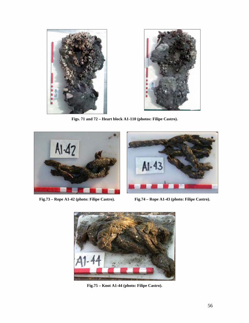
Figs. 71 and 72 – Heart block A1-110 (photos: Filipe Castro).
Fig.73 – Rope A1-42 (photo: Filipe Castro). Fig.74 – Rope A1-43 (photo: Filipe Castro).
Fig.75 – Knot A1-44 (photo: Filipe Castro).

57
Cargo There are very few clues to what the cargo of this vessel may be. We know how carefully laid and sturdy was the ceiling planking, we know that there was a mat over the ceiling planking and that above that mat there were two layers of dunage. But the only object found between the frames a walnut bearing mouse teeth marks, and fully eaten.
Fig. 76 – Walnut showing marks of mice teeth (photo: Filipe Castro).
The round concretions found around the shipwreck can be barrel woops, but so far, and until the concretion A1-21, which was raised, is analyzed and X-rayed it is impossible to say one way or another. And even if these are in fact barrel woops, we still cannot state whether these barrels were related to the cargo, or to the crew’s victuals.
Artifacts The artifact collection found within the 10 x 10 m area defined around the Arade 1 ship is small and poor. A cast iron gun, a pewter plate and a copper cauldron were found during the 2001 field season. An olive jar and three dead-eyes have been found during the 2002 field season. A total of 114 artifacts were raised and catalogued, mostly ceramic shards.
The study of the artifact collection will undoubtedly yield information that will perhaps help identify and date this type of vessel. For the time being only basic conservation is underway, and its study will only be considered in the context of the whole Arade River artifact collection, gathered during the last decades by the local archaeological museum.
58
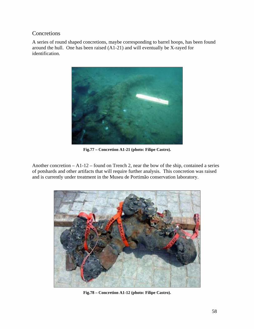
Concretions A series of round shaped concretions, maybe corresponding to barrel hoops, has been found around the hull. One has been raised (A1-21) and will eventually be X-rayed for identification.
Fig.77 – Concretion A1-21 (photo: Filipe Castro).
Another concretion – A1-12 – found on Trench 2, near the bow of the ship, contained a series of potshards and other artifacts that will require further analysis. This concretion was raised and is currently under treatment in the Museu de Portimão conservation laboratory.
Fig.78 – Concretion A1-12 (photo: Filipe Castro).

59
Conclusion There is no doubt that A1 is the Arade 1 shipwreck of 1970:
a) the location of A1 matches the location noted in CPAS' 1970 map;
b) the story of its trove and breakage, as told by the captain of the dredge Mark, matches the pattern in which the hull lays;
c) the size of the hull remains matches the descriptions of 1970 and 1972;
d) the filler pieces found on the lower portion of the hull – uncommon by all standards – look exactly like the ones photographed in 1970;
e) the floor timber photographed in 1970 looks exactly like the ones recorded in 2002, even in smaller details such as the scupper hole;
f) round concretions identical to the ones described in FPAS' 1972 video were found around the shipwreck; and
g) a small portion of the mat photographed in 1970 was found concreted to the ceiling planking.
Some of the artifacts found around the Arade 1 ship suggest a date around the last quarter of the 16th century for its loss. In fact, both the heart blocks and the olive jar are typical of this period, an impression that is reinforced by the presence of a cast iron gun nearby, which could not have been cast much earlier than this period.
The extension of the hull remains suggest an overall length around 15 m, a beam around 5 m, and a depth in hold around 3 or 4 m. These measurements must be confirmed however, and are presented here as mere estimates after preliminary recording.
Although probably Iberian – if we consider the filler pieces that seal the lower area of the bilge above the ceiling planking, between and over the first futtocks, as an almost exclusive Iberian feature – we have no evidence that allows us to state clearly its origin. Very few 16th century hulls have survived from the Iberian shipbuilding family, and there is no typical 16th century Iberian hull, particularly when we consider small craft.
When compared with the irregularity of the floor timbers near the stempost, the midship floors’ crisp and regular appearance suggests a pre-designed central portion of the frames.
The long for-and-aft treenails suggest either that the floors and futtocks were pre-assembled or that they were augured with the frames in place, before the mounting of the planking. However, only a careful and accurate recording of its directions will allow a full understanding of the construction sequence.
All these features raise many interesting questions pertaining to the way the Arade 1 was conceived and built, and make it a very interesting ship, probably unique as an archaeological example of a small trader. In spite of its probably humble origins and the lack of rare artifacts I am convinced that its excavation is well justified in terms of its scientific importance.

60
Next Steps The 2003 summer field season should now focus on a partial disassembly and recording of the upper portion of the hull. Wood samples should be taken for radiocarbon dating. Dendrochronological studies have also been contemplated, although a laboratory has not yet been selected.
The most important features to be examined in the next excavation campaign should be:
1) The keel and garboard geometry;
2) The keel/stempost fastening pattern;
3) The apron shape;
4) The frames’ fastening pattern: floors/futtocks;
5) The planking/frames fastening pattern;
6) The planking runs;
7) The distortion recorded in the keel/frames (not perpendicular);
8) The hull shape – a redundant verification of the shape should be tried by recording the shape of the lower surface of a few floor timbers;
9) The caulking arrangement;
Once the 2003 summer field season projects are fully accomplished, a full inspection of the lower portion of the hull should be attempted, as well as a magnetometer survey in the immediate surroundings of the area, in order to try to find the ship's anchor, which was reported laying nearby in 1970.