figure 3.1 reynolds’ apparatus - marmara...
TRANSCRIPT

Figure 3.1 Reynolds’ apparatus

Figure 3.2 Velocity profiles of laminar and turbulent flows in circular pipes

Figure 3.3 General description of flow in pipes

Figure 3.4 Flow through a horizontal nozzle

Figure 3.5 Total energy and head loss in pipe flow

Figure 3.6 Flow from an elevated water tank

Figure 3.7 Geometry of a circular pipe
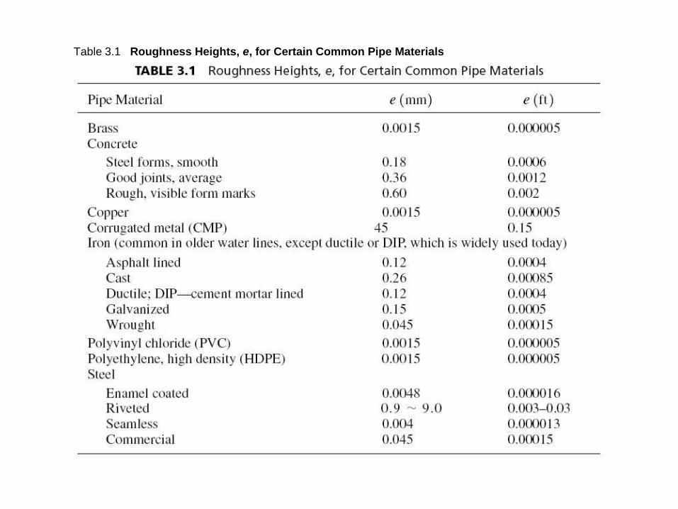
Table 3.1 Roughness Heights, e, for Certain Common Pipe Materials

Figure 3.8 Friction factors for flow in pipes: the Moody diagram. Source: From L. F. Moody,
“Friction factors for pipe flow,” Trans. ASME, vol. 66, 1944.

Table 3.2 Hazen-Williams Coefficient, CHW, for Different Types of Pipes

Table 3.3 Manning’s Roughness Coefficient, n, for Pipe Flows

Table 3.4 Friction Equations Expressed in the Form of hf = KQm

Figure 3.9 Head loss and pressure variation resulting from sudden contraction

Table 3.5 Values of the Coefficient Kc for Sudden Contraction

Figure 3.10 Pipe confusor

Figure 3.11 Coefficient K’c for pipe confusors. Source: From Chigong Wu et al., Hydraulics
(Chengdu, Sichuan, China: The Chengdu University of Science and Technology Press, 1979).

Figure 3.12 Coefficient Ke for pipe entrances

Figure 3.13 Head loss from sudden expansion

Figure 3.14 Pipe diffusor

Figure 3.15 Exit (discharge) head loss
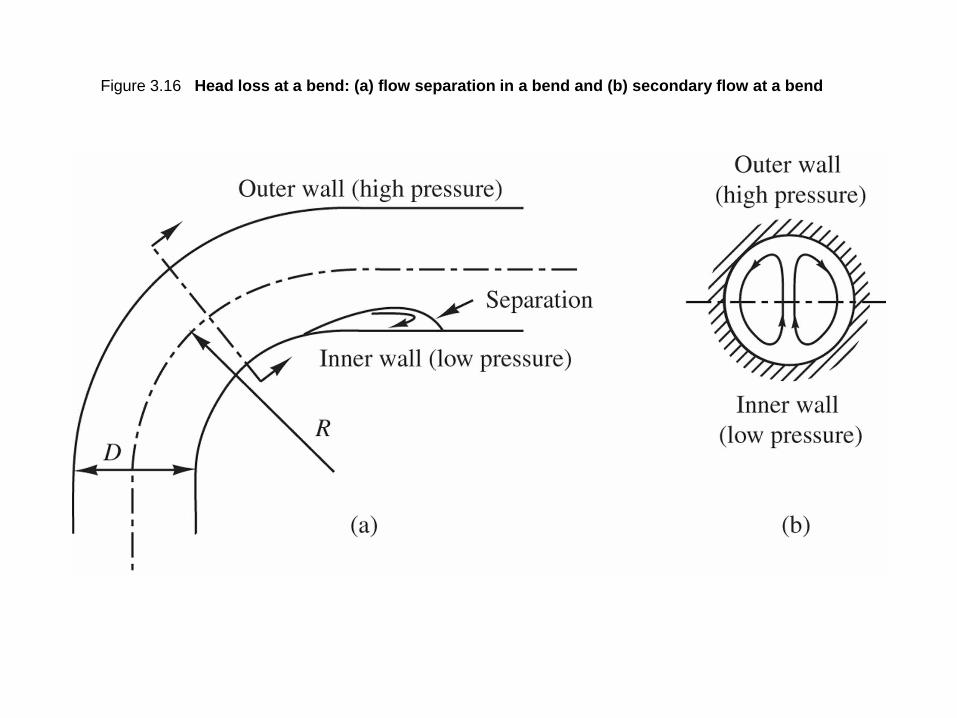
Figure 3.16 Head loss at a bend: (a) flow separation in a bend and (b) secondary flow at a bend
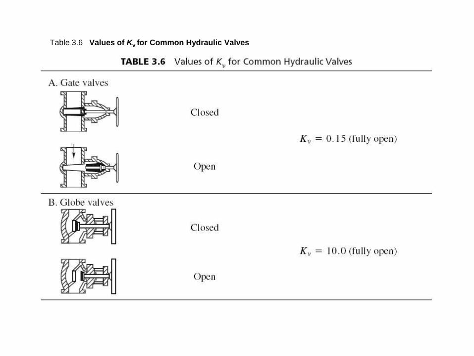
Table 3.6 Values of Kv for Common Hydraulic Valves

Table 3.6 (continued) Values of Kv for Common Hydraulic Valves
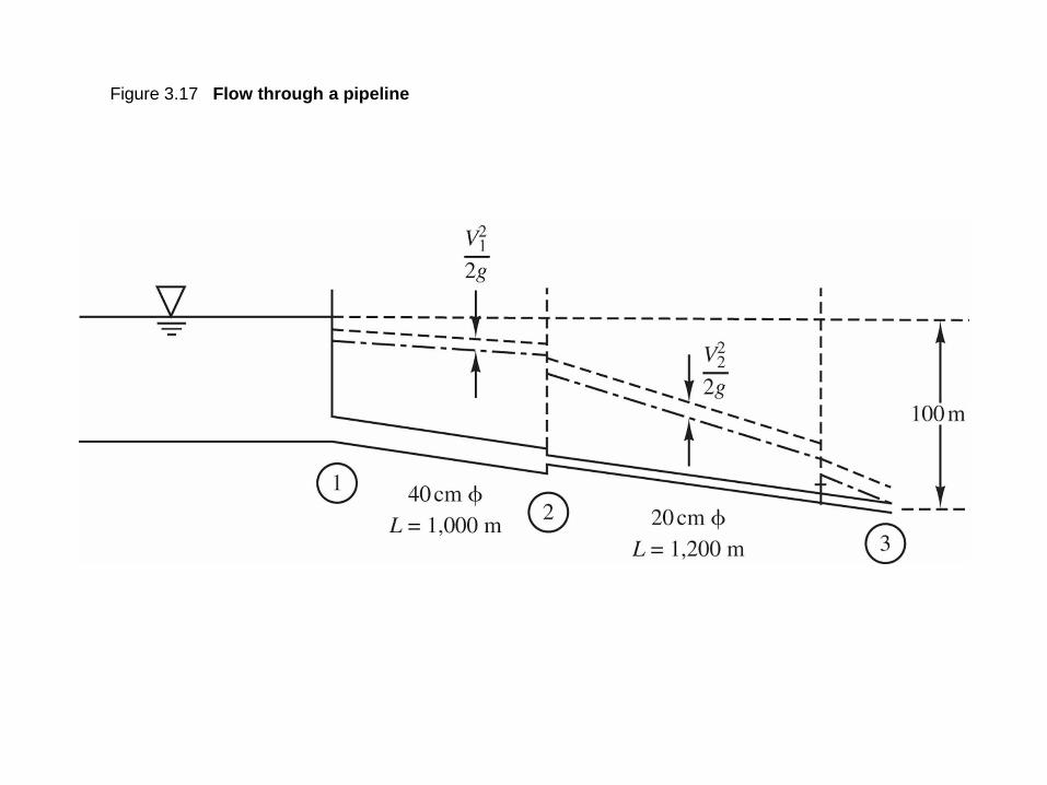
Figure 3.17 Flow through a pipeline

Figure 3.18 Pipes in series

Table 3.7 Equivalent Pipe Equations
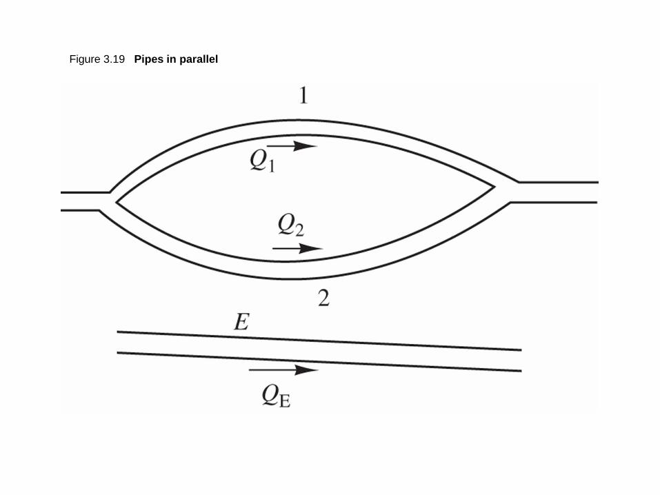
Figure 3.19 Pipes in parallel

Figure 3.20 Flow through parallel pipes

Figure P3.5.5
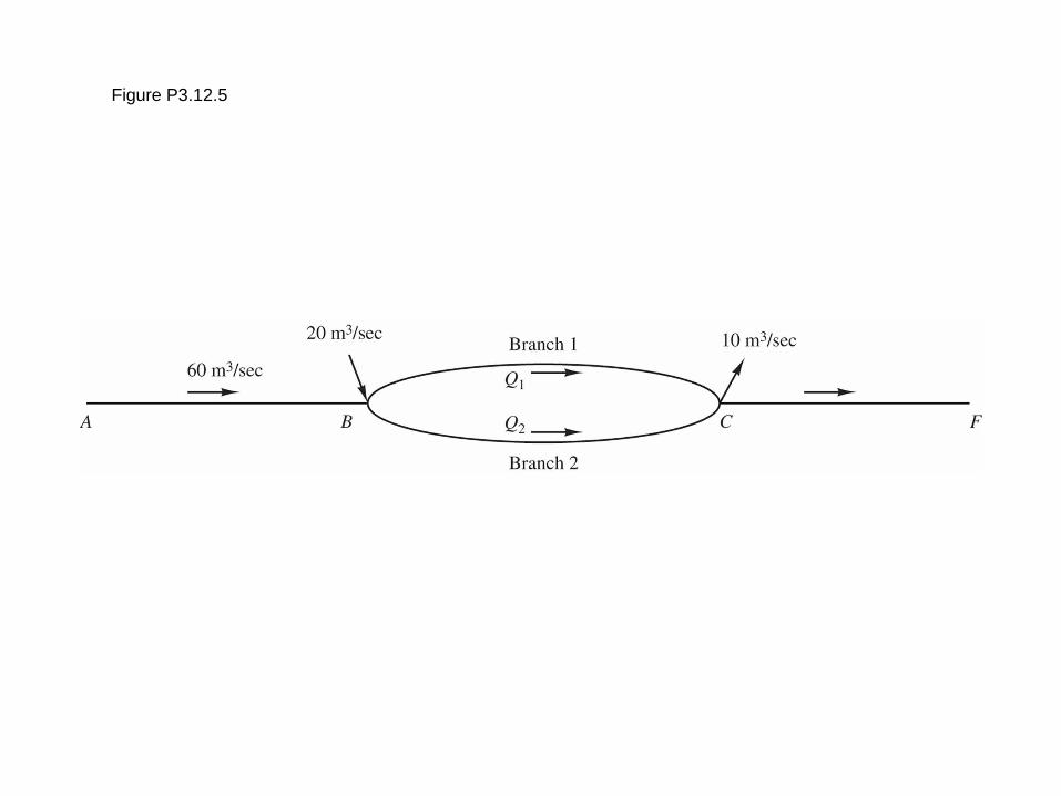
Figure P3.12.5