fifty year development: cons/ruction of steel arch … tower was mounted on each pier to support...
TRANSCRIPT

Fifty Year Development: Cons/ruction of Steel Arch Bridges 9

MIIDERII CIINSTRUCnll1l
PUblished by
American Institute of Steel Construction 1221 Avenue of the Americas New York. N,Y. 10020
O~"ICERS
Van W. Coddington, President D. B. Hughes,
First Vice President George W. Hall,
Second Vice President Robert P. Stupp, Treasurer John K. Edmonds,
Executive Vice President Leslie H. Gillette,
Assistant Executive Vice President William W. Lanigan,
Secretary and General Counsel
• DIT ORIAL STA ....
Daniel farb, Director of Publications Mary Anne Stockwell, Editor
R IiOIONAL 0 .... IC . 8
Atlanta, Georgia Birmingham, Alabama Boston, Massachusetts Chicago, Illinois Cleveland, Ohio Columbus, Ohio Dallas, Texas Denver, Colorado Detroit, Michigan Charlotte, North Carol ina Hartford, Connecticut Houston, Texas Los Angeles, California Memphis, Tennessee Milwaukee, Wisconsin Minneapolis, Minnesota New York, New York Oklahoma City, Oklahoma Omaha, Nebraska Philadelphia, Pennsylvania Pittsburgh, Pennsylvania St. Louis, Missouri San Francisco, california Seattle, Washington Syracuse, New York Washington, District of Columbia
VOLUME xv I NUMBER 2 I SECOND QUARTER 1975
CONTENTS
Fifty Year Development: Construction of Steel Arch Bridges
AISC Regional Engineering Staff
1975 ARCHITECTURAL AWARDS OF EXCELLENCE COMPETITION
..
3
16
The American Institute of SteeL Construction takes pleasure in announcing its sixteenth annual Architectural Awa"ds of Excellence Program to recognize and honor outstanding achitecCural design in steel and to encourage further exploration of the many aesthetic possibilities inherent in steeL construction.
All registered architects practicing professionally in the United States are invited to enter stee!-.framed buildings of their design constructed anywhere in the United States (defined as the 50 states, the District of CoLumbia, and aU U. S. Territories), and cO'Yltpleted after January 1, 1974 and prior to • August 29, 1975. Each building must have been designed, detailed, fabricated, and erected in the U. S., and aU structural steeL and plate ,nust have been produced in the U. S.
The structuraL frante of the building must be steeL, alth(}ugh it is not a requirement that the steeL be exposed and a part of the achitecturaL expression. Buildings of aU c/.assifications are eLigible, with equal emphasis given to all sizes and types in the judging. There is no limit to the number of entries by any individuaL or firm. Buildings named as previous AAE winners will not be eligible.
The members 0/ the 1975 Jury of Awards are:
Max Abramovitz, FA IA Harrison & Abramovitz, New YQ1'k, New York
Fred Ba"elli, FA IA Fred Bassetti & Company/ Architects, Seattle, WCUlhington
Charle. William Brubaker, FA IA Perkins & Will, Chicago, Illinms
Milo S. Kelchum, F.ASCE Profess()T of Civil Engineering, University of Connecticut, Storrs, Connecticut Consultant: Ketchum, Konkel, Barrett, Nickel & Austin Denver, CoLorado
Harlan E. McClure, FA IA Dean, CoUege of Architecture, Clemson University, Clemson, South Carolina
Competition rules are available from AISC, 1221 Avenue Of. the Ame!'icas, New York, N.Y. 10020. Entries must be postmarked prior to August 29, 1975.

- - Cl.. :» Q ::r rn e- rn - C/} ... OJ
OJ c-.> '< ...... (""')
...... ::r ,..., OJ :z (""') OJ ::r :::l G)
Cl.. rn :z Cl.. ~ ,..., rn rn ...... ,..., :::l CO :::u <: ~
rn :::l :z 0 G)
"0 '-rn C> C :::u • :z :» r-
• Please enter my subscription to the AISC ENGI NEERING JOURNAL
U. S. and Canada
1 Year $5.00 3 Years $12.50
Other Countries
Year $ 6.00 1 3 Years $1500
·Payable .n U. S. Fund$
Payment must be enclosed with thIS order. Make chec~s payable to AISC.
NAMl IpltJse pr1flt l
fiRM Olil Aff IllATION
ADORlSS
CITY SUll
Profession or occupation.
Engineer r.:: Architect o Educator '-' Othel
'< -l 0 0 CO ~ rn VI :::l CO -rn c::r ~ VI (""') ~ -0. ...... 0 :::> ...... 0 ...... ::r rn
,
liP COOL

• • - •
Q) • Q) en ....... Q) "'C en 10.. Q)
c: = Q) -= ....... Q b4 u c: .- = >0.. en 10.. = ,..... Q) ....... Q - "'C en ~
• dlZ AHINnOJ ' 31V1S
BUSINESS REPLY MAIL NO POSTACE STAMP NECESSARY If MAILED IN THE. UNITED STATES
- POSTAGE WILL BE PAID BY
AMERICAN INSTITUTE OF STEEL CONSTRUCTION 1221 Avenue of the Americas
New York. New York 10020
Attention; Paul R. Johnson
------------------------ -----
c..:» en -c:c Q) .c .......
~ :z -a:::: ~ L&.I c:c L&.I
:z :z - a:::: ~ :::::) :z Q L&.I -
SS3HOOV
fiRST ClASS
PERM IT No. 62<l38
NEW YORK. N, Y

•
•
FIFTY-YEAR DEVELOPMENT:
- :-'" --~-- -; .:-~~ ;. ~
Fig. l.-EadB Bridge, erection with. tieback cables (Courtesy 0/ J08eph E . Vollmar, Jr. )
Construction of Steel Arch Bridges
By Will iam F_ Hollingsworth, M_ ASeE Engineer, American Bridge Diy_, Un ited States Stee l Pittsburgh, Pa _
SECOND QUARTER 1975
The past 50 years have been a time of remarkable accomplishment in bridge buildi ng_ During this period there has been unprecedented growth and achievement in engineering, materials , fabrication, construction, and aesthetics_
It is the purpose of this article to review some of these developments as they pertain to steel arch bridges_ Primary emphasis will be on field construction. However, pertinent changes in the related areas of fabrication, materials, and design will also be reviewed. After these innovations have been examined briefly, they will be further explored by reviewing the actual construction of several representative arch bridges that have been built in the United States.
Reprinted with permission from the March 1975 Issue of the Journal of the Construction Divi· sian-Proceedings of the American SOCiety of Civil EnKineers (Vol. 101, Proceedings Paper 11187).
Historical Background One of the eminent engineers at the
start of this 50-year period, J. Waddell, often stated that bridge building did not become a science until the early part of the 20th century. However, in retrospect, perhaps there was a touch of science a little earlier. In 1868, construction was started on the boldest bridge of its day- The Eads Bridge at SI. Louis, Mo. This bridge, designed by James B. Eads, was the forerunner of arch bridges today. It was the first steel bridge, and actually it was the first important use of steel in any type of construction. The superstructure was the first that utilized hollow tubular members for structural strength. It was the biggest bridge ever built and the first to make extensive use of the cantilever method of erection.
The bridge was built without falsework by cantilevering out from the piers in counterbalanced stages. A temporary

wooden tower was mounted on each pier to support steel bars that acted as forestays and held up each half section of the arch as erection progressed. The dead weight of the bars was supported by additional wooden towers that were stationed at intervals along the arch (Fig. 1).
Erection went smoothly until the first two arch halves neared completion at midspan. The gap turned out to be too short and the closing piece could not be inserted. To obtain a larger opening, it was decided to pack ice in wooden troughs that were installed around the bottom portion of the tubular arch members. Unfortunately, the weather turned unseasonably hot and, even after using 60 tons of ice, the gap was still too short. The closure was finally made by substituting tubes with screw threads on the ends that provided adjustable lengths. This idea of a specially made keystone piece is still being used today.
The Eads Bridge stands as an important landmark in the history of bridges, for it ushered in the age of steel and with it a reliance on exact mathematical calculations, the analysis and technique of materials, and modern methods of bridge construction .
With the possible exception of the Honeymoon Bridge near Niagara Falls, the concept, procedure, and equipment used on the Eads Bridge remained unimproved upon in arch bridge construction for 40 years. However, with the construction of two major bridges in New York City-the Hell Gate Bridge in 1916 and the Bayonne Bridge 15 years later, there began a period of remarkable accomplishment. The accomplishments have culminated in recent years with the jacking of the Fre· mont Bridge in Oregon and the construction of the New River Gorge Bridge in West Virginia. The intervening steps have led to enormous changes and advances in bridge engineering, materials, application, and construction.
Major Developments
Computer-The greatest impact in the area of engineering has been the development of the electronic computer. The computer has liberated the engineer. No longer is he bound by mundane mathematical calculations that
4
would occupy nearly all of his productive time; now he can spend his time in a truly productive manner.
If an engineer is designing, his time can be spent on investigating many different types of bridges to give his client an aesthetic and pleasing structure at the least cost. In the area of construction, the computer allows the engineer to explore numerous types of erection schemes to obtain the one that is safest and the most economical. The computer also serves an ever increasingly important function in planning the sequence of construction. It tells the engineer and builder which parts of the construction path are most critical-in other words. where he should invest his time and energy.
Surveying-In recent years there have been numerous changes in the art and science of surveying. With the use of laser beams and small computers, accuracy that was previously unheard of can now be obtained. For example, distances across canyons can now be measured to an accuracy of less than '!ii-in. in several thousand feet. The present surveying instruments combine the capabilities of a theodolite, a distance measuring device, a small electronic computer, and a tape punch recorder-all in one instrument. At the touch of a button, everything is done automatically, i.e., atmospheric correction , signal strength changes, calibration, and slope changes. Substantial savings and greater accuracy have been the end result.
Aesthetics-The bridge engineer is also deeply concerned about aesthetics. Due to improved materials, connectors, and equipment the engineer has had greater success in fitting his bridge into the surrounding terrain. The steel bridges of today express the dominant spirit of the material-its simplicity, its strength, its power, and its beauty of form.
Material-The grades of steel have undergone a significant change. It has only been 100 years since the use of steel was initiated in bridge construction. In the early part of this century, the designer was limited to carbon, chromium, nickel, and silicon steel. A chromium steel was the first of the high·strength steels. It helped to re-
duce the amount of dead load and kept the size and thickness of sections down to a practical limit. Following chromium steel, the carbon-manganese steels arrived at approximately the same time as the heat-treated high-strength eyebars. These steels offered new design possibilities and have been extensively used for many years.
The constant quest for a more economical and stronger steel has led to the present family of steels. These range from carbon steel with a yield of 36 ksi (ASTM A36) to high-strength low-alloy steels with a yield of 50 ksi (ASTM A588 and A441), and to quenched and tempered alloy steel plate with a yield of 100 ksi (ASTM A514) .
Some of these steels (e.g., ASTM A242 and A588) are corrosion resistant and do not have to be painted. This type of steel forms a tightly adherent protective oxide film that substantially seals the surface against further corrosion. This protective oxide film gradually darkens and assumes a dark brown color. Not only does this color blend into the natural surroundings, but it also reduces maintenance and eliminates first-time paint costs.
Shop Fabrication-The two most revolutionary developments in shop fabrication are the use of numerically con· trolled (N / C) equipment and welding. While the full effects of N/C drilling are just beginning to be realized, welding has already had an enormous impact o~ field construction .
The N/C equipment can trace its beginning to the 18th century, when a French engi neer developed a loom controlled by an endless chain of perforated wooden ca rds. However, it was not until the early 1950's that the first true automatically controlled machine tool, a milling machine, was developed. This machine had the facility for remembering a set of instructions, which controlled the speed and feed rates of the milling cutters.
Recently, the industry has seen the quantity and application of N/C machines expand at an impressive rate, especially in the area of drilling. It has been demonstrated that the N/C drilling machine can produce a superior quality product at less cost than by traditional methods. Accuracy, repeti-
MODERN STEEL CONSTRUCTION
•
•
•

•
•
•
Fig. f.-Hell Gate Bridge, cantile116t' arm and tieback '1I8tem.
tiveness, and consistency are all more easily obtainable with numerical control. Shop assembly of field connections is no longer required. The N/C equipment has revolutionized certain areas of fabrication and its potential is still unlimited.
Fifty years ago arc welding was little more than a tool for repairing machinery. Progress was slow due to lack of suitable electrodes and welding power sources. Its use in manufacturing and fabricating was regarded with suspicion. However, as welding machines, electrodes, and knowledge of welding techniques improved, this suspicion gradually disappeared. Finally, during the 1950's, welding began to be used in the fabrication and erection of highway bridges. Since then, progress has been steady and arc welding is now universally used in steel bridge construction.
SECOND QUARTER 1975
Welding has many advantages. The more important ones include reduced weight, economy, rigidity, appearance, adaptability, efficiency, and the silence of the welding operation.
High-Strength 601t-The high-strength bolt also has had a tremendous impact in the area of connecting steels. The principal fastener in steel construction, until after World War II . was the hotdriven rivet. However, with the formation of the Research Council on Riveted and Bolted Structural Joints in 1947, the high-strength bolt soon became the prime fastener of structural steel. The ASTM A325 bolt provides joints of equal or greater strength than rivets at a considerable savings in both time and cost. This savings will be even more apparent with the use of the ASTM A490 bolt that has recently been approved for bridge construction under
the new American Association of State Highway Transportation Officials specifications.
Erection-Over the past 50 years, the methods of erecting have vastly improved the efficiency, time, and safety of bridge construction. The equipment and the contractor's method of erection have repeatedly been improved upon and perfected.
Three general methods concerning bridge erection have developed in regard to supporting the structure while it is being built: (1) falsework; (2) using some sort of tieback system during the cantilevering operation; and (3) various special schemes, e.g., the floatin, jacking, and lifting.
Until the late 1920's falsework was made of square timber formed into bents resting on wooden mud sills or piles. However, due to the advent of
5

heavier and longer bridges, plus yearround erection, there soon developed a demand and need for lighter reusable steel falsework. Presently, steel piles surrounded by steel cages are used underwater. The piles, in turn, support light steel bents. The Bayonne Bridge was one of the first structures to utilize steel falsework.
Often clearance requirements, strong tides, or the character of the river or canyon preclude the possibility of erecting falsework. In cases of this nature, the cantilever portion of the bridge is held in place by a tieback system. On the Eads Bridge, the tie system was a mixture of steel straps (called cables at the time) and timber falsework. This soon progressed to massive steel members with huge counterweights (as on the Hell Gate Bridge). As the years passed, lighter materials, e.g., wire bridge strand, were utilized. On the New River Gorge Bridge, presently being erected, the contractor is using a system of wire strand and oil drilling casinga material with exceptionally good tensile load-carrying capabilities.
Various special erection schemes have been used successfully. The recent jacking of the 6,000-ton Fremont arch span makes it one of the most remarkable events in the history of bridge building. A smaller arch, over Rondout Creek, near Kingston, N.Y., had its rib sections jacked up from a barge on specially designed towers.
The enormous changes and developments in arch construction can probably best be explored and understood by reviewing the actual construction of several representative arch bridges. While this paper will not cover all the structures worthy of analysis, it will present an overall view of the development of steel arch bridge construction.
Representat ive Structures
Hell Gate Bridge (Completed 1916) The Hell Gate Bridge was the prelude to this period of development in arch bridge construction. It was heralded as a "triumph of modern bridge engineering" and a "truly monumental bridge."
The bridge spans the East River in New York City and has a 977-ft span.
6
The roadway is suspended from the arch and carries four railroad tracks on a heavy ballasted sol id concrete deck. The arch is a two-hinged spandrel braced truss made from high-carbon steel.
The arch was erected by cantilevering each half from the abutment until the two halves met and were joined at midspan. To hold up each arch half, a massive steel tieback system including a 5,300-ton counterweight was used (Fig. 2). This system consisted of a tower located over the abutment that supported girders from the permanent structure. These girders acted as fore· stays and backstays by holding up half of the arch as erection progressed. Additional approach span girders, stacked at the rear of the backstays, formed the counterweight.
To control the erection of the two halves and their final connection, four large 2,500-ton hydraulic jacks were placed at the top of the temporary towers. At the time of closing, these jacks were able to move the ends of each cantilever a distance of 22V2 in.
The erection cranes (stiffleg derricks), which traveled along the top chords, were capable of lifting the heaviest pieces, which weighed up to 185 tons each. After the arch was completed, the deck was hung below it.
This bridge carried the steel arch to new dimensions of span length and weight and was, indeed, a monumental undertaking at the time. Hell Gate held the record span length for 16 years until the construction of the Bayonne Bridge.
Engineer: Gustav lindenthal Fabricator-Erector: American Bridge Div"
United States Steel
Tacony·Palmyra Bridge (Completed 1929) The opening of the Tacony-Palmyra Bridge in Philadelphia, Pa., was celebrated as a great occasion. However, the building of this 550-ft tied trussed arch should have been noted in the history books as an occurrence that was little understood or appreciated at that time.
The 18-in. I-beam hangers, which supported the tie and the deck roadway, cracked lafter only a few : month's of service due to wind vibrations. It was reported that the failures were due
to "fatigue" from overstresses caused . by the bending and twisting of the hangers during a storm. Remedial ac-tion consisted of adding a line of struts that cut down the slenderness ratio. This warning on aerodynamic oscilla-tion instability was not fully understood nor always heeded as a design or erec-tion criterion. In 1940, this type of instability resulted in the collapse of the Tacoma Narrows Bridge.
Engineer: Modjeski, Masters & Chase Fabricator-Erector: American Bridge Oi'o' "
United States Steel
Bayonne Bridge (Completed 1931) The Bayonne Bridge, across the Kill van Kull in New York City, is a structure of enduring greatness. It is a two-hinged steel arch with a length of 1,652 ft between end pins. The arch rib consists of two steel trusses 74ft center to center, 67 ft deep at the ends, and 37 ft deep at the center of the span. The roadway is of the half-through type with the central portion of the floor suspended from the arch ribs by wire rope hangers.
At the start of fabrication, the contractor offered to substitute a new type of steel. This offer was accepted and this new steel was used in place of the expensive nickel steel that had been specified for the bottom chord of the arch truss. This steel, a carbon-manganese type, was about 50% stronger than carbon steel and considerably cheaper than the nickel steel.
The wire ropes supporting the suspended deck were galvanized and designed for minimum elongation rather than strength. These ropes .were "prestretched," a new process, before cutting. Because of the prestretching and the accuracy of the enti re rope manufacturing process, only a small amount of shims were required to adjust for erection tolerances.
The bridge was built by cantilevering each half from its abutment with travelers mounted on the truss top chords. There were 10 steel falsework bents used to support the arch halves. These bents were placed and released successively as erection proceeded toward the center of the river. Transfer of load from one bent to another was done by jacks located in the falsework bents.
MODERN STEEL CONSTRUCTION
•
•

• The falsework bents rested on piers that consisted of four groups of square creosoted timber piles encased in steel boxes and all tied together by angle bracing.
Due to the location of the ship channel, the closure took place about 250 ft beyond the center of the arch. This erection scheme required the strengthening of several members by an increase in section or use of a higher grade of steel, or both.
Erection of the arch rib started with building a temporary tower behind each abutment upon which a stiftleg derrick was mounted. This derrick then erected the first few arch panels and an erection traveler. The traveler consisted of a 90-ton A-frame derrick mounted on legs that could be adjusted to keep the working platform level as the incl inat ion of the truss chord changed. The traveler ran on two lines of rails and was moved by a block and falls.
On the longer arch half, it was necessary to erect a temporary toggle truss to reduce the stresses. This toggle was made up of a post that was supported at a falsework bent location and inclined eyebar members connected to the top chord in both directions. Jacks were placed in the base of each toggle post to determine the relationship be· tween stress and required shim thickness.
At the point of closure, a 16-in. diam pin was used as a convenient method of centering the lower chord members as they came together. A supplementary mechanism to ensure horizontal alinement of the arch trusses was an interlocking device that had a tongue projecting from one arch half arm to engage a slot on the other arch half. Closure was obtained by lowering the two arch halves simultaneously by means of jacks located in falsework bents (Fig. 3).
• Fig. S.-BaJlonne Bridge, arch nearing cloaure
• SECOND QUARTER 1975
After closure, the remainder of the wire rope hangers were erected fol· lowed by the deck.
Presently. this bridge stands as an example of an engineering feat that in 1930 was considered l ittle short of miraculous. Its conception, its size, and its construct ion rema in outstanding. Its monumental span length is only now being surpassed-a record that has stood for 45 years.
Ensineer: O. H. Amm.nn Fabric.tor-Erector: Americ.n Bridge Dlv.,
United St.tes Steel
Henry Hudson Bridge (Completed 1936) The Bayonne Bridge was Soon followed by construction of the Henry Hudson Bridge over the mouth of the Harlem River in New York City. This bridge is a solid-rib deck arch with a span of 800 ft. Each rib was a box consist ing of two solid web riveted plate girders that were laced together to form a box. The arch
7
•
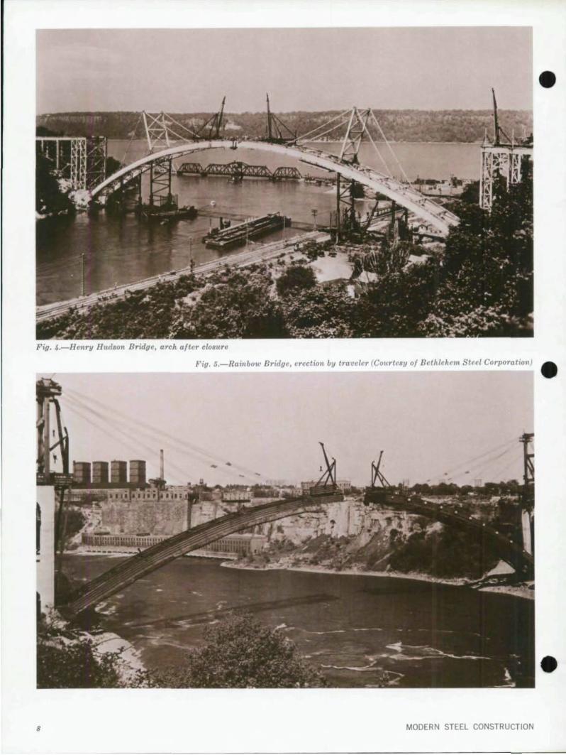
Fig. 4.-Henry Hudson Bridge, arch after closure
Fig. 5.-Rainbow Bridge, crection by traveler (Courtesy 0/ Bethlehcm Stccl Corporation) •
• 8 MODERN STEEL CONSTRUCTION

•
•
•
rib carries laced box columns that support the deck girders.
The two halves of the arch were cantilevered from the abutments on steel adjustable falsework bents (Fig. 4). Those bents over water were supported on steel piles located inside steel cages. The piles were driven through slots in the framework of the cages that served as submarine bracing. This piling was a large improvement over the wooden pi les used just five years earl ier on the Bayonne Bridge. Also, the falsework bent was made up from standard reusable sections.
Since the main channel of the river had to be left free of falsework, the contractor supported the ends of the cantilever arch halves by a toggle tieback system. A steel bent was built on top of the arch at a location direclly over the outermost falsework bent. This bent supported a light tiebar system of forestays and backstays that held both the cantilever arch sections and also a traveler that was used to lift and place the steel sections. After completion of the arch ribs, the deck girders were erected as the traveler backed off the arch.
Engineer: 0 , B. Steinm.n Fabricator·Erector: American Bridge Oiv.,
United Slates Steel
Rainbow Bridge (Completed 1941) One of the most spectacular deck arch bridges is the Rainbow Bridge at Niagara Falls. This bridge is a SOlid-rib deck arch and has a span of 950 ft. The arch rib is a riveted steel box 12 ft deep with an additional horizontal plate at mid-depth. Closed-box type columns, supported by the arch rib, carry the deck. The solid rib section was chosen instead of a trussed rib because of its architectural simplicity. However, this early concern for aesthetics led to a very slender or flexible arch in which secondary stresses had to be considered .
Due to the condition of the river bottom, a cable tieback system was chosen as the most economical way to support the cantilever arms. The tie· back system consisted of a steel bent made from permanent steel, which was placed on the forward end of the concrete approach viaduct. The backstay tie strands went from the top of the bent back 350 ft to concrete anchor
SECOND QUARTER 1975
blocks and the forestays went out from the bent top to connections on the arch. The forward ties were connected to the rib sections by bar and pin devices that allowed shortening and lengthening of the tie lengths in in· crements of one in .
Transferring the strands from one point of rib attachment to the next was a slow and tedious process. Each successive strand group was designed to create a minimum of interference so that one set of long strands could be pulled forward past a connected set. The strands were pulled forward by a continuous haul-line that ran from the hoisting engine up over the top of the cable bent down to the abutment, out to a snatch block at the rib connection , and then back to another drum on the hoist. A loose tie strand would first be attached to this haul·line near the abutment and then pulled by the haul· line out through the strands already connected to the new rib connection .
Pulling the tie strands to the actual connection and adjusting them to length was done by a special arrangement of falls that were pinned to the adjustable links, Cable stresses were measured by a special dynamometer clamped to the tie strand near the top of the cable bent. Handling these forestay strands was the most cosily single item in the erection sequence.
Due to the inherent requirements of a fixed arch for predetermined moments and forces, closure operations at the crown required a heavy jacking and alining device. This device consisted of two 500-ton jacks mounted along the top flange and two along the bottom flange and an alinement guide that connected to the bottom flange. After the installation of the keystone piece, the deck system and its columns were erected by the traveler derricks as they moved backward down the ribs (Fig. 5).
This bridge, the largest hingeless arch span at the time it was built, was one of the first to utilize a specially fabricated keystone piece. Construction involved an elaborate cable tieback system including stress measurement, which was a definite advancement over previous tieback systems.
Enlineer: Waddell and Hardesty Fabricator-Erector: Bethlehem Steel CorporatIon
Sl Georges Bridge (Completed 1941) A different arch type was introduced at the crossing of the Chesapeake and Del· aware Canal near St. Georges, Del, The consulting engineers designed a 540-ft span solid-rib tied arch with an extremely stiff tie and a shallow rib, The stan· dard design practice up unti l this time had been for the rib to be considerably heavier and stronger than the tie,
The erector took advantage of this stiffness in the erection scheme. The bridge was erected by utiliz ing falsework on one side of the river and cantilever erection involving a tieback on the other side. With the stronger tie, the erection required less falsework since the tie could cantilever over a longer distance without support and could also carry heavier erection equipment. Also, additional savings resulted from less overall weight and from the milling of compression splices in the lighter smaller rib.
Engineer: Parsons, Klapp, Brincke,hoff & DoUal.s Fabricator-Erector: Phoenix Bridae Comp.ny
Fort Pitt Bridge (Completed 1957) The Fort Pitt Bridge is a 750·ft, double deck truss-tied arch which spans the Monongahela River at Pittsburgh, Pa. The bridge carries four lanes of one· way traHic on each level and utilizes shallow box sections as arch ribs and a 25-ft deep truss as a tie. Most of the main members were fabricated with high-strength carbon-manganese steel (ASTM A440),
The final design was based on the analysis of a structure that was inde· terminate to the 15th degree, the unknowns being the 14 hanger stresses and the arch thrust. On earlier structures, the solving of this many simultaneous equations would have taken several man-weeks. With the use of the computer, which was still in its infancy, the mechanical solution was performed in two hours. (Today, that same mechanical solution would take less than one minute.1 The erector also util ized the computer to insure that the structure conformed to the correct geometrica I outlines as erection progressed, to obtain proper fit-up of the wire suspenders, rib, and tie at closing.
The bridge was built by supporting the truss tie on successive stages of falsework which were located out to the
9

Fig. 6.-Fort Pitt Bridge, erection by barge-mounted derrick
quarter-point of the arch. The stiffness of the tie, as in the 5t. Georges Bridge, was such that the truss tie could be cantilevered 175 ft beyond the last falsework bent to the center of the river. The erection of the rib followed immediately behind the truss, with the rib being supported by temporary columns mounted on the truss. The initial pieces were erected by a tower stiffleg derrick mounted on a barge (Fig. 6). As the pieces became lighter, erection was aided by travelers that were mounted on the top chord of the tie truss.
Closure was achieved by jacking longitudinally to close the truss tie top chord. The falsework bents located at the quarter-point of the arch were then lowered by jacks to close the rib.
Enaineer: Richardson, Gordon & Associates Fabricator-Erector: American Bridge Oi .....
United States Steel
10
Glen Canyon Bridge (Completed 1959) The Glen Canyon Bridge spanning the Colorado River is a deck arch located 700 ft above the canyon floor. Bu ilt for the Bureau of Rec lamation, the arch is a two-hinged truss type with a span of 1,028 ft.
At the start of construction, a 12'12-ton capacity cableway was erected 30 ft off the center line of the bridge. This cableway was used for the purpose of transporting men and equipment to either side of the canyon. Later, a 1,540-ft, 25-ton capacity cableway was built to erect the actual steel. The two masts for this cableway were mounted on two pins at right angles to each other so they could be tilted either forward or backward or to either side .
The arch halves were supported during erection by a tieback system. The tieback towers, located about 150 ft
behind the arch skewback, consisted of a steel braced bent that supported the tieback cables. The most unusual feature of the tieback system was the jacks that permitted the varying of tension in the lines. These jacks were located in strongbacks at points where the tieback cables were connected to the arch. As erection progressed, the jacks were also used to re l ieve tension in the rear tieback cables to transfer the load to the forward tieback cables.
Erection of the arch proceeded in a normal fashion with closure taking place approximately 90 days after the start of arch structural steel erection. The erection of the deck system and its supporting bents was completed about 70 days later.
Engineer: U. S. Bureau of Reclamation Fabricator: Judson Pacific Murphy Corporation Erector: Kiewit-Judson Pacific Murphy
MOOERN STEEL CONSTRUCTION
•
•
•

•
•
•
Sherman·Minten Bridl e (Completed 1961) The Sherman·Minton Bridge, across the Ohio River at Louisville, Ky., is of partic· ular interest. This six·lane double-deck bridge consists of twin (end to end) tied truss arches, each with a span of 800 It. Some of the developments incorporated during the design stage were the use of three different grades 01 steel, shop welding, high·strength bolts, and exten· sive use of the computer both lor de· sign and erection conditions.
The tie and some of the more highly stressed rib members were designed with what was then a new alloy heat· treated steel with a 100 ksi yield (ASTM A514). A 50 ksi yield steel (ASTM A242) was used for the floor beam frames and arch members where it would be most economical. The reo maining members were of 33 ksi yield carbon steel (ASTM A373).
Since all these materials were weld· able, it was economical to design the bridge for shop·welded fabrication. Gusset and splice plates were shop bolted to the main material and high· strength bolts were utilized in the field connections .
The consulting engineer made exten· sive use of the computer in several of the design phases. It was advantageous to be able to reanalyze the entire arch with a minimum of effort for each change in the design. The erector also made use of the computer in pre· paring the erection scheme.
The south arch was first erected by use of falsework bents. The north arch was built by cantilevering its north half Irom lalsework bents while the south hall cantilever arm was held by a tieback to the south arch that was already built. All steel was erected from the river by means of a Iloat ing derrick.
EnlinNr: Hazelet & Erd.1 Fabricator: R. C. McM.hon Company Erector: J. F. Beasley Construction Company
Lewisten·Queenston Bridge (Completed 1962) The Lewiston·Queenston Bridge across the Niagara River was also one of the lirst arch bridges to use high·strength bolts. The bridge consists of riveted box girder spans supported by a solid·ribbed deck arch. The arch spans 1,000 ft be· tween skewbacks in the gorge.
SECOND QUARTER 1975
Fig. 7.-Cold Spring Canl/on Bridge, cablewal/ a)ld cantilct'e r aTm
11
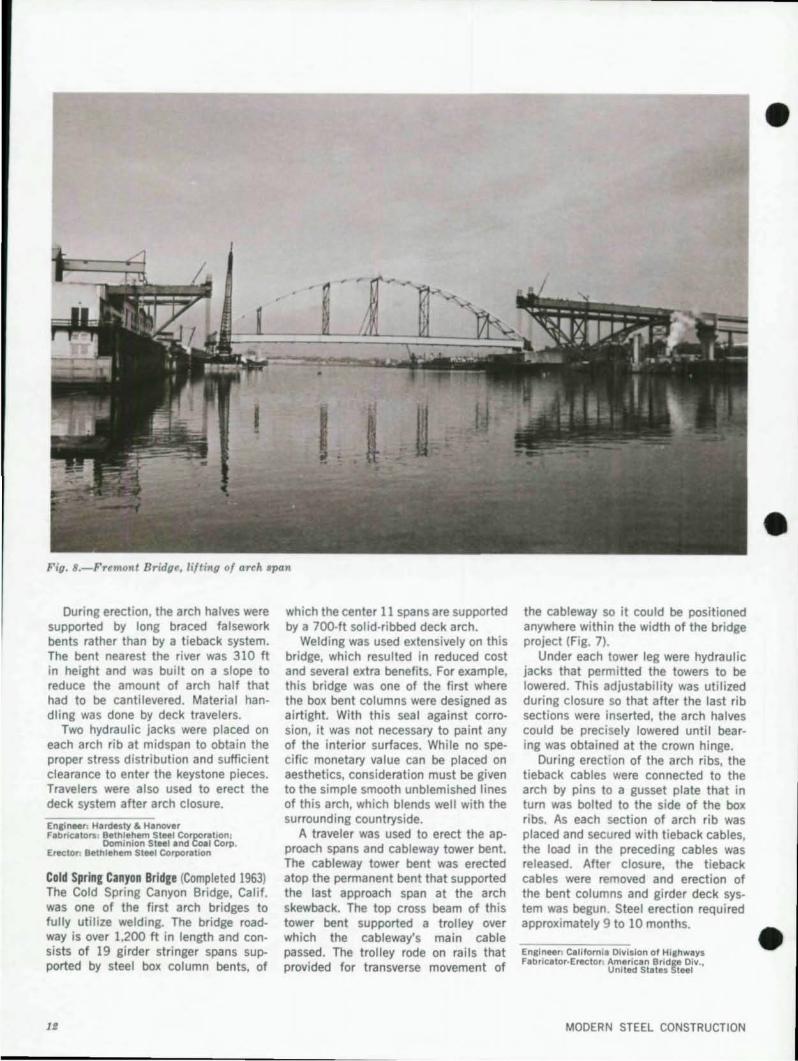
Fig. B.-Fremont Bridge, lilting 01 arch span
During erection, the arch halves were supported by long braced falsework bents rather than by a tieback system. The bent nearest the river was 310 ft in height and was built on a slope to reduce the amount of arch half that had to be cantilevered. Material handling was done by deck travelers.
Two hydraulic jacks were placed on each arch rib at midspan to obtain the proper stress distribution and sufficient clearance to enter the keystone pieces. Travelers were also used to erect the deck system after arch closure.
Enain",: H.rdesty & Hanove, fabricators: Bethlehem Steel Corporation;
Dominion Steel .nd Coal Corp. Erector: Bethlehem Steel Corporation
Cold Spring Canyon Bridge (Completed 1963) The Cold Spring Canyon Bridge, Calif. was one of the first arch bridges to fully utilize welding. The bridge roadway is over 1,200 It in length and consists of 19 gi rder stringer spans supported by steel box column bents, of
which the center 11 spans are supported by a 700-ft solid-ribbed deck arch.
Welding was used extensively on this bridge, which resulted in reduced cost and several extra benefits. For example, this bridge was one of the first where the box bent columns were designed as airtight. With this sea l against corrosion, it was not necessary to paint any of the interior surfaces. While no specific monetary value can be placed on aesthetics, consideration must be given to the simple smooth unblemished lines of this arch, which blends well with the surrounding countryside.
A traveler was used to erect the approach spans and cableway tower bent. The cableway tower bent was erected atop the permanent bent that supported the last approach span at the arch skewback. The top cross beam of this tower bent supported a trolley over which the cableway's main cable passed. The trolley rode on rails that provided for transverse movement of
the cableway so it could be positioned anywhere within the width of the bridge project (Fig. 7).
Under each tower leg were hydraulic jacks that permitted the towers to be lowered. This adjustability was utilized during closure so that after the last rib sections were inserted, the arch halves could be precisely lowered until bearing was obtained at the crown hinge.
During erection of the arch ribs, the tieback cables were connected to the arch by pins to a gusset plate that in turn was bolted to the side of the box ribs. As each section of arch rib was placed and secured with tieback cables, the load in the preceding cables was released. After closure, the tieback cables were removed and erection of the bent columns and girder deck system was begun. Steel erection required approximately 9 to 10 months.
Ensineer: Californl. Division of Hlahways Fabricator-Erector: American Bridge Div.,
United States Steel
MODERN STEEL CONSTRUCTION
•
•
•

•
•
•
Fremont Bridle (Completed 1973) One of the most notable tied arch erection procedures belongs to the Fremont Bridge across the Willamette River in Oregon. This bridge incorporates a stiffened solid·rib tied arch with an orthotropic upper deck and a conventional concrete lower deck. The arch spans 1.255 ft between spring points, which makes it the world's longest tied arch span.
The erection of the tied arch port ion of the bridge was done in a single l ifting operation (Fig. 8). This lift included the ribs, cable suspenders, tie gi rders, and the orthoptropic upper deck. Even with the lower deck not included, the lifted portion weighed 6,000 tons and was 902 ft long. This portion was assembled as one unit on falsework located upriver from the bridge site. After assembly was completed, a barge was floated in place and the span moved to the bridge site.
SECOND QUARTER 1975
The lifting units consisted of 32 threaded rods that were installed (eight to a corner) between the top of the anchor span and the bottom of the tied arch span. In each corner of the anchor span there were eight center-hole jacks. The rods extended through these jacks. The jacking was done in 24-in. strokes during which time a follower nut was conti nuously tightened against the support bracket. This insured independent mechanical support and the nut also sustained the load while the jack was being fleeted. The nuts were split down the middle and held in place by a slipin collar so they could be removed to permit rod coupling to pass through them. The span was jacked approximately 180 ft in about 40 hours of continuous operation.
Enlinur: Parsons, Brinckerhoff, Quade & Douala, Fabricators: Murphy Pacific Corporation
AmeriQn Bridge Oi ... .. United St.tes Steel
Erector: Murphy Pacifte Corporation
Paducah Bridge (Completed 1973) A jacking procedure similar to Fremont was also used on two 1,600-ton 535-ft tied arch spans on the Tennessee River near Paducah, Ky. One of the major differences between the two schemes was that on this bridge the jacking lift took place adjacent to the final position of the span. After the lift was completed, the span was skidded sideways to rest on concrete piers.
Enaineer: Kroboth Enliin .. ,s fabricator·Erector: Allied Structural Steel Co.
Glenfield Bridle (Scheduled 1975) The Glenfield Bridge across the Ohio River at Pittsburgh, Pa., incorporates several of the latest developments in tied arch bridge design and construction. The main river crossing is a 750-ft tied solid·ribbed arch, flanked by approach girder spans. The bridge will carry six lanes of traffic and will utilize three different grades of steel.
Fig. 9.-Glenfield Bridge, r ib erection
II

Fig. lO.-New River Gorge Bridge
As on several other recently tied arches, the tie for this bridge is considerably stiffer than the rib and carries a sUbstantial portion of the liveload moments. This extra depth of the tie allowed the erector to first erect and close the tie portion of the arch prior to working on the rib.
The arch tie was erected by using falsework bents to support the initial tie sections and then cantilevering the remainder of the tie section halves over the main channel of the river. The tie sections were erected by cranes mounted on barges. In order not to block the main channel for more than a few minutes during erection of the closing piece, a tie landing device was ut ilized to erect this final 150-ft section. This device consisted of beams attached to the top flange of the closing section. Each beam was cantilevered out beyond the end of the closing section so that it would come to rest on the previously erected portion of the tie. This device not only provided immediate support for the last tie section without having to wait for the splice to be completed, but also allowed the entire tie to be jacked longitudinally to eliminate the closing clearance.
The erection of the last rib section was accomplished by a similar device (Fig. 9). This rib landing device was mounted on each end of the closing rib piece and acted as a one-tooth gear. As this last piece was entered into its position and as the 10M was transferred from the rig to the adjacent ribs,
the tooth gear acted to close the gap. Consequently, when the full load of the last piece was on the structure, the rib was basically closed without jacking.
Ensineer: Richardson, Gordon & Associates Fabricators: PittSbU'fh-Des Moines Steel Company
Bristol 5 eel Company Erector: American Bridge Dill " United States Steel
Snake River Bridge (Scheduled 1976) A 993-ft trussed deck arch is presently being built to carry United States Highway 93 over Snake River near Twin Falls, Idaho. The arch has a rise of 210 It and supports the center portion of a 1,500-ft long girder roadway. Since both types of the high-strength steels used have a corrosion resistance of four times that of carbon structural steel, the bridge will not have to be painted.
The arch truss is being erected by cantilevering each half from its skewback. The cantilever arms are supported by an ingenious tieback system. The arch is light enough so that the forestay cables can be made up of three or four parts of 1 ¥loin. diam wire rope. These cables stretch from the arch tieback panel point back and up to the river end of the approach girders. The ropes are essentially endless in that one part stretches from a hoisting engine drum up to a set of sheaves on the girder, down to a sheave unit on the arch, and back to the sheave on the girders as many times as required to obtain the necessary strength. To move the tieback cables forward to a new position on the arch, the sheave
unit is unbolted and moved to the new point. As the unit is moved, the length 01 the ropes are automatically extended, thereby providing a very simple and inexpensive method of adjusting the lorestay cables.
Ensineer: Howard, Needles, Tammen & Bergendoff Fabricator-Erector: Allied Structural Steel Co.
Hew River Gorge Bridge (Scheduled 1976) The world's longest arch bridge, New River Gorge, is presently being built in West Virginia (Fig. 10). This bridge is 3,030 It in length and consists of two 34-ft roadways supported by 18-ft deep deck trusses. The deck trusses are divided into three continuous units. Two of the units serve as the approach structures and are supported by welded box column bents anchored into the mountainside. The box columns are tapered, with the tallest nearly 400 It in height. The remaining deck unit is supported by similar column bents mounted on a truss arch.
The truss arch has a span of 1,700 It and varies in depth from 53 ft near the skewbacks to 34 It at its center. The center of the arch is 800 ft above the bottom of the gorge. The truss chords are welded boxes up to 6 It in depth, with web plates up to 4 in. in thickness. All of the material in the bridge is unpainted corrosion-resistant steel (ASTM A588). During the design,
•
•
the engineer used the computer to • analyze stress patterns and determine the final geometric shape.
MODERN STEEL CONSTRUCTION

• All of the main field connections in
the deck truss spans and most of the main arch field connections were N/C drilled. This resulted in the elimination or reduction of the amount of shop assembly with a sizable cost savings for the owner.
The field material handling system consists of twin 3,500-ft cableways with two main cables suspended over the gorge from 330-ft towers. Each cableway has a 50-ton capacity. The cables are continuous over sheaves that are mounted at the top of the towers and run down to anchorages located 700 ft behind the towers. Each tower can be luHed 36 ft to each side by adjustable luffing guys. The first line for the cableway was flown across the gorge by a helicopter.
The approach spans were the first items erected. Due to the large capacity of the cableway, it was possible to assemble the deck trusses in the yard and then lift an entire truss span utilizing the cableways. A bent and an entire span of trusses, floorbeams, and
•
stringers could normally be erected in less than one week.
Once the approach spans were completed, the tieback system for the cantilever arch halves was built. The forward cable ties of this system are connected to jacking rods at the arch tieback points. The jacks are used both to attach and stress the wire ropes as well as to insure an equal stress distribution among the various parts. These forward ties extend back and up from the arch to connect to a rocking device that is mounted at the front end of the approach span. The horizontal component of these ties is carried back a distance of 600 ft to a concrete anchorage by four lines of high-strength oil drilling casing.
As succeeding sections of arch truss are erected and secured with new forward tieback cables, the preceding cables are released. At the time of closure, with the arch halves cantilevered B50 ft, each half will be supported by tieback cables from two different panel points.
The arch is being erected higher
• than its final position so that the arch halves can be precisely lowered until bearing is obtained. This lowering is
SECOND QUARTER 1975
done with jacks located in a jacking frame embedded in the casing tieback anchorage. After closure, all tieback cables will be removed and erection of the center deck truss unit with its bents will start from the center and move toward the approach spans.
En8ineer: Michael Baker. Jr., Inc. Fabricator-Erector: American Bridge Div"
United States Steel
Conclusions The two longest span arch bridges
were built at opposite ends of the 50-year period that is covered in this paper. These two bridges illustrate several of the significant changes in arch bridge construction that have developed over the past 50 years .
The design for the New River Gorge Bridge utilized the electronic computer. The design for the Bayonne Bridge was completely manual. The foundations for New River were located to within '!IIin. of theoretical, a far greater accuracy than was achieved on Bayonne. On New River, material of up to 4 in. in thickness was utilized, while the thickest plate on Bayonne was only 11,1., in. The New River Bridge is made from weathering steel and does not have to be painted. The various components of New River are shop welded, numerically controlled drilled, and field bolted. Those of Bayonne were riveted and reamed at assembly. Field handling of material is done by cableways on the New River Bridge. On Bayonne, travelers were required to move and lift the heavy steel pieces. The New River Bridge is being supported during construction by a tieback system of wire rope and oil drilling casing. Bayonne utilized falsework with wooden piles and eyebar toggle ties. Also, there is the change in aesthetics. The Bayonne Bridge is massive and monumental in size. The New River Gorge Bridge has a light and open overall appearance.
With both of these bridges, as well as those that came in between, there have been numerous accomplishments. However, what stands out in this past half century of achievement is man's continual thrust forward. The present steel arch bridges, as well as those of the future, fully express this irresistible urge of man.
Bibliography
"Arch Spans Jacked Up and Over Onto Piers," Engineering-News Record, Vol. 191 . No. 12, September 13, 1973, pp 18-19. Billings, H.t Sridges , Viking Press, New York, N.Y., 1956. Bruce, W. H" and Kring, C. V" "How St. Georges Tied Arch was Erected," Engineer· ing-News Record, Vol. 128, No. 1, January 1, 1942, pp. 26-28. "Cables Carry Niagara Arch to Closure," Engineering-News Record, Vol. 127, No. 9, August 28, 1941 , pp. 288-293. "Closing a 1652-FI. Steel Arch Bridge 2SOFt. Off Center," Engineering-News Record, Vol. lOS, October 23, 1930, pp. 640-64S. Feidler, L. L" "Erection of the LewlstonQueenston Bridge," Civil Englneer;ng, ASCE, Vol. 32, No. 11 , Nov., 1962, pp. SI).S3. Gahbauer, S, F , "World 's Largest Fixed Arch Bridge," Engineering and Contract Record, Vol. 7S, No. 7, July, 1962, pp. 60-62. Glen Canyon Bridge, BUreau of Reclamation, United States Department of the Interior, Denver, Colo., 1959
Hardesty, S., at aI., "Rainbow Arch Bridge over Niagara Gorge--A Symposium." T ransaelions, ASCE, Vol. 110, Papar No, 2236, 1945, pp. 1-178. Hazelet, C. p .. and Wood , R. H .. "Six-Lane Tied-Arch Bridge Across the Ohio," Civil Engineering , ASCE, Vol. 31, No. 11 , Nov .. 1961 , pp. 43-47. "Hlghline Erects Arizona Bridge," Western Conslruclion, Vol. 40, No.8, Aug., 1965, pp. 51-53. "High Wind Breaks Hangers In New TledArch Steel Bridge," Engineering-News Record, Vol. 103, October 17, 1929. Shulman, M. A., "California Scenic Bridge Features 700-FL Welded Steel ArCh," Modern Welded Structures, James F. Lincoln Arc Welding Foundallon, Cleveland, Ohio, 1965. Steinman, D. B., and Watson, S. R., Bridges and Their Builders, Dover Publications Co., New York, N.Y., 1957. Tokola, A. J., "Erecllng the Center Span 01 The Fremont Bridge," Civil Engineering. ASCE, Vol. 43, No.7, July, 1973, pp. 62-6S. Troelseh, H. W .. The Kill Van Kull Bridge, American Bridge Division, Plllsburgh, Pa., 1931 . Vollmar, J. E .. James B. Eeds and Ihe areal 51. Louis Bridge, Engineers' Club of St. Louis, St. Louis, Mo., 1974.
Waddell, J. A. L , Bridge Englne.rlng, Vot. 1, John Wiley and Sonl, Inc., New York, N.Y., 1916. "World's Biggest Heaviest Lilt Opens Bridge Building Chapter," Engineering-News Record, Vol. 190, No. 13, March 29, 1973, pp, 22-23.
15

AMERICAN INSTITUTE OF STEEL CONSTRUCTION 1221 Avenue of the Americas New York, N. Y. 10020
-----Address Correction Requested
r ~ Steel ~~ ~ "!.)
AISC REGIONAL ENGINEERING STAFF
Pacific Coast Area
lOS ANGELES, CALIF. 90015 Room tJOl-7f4 W. Olympic Boulevard James W. Mar.h, RegIonal Englneer-Supefv/slng Earl Roy aecker, Reglone' Engln •• ,
SAN FRANCISCO, CALIF. ~105 215 MalhI Str •• t, Room 827 Howard A. Schirmer, Regional Engl" •• ,
SEATTLE, WASH. 98104 405 Centre' Building. 810 3td "'"nue Elmer E Qunnelte, Se"'or R~lon.' Eng/n,.,
Midwestern Area
CHICAGO, Ill. 60603 Sufi. 1S123-25-176 We" Adams Str •• t Victor A. Walther, Jr., Reglon.' Eng/n .. t-Supervlslng Robert W. Shulde., Reglon.' Eng/,..ff
DENVER, COLO.-Englewood, Colo. 80110 Encull"l Sui'. 3237, 5 Denve, hchnologlcal Cenl., Oe"'.' A. Dunlap, Reglone' Eng /" .. ,
MILWAUKEE, WISC. $3222 10031 W. Lisbon A~.nu. Robert F. Lorenz, R.glon.1 Engln •• r
MINNEAPOLIS, MINN. 55420 Su/l. 133C, 8053 Bloomington F, •• w.y R.ymond H. R. TIde , R.glon.' Engln •• r
OMAHA, NEB. 68102 Room 82E-Clty N.tlon.' B.nk Building J.ck A. Donnelly, R.glon.' Engln .. r
ST. LOUIS, MO. 63105 Suit. 222-230 S. Beml.ton A~.nu. Clyd. A. Guder, Reglon.' Engln •• ,
Southwestern Area
DALLAS, TEXAS 75247 Suite 233-E, Mockingbird Tow.,. 1341 W. MockIngbird Lene Frederick S. Adams, Senior R.glonel Eng(neer
HOUSTON, TEXAS 77006 Sull. 1SO-L, Two Corpore'e Squlr. 3930 Kirby D,lve V. Del. L.n., Reg'on.' Engln."
OKLAHOMA CITY, OKLA. 73118 1016 N.W. 44th Street Floyd E. Hensley, Reglon.' Engln •• r
Eastern Central Area
CLEVELAND, OHIO 44113 Room 1232-$tend"d Building, 1370 Ont."o St. WIIII.m C. Keene, Reglon.1 Engln."
COLUMBUS, OHIO 43214 Sufte 203--4501 North High Stre.t H.yw.rd H. Dick, Reglonel Engln • .,
DETROIT, MICHIGAN 48226 "80 Penobscot BuildIng, 845 Gllswold Harold W. Gilley, Region.' Engln •• ,
PHILADELPHIA, PA. 19102 302 M.,lIn Tower Building, 1518 We/nul 51. Lawrence G. Adams , Reglonel Engln • .,
PITTSBURGH, PENNA. 15219 Q80·8 Union Trust Bulld/ng Chari,s M. Schubert, Regional Engine.,
Southeastern Area
ATLANTA, GA. 30305
BULK RAIE US POSTAGE
P A 10
NEW YORK. N Y. Permit No 6662
Room 223-3071 Peachtree Ro.d. HE. Roben W. Green, Reglon.' Engine"
BIRMINGHAM, ALA . 35216 3228E Lorn. Ro.d Roben J . Sch.lfh.usen, R"glon.' Englne.r
CHARLOTTE, N,C. 28203 P.O. BOK 3188, 1409 E.s' Bouf.~.rd Howlld F. Morris, Region.' Englne.r
MEMPHIS. TENN 38111
•
•
Room 445-Th. C.ntury Building, 3294 Popl'r Ayenu. Lewis B. Burgett, Region.' Engineer
WASHINGTON, DC.-Sprlnglield, V •. 22152 Suit. AJ04, 8138 Old Keen. 1.4111 Roed F Ayers Wliliamlon, Reglonel Engineer
Northeastern Area
BOSTON, MASS. 02116 25 Huntington A~.nu. Emil. W. J . Troup, Reglonel Engineer
HARTFORD, CONN. 06103 119 Ann Sl/eel Clprl.n A. Paurolo, Reglon.1 Engln .. ,
NEW YORK , N.Y. 10020 Suit. 1580, 1221 A~.nue 01 the Amerlc.s S.mlMl H. Marcus , Reglon.' Englneer~Su"'fVl.lng Remon P. Nlldon" Reglonel Engln.er Charles Pesh,k, Jr., Region.' Engine.,
SYRACUSE. N.Y 13210 143Q E," Boul.~ard, E. Chart .. L. Burnl , Reglon.' Engine., •
I