bridge inspection field manual - wisconsindot.gov · 145 masonry arch lf nbe 58 146 timber arch lf...
TRANSCRIPT

2014
BRIDGE INSPECTION FIELD MANUAL Wisconsin Department of Transportation


Table of Contents
1
Element List ............................................................................................................................................................... 3
The Wisconsin Department of Transportation’s Field Manual for Bridge Element Inspection ............................ 9 Chapter 1.
A. How to use this manual ................................................................................................................................ 9
B. Background ................................................................................................................................................ 10
Field ................................................................................................................................................................. 11 Chapter 2.
A. Inspection Planning and Preparation .......................................................................................................... 12
B. Performing the Inspection ........................................................................................................................... 13
C. Documenting the Inspection ....................................................................................................................... 13
D. General Guidance on Element Level Inspection ......................................................................................... 14
Condition State Descriptions ............................................................................................................................ 16 Chapter 3.
A. Steel ........................................................................................................................................................... 19
B. Reinforced Concrete ................................................................................................................................... 29
C. Prestressed Concrete ................................................................................................................................. 39
D. Timber ........................................................................................................................................................ 49
E. Masonry ...................................................................................................................................................... 58
F. Other Materials ........................................................................................................................................... 64
G. Bearings ..................................................................................................................................................... 68
H. Joints .......................................................................................................................................................... 74
I. Steel Protective Coatings ........................................................................................................................... 80
J. Concrete Wearing Surfaces ........................................................................................................................ 84

Table of Contents 2
K. Concrete Reinforcing Steel Protective Systems ......................................................................................... 88
L. Concrete Protective Coatings ..................................................................................................................... 90
M. Strengthening/Repair Systems ................................................................................................................... 92
N. Wall Elements ............................................................................................................................................. 96
Assessments .................................................................................................................................................. 100 Chapter 4.
National Bridge Elements ............................................................................................................................... 112 Chapter 5.
A. Decks/Slabs .............................................................................................................................................. 113
B. Superstructure .......................................................................................................................................... 116
C. Substructure ............................................................................................................................................. 127
D. Bearings ................................................................................................................................................... 137
E. Bridge Rail ................................................................................................................................................ 139
Bridge Management Elements/Agency Defined Elements ............................................................................. 141 Chapter 6.
A. Joints ........................................................................................................................................................ 142
B. Structural Approach Slabs ........................................................................................................................ 143
C. Protective/Strengthening Systems ............................................................................................................ 144
D. Wearing Surfaces ..................................................................................................................................... 146
E. Wall Elements ........................................................................................................................................... 147
Emergency Notification .................................................................................................................................. 149 Chapter 7.
NBI Rating System ......................................................................................................................................... 150 Chapter 8.
Field Abbreviations ......................................................................................................................................... 156 Chapter 9.

Element List
3
Element List
Decks/Slabs
Element Number Element Units Type Page Number 12 Reinforced Concrete Deck SF NBE 29
13 Prestressed Concrete Deck SF NBE 39
15 Prestressed Concrete Top Flange SF NBE 39
16 Reinforced Concrete Top Flange SF NBE 29
28 Steel Deck with Open Grid SF NBE 19
29 Steel Deck with Concrete Filled Grid SF NBE 19
30 Steel Deck with Corrugated/Orthotropic/Etc. SF NBE 19
31 Timber Deck SF NBE 49
38 Reinforced Concrete Slab SF NBE 29
8039 Prestressed Concrete Slab SF NBE 39
54 Timber Slab SF NBE 49
60 Other Material Deck SF NBE 64
65 Other Material Slab SF NBE 64
Superstructure
102 Steel Closed Web/Box Girder LF NBE 19
104 Prestressed Concrete Closed Web/Box Girder LF NBE 39
105 Reinforced Concrete Closed Web/Box Girder LF NBE 29
106 Other Material Closed Web/Box Girder LF NBE 64
107 Steel Open Girder/Beam LF NBE 19
109 Prestressed Concrete Open Girder/Beam LF NBE 39
110 Reinforced Concrete Open Girder/Beam LF NBE 29
111 Timber Open Girder/Beam LF NBE 49
112 Other Material Open Girder/Beam LF NBE 64
113 Steel Stringer LF NBE 19
115 Prestressed Concrete Stringer LF NBE 39
116 Reinforced Concrete Stringer LF NBE 29
117 Timber Stringer LF NBE 49

Element List 4
Superstructure
Element Number Element Units Type Page Number 118 Other Material Stringer LF NBE 64
120 Steel Truss LF NBE 19
135 Timber Truss LF NBE 49
136 Other Material Truss LF NBE 64
141 Steel Arch LF NBE 19
142 Other Material Arch LF NBE 64
143 Prestressed Concrete Arch LF NBE 39
144 Reinforced Concrete Arch LF NBE 29
145 Masonry Arch LF NBE 58
146 Timber Arch LF NBE 49
147 Steel Main Cables LF NBE 19
148 Steel Secondary Cables EA NBE 19
152 Steel Floor Beam LF NBE 19
154 Prestressed Concrete Floor Beam LF NBE 39
155 Reinforced Concrete Floor Beam LF NBE 29
156 Timber Floor Beam LF NBE 49
157 Other Material Floor Beam LF NBE 64
161 Steel Pin, Pin & Hanger Assembly or both EA NBE 19
162 Steel Gusset Plate EA NBE 19
8165 Steel Tension Rods/Post-Tensioned Cables EA ADE 19
8170 Other Primary Structural Members
Steel LF ADE 19
Reinforced Concrete LF ADE 29
Prestressed Concrete LF ADE 39
Timber LF ADE 49
Masonry LF ADE 58

Element List
5
Substructure
Element Number Element Units Type Page Number 202 Steel Column EA NBE 19
203 Other Material Column EA NBE 64
204 Prestressed Concrete Column EA NBE 39
205 Reinforced Concrete Column EA NBE 29
206 Timber Column EA NBE 49
207 Steel Tower LF NBE 19
208 Timber Trestle LF NBE 49
210 Reinforced Concrete Pier Wall LF NBE 29
211 Other Material Pier Wall LF NBE 64
212 Timber Pier Wall LF NBE 49
213 Masonry Pier Wall LF NBE 58
215 Reinforced Concrete Abutment LF NBE 29
216 Timber Abutment LF NBE 49
217 Masonry Abutment LF NBE 58
218 Other Material Abutments LF NBE 64
219 Steel Abutment LF NBE 19
220 Reinforced Concrete Pile Cap/Footing LF NBE 29
225 Steel Pile EA NBE 19
226 Prestressed Concrete Pile EA NBE 39
227 Reinforced Concrete Pile EA NBE 29
228 Timber Pile EA NBE 49
229 Other Material Pile EA NBE 64
231 Steel Pier Cap LF NBE 19
233 Prestressed Concrete Pier Cap LF NBE 39
234 Reinforced Concrete Pier Cap LF NBE 29
235 Timber Pier Cap LF NBE 49
236 Other Material Pier Cap LF NBE 64

Element List 6
Substructure
Element Number Element Units Type Page Number
8400 Integral Wingwall
Steel EA ADE 19
Reinforced Concrete EA ADE 29
Prestressed Concrete EA ADE 39
Timber EA ADE 49
Masonry EA ADE 58
Other Materials EA ADE 64
Culverts
240 Steel Culvert LF NBE 19
241 Reinforced Concrete Culvert LF NBE 29
242 Timber Culvert LF NBE 49
243 Other Material Culvert LF NBE 64
244 Masonry Culvert LF NBE 58
245 Prestressed Concrete Culvert LF NBE 39
Bearings
310 Elastomeric Bearing EA NBE 68
311 Movable Bearing EA NBE 68
313 Fixed Bearing EA NBE 68
314 Pot Bearing EA NBE 68
315 Disc Bearing EA NBE 68
316 Other Bearing EA NBE 68
Joints
300 Strip Seal Expansion Joint LF BME 74
301 Pourable Joint Seal LF BME 74
302 Compression Joint Seal LF BME 74
303 Modular Joint LF BME 74
304 Open Expansion Joint LF BME 74
305 Assembly Joint without Seal LF BME 74
306 Other Joint LF BME 74
Element List
7
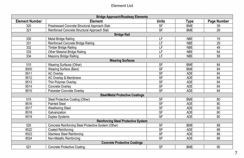
Bridge Approach/Roadway Elements
Element Number Element Units Type Page Number 320 Prestressed Concrete Structural Approach Slab SF BME 39
321 Reinforced Concrete Structural Approach Slab SF BME 29
Bridge Rail
330 Metal Bridge Railing LF NBE 19
331 Reinforced Concrete Bridge Railing LF NBE 29
332 Timber Bridge Railing LF NBE 49
333 Other Material Bridge Railing LF NBE 64
334 Masonry Bridge Railing LF NBE 58
Wearing Surfaces
510 Wearing Surfaces (Other) SF BME 84
8000 Wearing Surface (Bare) SF BME 84
8511 AC Overlay SF ADE 84
8512 AC Overlay & Membrane SF ADE 84
8513 Thin Polymer Overlay SF ADE 84
8514 Concrete Overlay SF ADE 84
8515 Polyester Concrete Overlay SF ADE 84
Steel/Metal Protective Coatings
515 Steel Protective Coating (Other) SF BME 80
8516 Painted Steel SF ADE 80
8517 Weathering Steel SF ADE 80
8518 Galvanization SF ADE 80
8519 Duplex Systems SF ADE 80
Reinforcing Steel Protective System
520 Concrete Reinforcing Steel Protective System (Other) SF BME 88
8522 Coated Reinforcing SF ADE 88
8523 Stainless Steel Reinforcing SF ADE 88
8524 Non-Metallic Reinforcing SF ADE 88
Concrete Protective Coatings
521 Concrete Protective Coating SF BME 90
Element List 8
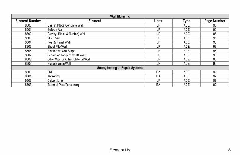
Wall Elements
Element Number Element Units Type Page Number 8600 Cast in Place Concrete Wall LF ADE 96
8601 Gabion Wall LF ADE 96
8602 Gravity (Block & Rubble) Wall LF ADE 96
8603 MSE Wall LF ADE 96
8604 Post & Panel Wall LF ADE 96
8605 Sheet Pile Wall LF ADE 96
8606 Reinforced Soil Slope LF ADE 96
8607 Secant or Tangent Shaft Walls LF ADE 96
8608 Other Wall or Other Material Wall LF ADE 96
8609 Noise Barrier/Wall LF ADE 96
Strengthening or Repair Systems
8800 FRP EA ADE 92
8801 Jacketing EA ADE 92
8802 Culvert Liner LF ADE 92
8803 External Post Tensioning EA ADE 92

Chapter 1 – The Wisconsin Department of Transportation’s Field Manual for Bridge Element Inspection
9
The Wisconsin Department of Transportation’s Field Manual for Bridge Element Inspection Chapter 1.
This Manual is designed to aid Bridge Inspectors in performing accurate and consistent bridge inspections and was developed for convenient
use in the field. Please read this Manual carefully. The user should consult the Structure Inspection Manual for more complete details on the
inspection program. Refer to the procedures in the Foreword of the Structure Inspection Manual to notify the author of any future comments or
revisions for this Manual.
This Manual contains information on Field and Element Level Inspections; Condition state descriptions; National Bridge Elements (NBE), Bridge
Management Elements (BME), and Agency Defined Elements (ADE); Assessments; and other useful information. Inspectors should use this
manual in conjunction with the Bridge Inspection Report form, and record all deficiencies as well as any comments about the bridge inspection
procedure, problems encountered, etc. on the Bridge Inspection Report form and appropriate supplemental forms (as needed).
A. How to use this manual
Bridge inspection documentation using this manual consists of defining the bridge elements (parts of the bridge), identifying the material type of
each element, determining their total quantities, evaluating their condition based on the material defects, and properly documenting the findings.
The condition of each element is determined by performing a field inspection, assigning condition states that correlate to the severity of the
defects, and recording the quantities of the defects in each element. Condition States for each element are defined within this manual. The
condition assessment is complete when the appropriate portion of the total quantity is allocated over the defined condition states.
Due to the nature of the Element Level inspection, inspectors will be coding the condition states of various material defects for elements. The
Department will only code the worst case scenario defects for each element per unit of measure. This will be representative of the overall
element condition state for that unit of measure. Once all of the material defects are ascertained, the inspector will then allocate the appropriate
condition states for the overall element based on the condition states of the various material defects. Since only worst case scenario defects will
be recorded in the condition state table, it will be essential that the inspector take thorough notes to ascertain the location of all defects located
throughout the element.

Chapter 1.B – Background 10
This Manual attempts to cover the vast majority of all bridge elements found on bridges in Wisconsin. An inspector may find materials or
elements that are not defined during the course of their inspection. In these cases, the inspector should use judgment to select the closest
element match. In a similar manner, there may be cases when the specific condition observed in the field is not defined in this manual. In these
cases, the inspector should use the general description of the condition states for material defects to determine the appropriate condition states.
B. Background
The Wisconsin Department of Transportation’s Bridge Inspection Field Manual builds on the element level condition assessment methods
developed in the AASHTO Manual for Bridge Element Inspection, 1st Edition, 2013. Improvements have been made to fully capture the condition
of the elements by reconfiguring the element language within the defined condition states. The overall condition of an element can be utilized in
this aggregate form, or broken down into specific defects present as desired by the agency for Bridge Management System use.
The Wisconsin Department of Transportation’s Bridge Inspection Field Manual provides a comprehensive set of bridge elements and
assessments that is designed to be flexible in nature to satisfy the needs of all agencies. The complete set of elements capture the information
necessary for an agency to manage all aspects of the bridge inventory utilizing the full capability of a BMS.
The element set from the AASHTO Manual for Bridge Element Inspection, 1st Edition, 2013, is presented within and includes three element
types; National Bridge Elements (NBE), Bridge Management Elements (BME), and Agency Developed Elements (ADE). All elements, whether
they are NBE, BME, or ADE utilize four (4) condition states.
Condition State 1 = Good Condition State 2 = Fair Condition State 3 = Poor Condition State 4 = Severe
The level of detail of the defects is typically eliminated for Condition State 4, as this condition state is reserved for severe conditions that are
beyond those specific defects defined in Condition States 1 through 3 and may often have load capacity implications. However, some specific
guidelines are provided for Condition State 4 in this Manual to promote consistency.

Chapter 2 – Field
11
Field Chapter 2.
The following chapter is to be used as a field guide for the inspector at the bridge site. Any information in this chapter can be expanded upon in the WisDOT Structure Inspection Manual and the AASHTO Manual for Bridge Element Inspection.

Chapter 2.A – Inspection Planning and Preparation 12
A. Inspection Planning and Preparation
1) Identify bridge elements
i. Review as-built drawings and identify each element. If forms exist, review and verify the element data (design, material, and quantity) matches the as-builts.
ii. Calculate quantities for each element and compute or verify the total quantity for the bridge.
2) Prepare field forms and sketches
i. Prepare forms in HSI and sketches for documenting condition states in the field. Forms should accommodate all defect types as applicable and provide sufficient room for adding inspection notes.
ii. Verify the bridge elements (number and name) on the HSI form and the associated total quantities. Leave room for additional elements that may be discovered in the field. For existing forms and sketches, review content and update as needed.
3) Develop inspection plan
i. The inspection plan should include procedures for collecting element data. Consider inspection sequence and access when developing the plan. Elements are generally evaluated in 3 dimensions and will have overlapping defects. The defects will be assessed on type and severity. All defects must be considered in the determination of controlling condition states.
ii. Review and update procedures outlined in the bridge inspection report as necessary to identify changes to the bridge or new requirements.
iii. Record bridge specific inspection plans and procedures on the inspection form

Chapter 2.B – Performing the Inspection
13
B. Performing the Inspection
1) Record defects
i. Record type, severity, and extent of defects on the sketches and forms provided using the standard terminology and descriptors.
ii. Track defects throughout the element and identify overlapping defects. iii. Identify worst case scenario defects for a given element (within a unit of measure) and record this on your inspection form. iv. Begin new notes with month/year of current inspection. Take thorough notes to identify location of worst case scenario
defects, and well as global defects. It will be necessary for the inspector to document exact location, orientation, length, and size of each defect. This will be essential for repeatability during future inspections. Document CS 3 and CS 4 defects with photos.
v. If corrosion or debris build-up prevents visual inspection, then the inspector must clean accordingly to properly ascertain the condition of the element.
2) Identify condition states and quantities
i. Identify the condition states and the associated quantities for each defect. ii. Based on defect condition states, apply the applicable condition states to the element.
3) Conduct Quality Control (QC)
i. The Team Leader is responsible for QC to include verifying proper condition states and quantities have been applied.
C. Documenting the Inspection
1) Complete Agency forms
i. Use standard forms (Highway Structures Information System - HSI) to enter element data and inspection notes.
2) Update forms
i. Based on field work, update forms and sketches as needed to include changes in condition states from previous
inspections and correcting errors (wrong element numbers, missing elements, wrong quantities, etc.).

Chapter 2.D – General Guidance to Element Level Inspection 14
3) Make recommendations
i. The inspector should place applicable maintenance recommendations within the inspection report to correct deficient
elements and to arrest further deterioration of the element.
D. General Guidance on Element Level Inspection
1) Structural defects shall be used in conjunction with material defects. That is defect overlap is not considered when reporting
structural defects (recording quantities in the appropriate defect Condition States) but should be accounted for when rolling up the
quantities.
2) Where multiple condition states exist within a unit of measure, the most predominant defect in severity AND extent controls; i.e.,
the condition state that gets reported within that unit of measure. The quantity of the more severe condition state, accounting for
overlapping defects, is computed and reported first followed by successively less severe condition states. The sum of all of the
reported condition states must equal the total quantity of the element.
i. Example: a deck has 25sf on the bottom surface in Condition State 2 for cracking in the SE corner of a bridge and 15sf on
the bottom surface of Condition State 3 for spalling in the SE corner of the bridge. 15sf would be recorded in Condition
State 3 for spalling and 10 SF would be recorded in Condition State 2 under the cracking defect since they overlap each
other. The 15sf of Condition State 3 found on the bottom surface would control over the overlapping Condition State 2.
3) Elements are evaluated as one unit of measurement; linear feet (LF), square feet (SF), and each (EA) at a time. All defects
contained within that unit are recorded for that unit. Each unit of measure for each element is evaluated for all defects associated
with that element with the worst case noted and recorded.
4) When calculating LF, the quantity should include the sum of all the lengths of each section.
i. Example: Bridge girders are 100 feet long and there are five girders; Total quantity will be 500 LF.

Chapter 2.D – General Guidance to Element Level Inspection
15
5) Quantifying defects in elements using LF will be the size of the defect rounding up to the nearest whole foot. For units of LF and
EA, the height/depth of the defect does not factor into the quantity calculation, but may affect the condition state. For units of SF,
any defect within 1 SF will be recorded as 1 SF regardless of the extent of that defect.
i. Example: A defect 0.9 foot long by 0.1 foot high or a defect 0.9 foot long by full height of girder will both be recorded as 1
LF of defect.
ii. Example: A 2.8 foot long defect will be recorded as 3 LF, while a 3.2 foot long defect will be recorded as 4 LF.
6) The condition states of the element are based on the descriptions provided. In general, the four condition states are defined as
follows:
Condition State 1 (Good) – Any deficiency is minor and has no impact on the performance of the element. Any deficiencies
that exist would be expected for the material and bridge construction used.
Condition State 2 (Fair) – The deficiency has advanced but with no impact on the performance of the element. Deficiencies
are the result of exposure to the elements with insufficient maintenance to maintain the element in good condition. Under
continued exposure, the element will degrade further.
Condition State 3 (Poor) – The deficiency has advanced further and additional deterioration will ultimately impact the
strength and/or serviceability of the element
Condition State 4 (Severe) – The deficiency has advanced to the point where the strength or serviceability of the element
may be affected and a structural review is necessary to determine the effect on strength or serviceability of the element or
the bridge. The Team Leader shall elevate this deficiency to the attention of the Bridge Safety Inspection Manager to
determine if any action is required. Structural reviews may include a review of the field inspection notes and photographs,
review of as-built plans, or an analysis as necessary. If an evaluation determines strength or serviceability is not affected,
then the Condition State can be changed to 3.
Chapter 3 – Condition State Descriptions 16
Condition State Descriptions Chapter 3.
The condition states listed below are organized by material types that will typically be found on a bridge. The list provided is not intended to be
all encompassing but instead is assumed to supplement the inspector’s knowledge and experience. The specific bridge elements will refer back
to these condition states to comprehensively evaluate each member of a bridge.

Chapter 3 – Condition State Descriptions
17
THIS PAGE IS INTENTIONALLY LEFT BLANK

Chapter 3.A – Steel 18
Chapter 3.A Steel

Chapter 3.A – Steel
19
A. Steel
Steel Decks
28 – Steel Deck with Open Grid SF
29 – Steel Deck with Concrete Filled Grid SF
30 – Steel Deck with Corrugated/Orthotropic/Etc. SF
Superstructure
102 – Steel Closed Web/Box Girder LF
107 – Steel Open Girder/Beam LF
113 – Steel Stringer LF
120 – Steel Truss LF
141 – Steel Arch LF
147 – Steel Main Cables LF
148 – Secondary Steel Cables LF
152 – Steel Floor Beam LF
161 – Steel Pin, Pin & Hanger Assembly or both EA
162 – Steel Gusset Plate EA
Substructure
202 – Steel Column EA
207 – Steel Tower LF
219 – Steel Abutment LF
225 – Steel Pile EA
231 – Steel Pier Cap LF
8400 – Integral Wingwall EA
Culvert
240 – Steel Culvert LF
* Where an element is not clearly visible to the inspector, an
In-Depth inspection may need to be scheduled so that
proper equipment, cleaning, access, traffic control, etcK can
be mobilized to adequately inspect, assess, and properly
document any defect’s condition state.
Other
330 – Metal Bridge Railing LF
8165 – Steel Tension Rods/Post-Tensioned Cables EA
8170 – Other Primary Structural Members LF

Chapter 3.A - Steel 20
Narrative:
• The protective coating does not affect the condition state (CS) of the steel elements. Protective coating deterioration will be rated under
Element 515, 8516, 8517, 8518, or 8519.
• Section loss is not defined by a localized area but as the section loss of an entire member by cross-sectional area.
• Any steel cracks not previously detected should be evaluated to determine the potential for fracture. The amount of redundancy and the
number of affected primary members will influence the placement of this defect in CS 3 or 4; i.e., the greater the redundancy and/or
fewer members that have cracking will most likely be in CS 3.
• Distortion or out of plane bending in compression regions requires greater scrutiny compared to the same level of damage in a tension
region.
• For through trusses or through arches, the upper bracing (lateral and vertical) will be evaluated and coded under Element 120 – Steel
Truss or Element 141 Steel Arch, respectively. The bracing will be split down the center with each half evaluated with the respective
primary truss or arch. The lower lateral bracing will be evaluated under Assessment 9169.
• Element 207 is to be used for truss framed tower supports or built up steel towers and is calculated by the sum of the heights of each
tower. This element is intended to capture large supports and towers associated with suspension bridges, cable stayed bridges,
movable bridges, or similar structural configurations.
• Element 162 – Steel Gusset Plate: Used for gusset plates in the plane of the truss or arch, or connecting portal members to the truss or
arch. Gusset plates connecting bracing members, stringers, floor beam, etc. will be evaluated with their respective members. Gusset plates will be measured as one per panel point, regardless of the number of plates used to comprise the connection. Distress observed on built up gusset plates should be considered. Nondestructive testing results should be taken into consideration if available.
• Element 8170 – Other Primary Structural Members: Examples of elements that should be coded under this element include Purlins,
Diaphragms on curved girder bridges, etc.
• Through arch cables will be rated as Element 148, Secondary Cables.
• Element 147 – Steel Main Cables is intended for use on the exposed sections (not embedded in concrete) of main cables (typically two)
in suspension bridges, or each cable stay in cable-stayed bridges.
• Element 148 – Secondary Steel Cables will be defined as the exposed sections of suspender cables on suspension bridges, or
dampening cables on cable-stayed bridges.

Chapter 3.A – Steel
21
• Element 161 - Steel Pin, Pin & Hanger Assembly or both - Distress observed on either plate should be considered. Ultrasonic testing
results should be taken into consideration if available.
• If condition warrants analysis, indicate in the notes why it should be done.

Chapter 3.A – Steel 22
Defect CS 1 CS 2 CS 3 CS 4
Good Fair Poor Severe
Corrosion (1000)
None Freckled rust. Corrosion of the
steel has initiated.
Section loss is evident or pack rust is present but does not warrant
structural review. The condition warrants a structural review to determine the effect on strength or serviceability of the
element or bridge; OR a structural review has been completed and the defects impact strength or serviceability of the element or
bridge.
Cracking (1010)
None Crack that has self arrested or has been arrested with effective arrest holes, doubling plates, or similar.
Identified crack exists that is not arrested but does not warrant
structural review.
Connection (1020)
Connection is in place and
functioning as intended.
Loose fasteners or pack rust without distortion is present but the
connection is in place and functioning as intended.
Missing bolts, rivets, broken welds, fasteners or pack rust with distortion
but does not warrant a structural review.
Distortion (1900)
None Distortion not requiring mitigation
or mitigated distortion.
Distortion that requires mitigation that has not been addressed but does not
warrant structural review. Substructure Only
Settlement (4000)
None Exists and has been arrested with
effective countermeasures.
Minor settlement has occurred. Countermeasures have been taken
but movement is still evident. Currently does not warrant
a structural review.
The condition warrants a structural review to determine the effect on strength or serviceability of the
element or bridge; OR a structural review has been completed and the defects impact strength or serviceability of the element or
bridge.
Scour (6000)
None
Scour has exposed the top of the footing. No undermining is evident. Counter measures are in place and
functioning. Minor scour around pile bents. No significant loss of channel material compared to
previous measurements.
Scour has exposed vertical face(s) of the footing. No undermining of
spread footing or minor undermining of pile supported footing. Moderate
scour around pile bents. Measurements indicate active
channel movement. Structural review not warranted.
Chapter 3.A – Steel
23
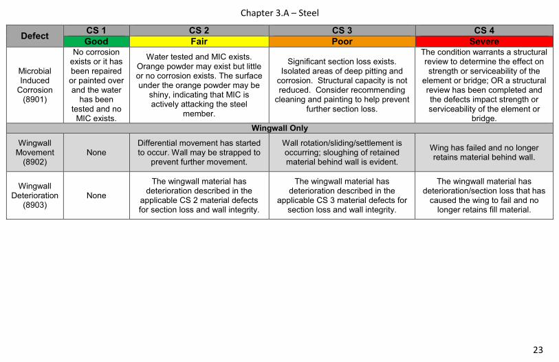
Defect CS 1 CS 2 CS 3 CS 4
Good Fair Poor Severe
Microbial Induced
Corrosion (8901)
No corrosion exists or it has been repaired or painted over and the water
has been tested and no
MIC exists.
Water tested and MIC exists. Orange powder may exist but little or no corrosion exists. The surface under the orange powder may be
shiny, indicating that MIC is actively attacking the steel
member.
Significant section loss exists. Isolated areas of deep pitting and
corrosion. Structural capacity is not reduced. Consider recommending
cleaning and painting to help prevent further section loss.
The condition warrants a structural review to determine the effect on strength or serviceability of the
element or bridge; OR a structural review has been completed and the defects impact strength or serviceability of the element or
bridge. Wingwall Only
Wingwall Movement
(8902) None
Differential movement has started to occur. Wall may be strapped to
prevent further movement.
Wall rotation/sliding/settlement is occurring; sloughing of retained material behind wall is evident.
Wing has failed and no longer retains material behind wall.
Wingwall Deterioration
(8903) None
The wingwall material has deterioration described in the
applicable CS 2 material defects for section loss and wall integrity.
The wingwall material has deterioration described in the
applicable CS 3 material defects for section loss and wall integrity.
The wingwall material has deterioration/section loss that has
caused the wing to fail and no longer retains fill material.

Chapter 3.A - Steel 24
Condition State 2 Condition State 3 Condition State 4
Corrosion
Cracking

Chapter 3.A – Steel
25
Condition State 2 Condition State 3 Condition State 4
Connection
Distortion

Chapter 3.A - Steel 26
Condition State 2 Condition State 3 Condition State 4
Settlement
Scour

Chapter 3.A - Steel
27
THIS PAGE IS INTENTIONALLY LEFT BLANK

Chapter 3.B – Reinforced Concrete 28
Chapter 3.B Reinforced Concrete

Chapter 3.B – Reinforced Concrete
29
B. Reinforced Concrete
Deck
12 – Reinforced Concrete Deck SF
16 – Reinforced Concrete Top Flange SF
38 – Reinforced Concrete Slab SF Superstructure
105 – Reinforced Concrete Closed Web/Box Girder LF
110 – Reinforced Concrete Open Girder/Beam LF
116 – Reinforced Concrete Stringer LF
144 – Reinforced Concrete Arch LF
155 – Reinforced Concrete Floor Beam LF
**The inspector should use judgment when utilizing condition state defect definitions; considering concrete crack type, location, and orientation.
Where required, an In-Depth inspection may need to be scheduled so that proper equipment, cleaning, access, traffic control, etcK can be
mobilized to assess and properly document any defect’s condition state.
Substructure
205 – Reinforced Concrete Column EA
210 – Reinforced Concrete Pier Wall LF
215 – Reinforced Concrete Abutment LF
220 – Reinforced Concrete Pile Cap/Footing LF
227 – Reinforced Concrete Pile EA
234 – Reinforced Concrete Cap LF
8400 – Integral Wingwall EA Culvert
241 – Reinforced Concrete Culvert LF
Other
321 – Reinforced Concrete Structural Approach Slab
SF
331 – Reinforced Concrete Bridge Rail LF
8170 – Other Primary Structural Members LF
Concrete Cracks Concrete Scale/Abrasion/Wear
Crack Widths Crack Density or Spacing
Hairline <0.012” Minor >3 feet Light Scale <¼” Deep
Narrow 0.012” up to 0.05” Moderate 1 to 3 feet Medium Scale ¼” up to ½” Deep
Medium 0.05” up to 0.1” Extensive <1 foot Heavy Scale ½” to 1” Deep
Wide >0.1” Severe Scale Loss of aggregate

Chapter 3.B – Reinforced Concrete
30
Narrative:
• Concerns with exposed reinforcing of concrete elements are less severe than that of exposed prestressing. Deterioration and damage
to regular reinforcement (mild steel) should be documented and most likely addressed with a feasible action and is less critical than
similar deficiencies to prestressing due to a lack of significant tension in the steel. Similarly, the crack sizes identified in the condition
state definitions of the two materials also differ.
• Wear is the removal of deck surface aggregate by repeated vehicular traffic.
• Abrasion is the removal of cement paste and/or surface aggregate on piers/bents in rivers from water/sediment/ice flows. Abrasion can
also occur in the flow line on top of the bridge deck. It will be noted at the extreme edge of the deck surface and the lower 2” to 3” of
the concrete curb or concrete railing.
• All reinforced concrete decks will be evaluated from the sides and underside of the deck. The top of the deck will be evaluated with the
respective wearing surface. Reinforced concrete decks without a wearing surface will have the top of the deck evaluated under
Element 8000 – Wearing Surface (Bare).
• Sealed cracks reduce the width of the crack. Newly sealed cracks or sealed cracks without adjacent cracking will be in CS 1.
• If condition warrants analysis, indicate in the notes why re-rating should be done.
• Chloride Concentration (8905) to be used only on those bridges in a chloride testing program. Refer to the Structure Inspection Manual
for current chloride concentration vs. active corrosion threshold.
• Element 215 will include full depth diagrams at the abutment which encase the girder ends and retains fill
• Element 144 will include open/closed spandrel arches, earth filled arches, and bow string arches.
• Patched areas in defect 1080 include structural patches only. Temporary maintenance patches, such as asphalt, will be considered
unsound patches.
• Culvert distortion will be coded through the defect ‘Settlement’.
• Both Elements 320 and 321 are for structural approach slabs only. Non-structural approach slabs will be coded under the applicable
Assessment. Structural approach slabs will have one end resting on the abutment paving notch, and the other end resting on a grade
beam.
• A concrete rigid frame structure (no floor) shall be evaluated as a concrete slab with concrete abutments.

Chapter 3.B – Reinforced Concrete
31
Defect CS 1 CS 2 CS 3 CS 4
Good Fair Poor Severe
Delaminations/ Spalls/Patch
Areas (1080)
None Delaminated. Spall 1 in. or less deep or less than 6 in. diameter.
Patched area that is sound.
Spall greater than 1 in. deep or greater than 6 in. diameter.
Patched area that is unsound or showing distress. Does not warrant structural review. The condition warrants a
structural review to determine the effect on strength or
serviceability of the element or bridge; OR a structural
review has been completed and the defects impact
strength or serviceability of the element or bridge.
Exposed Rebar (1090)
None Present without measurable
section loss.
Present with measureable section loss, but does not warrant
structural review.
Cracking (RC) (1130)
No cracks. Hairline cracks not requiring sealing, or
cracks that have been sealed.
Unsealed cracks of narrow width, or unsealed minor to moderate pattern/map cracking. Where
efflorescence is present, it’s minor with no evidence of rust staining.
Unsealed cracks of medium to wide width, or extensive pattern map
cracking. Where efflorescence is present, there is heavy build-up
and/or rust staining.
Abrasion/Wear (PSC/RC)
(1190) No abrasion
Abrasion has exposed coarse aggregate but the aggregate
remains secure in the concrete.
Coarse aggregate is loose or has popped out of the concrete matrix
due to abrasion.
Chloride
Concentration
(8905)
Chloride
concentration at
level of rebar
tested below the
threshold for
potential active
corrosion.
Chloride concentration at level of
rebar tested equal to or greater
than the threshold for potential
active steel corrosion. No visual
signs of active corrosion exist.
Chloride concentration at level of
rebar tested greater than the
threshold for potential active steel
corrosion. Testing methods (such
as half-cell potential) have been
used and have verified active steel
corrosion.
Not used for this defect. Other
reinforced or prestressed
concrete defects control the
Condition State over chloride
concentrations (elevated
levels of chloride
concentrations may be cause
of controlling defects).
Precast Concrete Connections
(8906) None
Minor cracking at the joints. Connection is functioning as
intended.
Cracking and/or spalling at the joints. No displacement is evident.
Connection is failing or has failed. Condition warrants
structural analysis.
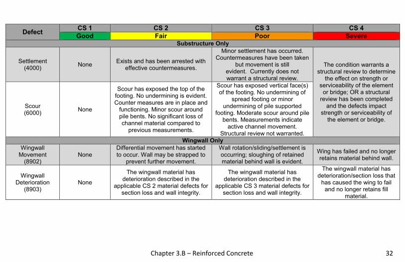
Chapter 3.B – Reinforced Concrete 32
Defect CS 1 CS 2 CS 3 CS 4
Good Fair Poor Severe Substructure Only
Settlement (4000)
None Exists and has been arrested with
effective countermeasures.
Minor settlement has occurred. Countermeasures have been taken
but movement is still evident. Currently does not warrant a structural review.
The condition warrants a structural review to determine
the effect on strength or serviceability of the element
or bridge; OR a structural review has been completed
and the defects impact strength or serviceability of
the element or bridge.
Scour (6000)
None
Scour has exposed the top of the footing. No undermining is evident. Counter measures are in place and
functioning. Minor scour around pile bents. No significant loss of channel material compared to
previous measurements.
Scour has exposed vertical face(s) of the footing. No undermining of
spread footing or minor undermining of pile supported
footing. Moderate scour around pile bents. Measurements indicate
active channel movement. Structural review not warranted.
Wingwall Only
Wingwall Movement
(8902) None
Differential movement has started to occur. Wall may be strapped to
prevent further movement.
Wall rotation/sliding/settlement is occurring; sloughing of retained material behind wall is evident.
Wing has failed and no longer retains material behind wall.
Wingwall Deterioration
(8903) None
The wingwall material has deterioration described in the
applicable CS 2 material defects for section loss and wall integrity.
The wingwall material has deterioration described in the
applicable CS 3 material defects for section loss and wall integrity.
The wingwall material has deterioration/section loss that
has caused the wing to fail and no longer retains fill
material.
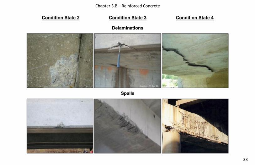
Chapter 3.B – Reinforced Concrete
33
Condition State 2 Condition State 3 Condition State 4
Delaminations
Spalls

Chapter 3.B – Reinforced Concrete 34
Condition State 2 Condition State 3 Condition State 4
Exposed Rebar
Cracking – Reinforced Concrete

Chapter 3.B – Reinforced Concrete
35
Condition State 2 Condition State 3 Condition State 4
Abrasion/Wear
Settlement
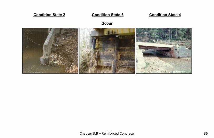
Chapter 3.B – Reinforced Concrete 36
Condition State 2 Condition State 3 Condition State 4
Scour

Chapter 3.C – Reinforced Concrete
37
THIS PAGE IS INTENTIONALLY LEFT BLANK

Chapter 3.C – Prestressed Concrete 38
Chapter 3.C Prestressed Concrete

Chapter 3.C – Reinforced Concrete
39
C. Prestressed Concrete
Deck
13 – Prestressed Concrete Deck SF
15 – Prestressed Concrete Top Flange SF
8039 – Prestressed Concrete Slab SF Superstructure
104 – Prestressed Concrete Closed Web/Box Girder
LF
109 – Prestressed Concrete Open Girder/Beam LF
115 – Prestressed Concrete Stringer LF
143 – Prestressed Concrete Arch LF
154 – Prestressed Concrete Floor Beam LF
**The inspector should use judgment when utilizing condition state defect definitions; considering concrete crack type, location, and orientation.
Where required, an In-Depth inspection may need to be scheduled so that proper equipment, cleaning, access, traffic control, etcK can be
mobilized to assess and properly document any defect’s condition state.
Substructure
204 – Prestressed Concrete Column EA
226 – Prestressed Concrete Pile EA
233 – Prestressed Concrete Cap LF
8400 – Integral Wingwall EA
Culvert
245 – Prestressed Concrete Culvert LF Other
320 – Prestressed Concrete Structural Approach Slab
SF
8170 – Other Primary Structural Members LF
Concrete Cracks Concrete Scale/Abrasion/Wear
Prestressed
Hairline <.004” Light Scale ¼” Deep
Narrow .004” to .009” Medium Scale ¼” to ½” Deep
Medium .01” to .03” Heavy Scale ½” to 1” Deep
Wide >.03” Severe Scale Loss of aggregate

Chapter 3.C – Prestressed Concrete 40
Narrative:
• Concerns with exposed reinforcing of concrete elements are less severe than that of exposed prestressing. Deterioration and damage to regular reinforcement (mild steel) should be documented and most likely addressed with a feasible action and is less critical than similar deficiencies to prestressing due to a lack of significant tension in the steel. Similarly, the crack sizes identified in the condition state definitions of the two materials also differ.
• Wear is the removal of deck surface aggregate by repeated vehicular traffic.
• Abrasion is the removal of cement paste and/or surface aggregate on piers/bents in rivers from water/sediment/ice flows. Abrasion can also occur in the flow line on top of the bridge deck. It will be noted at the extreme edge of the deck surface and the lower 2” to 3” of the concrete parapet wall.
• All prestressed concrete decks will be evaluated from the sides and underside of the deck. The top of the deck will be evaluated with the respective wearing surface. Prestressed concrete decks without a wearing surface will have the top of the deck evaluated under Element 8000 – Wearing Surface (Bare).
• Element 8039 – Prestressed Concrete Slab: Examples of elements that should be coded under these elements include solid prestressed slabs, hollow core prestressed slabs, inverted prestressed T-beams, etc.
• If condition warrants analysis, indicate in the notes why re-rating should be done.
• Chloride Concentration (8905) to be used only on those bridges in a chloride testing program. Refer to the Structure Inspection Manual
for current chloride concentration vs. active corrosion threshold.
• Patched areas in defect 1080 include structural patches only. Temporary maintenance patches, such as asphalt, will be considered
unsound patches.
• Culvert distortion defects will be coded through the defect ‘Settlement’.
• Both Elements 320 and 321 are for structural approach slabs only. Non-structural approach slabs will be coded under the applicable
Assessment. Structural approach slabs will have one end resting on the abutment paving notch, and the other end resting on a grade
beam.

Chapter 3.C – Prestressed Concrete
41
Defect CS 1 CS 2 CS 3 CS 4
Good Fair Poor Severe
Delaminations/ Spalls/Patch
Areas (1080)
None
Delaminated. Spall 1 in. or less deep or less than 6 in.
diameter. Patched area that is sound.
Spall greater than 1 in. deep or greater than 6 in. diameter.
Patched area that is unsound or showing distress. Does not warrant structural review.
The condition warrants a structural review to determine
the effect on strength or serviceability of the element or bridge; OR a structural review has been completed and the defects impact strength or
serviceability of the element or bridge.
Exposed Prestressing
(1100) None Present without section loss.
Present with section loss that does not warrant structural review.
Cracking (PSC) (1110)
Width less than 0.004 in. or sealed
cracks.
Width 0.004 – 0.009 in. Where efflorescence is present, it’s
minor and no evidence of rust staining.
Width greater than 0.009 in. Where efflorescence is present, there is
heavy build-up and/or rust staining.
Abrasion/Wear (PSC/RC)
(1190) No abrasion
Abrasion has exposed coarse aggregate but the aggregate
remains secure in the concrete.
Coarse aggregate is loose or has popped out of the concrete matrix
due to abrasion.
Chloride
Concentration
(8905)
Chloride
concentration at
level of rebar tested
below the threshold
for potential active
corrosion.
Chloride concentration at level
of rebar tested equal to or
greater than the threshold for
potential active steel corrosion.
No visual signs of active
corrosion exist.
Chloride concentration at level of
rebar tested greater than the
threshold for potential active steel
corrosion. Testing methods (such
as half-cell potential) have been
used and have verified active steel
corrosion.
Not used for this defect. Other
reinforced or prestressed
concrete defects control the
Condition State over chloride
concentrations (elevated levels
of chloride concentrations may
be cause of controlling
defects).
Precast Concrete Connections
(8906) None
Minor cracking at the joints. Connection is functioning as
intended.
Cracking and/or spalling at the joints. No displacement is evident.
Connection is failing or has failed. Condition warrants
structural analysis.
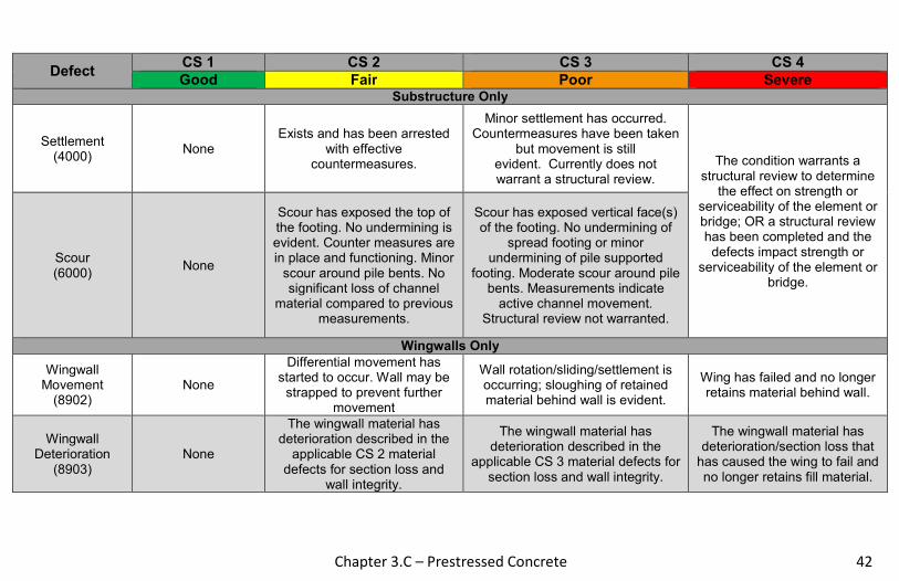
Chapter 3.C – Prestressed Concrete 42
Defect CS 1 CS 2 CS 3 CS 4
Good Fair Poor Severe Substructure Only
Settlement (4000)
None Exists and has been arrested
with effective countermeasures.
Minor settlement has occurred. Countermeasures have been taken
but movement is still evident. Currently does not warrant a structural review.
The condition warrants a structural review to determine
the effect on strength or serviceability of the element or bridge; OR a structural review has been completed and the defects impact strength or
serviceability of the element or bridge.
Scour (6000)
None
Scour has exposed the top of the footing. No undermining is evident. Counter measures are in place and functioning. Minor
scour around pile bents. No significant loss of channel
material compared to previous measurements.
Scour has exposed vertical face(s) of the footing. No undermining of
spread footing or minor undermining of pile supported
footing. Moderate scour around pile bents. Measurements indicate
active channel movement. Structural review not warranted.
Wingwalls Only
Wingwall Movement
(8902) None
Differential movement has started to occur. Wall may be
strapped to prevent further movement
Wall rotation/sliding/settlement is occurring; sloughing of retained material behind wall is evident.
Wing has failed and no longer retains material behind wall.
Wingwall Deterioration
(8903) None
The wingwall material has deterioration described in the
applicable CS 2 material defects for section loss and
wall integrity.
The wingwall material has deterioration described in the
applicable CS 3 material defects for section loss and wall integrity.
The wingwall material has deterioration/section loss that
has caused the wing to fail and no longer retains fill material.

Chapter 3.C – Prestressed Concrete
43
Condition State 2 Condition State 3 Condition State 4
Delaminations
Spalls

Chapter 3.C – Prestressed Concrete 44
Condition State 2 Condition State 3 Condition State 4
Exposed Prestressing
Cracking – Prestressed

Chapter 3.C – Prestressed Concrete
45
Condition State 2 Condition State 3 Condition State 4
Abrasion/Wear
Settlement

Chapter 3.C – Prestressed Concrete 46
Condition State 2 Condition State 3 Condition State 4
Scour

Chapter 3.D – Timber
47
THIS PAGE IS INTENTIONALLY LEFT BLANK

Chapter 3.D – Timber 48
Chapter 3.D Timber
Chapter 3.D – Timber
49
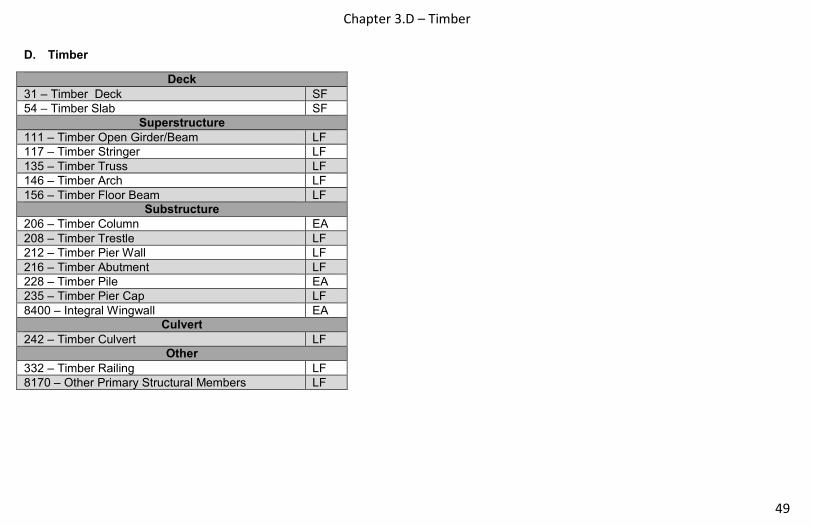
D. Timber
Deck
31 – Timber Deck SF
54 – Timber Slab SF
Superstructure
111 – Timber Open Girder/Beam LF
117 – Timber Stringer LF
135 – Timber Truss LF
146 – Timber Arch LF
156 – Timber Floor Beam LF Substructure
206 – Timber Column EA
208 – Timber Trestle LF
212 – Timber Pier Wall LF
216 – Timber Abutment LF
228 – Timber Pile EA
235 – Timber Pier Cap LF
8400 – Integral Wingwall EA Culvert
242 – Timber Culvert LF Other
332 – Timber Railing LF
8170 – Other Primary Structural Members LF

Chapter 3.D – Timber 50
Narrative:
• Delaminations in timber members are generally found in glue and stress laminated members. Glue laminated timber members should
be checked for delamination as the load carrying capacity could be affected. If delamination is noted in stress laminated members, the
adjacent post-tensioning rods/bolts should be checked to verify adequate tension.
• All timber decks will be evaluated from the sides and underside of the deck. The top of the deck will be evaluated with the respective wearing surface. Timber decks without a wearing surface will have the top of the deck evaluated under Element 8000 – Wearing Surface (Bare).
• Timber decay is most likely to occur in any areas of wetting and drying, at soil lines and water lines, flat areas that collect water,
particularly where dirt and other debris is built up, and areas where the protective system, if present, is ineffective.
• Insect infestation can also be the cause of timber section loss and would be evaluated under Defect 1140.
• Element 208 is to be used for truss framed trestle or towers. This element is intended to capture large supports and towers associated
with large deck truss bridges.
• The deck or slab may be longitudinally or transversely laminated, or constructed of planks, and may or may not be constructed with
spreader beams or runners of metal or wood. Report the condition state that represents the condition of the bottom and sides of
element.
• If condition warrants analysis, indicate in the notes why or why not re-rating should be done.
Chapter 3.D – Timber
51
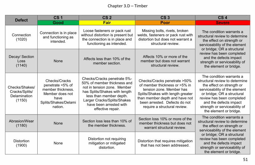
Defect CS 1 CS 2 CS 3 CS 4
Good Fair Poor Severe
Connection (1020)
Connection is in place and functioning as
intended.
Loose fasteners or pack rust without distortion is present but the connection is in place and
functioning as intended.
Missing bolts, rivets, broken welds, fasteners or pack rust with distortion but does not warrant a
structural review.
The condition warrants a
structural review to determine the effect on strength or
serviceability of the element or bridge; OR a structural
review has been completed and the defects impact
strength or serviceability of the element or bridge.
Decay/ Section Loss
(1140) None
Affects less than 10% of the member section.
Affects 10% or more of the member but does not warrant
structural review.
Checks/Shakes/ Cracks/Splits/ Delamination
(1150)
Checks/Cracks penetrate <5% of
member thickness. Member does not
have Splits/Shakes/Delami
nation.
Checks/Cracks penetrate 5%-50% of member thickness and not in tension zone. Member has Splits/Shakes with length
less than member depth. Larger Cracks/Splits/Shakes
have been arrested with effective repair.
Checks/Cracks penetrate >50% of member thickness or >5% in
tension zone. Member has Splits/Shakes with length greater than member depth and have not
been arrested. Defects do not require a structural review.
The condition warrants a structural review to determine
the effect on strength or serviceability of the element
or bridge; OR a structural review has been completed
and the defects impact strength or serviceability of
the element or bridge.
Abrasion/Wear (1180)
None Section loss less than 10% of
the member thickness.
Section loss 10% or more of the member thickness but does not
warrant structural review.
The condition warrants a structural review to determine
the effect on strength or serviceability of the element
or bridge; OR a structural review has been completed
and the defects impact strength or serviceability of
the element or bridge.
Distortion (1900)
None Distortion not requiring mitigation or mitigated
distortion.
Distortion that requires mitigation that has not been addressed.

Chapter 3.D – Timber 52
Defect CS 1 CS 2 CS 3 CS 4
Good Fair Poor Severe Substructure Only
Settlement (4000)
None Exists and has been arrested
with effective countermeasures.
Minor settlement has occurred. Countermeasures have been taken but movement is still evident. Currently does not warrant a structural review.
The condition warrants a structural review to determine
the effect on strength or serviceability of the element
or bridge; OR a structural review has been completed
and the defects impact strength or serviceability of
the element or bridge.
Scour (6000)
None
Scour has exposed the top of the footing. No undermining is evident. Counter measures are in place and functioning. Minor
scour around pile bents. No significant loss of channel
material compared to previous measurements.
Scour has exposed vertical face(s) of the footing. No
undermining of spread footing or minor undermining of pile
supported footing. Moderate scour around pile bents.
Measurements indicate active channel movement. Structural
review not warranted.
Wingwalls Only
Wingwall Movement
(8902) None
Differential movement has started to occur. Wall may be
strapped to prevent further movement.
Wall rotation/sliding/settlement is occurring; sloughing of retained material behind wall is evident.
Wing has failed and no longer retains material behind wall.
Wingwall Deterioration
(8903) None
The wingwall material has deterioration described in the
applicable CS 2 material defects for section loss and
wall integrity.
The wingwall material has deterioration described in the
applicable CS 3 material defects for section loss and wall integrity.
The wingwall material has deterioration/section loss that
has caused the wing to fail and no longer retains fill
material.

Chapter 3.D – Timber
53
Condition State 2 Condition State 3 Condition State 4
Connection
Decay/Section Loss

Chapter 3.D – Timber 54
Condition State 2 Condition State 3 Condition State 4
Checks/Shakes
Cracks

Chapter 3.D – Timber
55
Condition State 2 Condition State 3 Condition State 4
Splits/Delaminations
Abrasion/Wear

Chapter 3.D – Timber 56
Condition State 2 Condition State 3 Condition State 4
Wear
Settlement

Chapter 3.D – Timber
57
Condition State 2 Condition State 3 Condition State 4
Scour

Chapter 3.E – Masonry 58
E. Masonry
Superstructure
145 – Masonry Arch LF Substructure
213 – Masonry Pier Wall LF
217 – Masonry Abutment LF
8400 – Integral Wingwall EA
Culvert
244 – Masonry Culvert LF
Other
334 – Masonry Bridge Railing LF
8170 – Other Primary Structural Members LF
Narrative:
• Faux masonry elements (i.e. precast concrete blocks,
reinforced concrete blocks, etc.) will not be rated under
this set of elements. These types of material will be rated
under “Other Materials”.
• If condition warrants analysis, indicate in the notes why or
why not re-rating should be done.
Chapter 3.E – Masonry
59
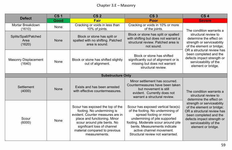
Defect CS 1 CS 2 CS 3 CS 4
Good Fair Poor Severe Mortar Breakdown
(1610) None
Cracking or voids in less than 10% of joints.
Cracking or voids in 10% or more of the joints.
The condition warrants a structural review to
determine the effect on strength or serviceability of the element or bridge;
OR a structural review has been completed and the
defects impact strength or serviceability of the element or bridge.
Splits/Spall/Patched Area
(1620) None
Block or stone has split or spalled with no shifting. Patched
area is sound.
Block or stone has split or spalled with shifting but does not warrant a structural review. Patched area is
not sound.
Masonry Displacement (1640)
None Block or stone has shifted slightly
out of alignment.
Block or stone has shifted significantly out of alignment or is
missing but does not warrant structural review.
Substructure Only
Settlement (4000)
None Exists and has been arrested
with effective countermeasures.
Minor settlement has occurred. Countermeasures have been taken
but movement is still evident. Currently does not warrant a structural review.
The condition warrants a structural review to
determine the effect on strength or serviceability of the element or bridge;
OR a structural review has been completed and the
defects impact strength or serviceability of the element or bridge.
Scour (6000)
None
Scour has exposed the top of the footing. No undermining is
evident. Counter measures are in place and functioning. Minor scour around pile bents. No significant loss of channel
material compared to previous measurements.
Scour has exposed vertical face(s) of the footing. No undermining of
spread footing or minor undermining of pile supported
footing. Moderate scour around pile bents. Measurements indicate
active channel movement. Structural review not warranted.

Chapter 3.E – Masonry 60
Defect CS 1 CS 2 CS 3 CS 4
Good Fair Poor Severe Wingwalls Only
Wingwall Movement (8902)
None
Differential movement has started to occur. Wall may be
strapped to prevent further movement.
Wall rotation/sliding/settlement is occurring; sloughing of retained material behind wall is evident.
Wing has failed and no longer retains material
behind wall.
Wingwall Deterioration (8903)
None
The wingwall material has deterioration described in the
applicable CS 2 material defects for section loss and wall integrity.
The wingwall material has deterioration described in the
applicable CS 3 material defects for section loss and wall integrity.
The wingwall material has deterioration/section loss that has caused the wing
to fail and no longer retains fill material.

Chapter 3.E – Masonry
61
Condition State 2 Condition State 3 Condition State 4
Spalls/Delaminations/Patch Areas
Mortar Breakdown
Chapter 3.E – Masonry 62
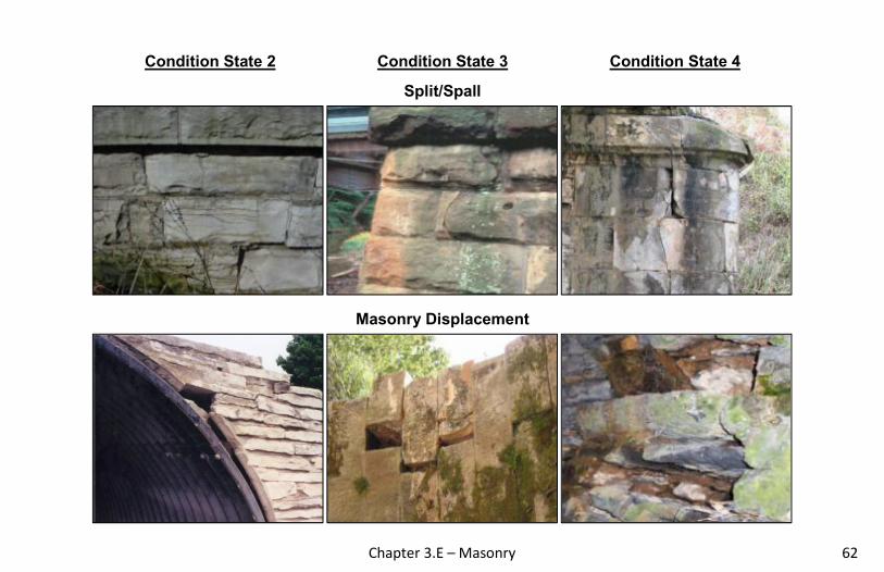
Condition State 2 Condition State 3 Condition State 4
Split/Spall
Masonry Displacement

Chapter 3.E – Masonry
63
Condition State 2 Condition State 3 Condition State 4
Settlement
Scour

Chapter 3.F – Other Materials 64
F. Other Materials
Deck
60 – Other Material Deck SF
65 – Other Material Slab SF
Superstructure
106 – Other Material Closed Web/Box Girder LF
112 – Other Material Open Girder/Beam LF
118 – Other Material Stringer LF
136 – Other Material Truss LF
142 – Other Material Arch LF
157 – Other Material Floor Beam LF Substructure
203 – Other Material Column EA
211 – Other Material Pier Wall LF
218 – Other Material Abutment LF
229 – Other Material Pile EA
8400 – Integral Wingwall EA
Culvert
243 – Other Material Culvert LF
Other
333 – Other Material Bridge Railing LF
8170 – Other Primary Structural Members LF
Narrative:
• Elements constructed of materials not already identified
should use the “Other” category in order to capture their
quantity and condition. Examples of this may include FRP
or other plastics, aluminum, or stainless steel.
• GRS and Prestressed abutments are included in (218)
Other Abutments.
• If condition warrants analysis, indicate in the notes why or
why not re-rating should be done.
• Element 243 – Other Material Culvert includes plastic,
aluminum, and composite culverts

Chapter 3.F – Other Materials
65
Defect CS 1 CS 2 CS 3 CS 4
Good Fair Poor Severe
Corrosion (1000)
None Freckled rust. Corrosion of
the steel has initiated.
Section loss is evident or pack rust is present but does not warrant structural review.
The condition warrants a structural review to
determine the effect on strength or serviceability of the element or bridge;
OR a structural review has been completed and the
defects impact strength or serviceability of the element or bridge.
Cracking (1010)
None
Crack that has self arrested or has been arrested with
effective arrest holes, doubling plates, or similar.
Identified crack exists that is not arrested but does not warrant
structural review.
Connection (1020)
Connection is in place and
functioning as intended.
Loose fasteners or pack rust without distortion is present
but the connection is in place and functioning as
intended.
Missing bolts, rivets, broken welds, fasteners or pack rust with distortion but does not warrant a structural review.
Delaminations/Spalls/ Patch Areas
(1080) None
Delaminated. Spall 1 in. or less deep or less than 6 in. diameter. Patched area that
is sound.
Spall greater than 1 in. deep or greater than 6 in. diameter.
Patched area that is unsound or showing distress. Does not warrant structural review.
Deterioration (1220)
None Initiated breakdown or
deterioration.
Significant deterioration or breakdown, but does not warrant
a structural review.
Distortion (1900)
None Distortion not requiring mitigation or mitigated
distortion.
Distortion that requires mitigation that has not been
addressed.
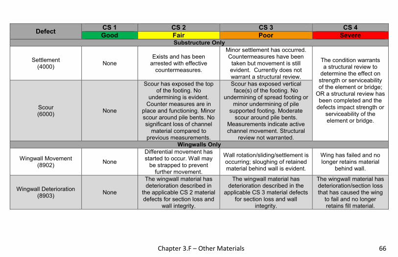
Chapter 3.F – Other Materials 66
Defect CS 1 CS 2 CS 3 CS 4
Good Fair Poor Severe
Substructure Only
Settlement (4000)
None Exists and has been
arrested with effective countermeasures.
Minor settlement has occurred. Countermeasures have been
taken but movement is still evident. Currently does not warrant a structural review.
The condition warrants a structural review to
determine the effect on strength or serviceability of the element or bridge;
OR a structural review has been completed and the
defects impact strength or serviceability of the element or bridge.
Scour (6000)
None
Scour has exposed the top of the footing. No
undermining is evident. Counter measures are in
place and functioning. Minor scour around pile bents. No significant loss of channel
material compared to previous measurements.
Scour has exposed vertical face(s) of the footing. No
undermining of spread footing or minor undermining of pile
supported footing. Moderate scour around pile bents.
Measurements indicate active channel movement. Structural
review not warranted. Wingwalls Only
Wingwall Movement (8902)
None
Differential movement has started to occur. Wall may
be strapped to prevent further movement.
Wall rotation/sliding/settlement is occurring; sloughing of retained material behind wall is evident.
Wing has failed and no longer retains material
behind wall.
Wingwall Deterioration (8903)
None
The wingwall material has deterioration described in
the applicable CS 2 material defects for section loss and
wall integrity.
The wingwall material has deterioration described in the
applicable CS 3 material defects for section loss and wall
integrity.
The wingwall material has deterioration/section loss that has caused the wing
to fail and no longer retains fill material.

Chapter 3.F – Other Materials
67
THIS PAGE IS INTENTIONALLY LEFT BLANK

Chapter 3.G – Bearings 68
G. Bearings
Narrative:
• The primary concern with bearings is their ability to function as designed; to allow for expansion, contraction and rotation of the bridge
superstructure. Inspectors should look at the alignment of the joints and bridge rail for indications that the bearings are not functioning
properly. The mechanical functionality and condition of the bearings is also considered. Measurements of movement and displacement
are often necessary for a complete evaluation.
• The loads are transferred through the bearings from the superstructure elements into the substructure. Deficiencies in the
superstructure and substructure can also result from issues with the performance and functionality of the bearings.
• The bulging, splitting, or tearing defect is only used for elastomeric and pot bearings.
• Bearings should only be reported if visible.
• Element 310 includes elastomeric and laminated bearing pads, but not thin, non-laminated bearing pads.
• Element 311 includes rocker bearings, roller bearings, sliding bearings etc.
• Element 314 & 315 are primarily used on large structures and railroad bridges.
• A bridge with the girders cast into the end diaphragms will have no bearings reported, since bearings are not visible.
310 – Elastomeric Bearing EA
311 – Moveable Bearing EA
313 – Fixed Bearing EA
314 – Pot Bearing EA
315 – Disc Bearing EA
316 – Other Bearing EA

Chapter 3.G – Bearings
69
Bearing Types
310 – Elastomeric Bearing 311 – Movable Bearing 313 – Fixed Bearing
314 – Pot Bearing 315 – Disc Bearing

Chapter 3.G – Bearings 70
Defect CS 1 CS 2 CS 3 CS 4
Good Fair Poor Severe
Corrosion (1000)
None. Freckled Rust. Corrosion of
the steel has initiated.
Section loss is evident or pack rust is present but does not warrant structural review.
The condition warrants a structural review to
determine the effect on strength or serviceability of the element or bridge;
OR a structural review has been completed and the
defects impact strength or serviceability of the element or bridge.
Connection (1020)
Connection is in place and functioning as
intended.
Loose fasteners or pack rust without distortion is present but the connection is in place and
functioning as intended.
Missing bolts, rivets, broken welds, fasteners or pack rust with distortion but does not warrant a structural review.
Movement (2210)
Free to move. Minor restriction. Restricted but not warranting
structural review.
Alignment (2220)
Lateral and vertical alignment is as expected for the
temperature conditions.
Tolerable lateral or vertical alignment that is inconsistent
with the temperature conditions.
Approaching the limits of lateral or vertical alignment for the
bearing but does not warrant a structural review.
Bulging, Splitting, or Tearing
(2230) None.
Bulging less than 15% of the thickness.
Bulging 15% or more of the thickness. Splitting or tearing.
Bearing's surfaces are not parallel. Does not warrant
structural review.
Loss of Bearing Area (2240)
None. Less than 10%. 10% or more but does not warrant structural review.

Chapter 3.G – Bearings
71
Condition State 2 Condition State 3 Condition State 4
Corrosion
Connection

Chapter 3.G – Bearings 72
Condition State 2 Condition State 3 Condition State 4
Movement
Alignment

Chapter 3.G – Bearings
73
Condition State 2 Condition State 3 Condition State 4
Bulging/Splitting/Tearing
Loss of Bearing Area
Chapter 3.H - Joints 74
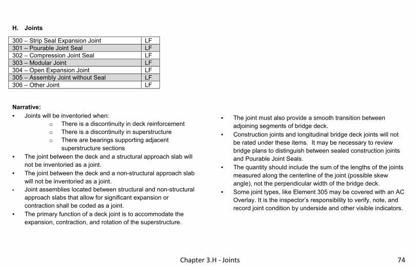
H. Joints
300 – Strip Seal Expansion Joint LF
301 – Pourable Joint Seal LF
302 – Compression Joint Seal LF
303 – Modular Joint LF
304 – Open Expansion Joint LF
305 – Assembly Joint without Seal LF
306 – Other Joint LF
Narrative:
• Joints will be inventoried when:
o There is a discontinuity in deck reinforcement
o There is a discontinuity in superstructure
o There are bearings supporting adjacent
superstructure sections
• The joint between the deck and a structural approach slab will
not be inventoried as a joint.
• The joint between the deck and a non-structural approach slab
will not be inventoried as a joint.
• Joint assemblies located between structural and non-structural
approach slabs that allow for significant expansion or
contraction shall be coded as a joint.
• The primary function of a deck joint is to accommodate the
expansion, contraction, and rotation of the superstructure.
• The joint must also provide a smooth transition between
adjoining segments of bridge deck.
• Construction joints and longitudinal bridge deck joints will not
be rated under these items. It may be necessary to review
bridge plans to distinguish between sealed construction joints
and Pourable Joint Seals.
• The quantity should include the sum of the lengths of the joints
measured along the centerline of the joint (possible skew
angle), not the perpendicular width of the bridge deck.
• Some joint types, like Element 305 may be covered with an AC
Overlay. It is the inspector’s responsibility to verify, note, and
record joint condition by underside and other visible indicators.

Chapter 3.H - Joints
75
Joint Types
300 - Strip Seal Expansion Joint 301 - Pourable Joint Seal 302 - Compression Joint Seal
303 - Modular Joint 304 - Open Expansion Joint 305 - Assembly Joint without Seal

Chapter 3.H – Joints 76
Defect CS 1 CS 2 CS 3 CS 4
Good Fair Poor Severe
Leakage, Seal Adhesion/
Damage/ Cracking (2310)
Fully Adhered.
Minimal leakage minor dripping through the joint.
Seal adhered for more than 50% of the joint height. Seal
abrasion without through punctures/cracks.
Moderate leakage. Seal adhered 50% or less of joint
height but still some adhesion. Punctured,
cracked, or ripped or partially pulled out.
Free flow of water through the joint. Complete loss of
seal adhesion. Punctured/cracked/teared completely through, pulled
out, or missing.
Debris Impaction (2350)
No debris to a shallow cover of loose debris
may be evident but does not affect the
performance of the joint.
Partially filled with hard-packed material, but still allowing free movement.
Completely filled and impacts joint movement.
Completely filled and prevents joint movement.
Adjacent Deck or Header/
Metal Deterioration or Damage
(2360)
Sound.
Edge delamination or spall 1 in. or less deep, or 6 in. or
less in diameter. No exposed rebar. Patched
area that is sound. Freckled rust, metal has no cracks, or impact damage. Connection may be loose but functioning
as intended.
Spall greater than 1 in. deep or greater than 6 in.
diameter. Exposed rebar. Delamination or unsound
patched area that makes the joint loose. Section loss,
missing or broken fasteners, cracking of the metal or
impact damage but joint still functioning.
Spall, delamination, unsound patched area or
loose joint anchor that prevents the joint from
functioning as intended. Metal cracking, section loss,
damage or connection failure that prevents the joint
from functioning as intended.

Chapter 3.H - Joints
77
Condition State 2 Condition State 3 Condition State 4
Leakage/Seal Adhesion/Damage/Cracking
Debris Impaction

Chapter 3.H – Joints 78
Condition State 2 Condition State 3 Condition State 4
Adjacent Deck or Header/Metal Deterioration or Damage

Chapter 3.H - Joints
79
THIS PAGE IS INTENTIONALLY LEFT BLANK

Chapter 3.I – Steel Protective Coatings 80
I. Steel Protective Coatings
515 – Steel Protective Coating - Other SF
8516 – Painted Steel SF
8517 – Weathering Steel SF
8518 – Galvanization SF
8519 – Duplex Systems SF
Narrative:
• Elements 515, 8516, 8517, 8518, and 8519 allow for a
detailed and thorough evaluation of various steel
protective coatings. The defect definitions allow for the
evaluation of the protective system itself regardless of the
condition of the element it protects.
• The presence of lead paint is possible and should be
considered when performing inspections. Any feasible
actions for paint systems should also identify the presence
of lead paint.
• Steel Protective Coatings will be calculated for all steel superstructure elements, as well as primary steel substructure elements (pier caps, columns, towers, and abutments).
• Elements 515, 8516, 8518, and 8519 will only be evaluated by the defect Effectiveness (3440).
• Element 8517 will only be evaluated by the defect Oxide Film Degradation/Color/Texture Adherence (3430).

Chapter 3.I – Steel Protective Coatings
81
Defect CS 1 CS 2 CS 3 CS 4
Good Fair Poor Severe
Oxide Film Degradation/ Color/ Texture Adherence –
Weathering Steel (3430)
Yellow-orange or light brown for early development.
Chocolate-brown to purple-brown for fully developed. Tightly adhered, capable of
withstanding hammering or vigorous wire
brushing.
Granular texture. Small flakes, less than
1/2 in. diameter.
Dark black color. Large flakes, 1/2 in. diameter or greater or laminar sheets or nodules.
Effectiveness (3440)
Fully effective
Substantially effective. Surface dulling.
Peeling, bubbling, or cracking to finish coat
only.
Limited effectiveness. Loss of pigment.
Peeling, bubbling, or cracking to finish and
primer coats.
Failed, no protection of the underlying metal.

Chapter 3.I – Steel Protective Coatings 82
Condition State 2 Condition State 3 Condition State 4
Oxide Film Degradation/ Texture Adherence
Effectiveness

Chapter 3.I – Steel Protective Coatings
83
THIS PAGE IS INTENTIONALLY LEFT BLANK
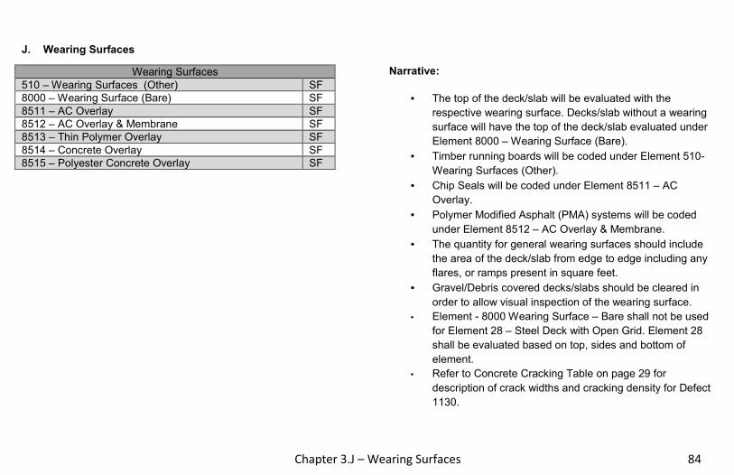
Chapter 3.J – Wearing Surfaces 84
J. Wearing Surfaces
Wearing Surfaces
510 – Wearing Surfaces (Other) SF
8000 – Wearing Surface (Bare) SF
8511 – AC Overlay SF
8512 – AC Overlay & Membrane SF
8513 – Thin Polymer Overlay SF
8514 – Concrete Overlay SF
8515 – Polyester Concrete Overlay SF
Narrative:
• The top of the deck/slab will be evaluated with the
respective wearing surface. Decks/slab without a wearing
surface will have the top of the deck/slab evaluated under
Element 8000 – Wearing Surface (Bare).
• Timber running boards will be coded under Element 510-
Wearing Surfaces (Other).
• Chip Seals will be coded under Element 8511 – AC
Overlay.
• Polymer Modified Asphalt (PMA) systems will be coded
under Element 8512 – AC Overlay & Membrane.
• The quantity for general wearing surfaces should include
the area of the deck/slab from edge to edge including any
flares, or ramps present in square feet.
• Gravel/Debris covered decks/slabs should be cleared in
order to allow visual inspection of the wearing surface.
• Element - 8000 Wearing Surface – Bare shall not be used
for Element 28 – Steel Deck with Open Grid. Element 28
shall be evaluated based on top, sides and bottom of
element.
• Refer to Concrete Cracking Table on page 29 for
description of crack widths and cracking density for Defect
1130.

Chapter 3.J – Wearing Surfaces
85
Defect CS 1 CS 2 CS 3 CS 4
Good Fair Poor Severe Wearing Surfaces
Debonding/Spall/ Patched Area/Pothole – Wearing
Surface (3210)
None
Debonding. Spalls 1 in. or less deep or less
than 6 in. in diameter. Patched areas that are sound. Partial depth
potholes.
Spalls greater than 1 in. deep or greater than 6 in. in diameter. Patched areas
that are unsound or showing distress. Full depth
potholes. The wearing surface is no longer
effective.
Crack – Wearing Surface (3220)
No cracks. Hairline cracks not requiring sealing, or cracks
that have been sealed.
Unsealed cracks of narrow width, or
unsealed minor to moderate pattern/map
cracking.
Unsealed cracks of medium to wide width, or extensive
patterns/map cracking.
Abrasion, Wear, Rutting, or Loss of Friction –
Wearing Surface (8911)
None
Minimal loss of surface material in wheel paths.
No significant loss of friction has occurred.
Asphalt overlay exhibiting minor isolated
rutting.
Loss of surface material has become prevalent in the
wheel paths. Loss of friction is noticeable. Asphalt
overlay has moderate to severe isolated rutting.
Loss of surface material is widespread throughout
overlay. Loss of friction is prevalent and potentially
dangerous in adverse weather conditions. Asphalt overlay has significant rutting throughout the
length of structure.

Chapter 3.J – Wearing Surfaces 86
Condition State 2 Condition State 3 Condition State 4
Debonding/Spall/Patched Area/Potholes
Cracks, Concrete or Epoxy

Chapter 3.J – Wearing Surfaces
87
Condition State 2 Condition State 3 Condition State 4
Cracks, Asphalt

Chapter 3.K – Reinforcing Steel Protective Systems 88
K. Concrete Reinforcing Steel Protective Systems
Concrete Reinforcing Steel Protective Systems
520 – Concrete Reinforcing Steel Protective System (Other) SF
8522 – Coated Reinforcing SF
8523 – Stainless Steel Reinforcing SF
8524 – Non-metallic Reinforcing SF
Narrative:
• Element 520 refers to visible cathodic protection systems
only. Other coatings not visible (i.e. epoxy coated rebar)
cannot be coded.
• Elements 8522, 8523, or 8524 are under Condition State 1
until evidence of reinforcing allows the inspector to identify
and assess the coating system.
• Reinforcing protective system is used for decks only.
Reinforcing protective systems will have same area as
deck.
• On initial inspections, existing plans should be verified to
conclude reinforcing protective system used (e.g. epoxy
coated).
Defect CS 1 CS 2 CS 3 CS 4
Good Fair Poor Severe
Concrete Reinforcing Steel Protective System
Effectiveness - Protective System
(e.g. cathodic) (3600)
Fully effective Substantially effective Limited effectiveness The protective system has
failed or is no longer effective.

Chapter 3.K – Reinforcing Steel Protective Systems
89
THIS PAGE IS INTENTIONALLY LEFT BLANK
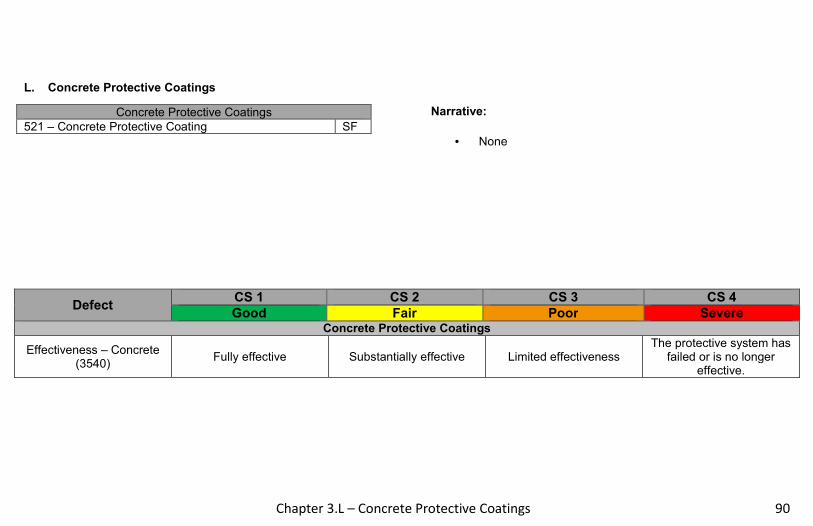
Chapter 3.L – Concrete Protective Coatings 90
L. Concrete Protective Coatings
Concrete Protective Coatings
521 – Concrete Protective Coating SF
Narrative:
• None
Defect CS 1 CS 2 CS 3 CS 4
Good Fair Poor Severe Concrete Protective Coatings
Effectiveness – Concrete (3540)
Fully effective Substantially effective Limited effectiveness The protective system has
failed or is no longer effective.
Chapter 3.L – Concrete Protective Coatings
91
THIS PAGE IS INTENTIONALLY LEFT BLANK

Chapter 3.M – Strengthening/Repair Systems 92
M. Strengthening/Repair Systems
Strengthening Systems
8800 – FRP EA
8801 – Jacketing EA
8802 – Culvert Liner LF
8803 – External Post Tensioning EA
Narrative:
• Element 8800 – FRP will consist of all strengthening
repairs made to various structural members. Examples
include girder reinforcement and column wraps.
• Element 8801 – Jacketing will consist of all jackets found
on substructure units, regardless of material
type. Examples include concrete jacket on timber column,
steel jacket on concrete column, steel jacket on timber
column, etc.
• Element 8803 – External Post Tensioning will consist of steel material.
• Refer to Concrete Cracking Table on page 29 for description of crack widths and cracking density for Defect 1130.

Chapter 3.M - Strengthening/Repair Systems
93
Defect CS 1 CS 2 CS 3 CS 4
Good Fair Poor Severe FRP and Culvert Liner Only
Deterioration (1220)
None Initiated breakdown or
deterioration.
Significant deterioration or breakdown, but does not
warrant a structural review.
The condition warrants a structural review to
determine the effect on strength or serviceability of the element or bridge; OR a structural review
has been completed and the defects impact
strength or serviceability of the element or bridge.
Distortion (1900)
None Distortion not requiring mitigation or mitigated
distortion.
Distortion that requires mitigation that has not
been addressed.
Jacketing and External Post Tensioning Only
Delaminations/Spalls/ Patch Areas
(1080) None
Delaminated. Spall 1 in. or less deep or less than 6
in. diameter. Patched area that is sound.
Spall greater than 1 in. deep or greater than 6 in. diameter. Patched area
that is unsound or showing distress. Does
not warrant structural review.
The condition warrants a structural review to
determine the effect on strength or serviceability of the element or bridge; OR a structural review
has been completed and the defects impact
strength or serviceability of the element or bridge.
Exposed Rebar (1090)
None Present without
measurable section loss.
Present with measureable section loss, but does not warrant structural review.
Cracking (RC) (1130)
No cracks. Hairline cracks not requiring sealing, or cracks
that have been sealed.
Unsealed cracks of narrow width, or unsealed
minor to moderate pattern/map cracking.
Where efflorescence is present, it’s minor with no evidence of rust staining.
Unsealed cracks of medium to wide width, or
extensive pattern map cracking. Where
efflorescence is present, there is heavy build-up
and/or rust staining.

Chapter 3.M – Strengthening/Repair Systems 94
Defect CS 1 CS 2 CS 3 CS 4
Good Fair Poor Severe
Jacketing and External Post Tensioning Only
Corrosion (1000)
None Freckled rust. Corrosion of
the steel has initiated.
Section loss is evident or pack rust is present but
does not warrant structural review.
The condition warrants a structural review to
determine the effect on strength or serviceability of the element or bridge; OR a structural review
has been completed and the defects impact
strength or serviceability of the element or bridge.
Cracking (Steel) (1010)
None
Crack that has self arrested or has been arrested with effective arrest holes, doubling
plates, or similar.
Identified crack exists that is not arrested but does not warrant structural
review.
Connection (1020)
Connection is in place and functioning as intended.
Loose fasteners or pack rust without distortion is
present but the connection is in place and functioning
as intended.
Missing bolts, rivets, broken welds, fasteners or
pack rust with distortion but does not warrant a
structural review.
Cracking (PSC) (1110)
Width less than 0.004 in. or spacing greater than 3 ft.
Without efflorescence.
Width 0.004 – 0.009 in. Where efflorescence is
present, it’s minor and no evidence of rust staining.
Width greater than 0.009 in. Where efflorescence is
present, there is heavy build-up and/or rust
staining.
Abrasion/Wear (PSC/RC) (1190)
No abrasion
Abrasion has exposed coarse aggregate but the aggregate remains secure
in the concrete.
Coarse aggregate is loose or has popped out of the concrete matrix due to
abrasion.

Chapter 3.M – Strengthening/Repair Systems
95
THIS PAGE IS INTENTIONALLY LEFT BLANK

Chapter 3.N – Wall Elements 96
N. Wall Elements
8600 – Cast in Place Concrete Wall LF
8601 – Gabion Wall LF
8602 – Gravity (Block & Rubble) Wall LF
8603 – MSE Wall LF
8604 – Post & Panel Wall LF
8605 – Sheet Pile Wall LF
8606 – Reinforced Soil Slope LF
8607 – Secant or Tangent Shaft Walls LF
8608 – Other Material Wall LF
8609 – Noise Barrier/Wall LF
Narrative:
• Earth retention elements are designed to retain soil and
can be made out of steel, concrete, timber,
masonry/stone, and other materials. Typical defects
associated with earth retention elements include scour
and settlement as well as material defects.
• A noise barrier is a constructed appurtenance, either alone
or integrated with other systems that alter the normal
noise travel at a site.
• An inspector will not typically be able to inspect tie-backs
or other types of anchorages that are located behind the
wall for stabilization. Only the front face, top, and sides of
a wall will typically be inspected during a normal
inspection.
• Non-integral wingwalls without ‘R’ numbers are considered
retaining walls. Therefore, retaining wall elements will be
used for these. Non-Integral wingwalls with ‘R’ numbers
will not be coded as part of the bridge inspection.
• The quantity for wall elements is the length of the wall in
lineal feet. All visible portions of the wall should be
considered during inspection, including all coping at the
top of the wall.
• Tipping/Sliding will be coded under the defect ‘Settlement’.
• Refer to Concrete Cracking Table on page 29 for description of crack widths and cracking density for Defect 1130.

Chapter 3.N - Wall Elements
97
Defect CS 1 CS 2 CS 3 CS 4
Good Fair Poor Severe
Corrosion (1000)
None Freckled rust. Corrosion of
the steel has initiated.
Section loss is evident or pack rust is present but does not warrant structural review.
The condition warrants a structural review to
determine the effect on strength or serviceability of the element or bridge; OR a structural review has been completed and the defects
impact strength or serviceability of the element
or bridge.
Connection (1020)
Connection is in place and
functioning as intended.
Loose fasteners or pack rust without distortion is present
but the connection is in place and functioning as intended.
Missing bolts, rivets, broken welds, fasteners or pack rust with distortion but does not warrant a
structural review
Delamination/Spalls/ Patched Areas –
Concrete (1080)
None
Delaminated. Spall 1 in. or less deep or less than 6 in. diameter. Patched area that
is sound.
Spall greater than 1 in. deep or greater than 6 in. diameter.
Patched area that is unsound or showing distress. Does not warrant structural review.
Exposed Rebar (1090)
None Present without measurable
section loss.
Present with measureable section loss, but does not warrant
structural review.
Exposed Prestressing (1100)
None Present without section loss.Present with section loss that
does not warrant structural review.
Cracking – PSC (1110)
Width less than 0.004 in.
or sealed cracks
Width 0.004 – 0.009 in. Where efflorescence is
present, it’s minor and no evidence of rust staining.
Width greater than 0.009 in. Where efflorescence is present,
there is heavy build-up and/or rust staining.
Cracking - RC (1130)
No cracks. Hairline
cracks not requiring
sealing, or cracks that have been
sealed.
Unsealed cracks of narrow width, or unsealed minor to
moderate pattern/map cracking. Where
efflorescence is present, it’s minor with no evidence of rust
staining.
Unsealed cracks of medium to wide width, or extensive pattern
map cracking. Where efflorescence is present, there is
heavy build-up and/or rust staining.

Chapter 3.N – Wall Elements 98
Defect CS 1 CS 2 CS 3 CS 4
Good Fair Poor Severe Decay/Section Loss –
Timber (1140)
None Affects less than 10% of the
member section.
Affects 10% or more of the member but does not warrant
structural review.
The condition warrants a structural review to
determine the effect on strength or serviceability of the element or bridge; OR a structural review has been completed and the defects
impact strength or serviceability of the element
or bridge.
Checks/Shakes/ Cracks/Splits/
Delamination (1150)
Checks/Cracks penetrate
<5% of member
thickness. Member does
not have Splits/Shakes.
Checks/Cracks penetrate 5%-50% of member thickness
and not in tension zone. Member has
Splits/Shakes with length less than member depth. Larger Cracks/Splits/Shakes have been arrested with effective
repair
Checks/Cracks penetrate >50% of member thickness or >5% in tension zone. Member has
Splits/Shakes with length greater than member depth and have not
been arrested. Defects do not require a structural review..
Abrasion/Wear – Timber (1180)
None Section loss less than 10% of
the member thickness.
Section loss 10% or more of the member thickness but does not
warrant structural review.
Mortar Breakdown (1610)
None Cracking or voids in less than
10% of joints. Cracking or voids in 10% or more
of the joints.
Splits/Spall/Patched Area (1620)
None Block or stone has split or
spalled with no shifting. Patched area is sound.
Block or stone has split or spalled with shifting but does not warrant a structural review. Patched area
is not sound.
Masonry Displacement (1640)
None Block or stone has shifted slightly out of alignment.
Block or stone has shifted significantly out of alignment or is
missing but does not warrant structural review.

Chapter 3.N - Wall Elements
99
Defect CS 1 CS 2 CS 3 CS 4
Good Fair Poor Severe Substructure Only
Settlement (4000)
None Exists and has been arrested
with effective countermeasures.
Minor settlement has occurred. Countermeasures have been
taken but movement is still evident. Currently does not warrant a structural review.
The condition warrants a structural review to
determine the effect on strength or serviceability of the element or bridge; OR a structural review has been completed and the defects
impact strength or serviceability of the element
or bridge.
Scour (6000)
None
Scour has exposed the top of the footing. No undermining is
evident. Counter measures are in place and functioning.
Minor scour around pile bents. No significant loss of
channel material compared to previous measurements.
Scour has exposed vertical face(s) of the footing. No
undermining of spread footing or minor undermining of pile
supported footing. Moderate scour around pile bents. Measurements
indicate active channel movement. Structural review not
warranted.
Microbial Induced Corrosion (8901)
No corrosion exists or it has been repaired
or painted over and the
water has been tested and no MIC
exists.
Water tested and MIC exists. Orange powder may exist but
little or no corrosion exists. The surface under the orange
powder may be shiny, indicating that MIC is actively attacking the steel member.
Significant section loss exists. Isolated areas of deep pitting and corrosion. Structural capacity is
not reduced. Consider recommending cleaning and
painting to help prevent further section loss.

Chapter 4 - Assessments 100
Assessments Chapter 4.
• Roadway over structure is used when there is more than 9” of fill over the culvert or deck slab.
• Approach drainage issues affecting structure, including roadway drainage flumes and catch basins adjacent to bridge within 20 feet of
wingtip should be coded.
• Sidewalk (9009) only used if raised from deck and is greater than 18 inches wide.
• The deck drainage quantity is the total of all drainage passages located on the deck.
• If median is longitudinally split, total quantity is length of split median. Do not double length.
• Utilities are allowed on bridges with a signed permit by the Maintaining Authority. The utility is required to adjust, repair or restore their
attachments if it is found that they are not being maintained properly. The Maintaining Authority should notify the Utility if deficiencies
exist and request they be corrected.
• Full height concrete diaphragms that encase the girder/beam ends and retain fill are considered part of the abutment and not coded as
an assessment.
• Full depth diaphragms above a pier are considered diaphragm assessments.
• Partial height diaphragms (> half the height of the girder/beam web) are considered diaphragms. Concrete protrusions less than half
the height of the girder/beam web are considered part of the deck.
• For a non-structural approach overlaid with asphalt, the inspector will not code the overlay, but would code the approach slab by using
Assessment 9323.
• Pavement relief joints will be assessed with Element 9322 - Approach Roadway - Concrete (non-structural).

Chapter 4 – Assessments
101
Assessments Qty Description Good Fair Poor Severe
Drainage – Approach
(9001) EA
This defines drainage systems for the approach sections of the
bridge.
Drainage systems are functioning
properly. No slope erosion is evident off
the ends of the bridge or in the
associated ditches.
Minor erosion of slopes around the bridge. Drainage
systems are plugged or have
minor deterioration.
Moderate erosion of slopes around the bridge.
Drainage systems are plugged or have moderate
deterioration.
Major erosion of bridge slopes not related to
slope protection. Drainage systems are
plugged and have major deterioration.
Drainage – Deck (9004)
EA
This defines drainage systems
for the deck sections of the
bridge.
Drainage systems are functioning properly.
Drainage systems are partially
plugged or have minor
deterioration.
Drainage systems are plugged or have moderate
deterioration.
Drainage systems are plugged and have major
deterioration.
Median (9007) EA
Use for medians. Do not use for
curbs in medians with adjacent railing as the definition for these are contained
in the railing.
No deterioration of median. Minor
cracking.
Superficial spalls and/or cracking.
Moderate deterioration such as cracking, spalling,
delaminations, etc.
Major deterioration. Reinforcement is
exposed and major spalls throughout.
Sidewalk (9009) EA
Use for sidewalks on bridge decks greater than 18”
wide. Do not use for curbs, as the
definition for these are contained in the
railing.
No deterioration of
sidewalk. Minor cracking.
Superficial spalls and/or cracking.
Moderate deterioration such as cracking, spalling,
delaminations, etc.
Major deterioration. Reinforcement is
exposed and major spalls throughout.

Chapter 4 - Assessments 102
Assessments Qty Description Good Fair Poor Severe
Aesthetic Treatments
(9010) EA
Defines the condition of the
aesthetic coating or treatment on a
bridge structure. One each per
bridge with Aesthetic
treatments.
System is in good condition, with no notable
issues.
Aesthetic system is in fair condition, with some fading or discoloration.
Minor issues.
Aesthetic system is in poor condition, with fading
or discoloration.
Aesthetic system is in severe condition and is
not functioning as intended.
Utilities (9011) EA Defines utilities that
are attached to bridge structures.
Utility is in excellent
condition, no problems
noted.
Utility is in fair condition. Some minor problems are noted, but
they do not affect the serviceability
of the utility.
Utility is in poor condition and local failures are
possible.
Utility is in severe condition. Failures have
occurred.
Movable Bridge – Counterweight
(9020) EA
Defines the condition of the counterweight
system used for movable bridges.
Counterweight is in excellent condition, no
problems noted.
Counterweight is in fair condition.
Some minor problems are
noted, but they do not affect the
serviceability of the bridge.
Counterweight is in poor condition and local failures
are possible. Serviceability of the bridge
could be affected by the items continued
deterioration.
Counterweight is in severe condition and is not functioning properly.
Movable Bridge – Cables (9021)
EA
Defines the condition of the
cables on a movable bridge.
Cables are in good condition
and are properly
functioning.
Cables are in fair condition and are
properly functioning.
Cables are in poor condition.
Cables are in severe condition, resulting in the
lifting mechanism not working properly.

Chapter 4 – Assessments
103
Assessments Qty Description Good Fair Poor Severe
Signs - Object Markers (9030)
EA
Defines the condition of bridge object markers or culvert markers.
Sign is present and is in good
condition (there may be
superficial damage or
deterioration).
Sign is present - sign may have
some damage or deterioration
(slightly bent or fading), but
remains readable.
Sign is present, but is deteriorated to the point
that replacement or repair should be considered in next inspection cycle.
Sign is absent, or incorrect, or existing sign
is damaged or deteriorated to the extent
that repair or replacement is required
as soon as possible.
Signs - Narrow Bridge (9031)
EA
Defines the condition of Narrow Bridge Signs on a Narrow Structure.
Sign is present and is in good
condition (there may be
superficial damage or
deterioration).
Sign is present - sign may have
some damage or deterioration
(slightly bent or fading), but
remains readable.
Sign is present, but is deteriorated to the point
that replacement or repair should be considered in next inspection cycle.
Sign is absent, or incorrect, or existing sign
is damaged or deteriorated to the extent
that repair or replacement is required
as soon as possible.
Signs - One Lane Bridge
(9032) EA
Defines the condition of One
Lane Bridge signs on a One Lane
Bridge.
Sign is present and is in good
condition (there may be
superficial damage or
deterioration).
Sign is present - sign may have
some damage or deterioration
(slightly bent or fading), but
remains readable.
Sign is present, but is deteriorated to the point
that replacement or repair should be considered in next inspection cycle.
Sign is absent, or incorrect, or existing sign
is damaged or deteriorated to the extent
that repair or replacement is required
as soon as possible.
Signs - Vertical Clearance
(9033) EA
Defines all vertical clearance signs
(both near bridge and advanced
warning).
Sign is present and is in good
condition (there may be
superficial damage or
deterioration).
Sign is present - sign may have
some damage or deterioration
(slightly bent or fading), but
remains readable.
Sign is present, but is deteriorated to the point
that replacement or repair should be considered in next inspection cycle.
Sign is absent, or incorrect, or existing sign
is damaged or deteriorated to the extent
that repair or replacement is required
as soon as possible.

Chapter 4 - Assessments 104
Assessments Qty Description Good Fair Poor Severe
Signs - Weight Limit Posting
(9034) EA
Defines all weight limit posting signs (both near bridge
and advanced warning).
Sign is present and is in good
condition (there may be
superficial damage or
deterioration).
Sign is present - sign may have
some damage or deterioration
(slightly bent or fading), but
remains readable.
Sign is present, but is deteriorated to the point
that replacement or repair should be considered in next inspection cycle.
Sign is absent, or incorrect, or existing sign
is damaged or deteriorated to the extent
that repair or replacement is required
as soon as possible.
Signs – Other (9035)
EA
Can be used to define signage on bridge other than what is listed in
specific sign assessment language.
Sign is present and is in good
condition (there may be
superficial damage or
deterioration).
Sign is present - sign may have
some damage or deterioration
(slightly bent or fading), but
remains readable.
Sign is present, but is deteriorated to the point
that replacement or repair should be considered in next inspection cycle.
Sign is absent, or incorrect, or existing sign
is damaged or deteriorated to the extent
that repair or replacement is required
as soon as possible.
Slope Prot. - Asphaltic (9040)
EA Defines slopes protected by
asphaltic systems.
Slope protection is sound and
protecting the embankments adjacent to the
abutments.
Minor deterioration.
Minor settlement, cracking or
spalling may exist.
Moderate deterioration. Moderate settlement,
cracking or spalling may exist.
Major deterioration of slope paving. Serious
settlement, undermining, cracking, buckling or spalling may exist.
Slope Prot. - Bare (9041)
EA Defines slopes that have no protection
systems.
Bare Slope is sound with no
erosion present.
Minor erosion present.
Moderate erosion present. Severe erosion is
present.

Chapter 4 – Assessments
105
Assessments Qty Description Good Fair Poor Severe
Slope Prot. - Concrete (9042)
EA Defines slopes protected by
concrete.
Concrete slope protection is sound and
protecting the embankments adjacent to the
abutments.
Minor deterioration.
Minor settlement, cracking or
spalling may exist.
Moderate deterioration. Moderate settlement,
cracking or spalling may exist.
Major deterioration of slope paving. Serious
settlement, undermining, cracking, buckling or spalling may exist.
Slope Prot. - Crushed
Aggregate Sprayed w/ Bit.
(9043)
EA
Defines slopes protected by
crushed aggregate sprayed w/ Bit.
Crushed aggregate is sound and
protecting the embankment
adjacent to the abutments.
Minor deterioration.
Slope may have settled. Loose
surface aggregate due to bleaching. Portions may be
missing.
Moderate deterioration. Slope has settled. Loose surface aggregate due to bleaching. Portions may
be missing.
Major deterioration. Major settlement and/or
buckling is evident.
Slope Prot. - Epoxy coated Crushed Agg
(9044)
EA
Defines slopes that are protected by Epoxy Coated
Aggregate Slope Paving.
Crushed stone is sound and protecting the embankment
adjacent to the abutments.
Minor deterioration.
Slope may have settled. Loose
surface stone due to bleaching.
Portions may be missing.
Moderate deterioration. Slope has settled. Loose
surface stone due to bleaching. Portions may
be missing.
Major deterioration. Major settlement is
evident.

Chapter 4 - Assessments 106
Assessments Qty Description Good Fair Poor Severe
Slope Prot. – Riprap (9045)
EA Defines slopes
protected by riprap.
Riprap is adequate, sound and
protecting the embankments adjacent to the
abutments.
Minor deterioration.
Slope may have settled and
portions may be missing. Riprap provides some embankment
protection.
Moderate deterioration. Slope may have settled
and portions may be missing. Riprap provides
little embankment protection.
Major deterioration. Slope has settled and portions are missing. Riprap provides no
embankment protection.
Slope Prot. - Select Crushed Material (9046)
EA Defines slopes
protected by select crushed material.
Crushed aggregate is sound and
protecting the embankment
adjacent to the abutments.
Minor deterioration.
Slope may have settled. Portions may be missing.
Moderate deterioration. Slope has settled.
Portions may be missing.
Major deterioration. Major settlement is
evident.
Slope Prot. – Other (9047)
EA
Defines other slopes not included in the specific slope
protection definitions.
Slope is sound with no erosion
present.
Minor deterioration, but
functioning effectively.
Moderate deterioration and/or erosion.
Slope protection system has failed.
Steel Diaphragm
(9167) EA
Steel diaphragm members between
girders.
Good condition.
Connections are in place
and functioning.
No distortion.
Freckled Rust. Corrosion of the
steel has initiated. Loose fasteners or pack rust without
distortion is present but the connection is functioning.
Section loss is evident or pack rust is present. Missing bolts, rivets,
broken welds, or fasteners.
The system no longer functions as intended.

Chapter 4 – Assessments
107
Assessments Qty Description Good Fair Poor Severe
Concrete Diaphragm
(9168) EA
Reinforced concrete
diaphragms.
No deterioration.
Possible discoloration, efflorescence, or superficial cracking but doesn't affect
strength or serviceability.
Minor cracks and spalls may be
present but there is no exposed reinforcing or
surface evidence of rebar corrosion.
Some delaminations &/or spalls may be present and some reinforcing may be exposed. Possible rebar corrosion but section loss is incidental and doesn’t
significantly affect strength or serviceability.
Advanced deterioration. Corrosion of
reinforcement &/or loss of concrete section is sufficient to warrant
analysis to ascertain the impact on the strength &/or serviceability of
either the element or the bridge.
Lateral Bracing (9169)
EA Lateral Bracing
System.
Good condition.
Connections are in place
and functioning.
No distortion.
Freckled Rust. Corrosion of the
steel has initiated. Loose fasteners or pack rust without
distortion is present but the connection is functioning.
Section loss is evident or pack rust is present. Missing bolts, rivets,
broken welds, or fasteners.
The system no longer functions as intended.

Chapter 4 - Assessments 108
Assessments Qty Description Good Fair Poor Severe
Culvert End Treatment
(9248) EA
This element applies to culvert
headwalls, aprons or other end
treatments (any material). The
quantity is expressed as an “each” item - on a typical culvert, the quantity will be “2” (one for each end).
Culvert end treatment has
little or no deterioration. Timber may have minor
splitting. Steel may have
minor surface corrosion.
Masonry may have minor weathering
(mortar joints are sound).
Concrete may have minor cracking or
scale.
Culvert end treatment has
minor to moderate deterioration.
Timber may have moderate splitting (minor decay or fire damage).
Steel may have moderate surface corrosion (minor
section loss). Masonry may
have moderate weathering
(mortar joints may have minor
deterioration). Concrete may have moderate
cracking or scaling (there may be
minor delamination or spalling). End treatment may
have slight undermining, settlement,
misalignment, or separation.
Culvert end treatment has extensive deterioration.
Timber may have extensive splitting - there may be significant decay
or fire damage (slight sagging or crushing).
Steel may have extensive corrosion (measurable section loss). Masonry may have extensive
weathering (mortar joints may have significant
deterioration). Concrete may have extensive cracking or scaling
(delamination or spalling may be prevalent). End
treatment may have significant undermining,
settlement, misalignment, or separation.
Culvert end treatment has severe deterioration, the function or structural capacity of the culvert
has been severely impacted - immediate repairs or structural
analysis may be required. Timber may have severe
splitting or advanced decay (severe sagging or
crushing). Steel may have advanced corrosion
(severe section loss). Masonry may have severe weathering
(mortar joints may have failed). Concrete may have severe cracking,
scaling, delamination, or spalling. End treatment
may have severe undermining, settlement,
misalignment, or separation.

Chapter 4 – Assessments
109
Assessments Qty Description Good Fair Poor Severe
Cross Bracing or Struts (9250)
EA
Defines all types of cross bracing systems not
defined by other elements.
No deterioration.
Minor deterioration is
present but does not affect
serviceability of the element.
Moderate deterioration is present but not of
sufficient magnitude to affect serviceability of the
bridge.
The system no longer functions as intended.
Dolphin or Fender System
(9290) EA
Defines systems used to protect
bridge substructure units from vessel
collisions.
The dolphin or fender system has little to no deterioration. Minor wear
and deterioration
may be present but the
system is functioning as
intended.
The dolphin or fender system shows signs of deterioration or minor collision
damage but the protection of the bridge has not
been compromised.
The dolphin or fender system has advanced
deterioration or significant collision damage that
compromises its effectiveness in protecting
the bridge.
The dolphin or fender system has failed and
provides little to no protection for the bridge.
Approach Roadway -
Concrete (non-structural)
(9322)
EA
This defines approach roadway sections that are concrete but are
not designed as a structural slab.
No deterioration or
horizontal or vertical
movement other than superficial
surface cracks.
Minor cracks & spalls. There may
be some settlement or
heaving which increases traffic
impact on bridge. <1/2” settlement.
Cracks may extend through slab, but doesn’t
act as if is it is broken. Major spalls, but they do not affect the structural
integrity of the slab. <1” settlement.
Slab is broken or rocks under traffic loads. Settlement >1” and cannot be corrected
without increasing the size of the slab.
Deterioration is excessive which no longer allows
for mudjacking.

Chapter 4 - Assessments 110
Assessments Qty Description Good Fair Poor Severe
Approach Roadway –
Asphalt (9323) EA
This defines approach roadway sections that are
composed of asphalt.
No deterioration or
settlement other than superficial
cracks.
Minor cracks. May be minor
settlement which increases traffic
impact on bridge. <1/2” settlement.
Alligator cracks and possible rutting is evident.
Settlement may be occurring which increases
traffic impact on bridge. <1” settlement.
Major rutting and cracks are evident. >1” settlement which
increases traffic impact on the bridge.
Approach Roadway –
Gravel (9324) EA
This defines approach roadway sections that are
composed of gravel.
No potholes or depressions near edge of bridge deck.
Minimal gravel may have
been pushed onto deck.
Approaches provide smooth
transition to bridge.
Minor potholes or depressions near
edge of bridge deck or minor
amounts of gravel pushed up on deck. Minor
problems that are sufficient to create a noticeable traffic
bump.
Moderate potholes or depressions less than 1 inch deep near edge of
bridge deck or moderate amounts of gravel pushed
up on deck. Minor problems that are
sufficient to create a noticeable traffic bump.
Significant potholes or depressions greater than 1 inch deep near edge of bridge deck or significant
amounts of gravel pushed onto deck. Problems that are
substantial enough to launch vehicular traffic so that vehicles bounce on
the bridge creating possible impact damage.
Roadway Over Structure (9325)
EA
This element defines the
roadway over a buried culvert or
arch where there is more than 9" of fill.
The roadway over structure is smooth and shows no sign of settlement.
The roadway over structure has
minor settlement and roadway may be cracked and
deteriorated.
The roadway over structure has moderate settlement and roadway
may be cracked and deteriorated.
Roadway over structure has significant
deterioration and settlement.

Chapter 4 – Assessments
111
Assessments Qty Description Good Fair Poor Severe
Decorative Rail (9335)
EA
Non-structural decorative
elements or pedestrian railing on top of bridge
railing.
Rail has little or no
deterioration. Galvanizing or
protective coating is
sound.
Rail has minor deterioration.
Coating may have minor failure -
surface rust may be present.
Rail has moderate deterioration. Coating may
have moderate failure - surface rust may be
prevalent. Components may be slightly bent or
misaligned - connections may be slightly loose.
Rail has extensive deterioration. Coating may have extensive
failure - there may be section loss.
Components may be bent or misaligned - connections may be
loose.
Luminaire Bases (9336)
EA
Defines the base unit of Luminaire supports typically located on traffic
railing on the bridge.
Good condition, with no problems
noted.
Fair condition, with superficial spalls and/or
cracking.
Moderate deterioration, with cracking and spalls.
Base has failed. Major deterioration noted.
Protective Screening
(9337) EA
Protective screening or
fencing on a bridge structure or on bridge railings.
Chain link fence or
screening has little or no
deterioration. Galvanizing or vinyl coating is
sound.
Chain link fence or screening has
minor deterioration.
Coating may have minor failure -
surface rust may be present. Fence components are properly aligned (all connections
are sound).
Chain link fence or screening has moderate
deterioration. Coating may have moderate failure -
surface rust may be prevalent. Components may be slightly bent or
misaligned - connections may be slightly loose.
Fabric may have snags or holes (areas may be slightly stretched or
deformed).
Chain link fence or screening has extensive
deterioration. Coating may have extensive
failure - there may be section loss.
Components may be bent or misaligned - connections may be
loose. Fabric may have numerous snags or holes (areas may be stretched
or deformed).
Chapter 5 – National Bridge Elements 112
National Bridge Elements Chapter 5.
This section describes in detail those elements that are primary structural elements. Primary structural elements are those in the load path.
Bracing, struts and diaphragms are not primary structural elements. Diaphragms are considered primary when the bridge girders are curved.
These elements are meant to remain consistent from agency to agency throughout the country. These elements will be reported to FHWA on a
yearly basis.
Although Agency Defined Elements (ADE’s) are not reported to FHWA, the Department created various ADE’s, which will be structural in nature
in order to capture those elements’ conditions states. These ADE’s will be defined in this section and will be noted as an 8000 series number.

Chapter 5.A – Decks/Slabs
113
A. Decks/Slabs
Deck/Slab Elements
Reinforced Concrete Deck (Element 12) - This element defines all reinforced concrete bridge decks regardless of the wearing surface or
protection systems used.
Prestressed Concrete Deck (Element 13) - This element defines all prestressed concrete bridge decks regardless of the wearing surface
or protection systems used.
Prestressed Concrete Top Flange (Element 15) - This element defines those bridge beam/girder top flanges that are exposed to traffic.
This element defines all prestressed concrete bridge girder top flanges regardless of the wearing surface or protection systems used. These
bridge types include tee-beams, bulb-tees, and girders that require traffic to ride on the top flange.
Reinforced Concrete Top Flange (Element 16) - This element defines those bridge beam/girder top flanges that are exposed to traffic.
This element defines all reinforced concrete bridge girder top flanges regardless of the wearing surface or protection systems used. These
bridge types include tee-beams, bulb-tees, and girders that require traffic to ride on the top flange.
Steel Deck with Open Grid (Element 28) - This element defines all open grid steel bridge decks with no fill.
Steel Deck with Concrete Filled Grid (Element 29) - This element defines steel bridge decks with concrete fill either in all of the openings
or within the wheel tracks or partial depth fill.
Steel Deck with Corrugated/Orthotropic/Etc. (Element 30) - This element defines those bridge decks constructed of corrugated metal
filled with portland cement, asphaltic concrete, or other riding surfaces. Orthotropic steel decks are also included.
Timber Deck (Element 31) - This element defines all timber bridge decks regardless of the wearing surface or protection systems used.
Reinforced Concrete Slab (Element 38) - This element defines all reinforced concrete bridge slabs regardless of the wearing surface or
protection systems used.’

Chapter 5.A – Decks/Slabs 114
Prestressed Concrete Slab (Element 8039) - This element defines all prestressed concrete solid or hollow slabs, as well as inverted T-
beams that are used as bridge decks, regardless of wearing surface used.
Timber Slab (Element 54) - This element defines all timber bridge slabs regardless of the wearing surface or protection systems used.
Other Material Deck (Element 60) - This element defines all bridge decks constructed of other materials regardless of the wearing surface
or protection systems used.
Other Material Slab (Element 65) - This element defines all bridge slabs constructed of other materials regardless of the wearing surface or
protection systems used.
Deck/Slab Commentary
• The function of the deck is to transfer loads to the superstructure. However, on some bridges, the deck and superstructure act as one,
referred to as a slab, which distributes the live loads directly to the substructure.
• The primary reinforcing steel runs transversely in a deck where the deck is supported by longitudinal elements (beams and girders).
• The primary reinforcing steel runs longitudinally in a slab where the slab is supported by transverse elements (piers and abutments and in
some cases where deck is supported by floor beams).
• All deck or slab elements will be supplemented with one or more associated protection systems or wearing surface elements.
• Deck/Slab surfaces that are not visible for inspection shall be assessed based on the available visible surfaces.
• If both top and bottom surfaces are not visible, the condition shall be assessed based on destructive and nondestructive testing or indicators
in the materials covering the surfaces.
• When the top surface of the deck is exposed and no wearing surface is on the deck, sidewalks, Element 8000 – Wearing Surface (Bare) will
be coded.
• In “element comment” indicate which method was used to determine the condition state. (i.e.: Audible Inspection, Thermography, Ground
Penetrating Radar, Material Sampling, etc.) When other than visual inspection.

Chapter 5.A – Decks/Slabs
115
• Repair areas are only considered distressed areas if the repair is a short-term maintenance action, such as asphalt patches, and therefore
does not restore the structural integrity. Repair areas are considered a rehabilitation if they improve the structural integrity of the slab, and
therefore can improve the rating after work has been completed. A properly rehabilitated area should not be considered as a distressed
area until it deteriorates.
Deck/Slab Quantity Calculation
• The quantity should include the area of the deck from edge to edge including any median areas, flares, or ramps.
• Where no deck exists the quantity for Element 15 & 16 include the area of the top flange from edge to edge including any median areas and
accounting for any flares or ramps. This quantity is for the top flange riding surface only. Girder web and bottom flange to be evaluated by
the appropriate girder element.
• The deck/slab evaluation includes bottom surface and sides using the defined condition states.

Chapter 5.B – Superstructure 116
B. Superstructure
• The basic purpose of the superstructure is to transfer loads from the deck across the span and to the substructure.
• The superstructure supports the deck or riding surface of the bridge, as well as the loads applied to the deck.
• Superstructure elements may be categorized by their function (truss members will transmit mainly axial loads; girders will transmit mainly
shear and flexure, etc.).
• Loads may be transmitted through tension, compression, bending, or a combination of these three.
• These elements typically do not include bracing components such as diaphragms, laterals, and cross bracing.
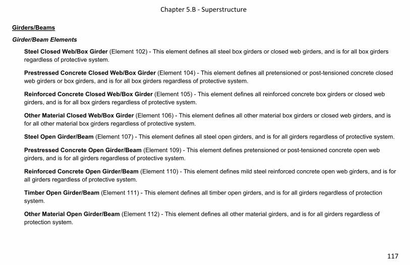
Chapter 5.B - Superstructure
117
Girders/Beams
Girder/Beam Elements
Steel Closed Web/Box Girder (Element 102) - This element defines all steel box girders or closed web girders, and is for all box girders
regardless of protective system.
Prestressed Concrete Closed Web/Box Girder (Element 104) - This element defines all pretensioned or post-tensioned concrete closed
web girders or box girders, and is for all box girders regardless of protective system.
Reinforced Concrete Closed Web/Box Girder (Element 105) - This element defines all reinforced concrete box girders or closed web
girders, and is for all box girders regardless of protective system.
Other Material Closed Web/Box Girder (Element 106) - This element defines all other material box girders or closed web girders, and is
for all other material box girders regardless of protective system.
Steel Open Girder/Beam (Element 107) - This element defines all steel open girders, and is for all girders regardless of protective system.
Prestressed Concrete Open Girder/Beam (Element 109) - This element defines pretensioned or post-tensioned concrete open web
girders, and is for all girders regardless of protective system.
Reinforced Concrete Open Girder/Beam (Element 110) - This element defines mild steel reinforced concrete open web girders, and is for
all girders regardless of protective system.
Timber Open Girder/Beam (Element 111) - This element defines all timber open girders, and is for all girders regardless of protection
system.
Other Material Open Girder/Beam (Element 112) - This element defines all other material girders, and is for all girders regardless of
protection system.

Chapter 5.B – Superstructure 118
Girder/Beam Commentary
• Girders/beams are horizontal flexural members that are the main or primary support for the deck.
• A linear structural member designed to span from one support (pier/bent/abutment) to another, and transfer loads from the deck to the
substructure.
• Girders and beams can be differentiated from one another based on configuration. Girders will typically have a built-up floor system, which
will be comprised of floor beams and stringers. Beams will not have these additional floor systems members, but may use diaphragms for
lateral stability.
• Condition evaluation for this element includes both web faces and top and bottom faces of each exposed flange.
• If the top flange of the girder/beam is cast into a concrete deck, this face will not be rated unless section loss readings are obtained via NDE
methods.
• This element does not take into account the condition of the protective coating.
Girder/Beam Quantity Calculation
• The quantity should include the sum of the lengths of every girder/beam from end to end.
• The quantity will be the size of the defect rounding up to the nearest whole foot. The height/depth of the defect per linear foot of element
does not factor into the quantity calculation, but may affect the condition state.
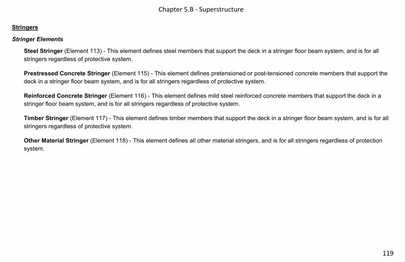
Chapter 5.B - Superstructure
119
Stringers
Stringer Elements
Steel Stringer (Element 113) - This element defines steel members that support the deck in a stringer floor beam system, and is for all
stringers regardless of protective system.
Prestressed Concrete Stringer (Element 115) - This element defines pretensioned or post-tensioned concrete members that support the
deck in a stringer floor beam system, and is for all stringers regardless of protective system.
Reinforced Concrete Stringer (Element 116) - This element defines mild steel reinforced concrete members that support the deck in a
stringer floor beam system, and is for all stringers regardless of protective system.
Timber Stringer (Element 117) - This element defines timber members that support the deck in a stringer floor beam system, and is for all
stringers regardless of protective system.
Other Material Stringer (Element 118) - This element defines all other material stringers, and is for all stringers regardless of protection
system.

Chapter 5.B – Superstructure 120
Stringer Commentary
• Condition evaluation for this element includes both web faces and top and bottom faces of each exposed flange.
• If the top flange of the stringer is cast into a concrete deck, this face will not be rated unless section loss readings are obtained via NDE
methods.
• This element does not take into account the condition of the protective coating.
• Stringers are longitudinal beams spanning between transverse floor beams and support bridge decks.
• Stringers can be continuous or simple configuration. The configuration can be noted by the placement of the stringers with respect to the
floor beams.
o Continuous stringers are placed on top of the floor beam and transfer the load of the deck into the floor beam.
o Simple span stringers can be gusseted into the side or sit on top of the floor beams and share the load of the deck with the floor
beams.
Stringer Quantity Calculation
• The quantity should include the sum of the lengths of every stringer from end to end.
• The quantity will be the size of the defect rounding up to the nearest whole foot. The height/depth of the defect per LF of element does not
factor into the quantity calculation, but may affect the condition state.

Chapter 5.B - Superstructure
121
Trusses/Arches
Truss/Arch Elements
Steel Truss (Element 120) - This element defines all steel truss elements, including all tension and compression members, and
through and deck trusses. It is for all trusses regardless of protective system.
Timber Truss (Element 135) - This element defines all timber truss elements, including all tension and compression members for
through and deck trusses. It is for all trusses regardless of protective system.
Other Material Truss (Element 136) - This element defines all other material truss elements, including all tension and compression
members, and through and deck trusses. It is for all other material trusses regardless of protective system.
Steel Arch (Element 141) - This element defines steel arches regardless of type, and is for all arches regardless of protective system.
Other Material Arch (Element 142) - This element defines other material arches regardless of type, and is for all other material arches
regardless of protective system.
Prestressed Concrete Arch (Element 143) - This element defines only pretensioned or post-tensioned concrete arches.
Reinforced Concrete Arch (Element 144) - This element defines only mild steel reinforced concrete arches, and is for all arches
regardless of protective system.
Masonry Arch (Element 145) - This element defines masonry or stacked stone arches, and is for all arches regardless of protective
system.
Timber Arch (Element 146) - This element defines only timber arches, and is for all arches regardless of protective system.

Chapter 5.B – Superstructure 122
Truss/Arch Commentary
• Trusses are jointed structures made up of individual members primarily carrying axial loads arranged and connected in triangular patterns.
• All bracing above roadway are considered part of truss, including the lateral bracing vertical sway bracing and portals. These will be coded
with the truss element. The lower lateral bracing will be coded as an assessment.
• Arches are curved structure elements primarily in compression that transfers vertical loads through inclined reactions to its end supports.
• Prior to inspection, the inspector should determine the location of each tension and compression member. More scrutiny should be used on
tension members, especially in fracture critical situations.
• Typically, trusses/arches will be separated by denoting panel points along the bridge. These are the location where members (verticals and
diagonals) meet at the bottom/top chord, starting at Panel Point 0 in line with stationing, or Agency convention. When noting defects, panel
points can be used as a reference point for specifying specific locations of defects. For filled arches, the arch quantity shall be measured
from spring line to spring line. The length below the spring line is considered substructure.
Truss/Arch Quantity Calculation
• The quantity of a truss should include the sum of all lengths of each truss panel measured longitudinal to the travel way.
• Due to the way quantities are calculated, a vertical’s Condition State will typically be quantified as 1LF, regardless of the amount of
deterioration. Supplementary notes will be required to specify specific defects in these instances.
o Example: A vertical on a truss bridge was hit by a truck and is deformed. 1LF would be moved to a higher condition state, but
additional commentary will be required to identify the defect.
• Spandrel columns will be rated with the arch, as they are considered integral with the arch.
• A filled arch shall be measured from spring line to spring line. The length below the spring line is considered substructure.
• An open arch shall be quantified by adding the sum of all of the lengths of each arch section measured longitudinally along the travelled
way.
• Observed distress in arch diagonals, vertical members (including spandrel columns) and spandrel walls shall be reported as the projected
length along the travelled way.

Chapter 5.B - Superstructure
123
Floor Beams
Floor Beam Elements
Steel Floor Beam (Element 152) - This element defines only steel elements that typically support stringers, and is for all floor beams
regardless of protective system.
Prestressed Concrete Floor Beam (Element 154) - This element defines only prestressed elements that typically support stringers,
and is for all floor beams regardless of protective system.
Reinforced Concrete Floor Beam (Element 155) - This element defines mild steel reinforced concrete floor beams that typically
support stringers, and is for all floor beams regardless of protective system.
Timber Floor Beam (Element 156) - This element defines only timber superstructure elements that typically support stringers, and is
for all floor beams regardless of protective system.
Other Material Floor Beam (Element 157) - This element defines other material floor beams that typically support stringers, and is for
all floor beams regardless of protective system.

Chapter 5.B – Superstructure 124
Floor Beam Commentary
• Floor beams are primary members located transversely to the general bridge alignment.
• Condition evaluation for this element includes both web faces and top and bottom faces of each exposed flange.
• If the top flange of the floor beam is cast into a concrete deck, this face will not be rated unless section loss readings are obtained via NDE
methods.
• This element does not take into account the condition of the protective coating.
Floor Beam Quantity Calculation
• The quantity should include the sum of the lengths of all floor beams measured from end to end.
• The quantity will be the size of the defect rounding up to the nearest whole foot. The height/depth of the defect does not factor into the
quantity calculation, but may affect the condition state.

Chapter 5.B - Superstructure
125
Miscellaneous Superstructure Elements
Miscellaneous Superstructure Elements
Steel Main Cables (Element 147) - This element defines all steel main suspension or cable stay cables not embedded in concrete. The
suspender cables in a suspension bridge are evaluated under Element 148. Cable stay systems typically include a sheath that protects
the cable bundles, which are grouted within each cable stay. It is for all cable groups regardless of protective systems.
Secondary Steel Cables (Element 148) - This element defines all steel suspender cables not embedded in concrete. It is for all
individual or cable groups regardless of protective systems.
Steel Pin and Pin & Hanger Assembly or both (Element 161) - This element defines steel pins and pin and hanger assemblies and
is for all assemblies regardless of protective system.
Steel Gusset Plate (Element 162) - This member defines only those steel gusset plate(s) connections that are on the main truss/arch
panel(s). These connections can be constructed with one or more plates that may be bolted, riveted, or welded. Both sides of a chord
are equal to one gusset plate. Gusset plates within a bracing system (i.e. lateral bracing gusset plates) should not be evaluated here.
This element is for all gusset plates regardless of protective systems.
Steel Tension Rods/ Post-Tensioned Cables (Element 8165) - Defines rods and/or post tensioned cables that are visible to be
inspected. Tensioning rods will typically be located within a member and will not be accessible to the inspector unless the member
was post-tensioned during construction.
Other Primary Structural Members (Element 8170) - Defines other structural members not defined by previous elements. Differing
types of structural bracing that don’t fall into any other category could be used for this element as an example.

Chapter 5.B – Superstructure 126
Miscellaneous Superstructure Commentary
• None
Miscellaneous Superstructure Quantity Calculation
• The quantity should include the sum of the length (LF) of the main cables and total number (EA) of secondary cables.
• Element 161
o Individual pins that link girders to a transverse girder will be counted individually.
o Pin and hanger assemblies will be counted as each assembly (two pins and two hanger bars equal one assembly)
• Element 162 – Gusset Plate: Gusset plates will be measured as one per panel point, regardless of the number of plates used to comprise
the connection.

Chapter 3.C - Substructure
127
C. Substructure
• Typically the substructure includes all elements below the bearings.
• Substructure units function as both axially-loaded and bending members. These units resist both vertical and horizontal loads applied
from the superstructure and roadway embankment.
• Element 207 – Steel Tower and Element 208 – Timber Trestle are quantified by the sum of the vertical heights of each tower/trestle per
linear foot.
• Substructure elements are either quantified as each for piles and columns or linear feet as with piers, caps, abutments and culverts.
When quantifying culverts, measure the distance along the length of the culvert (pipe, barrel or cell) and sum all of the lengths of pipes,
barrels or cells to establish the total quantity.
• In addition to assessing the elements per the material defects specific to the substructure element, consideration should be given to the
effects of scour, undermining and settlement on the various elements.
• Scour is the removal of material from the streambed or embankment as a result of the erosive action of stream flow. It is important for
the inspector to recognize that there are four types of scour that can affect a bridge and channel. These are:
o General scour – occurs whether there is a bridge crossing or not. It includes natural streambed movements and natural river
lateral movements over time.
o Contraction scour – caused by an increase in water flow velocity as a result of channel constriction. Building a bridge over a
waterway will often cause this. Contraction scour will cause a lowering of the streambed across the entire channel width.
o Local scour – occurs around an obstruction within the waterway, such as a bridge pier or abutment. The obstructions cause
water turbulence, which stirs up the streambed material and allows it to be removed. Local scour is more severe when
substructures do not line up with the flow of the stream or when blunt shapes (squared off pier ends) are used instead of
streamlined shapes (round or tapered pier ends).
o Lateral bank scour – caused by stream meandering, channel widening or man-made channel changes. It affects abutments,
wingwalls, and approach embankments.
Chapter 5.C – Substructure 128
THIS PAGE IS INTENTIONALLY LEFT BLANK

Chapter 5.C - Substructure
129
Columns/Pier Walls
Column/Pier Wall Elements
Steel Column (Element 202) - This element is for all steel columns regardless of protective system.
Other Material Column (Element 203) - This element is for all other material columns regardless of protective system.
Prestressed Concrete Column (Element 204) - This element is for all prestressed concrete columns regardless of protective system.
Reinforced Concrete Column (Element 205) - This element is for all reinforced concrete columns regardless of protective system.
Timber Column (Element 206) - This element is for all timber columns regardless of protective system.
Steel Tower (Element 207) - This element defines steel built up or framed tower supports, and is for all towers regardless of protective
system.
Timber Trestle (Element 208) - This element defines framed timber supports, and is for all timber trestles regardless of protective
system.
Reinforced Concrete Pier Wall (Element 210) - This element defines reinforced concrete pier walls, and is for all pier walls
regardless of protective systems.
Other Material Pier Wall (Element 211) - This element defines those pier walls constructed of other materials. This is for all pier walls
regardless of protective systems.
Timber Pier Wall (Element 212) - This element defines those timber pier walls that include pile, timber sheet material, and filler. This
is for all pier walls regardless of protective systems.
Masonry Pier Wall (Element 213) - This element defines those pier walls constructed of block or stone. The block or stone may be
placed with or without mortar. This is for all pier walls regardless of protective systems.

Chapter 5.C – Substructure 130
Column/Pier Wall Commentary
• Columns are vertical members which can carry axial load, horizontal load, and bending and are used as substructure elements.
• Columns may be supported on footings or they may be constructed as drilled shafts.
• Column/Pier footings can be either spread footings or pile supported footings.
• Pier walls transmit the load from the pier cap to the footing
Column/Pier Wall Quantity Calculation
• The columns quantity should include the total number of Columns.
• The pier wall quantity should include the sum of the horizontal lengths measured along the skew angles.
• Steel towers and timber trestles will be quantified by the sum of the vertical heights of each tower/trestle per linear foot.

Chapter 5.C - Substructure
131
Abutments/End Bents
Abutment/End Bent Elements
Reinforced Concrete Abutment (Element 215) - This element defines reinforced concrete abutments. This includes the material
retaining the embankment and monolithic wingwalls and abutment extensions. This is for all reinforced concrete abutments regardless
of protective systems.
Timber Abutment (Element 216) - This element defines timber abutments. This includes the sheet material retaining the
embankment, integral wingwalls and abutment extensions. This is for all abutments regardless of protective systems.
Masonry Abutment (Element 217) - This element defines those abutments constructed of block or stone, including integral wingwalls
and abutment extensions. The block or stone may be placed with or without mortar. This is for all abutments regardless of protective
systems.
Other Material Abutments (Element 218) - This element defines other material abutment systems. This includes the sheet material
retaining the embankment, and integral wingwalls and abutment extensions. This is for all abutments regardless of protective systems.
Steel Abutment (Element 219) - This element defines steel abutments. This includes the sheet material retaining the embankment,
and monolithic wingwalls and abutment extensions. This is for all abutments regardless of protective systems.
Integral Wingwall (Element 8400) - This element defines the wingwalls integral with the abutment which extend past the bridge seat for parallel wingwalls, or at the skew point when the wingwalls are turned back.

Chapter 5.C – Substructure 132
Abutment/End Bent Commentary
• Abutments are at either end of the bridge and transfer loads from the superstructure to foundation and provides lateral support for the
roadway approach embankment.
• Integral wingwalls will include all monolithic sections of the wingwall whether parallel to the abutment past the bridge seat, or from the skew
point when the wingwalls are turned back.
• Wingwalls that are not monolithic with the abutment or past the skewed wingwall stub will be considered retaining walls.
Abutment/End Bent Quantity Calculation
• The quantity should include the sum of the width of the abutments only from edge of bridge seat to edge of bridge seat, or from skew angle
to skew angle.
• End Bents are pile supported caps, which support the bearings and superstructure. The end bent cap is quantified in linear feet while the
piles are quantified as the number of piles. Only the piles that are visible are quantified. The material that is retaining the embankment
material on an end bent is what determines the abutment material type.
• Each integral wingwall inspected will be quantified as one Each.

Chapter 5.C - Substructure
133
Piles/Caps/Footings
Pile/Cap/Footing Elements
Reinforced Concrete Pile Cap/Footing (Element 220) - This element defines reinforced concrete pile caps/footings that are visible for
inspection. Pile caps/footings exposed from erosion or scour or visible during an underwater inspection are included in this element.
The exposure may be intentional or caused by erosion or scour.
Steel Pile (Element 225) - This element defines steel piles that are visible for inspection
Prestressed Concrete Pile (Element 226) - This element defines prestressed concrete piles that are visible for inspection
Reinforced Concrete Pile (Element 227) - This element defines reinforced concrete piles that are visible for inspection.
Timber Pile (Element 228) - This element defines timber piles that are visible for inspection.
Other Material Pile (Element 229) - This element defines other material piles that are visible for inspection.
Steel Pier Cap (Element 231) - This element defines those steel pier caps that support girders and transfer load into piles or columns.
Prestressed Concrete Pier Cap (Element 233) - This element defines those prestressed concrete pier caps that support girders and
transfer load into piles or columns.
Reinforced Concrete Pier Cap (Element 234) - This element defines those reinforced concrete pier caps that support girders and
transfer load into piles or columns.
Timber Pier Cap (Element 235) - This element defines those timber pier caps that support girders that transfer load into piles or
columns.
Other Material Pier Cap (Element 236) - This element defines other material pier caps that support girders that transfer load into piles
or columns.

Chapter 5.C – Substructure 134
Pile/Cap/Footing Commentary
• Piles are typically precast concrete, timber or steel and are part of a pile bent. A pile bent consists of the pile cap and piles. Piles in a pile
bent are not supported by footings.
• Footings are the enlarged, lower portion of a substructure, which distributes the structure load either to the earth through a spread footing or
to supporting piles or drilled shafts.
• If an element is visible, it must be quantified accordingly.
• If the inspector finds a footing or portion of footing exposed, they must determine if the footing is a spread footing or pile supported. An
exposed spread footing is a much more serious condition and must be addressed immediately. The element must also be coded.
• Piles exposed from erosion or scour, and piles visible during an underwater inspection are included in all pile elements. Only those exposed
are to be assessed and quantified.
• All piles and caps should be inspected as the material they are regardless of protection system.
• Cast in Place (CIP) piles with steel shells will be coded under the steel element. If deterioration of the steel shell is noted, the inspector
must determine if the concrete inside of the shell is reinforced or not. This will assist of the severity of the shell corrosion (whether or not the
steel shell is sacrificial or not.
Pile/Cap/Footing Quantity Calculation
• The quantity for pier caps and pile caps/ footings is the sum of the cap lengths measured along the skew angle.
• The quantity for piles is the sum of the number of piles visible for inspection.
• Non-visible piles are not quantified.
Chapter 5.C - Substructure
135
Culverts
Culvert Elements
Steel Culvert (Element 240) - This element defines steel culverts, including arched, round, or elliptical pipes.
Reinforced Concrete Culvert (Element 241) - This element defines reinforced concrete culverts, including box, arched, round, or
elliptical shapes.
Timber Culvert (Element 242) - This element defines all timber culverts.
Other Material Culvert (Element 243) - This element defines other material type culverts, including arches, round, or elliptical pipes.
These culverts are not included in steel, concrete, or timber material types.
Masonry Culvert (Element 244) - This element defines masonry block or stone culverts.
Prestressed Concrete Culvert (Element 245) - This element defines all prestressed concrete culverts.

Chapter 5.C – Substructure 136
Culvert Commentary
• A culvert is primarily a hydraulic structure, must have a floor, and its main purpose is to transport water flow efficiently.
• Rigid culvert’s load carrying capacity is primarily provided by the structural strength of the culvert, with little strength developed from the
surrounding soil. Rigid culverts typically do not bend or deflect appreciably when loaded
• Flexible culverts have little structural bending strength without proper backfill. Flexible culverts depend on the backfill for support to resist
bending and as a result proper interaction between the soil and structure is critical.
• The distortion defect is contingent on a number of factors such as site, wall thickness, fill depth, etc. The inspector shall use such factors to
assess the proper condition state.
• Culverts are defined as structures that have a floor.
Culvert Quantity Calculation
• The quantity should include the flow line length of the barrel multiplied by the number of barrels, excluding the aprons and end treatments.
• A culvert longer than 20 feet measured along the centerline of the roadway is considered a bridge for NBI reporting purposes.
Chapter 5.D - Bearings
137
D. Bearings
Bearing Elements
Elastomeric Bearing (Element 310) - This element defines only those bridge bearings that are constructed primarily of elastomers,
with or without fabric or metal reinforcement.
Movable Bearing (Element 311) - This element defines only those bridge bearings which provide for both rotation and longitudinal
movement by means of roller, rocker, or sliding mechanisms.
Fixed Bearing (Element 313) - This element defines only those bridge bearings that provide for rotation only (no longitudinal
movement).
Pot Bearing (Element 314) - This element defines those high load bearings with confined elastomer. The bearing may be fixed against
horizontal movement, guided to allow sliding in one direction, or floating to allow sliding in any direction.
Disc Bearing (Element 315) - This element defines those high load bearings with a hard plastic disk. This bearing may be fixed
against horizontal movement, guided to allow movement in one direction, or floating to allow sliding in any direction.
Other Bearing (Element 316) - This element defines all other material bridge bearings regardless of translation or rotation constraints.
Bearing Commentary
• A bridge bearing is an element which provides an interface between the superstructure and substructure.
• Bridge bearings transmit all primary live loads from superstructure to substructure, permit longitudinal movement of the superstructure due
to thermal expansion and contraction, and allow rotation due to dead and live load deflection.
Bearing Quantity Calculation
• The quantity should include the number of each type of bearing.

Chapter 5.D – Bearings 138
THIS PAGE IS INTENTIONALLY LEFT BLANK

Chapter 5.E – Bridge Railing
139
E. Bridge Rail
Bridge Rail Elements
Metal Bridge Railing (Element 330) - This element defines all types and shapes of metal bridge railing. Steel, aluminum, metal beam,
rolled shapes, etc. will all be considered part of this element. Included in this element are the posts of metal, timber or concrete,
blocking, and curb.
Reinforced Concrete Bridge Railing (Element 331) - This element defines all types and shapes of reinforced concrete bridge railing.
All elements of the railing must be concrete.
Timber Bridge Railing (Element 332) - This element defines all types and shapes of timber bridge railing. Included in this element are
the posts of timber, metal or concrete, blocking, and curb.
Other Material Bridge Railing (Element 333) - This element defines all types and shapes of bridge railing except those defined as
metal, concrete, timber, or masonry.
Masonry Bridge Railing (Element 334) - This element defines all types and shapes of masonry block or stone bridge railing. All
elements of the railing must be masonry block or stone.

Chapter 5.E – Bridge Railing 140
Bridge Rail Commentary
• The function of bridge railing is to contain and smoothly redirect errant vehicles on the bridge.
• The number of rows of rail on a bridge is commonly two, one on each side of the traveled way. In some cases there may be more than two
rows when the bridge has a center median, or protected pedestrian/bicycle lanes. Refer to the other bridge rail material elements (concrete,
timber, masonry, other) for specific defects for assessing the condition of posts, blocking and curbs that may be constructed of materials
other than metal.
• Concrete bridge railing will be defined as concrete and masonry > 12”. If the railing is < 12”, then it will be considered curb.
• All railings on top of concrete and masonry bridge railing will be considered an assessment.
• In some instances, a bridge rail may be made up of more than one material (i.e., steel pedestrian rail mounted on a concrete barrier). The
most predominant crash approved material should be rated in these instances.
• Curb along the length of the railing will be coded as part of the railing and not with the deck.
Bridge Rail Quantity Calculation
• The quantity should include the number of barriers or railings times the length of the bridge, including any rails on integral wingwalls.
• Railings are measured along the edge from wingtip to wingtip of integral wingwalls.

Chapter 6 – Bridge Management Elements/Agency Defined Elements
141
Bridge Management Elements/Agency Defined Elements Chapter 6.
• This section describes structure elements that agencies collect to support their Bridge Management System (BMS).
• Agency Defined Elements (ADE) described in this section will be defined as an 8000 series number.

Chapter 6.A – Joints 142
A. Joints
Joint Elements
Strip Seal Expansion Joint (Element 300) - This element defines those expansion joint devices which utilize a neoprene type
waterproof gland with some type of metal extrusion or other system to anchor the gland.
Pourable Joint Seal (Element 301) - This element defines those joints filled with a pourable seal with or without a backer.
Compression Joint Seal (Element 302) - This element defines only those joints filled with a preformed compression type seal. This
joint may or may not have an anchor system to confine the seal.
Modular Joint (Element 303) - This element defines only those joints filled with an assembly mechanism that has a seal.
Open Expansion Joint (Element 304) - This element defines only those joints that are open and not sealed.
Assembly Joint without Seal (Element 305) - This element defines only those assembly joints that are open and not sealed. This
includes finger and sliding plate joints.
Other Joint (Element 306) - This element defines only those other joints that are not defined by any other joint element.

Chapter 6.B – Structural Approach Slabs
143
B. Structural Approach Slabs
Structural Approach Slab Elements
Prestressed Concrete Structural Approach Slab (Element 320) - This element defines those structural sections, between the
abutment and the approach pavement that are constructed of prestressed reinforced concrete.
Reinforced Concrete Structural Approach Slab (Element 321) - This element defines those structural sections, between the
abutment and the approach pavement, that are constructed of mild steel reinforced concrete.
Structural Approach Slab Commentary
• Structural concrete approach slab surfaces that are not visible for inspection shall be assessed based on the available visible surface.
• If both top and bottom surfaces are not visible, the condition shall be assessed based on destructive and nondestructive testing or indicators
in the materials covering the surfaces.
• Both Elements 320 and 321 are for structural approach slabs only. Non-structural approach slabs will be coded under the applicable
Assessment.
• Structural approach slabs will have one end resting on the abutment paving notch, and the other end resting on a grade beam.
Structural Approach Slab Quantity Calculation
• The quantity should include the area of the slab from the adjacent bridge deck joint to the leading roadway, and from edge to edge including
any median areas, flares, or ramps present.

Chapter 6.C – Protective/Strengthening Systems 144
C. Protective/Strengthening Systems
Protective/Strengthening System Elements
Steel Protective Coating (Element 515) - The element is for steel elements that have other protective coatings not listed below.
Painted Steel (Element 8516) - Paint systems applied to superstructure or substructure primary structural members.
Weathering Steel (Element 8517) - Protective system for steel.
Galvanization (Element 8518) - Galvanized protective systems.
Duplex Systems (Element 8519) – Protective system comprised of paint coating over galvanized coating.
Concrete Reinforcing Steel Protective System (Element 520) - This element defines other types of protective systems used to
protect reinforcing steel in concrete elements from corrosion not listed below.
Coated Reinforcing (Element 8522) - Defines all types of coating systems (epoxy, galvanized, Zbar, etc.) over reinforcing steel.
Place note in comments for element if the deck/slab has top mat only protection.
Stainless Steel Reinforcing (Element 8523) - Stainless steel reinforcement used in deck mats.
Non-Metallic Reinforcing (Element 8524) - Defines non-metallic systems (FRP, GFRP, etc.).
Concrete Protective Coating (Element 521) - This element is for concrete elements that have a protective coating applied to them.
These coatings include silane/siloxane water proofers, crack sealers such as High Molecular Weight Methacrylate (HMWM), or any top
coat barrier that protects concrete from deterioration and reinforcing steel from corrosion.

Chapter 6. C – Protective/Strengthening Systems
145
FRP (Element 8800) - This defines FRP wrapped columns and pier caps as well as FRP used for strengthening slabs and beams.
Jacketing (Element 8801) - This defines jackets placed around columns, piles, etc.
Culvert Liner (Element 8802) - This defines culverts with liners inserted for structural stability/strengthening.
External Post Tensioning (Element 8803) - This element defines the system used to strengthen structural member, such as a beam,
column, cap, or footing by means of external post tensioning.

Chapter 6.D – Wearing Surfaces 146
D. Wearing Surfaces
Wearing Surface Elements
Wearing Surfaces (Other) (Element 510) - This element is for all decks/slabs that have overlays other than those listed below, such
as timber running planks.
Wearing Surface (Bare) (Element 8000) - This element defines decks/slabs that do not have a wearing surface and will be coded to
capture the top of a deck/slab without a wearing surface.
AC Overlay (Element 8511) – Defines flexible asphaltic overlay.
AC Overlay & Membrane (Element 8512) - Defines flexible asphalt overlays with membranes or PMA systems.
Thin Polymer Overlay (Element 8513) - Defines thin polymer overlays.
Concrete Overlay (Element 8514) - Defines rigid concrete overlays.
Polyester Concrete Overlay (Element 8515) - Defines polyester concrete overlay systems.

Chapter 6. E – Wall Elements
147
E. Wall Elements
Earth Retention Elements
CIP Concrete Wall (Element 8600) - Cast-in-place (CIP) concrete walls are made by placing ready-mix concrete into removable forms
that are built around reinforcing steel at the final intended position of the wall. A concrete wall will have to be anchored and can
incorporate tie-backs or prestressed soil anchors for stabilization depending on the height of the wall and characteristics of the soil that
is being restrained.
Gabion Wall (Element 8601) - Gabion walls are constructed from rock-filled wire mesh baskets. The gabions typically have a heavy
wire mesh with a nominal 3-inch opening and are formed into rectangular baskets, normally 1.5 to 3 feet in height.
Gravity (Block & Rubble) Wall (Element 8602) - A gravity wall is a large monolithic structure, which depends entirely on its self-
weight and the weight of the soil that rests upon it for stability. The walls are typically constructed of concrete or masonry with very
little, if any, steel reinforcement. Concrete gravity walls are typically less than 10 feet tall, and segmented modular block gravity walls
are limited by design to an exposed height of 4’-0”.
MSE Wall (Element 8603) - A mechanically stabilized earth (MSE) wall is based on the principle of integrating reinforcing into a
granular backfill via means such as metal strips or rods, geosynthetic sheets, or wire grids. The reinforcing is tied to precast concrete
facing units, which form the vertical face of the wall. The facing units are relatively small and piece together in a geometric pattern. The
reinforcing is attached at regular intervals throughout the width and height of the wall.
MSE Walls can be constructed with different materials including precast concrete panel facings (classic vertical faced MSE walls),
Modular Block facings (battered segmental retaining walls), and Wire faced walls. The Segmented Modular Block Retaining Wall is
the most common of MSE structure in Wisconsin. Although these walls can act as Gravity walls, they are often constructed as MSE
walls.
Post & Panel Wall (Element 8604) - Post and Panel Walls are comprised of vertical elements (usually H piles) and concrete panels
which extend between the vertical elements. The panels resist lateral soil pressures by spanning horizontally between the posts. The
panels are usually constructed of precast reinforced concrete although precast/prestressed concrete and timber are also possibilities
Chapter 6.E – Wall Elements 148
Sheet Pile Wall (Element 8605) - Sheet pile walls are most often temporary, but may be permanent structures as well. The corrosion
potential for these walls is high, and site conditions should be taken into account. A steel sheet pile wall can be a maximum of
approximately 15 feet high without tiebacks being required.
Reinforced Soil Slope (Element 8606) - Reinforced soil slops add tensile inclusions with soil to create a composite material. The
tensile inclusions are typically geosynthetic reinforcement. Vegetation can be used as the facing of the composite material for slopes
less than 45 degrees but more significant armoring may be needed for steeper slopes such as concrete.
Secant or Tangent Shaft Wall (Element 8607) - Secant and Tangent walls are a series of interlocking concrete shafts. Secant shaft
walls have primary shafts that are poured first and then secondary shafts are poured that interlock the primary shafts. The tangent
shall walls are constructed similarly except that the secondary shafts only touch the primary shafts without any of the interlocking
properties.
Other Wall and Other Material Wall (Element 8608) - This element is intended to be used for any type of earth retention wall that
does not fit into any of the previously mentioned elements.
Noise Barrier Elements
Noise Barrier/Wall (Element 8609) - A noise barrier is a constructed appurtenance, either alone or integrated with other systems that
alter the normal noise travel at a site.

Chapter 7 – Emergency Notification
149
Emergency NotificationChapter 7.

Chapter 8 – NBI Rating System 150
NBI Rating System Chapter 8.
NBI Deck, Superstructure, Substructure Rating System
The following criteria should be used to rate items 58 (Deck), 59 (Superstructure), and 60 (Substructure).
NBI Description
N NA Not Applicable
9
Good
Excellent condition
8 Very good condition – no problems noted
7 Good condition – some minor problems
6
Fair
Satisfactory condition – structural elements show some minor deterioration
5 Fair condition – all primary structural elements are sound, but may have minor section loss, cracking, spalling, or scour
4
Poor
Poor condition – advanced section loss, deterioration, spalling, or scour
3 Serious condition – loss of section, deterioration, spalling, or scour have seriously affected primary structural components. Local failures are possible. Fatigue cracks in steel or shear cracks in concrete may be present.
2
Severe
Critical condition – advanced deterioration of primary structural elements. Fatigue cracks in steel or shear cracks in concrete may be present or scour may have removed substructure support. Unless closely monitored it may be necessary to close the bridge until corrective action is taken.
1 “Imminent” failure condition – major deterioration or section loss in critical structural components or obvious vertical or horizontal movement affecting structure ability. Bridge is closed to traffic but with corrective action may put back in light service.
0 Failed condition – out of service – beyond corrective action

Chapter 8 – NBI Rating System
151
Quick Assessment Chart for NBI Deck Rating vs. Defect Comparison
DECK
RATING CRACKING SCALING SPALLING DELAM.
ELECTRICAL
POTENTIAL
CHLORIDE
CONTENT (LB/CY)
9 None None None None 0 0
8 Minor Transverse None None None None > 0.35 None > 2.0
7 Sealable Light None but Visible
Tire Wear None 10% > 0.35 10% > 2.0
6 Excessive (open cracks @
5 foot Max. Spa.) Medium < 2% < 5% 10% -20% > 0.35 10%-20% > 2.0
5 Excessive Heavy 2% - 5% 5% - 20% 20%-40% > 0.35 20%-40% > 2.0
4 Many Full Depth Failures Present or imminent; leaching > 20% Over 60% > 0.35 Over 60% > 2.0
3 Many Full Depth Failures Present or imminent; leaching
2 Full Depth Failures over Much of Deck
1 Bridge Closed. Corrective Action May Put Back in Service
0 Bridge Closed. Replacement necessary

Chapter 8 – NBI Rating System 152
NBI Culvert Ratings
These criteria should be used to rate item 62 (Culvert). Further detail on culvert rating can be found in the Wisconsin Inspection Structure
Manual.
NBI Description
N NA Not Applicable
9
Good
No deficiencies
8 No noticeable or noteworthy deficiencies which affect the condition of the culvert. Insignificant scrape marks caused by drift.
7 Shrinkage cracks, light scaling, and insignificant spalling which does not expose reinforcing steel. Insignificant damage caused by drift with no misalignment and not requiring corrective action. Some minor scouring has occurred near curtain walls, wingwalls, or pipes. Metal culverts have smooth symmetrical curvature with superficial corrosion and not pitting.
6
Fair
Deterioration or initial disintegration, minor chloride contamination, cracking with some leaching, or spalls on concrete or masonry walls and slabs. Local minor scouring at curtain walls, wingwalls, or pipes. Metal culverts have smooth curvature, non-symmetrical shape, significant corrosion and moderate pitting.
5 Moderate to major deterioration or disintegration, extensive cracking and leaching, or spalls on concrete or masonry walls and slabs. Minor settlement or misalignment. Noticeable scouring or erosion at curtain walls, wingwalls or pipes. Metal culverts have significant corrosion or deep pitting.
4
Poor
Large spalls, heavy scaling, wide cracks, considerable efflorescence, or opened construction joint permitting loss of backfill. Considerable settlement or misalignment. Considerable scouring or erosion at curtain walls, wingwalls, or pipes. Metal culverts have significant distortion and deflection throughout, extensive corrosion or deep pitting.
3
Any condition which is described in Code 4 but which is excessive in scope. Severe movement or differential settlement of the segments, or loss of fill. Holes may exist in walls or slabs. Integral wingwalls nearly severed from culvert. Severe scour or erosion at curtain walls, wingwalls, or pipes. Metal culverts have extreme distortion and deflection in one section, extensive corrosion, or deep pitting with scattered perforations.
2
Severe
Integral wingwalls collapsed, severe settlement of roadway due to loss of fill. Section of Culvert may have failed and can no longer support embankment. Complete undermining at curtain walls and pipes. Corrective action required to maintain traffic. Metal culverts have extreme distortion and deflection throughout with extensive perforations due to corrosion.
1 Bridge closed. Corrective action may put back in light service.
0 Bridge closed. Replacement necessary

Chapter 8 – NBI Rating System
153
NBI Channel and Channel Protection
This item describes the physical conditions associated with the flow of water through the bridge such as stream stability and condition of the
channel, riprap, slope protection, or stream control devices including spur dikes. The following codes should be used as a guide in evaluating
the condition of the channel and channel protection. Further detail on channel condition rating can be found in the WisDOT Structure Inspection
Manual.
NBI Description
N NA Not applicable. Use when bridge is not over waterway.
9
Good
There are no noticeable or noteworthy deficiencies which affect the condition of the channel.
8 Banks protected or well vegetated. River control devices (spur dikes, embankment protection are not required or in stable condition).
7 Bank protection is in need of minor repairs. River control devices such as spur dikes and embankment protection have a little minor damage. Banks and/or channel have minor amounts of drift.
6
Fair
Bank is beginning to slump. River control devices and embankment protection have widespread minor damage. There is minor streambed movement evident. Debris is restricting the waterway slightly.
5 Bank protection is being eroded. River control devices and/or embankment have major damage. Trees and brush restrict the channel.
4
Poor
Bank and embankment protection is severely undermined. River control devices have severe damage. Large deposits of debris are in the waterway.
3 Bank protection has failed. River control devices have been destroyed. Streambed aggregation, degradation or lateral movement has changed the waterway to now threaten the bridge and/or approach roadway.
2
Severe
The waterway has changed to the extent the bridge is near a state of collapse.
1 Bridge is closed because of channel failure. Corrective may put back in light service.
0 Bridge is closed because of channel failure. Replacement necessary.

Chapter 8 – NBI Rating System 154
NBI Waterway Adequacy
Waterway adequacy is an appraisal of the existing bridge opening to handle the water flowing through the given opening. Rate the frequency of
overtopping the bridge and/or the approach roadway. The following coding should be used as a guide in appraising this item.
Functional Classifications
Principal Arterials, Interstates, Freeways, or Expressways
Other Principal and Minor Arterials and Major Collectors
Minor Collectors, Locals
Code Description
N N N Bridge is not over waterway.
9 9 9 Bridge deck and roadway approaches above floodwater elevations (high water). Chance of overtopping is remote.
8 8 8 Bridge deck above roadway approaches. Slight chance of overtopping bridge deck.
4 5 6 Bridge deck above roadway approaches. Occasional overtopping of roadway approaches with insignificant traffic delays.
3 4 5 Bridge deck above roadway approaches. Occasional overtopping of roadway approaches with significant traffic delays.
2 3 4 Occasional overtopping of bridge deck and roadway approaches with significant traffic delays.
2 2 3 Frequent overtopping of bridge deck and roadway approaches with significant traffic delays.
2 2 2 Occasional or frequent overtopping of bridge deck and roadway approaches with severe traffic delays.
0 0 0 Bridge Closed.

Chapter 8 – NBI Rating System
155
NBI Approach Roadway Alignment
Code the rating based on the adequacy of the approach roadway alignment. This item identifies those bridges which do not function properly or
adequately due to the alignment of the approaches. It is not intended that the approach roadway alignment be compared to current standards
but rather to the existing highway alignment. This concept differs from other appraisal evaluations. The establishment of set criteria to be used
at all bridge sites is not appropriate for this item. The basic criteria are how the alignment of the roadway approaches to the bridge relate to the
general highway alignment for the section of highway the bridge is on.
The approach roadway alignment will be rated intolerable (a code of 3) only if the horizontal or vertical curvature requires a substantial reduction
in the vehicle operating speed from that on the highway section. A very minor speed reduction will be rated a 6, and when a speed reduction is
not required, the appraisal code will be an 8.
For example, if the highway section requires a substantial speed reduction due to vertical or horizontal alignment, and the roadway approach to
the bridge requires only a very minor additional speed reduction at the bridge, the appropriate code would be a 6. This concept shall be used at
each bridge site.
Speed reductions necessary because of structure width and not alignment shall not be considered in evaluating this item.
(72) Approach Roadway Alignment Appraisal
NBI Rating Description
8 Good – No speed reduction required
6 Fair – Horizontal or Vertical curvature requires a very minor speed reduction
3 Intolerable – Horizontal or Vertical curvature requires a substantial reduction in vehicle operating speed
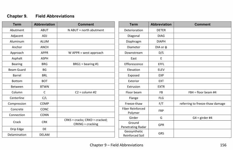
Chapter 9 – Field Abbreviations 156
Field AbbreviationsChapter 9.
Term Abbreviation Comment
Abutment ABUT N ABUT = north abutment
Adjacent ADJ
Aluminum ALUM
Anchor ANCH
Approach APPR W APPR = west approach
Asphalt ASPH
Bearing BRG BRG1 = bearing #1
Beam Guard BG
Barrel BRL
Bottom BOT
Between BTWN
Column C C2 = column #2
Centerline C/L
Compression COMP
Concrete CONC
Connection CONN
Crack CRK CRKS = cracks; CRKD = cracked;
CRKNG = cracking
Drip Edge DE
Delamination DELAM
Term Abbreviation Comment
Deterioration DETER
Diagonal DIAG
Diaphragm DIAPH
Diameter DIA or ɸ
Downstream D/S
East E
Efflorescence EFFL
Elevation ELEV
Exposed EXP
Exterior EXT
Extrusion EXTR
Floor beam FB FB4 = floor beam #4
Flange FLG
Freeze-thaw F/T referring to freeze-thaw damage
Fiber Reinforced
Polymer FRP
Girder G G4 = girder #4
Ground
Penetrating Radar GPR
Geosynthetic
Reinforced Soil GRS

Chapter 9 – Field Abbreviations
157
Term Abbreviation Comment
Hairline H/L H/L CRK = hairline crack
Horizontal HOR
Heavy HVY
Interior INT
Infrared scan IR
Joint JT
Loss of Section LOS
Mechanically
Stabilized Earth MSE
North N
Northeast NE
Northwest NW
Pier P P2 = pier #2
Pre-stress P/S
Post tension P/T
Pier cap PC
Plate PL
Panel point PP
Parapet PPT
Pack rust PR
Polymer Modified
Asphalt PMA
Term Abbreviation Comment
Quadrant QUAD
South S
Southeast SE
Shoulder SHLDR
Spall SPL
Span SP SP3 = span #3
Stringer ST ST1 = stringer #1
Stiffener STIFF
Southwest SW
Top T
Transverse TRANS
Typical TYP
Upstream U/S
Vertical VERT
Waterline W/L
West W
With W/