fife cdp-01 reference manual 1-721
TRANSCRIPT

CDP-01Reference Manual
05-25-07 CDP-01 1-721-B

THIS PAGE INTENTIONALY LEFT BLANK 1-721-B CDP-01 05-25-07

NOTE
This Operating Manual will help you to familiarize yourself with the Fife product CDP-01 and to make thefullest and most economical use of its possible applications.
Existing national regulations relating to safety and environmental protection should be observed in additionto the Operating Manual.
The legally binding safety regulations in the country of use and at the specific location apply. Please alsofollow the recognized technical rules with regard to safety and proper working practices.
The Operating Manual must be kept at hand at all times at the location where the machine is installed.
Customer-specific configurations of the CDP-01, together with further technical data, are described in aseparate section in the supplementary documentation. They have priority over the information given in thisgeneral description.
The Operating Manual must be read and applied by all persons entrusted with working on or with the ma-chine, e.g.: operation, maintenance (servicing, inspection, repair) and transportation.
Copyright:
All rights reserved. Any reproduction of this Operating Manual, in what ever form, in whole or in part, re-quires the prior written consent of FIFE.
The information given in this Operating Manual is subject to change without notice.
We have compiled this Operating Manual with the greatest possible care and attention; however, the possi-bility of error can not be completely excluded. FIFE accepts no legal liability for incorrect information givenand the consequences arising therefrom.
Copyright © 2007 FIFE GmbH, Kelkheim
FIFE U.S.A. - P.O. Box 26508 - Oklahoma City, OK. 73126, U.S.A. -Tel.: (405) 755-1600 - Fax.: (405) 755-8425 - Telex: 747276
FIFE GmbH - D 65779 Kelkheim - Fifestraße 1 - Tel.: 06195 7002-0 - Fax.: 3018
05-25-07 CDP-01 1-721-B

TABLE OF CONTENTS
GENERAL 1About the CDP-01 . . . . . . . . . . . . . . . . . . . . . . . . . . . . . . . . . . . . . . . . . . . . . . . 1-1Transport and Storage . . . . . . . . . . . . . . . . . . . . . . . . . . . . . . . . . . . . . . . . . . . . 1-1Product Package . . . . . . . . . . . . . . . . . . . . . . . . . . . . . . . . . . . . . . . . . . . . . . . 1-1
SAFETY MEASURES 2Mechanical Safety . . . . . . . . . . . . . . . . . . . . . . . . . . . . . . . . . . . . . . . . . . . . . . . 2-1Electrical Safety . . . . . . . . . . . . . . . . . . . . . . . . . . . . . . . . . . . . . . . . . . . . . . . 2-1
INSTALLATION 3Installation Location . . . . . . . . . . . . . . . . . . . . . . . . . . . . . . . . . . . . . . . . . . . . . . . 3-1Installation . . . . . . . . . . . . . . . . . . . . . . . . . . . . . . . . . . . . . . . . . . . . . . . 3-1
Mechanical AttachmentElectrical Connections
Connecting Sensors/Actuators. . . . . . . . . . . . . . . . . . . . . . . . . . . . . . . . . . . . . . . 3-2
STARTUP 41. Checking Plug-in Connections . . . . . . . . . . . . . . . . . . . . . . . . . . . . . . . . . . . . . 4-12. Calibrating the Sensor . . . . . . . . . . . . . . . . . . . . . . . . . . . . . . . . . . . . . . . . . . . 4-13. Automatic Calibration . . . . . . . . . . . . . . . . . . . . . . . . . . . . . . . . . . . . . . . . . . . . 4-2
USING THE OPERATING INSTRUCTIONS 5
CONTROL PANEL DESCRIPTION 6Operating Modes . . . . . . . . . . . . . . . . . . . . . . . . . . . . . . . . . . . . . . . . . . . . . . . 6-1Function Keys . . . . . . . . . . . . . . . . . . . . . . . . . . . . . . . . . . . . . . . . . . . . . . . 6-1Sensor Key . . . . . . . . . . . . . . . . . . . . . . . . . . . . . . . . . . . . . . . . . . . . . . . 6-2Setup Key . . . . . . . . . . . . . . . . . . . . . . . . . . . . . . . . . . . . . . . . . . . . . . . 6-2Special Keys . . . . . . . . . . . . . . . . . . . . . . . . . . . . . . . . . . . . . . . . . . . . . . . 6-3
BASIC SETTINGS 7Sensor Selection Multi-Drive Edge Sensors . . . . . . . . . . . . . . . . . . . . . . . . . . . . . . . . . 7-2Sensor Selection Mutli-Drive Center Guiding . . . . . . . . . . . . . . . . . . . . . . . . . . . . . . . . . 7-3
Two Drive Center Guiding, CDP-01-MM . . . . . . . . . . . . . . . . . . . . . . . . . . . . . . . 7-3Three Drive Center Guiding, CDP-01-MMM . . . . . . . . . . . . . . . . . . . . . . . . . . . . 7-4
Shifting the Sensor Guide Point with the Web in Motion . . . . . . . . . . . . . . . . . . . . . . . . 7-6
Changing the System Gain with the Web in Motion . . . . . . . . . . . . . . . . . . . . . . . . . . . . 7-7
Sensor Calibration With Edge Sensors . . . . . . . . . . . . . . . . . . . . . . . . . . . . . . . . . . . . . 7-8
Sensor Calibration with Line Sensor SE-26 . . . . . . . . . . . . . . . . . . . . . . . . . . . . . . . . . . 7-9
CONTENTSi
1-721-B CDP-01 05-25-07

Calibrating to Detect a Material Edge or a Print Edge . . . . . . . . . . . . . . . . . . . . 7-10Calibrating to Detect a Line Center . . . . . . . . . . . . . . . . . . . . . . . . . . . . . . . . . . 7-11Calibrating to Detect a Broken Print Edge . . . . . . . . . . . . . . . . . . . . . . . . . . . . . 7-12Calibrating to Detect a Broken Line . . . . . . . . . . . . . . . . . . . . . . . . . . . . . . . . . . 7-12
Automatic Calibration . . . . . . . . . . . . . . . . . . . . . . . . . . . . . . . . . . . . . . . . . . . . . . 7-14Shifting the Sensor Guide Point with the Web at Standstill . . . . . . . . . . . . . . . . . . . . . 7-15Changing the System Gain with the Web at Standstill . . . . . . . . . . . . . . . . . . . . . . . . . 7-16Changing the Guide Direction . . . . . . . . . . . . . . . . . . . . . . . . . . . . . . . . . . . . . . . . . . . 7-16
Setting the Deadband . . . . . . . . . . . . . . . . . . . . . . . . . . . . . . . . . . . . . . . . . . . . 7-18Setting the Lockout With Edge Sensors (For Line Sensor SE-26 see “SettingThe Lockout For Line Sensor SE-26") . . . . . . . . . . . . . . . . . . . . . . . . . . . . . . . . 7-18Setting the Lockout For Line Sensor SE-26 . . . . . . . . . . . . . . . . . . . . . . . . . . . 7-20
Setting the Servo Center Transducer. . . . . . . . . . . . . . . . . . . . . . . . . . . . . . . . . . . . . . 7-22Servo Center Gain . . . . . . . . . . . . . . . . . . . . . . . . . . . . . . . . . . . . . . . . . . . . . . 7-22Servo Center Polarity. . . . . . . . . . . . . . . . . . . . . . . . . . . . . . . . . . . . . . . . . . . . . 7-23
CONTROL PANEL CONFIGURATION 8Restricting Sensor Selection,Disabling Servo Center Function . . . . . . . . . . . . . . . . . . . . . . . . . . . . . . . . . . . . . . . . . . 8-2Switching ManualActuator Motion On/Off . . . . . . . . . . . . . . . . . . . . . . . . . . . . . . . . . . . . . . . . . . . . . . . 8-3Assigning +/- Key and Direction of Motion . . . . . . . . . . . . . . . . . . . . . . . . . . . . . . . . . . 8-4Assigning Direction of Display of LED Bar Graph . . . . . . . . . . . . . . . . . . . . . . . . . . . . . 8-5
ENCODER SETTINGS 9Defining Displacement Limits, Limiting Stroke . . . . . . . . . . . . . . . . . . . . . . . . . . . . . . . 9-2Calibrating the Encoder . . . . . . . . . . . . . . . . . . . . . . . . . . . . . . . . . . . . . . . . . . . . . . . 9-3Setting Minimum and Maximum Values. . . . . . . . . . . . . . . . . . . . . . . . . . . . . . . . . . . . . 9-5
Setting a Minimum Value, e.g. Collision ProtectionSetting a Maximum Value, e.g. Maximum Web Width
SPECIAL SETTINGS 10Configuring RGPC Function . . . . . . . . . . . . . . . . . . . . . . . . . . . . . . . . . . . . . . . . . . . . 10-2Setting Maximum Speed of Actuators . . . . . . . . . . . . . . . . . . . . . . . . . . . . . . . . . . . . . 10-3Control by Web Speed . . . . . . . . . . . . . . . . . . . . . . . . . . . . . . . . . . . . . . . . . . . . . . 10-4Serial Data Communication . . . . . . . . . . . . . . . . . . . . . . . . . . . . . . . . . . . . . . . . . . . . 10-5Configuring Alarm Outputs . . . . . . . . . . . . . . . . . . . . . . . . . . . . . . . . . . . . . . . . . . . . . 10-5Setting Oscillation . . . . . . . . . . . . . . . . . . . . . . . . . . . . . . . . . . . . . . . . . . . . . . 10-7
Setting Amplitude . . . . . . . . . . . . . . . . . . . . . . . . . . . . . . . . . . . . . . . . . . . . . . 10-7Setting Oscillation Frequency . . . . . . . . . . . . . . . . . . . . . . . . . . . . . . . . . . . . . . 10-8
TROUBLESHOOTING 11Frequent Setting Errors . . . . . . . . . . . . . . . . . . . . . . . . . . . . . . . . . . . . . . . . . . . . . . 11-2Activating Troubleshooting Mode. . . . . . . . . . . . . . . . . . . . . . . . . . . . . . . . . . . . . . . . . 11-3Error Messages on Power-Up . . . . . . . . . . . . . . . . . . . . . . . . . . . . . . . . . . . . . . . . . . . 11-4Error Messages in Operation . . . . . . . . . . . . . . . . . . . . . . . . . . . . . . . . . . . . . . . . . . . . 11-4
CONTENTSii
05-25-07 CDP-01 1-721-B

Error Messages after Automatic Calibration. . . . . . . . . . . . . . . . . . . . . . . . . . . . . . . . . 11-5Checking the Inputs and Outputs of the CDP-01 . . . . . . . . . . . . . . . . . . . . . . . . . . . . . 11-7
Signal of Parallel Port (Socket -X7) andInput Devices RGPC-20, RGPC-21,RCAL-20, RCAL-26/1, RCAL-26/2. . . . . . . . . . . . . . . . . . . . . . . . . . . . . . . . . . . 11-7Sensor Signal . . . . . . . . . . . . . . . . . . . . . . . . . . . . . . . . . . . . . . . . . . . . . . 11-9Servo Center Transducer Signal . . . . . . . . . . . . . . . . . . . . . . . . . . . . . . . . . . . . 11-9Encoder Signal . . . . . . . . . . . . . . . . . . . . . . . . . . . . . . . . . . . . . . . . . . . . . 11-10
Restoring Encoder Meter Steps . . . . . . . . . . . . . . . . . . . . . . . . . . . . . . . . . . . . . . . . . 11-11Display System Gain . . . . . . . . . . . . . . . . . . . . . . . . . . . . . . . . . . . . . . . . . . . . . 11-12Display Actuator, Display Firmware,
Display Firmware Revision. . . . . . . . . . . . . . . . . . . . . . . . . . . . . . . . . . . . . . . . 11-12
INFORMATION 12Technical Data . . . . . . . . . . . . . . . . . . . . . . . . . . . . . . . . . . . . . . . . . . . . . . 12-1General . . . . . . . . . . . . . . . . . . . . . . . . . . . . . . . . . . . . . . . . . . . . . . 12-1Inputs and Outputs . . . . . . . . . . . . . . . . . . . . . . . . . . . . . . . . . . . . . . . . . . . . . . 12-1Maximum Cable Lengths between CDP-01 and Accessories . . . . . . . . . . . . . . 12-3Compatibility with Industrial Environments and Compliance with EMCStandards . . . . . . . . . . . . . . . . . . . . . . . . . . . . . . . . . . . . . . . . . . . . . . 12-3CDP-01 Expansions. . . . . . . . . . . . . . . . . . . . . . . . . . . . . . . . . . . . . . . . . . . . . . 12-5Accessories . . . . . . . . . . . . . . . . . . . . . . . . . . . . . . . . . . . . . . . . . . . . . . 12-6Hydraulic Servo Valve . . . . . . . . . . . . . . . . . . . . . . . . . . . . . . . . . . . . . . . . . . . . 12-6External Input Devices . . . . . . . . . . . . . . . . . . . . . . . . . . . . . . . . . . . . . . . . . . . . 12-6Ordering . . . . . . . . . . . . . . . . . . . . . . . . . . . . . . . . . . . . . . . . . . . . . . 12-6Service . . . . . . . . . . . . . . . . . . . . . . . . . . . . . . . . . . . . . . . . . . . . . . 12-6
CONTENTSiii
1-721-B CDP-01 05-25-07

GENERAL
About the CDP-01
The CDP-01 processor is a high-performance unit which is highly ver-satile in its expansion options. The basic version is fully adequate forthe operation of FIFE sensors and actuators.
• Operating modes: Automatic (1), Servo Center (2), Manual (3).
• Sensor selection: Edge guiding, center guiding and line guiding.
• Guide point calibration: Automatic and manual.
• System gain: Automatic and manual.
• Deadband or system lockout (ASC) adjustable.
• Sensor calibration.• 2 or 3 drives possible in one enclosure.
Transport and Storage
• Secure the unit against slippage during transport. Weight of processorapprox. 13.2 lb (6 kg).
• Store in a cool, dry place.
• Do not store the unit in the vicinity of high tension (magnetic fields).The electronic components may be damaged.
Product Package
• Processor CDP-01The serial number, software version, model number and operating volt-age specification are indicated on the side of the enclosure.
• Operating/installation instructions.
IMPORTANTCustomer-specific configurations of the CDP-01, together with further tech-nical data, are described in a separate section in the supplementary docu-mentation. They have priority over the information given in this generaldescription.
GENERAL 11-1
05-25-07 CDP-01 1-722

THIS PAGE INTENTIONALY LEFT BLANK 1-722 CDP-01 05-25-07

SAFETY MEASURES
ATTENTIONRead these instructions carefully before startup!You must pay attention to safety instructions!
Mechanical Safety
DANGERPay attention to safety regulations.Carry out all installation work with the power removed.Only start the unit when it is firmly and permanently installed.
Electrical Safety
DANGERCheck that cables and plugs are in good condition.
The connection to the electrical system must be made so that, in theevent of an EMERGENCY OFF, power to the unit is disconnected.
The unit must be connected by a skilled electrician.
The valid local regulations must be observed.Connected sensors and actuators must comply with the connection dataof the CDP-01.
Only accessories approved by FIFE (sensors, actuators etc.) must be con-nected. See Accessories.
The unit must not be modified in any way. Do not operate the unit in the vi-cinity of strong magnetic fields/high tension.
Always pull the line plug before opening up the unit! Live components areexposed inside the amplifier which will endanger the life of the operator iftouched.
SAFETY MEASURES 22-1
05-25-07 CDP-01 1-723

THIS PAGE INTENTIONALY LEFT BLANK 1-723 CDP-01 05-25-07

INSTALLATION
Installation Location
• Spray-proof, protection class IP 40.
• In sight of the guide.
• On a fixed part of the machine.
• Protected against shaking.
• Ambient temperature 32...120°F (0 ... 50°C) (mounted on metal:32...140°F (0 ... 60°C)).
• Protected against excessive humidity.
• Not in the vicinity of strong magnetic fields.
• Avoid static charge and discharge on the unit.
Protect the unit against falling objects.Risk of damage.Risk of unintended function.
Installation
DANGERDisconnect the line plug and all sensor and connecting cable before in-stalling!
Mechanical Attachment
The mounting surface must be flat and be able to support the unitsafely.Note weight of approx. 13 lb’s (6 kg)!Attach unit with 4 screws (M5).
Electrical Connections
The unit has no power switch, and so must be incorporated into thesystem control circuit.
ATTENTIONThe main EMERGENCY OFF switch must also disconnect power to theCDP-01 processor!
INSTALLATION 33-1
05-25-07 CDP-01 1-725

The connection voltage must match the voltage specification on theunit.The unit must be connected by a skilled electrician.The valid local regulations must be observed.
CAUTIONRemove power to CDP-01 before plugging or unplugging cables.
IMPORTANTThe pre-set operating voltage corresponds to the voltage printed on therating plate on the side of the enclosure. The operating voltage can be op-tionally switched between 230 V / 115 V with the aid of a line voltage se-lection switch located on the main board inside the CDP-01. Always dis-connect the line power lead before opening up the unit! Live componentsare exposed inside the processor which will endanger the life of the opera-tor if touched.
Connecting Sensors/Actuators
• Remove power from unit or pull power plug.• Only sensors/actuators approved by FIFE must be connected.
• The technical data of the sensor and actuator must match theconnection data of the CDP-01.
• Pay attention to the installation and operating instructions of theaccessories.
3 INSTALLATION3-2
1-725 CDP-01 05-25-07

Socket Termination
-X1 Right edge sensor.
-X2 Left edge sensor.
-X3 Line sensor (or edge sensor(s)).
-X4 RGPC: external setting of sensor guide point in sensor proportional band
-X5-X9-X11
Incremental rotary encoders and inductive servo center transducers(individually connectible) for basic position.
-X6-X10-X12
Up to three actuators. See also catagory CDP-01 Expansions under section“information”.
-X7 Parallel input/output signals.
-X8 Serial data communication.
-X13 Line connection 230 V/115 V, 50/60 Hz, 210 VA
For further technical data see section “information”.
INSTALLATION 33-3
05-25-07 CDP-01 1-725

THIS PAGE INTENTIONALY LEFT BLANK 1-725 CDP-01 05-25-07

STARTUP
1. Checking Plug-in Connections
The unit and accessories must be properly installed and connected be-fore startup!
CAUTIONRemove power to CDP-01 before plugging or unplugging cables.
ATTENTIONThe main EMERGENCY OFF switch must also disconnect power to theCDP-01 processor!
Start up the CDP-01 with the web at standstill.
Before applying operating voltage it must be ensured that all sensors andauxiliary equipment are properly connected and all persons are kept awayfrom the danger area of the rotating frame!
• Connect all system components (sensors, actuators and auxiliaryequipment) to the processor.
• Select each drive (if more than one exists) and assign sensors to each.
• Connect the line voltage specified (see line socket). When the unit isswitched on the last operating state set is active. The last LED active,1, 2, or 3, is lit to indicate that the unit is ready.
• Check the mobility of the actuators using the + or - key.
2. Calibrating the Sensor
The sensor is calibrated to the contrast of the web material.
IMPORTANTThe sensor is usually calibrated at FIFE factory. Only calibrate the sensorif:
- the web material contrast changes,- sensors are retrofitted,- you have doubts about the sensor calibration.
Calibrate the sensor before automatic calibration. The automaticcalibration subsequently adjusts the guide sensitivity, the sensor guidepoint and the polarity.
STARTUP 44-1
05-25-07 CDP-01 1-726

• For a detailed description of sensor calibration see“Basic Settings”.
3. Automatic Calibration
In automatic calibration the guide sensitivity, polarity and sensor guidepoint are adjusted for the selected sensor/actuator combination.
IMPORTANTOnly carry out calibration with the web at standstill!
• For a detailed description of automatic calibration see “Basic Set-tings”.
4 STARTUP4-2
1-726 CDP-01 05-25-07
USING THE OPERATING INSTRUCTIONS
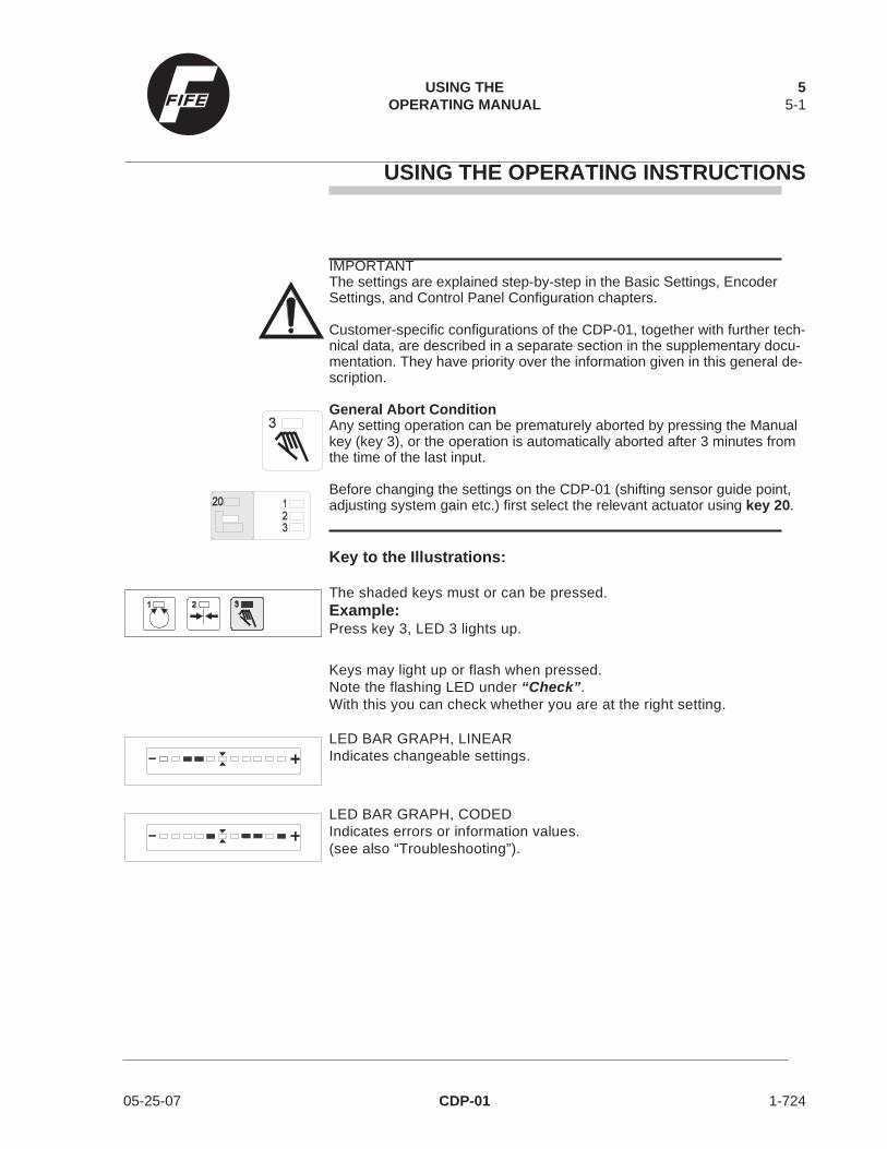
IMPORTANTThe settings are explained step-by-step in the Basic Settings, EncoderSettings, and Control Panel Configuration chapters.
Customer-specific configurations of the CDP-01, together with further tech-nical data, are described in a separate section in the supplementary docu-mentation. They have priority over the information given in this general de-scription.
General Abort ConditionAny setting operation can be prematurely aborted by pressing the Manualkey (key 3), or the operation is automatically aborted after 3 minutes fromthe time of the last input.
Before changing the settings on the CDP-01 (shifting sensor guide point,adjusting system gain etc.) first select the relevant actuator using key 20.
Key to the Illustrations:
The shaded keys must or can be pressed.Example:Press key 3, LED 3 lights up.
Keys may light up or flash when pressed.Note the flashing LED under “Check”.With this you can check whether you are at the right setting.
LED BAR GRAPH, LINEARIndicates changeable settings.
LED BAR GRAPH, CODEDIndicates errors or information values.(see also “Troubleshooting”).
USING THE 5OPERATING MANUAL 5-1
05-25-07 CDP-01 1-724

THIS PAGE INTENTIONALY LEFT BLANK 1-724 CDP-01 05-25-07

CONTROL PANEL DESCRIPTION
IMPORTANTCustomer-specific configurations of the CDP-01, together with further tech-nical data, are described in a separate section in the supplementary docu-mentation. They have priority over the information given in this generaldescription.
Operating Modes
AutomaticWeb position errors are automatically corrected. The LED bar graph in-dicates the web position in the sensor.
Servo CenterThe guide moves the control rollers to the center position, i.e. the con-trol rollers are parallel to the production line rollers.The sensor positioning device moves the sensors to their retractposition.
ManualActuator is manually controlled using the +/- key.
Function Keys
F1;F2;F3Customer-specific special functions.Otherwise these keys are used for special settings.
ASCThe lockout or deadband function is switched ON and OFF with theASC key. With the ASC selected and in the LOCKOUT option of opera-tion, the guide will operate normally as long as the web is in the de-fined field of view of the sensor. If the sensor looses the web for anyreason, i.e. web tear out or end of roll, then the system goes into lock.When the web is re-established in the field-of-view of the sensor, thenthe system returns to AUTOMATIC.
CONTROL PANEL DESCRIPTION 66-1
05-25-07 CDP-01 1-727

Sensor Key
You can choose between the sensors connected to the CDP-01 by re-peatedly pressing the Sensor key. Only possible in Manual and ServoCenter modes.
Sensor for edge guidingLEFT sensor mode.
Sensor for edge guidingRight sensor mode.
Sensor for edge guidingCenter Guiding sensor mode.
Sensor for line guidingLine Center Guiding sensor mode.
Sensor for line edge guidingLine Edge Guiding sensor mode.
Sensor for special guidingSpecial guiding sensor mode.
IMPORTANT:This sensor selection can also be restricted specific to customerrequirement.
Setup Key
Used for changing basic settings and special settings. Only possible inManual mode. By pressing the key you can choose between the follow-ing options.
Automatic calibrationAutomatic calibration of the basic settings.(sensor guide point, system gain, polarity)
6 CONTROL PANEL DESCRIPTION6-2
1-727 CDP-01 05-25-07

Sensor guide pointManual adjustment of the sensor guide point.
System gainManual adjustment of the guide sensitivity of the guide or actuator.
PolarityManual adjustment of the guide direction of the guide or actuator.
Special Keys
+/- keyTo move the guide or actuator manually.To adjust system parameters.
Actuator selector keySelection of an actuator and the components assigned to the actuator.If the application permits, up to three actuators can be selected.
IMPORTANTBefore changing the settings on the CDP-01 (shifting sensor guidepoint, adjusting system gain etc.) first select the relevant actuator usingkey 20.
CONTROL PANEL DESCRIPTION 66-3
05-25-07 CDP-01 1-727

THIS PAGE INTENTIONALY LEFT BLANK 1-727 CDP-01 05-25-07

BASIC SETTINGS
This chapter covers all relevant settings for normal operation of the system.
BASIC SETTINGS 77-1
05-25-07 CDP-01 / Firmware Version 2.x 1-728

Sensor Selection Multi-DriveEdge Guiding
IMPORTANTThese instructions are for standard applications. For special applicationssee other instructions provided with order. Connect CDP as shown in Fig.1 of this chapter. Sensor selection must correspond to the selected drive.
a. Set Manual mode.
b. Select Drive 1.
Press key 20 until the drive 1 LED is lit.
c. Press Sensor key until Sensor LED 10 (Port X1) is lit.
Verify that the correct sensor is selected for drive 1 by blocking a portion ofthe sensor viewing area and noting whether the LED bar graph changes. Ifthe LED bar graph does not change check correct sensor connections andrepeat verification process..
d. Select Drive 2.
Press key 20 until the drive 2 LED is lit.
e. Press Sensor key until Sensor LED 9 (Port X2) is lit.
Verify that the correct sensor is selected for drive 2 by blocking a portion ofthe sensor viewing area and noting whether the LED bar graph changes. Ifthe LED bar graph does not change select another sensor and repeat verifi-cation process.
f. Select Drive 3.
3 drive system only (CDP-01-MMM).Press key 20 until the drive 3 LED is lit.
g. Press Sensor key until Sensor LED 12 (Port X3) is lit.
Verify that the correct sensor is selected for drive 3 by blocking a portion ofthe sensor viewing area and noting whether the LED bar graph changes. Ifthe LED bar graph does not change check correct sensor connections andrepeat verification process.
7 BASIC SETTINGS7-2
1-728 CDP-01 / Firmware Version 2.x 05-25-07

Sensor Selection Mutli-DriveCenter Guiding
Two Drive Center GuidingCDP-01-MM
IMPORTANTThese instructions are for standard applications. For special applicationssee other instructions provided with order. Connect the CDP as shown inFig. 2.
a. Set Manual mode.
b. Select Drive 1.
Press key 20 until the drive 1 LED is lit.
c. Press Sensor key until Sensor LED 9 (Port X2) and 10 (Port X1)are lit.
Verify that the correct sensors are selected for drive 1 by blocking a portionof each sensor’s viewing area and noting whether the LED bar graphchanges. If the LED bar graph does not change check and correct sensorconnections and repeat step c.
d. Select Drive 2.Press key 20 until the drive 2 LED is lit.
e. Press Sensor key until Sensor LED 11 and 12 (Port X3) are lit.
Verify that the correct sensors are selected for drive 2 by blocking a portionof each sensor’s viewing area and noting whether the LED bar graphchanges. If the LED bar graph does not change check and correct sensorconnections and repeat step e.
BASIC SETTINGS 77-3
05-25-07 CDP-01 / Firmware Version 2.x 1-728
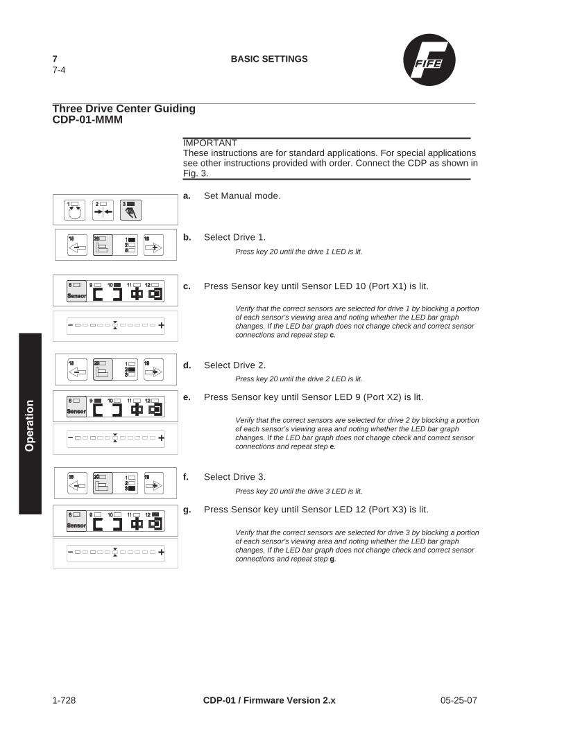
Three Drive Center GuidingCDP-01-MMM
IMPORTANTThese instructions are for standard applications. For special applicationssee other instructions provided with order. Connect the CDP as shown inFig. 3.
a. Set Manual mode.
b. Select Drive 1.
Press key 20 until the drive 1 LED is lit.
c. Press Sensor key until Sensor LED 10 (Port X1) is lit.
Verify that the correct sensors are selected for drive 1 by blocking a portionof each sensor’s viewing area and noting whether the LED bar graphchanges. If the LED bar graph does not change check and correct sensorconnections and repeat step c.
d. Select Drive 2.Press key 20 until the drive 2 LED is lit.
e. Press Sensor key until Sensor LED 9 (Port X2) is lit.
Verify that the correct sensors are selected for drive 2 by blocking a portionof each sensor’s viewing area and noting whether the LED bar graphchanges. If the LED bar graph does not change check and correct sensorconnections and repeat step e.
f. Select Drive 3.
Press key 20 until the drive 3 LED is lit.
g. Press Sensor key until Sensor LED 12 (Port X3) is lit.
Verify that the correct sensors are selected for drive 3 by blocking a portionof each sensor’s viewing area and noting whether the LED bar graphchanges. If the LED bar graph does not change check and correct sensorconnections and repeat step g.
7 BASIC SETTINGS7-4
1-728 CDP-01 / Firmware Version 2.x 05-25-07

X1
CDP-01-MMM
X2X3
Figure 1
X1X2X3
CDP-01-MM
VTB-20
Figure 2
X3
CDP-01-MMM
SDA-20
X2
SDA-20 SDA-20
X1
Figure 3
EdgeGuiding2 or 3 Drives
CenterGuiding2 Drives
CenterGuiding3 Drives
Drive 3Sensor
Drive 2Sensor
Drive 1Sensor
Drive 3Sensors
Drive 2Sensors
Drive 1Sensors
Drive 2Sensors
Drive 1Sensors
BASIC SETTINGS 77-5
05-25-07 CDP-01 / Firmware Version 2.x 1-728

Shifting the Sensor GuidePoint with the Web in Mo-tion
The sensor guide point is shifted within the sensor proportional band.
a. Set Automatic mode.
b. Press Setup key repeatedly until LEDs (13 and 15) light up.
Check: LED (1) flashes.
c. Change sensor guide point using + or - key.
You may return to center by pressing F1 and F2 simultaneously.LED bar graph indicates current sensor guide point position.The new settings are immediately visible.
d. Save setting,
OR
Cancel setting.Setting is not saved.
7 BASIC SETTINGS7-6
1-728 CDP-01 / Firmware Version 2.x 05-25-07

Changing the System Gainwith the Web in Motion
The system gain changes the guide sensitivity of the actuator.
a. Set Automatic mode.
b. Press Setup key repeatedly until LEDs (13 and 16) light up.Check: LED (1) flashes.
c. Change system gain using + or - key.
You may set system gain to 1 by pressing F1 and F2 simultaneously.LED bar graph indicates current system gain.The new settings are immediately visible.
d. Save setting,
OR
Cancel setting.Setting is not saved.
BASIC SETTINGS 77-7
05-25-07 CDP-01 / Firmware Version 2.x 1-728

Sensor Calibration WithEdge Sensors
The sensor is calibrated to the web opacity.
IMPORTANTDo this procedure only when the web is not opaque or when web opacitychanges. Factory settings arefor opaque webs.
IMPORTANTCalibration is easier with the RCAL-20 control panel. RCAL-20 is one ofthe CDP-01 accessories.
a. Set Manual mode.
b. Press Setup key.
Check: LED (3) flashes.
c. Press Sensor key once, then repeatedly until relevant sensor
d. Remove web material fully from sensor proportional band.
The actuator can be remotely controlled using the + or - key to remove theweb from the sensor proportional band.
e. Press F1.
f. Bring web material fully into sensor proportional band.
The actuator can be remotely controlled using the + or - key to bring the webinto the sensor proportional band.
g. Press F2.
LED bar graph indicates contrast. If the contrast is too low an error messageis displayed (left and right outer LEDs flash).
h. Save setting,
OR
Cancel setting.Setting is not saved.
7 BASIC SETTINGS7-8
1-728 CDP-01 / Firmware Version 2.x 05-25-07

Sensor Calibration withLine Sensor SE-26
Areas of application
The SE-26 line sensor can be used for the following web guiding appli-cations:
To detect a material edge or print edge. A print edge must be at least0.08 in (2 mm) wide.
To detect a line center. The width of a line may vary between 0.04 to0.10 in (1 to 2.5 mm). The gap to adjacent prints must not fall below0.10 in (2.5 mm).
To detect a broken print edge. A print edge must be at least 0.08 in (2mm) wide.
To detect a broken line. The width of a line may vary between 0.04 to0.10 in (1 to 2.5 mm). The gap to adjacent prints must not fall below0.10 in (2.5 mm).
In sensor calibration the line sensor is calibrated to the color contrast.Before sensor calibration, the distance between the sensor and the ma-terial must be set so that the light spot of the line sensor is shown insharp focus. In the following, sensor calibration is described for the re-spective applications.
IMPORTANTCalibration is easier with the RCAL-26 control panel. RCAL-26 is one ofthe CDP-01 accessories.
BASIC SETTINGS 77-9
05-25-07 CDP-01 / Firmware Version 2.x 1-728

Calibrating to Detect a Material Edge or a Print Edge
a. Set Manual mode.
b. Press Setup key.Check: LED (3) flashes.
c. Press Sensor key repeatedly until LEDs (8 and 12) light up.
d. Position light spot fully on the line (material).
e. Press F1.
f. Position light spot fully on the background.
g. Press F2.
LED bar graph indicates contrast. If the contrast is too low an error messageis displayed (left and right outer LEDs flash).
h. Save setting,
OR
Cancel setting.Setting is not saved.
Light spot
Web
Light spot
Web
7 BASIC SETTINGS7-10
1-728 CDP-01 / Firmware Version 2.x 05-25-07

Calibrating to Detect a Line Center
a. Set Manual mode.
b. Press Setup key.
Check: LED (3) flashes.
c. Press Sensor key repeatedly until LEDs (8 and 11) light up.
d. Position line at left edge of light spot (line within light spot).
e. Press F1.
f. Position line at right edge of light spot (line within light spot).
g. Press F2.
LED bar graph indicates contrast. If the contrast is too low an error messageis displayed (left and right outer LEDs flash).
h. Save setting,
OR
Cancel setting.Setting is not saved.
Light spot
Web
Light spot
Web
BASIC SETTINGS 77-11
05-25-07 CDP-01 / Firmware Version 2.x 1-728

Calibrating to Detect a Broken Print Edge
a. Press ASC key repeatedly until LED (7) lights up or flashes.
The ASC function is usually pre-set at FIFE factory for the SE-26 line sen-sor. However, the correct setting is again described under “SE-26" in thesection on ”Setting the Sensor Proportional Band".
b. Now carry out calibration as described earlier under “Calibratingto Detect a Material Edge or a Print Edge”.
Calibrating to Detect a Broken Line
a. Press ASC key repeatedly until LED (7) lights up or flashes.
The ASC function is usually pre-set at FIFE factory for the SE-26 line sen-sor. However, the correct setting is again described under “SE-26" in thesection on ”Setting the Sensor Proportional Band".
b. Set Manual mode.
c. Press Setup key.
Check: LED (3) flashes.
d. Press Sensor key repeatedly until LEDs (8 and 12) light up.
e. Position line in center of light spot.
f. Press F1.
g. Position light spot fully on background.
Light spot
Web
Light spotWeb
7 BASIC SETTINGS7-12
1-728 CDP-01 / Firmware Version 2.x 05-25-07

h. Press F2.
LED bar graph indicates contrast. If the contrast is too low an error messageis displayed (left and right outer LEDs flash).
i. Save setting,
OR
Cancel setting.Setting is not saved.
IMPORTANTGuiding is executed with sensor selection: LED (11).
j. Now carry out calibration as described earlier under“Calibrating to Detect a Line Center”.
BASIC SETTINGS 77-13
05-25-07 CDP-01 / Firmware Version 2.x 1-728

Automatic Calibration
The guide sensitivity, polarity and sensor guide point are automaticallycalibrated.
IMPORTANTAutomatic calibration must be carried out with the web at a standstill.If the SE-26 line sensor is operated in “Line Center Guiding” sensormode, the following two sensor calibrations must be carried out beforeautomatic calibration:- “Calibrating to Detect a Line Center”,- and “Calibrating to Detect a Material Edge or a Print Edge”.
a. Set Manual mode.
b. Select actuator.
If LED (3) is no longer lit, repeat step a.
c. Press Setup key repeatedly until LEDs (13 and 14) light up.
Check: LED (3) flashes.
d. Press Sensor key repeatedly until relevant sensor LED lights up.
e. Bring web material into sensor proportional band so that halfof the sensor proportional band is covered. The center LEDon the LED bar graph and LED (7) in ASC key light up. Auto-matic calibration is not possible while LED (7) is flashing.
The actuator can be remotely controlled using the + or - key to bring the webinto the sensor proportional band.
f. Start automatic calibration.
IMPORTANT:System begins to vibrate. Sensor guide point and optimum systemgain are being set. On completion of calibration the processor isready for automatic guiding mode.
OR
Cancel setting.Automatic calibration is not carried out.
Edge guiding
Center guiding
7 BASIC SETTINGS7-14
1-728 CDP-01 / Firmware Version 2.x 05-25-07
Shifting the Sensor GuidePoint with the Web atStandstill
The sensor guide point is shifted within the sensor proportional band.
a. Set Manual mode.
b. Select actuator.
If LED (3) is no longer lit, repeat step a.
c. Press Setup key repeatedly until LEDs (13 and 15) light up.
Check: LED (3) flashes.
d. Press Sensor key repeatedly until relevant sensor LED lights up.
e. Change sensor guide point using + or - key.
LED bar graph indicates current sensor guide point position.The new settings are visible only after moving to Automatic mode.Return to center by pressing F1 and F2 simultaneously.
Continue from step d to set more sensors, if required.
f. Save settings,
OR
Cancel setting.Setting is not saved.
BASIC SETTINGS 77-15
05-25-07 CDP-01 / Firmware Version 2.x 1-728

Changing the System Gainwith the Web at Standstill
The system gain changes the guide sensitivity of the actuator.
a. Set Manual mode.
b. Select actuator.
If LED (3) is no longer lit, repeat step a.
c. Press Setup key repeatedly until LEDs (13 and 16) light up.
Check: LED (3) flashes.
d. Press Sensor key repeatedly until relevant sensor LED lights up.
e. Change system gain using + or - key.
LED bar graph indicates current system gain.The new settings are visible only after moving to Automatic mode.Set system gain to 1 by pressing F1 and F2 simultaneously.
Continue from step d to set more sensors, if required.
f. Save settings,
OR
Cancel setting.Setting is not saved.
Changing the GuideDirection
The direction of the guide, or actuator, is changed.
The guide direction is dependent on the selected sensor.The polarity is changed in processing of the sensor signal.
7 BASIC SETTINGS7-16
1-728 CDP-01 / Firmware Version 2.x 05-25-07

a. Set Manual mode.
b. Select actuator.
If LED (3) is no longer lit, repeat step a.
c. Press Setup key repeatedly until LEDs (13 and 17) light up.
Check: LED (3) flashes.
d. Press Sensor key repeatedly until relevant sensor LED lights up.
e. Change guide direction using + or - key.
LED bar graph indicates current guide direction.The new settings are visible only after moving to Automatic mode.
Continue from step d to set more sensors, if required.
f. Save settings,
OR
Cancel setting.Setting is not saved.
Setting the SensorProportional Band
With the ASC key a specific range in the sensor proportional band isactivated (switched ON or OFF). The LOCKOUT option is factory se-lected and the range is pre-set but can be changed.There are two setting options:either deadband or lockout.
Deadband:If the web is in the deadband, no guiding occurs. If the web is outsidethe deadband, it is guided. Select the DEADBAND option ONLY if theweb has ragged edges.
Lockout:The sensor proportional band is limited.If the web is within the limited sensor proportional band, it is guided. Ifthe web goes beyond the limited sensor proportional band no guidingoccurs , LED (7) flashes, and the system is in MANUAL.
Sensor
BASIC SETTINGS 77-17
05-25-07 CDP-01 / Firmware Version 2.x 1-728

Setting the Deadband
a. Set Manual mode.
b. Select actuator.
If LED (3) is no longer lit, repeat step a.
c. Press Setup key.
Check: LED (3) flashes.
d. Press ASC key.
e. Press Sensor key repeatedly until relevant sensor LED lights up.
f. Press F1 and F2 simultaneously.
Select deadband setting.
g. Set deadband range using + or - key.
The fewer LEDs are lit on the LED bar graph, the smaller the deadband.Continue from step e to set more sensors, if required.
h. Save settings,
OR
Cancel setting.Setting is not saved.
Setting the Lockout With Edge Sensors (For Line Sensor SE-26 see “Setting TheLockout For Line Sensor SE-26")
a. Set Manual mode.
7 BASIC SETTINGS7-18
1-728 CDP-01 / Firmware Version 2.x 05-25-07

b. Select actuator.
If LED (3) is no longer lit, repeat step a.
c. Press Setup key.
Check: LED (3) flashes.
d. Press ASC key.
e. Press Sensor key repeatedly until relevant sensor LED lights up.
f. Press F1.
Select lockout.
g. Set first side of sensor proportional band using + or - key.
The limits of the sensor proportional band light up on the LED bar graph.
h. Press F2.
Select lockout.
i. Set second side of sensor proportional band using + or - key.
The limits of the sensor proportional band light up on the LED bar graph.
Continue from step e to set more sensors, if required.
j. Save settings,
OR
Cancel setting.Setting is not saved.
DANGERThe actuator may still move due to external forces, despite the lockout.
BASIC SETTINGS 77-19
05-25-07 CDP-01 / Firmware Version 2.x 1-728

Setting the Lockout For Line Sensor SE-26
a. Set Manual mode.
b. Select actuator.
If LED (3) is no longer lit, repeat step a.
c. Press Setup key.
Check: LED (3) flashes.
d. Press ASC key.
e. Press sensor key repeatedly until LED (12) lights up.
f. Press F1 key.
Select lockout.
g. Using the + or - key, set the left side of the sensor proportionalband to the limits as shown on the LED bar graph here at the left.
h. Press F2.
Select lockout.
i. Using the + or - key, set the right side of the sensor proportionalband to the limits as shown on the LED bar graph here at the left.
j. Save settings,
OR
Cancel setting.Setting is not saved.
7 BASIC SETTINGS7-20
1-728 CDP-01 / Firmware Version 2.x 05-25-07

k. Press sensor key repeatedly until LED (11) lights up.
l. Press F1 key.
Select lockout.
m. Using the + or - key, set the left side of the sensor proportionalband to the limits as shown on the LED bar graph here at the left.
Hold the key down for 10 seconds longer to make sure the maximum settingis reached.
n. Press F2.
Select lockout.
o. Using the + or - key, set the right side of the sensor proportionalband to the limits as shown on the LED bar graph here at the left.
p. Save settings,
OR
Cancel setting.Setting is not saved.
DANGERThe actuator may still move due to external forces, despite the lockout.
BASIC SETTINGS 77-21
05-25-07 CDP-01 / Firmware Version 2.x 1-728
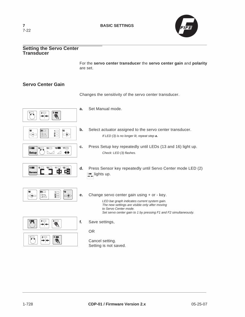
Setting the Servo CenterTransducer
For the servo center transducer the servo center gain and polarityare set.
Servo Center Gain
Changes the sensitivity of the servo center transducer.
a. Set Manual mode.
b. Select actuator assigned to the servo center transducer.
If LED (3) is no longer lit, repeat step a.
c. Press Setup key repeatedly until LEDs (13 and 16) light up.
Check: LED (3) flashes.
d. Press Sensor key repeatedly until Servo Center mode LED (2)lights up.
e. Change servo center gain using + or - key.
LED bar graph indicates current system gain.The new settings are visible only after movingto Servo Center mode.Set servo center gain to 1 by pressing F1 and F2 simultaneously.
f. Save settings,
OR
Cancel setting.Setting is not saved.
7 BASIC SETTINGS7-22
1-728 CDP-01 / Firmware Version 2.x 05-25-07

Servo Center Polarity
The direction of the guide, or actuator, is changed.
The guide direction is dependent on the selected servo center transducer. The polarity is changed inprocessing of the servo center transducer signal.
a. Set Manual mode.
b. Select actuator assigned to the servo center transducer.
If LED (3) is no longer lit, repeat step a.
c. Press Setup key repeatedly until LEDs (13 and 17) light up.
Check: LED (3) flashes.
d. Press Sensor key repeatedly until Servo Center mode LED (2)lights up.
e. Change polarity using + or - key.
LED bar graph indicates current polarity.The new settings are visible only after moving to Servo Center mode.
f. Save settings,
OR
Cancel setting.Setting is not saved.
BASIC SETTINGS 77-23
05-25-07 CDP-01 / Firmware Version 2.x 1-728

THIS PAGE INTENTIONALY LEFT BLANK 1-728 CDP-01 05-25-07
CONTROL PANEL CONFIGURATION
Allows individual adaptation of the control panel to the needs of thecustomer.Erroneous inputs are prevented by disabling unneeded modes. Somelocal regulations also stipulate that certain functions must be disabledfor each individual operating mode.
CONTROL PANEL CONFIGURATION 88-1
05-25-07 CDP-01 / Firmware Version 2.x 1-729

Restricting SensorSelection,Disabling Servo CenterFunction
If not all sensor connections in a system are needed, it is advisable torestrict sensor selection. It is also advisable to disable the Servo Cen-ter mode if no servo center transducer is installed.
(De)activatable sensor modes:
Left edge
Right edge
Both edges (total/difference)
Line
Line edge
Both line types (total/difference)
Servo Center
a. Set Manual mode.
b. Select actuator.
If LED (3) is no longer lit, repeat step a.
c. Press Setup key.
d. Press +/- keys simultaneously.Check: LED (13) flashes.
e. Press Sensor key repeatedly until sensor mode to be (de)acti-vated or Servo Center mode is displayed.
Check: LEDs (8, 13) flash.
f. The selected mode is activated or deactivated as appropriate bypressing F1.
LED (4) indicates the active state.
If two sensor signals are interlinked, the + or - key can be used to choose be-tween total and difference formation.
8 CONTROL PANEL CONFIGURATION8-2
1-729 CDP-01 / Firmware Version 2.x 05-25-07

Total formation for sensor positioning.Difference formation for center guiding.
Continue with step e to switch more sensor modes or the Servo Center func-tion ON/OFF, if required.
g. Save setting,
OR
Cancel setting.Setting is not saved.
Switching ManualActuator Motion On/Off
The +/- key allows the actuators to be manually moved in Automatic,Servo Center and Manual modes. This function can be enabled and dis-abled individually for each mode. A side-effect is that all sensor guidepoints of the selected actuator are set to center. The sensor guidepoint can be re-adjusted subsequently.
a. Set Manual mode.
b. Select actuator.If LED (3) is no longer lit, repeat step a.
c. Press Setup key.
d. Press +/- keys simultaneously.Check: LED (13) flashes.
e. Press Setup key.Check: LEDs (1, 2, 3, 13) flash.
f. The +/- key function is switched ON/OFF by pressing an F key.
The LED in the F key indicates the active state, with the followingassignment:F1 for Automatic mode.F2 for Servo Center mode.F3 for Manual mode.
CONTROL PANEL CONFIGURATION 88-3
05-25-07 CDP-01 / Firmware Version 2.x 1-729

g. Save setting,
OR
Cancel setting.Setting is not saved.
Assigning +/- Key and Di-rection of Motion
Set the assignment of the direction of motion to the +/- keys. A side-ef-fect is that all sensor guide points of the selected actuator are set tocenter. The sensor guide point can be re-adjusted subsequently.
a. Set Manual mode.
b. Select actuator.
If LED (3) is no longer lit, repeat step a.
c. Press Setup key.
d. Press +/- keys simultaneously.
Check: LED (13) flashes.
e. Press Setup key.
Check: LEDs (1, 2, 3, 13) flash.
f. Set assignment of direction of motion with + or - key.
Lit LED on LED bar graph indicates current assignment.
8 CONTROL PANEL CONFIGURATION8-4
1-729 CDP-01 / Firmware Version 2.x 05-25-07

g. Save setting,
OR
Cancel setting.Setting is not saved.
Assigning Direction of Dis-play of LED Bar Graph
In AUTOMATIC and MANUAL modes the LED bar graph indicates theweb motion within the sensor proportional band. The assignment of thedirection of display to the web motion can be altered separately foreach sensor.
ImportantBefore this assignment is changed the guide direction of the actuator(page 7-16) and the assignment of the +/- key (page 8-4) must becorrectly set, as those two settings also affect the direction of display.
a. Set Manual mode.
b. Select actuator.
If LED (3) is no longer lit, repeat step a.
c. Press Setup key.
d. Press +/- keys simultaneously.
Check: LED (13) flashes.
e. Press Setup key 3 times.
Check: LEDs (1, 3, 13) flash.
f. Select sensor.
g. Change direction of display using + or - key.Continue from step f to set more sensors, if required.
CONTROL PANEL CONFIGURATION 88-5
05-25-07 CDP-01 / Firmware Version 2.x 1-729

h. Save setting,
OR
Cancel setting.Setting is not saved.
8 CONTROL PANEL CONFIGURATION8-6
1-729 CDP-01 / Firmware Version 2.x 05-25-07

ENCODER SETTINGS
The CDP-01 offers the option of equipping each actuator with an en-coder for position detection. This enables position monitoring andevaluation.In most applications the encoder is used in conjunction with a sensorpositioning assembly.Encoder settings are usually pre-set at FIFE factory, so that resettingis not necessary. In the case of spare parts deliveries the CDP-01 isnot normally pre-set.
ENCODER SETTINGS 99-1
05-25-07 CDP-01 / Firmware Version 2.x 1-732

Defining Displacement Lim-its, Limiting Stroke
The internal displacement limits for the position of the selected actua-tor are set and standardized. The displacement and stroke of that ac-tuator is limited.
IMPORTANTThe servo center transducer must be located in the adjacent range of mo-tion, so that the center position can also be reached in Servo Centermode.
DANGERNew crushing and shearing points may be created by changing or cancel-ling the stroke limitation, and/or mechanical stops may be damaged ordestroyed.
a. Set Manual mode.
b. Select actuator.
If LED (3) is no longer lit, repeat step a.
c. Set Servo Center mode and wait until center position is reached.
d. Set Manual mode.
e. Press Setup key.
f. Press +/- keys simultaneously.
Check: LED (13) flashes.
g. Press ASC key.
Check: LEDs (7, 13) flash.
If the F1, F2 and F3 key LEDs flash, the center position has not beenreached. Setting is not possible. Press F1 and F2 simultaneously to clearany existing stroke limitations. Press the Automatic key (1) and repeat theprocess, paying particular attention to step c.
h. Move to first maximum position using + or - key.
First maximum position in sensor positioning assemblies means move in op-posite direction to system centerline.
First maximum position in rotating frame means move toward actuator side.
9 ENCODER SETTINGS9-2
1-732 CDP-01 / Firmware Version 2.x 05-25-07

i. Pressing F1 sets the value for the position (stroke limitation 1).
j. Move to second maximum position using + or - key.
Second maximum position in sensor positioning assemblies means move to-ward system centerline.Second maximum position in rotating frame means move toward operatorside.
k. Pressing F2 sets the value for the position (stroke limitation 2).
l. Save setting,
OR
Cancel setting.Setting is not saved.
Calibrating the Encoder
The encoder value and the stroke of the actuator are balanced to eachother to calibrate mechanical tolerances.
IMPORTANTThis calibration should only be carried out if expressly stipulated in a sepa-rate customer-specific section in the supplementary documentation.
The encoder is calibrated in two steps:1. The travel distance is defined on the CDP-01.2. The defined travel distance is run precisely
and saved.
a. Set Manual mode.
b. Select actuator.
If LED (3) is no longer lit, repeat step a.
ENCODER SETTINGS 99-3
05-25-07 CDP-01 / Firmware Version 2.x 1-732

c. Press Setup key.
d. Press +/- keys simultaneously.
Check: LED (13) flashes.
e. Press ASC key.
Check: LEDs (7, 13) flash.
f. Press Setup key.
Check: LEDs (6, 7, 13) flash.
g. The travel distance is defined by pressing F3 repeatedly. Visibleon the LED bar graph; see Distance Selection Table later in thissection.
h. Move to starting point of travel distance using + or - key.
i. Press F1.Starting point of travel distance is saved.Mark starting point with a pencil.
j. Run the travel distance defined beforehand with the F3 key usingthe + or - key.
k. Press F2.
The end point of the travel distance is saved.If the left and right outer LEDs are flashing, the calibration range has beenexceeded. Setting is not possible. Mechanical modifications are required.Pressing F1 and F2 simultaneously causes the value to be reset to 0.002 in(0.05 mm) per encoder pulse.
l. Save setting,
OR
Cancel setting.Setting is not saved.
9 ENCODER SETTINGS9-4
1-732 CDP-01 / Firmware Version 2.x 05-25-07

Distance Selection Table(for encoders with 0.002 in (0.05 mm) resolution)
To improve accuracy, select the longest possible distance.
Setting Minimum and Maxi-mum Values
There is a further monitoring facility for the encoder values in the CDP-01 in addition to stroke limitation of the individual actuators. The totalvalue or the difference between several encoders can be monitored,and thus the positions of the actuators relative to each other. This func-tion is only effective if the CDP-01 has been specially configured for itprior to delivery. According to configuration, the encoder monitoring fa-cility can block an actuator or generate a signal which is made avail-able at connector (-X7).
Typical applications with sensor positioning assemblies with two inde-pendently controllable sensors: web width monitoring or collision pro-tection of the sensors.
IMPORTANTThis calibration only needs to be carried out when stipulated in a separatecustomer-specific section in the supplementary documentation.
The procedure “Defining Displacement Limits, Limiting Stroke”must be completed prior to this procedure (see earlier).
LED bar graph Distance
0.39 in (10 mm)
0.79 in (20 mm)
1.57 in (40 mm)
3.15 in (80 mm)
4.72 in (120 mm)
9.45 in (240 mm)
17.72 in (450 mm)
35.43 in (900 mm)
51.18 in (1300 mm)
70.87 in (1800 mm)
102.36 in (2600 mm)
ENCODER SETTINGS 99-5
05-25-07 CDP-01 / Firmware Version 2.x 1-732

Setting a Minimum Value, e.g. Collision Protection
a. Set Manual mode.
b. Pre-position all affected actuators.
c. Select actuator.
If LED (3) is no longer lit, repeat step a.
d. Press Setup key.
e. Press +/- keys simultaneously.
Check: LED (13) flashes.
f. Press ASC key.
Check: LEDs (7, 13) flash.
g. Press Setup key twice.
Check: LEDs (7, 13, left-hand LED on LED bar graph) flash.
h. Move actuator to desired position using + or - key.
For example, in sensor positioning assemblies, to the minimum distance atwhich the collision protection is to deactivate the actuator. If an already ac-tive limit prevents the desired positioning of the actuator, press F1 and F2 si-multaneously and continue from step l, “Save setting”. Then start againfrom the beginning, step a.
i. The value is saved by pressing F1.
Pressing F1 and F2 simultaneously causes the value to be reset, so that thefunction is disabled.
j. The “Block actuators” function can be switched ON and OFF bypressing F2. The LED in the F2 key is lit when the function is ac-tive.
When the function is inactive only an internal signal is generated which, ac-cording to configuration, is available at connector -X7.
k. Pressing F3 defines whether the blocking function prevents the ac-tuator from continuing moving to the left or to the right.
The right setting can only be determined by saving (see step l) and testing.
9 ENCODER SETTINGS9-6
1-732 CDP-01 / Firmware Version 2.x 05-25-07

l. Save setting,
OR
Cancel setting.Setting is not saved.
Setting a Maximum Value, e.g. Maximum Web Width
a. Set Manual mode.
b. Pre-position all affected actuators.
c. Select actuator.
If LED (3) is no longer lit, repeat step a.
d. Press Setup key.
e. Press +/- keys simultaneously.
Check: LED (13) flashes.
f. Press ASC key.
Check: LEDs (7, 13) flash.
g. Press Setup key 3 times.
Check: LEDs (7, 13, right-hand LED on LED bar graph) flash.
h. Move actuator to desired position using + or - key.
For example, in sensor positioning assemblies, to the maximum distance atwhich a web width alarm is to be triggered. If an already active limit preventsthe desired positioning of the actuator, press F1 and F2 simultaneously andcontinue from step l, “Save setting”. Then start again from the beginning,step a.
i. The value is saved by pressing F1.
Pressing F1 and F2 simultaneously causes the value to be reset, so that thefunction is disabled.
ENCODER SETTINGS 99-7
05-25-07 CDP-01 / Firmware Version 2.x 1-732
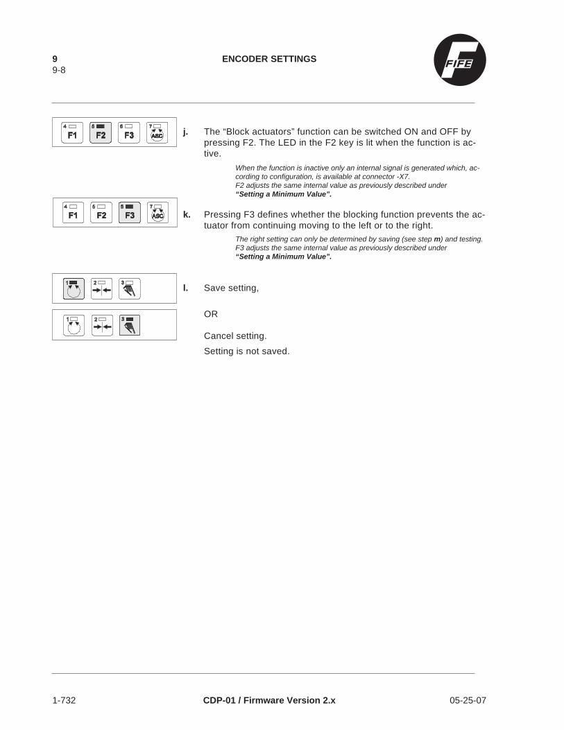
j. The “Block actuators” function can be switched ON and OFF bypressing F2. The LED in the F2 key is lit when the function is ac-tive.
When the function is inactive only an internal signal is generated which, ac-cording to configuration, is available at connector -X7.F2 adjusts the same internal value as previously described under“Setting a Minimum Value”.
k. Pressing F3 defines whether the blocking function prevents the ac-tuator from continuing moving to the left or to the right.
The right setting can only be determined by saving (see step m) and testing.F3 adjusts the same internal value as previously described under“Setting a Minimum Value”.
l. Save setting,
OR
Cancel setting.
Setting is not saved.
9 ENCODER SETTINGS9-8
1-732 CDP-01 / Firmware Version 2.x 05-25-07

SPECIAL SETTINGS
No special settings are generally required on the CDP-01.However, if required the following special settings can be made:
• Configure RGPC control panel.
• Set maximum speed of actuators.
• Configure system sensitivity of web speed(OPTIONAL).
• Set bus addresses for serial data communication.
• Configure alarm outputs.
• Set oscillation.
SPECIAL SETTINGS 1010-1
05-25-07 CDP-01 / Firmware Version 2.x 1-730

Configuring RGPCFunction
The control panels RGPC-20 and RGPC-21 are two of the CDP-01 ac-cessories, and are used for shifting the guide point in the sensor pro-portional band and for remote adjustment of the actuators in Manualmode. A side-effect is that all sensor guide points of the selected actua-tor are set to center. The sensor guide point can be re-adjusted sub-sequently.Setting possibilities:
• Switch remote adjustment function ON/OFF in Manual and Servo Cen-ter modes.
• Selection of shift range in sensor proportional band.
• Assignment of keys to the direction of motion of the actuator.
a. Set Manual mode.
b. Select actuator.
If LED (3) is no longer lit, repeat step a.
c. Press Setup key.
d. Press +/- keys simultaneously.
e. Press Setup key twice.
Check: LEDs (2, 3, 13) flash.
f. The RGPC keys can be switched ON/OFF for the Manual andServo Center modes by pressing F1. The LED in the F1 key is litwhen the function is active.
g. The shift range of the RGPC can be set to 40% by pressing F2.The LED in the F2 key is lit in this case. When the LED is not litthe factory default setting is in effect. For web edge sensors withsmall proportional bands the shift range is usually pre-set to 81%.
h. The key assignment of the RGPC can be altered by pressing the+ or - key.The LED bar graph indicates the key assignment.
+ LED = default.- LED = key assignment reversed.
10 SPECIAL SETTINGS10-2
1-730 CDP-01 / Firmware Version 2.x 05-25-07

i. Save setting,
OR
Cancel setting.Setting is not saved.
Setting Maximum Speed ofActuators
Changes the maximum shift speed of the actuators in all operatingmodes.
a. Set Manual mode.
b. Select actuator.
If LED (3) is no longer lit, repeat step a.
c. Press Setup key.
d. Press +/- keys simultaneously.
e. Press Setup key 4 times.
Check: LEDs (1, 13) flash.
f. Set maximum speed using + or - key.
LED bar graph indicates current maximum speed.
g. Save setting,
OR
Cancel setting.Setting is not saved.
SPECIAL SETTINGS 1010-3
05-25-07 CDP-01 / Firmware Version 2.x 1-730

Control by Web Speed
Couple the reaction speed of the guide to the web speed. Settings canonly be made on actuator 1, but the setting is also valid for other actua-tors.
IMPORTANTThis control function must be ordered separately. Please refer to your or-der confirmation to check on the specific product package.
a. Set Manual mode.
b. Select actuator 1.
If LED (3) is no longer lit, repeat step a.
c. Press Setup key.
d. Press +/- keys simultaneously twice.
Check: LEDs (13, 16) flash.
e. Set system to minimum web speed from which web guidingis to begin.
f. Press F1.Minimum value is saved.
g. Set system to maximum speed.
h. Press F2.
Maximum value is saved.If the difference between the minimum and maximum web speeds is too lowthe LED bar graph flashes.
i. Save setting,
OR
Cancel setting.Setting is not saved.
10 SPECIAL SETTINGS10-4
1-730 CDP-01 / Firmware Version 2.x 05-25-07

Serial DataCommunication
Set communication address for serial data communication. Only possi-ble for actuator 1.
a. Set Manual mode.
b. Select actuator 1.
If LED (3) is no longer lit, repeat step a.
c. Press Setup key.
d. Press +/- keys simultaneously twice.
e. Press Setup key.
Check: LEDs (13, 20-1) flash.
f. Address is set using + or - key.
LED bar graph indicates address.
g. Save setting,
OR
Cancel setting.Setting is not saved.
Configuring Alarm Outputs
For the alarm outputs delay times are set and the function of the out-puts is inverted. Only possible for actuator 1.
SPECIAL SETTINGS 1010-5
05-25-07 CDP-01 / Firmware Version 2.x 1-730

a. Set Manual mode.
b. Select actuator 1.
If LED (3) is no longer lit, repeat step a.
c. Press Setup key.
d. Press +/- keys simultaneously twice.
e. Press Setup key twice.
Check: LEDs (13, 15) flash.
f. Press F1.
Alarm output 1 is addressed.
g. The delay time for alarm output 1 is set by pressing and holdingdown the + or - key.
LED bar graph indicates delay time (0 to 22 seconds possible).
h. The function of output 1 is inverted by pressing F3.
i. Press F2
Alarm output 2 is addressed.
j. The delay time for alarm output 2 is set by pressing and holdingdown the + or - key.
LED bar graph indicates delay time (0 to 22 seconds possible).
k. The function of output 2 is inverted by pressing F3.
l. Save setting,
OR
Cancel setting.Setting is not saved.
10 SPECIAL SETTINGS10-6
1-730 CDP-01 / Firmware Version 2.x 05-25-07

Setting Oscillation
The oscillator function is only effective if the CDP-01 has been spe-cially configured for it prior to delivery.Pressing F1 activates the oscillator function.
The following two settings are possible:
• Set amplitude.The size of the web displacement is set (left/right motion of web).
• Set oscillation frequency.The number of web displacements over a certain time period is set.
IMPORTANTWhile ON, the oscillator function remains active as long as the MODE is inAUTO even if the web speed is stopped. The oscillator function will stop ifthe MODE is set to MANUAL or SERVO CENTER or if the external LOCKis energized. When returning to AUTO, the oscillator will continue from thepoint at which it stopped except from SERVO CENTER, then the oscilla-tor will begin at the original guide point. If the oscillator is turned OFFwhile in AUTO, the guide will return to the original guide point.
Setting Amplitude
a. Set Automatic mode.
b. The “Change in Amplitude” function is switched ON by pressingF2.
LED in the F2 key lit indicates function active.
c. Change amplitude using + or - key.
LED bar graph indicates current amplitude.
d. Save setting,
OR
Cancel setting.Setting is not saved.
SPECIAL SETTINGS 1010-7
05-25-07 CDP-01 / Firmware Version 2.x 1-730

Setting Oscillation Frequency
a. Set Automatic mode.
b. The “Change in Oscillation Frequency” function is switched ON bypressing F3.
LED in the F3 key lit indicates function active.
c. Change oscillation frequency using + or - key.
LED bar graph indicates current oscillation frequency.
d. Save setting,
OR
Cancel setting.
Setting is not saved.
10 SPECIAL SETTINGS10-8
1-730 CDP-01 / Firmware Version 2.x 05-25-07

TROUBLESHOOTING
The CDP-01 is designed in such a way that it detects any errors whichoccur and displays them on the LED strip in coded form. There are 3ways of displaying or activating the error code.
• If errors occur and are detected during power-up, the error code is dis-played immediately (see “Error Messages on Power-Up”).
• 5 LEDs in the bar graph are flashing, this indicates that one or more er-rors have been detected.The error code is only displayed on the LED bar graph when the Setupkey is pressed, and additional errors, if present, can be displayed us-ing the + or - key (see “Error Messages in Operation” and “Error Mes-sages after Automatic Calibration”).
• Not all errors are indicated by 5 flashing LEDs. As an alternative, theTroubleshooting mode can be activated to display the error code (see“Activating Troubleshooting Mode”).
TROUBLESHOOTING 1111-1
05-25-07 CDP-01 / Firmware Version 2.x 1-731

Frequent Setting Errors
The cause of incorrect or unwanted guiding is often an incorrect settingon the CDP-01. Such errors can be easily rectified by altering the rele-vant setting on the CDP-01. See table.
FAULT CAUSE CHECKS REMEDY
Servo centerposition notreached.
Polarity wrong. Check polarity. Change polarity.See Basic Settings.
Servo centertransducer receivingno signal.
Check distance from servocenter transducer tomeasuring point.
Attention: Danger ofcrushing
Disconnect the line plugwhen working on the servocenter transducer.
Adjust distance.
Servo center transducer ISCT-01air gap between transducer and actuator0.12 to 0.20 in (3 - 5 mm)
Servo center transducer ISCT-02air gap between transducer and actuator0.39 to 0.98 in (10 - 25 mm)
Servo center transducer ISCT-03air gap between transducer and actuator0.030 ± 0.015 in (0.8 ± 0.4 mm)
Encoder metersteps lost(only if encoder ispresent).
See “Restoring Encoder Meter steps ”later in this chapter".
Incorrectly setstroke limitations(only if encoder ispresent).
See “Encoder Settings” chapter 9,Defining Path Coordinates, LimitingStroke.
Servo centerposition reachedtoo slowly.
Servo center gaintoo low.
Check servo center gain. Change servo center gain. See BasicSettings.
Actuator movingin wrong direction.
Servo CenterPolarity(guide direction) foractuator and sensorwrong.
Check servo center polarity(guide direction).
Change guide direction. See BasicSettings.
Sensors can notbe selected.
Sensor selection isdisabled.
Activate sensor selection. See underControl Panel Configuration; RestrictingSensor Selection.
No sensor signal. Sensor, cable, plugfaulty or notconnected.
Check physical sensorsignal.
See under “Sensor Signal” later in thischapter.
System vibrates innormal operation.
System sensitivityset too high.
Change servo center gain. See BasicSettings.
Automaticcalibration notpossible at centerposition.(LED (7) flashing)
Sensor proportionalband incorrectlycovered.
Proportional bands of bothsensors must only be halfcovered by the material web.
Carry out automatic calibration. SeeBasic Settings.Note:In contrast to edge guiding the central LEDon the LED bar graph is lit if there is nomaterial in the sensor proportional band ofboth sensors.
11 TROUBLESHOOTING11-2
1-731 CDP-01 / Firmware Version 2.x 05-25-07

Activating Troubleshoot-ing Mode
Troubleshooting mode is activated to be able to display errors whichhave occurred in normal operation and after automatic calibration onthe LED bar graph in coded form.
a. Set Manual mode.
b. Press Setup key.
c. Press +/- keys simultaneously.
Check: LED (13) flashes.
d. Press F1 and F2 simultaneously.
Check: LEDs (4, 5, 13) flash.
Troubleshooting mode is activated.LED bar graph indicates display code/error code.
If all LEDs on the LED bar graph are lit, no error is present.
e. Additional errors can be displayed by pressing the + or - key.
f. Return to Manual mode.
TROUBLESHOOTING 1111-3
05-25-07 CDP-01 / Firmware Version 2.x 1-731

Error Messages on Power-Up
During power-up the CDP-01 checks internal values and displays themin coded form on the LED bar graph if an error is detected.
DISPLAY/ERROR CODE
CAUSE CHECKS REMEDY
Terminal mode active. Terminal connected withconfiguration software andconnection established.
Internal error Contact FIFE.
Internal error Contact FIFE.
one ormoreLEDslit
Internal error Contact FIFE.
(flashing)Error in normaloperation
Press Setup key. See “Error Messages inOperation”.
Error Messagesin Operation
During operation the CDP-01 checks internal values and indicates theoccurrence of one or more errors by means of 5 flashing LEDs. As analternative, the Troubleshooting mode can be activated to display theerror code.
DISPLAY/ERROR CODE
CAUSE CHECKS REMEDY
(flashing)Error occurred Press Setup key. See following notes on the
individual error messages.
Supply voltage beyondpermissible range.
Check correct line voltage. Establish stable line powersupply within the specifiedrange.
Actuator overcurrent Check actuators and theirleads for proper connectionand check for short-circuit ifnecessary
Connect actuators as persystem diagram,rectifyshort-circuit.
Error +12 V supply. Check for short-circuit bydisconnecting all connectorsone after the other.
Rectify short-circuit.
Error -12 V supply. Check for short-circuit bydisconnecting all connectorsone after the other.
Rectify short-circuit.
11 TROUBLESHOOTING11-4
1-731 CDP-01 / Firmware Version 2.x 05-25-07

DISPLAY/ERROR CODE
CAUSE CHECKS REMEDY
Internal supply voltage error. Check for short-circuit bydisconnecting all connectorsone after the other.
Rectify short-circuit.
Actuator not recognized. Check actuators and theirleads for proper connection.
Connect actuators as persystem diagram, or
Check correct part nos. ofactuators (older actuatorswithout characteristicresistance and cables withoutappropriate wires can not beused with CDP-01)
Replace actuators and cables.
Total output > 80 W. Check connected actuators.
Internal error. Contact FIFE.
Excess temperature insideCDP-01.
Improve cooling.
No error present.
Error Messages after Auto-matic Calibration
After automatic calibration the CDP-01 displays one of the following er-rors for 5 seconds.
DISPLAY/ERROR CODE
CAUSE CHECKS REMEDY
Internal automatic calibrationerror.
Contact FIFE.
Web edge not recognized inautomatic calibration.
Sensor calibration not carriedout.
Carry out sensor calibration.See Operating Manual,“Calibrating the Sensor”.
Web not in proportional band. Bring web into sensorproportional band.
Faulty connections. Connect sensors, actuatorsas per system diagram.
Mechanical stop notrecognized, or recognized tooearly, in automatic calibration.
When web in center of sensorproportional band, actuatortoo close to stop.
Center actuator, insert web,repeat calibration.
Actuator blocked orincorrectly connected.
Rectify blockage/connectionerror.
Too high sensor signal noisein automatic calibration.
Sensor poorly mounted orincorrectly connected,interference sources present.
Re-align sensor and/or rectifyconnection error,eliminate/shield interferencesources.Calibrate sensor SE-24manually.
TROUBLESHOOTING 1111-5
05-25-07 CDP-01 / Firmware Version 2.x 1-731

DISPLAY/ERROR CODE
CAUSE CHECKS REMEDY
Automatic calibration withControl by Web Speedactivated.
If possible, deactivate Controlby Web Speed function.CAUTIONSensitive web material maybe damaged during automaticcalibration. If necessary,adjust gain and guide pointmanually.
11 TROUBLESHOOTING11-6
1-731 CDP-01 / Firmware Version 2.x 05-25-07

Checking the Inputs andOutputs of the CDP-01
The signals passing through the inputs and outputs can be displayedon the LED bar graph. This can be used to check whether a signal ispresent.
Signal of Parallel Port (Socket -X7) andInput Devices RGPC-20, RGPC-21,RCAL-20, RCAL-26/1, RCAL-26/2.
a. Set Manual mode.
b. Press Setup key.
c. Press +/- keys simultaneously.
Check: LED (13) flashes.
d. Press F1 and F2 simultaneously.
Check: LEDs (4, 5, 13) flash.
e. Press Setup key.
Check: LEDs (6, 13) flash.
LED bar graph displays signals of parallel port. Continue from step f formore displays.
f. Switch LED display by pressing F3. LED display switch is indi-cated by the three left-hand LEDs (see Figure 1 further on).
Three left-hand LEDs on, signals for input devices RCAL-20 and RCAL-26displayed.
Three left-hand LEDs off, signals of parallel port and for input devicesRGPC-20 and RGPC-21 displayed.
Alarm output 1 is activated by pressing F1.
Alarm output 2 is activated by pressing F2.
Signal display on the LED bar graph for input devices is only enabled whena key has been pressed on the input device. For a detailed description ofwhich LEDs are displayed for which signals, see Figure 1 further on.
g. Return to Manual mode.
TROUBLESHOOTING 1111-7
05-25-07 CDP-01 / Firmware Version 2.x 1-731

L E D bar gr aph
L E D bar graph
2
2
11 TROUBLESHOOTING11-8
1-731 CDP-01 / Firmware Version 2.x 05-25-07

Sensor Signal
a. Set Manual mode.
b. Press Setup key.
c. Press Sensor key and select sensor.
d. Press F3.
e. Cover sensor proportional band. The physical sensor signal is dis-played on the LED bar graph.
ASC key on, displays physical sensor value from -20 to +20 mA.
F3 on, displays physical sensor value from 0 to 10 mA.
Servo Center Transducer SignalAttention: Danger of crushingAlways disconnect the cables of all actuators when working on the servocenter transducer.
a. Disconnect cables of all actuators.
b. Select actuator.
If LED (3) is no longer lit, repeat step a.
c. Set Servo Center mode.
d. Move a metal object in front of the servo center transducer.The servo center transducer signal is displayed on the LEDbar graph.
e. Return to Manual mode.
TROUBLESHOOTING 1111-9
05-25-07 CDP-01 / Firmware Version 2.x 1-731

Encoder Signal
DANGERDuring checking of the encoder signal the existing stroke limitations maybe exceeded. New crushing and shearing points may be created.
a. Set Manual mode.
b. Select actuator.
If LED (3) is no longer lit, repeat step a.
c. Press Setup key.
d. Press +/- keys simultaneously.
Check: LED (3) flashes.
e. Press ASC key.
Check: LEDs (4, 5, 6, 7, 13) flash.
f. The actuator and encoder are moved by pressing and holdingdown the + or - key. A lightstrip on the LED bar graph displays theencoder steps.
g. Return to Manual mode.
11 TROUBLESHOOTING11-10
1-731 CDP-01 / Firmware Version 2.x 05-25-07

Restoring Encoder MeterSteps
Encoder meter steps are lost as a result of:- mechanical movement when the system is switched off.- faulty encoders/encoder cables.- faulty mechanical connection of the encoder’s actuator
elements (toothed belts, pinions).
CHECKING
Activate Center mode.If the selected actuator cannot reach its center transducer (middle LEDon LED display does not light up), the actuator’s stroke limitations mustfirst be deactivated.
DANGERDeactivating the stroke limitations may result in new shearing and crush-ing points
a. Set Manual mode.
b. Select actuator.
If LED (3) is no longer lit, repeat step a.
c. Press the Setup key.
d. Press +/- keys simultaneously.
Check: LED (3) flashes.
e. Press ASC key.
Check: LED (4,5,6,7,13) flash.Stroke limitation is now deactivated.
f. Move the actuator by holding down the + or - key until the centertransducer is completely covered.
g. Set Manual mode.
h. Set Center mode.Meter steps are restored.
If the system vibrates above the center position, the servo center gain mustbe adjusted (see Chapter 7, section: Servo Center Gain).
TROUBLESHOOTING 1111-11
05-25-07 CDP-01 / Firmware Version 2.x 1-731

Display System Gain
The system gain can be displayed on the LED bar graph, from0 to 40 1/s. Automatic calibration must have first beensuccessfully completed.
a. Set Manual mode.
b. Press Setup key.
c. Press +/- keys simultaneously.
Check: LED (13) flashes.
d. Press F1 and F2 simultaneously.
Check: LEDs (4, 5, 13) flash.
e. Press Setup key twice.
Check: LEDs (4, 5, 13 and 16) flash.
f. Press Sensor key repeatedly until relevant sensor LED lights up.LED bar graph indicates system gain in 1/s for the selectedsensor mode.
g. Return to Manual mode.
Display Actuator,Display Firmware,Display FirmwareRevision
The
• actuator/motor type,
• firmware,
• and firmware revision
can be displayed on the LED bar graph in coded form.
11 TROUBLESHOOTING11-12
1-731 CDP-01 / Firmware Version 2.x 05-25-07
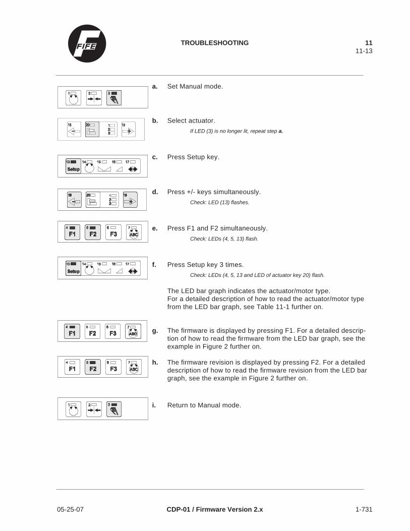
a. Set Manual mode.
b. Select actuator.
If LED (3) is no longer lit, repeat step a.
c. Press Setup key.
d. Press +/- keys simultaneously.
Check: LED (13) flashes.
e. Press F1 and F2 simultaneously.
Check: LEDs (4, 5, 13) flash.
f. Press Setup key 3 times.
Check: LEDs (4, 5, 13 and LED of actuator key 20) flash.
The LED bar graph indicates the actuator/motor type.For a detailed description of how to read the actuator/motor typefrom the LED bar graph, see Table 11-1 further on.
g. The firmware is displayed by pressing F1. For a detailed descrip-tion of how to read the firmware from the LED bar graph, see theexample in Figure 2 further on.
h. The firmware revision is displayed by pressing F2. For a detaileddescription of how to read the firmware revision from the LED bargraph, see the example in Figure 2 further on.
i. Return to Manual mode.
TROUBLESHOOTING 1111-13
05-25-07 CDP-01 / Firmware Version 2.x 1-731

Table 11-1
Figure 2
L E D bar graph
T he bar graphdisplays the value 2.1
L E D
LED bar graph Current Motor/Hydraulic Valve Typical Assembly
0.6 A 534741-001 Motor Pro-Trac 200
0.6 A 534740-001 Motor Pro-Trac 200
0.6 A 534735-001 Motor LA-2
0.6 A 534736-001 Motor Symat 25
1.3 A 534738-001/85626-001 Motor Symat 70/Symat 50
1.3 A 85627-001 Motor GAB-1, GAG-2, PT-200
1.6 A 534734-001 Motor GAB-1, GAG-2, PT-200
2.0 A 534737-001/85627-002 Motor LAB-3
3.5 A 44951-001/85626-002 Motor LRA
±50 mA Hydraulic Servo Valve
0.6 A Servo/Lockout Valve (48V)
1.2 A Servo/Lockout Valve (24 V)
±10 mA MPA-01 Motor Amplifier
±10 mA MPA-02 Motor Amplifier
No motor or valve detected
11 TROUBLESHOOTING11-14
1-731 CDP-01 / Firmware Version 2.x 05-25-07

INFORMATION
Technical Data
General
Line voltage 115 V +6%/-21% (90 ... 122 V)or 230 V +6%/-21% (180 ... 245 V)internally switchable without fuse change
Power consumption 210 VA.
Fuses 2 x 2.5 A 250 V time-lag, 0.20 x 0.79 in (5 x 20 mm).
Protection class IP 40.
DimensionsW 12.60 in (320 mm)D 7.28 in (185 mm)H 4.13 in (105 mm)Width, depth and mounting hole pattern identical to CSP-01.
Weight approx. 13 lbs (6 kg).
Ambient temperature 0 ... 50°C where mounted on nonmetal surface.0 ... 60°C on metal surface.
Supply to accessories +12 V ± 5%, 300 mA,-12 V ± 5%, 150 mA+5 V ± 5%, 1.6 A
Inputs and Outputs
Actuator Outputs (up to 3)Maximum total output 80 W at 30 V.SYMAT 25 or PROTRAC with belt drive requires 18 W.SYMAT 70 or PROTRAC with screw drive requires 39 W.LAB-3 requires 60 W and can only be operated as actuator 1.Lockout valve (24 V or 48 V) requires 28 W and can only be operatedas actuator 2 or 3. Outputs are short-circuit proof.
Current source -50 ... +50 mA per 100 Ohm for servo valveor -10 ... +10 mA for MPA and MPA lockout signal.Maximum 2 current source outputs per CDP-01 (actuator 1 OR actua-tor 2/3).Actuators 2 and 3 may each comprise a servo valve and lockout valve.
INFORMATION 1212-1
05-25-07 CDP-01 GENERAL INFORMATION 1-733

MPA lockout output to actuator 2/3 can be used as a switching output.Max. 30 V (open collector),55 mA at 1 V. Short-circuit proof.
Sensor Inputs (4)Maximum input range -20 ... +20 mA.Individually programmable; preferred range 0 ... 10 mA.Minimum difference between minimum and maximum input value1 mA. Highest minimum 10 mA.Load: 100 Ohm.Remote calibration devices can be connected(up to 4).± 12 V and +5 V available at sensor ports.
Serial PortRS-485, full duplex,+12 V and +5 V available at port.
Parallel Port6 parallel digital inputs referenced to ground.Low level: 0 ... 0.9 V.High level: 3.6 ... 24 V, max. 6 mA.2 open-collector outputs connected to ground, max. 30 V(open collector), 55 mA at 1.6 V.Short-circuit proof.1 analog web speed input,0 ... 10 mA per 100 Ohm+11.4 V ± 10% available at portMax. 300 mA (component of +12 V supply).
Servo Center Transducer/Position Encoder Inputs (up to 3)Servo center transducer input for connection of ISCT-01/02/03.
Quadratic incremental position encoder input (phases A and B):Low level: 0 ... 1.8 V.High level: 9.6 ... 12 V.Load 12 mA in switching, 0.001 A static.Maximum frequency 10 KHz.+11.4 V ± 10% available at ports.Max. 300 mA (component of +12 V supply).
RGPC PortFor connection of guide point remote controls RGPC-20/21.Up to 2 RGPC-21s can be connected in series with 1 RGPC-20.
12 INFORMATION12-2
1-733 CDP-01 GENERAL INFORMATION 05-25-07

Maximum Cable Lengths between CDP-01 and Accessories
Electromechanical drives:46 ft with 22 AWG (14 m with 0.357 mm2) or66 ft with 20 AWG (20 m with 0.5 mm2) or98 ft with 18 AWG (30 m with 0.75 mm2) cable
MPA or hydraulic servo valves and lockout valves:165 ft (50 m)
Sensors -SE-11/-12/-15/-16/-17/-20/-22/-23/-24, GSE-4000W1:
165 ft (50 m)
PIW-01/-0298 ft (30 m)
GLS-01/-02, SE-2649 ft (15 m)
Serial port according to application. Generally connection and termina-tion box FNET-20 is required. Maximum cable length between CDP-01and FNET-20:
11.81 in (300 mm)
Parallel port165 ft (50 m)
Position encoder98 ft (30 m)
ISCT with position encoder or directly connected to CDP-0149 ft (15 m)
RGPC -With 2 RGPC-21 and 1 RGPC-20
198 ft (60 m) in total
With 1 or no RGPC-21 and 1 RGPC-20330 ft (100 m) in total
Compatibility with Industrial Environments and Compliance with EMCStandards
Tests carried out on the CDP-01M:
Environmental effects to DIN IEC 68
Storage at +70°C for 16 hours
INFORMATION 1212-3
05-25-07 CDP-01 GENERAL INFORMATION 1-733

Storage at -55°C for 16 hoursStorage at +55°C and 95% relative humidity for 18 hoursImpact, 30 g, 11 ms, 3 impacts each in 6 directions vertical to eachotherRepeated impact, 10 g, 6 ms, 1000 impacts each in 6 directions verti-cal to each otherVibration, variable frequency 10 ... 500 Hz at 1 octave/minute, 2 g, 10cycles in each of 3 axes
The appearance and function of the CDP-01 were in no way impairedby the above effects.
Electromagnetic compatibility to EN 50081, EN 55011, EN 50082, IEC801
Variable Standard Requirement(CE)
Measured value onCDP-01M
HF interference voltage Class A(industrial sector)
-10 dB below limit
HF RF emission Class A(industrial sector)
-15 dB below limitCl. A(-5 dB below limitCl. B)
HF RF field immunity min. 3 V/m 5 V/m
Electrostatic contactdischarge
min. 4 kV 8 kV (limit of tester)
Electrostatic air discharge min. 8 kV 25 kV (limit of tester)
Voltage peaks on lineinput and capacitivecoupling on signal line
min. ± 2 kV ± 2 kV (limit of tester)
Line break at 220 and 178V, 50 Hz for duration of ahalf-wave (10 ms)
Function not affected
12 INFORMATION12-4
1-733 CDP-01 GENERAL INFORMATION 05-25-07
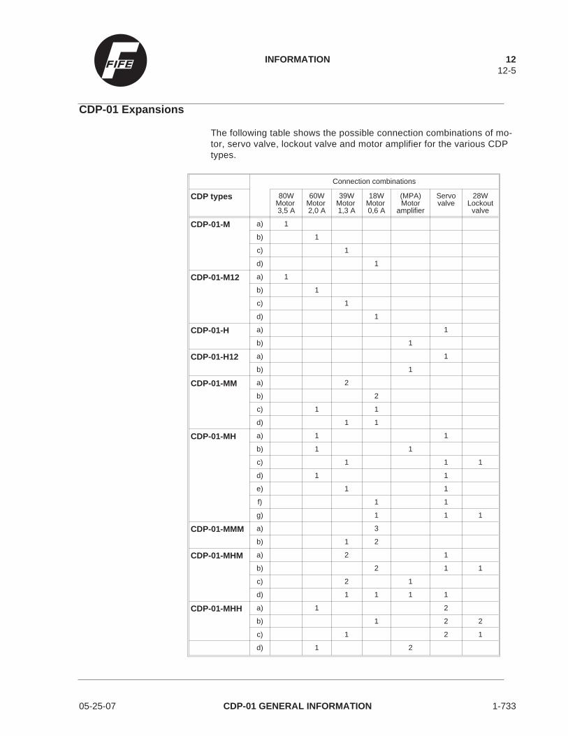
CDP-01 Expansions
The following table shows the possible connection combinations of mo-tor, servo valve, lockout valve and motor amplifier for the various CDPtypes.
Connection combinations
CDP types 80WMotor3,5 A
60WMotor2,0 A
39WMotor1,3 A
18WMotor0,6 A
(MPA)Motor
amplifier
Servovalve
28WLockout
valve
CDP-01-M a) 1
b) 1
c) 1
d) 1
CDP-01-M12 a) 1
b) 1
c) 1
d) 1
CDP-01-H a) 1
b) 1
CDP-01-H12 a) 1
b) 1
CDP-01-MM a) 2
b) 2
c) 1 1
d) 1 1
CDP-01-MH a) 1 1
b) 1 1
c) 1 1 1
d) 1 1
e) 1 1
f) 1 1
g) 1 1 1
CDP-01-MMM a) 3
b) 1 2
CDP-01-MHM a) 2 1
b) 2 1 1
c) 2 1
d) 1 1 1 1
CDP-01-MHH a) 1 2
b) 1 2 2
c) 1 2 1
d) 1 2
INFORMATION 1212-5
05-25-07 CDP-01 GENERAL INFORMATION 1-733

Accessories
Hydraulic Servo Valve
Information on request.
External Input Devices
RGPC-20, RGPC-21The sensor guide point can be shifted more easily with the external in-put device RGPC-20 or RGPC-21.
RCAL-20, RCAL-21The sensor calibration can be adjusted more easily with the external in-put device RCAL-20 or RCAL-21.
Ordering
NoteFor each spare parts order the part numbers, drawing numbers andtype designation of the signal amplifier must be quoted. They are foundon the enclosure underneath the line connection socket, or on the side.
Service
When you need parts and service, please contact one of the followingaddresses. Keep the enclosed documents in a safe place so that wecan assist you quickly and easily when you need service.
FIFE CorporationPost Office Box 26508Oklahoma City, OK 73126, USATelephone: (405) 755-1600FAX: (405) 755-8425
FIFE Japan Ltd.328-1 Sanno-choChiba City, Chiba 281, JapanTelephone: (0434) 21-1622Telex: 3722532FAX: (0434) 21-2895
FIFE GmbHD-65762 Kelkheim,Postfach 1240, GermanyD-65779 Kelkheim,Fifestr. 1, GermanyTelephon: (06195) 7002-0Telex: 4072321FAX: (06195) 3018
12 INFORMATION12-6
1-733 CDP-01 GENERAL INFORMATION 05-25-07