field of armor - machinegun · 2017-07-06 · page 1 field of armor sdkfz-251/c instructions 1/6...
TRANSCRIPT
Page 1
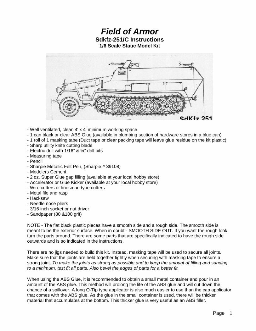
Field of Armor Sdkfz-251/C Instructions
1/6 Scale Static Model Kit
- Well ventilated, clean 4' x 4' minimum working space - 1 can black or clear ABS Glue (available in plumbing section of hardware stores in a blue can) - 1 roll of 1 masking tape (Duct tape or clear packing tape will leave glue residue on the kit plastic) - Sharp utility knife cutting blade - Electric drill with 1/16” & ¼” drill bits - Measuring tape - Pencil - Sharpie Metallic Felt Pen, (Sharpie # 39108) - Modelers Cement - 2 oz. Super Glue gap filling (available at your local hobby store) - Accelerator or Glue Kicker (available at your local hobby store) - Wire cutters or linesman type cutters - Metal file and rasp - Hacksaw - Needle nose pliers - 3/16 inch socket or nut driver - Sandpaper (80 &100 grit)
NOTE - The flat black plastic pieces have a smooth side and a rough side. The smooth side is meant to be the exterior surface. When in doubt - SMOOTH SIDE OUT. If you want the rough look, turn the parts around. There are some parts that are specifically indicated to have the rough side outwards and is so indicated in the instructions.
There are no jigs needed to build this kit. Instead, masking tape will be used to secure all joints. Make sure that the joints are held together tightly when securing with masking tape to ensure a strong joint. To make the joints as strong as possible and to keep the amount of filling and sanding to a minimum, test fit all parts. Also bevel the edges of parts for a better fit.
When using the ABS Glue, it is recommended to obtain a small metal container and pour in an amount of the ABS glue. This method will prolong the life of the ABS glue and will cut down the chance of a spillover. A long Q-Tip type applicator is also much easier to use than the cap applicator that comes with the ABS glue. As the glue in the small container is used, there will be thicker material that accumulates at the bottom. This thicker glue is very useful as an ABS filler.

Page 2
Super Glue, Modelers Cement and ABS Glue can be sanded easily when cured. If your glue joints aren't as clean as you would like them, let the glue fully cure then sand and fill as necessary. INJECTION PARTS:
ACCESSORY TREE FENDER TREE
SUSPENSION TREE SPROCKET TREE WITH ARMS

Page 3
WHEEL BAG WITH ARMS TRACK BAGS
TIRE HUB TREE PARTS SHEETS
HARDWARE WIRE RODS AND PLASTIC TUBE Plastic Parts Identification: Refer to the flat plastic parts diagrams located at the end of the instructions. Use these diagrams to locate the various parts. It is very useful to transfer the parts numbers from the diagrams to the actual parts. Use the metallic sharpie to write the part numbers on the parts. The Sharpie numbers can later be removed using “Oops”, a multipurpose cleaner and remover, available at most hardware stores.
The Sharpie marker can also be used to mark the various injection parts.
Page 4
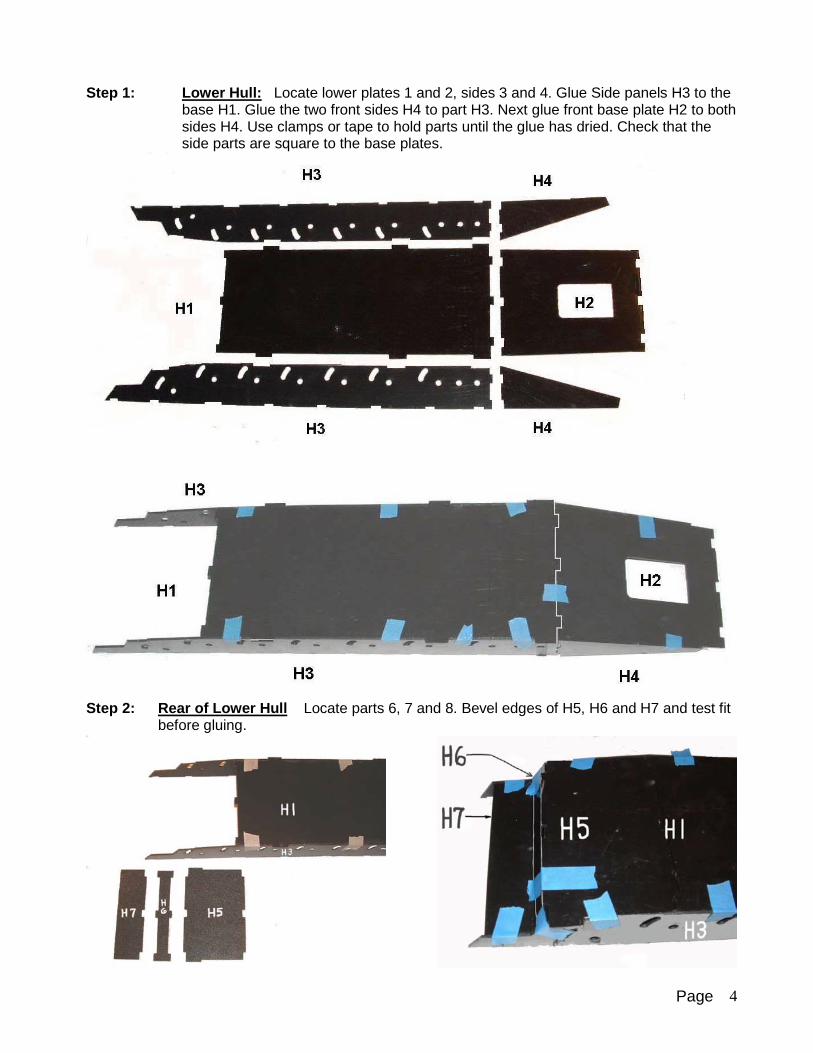
Step 1: Lower Hull: Locate lower plates 1 and 2, sides 3 and 4. Glue Side panels H3 to the base H1. Glue the two front sides H4 to part H3. Next glue front base plate H2 to both sides H4. Use clamps or tape to hold parts until the glue has dried. Check that the side parts are square to the base plates.
Step 2: Rear of Lower Hull Locate parts 6, 7 and 8. Bevel edges of H5, H6 and H7 and test fit
before gluing.

Page 5
Step 3: Upright Support: Locate parts 8 and 9. Dry fit to lower hull. Upright 8 is to be located at the joint between side panels 3 and 4, which is shown in the next step. Upright 9 is to be located at the end of panel H1. Tack glue H9 in place. This part is used as a stiffener and a temporary frame during construction and is to be removed after the hull is framed and glued in place.
Step 4: Side Panels: Side parts 11, 12 and 13 to be glued to the lower hull.
Step 5: Side Panel Installation: Attach panels H-12 to the top of parts H-10, using the uprights
to set the proper angle and spacing. Use masking tape to hold the panels in place while
Page 6
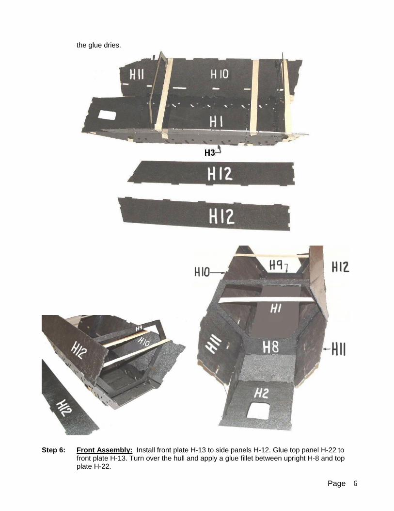
the glue dries.
Step 6: Front Assembly: Install front plate H-13 to side panels H-12. Glue top panel H-22 to
front plate H-13. Turn over the hull and apply a glue fillet between upright H-8 and top plate H-22.
Page 7
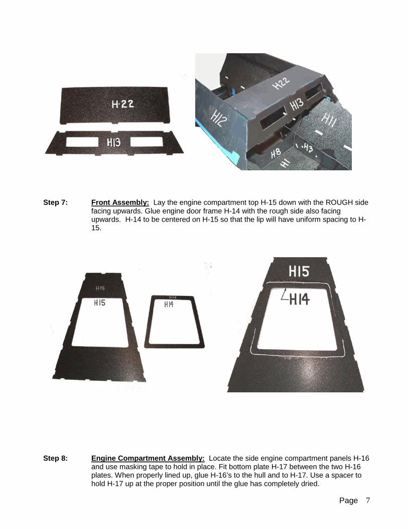
Step 7: Front Assembly: Lay the engine compartment top H-15 down with the ROUGH side
facing upwards. Glue engine door frame H-14 with the rough side also facing upwards. H-14 to be centered on H-15 so that the lip will have uniform spacing to H-15.
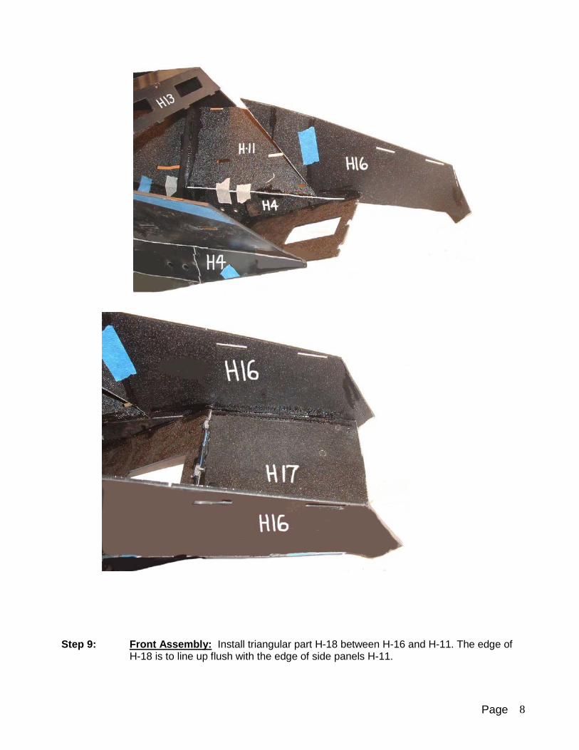
Step 8: Engine Compartment Assembly: Locate the side engine compartment panels H-16
and use masking tape to hold in place. Fit bottom plate H-17 between the two H-16 plates. When properly lined up, glue H-16’s to the hull and to H-17. Use a spacer to hold H-17 up at the proper position until the glue has completely dried.
Page 8
Step 9: Front Assembly: Install triangular part H-18 between H-16 and H-11. The edge of
H-18 is to line up flush with the edge of side panels H-11.
Page 9
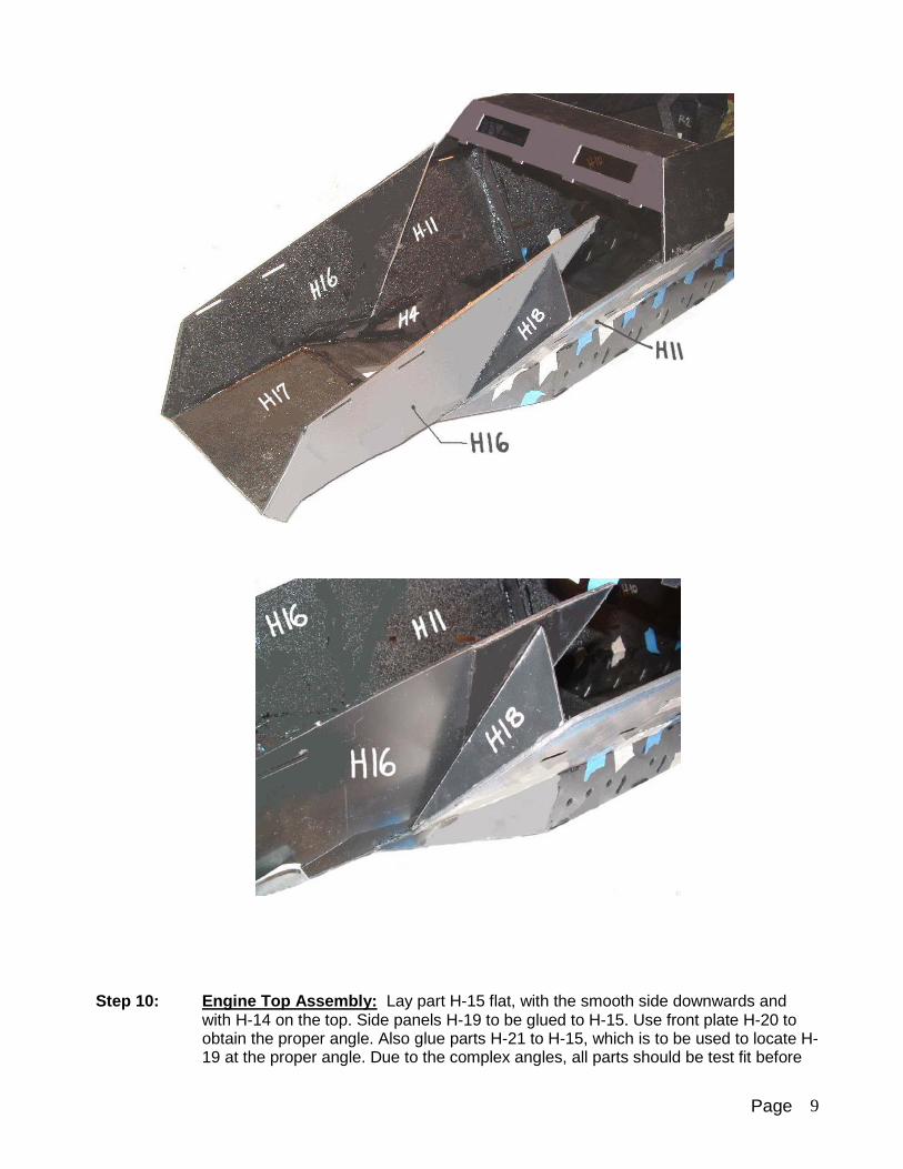
Step 10: Engine Top Assembly: Lay part H-15 flat, with the smooth side downwards and
with H-14 on the top. Side panels H-19 to be glued to H-15. Use front plate H-20 to obtain the proper angle. Also glue parts H-21 to H-15, which is to be used to locate H-19 at the proper angle. Due to the complex angles, all parts should be test fit before
Page 10
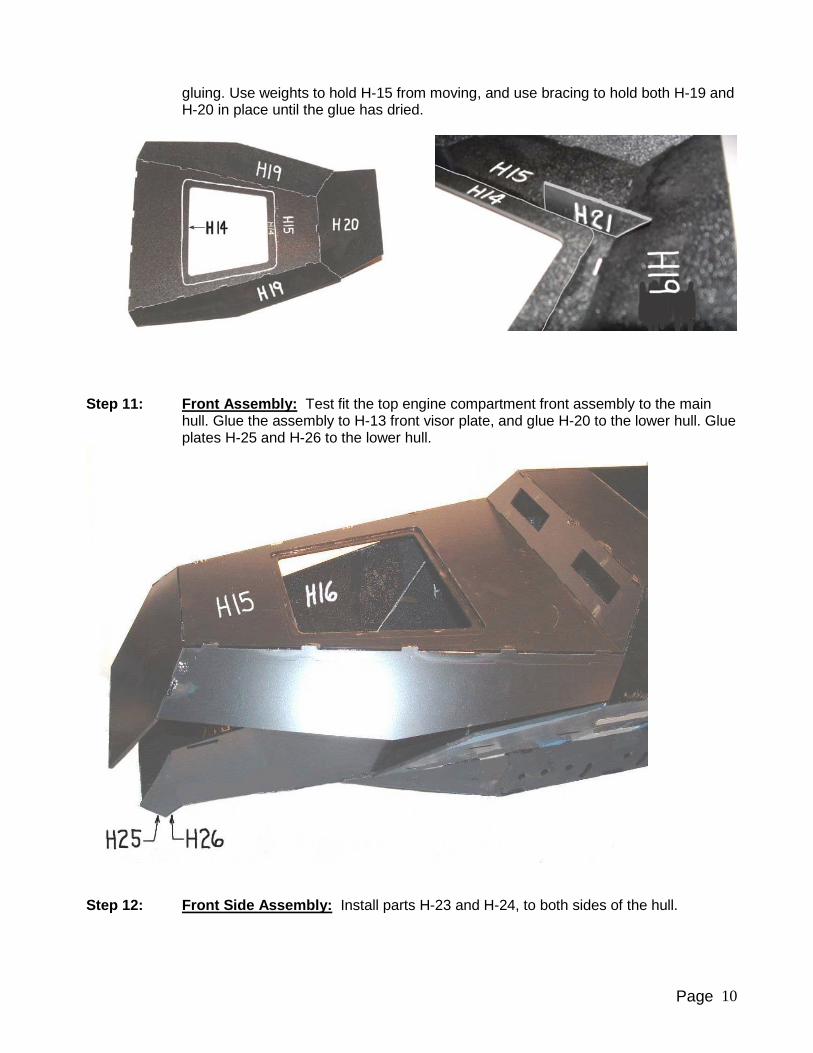
gluing. Use weights to hold H-15 from moving, and use bracing to hold both H-19 and H-20 in place until the glue has dried.
Step 11: Front Assembly: Test fit the top engine compartment front assembly to the main
hull. Glue the assembly to H-13 front visor plate, and glue H-20 to the lower hull. Glue plates H-25 and H-26 to the lower hull.
Step 12: Front Side Assembly: Install parts H-23 and H-24, to both sides of the hull.

Page 11
Step 13: Base Stiffener: Install H-27 to each side of upright H-8. The top of parts H-27 to be
1/8” below the top edge of upright H-8. This is critical, since the floor plate is to be mounted on top of H-27 and be level with the top edge of H-8. Use a scrap piece of 1/8” thick plastic to obtain the proper spacing of parts H-27.
Step 14: Dashboard Backplate: Install dashboard backplate H-28. Glue to the surrounding
hull parts.

Page 12
Step 15: Front Canvas Hold down: Glue the two H-30 plates together. Glue H-31 to the top
of the two H-30 plates. When dry, position and glue to top plate H-22.
Step 16: Rear Hull: Install parts R-2 and R-4 by taping to the main hull. Use a rasp or file to
the edges of the parts so that they will have more surface area to glue. Tape in place parts R-1 and R-3. After all parts are lined up, apply glue to the inside joints. Apply
Page 13
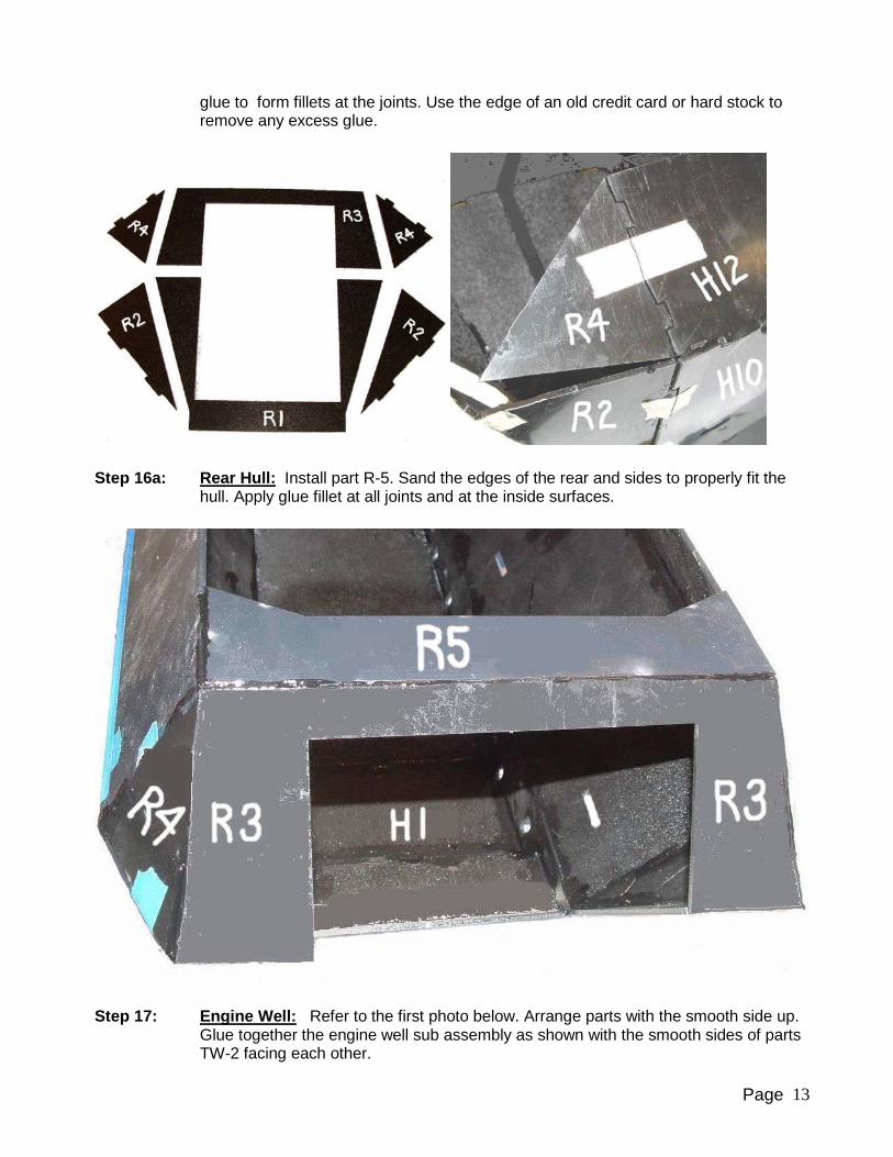
glue to form fillets at the joints. Use the edge of an old credit card or hard stock to remove any excess glue.
Step 16a: Rear Hull: Install part R-5. Sand the edges of the rear and sides to properly fit the
hull. Apply glue fillet at all joints and at the inside surfaces.
Step 17: Engine Well: Refer to the first photo below. Arrange parts with the smooth side up.
Glue together the engine well sub assembly as shown with the smooth sides of parts TW-2 facing each other.

Page 14
Step 17a: Engine Well Installation: Install the engine well sub assembly to the inside of the
hull, and over the hole in part H-2. Note that part of the main hull is not shown for clarity.
Step 18: Engine Oil Pan: Glue together the engine oil pan parts as shown, The smooth side
of all parts to face outwards. Bevel edges for better fit. Stack and glue together the two TH-1 plates, and center the engine pan on the top of TH-1.

Page 15
Step 19: Engine Oil Pan: The first photo shows the engine pan assembly mounted inside of
the engine well. The lower hull is not shown for clarity. The second photo shows the engine oil pan, located in the engine well and protruding down from part H-2.
Step 20: Engine Vents: Glue together the engine vents with the smooth side outwards. Make
a left and a right hand unit. When dry, glue the engine vents to the main hull, and centered on the engine door openings.

Page 16
Step 21: Internal Storage Bins: Glue a B-3 to each end of B-1. Install B-3 parts with the
smooth sides facing outwards. The third B-3 should be glued at 5.75” from one end. Note that this is not the midpoint of B-1. Make a right and a left hand unit. The storage bins are to be installed inside the hull with the middle B-3 brace favoring the rear of the vehicle. Install bottom plate B-2 to B-1 and to the B-3 parts.
Use tape and mark 1.75” length. Install the interior storage bin at 1.75” from the edge of part R-2. Note that the storage bins need to be installed with the middle B-3 brace towards the rear of the hull.

Page 17
Step 22: Front Fenders: Arrange the parts as shown, for a left and a right hand assembly. Smooth side of plastic to face upwards. Use tape to hold the parts together while the glue dries. Refer to the Fender Tree with numbered parts, at the end of the instructions.
Glue the front fenders to each side of the hull.
Step 23: Rear Fenders: Arrange the fender parts as shown. Make a left and a right hand
fender. Smooth side of the plastic is to face upwards. Glue injection fender edge part

Page 18
G to F-3 and to E. When G is securely glued in place, install fender piece F-5. Bend G to line up with F-5 and tape until the glue has dried.
Step 24: Droop Fender Section: Glue fender piece F-6 as shown on the right side of the hull.
F-7 is for the left side of the hull. Install injection fender piece F to the left and right side of the hull.
Page 19
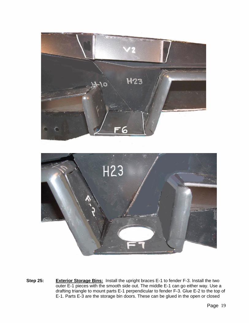
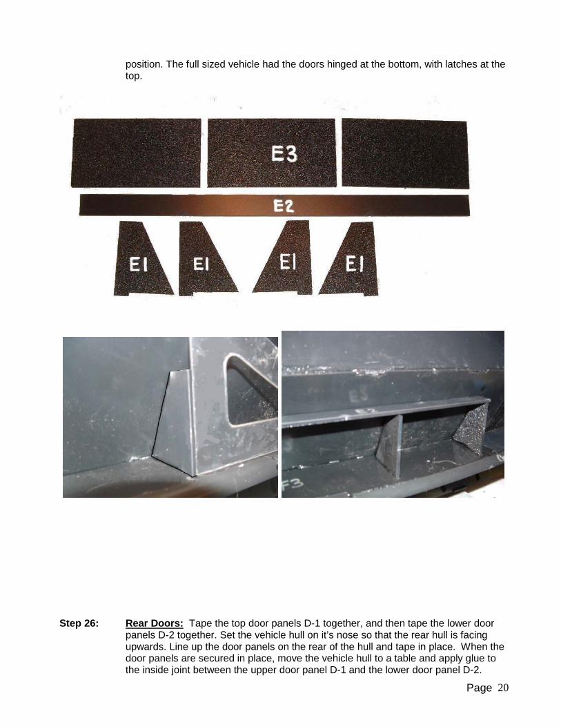
Step 25: Exterior Storage Bins: Install the upright braces E-1 to fender F-3. Install the two
outer E-1 pieces with the smooth side out. The middle E-1 can go either way. Use a drafting triangle to mount parts E-1 perpendicular to fender F-3. Glue E-2 to the top of E-1. Parts E-3 are the storage bin doors. These can be glued in the open or closed
Page 20
position. The full sized vehicle had the doors hinged at the bottom, with latches at the top.
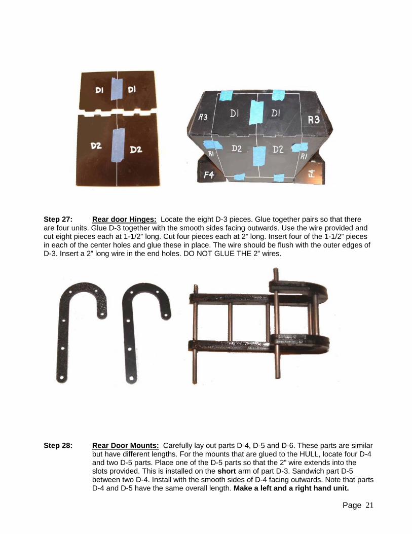
Step 26: Rear Doors: Tape the top door panels D-1 together, and then tape the lower door
panels D-2 together. Set the vehicle hull on it’s nose so that the rear hull is facing upwards. Line up the door panels on the rear of the hull and tape in place. When the door panels are secured in place, move the vehicle hull to a table and apply glue to the inside joint between the upper door panel D-1 and the lower door panel D-2.
Page 21
Step 27: Rear door Hinges: Locate the eight D-3 pieces. Glue together pairs so that there are four units. Glue D-3 together with the smooth sides facing outwards. Use the wire provided and cut eight pieces each at 1-1/2” long. Cut four pieces each at 2” long. Insert four of the 1-1/2” pieces in each of the center holes and glue these in place. The wire should be flush with the outer edges of D-3. Insert a 2” long wire in the end holes. DO NOT GLUE THE 2” wires.
Step 28: Rear Door Mounts: Carefully lay out parts D-4, D-5 and D-6. These parts are similar
but have different lengths. For the mounts that are glued to the HULL, locate four D-4 and two D-5 parts. Place one of the D-5 parts so that the 2” wire extends into the slots provided. This is installed on the short arm of part D-3. Sandwich part D-5 between two D-4. Install with the smooth sides of D-4 facing outwards. Note that parts D-4 and D-5 have the same overall length. Make a left and a right hand unit.
Page 22
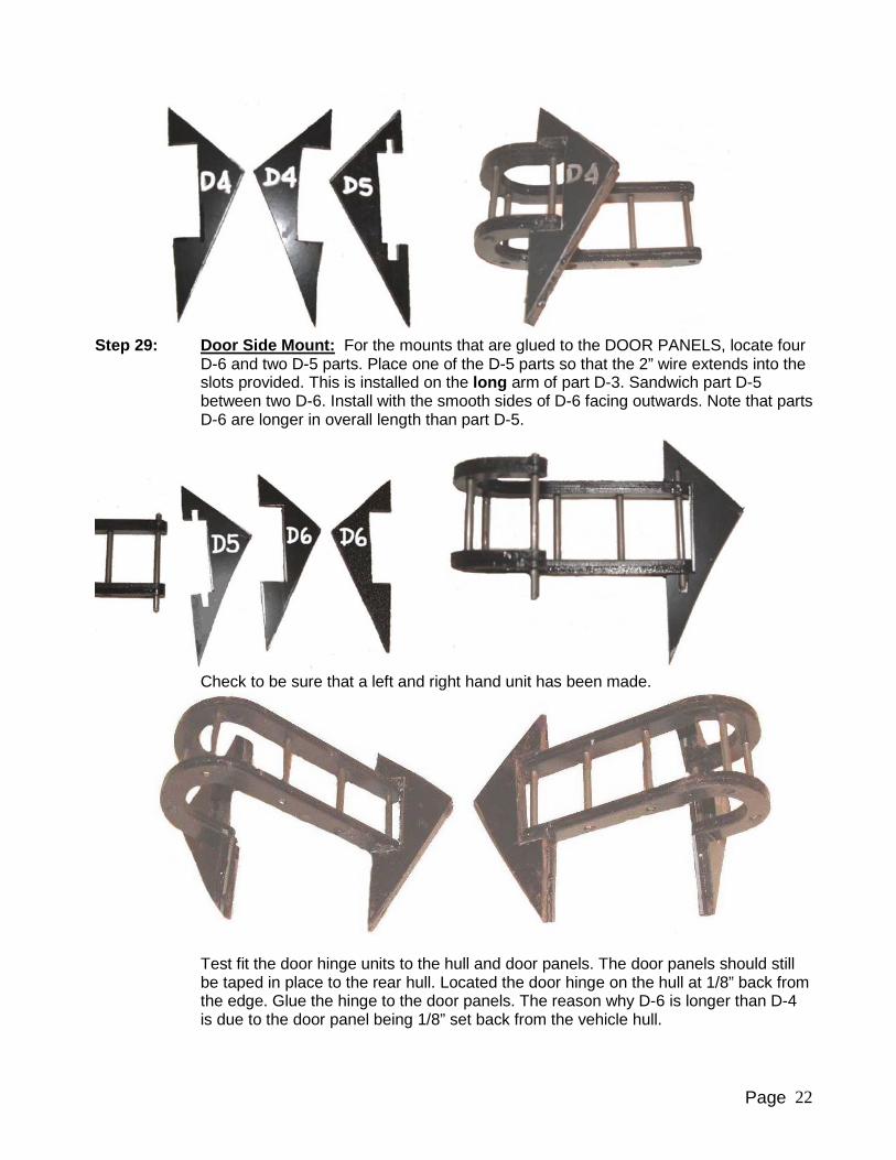
Step 29: Door Side Mount: For the mounts that are glued to the DOOR PANELS, locate four
D-6 and two D-5 parts. Place one of the D-5 parts so that the 2” wire extends into the slots provided. This is installed on the long arm of part D-3. Sandwich part D-5 between two D-6. Install with the smooth sides of D-6 facing outwards. Note that parts D-6 are longer in overall length than part D-5.
Check to be sure that a left and right hand unit has been made.
Test fit the door hinge units to the hull and door panels. The door panels should still be taped in place to the rear hull. Located the door hinge on the hull at 1/8” back from the edge. Glue the hinge to the door panels. The reason why D-6 is longer than D-4 is due to the door panel being 1/8” set back from the vehicle hull.

Page 23
Step 30: Gear Mount: Glue G-1 to each side of the injection plastic leaf spring. Smooth side
of G-1 to face outwards. Make sure that G-1 parts are lined up by inserting the mounting bolt.
Step 31: Hull Gear Mounting Block: Glue together the four G-2 parts together. Use the
mounting bolt to make sure that the holes are lined up. Install the G-2 assembly on the inside of the vehicle hull H-5. With the bolt hole protruding down through the bottom of the hull.

Page 24
Step 32: Gear Mount: Test fit the gear mount by lining up the holes in G1 and G-2. The G-2
parts fit between parts G-1.
Step 33: Front Axle Frame: Fit the arms to each side of the axle frame. Glue the top retaining
arm to the frame, which will hold the arms in place. Do not apply any glue to the tire arms.
Step 34: Arm Connecting Rod: Install the connecting arm to the two tire arms. Glue the pins
in pace, making sure not to get glue on the connecting arm.
Page 25
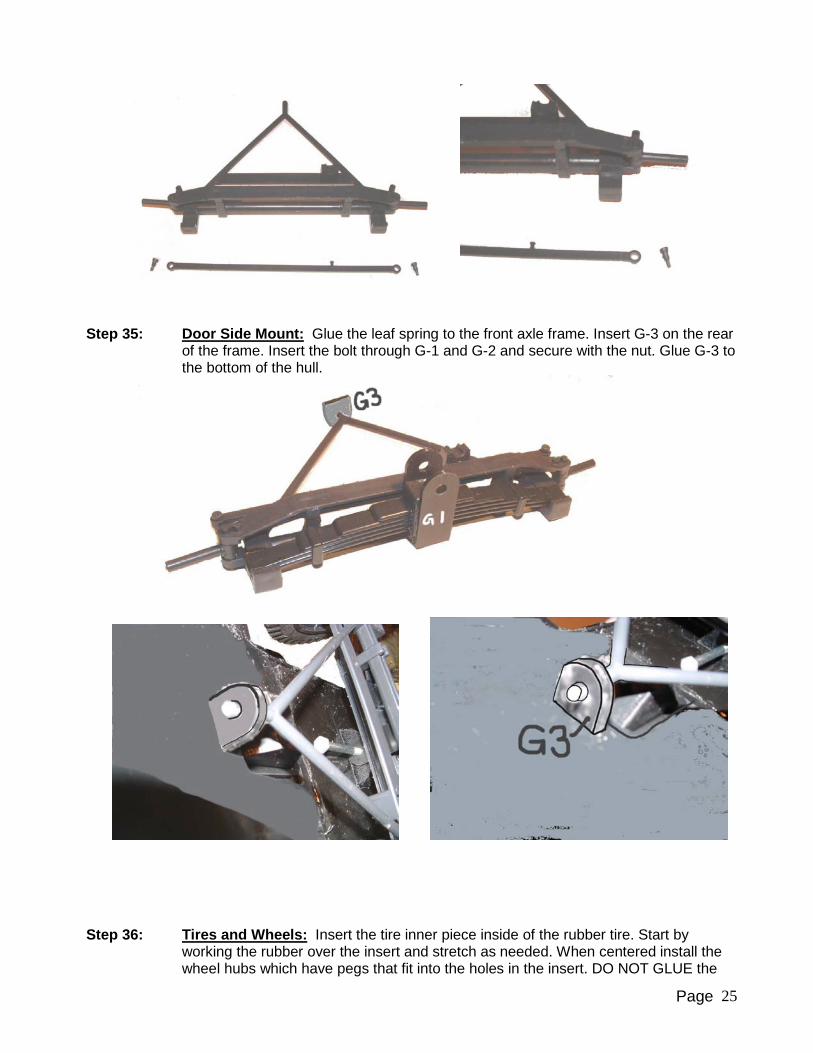
Step 35: Door Side Mount: Glue the leaf spring to the front axle frame. Insert G-3 on the rear
of the frame. Insert the bolt through G-1 and G-2 and secure with the nut. Glue G-3 to the bottom of the hull.
Step 36: Tires and Wheels: Insert the tire inner piece inside of the rubber tire. Start by
working the rubber over the insert and stretch as needed. When centered install the wheel hubs which have pegs that fit into the holes in the insert. DO NOT GLUE the
Page 26
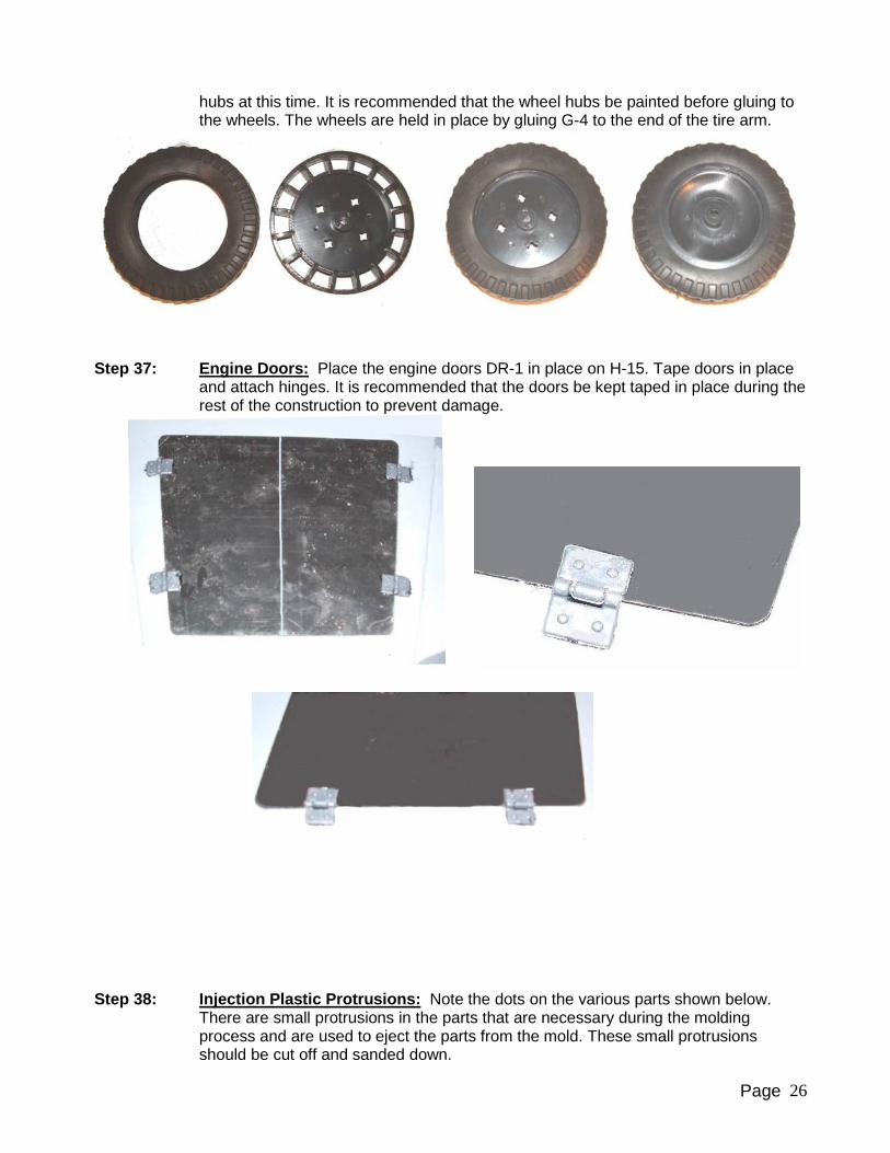
hubs at this time. It is recommended that the wheel hubs be painted before gluing to the wheels. The wheels are held in place by gluing G-4 to the end of the tire arm.
Step 37: Engine Doors: Place the engine doors DR-1 in place on H-15. Tape doors in place
and attach hinges. It is recommended that the doors be kept taped in place during the rest of the construction to prevent damage.
Step 38: Injection Plastic Protrusions: Note the dots on the various parts shown below.
There are small protrusions in the parts that are necessary during the molding process and are used to eject the parts from the mold. These small protrusions should be cut off and sanded down.

Page 27
Step 39: Mounting Bolts: The hardware shown below is used for mounting of the running
gear. The short bolts are used to mount the swing arms to the hull. The two medium, black bolts are for the drive sprockets. The long bolts are for mounting the road wheels to the swing arms.
Step 40: Six Hole Road Wheels: The swing arms need to have the hole drilled and tapped
for the hull mounting bolts. Assemble the six hole road wheel units as shown. There will be eight such assemblies.

Page 28
Step 41: Eight Hole Road Wheels: The swing arms need to have the hole drilled and tapped
for the hull mounting bolts. Assemble the eight hole road wheel units as shown. There will be six such assemblies.
Step 42: Drive Sprockets: The swing arms need to have the hole drilled and tapped for the
hull mounting bolts. Cut the rollers from the tree and clean off any flashing. The rollers will fit onto the roller axles. Note that the holes in the rollers are tapered so that they will slide on to the axles in only one direction. Attach the two drive sprocket
Page 29
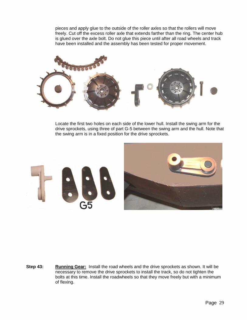
pieces and apply glue to the outside of the roller axles so that the rollers will move freely. Cut off the excess roller axle that extends farther than the ring. The center hub is glued over the axle bolt. Do not glue this piece until after all road wheels and track have been installed and the assembly has been tested for proper movement.
Locate the first two holes on each side of the lower hull. Install the swing arm for the drive sprockets, using three of part G-5 between the swing arm and the hull. Note that the swing arm is in a fixed position for the drive sprockets.
Step 43: Running Gear: Install the road wheels and the drive sprockets as shown. It will be
necessary to remove the drive sprockets to install the track, so do not tighten the bolts at this time. Install the roadwheels so that they move freely but with a minimum of flexing.
Page 30
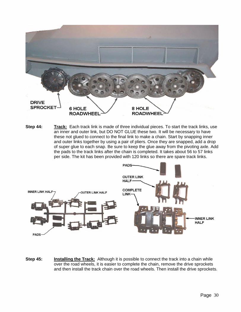
Step 44: Track: Each track link is made of three individual pieces. To start the track links, use
an inner and outer link, but DO NOT GLUE these two. It will be necessary to have these not glued to connect to the final link to make a chain. Start by snapping inner and outer links together by using a pair of pliers. Once they are snapped, add a drop of super glue to each snap. Be sure to keep the glue away from the pivoting axle. Add the pads to the track links after the chain is completed. It takes about 56 to 57 links per side. The kit has been provided with 120 links so there are spare track links.
Step 45: Installing the Track: Although it is possible to connect the track into a chain while over the road wheels, it is easier to complete the chain, remove the drive sprockets and then install the track chain over the road wheels. Then install the drive sprockets.

Page 31
Step 46: Towing Hooks: Glue together the tow hooks, two per side. Then glue to H-16 on
each side of H-20.
Step 47: Headlights: Glue the lens plate to the headlight housing. Glue mounts H-34 to the
bottom of the front fenders. A piece of scrap plastic can be used to fill the ear gap between the fender and H-34. Review the documentation of the Sdkfz-251 that is being modeled. The actual headlight mounting location varied from near the hull, to farther out on the fender. Additionally, some variants did not have part H-34 and had the headlight mounted directly to the top of the fender. For this installation, it will be necessary to drill a hole through the fender.
Step 48: Visors: The long visors are mounted to the front of the hull. The shorter visors are
mounted on the side of the hull. The four small angular pieces are mounted to the front visors and are used if the visors are to be glued in the open position. Two pieces per visor.
Page 32
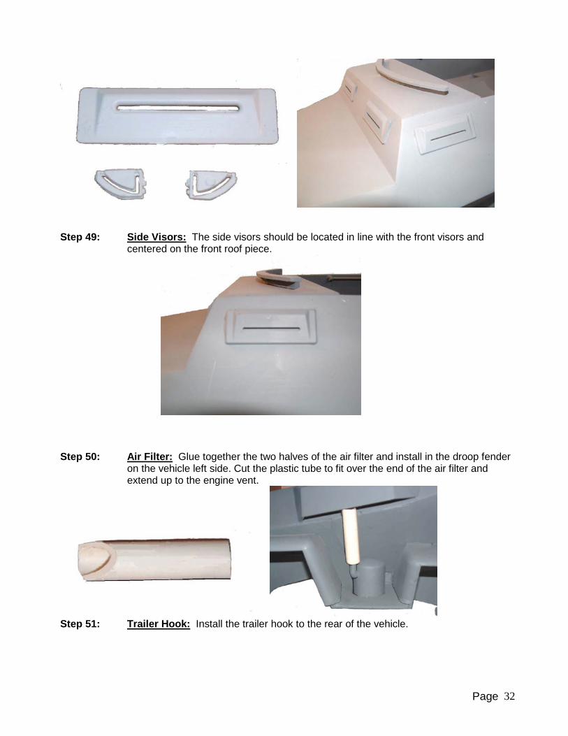
Step 49: Side Visors: The side visors should be located in line with the front visors and
centered on the front roof piece.
Step 50: Air Filter: Glue together the two halves of the air filter and install in the droop fender
on the vehicle left side. Cut the plastic tube to fit over the end of the air filter and extend up to the engine vent.
Step 51: Trailer Hook: Install the trailer hook to the rear of the vehicle.

Page 33
Step 52: Hand Rails: Use two of the 12” metal rods Slide on four of had rail stand-offs HR-1
on each rod. Part HR-1 will fit into the slots in the upper hull plate H-12. Install parts HR-1 so they are flush with the outside of plate H-12. Fit into place and then use superglue.
Step 53: Front Seats: Glue the seat base as shown, using S-1, 3, 4 and 5. When the glue
has dried, position seat back S-2 between parts S-5. Insert a wire rod through the holes in S-5 and glue to the back of S-2. When dry, the seat back is able to fold down to allow easier access to install a 12” figure. Make two seats.
Page 34
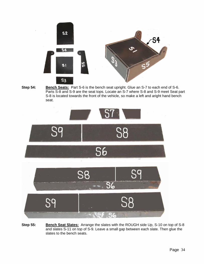
Step 54: Bench Seats: Part S-6 is the bench seat upright. Glue an S-7 to each end of S-6.
Parts S-8 and S-9 are the seat tops. Locate an S-7 where S-8 and S-9 meet Seat part S-8 is located towards the front of the vehicle, so make a left and aright hand bench seat.
Step 55: Bench Seat Slates: Arrange the slates with the ROUGH side Up, S-10 on top of S-8
and slates S-11 on top of S-9. Leave a small gap between each slate. Then glue the slates to the bench seats.
Page 35
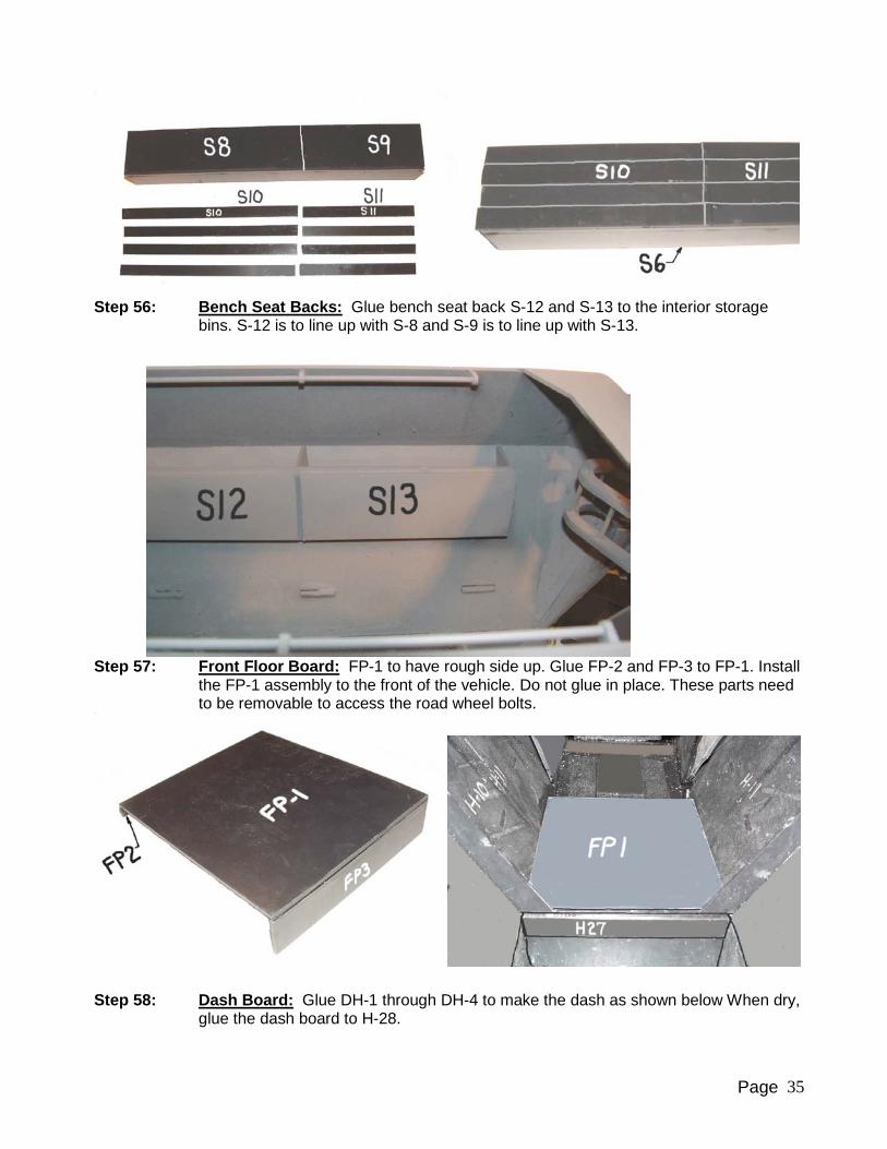
Step 56: Bench Seat Backs: Glue bench seat back S-12 and S-13 to the interior storage
bins. S-12 is to line up with S-8 and S-9 is to line up with S-13.
Step 57: Front Floor Board: FP-1 to have rough side up. Glue FP-2 and FP-3 to FP-1. Install
the FP-1 assembly to the front of the vehicle. Do not glue in place. These parts need to be removable to access the road wheel bolts.
Step 58: Dash Board: Glue DH-1 through DH-4 to make the dash as shown below When dry,
glue the dash board to H-28.

Page 36
Step 59: Mounting Front Seats: Glue the front seats to floor plate FP-1.
Step 60: Mounting Bench Seats: Glue the doubler 17 to the inside of the hull.
Step 61: Steering Wheel: Glue the two DH-7 and DH-8 parts together, with the slots in the
center. Cut a half inch length of wire and glue into the slot. Glue the steering wheel to

Page 37
the wire. The second photo shows the orientation for installation of the steering wheel to the dash board. The steering wheel does angle downwards from the driver.
Step 62: Radiator Caps: Bevel and round the top edges of parts H-36. Glue the radiator and
drain caps as shown to the front of the vehicle.
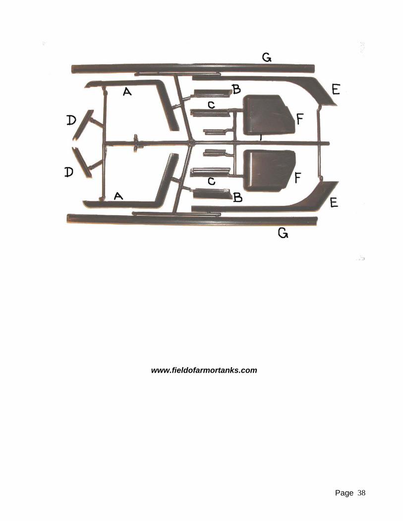
Fender Tree Key Numbers:
Page 38
www.fieldofarmortanks.com