fiber optic modem installation instructions - anz region · iv read and save these instructions....
TRANSCRIPT

Fiber Optic Modem Installation Instructions
579-831 Rev. H


©2006-2011 SimplexGrinnell LP. All rights reserved.
Specifications and other information shown were current as of publication and are subject to change without notice.
Simplex and the Simplex logo are trademarks of Tyco International Ltd. and its affiliates and are used under license.
All other logos and product names are trademarks or registered trademarks of their respective companies.
Copyright and Trademarks
Copyright
Trademarks

iv
READ AND SAVE THESE INSTRUCTIONS. Follow the instructions in this installation manual. These instructions must be followed to avoid damage to this product and associated equipment. Product operation and reliability depend upon proper installation. DO NOT INSTALL ANY SIMPLEX® PRODUCT THAT APPEARS DAMAGED. Upon unpacking your Simplex product, inspect the contents of the carton for shipping damage. If damage is apparent, immediately file a claim with the carrier and notify an authorized Simplex product supplier. ELECTRICAL HAZARD - Disconnect electrical field power when making any internal adjustments or repairs. All repairs should be performed by a representative or authorized agent of your local Simplex product supplier. STATIC HAZARD - Static electricity can damage components. Handle as follows: • Ground yourself before opening or installing components. • Prior to installation, keep components wrapped in anti-static material at all times. EYE SAFETY HAZARD - Under certain fiber optic application conditions, the optical output of this device may exceed eye safety limits. Do not use magnification (such as a microscope or other focusing equipment) when viewing the output of this device. FCC RULES AND REGULATIONS – PART 15 - This equipment has been tested and found to comply with the limits for a Class A digital device, pursuant to part 15 of the FCC Rules. These limits are designed to provide reasonable protection against harmful interference when the equipment is operated in a commercial environment. This equipment generates, uses, and can radiate radio frequency energy and, if not installed and used in accordance with the instruction manual, may cause harmful interference to radio communications. Operation of this equipment in a residential area is likely to cause harmful interference in which case the user will be required to correct the interference at his own expense. SYSTEM REACCEPTANCE TEST AFTER SOFTWARE CHANGES - To ensure proper system operation, this product must be tested in accordance with NFPA 72® after any programming operation or change in site-specific software. Reacceptance testing is required after any change, addition or deletion of system components, or after any modification, repair or adjustment to system hardware or wiring. All components, circuits, system operations, or software functions, known to be affected by a change, must be 100% tested. In addition, to ensure that other operations are not inadvertently affected, at least 10% of initiating devices that are not directly affected by the change, up to a maximum of 50 devices, must also be tested and proper system operation verified. NFPA 72® is a registered trademark of the National Fire Protection Association.
Cautions and Warnings

v
Introduction to the Fiber Optic Modem ........................................................... 1 General Overview ........................................................................................ 1 Definitions and Terms .................................................................................. 1 Digital Audio Riser Overview ..................................................................... 2 Analog Audio Riser Overview ..................................................................... 2 4120 Network Overview .............................................................................. 2 RUI Overview .............................................................................................. 2 Fiber Modem Audio Expansion Board ........................................................ 2 Illustration .................................................................................................... 3 PID List ........................................................................................................ 4 Specifications ............................................................................................... 4
Modem Configuration ...................................................................................... 6 Supported Configurations ............................................................................ 6 SW1 (RUI/4120 Network) Configuration Settings ...................................... 6 SW2 (Digital Audio Riser, Enhanced Analog Audio, and Standard Analog Audio Channel 1) Configuration Settings ....................................... 7 SW3 (Analog Audio Channel 2) Configuration Settings ............................. 8 SW4 (Fiber Modem Audio Expansion Board) Configuration Settings ........ 8 4120 Network Wiring, Analog Audio, and RUI Jumper Placements .......... 9
Fiber Modem Audio Expansion Board .......................................................... 10 Description ................................................................................................. 10 Jumper Configuration ................................................................................ 10
Mounting ........................................................................................................ 11 Mounting Instructions ................................................................................ 11
Wiring ............................................................................................................ 14 Overview .................................................................................................... 14 Fiber Connection ........................................................................................ 14 4120 Network Wiring Specifications ......................................................... 15 Analog Audio Riser Wiring Specifications ................................................ 17 Enhanced Analog Audio (EAA) Riser Wiring Specifications ................... 19 Digital Audio Riser Specifications ............................................................. 21 RUI Wiring Specifications ......................................................................... 22 Fiber Modem Audio Expansion Board Wiring Specifications ................... 24
Connecting Power to the Modem ................................................................... 25 Where to Connect Power ........................................................................... 25
Testing and Troubleshooting ......................................................................... 27 General ....................................................................................................... 27 LED Indications ......................................................................................... 28 Fiber Fault LED ......................................................................................... 28 Digital Audio Riser (DAR) ........................................................................ 28 Analog Audio ............................................................................................. 29 4120 Network ............................................................................................ 29 RUI ............................................................................................................ 29 System Checkout ....................................................................................... 29 Testing Circuit Supervision ....................................................................... 30
Appendix – Sample Configurations ............................................................... 31 Overview .................................................................................................... 31 Internal Building or Multi-Building Configuration – Class A/Style 7 or Style 6 .................................................................................................... 31 RUI (excluding 4120 Network) Class A/Style 7 ........................................ 32 4120 Network (excluding RUI) Class A/Style 7 ........................................ 33 Analog Audio Class A/Style 6 ................................................................... 34 Enhanced Analog Audio (EAA) (limited to Channel 1 & excluding Digital Audio) Class A/Style 6 .................................................................. 35 Digital Audio (excluding Analog Audio Channel 1) Class A/Style 7 ........ 36 Internal Building or Multi-Building Configuration – Class B/Style 4 ....... 37 RUI (Excluding 4120 Network) Class B/Style 4 ....................................... 38
Contents

vi
Analog Audio Class B/Style 4 .................................................................. 39 Enhanced Analog Audio (EAA) (limited to Channel 1 & excluding Digital Audio) Class B/Style 4 ................................................................... 40 Digital Audio (excluding Analog Audio Channel 1) Class B/Style 4 ........ 41 Hub Configuration Overview ..................................................................... 42 Hub Configuration – 4120 Network .......................................................... 43 Hub Configuration – Analog Audio ........................................................... 44 Hub Configuration – Digital Audio ........................................................... 45 Interconnected Loop and Star Configurations – Overview ........................ 46 Interconnected Loop and Star Configurations –4120 Network .................. 47 Interconnected Loop and Star Configurations – Analog Audio ................. 48 Interconnected Loop and Star Configurations – Digital Audio .................. 49 TrueSite Workstation (TSW) ..................................................................... 50 Fiber Modem Audio Expansion Board Class A/Style 6 ............................. 51 Fiber Modem Audio Expansion Board Class B/Style 4 ............................. 52

1
The Fiber Optic Modem is used to simplify field wiring and increase transmission distances by converting system copper-wired interfaces to fiber optic connections. It has field wiring connections for the Digital Audio Riser, Analog Audio Risers, RUI, and 4120 Network. A Modem pair replaces copper wiring between any two points including node-to-node, node-to-transponder, and transponder-to-transponder. The Modem is invisible to the connected equipment, and does not need to be programmed in as part of the job (except for power supply current calculations). The Modem combines the input signals so they can be communicated over one fiber in both directions. In general, the Modem installation is accomplished by simply connecting the wires that would normally be routed between cabinets to the Modem. The only additional steps required when using a Modem rather than copper are: 1) Configuring the DIP switches and jumpers according to the application. 2) Routing the “x-link” wire if the system has Class A Analog Audio or Class A RUI. Modems are always installed in pairs. There are four versions: a “right-port” and “left-port” version for each type of fiber; left and right for single-mode and a left and right for multimode. Any Modem link must consist of one of each type. The order in which Modem pairs are installed is arbitrary. A “left-to-right” Modem pair can be followed by another “left-to-right” pair, or by a “right-to-left” pair.
Enhanced Analog Audio (EAA): EAA refers to a reformatted version of the Analog Audio Riser that is wired between modems. In an EAA system, modems pass the Riser to the next modem as a digital signal via the DAR channel. EAA disallows the use of Analog Channel 2. Generic: A “Generic” modem is any modem that is not a Head-End or Tail-End modem. In a Class B configuration, all modems are generic. Head end: A “Head-End” modem is a modem with an electrical connection to the primary side of the head-end cabinet. If there are any fiber optic links between a modem and the head-end cabinet, then that modem is not a head-end modem. A modem with additional nodes or transponders between itself and the head-end cabinet, but no optical links, can still be a head-end modem. Local side: The “local side” of any configuration refers to all portions of the wiring loop that are electrically connected to the head-end cabinet. Any wiring that is isolated from the head end via one or more optical links is not electrically connected, and therefore considered “remote.” NIC: Network Interface Card. Remote side: The “remote side” of any configuration refers to all portions of the wiring loop that are not electrically connected to the head-end cabinet. Any system that is electrically connected to the head end (no optical links) is considered “local.” RIC: Riser Interface Card. Tail end: A “Tail-End” modem is a modem with an electrical connection to the secondary side (also known as a Class A return) of the head-end cabinet. If there are any fiber optic links between a modem and the head-end cabinet, then that modem is not considered a tail-end modem. A modem with additional nodes or transponders between itself and the head end, but no optical links, can still be a tail-end modem. X-link: The “x-link” is a pair of RUI or Analog Audio Riser wires that connect head-end and tail-end modems to one another. The link is required to maintain an electrical connection between the primary and secondary sides of the local-side wiring loop. (X-link definition is continued on the next page.)
Continued on next page
Introduction to the Fiber Optic Modem
General Overview
Definitions and Terms

2
X-link (continued): X-link connections are only required in Class A Analog Audio and Class A RUI configurations. They are not required for the Digital Audio Riser interface, a Network interface, or for any other Class B configuration. Where required, the x-link connection maintains Class A supervision even though the remote side of the fiber link is electrically isolated. The x-link is only wired between the two modems that are electrically connected to the head-end cabinet via RUI or riser wiring. (It is still considered electrically connected even if there are transponders between the modem and the head-end cabinet).
The Modem replaces copper wiring between a Digital Audio Controller and a Digital Audio Riser Interface Card, or between Digital Audio Riser Interface cards. Modem connections can be used between transponders, or between nodes in Network systems.
The Modem replaces copper wiring between an Analog Audio Controller and an Analog Audio Riser Interface Card, or between Analog Audio Riser Interface cards. Modem connections can be used between transponders, or between nodes in network systems. The Modem can be configured for 10 Vrms audio risers (standard), 1 V peak-to-peak audio risers, or 0.707 Vrms.
The standard analog audio usage of the fiber modem imposes a 6-modem-pair limit on system size. The Enhanced Analog Audio (EAA) feature removes this limitation by keeping a version of the analog stream digital through the wired link. Using EAA imposes other limitations, however, that include the following:
• Limitation to one analog channel only (Channel 1).
• Requires that the EAA wire (connected to DAR terminals) be close nippled (since it is unsupervised).
• Excludes the usage of the DAR interface for the Digital Audio Riser because the DAR interface is used as the EAA channel.
The Modem can replace either one or two wired connections between Network Interface Cards. It can replace the right-port wire, the left-port wire, or both. The Network Interface Cards that the Modem will connect to must have wired media cards installed. The Modem can be used to replace wiring between any two NICs, and it can also be used in lieu of a Physical Bridge. When the Modem is used in lieu of a Physical Bridge, the network topology appears as a typical ring configuration since the Modem effectively replaces two wires between the local and remote node. Refer to Figure A-18 that shows an Interconnected Loop without a Physical Bridge. The Interconnected Loop normally requires a Physical Bridge but doesn’t in this diagram because modems are used. Note that references to 4020, 4120, and 4100 Legacy Fire Alarm Panel systems are for retrofit applications only. None of these Fire Alarm System models have been listed to the Ninth Edition of UL864.
The Modem replaces copper wiring between a CPU Motherboard and Transponder Interface card, between Transponder Interface cards, or between a RUI card and Transponder Interface card. Maximum of eight pairs of Modems for RUI if wired Class A.
The Audio Expansion Board allows the Fiber Optic Modem to interface with 4100 Legacy Audio systems. The card has two channels, each of which are selectable for 70 Vrms or 25 Vrms risers. The card converts the 70 Vrms or 25 Vrms to a 10 Vrms signal to be used by the modem. The card connects to the modem via a ribbon harness.
Introduction to the Fiber Optic Modem, Continued
Definitions and Terms
Digital Audio Riser Overview
Analog Audio Riser Overview
4120 Network Overview
RUI Overview
Fiber Modem Audio Expansion Board

3
AUDIO RISERCHANNEL 2 LEVELSELECT
4120 NETWORKWIRE GAUGESELECT
EXPANSIONSWITCH
4120 NETWORK & RUIINTERFACE CONFIGURATION
DIGITAL AUDIO RISER ANDANALOG RISER CHANNEL 1CONFIGURATION
ANALOG RISER CHANNEL 2CONFIGURATION
FIBER OPTIC STCONNECTOR
24V POWERCONNECTIONOPTIONS
Fibertransceiver
EXPANSIONHEADER
TB2
P6 P5
P3
SW
1S
W2
SW
3
SW
4LED2
LED1
LED4
LED5
LED3
P7P8
P10
P9
P2
LED6LED8
LED10LED9LED7
TB1
RUI HEAD-ENDSELECT / X-LINKDISABLE
See Figure 1 (below) for important locations on the Modem board.
Figure 1. Fiber Optic Modem Board
Introduction to the Fiber Optic Modem, Continued
Illustration

4
This publication covers the following Product IDs (PIDs):
Table 1. Product IDs Covered by this Publication
Multimode Fiber Part Numbers PID Description Usage4100-6074 Fiber Optic Modem Left-Port Assembly 4100U/4100ES Bay Installation 4100-6075 Fiber Optic Modem Right-Port Assembly 4100U/4100ES Bay Installation
4190-9024 Fiber Optic Modem with Expansion Cabinet Assembly - Red Expansion to 4100ES, 4100U, 4100, 4010, 4010ES or 4020
4190-9025 Fiber Optic Modem with Expansion Cabinet Assembly - Beige Expansion to 4100ES, 4100U, 4100, 4010, 4010ES or 4020
4190-9026 Fiber Optic Modem Right-Port Assembly (For Expansion Cabinet Only) Expansion Cabinet Installation
Single-mode Fiber Part Numbers PID Description Usage4100-6072 Fiber Optic Modem Left-Port Assembly 4100U/4100ES Bay Installation 4100-6073 Fiber Optic Modem Right-Port Assembly 4100U/4100ES Bay Installation
4190-9021 Fiber Optic Modem with Expansion Cabinet Assembly - Red Expansion to 4100ES, 4100U, 4100, 4010, 4010ES or 4020
4190-9022 Fiber Optic Modem with Expansion Cabinet Assembly - Beige Expansion to 4100ES, 4100U, 4100, 4010, 4010ES or 4020
4190-9023 Fiber Optic Modem Right-Port Assembly (For Expansion Cabinet Only) Expansion Cabinet Installation
Other Part NumbersPID Description Usage4100-9840 Remote Box Modem Mounting Bracket 4100 Cabinet or Generic Expansion Cabinet
4100-9841 Fiber Modem Audio Expansion Board with 4100 Mounting Bracket 4100 Bay Installation
4100-9842 Fiber Modem Audio Expansion Board 4100 Installation (Mounts on Bracket Shipped with 4100-9841)
4190-9018 Fiber Modem Audio Expansion Board (For Expansion Cabinet Only) Expansion Cabinet Installation
The two versions of each type of Modem assembly (“left” and “right”-port versions) both transmit and receive simultaneously on two different wavelengths over a single fiber. Fiber connects to the Modem using standard ST-type connectors.
Continued on next page
Introduction to the Fiber Optic Modem, Continued
PID List
Specifications

5
Table 2 lists specifications for the Fiber Optic Modems and the Audio Expansion Board.
Table 2. Fiber Optic Modem Specifications
Current/Voltage Requirements
Card Current @ 24 VDC Analog Channels in Use (Standby or Alarm): 360 mA Analog Channels Disabled (Standby or Alarm): 190 mA Fiber Modem Audio Expansion Board (Standby or Alarm): 20 mA
Card Voltage 18-33 VDC
Optical Specifications
Transmitting and Receiving Left-Port: 1310 nm transmit; 1550 nm receive Right-Port: 1550 nm transmit; 1310 nm receive
Link Distances
Single-Mode Fiber: Maximum total attenuation: 15 dB Example 1: fiber attenuation of 0.34 dB/km over 35,000 feet (10.7 km) = 3.6 dB, connectors totaling 6 dB, safety margin remaining of 5 dB Example 2: fiber attenuation of 0.6 dB/km over 25,000 feet (7.7 km) = 4.6 dB, connectors totaling 5 dB, safety margin remaining of 5 dB Connectors: No limit specified
Multi-Mode Fiber: 5,000 feet (1.6 km) maximum (50 um or 62.5 um GRIN). Maximum total attenuation: 6 dB Connectors: Three or less (in addition to the connections to the modems)
NOTE: Single-mode fiber is preferred. Attenuation should be measured at 1310 nm.
Environmental Specifications
Operating Temperature 32° to 120° F (0° to 49° C)
Humidity Up to 93% relative humidity at 90° F (32° C), non-condensing
An initial acceptance test of each fiber link shall be performed as stated in NFPA 72. A fiber link is defined as all fiber segments, including patch cords, which create a fiber path from one modem to another. The fiber lines shall be tested using an OTDR. The OTDR will measure the attenuation of the fiber as well as indicate the presence and location of connectors and any defects in the link. The fiber infrastructure shall be accepted for use only after it has been determined that it meets or exceeds industry standards (TIA/EIA 568).
Introduction to the Fiber Optic Modem, Continued
Specifications

6
The allowed application configurations for the Modem are as follows: Configuration #1 – Digital Audio Riser, Analog Riser #2, and Network. Configuration #2 – Digital Audio Riser, Analog Riser #2, and RUI. Configuration #3 – Both Analog Risers and Network. Configuration #4 – Both Analog Risers and RUI. The configurations listed are the fully-loaded configurations only. In addition to these configurations, any combination can be reduced as required. For example, the Digital Audio Riser can be used in conjunction with RUI only, or all by itself, or the 4120 Network can be used by itself, etc. Each component of these configurations is completely independent of one another. Each of the wired interfaces to the Modem is configured independently of one another. Refer to the “Sample configurations” section (in the Appendix at the rear of this publication) for diagrams of some sample configurations, and additional information on configuring the Modem.
SW1 selects between the 4120 Network and RUI, and configures each interface according to how the modem will be used. If you are not using either of these interfaces, then set SW1 to 4120 Network (position 5 OFF). See Table 3 for settings and Figure 1 for the switch location on the modem board.
Table 3. SW1 Switch Settings
Position Description ON OFF Interface *1 RUI media wiring type Class A Class B
RUI *2 RUI media default mode TIC RUI *3 RUI media generic select Not Generic Generic *4 RUI media location select Tail End Head End
*5 Comm media selection RUI enable 4120 Network enable
†6 4120 Network protocol 8-Bit 9-Bit 4120 †7 4120 Network baud rate 9600 Baud 57.6K
8 4120 Network Invalid 4120 Network
Modem Configuration
Supported Configurations
SW1 (RUI/4120 Network) Configuration Settings
RUI Notes *1 Set this switch to ON if the Modem is part of a Class A RUI loop. Set this switch to OFF if the Modem is wired Class B. *2 Set this switch to ON if the Modem is on the primary side of a Modem pair. Set this switch to OFF if the Modem is on the secondary
side of a Modem pair. If the Modem is a Head-End or Tail-End Modem, then always set the switch to ON. *3 Set to ON if the Modem is a Head-End or Tail-End Modem. Set to OFF if the Modem is on the remote side of a wiring loop (isolated
from the CPU motherboard or RUI card via an optical link or Modem pair (fiber). *4 Set to ON if the Modem is connected to the secondary of the 4100U/4100ES motherboard (or RUI card) because it’s then
considered a Tail-End Modem. If there are additional transponders between the Modem and the secondary of 4100U/4100ES motherboard (or RUI card), but no additional fiber links, then it’s still a Tail-End Modem and should have the switch set to ON. Set the switch to OFF if the Modem is connected to the primary of the 4100U/4100ES motherboard (or RUI card) because it’s then considered a Head-End” Modem. If there are additional transponders between the Modem and the primary of the 4100U/4100ES motherboard (or RUI card), but no additional fiber links, then it’s still a Head-End Modem and should have the switch set to OFF. If the Modem is neither a Head-End nor a Tail-End Modem, then it is a “generic” Modem for which the switch setting does not matter.
Comm Media Selection Notes *5 Set to OFF if the 4120 Network interface is being used, ON if the RUI interface is being used, and OFF if neither RUI nor 4120
network interface is being used. 4120 Network Notes †6 Set 4120 Network protocol (8 or 9 bits) to match all connected Network Interface Cards. †7 Set 4120 Network baud rate (9600 or 57.6 K) to match all connected Network Interface Cards.

7
SW2 controls the Digital Audio Riser (DAR) enable status, controls Enhanced Analog Audio, and configures Channel 1 for the Standard Analog Audio Riser. See Table 4 for settings and Figure 1 for the switch location on the modem board.
Table 4. SW2 Switch Settings
Position Description ON OFF Interface *1 Analog Riser Channel 1
wiring Class A Class B
Standard Analog
*2 Analog Riser Channel 1 default mode
Riser Interface
Audio Controller
*3 Analog Riser Channel 1 generic select Not Generic Generic
*4 Analog Riser Channel 1 location select Tail End Head End
*5 Analog Riser Channel 1 enable Enable Disable
†6 Enhanced Analog Audio wired
Wired Not Wired Enhanced
Analog †7 Enhanced Analog Audio enable
Enable Disable
†8 DAR enable Enable Disable Digital
Modem Configuration, Continued
SW2 (Digital Audio Riser, Enhanced Analog Audio, and Standard Analog Audio Channel 1) Configuration Settings
Standard Analog Audio Notes *1 Set this switch to ON if the Modem is part of a Class A Riser loop. Set this switch to OFF if the Modem is
wired Class B *2 Set this switch to ON if the Modem is on the primary side of a Modem pair. Set this switch to OFF if the
Modem is on the secondary side of a Modem pair. If the Modem is a Head-End or Tail-End Modem, then always set the switch to ON
*3 Set this switch to ON if the Modem is a Head-End or Tail-End Modem. Set to OFF if the Modem is isolated from the Audio Controller card via an optical link or Modem pair (fiber).
*4 Set this switch to ON if the Modem is connected to the secondary of the Audio Controller because it’s then considered a Tail-End Modem. If there are additional transponders between the Modem and the secondary of the Audio Controller, but no additional fiber links, then it’s still a Tail-End Modem and should have the switch set to ON. Set to OFF if the Modem is connected to the primary of the Audio Controller because it’s then considered a Head-End” Modem. If there are additional transponders between the Modem and the primary of the Audio Controller, but no additional fiber links, then it’s still a Head-End Modem and should have the switch set to OFF. If the Modem is neither a Head-End nor a Tail-End Modem, then it is a “generic” Modem for which the switch setting does not matter.
*5 Set this switch to ON if that riser channel interface is to be used. Enhanced Analog Audio Notes †6 Set this switch to ON if the modem is passing the EAA over the DAR channel in an EAA system. Set this
switch to OFF for all other conditions. †7 Set this switch to ON if EAA is to be used. Digital Audio Notes †8 Set this switch to ON if the Digital Audio Riser interface is to be used.

8
SW3 configures Channel 2 of the Analog Audio Riser. See Table 5 for settings and Figure 1 for the switch location on the modem board.
Table 5. SW3 Switch Settings
Position Description ON OFF Interface
*1 Analog Riser Channel 2 wiring Class A Class B
Standard Analog
*2 Analog Riser Channel 2 default mode
Riser Interface
Audio Controller
*3 Analog Riser Channel 2 generic select Not Generic Generic
*4 Analog Riser Channel 2 location select Tail End Head End
*5 Analog Riser Channel 2 enable Enable Disable
6 Spare - - 7 Spare - - 8 Spare - -
SW4 configures Fiber Modem Audio Expansion Board. See Table 6 for settings and Figure 1 for the switch location on the modem board.
Table 6. SW4 Switch Settings
Position Description ON OFF Interface 1 4100 Audio Expansion Enable Disable
4100 Audio
2 Spare - - 3 Spare - - 4 Spare - - 5 Spare - - 6 Spare - - 7 Spare - - 8 Spare - -
Modem Configuration, Continued
SW3 (Analog Audio Channel 2) Configuration Settings
SW4 (Fiber Modem Audio Expansion Board) Configuration Settings
Standard Analog Audio Notes *1 Set this switch to ON if the Modem is part of a Class A Riser loop. Set this switch to OFF if the Modem is
wired Class B *2 Set this switch to ON if the Modem is on the primary side of a Modem pair. Set this switch to OFF if the
Modem is on the secondary side of a Modem pair. If the Modem is a Head-End or Tail-End Modem, then always set the switch to ON
*3 Set this switch to ON if the Modem is a Head-End or Tail-End Modem. Set to OFF if the Modem is isolated from the Audio Controller card via an optical link or Modem pair (fiber).
*4 Set this switch to ON if the Modem is connected to the secondary of the Audio Controller because it’s then considered a Tail-End Modem. If there are additional transponders between the Modem and the secondary of the Audio Controller, but no additional fiber links, then it’s still a Tail-End Modem and should have the switch set to ON. Set to OFF if the Modem is connected to the primary of the Audio Controller because it’s then considered a Head-End” Modem. If there are additional transponders between the Modem and the primary of the Audio Controller, but no additional fiber links, then it’s still a Head-End Modem and should have the switch set to OFF. If the Modem is neither a Head-End nor a Tail-End Modem, then it is a “generic” Modem for which the switch setting does not matter.
*5 Set this switch to ON if that riser channel interface is to be used.

9
Jumper P2 configures the 4120 Network Interface according to the wire gauge to be used. Jumper P5 configures the output level & Jumper P6 configures the input level of the Channel 2 Audio Riser Interface. Jumpers P7 & P8 are RUI jumpers that can disable the x-link on a head-end modem. See Tables 7, 8, & 9 for jumper placements and Figure 1 for jumper locations on the modem board.
Table 7. 4120 Network Jumper Placements
Jumper Description Position1-2
Position3-4
Position5-6
Position 7-8 Interface
*P2
4120 Network Wiring - 18 Gauge (0.8231 mm2) X - X X
4120 4120 Network Wiring - 24 Gauge (0.2047 mm2) No jumper placements
Table 8. Analog Audio Output Level Jumper Placements
Jumper Description Position1-2
Position2-3 Interface
P5
Analog Riser Output Level - Channel 2 (1 Vp-p) X -
Analog Audio
Analog Riser Output Level - Channel 2 (0.707 Vrms) - X
Analog Riser Output Level - Channel 2 (Standard 10 Vrms) - -
Table 9. Analog Audio Input Level Jumper Placements
Jumper Description Position1-2
Position2-3 Interface
P6
Analog Riser Input Level – Channel 2 (1 Vp-p) X -
Analog Audio
Analog Riser Input Level – Channel 2 (0.707 Vrms) - X
Analog Riser Input Level – Channel 2 (Standard 10 Vrms) - -
Table 10. RUI Jumper Placements
Jumper Description Position1-2
Position2-3 Interface
*P7 & P8 RUI/X-Link (Default) X - RUI **P7 & P8 RUI/X-Link (Head-End Modem in
Class A) - X
Modem Configuration, Continued
4120 Network Wiring, Analog Audio, and RUI Jumper Placements
*Place Jumper P2 according to the wire gauge to be used. Note that 24-Gauge (0.2047 mm2) wiring does not require any jumpers.
*Jumpers P7 and P8 should always be in their default position (Position 1-2) except on a head-end modem in a Class A wiring loop
**For a head-end modem in Class A only, place Jumpers P7 and P8 in Position 2-3.

10
The Fiber Modem Audio Expansion Board is a module that allows the modem to interface to a 4100 audio system. It attaches to the Fiber Modem via a ribbon cable and riser wires. The 4100 audio system uses 25 or 70.7 Vrms risers. The expansion board converts these levels to 10 Vrms risers for use on the Fiber Modem. The Audio Expansion Board mounts in either a 4100 cabinet on its mounting bracket, or in the Fiber Modem Expansion Cabinet (refer to Figure 5 and Table 1 for details). The module wires to a 4100-style signal card in either Class A or B configurations, or directly to the amplifier's output in Class A only. Refer to Figure 12 for wiring details of the expansion board. All wiring from the expansion board must be close nippled.
Figure 2. Fiber Modem Audio Expansion Board
Configure the jumpers on the Fiber Modem Audio Expansion Board according to Table 11.
Table 11. Riser Level Selection Jumper Placements Jumper Description Position 1-2 Position 3-4 Position 5-6
P1 Riser 2 level select 70.7 Vrms 25 Vrms Not used P2 Riser 1 level select 70.7 Vrms 25 Vrms Not used
Fiber Modem Audio Expansion Board
Description
Jumper Configuration
TB1 TB2
P1 P2
P3
Modem riserconnections
4100 riserconnections
Riser 1 levelselection
Riser 2 levelselection
Modem controlharness connection

11
The modem must always be mounted in a 4100U or 4100ES main panel, transponder cabinet, 4100 cabinet, Remote Expansion Cabinet (4190-9021, -9022, -9024, -9025), or any other close-nippled cabinet. It is either installed in the same manner as other standard panel 4-inch (102 mm) X 11-inch (279 mm) option cards (except that there is no PDI connection), or mounted using the mounting plate in the 4100 or any other close-nippled cabinet. In either the case, you must install the modem with the fiber optic transceiver pointing down so as to provide proper airflow to the heat sinks. See Figure 3. The Remote Expansion Cabinet is required when the modem is used with a 4010, 4010ES or 4020 (Network Communications only application). When the modem is used with a 4100, 4100U or 4100ES system, the expansion cabinet can be used if space within the system box does not permit the installation of the modem(s) in the main cabinet. In any case, the modem must be close nippled to its host cabinet. In contrast, the Modem Audio Expansion Board can only be mounted in an Expansion Cabinet, in a 4100 bay using the mounting plate, or close nippled in a transponder cabinet.
Figure 3. Modem Card Mounting in a 4100U, 4100ES or Transponder Cabinet
Continued on next page
Mounting
Mounting Instructions
WASHERS
STANDOFFS
MODEM CARD
#6 SCREWS
FIBER OPTIC TRANSCEIVER
12
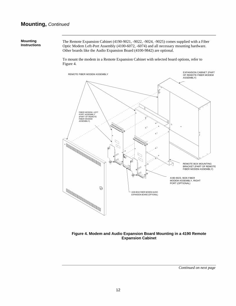
The Remote Expansion Cabinet (4190-9021, -9022, -9024, -9025) comes supplied with a Fiber Optic Modem Left-Port Assembly (4100-6072, -6074) and all necessary mounting hardware. Other boards like the Audio Expansion Board (4100-9842) are optional. To mount the modem in a Remote Expansion Cabinet with selected board options, refer to Figure 4.
4100-9015 (RED) OR - 9016 (BEIGE)REMOTE FIBER MODEM ASSEMBLY, RED
4190-9018 FIBER MODEM AUDIOEXPANSION BOARD (OPTIONAL)
FIBER MODEM,LEFT PORT ASSEMBLY
(PART OF 4100-9015, -9016ASSEMBLY)
4190-9017 FIBER MODEM ASSEMBLY,RIGHT PORT (OPTIONAL)
REMOTE BOX MOUNTING BRACKET(PART OF 4100-9015, -9016 ASSEMBLY)
EXPANSION CABINET(PART OF 4100-9015, -9016
ASSEMBLY)
Figure 4. Modem and Audio Expansion Board Mounting in a 4190 Remote Expansion Cabinet
Continued on next page
Mounting, Continued
Mounting Instructions
REMOTE FIBER MODEM ASSEMBLY EXPANSION CABINET (PART OF REMOTE FIBER MODEM ASSEMBLY)
FIBER MODEM, LEFT PORT ASSEMBLY (PART OF REMOTE FIBER MODEM ASSEMBLY)
4190-9023, 9026 FIBER MODEM ASSEMBLY, RIGHT PORT (OPTIONAL)
REMOTE BOX MOUNTING BRACKET (PART OF REMOTE FIBER MODEM ASSEMBLY)

13
To add a fiber modem audio expansion board to a 4100, see Figure 5. When mounting in any other cabinet, attach mounting plate to enclosure using self-tapping screws or equivalent. Mount the bracket first before mounting the modem and expansion board to the bracket. No standoffs are required. For the two nylon supports posts shipped with the modem, replace them with the posts shipped with the bracket.
Figure 5. Modem and Audio Expansion Board Mounting in a 4100 Cabinet or Transponder Cabinet
Mounting, Continued
Mounting Instructions
MODEM CARD
MODEM AUDIO EXPANSION BOARD
(PART OF 4100-9841)
4100 MOUNTING BRACKET
(PART OF 4100-9841)
4100-9840 MOUNTING PLATE (FOR USE IN 4100
OR OTHER CLOSE-NIPPLED CABINET)

14
All Modem wiring is supervised and power-limited. The following Modem wiring must be within a system box or close-nippled to a system box:
• Digital Audio Riser • 24V Card Power • 4120 Network Left Port • Analog Audio Risers • RUI
The following Modem wiring is allowed to be routed external to a system box:
• 4120 Network Right Port • Analog Audio Riser X-link • RUI X-link
The remainder of this section covers the actual fiber connection and then details wiring specifications with accompanying wiring diagrams for the 4120 Network, Analog Audio Riser, Digital Audio Riser (DAR), and RUI. Note: Ferrite beads are required where the DAR, 4120 Network, and RUI wiring
enters or exits a system box. Except for the 4120 Network Right Port and the RUI X-Link, ferrite beads for all wires are supplied with their respective equipment. Ferrite beads for the RUI X-Link and the 4120 Network Right Port are supplied with the modem (Ferrite Bead Kit Part No. 742-940.)
The fiber optic cable uses a standard ST connector. When mating the connector to the Modem, be sure to align the connector’s key properly to avoid any undue stress to the Modem. Caution: The fiber optic cable can be damaged easily. To prevent permanent damage to
the fiber, avoid bending radii smaller than 1.5 inches (38 mm), or as specified for your particular fiber optic cable.
Wiring
Overview
Fiber Connection
Figure 6. Loop wires through bead as shown

15
These wiring specifications apply to the Modem’s 4120 Network Right Port only (the Left Port must be internal or use close-nippled wiring): The distances listed below allow for the introduction of two lightning suppressors (TEPG Part# 2081-9027) into the communication line for installations where the wiring leaves the building. These distances are shown for 18 AWG (0.8231 mm2) and 24 AWG (0.2047 mm2) wiring at 57.6Kbps and 9600Bps. 57.6 Kbits per/second Using 18 AWG (0.8231 mm2) fire-rated, shielded, twisted-pair cable, transmission distance is: 10,000 Feet (3,048 meters) (with or without Suppressor #2081-9027). Using 24AWG (0.2047 mm2) twisted telephone cable, transmission distance is: 7,000 Feet (2,134 meters) (with or without Suppressor #2081-9027). 9600 bits per/second Using 18AWG (0.8231 mm2) fire-rated, shielded, twisted-pair cable, transmission distance is: 17,000 Feet (5,182 meters) (with or without Suppressor #2081-9027). Using 24AWG (0.2047 mm2) twisted telephone cable, transmission distance is: 12,000 Feet (3,658 meters) (with or without Suppressor #2081-9027).
Continued on next page
Wiring, Continued
4120 Network Wiring Specifications

16
CONNECT TO LEFTPORT OF NETWORKINTERFACE CARD
SHIELD SHOULD BECONNECTED ON ONEEND ONLY. TYPICALLY,CONNECT TO EARTHCONNECTION AT LEFT-PORT CONNECTION ASSHOWN.
SHIELD NOTCONNECTED ATRIGHT PORT
TB2
DA
R +
DA
R -
0V IS
O2
EA
RTH
NO
N IN
V +IN
V -
0V ISO
EA
RTH
NO
N IN
V +IN
V -
DARLEFT RIGHT4120 NETWORK
CONNECT TO RIGHTPORT OF NETWORKINTERFACE CARD
- INV + NON INV
- INV + NON INV
The specifications for the cables to be used in order to meet the above transmission distances are as follows: 18 AWG (0.8231 mm2) Fire-Rated, Twisted-Shielded Cable must not exceed a capacitance between conductors of 58pF per foot and not have a DC resistance greater than 6.385 ohms per 1,000 feet (305 meters). 24 AWG (0.2047 mm2) Twisted, Unshielded Telephone Cable must not exceed a capacitance between conductors of 22pF per foot and not have a DC resistance greater than 25.6 ohms per 1,000 feet (305 meters). When using twisted-shielded pair, the shield is to be connected to Earth ground (Chassis). It is recommended that the shield be connected to Earth ground at one end of the link only (Left Port). When terminating the shield to Earth Ground, it is also preferable to connect it on the chassis as close to the exiting point of the back box as possible. Earth ground is also available on the external terminal block, and on the host’s port connectors. When using 0 V in lieu of Earth ground for shield connection, only one end of the link should be connected (Left Port). Refer to Figure 7 for Modem to 4120 Network wiring information.
Figure 7. Modem to 4120 Network Wiring Diagram
Wiring, Continued
4120 Network Wiring Specifications

17
These wiring specifications apply to the Modem’s Analog Audio Riser Wiring.
• Analog Riser wiring to/from the Modem must connect to either an Analog Audio Controller or an Analog Audio Riser Interface card.
• The Analog Riser X-link can be wired external to the system box, and is part of the head-end side of the wiring loop (that part of loop - 10,000-foot [3,048-meter] limitation).
• All wiring is 18 AWG (0.8231 mm2) to 14 AWG (2.081 mm2), twisted-shielded pair. • Audio wiring is not to be mixed in the same jacket with other wiring (including other
audio wiring). • AC voltage rating: 10 VRMS (maximum). • DC voltage rating: 1 VDC (maximum). • Maximum number of analog interface cards per audio riser: 98. • Maximum of six pairs of Modems in series using standard analog audio. • All wiring that leaves the building requires the 2081-9044 Overvoltage Protector at each
entry or exit to the building. • Maximum wire distance: 10,000 feet (3,048 meters) per copper wired section (for
example, a 10,000-foot [3,048-meter] loop of copper could be connected to another 10,000-foot [3,048-meter] loop of copper if the two loops were electrically isolated via fiber optic cable).
• Wiring must be free of all grounds. • All riser wiring is supervised and power-limited. • “T” tapping is not allowed from the Modem. • The DAR interface wiring, when used for Enhanced Analog Audio (EAA), must be close
nippled because it is not supervised. Refer to Figure 8 for Modem to Analog Audio Riser wiring information and Figure 9 for Modem to Enhanced Analog Audio Riser wiring information.
Continued on next page
Wiring, Continued
Analog Audio Riser Wiring Specifications

18
TB1
24V IN
24C IN
RU
I +R
UI -
RU
I XLIN
K +
RX
LINK
-24CE
AR
THR
ISE
R 1 +
RIS
ER
1 -R
ISE
R 1 X
LINK
+R
ISE
R 1 X
LINK
-24 CE
AR
THR
ISE
R 2 +
RIS
ER
2 -R
ISE
R 2 X
LINK
+R
ISE
R 2 X
LINK
-
24VIN
RUI
CLASS A, HEAD-END MODEM CONNECTIONS
GENERIC CLASS A OR ANY CLASS B CONNECTIONS
FROM: ANALOG AUDIO CONTROLLER +/-CONNECTIONS OR ANALOG RISER INTERFACE
CARD SECONDARY
FROM: ANALOG AUDIO CONTROLLER +/-CONNECTIONS OR ANALOG RISER INTERFACE
CARD SECONDARY-OR-
TO: ANALOG RISER INTERFACE CARD PRIMARY(SEE NOTE)
TO: ANALOG AUDIO CONTROLLER CLASS ARETURN CONNECTIONS OR ANALOG RISER
INTERFACE CARD PRIMARY
RISER 1CONNECTION
RISER 2CONNECTION
RISER 1CONNECTION
RISER 2CONNECTION
RISER 1CONNECTION
WIRE NUTS USED FORSHIELD CONNECTIONS
X-LINK CONNECTIONS ARENOT USED FOR ANY GENERICOR ANY CLASS B MODEM
SHIELD SHOULD BECONNECTED TO 24 C ONLY IFTHE CARD IS SET AS ADEFAULT CONTROLLER, ANDNOT WHEN SET AS A DEFAULT TIC
RISER 2CONNECTION
CLASS A, TAIL-END MODEM CONNECTIONS
ANALOGCH1
ANALOGCH2
TB1
24V IN
24C IN
RU
I +R
UI -
RU
I XLIN
K +
RX
LINK
-24CE
AR
THR
ISE
R 1 +
RIS
ER
1 -R
ISE
R 1 X
LINK
+R
ISE
R 1 X
LINK
-24 CE
AR
THR
ISE
R 2 +
RIS
ER
2 -R
ISE
R 2 X
LINK
+R
ISE
R 2 X
LINK
-
24VIN
RUI
ANALOGCH1
ANALOGCH2
SEE NOTE 2BELOW
TB1
24V IN
24C IN
RU
I +R
UI -
RU
I XLIN
K +
RX
LINK
-24CE
AR
THR
ISE
R 1 +
RIS
ER
1 -R
ISE
R 1 X
LINK
+R
ISE
R 1 X
LINK
-24 CE
AR
THR
ISE
R 2 +
RIS
ER
2 -R
ISE
R 2 X
LINK
+R
ISE
R 2 X
LINK
-
24VIN
RUI
ANALOGCH1
ANALOGCH2
Figure 8. Modem to Analog Audio Riser Wiring Diagram
Wiring, Continued
Analog Audio Riser Wiring Specifications
Note 1: On the head-end modem in a Class A analog audio wiring loop, it is necessary to provide wired connections between the riser’s terminal block positions and the x-link as shown in this diagram. If using 18 AWG (0.8231 mm2) or smaller wire, then make connections as indicated in this diagram. If using wire larger than 18 AWG (0.8231 mm2), then insert a short piece of wire into the terminal block positions and connect the riser and x-link wiring using a wire nut.
Note 2: For Enhanced Analog Audio (EAA) systems, do not make Riser 2 connections.
*The last Riser Interface Card (RIC) in a Class B configuration requires a 4.7 K EOL resistor on its primary input terminals.

19
Enhanced Analog Audio (EAA) eliminates the restriction on the number of modem pairs that can be used in an analog audio system. In an EAA system, you can use only Riser 1 (Channel 1). EAA does not affect the content of the analog riser; it only affects the format of transmission throughout the modem chain. Note: In an EAA system, modems transmit the analog riser via the EAA wiring or
the riser channels. If riser channels are used to pass the riser, the maximum number of modem pairs passing the riser over the riser channels is limited to six.
DARLEFT RIGHT4120 NETWORK
ENHANCED ANALOGAUDIO WIRESAUDIO IN FROM
PREVIOUS MODEMAUDIO OUT TONEXT MODEM
ANALOGAUDIO RISER WIRES
DARLEFT RIGHT4120 NETWORK
ANALOG RISER INTERFACE CARD
CH1CH2
PR
I+
SE
C+
PR
I
PR
I+P
RI
SE
C
SE
C+
SE
C
SH
LD
SH
LD
TB1
TB2
INV
-N
ON
INV
+E
AR
TH0V
ISO
2
0V IS
O2
INV
-N
ON
INV
+E
AR
TH0V
ISO
DA
R -
DA
R +
24V IN
24C IN
RU
I +R
UI -
RU
I XLIN
K +
RX
LINK
-24CE
AR
THR
ISE
R 1 +
RIS
ER
1 -R
ISE
R 1 X
LINK
+R
ISE
R 1 X
LINK
-24 CE
AR
THR
ISE
R 2 +
RIS
ER
2 -R
ISE
R 2 X
LINK
+R
ISE
R 2 X
LINK
-24VIN
RUI
ANALOGCH1
ANALOGCH2
TB2
INV
-N
ON
INV
+E
AR
TH
INV
-N
ON
INV
+E
AR
TH0V
ISO
DA
R -
DA
R +
TB1
24V IN
24C IN
RU
I +R
UI -
RU
I XLIN
K +
RX
LINK
-24CE
AR
THR
ISE
R 1 +
RIS
ER
1 -R
ISE
R 1 X
LINK
+R
ISE
R 1 X
LINK
-24 CE
AR
THR
ISE
R 2 +
RIS
ER
2 -R
ISE
R 2 X
LINK
+R
ISE
R 2 X
LINK
-
24VIN
RUI
ANALOGCH1
ANALOGCH2
Figure 9. Modem to Enhanced Analog Audio Riser Wiring Diagram
Continued on next page
Wiring, Continued
Enhanced Analog Audio (EAA) Riser Wiring Specifications

20
EAA Combinational System In some analog audio systems, more than six modem pairs might be required (therefore requiring EAA usage), but the topology will not allow for all modem-to-modem connections to be close nippled. You are permitted to have modem-to-modem connections made with external wiring; however, those links will not be using the EAA feature and therefore, will be counted toward the limit of six Standard Analog Audio modem pairs in a system. The example in Figure 10 shows such a system where connections between buildings are made with fiber, and intra-building connections are made with field wiring. Note that since EAA is used in the system, the restrictions it imposes apply to the entire analog audio system. Refer to Analog Audio Riser Overview section that appears earlier in this publication.
Figure 10. Enhanced Analog Audio Combinational System Wiring Diagram
Wiring, Continued
Enhanced Analog Audio (EAA) Riser Wiring Specifications
11 1013 1215 14
4 52 3 6 7 8
916
1
Security Building Building A Building B
Building J Building H Building G
Building C Building D Building E
Building FBuilding K
* E1 * E3* E2
* E4* E5* E6
EAA wired between modems(modems are close nippled)
EAA not wired between modems(modems are not close nippled)
WireFiber
* E = EAA link. The bracketed fiber links have EAA wired close nippled between them. Multiple modem links can be counted as a singlelink for the purposes of calculating the total number of Standard Analog Audio links in a system (e.g. E3 above can be counted as one linkeven though it consists of 5 modem pairs).
Transponder 6
AnalogAudioRiser
InterfacePRISEC
Modem
ANAL
OG
FIBER
X-LI
NK
DAR
Modem
ANA
LOG
FIBER
X-LI
NK
DAR
Transponder 4
AnalogAudioRiser
InterfacePRI SEC
Modem
ANA
LOG
FIBER
X-LI
NK
DAR
*
Transponder 5
AnalogAudioRiser
InterfacePRISEC
Modem
ANA
LOG
FIBER
X-LI
NK
DAR
*
EAA is wired in this cabinetsince the modems are closenippled to one another.
*EAA is not wired betweenthese cabinets since they arenot close nippled.
Riser Wires
FiberEAA Wires
Example of internal wiring in the system above:

21
FROM: DIGITAL AUDIO CONTROLLERPRIMARY OR DIGITAL AUDIO RISERINTERFACE SECONDARY
TO: DIGITAL AUDIO CONTROLLERSECONDARY OR DIGITAL AUDIORISER INTERFACE PRIMARY
- OR -
TB2
DA
R +
DA
R -
0V IS
O2
EARTH
NO
N IN
V +
INV -
0V ISO
EARTH
NO
N IN
V +
INV -
DARLEFT RIGHT4120 NETWORK
These wiring specifications apply to the Modem’s Digital Audio Riser Wiring. The Digital Audio Riser (DAR) wiring is always within a system box or close-nippled to a system box. The DAR connection is always either to a Digital Audio Controller or a Digital Audio Riser Interface card. • All riser wiring is supervised and power-limited. • Do not mix audio wiring in the same jacket with other wiring (including other audio wiring). • Maximum number of digital audio interface cards per audio riser: 31. Refer to Figure 11 for Modem to Digital Audio Riser wiring information.
Figure 11. Modem to Digital Audio Riser Wiring Diagram
Wiring, Continued
Digital Audio Riser Specifications

22
These wiring specifications apply to the Modem’s RUI Wiring.
• RUI wiring to/from the Modem must connect to either a CPU/RUI card or a Transponder Interface card.
• The RUI X-link can be wired external to the system box, and is part of the head-end side of the wiring loop (that part of loop - 2,500 foot [762-meter] limitation).
• Wire size must be between 18 AWG (0.8231 mm2) and 12 AWG, (3.309 mm2). • Maximum wiring distance: 2,500 feet (762 meters) per copper wired section (for
example, a 2,500-foot [762-meter] loop of copper could be connected to another 2,500-foot [762-meter] of copper if the two loops were electrically isolated via fiber optic cable).
• “T” tapping is not allowed from the Modem. • Maintain correct polarity on terminal connections. • Do not loop wires under terminals. • All RUI wiring is supervised and power-limited. • All wiring that leaves the building requires the 2081-9044 Overvoltage Protector at each
entry or exit to the building. • Maximum of eight pairs of Modems for RUI if wired Class A.
Refer to Figure 12 for Modem to RUI wiring information.
Continued on next page
Wiring, Continued
RUI Wiring Specifications

23
TB1
24V IN
24C IN
RU
I +R
UI -
RU
I XLIN
K +
RX
LINK
-24CE
AR
THR
ISE
R 1 +
RIS
ER
1 -R
ISE
R 1 X
LINK
+R
ISE
R 1 X
LINK
-24 CE
AR
THR
ISE
R 2 +
RIS
ER
2 -R
ISE
R 2 X
LINK
+R
ISE
R 2 X
LINK
-
24VIN
RUI
CLASS A, HEAD-END MODEM CONNECTIONS
GENERIC CLASS A, OR ANY CLASS B CONNECTIONS
FROM: CPU/RUI CARD CLASS BCONNECTIONS OR TRANSPONDER
INTERFACE SECONDARY-OR-
TO: TRANSPONDER INTERFACECARD PRIMARY
FROM: CPU/RUI CARD CLASS BCONNECTIONS OR TRANSPONDER
INTERFACE SECONDARY
TO: CPU/RUI CARD CLASS ARETURN OR TRANSPONDER
CARD PRIMARY
WIRE NUTS USED FORSHIELD CONNECTIONS
X-LINK CONNECTIONS ARENOT USED FOR ANY GENERICOR ANY CLASS B MODEM
SHIELD SHOULD BECONNECTED TO 24 C ONLY IFTHE CARD IS SET AS ADEFAULT RUI, ANDNOT WHEN SET AS A DEFAULT TIC
CLASS A, TAIL-END MODEM CONNECTIONS
ANALOGCH1
ANALOGCH2
TB1
24V IN
24C IN
RU
I +R
UI -
RU
I XLIN
K +
RX
LINK
-24CE
AR
THR
ISE
R 1 +
RIS
ER
1 -R
ISE
R 1 X
LINK
+R
ISE
R 1 X
LINK
-24 CE
AR
THR
ISE
R 2 +
RIS
ER
2 -R
ISE
R 2 X
LINK
+R
ISE
R 2 X
LINK
-
24VIN
RUI
ANALOGCH1
ANALOGCH2
TB1
24V IN
24C IN
RU
I +R
UI -
RU
I XLIN
K +
RX
LINK
-24CE
AR
THR
ISE
R 1 +
RIS
ER
1 -R
ISE
R 1 X
LINK
+R
ISE
R 1 X
LINK
-24 CE
AR
THR
ISE
R 2 +
RIS
ER
2 -R
ISE
R 2 X
LINK
+R
ISE
R 2 X
LINK
-
24VIN
RUI
ANALOGCH1
ANALOGCH2
Figure 12. Modem to RUI Wiring Diagram
Wiring, Continued
RUI Wiring Specifications

24
ANALOGCH 2
ANALOGCH 1
FIBER MODEM MODEM
FIBER MODEM MODEMAUDIO EXPANSION CARD
CLASS A, HEAD END MODEM CONNECTIONS
CLASS B CONNECTIONS
CLASS A, TAIL END MODEM CONNECTIONS
CONNECT HARNESS 734-191BETWEEN MODEM P3 AND
EXPANSION BOARD P3. BE SURETO ORIENT THE HARNESS SO THE
COLORED WIRE CONNECTS TOPIN 1 ON THE CONNECTOR
FROM: 4100 LEGACY AUDIOSIGNAL CARD PRIMARY
TERMINALSRISER 2
CONNECTIONRISER 1CONNECTION
FROM: 4100 LEGACY AUDIOSIGNAL CARD PRIMARY
TERMINALSRISER 2
CONNECTIONRISER 1CONNECTION
FROM: 4100 LEGACY AUDIOSIGNAL CARD SECONDARY
TERMINALSRISER 2
CONNECTIONRISER 1CONNECTION
RUI 24VIN INPUT
OUTPUT
RIS
ER
2 XLIN
K -
RIS
ER
2 XLIN
K +
RIS
ER
2 -R
ISE
R 2 +
EA
RTH
24 CR
ISE
R 1 X
LINK
-R
ISE
R 1 X
LINK
+R
ISE
R 1 -
RIS
ER
1 +
RIS
ER
2 -R
ISE
R 2 +
RIS
ER
1 -R
ISE
R 1 +
RIS
ER
2 XLIN
K -
RIS
ER
2 XLIN
K +
RIS
ER
2 -R
ISE
R 2 +
RIS
ER
1 XLIN
K -
RIS
ER
1 XLIN
K +
RIS
ER
1 -R
ISE
R 1 +
EA
RTH
24 CR
UI X
LINK
-R
UI X
LINK
+R
UI -
RU
I +24 C
IN24 V
INTB
1
TB1
TB2
ANALOGCH 2
ANALOGCH 1
FIBER MODEM MODEM
FIBER MODEM MODEMAUDIO EXPANSION CARD
RUI 24VIN INPUT
OUTPUT
RIS
ER
2 XLIN
K -
RIS
ER
2 XLIN
K +
RIS
ER
2 -R
ISE
R 2 +
EA
RTH
24 CR
ISE
R 1 X
LINK
-R
ISE
R 1 X
LINK
+R
ISE
R 1 -
RIS
ER
1 +
RIS
ER
2 -R
ISE
R 2 +
RIS
ER
1 -R
ISE
R 1 +
RIS
ER
2 XLIN
K -
RIS
ER
2 XLIN
K +
RIS
ER
2 -R
ISE
R 2 +
RIS
ER
1 XLIN
K -
RIS
ER
1 XLIN
K +
RIS
ER
1 -R
ISE
R 1 +
EA
RTH
24 CR
UI X
LINK
-R
UI X
LINK
+R
UI -
RU
I +24 C
IN24 V
INTB
1
TB1
TB2
All wiring shown in Figure 13 must be close nippled.
Figure 13. Modem Audio Expansion Board Wiring Diagram
Wiring, Continued
Fiber Modem Audio Expansion Board Wiring Specifications
Note 1: In Class B installations, install a 4.7 K Ohm resistor at each Audio Input Option card input terminal in the receiving 4100U/4100ES cabinet.
Note 2: All wiring shown must be close nippled.

25
4100U, 4100ES and 401ES The Modem has two Core 4 connectors (P9 & P10) and a terminal block (TB1) for connecting 24 VDC power. (See Figure 1 and Figure 14 [on next page] for locations of Connectors P9 & P10 and Terminal Block TB1.) The source of card power to the Modem must be an uninterruptible source (such as card power), and not a resettable source such as AUX power. The Modem’s power must not be interrupted because all wired interfaces would fail during the power failure (roughly equivalent to disconnecting all the attached wires for the duration of the power failure). The intended installation in a 4100U, 4100ES or 4010ES system is to use Connectors P9 & P10. Because these two connectors are electrically identical, power can be daisy chained as needed in and out of the Modem. The connection can be made using a standard PDI bay-to-bay harness. Make your connection to the mating connector on the local power supply (SPS, RPS, XPS or MSS in the case of a 4010ES system). If the connector on the power supply is occupied (as may be the case in a Miniplex Transponder cabinet), then connect the Modem power harness to one of the PDI connectors on the PDI to which the power supply is connected. NOTE: Do not use the daisy-chain connections for anything except modems. The communication-wiring portion of the harness is not connected to the modem and is not daisy chained between the connectors. 4100 (Audio [Expansion Board] and 4120 Network Only) When connecting power to a 4100 system, connect TB1-1 and TB1-2 on the Modem to the system power supply: • 24V…TB2-11 or TB2-12 • 0 V….TB2-9 or TB2-10 4010 (4120 Network Only) When connecting power to a 4010 system, connect TB1-1 and TB1-2 on the Modem to auxiliary power (TB5) on the system board. 4020 (4120 Network Only) When connecting power to a 4020 system, connect TB1-1 and TB1-2 on the Modem to the “A” tap on the Power Interface Board. Connect to TB2 as follows: • 24V…TB2-1 or TB2-2 • 0 V….TB2-3 or TB2-4
Continued on next page
Connecting Power to the Modem
Where to Connect Power

26
4100U/4100ES/4010ES Figure 14. Modem Power Connections
Connecting Power to the Modem, Continued
Where to Connect Power

27
Use this section as an aid in testing and troubleshooting a fiber modem pair installation. It should be noted that a fiber fault can cause a trouble on all connected media. A fiber fault must be resolved before any further troubleshooting or testing can be performed. The following general checkouts should always be performed upon installation of modem pair:
1. Verify that the “Fiber Fault” LED is not illuminated. If it is not, then the fiber connection is operating. (See Table 12 and the Fiber Fault LED section [next page] for details on LED indications.) If it is illuminated, verify the following:
a. The modems are actually a mated pair. Perform this action by checking the assembly number of the fiber optic transceiver board that mounts to the main board. For multimode fiber, one transceiver should be 566-714 (left port), and the other should be 566-715 (right port). For single-mode fiber, one transceiver should be 566-716 (left port), and the other should be 566-717 (right port).
b. The fiber optic cable is properly connected, and the connections are clean. c. The total attenuation and distance are within limits. d. If all of the above conditions are met and the Fiber Fault LED is still
illuminated, then it may be necessary to test the link using an OTDR. OTDR tests should be done using industry standard methods and industry standard pass/fail criteria.
2. Verify that the switch configurations are properly set. If the switches are set improperly, the modem may not be in the proper mode, and may not be capable of entering a degraded mode or successfully report troubles to the connected equipment.
3. Verify that the wired connections are in the proper terminal block positions. For RUI and Analog Audio (if used), be certain that the risers connect to the RUI and Riser positions and not the x-link connections. The only time anything should be connected to the x-link connections is in a Class A system between the head and tail-end modems.
Note: All wiring faults (shorts and opens) on a wired loop that is electrically isolated from the main panel by fiber will always be reported as an open on the panel side of the loop. Modems report this way to convey fault information back to the panel without causing a short circuit on the panel side of the loop.
Testing and Troubleshooting
General

28
The Modem has LED indicators as shown in Table 12. Refer to Figure 1 for LED locations.
Table 12. LED Indications
Reference Function Details LED1 AAR1 FAULT Indicates a fault condition on Analog Audio Riser Channel 1. LED2 AAR2 FAULT Indicates a fault condition on Analog Audio Riser Channel 2. LED3 FIBER FAULT Indicates a failure of the fiber optic link. LED4 RUI FAULT Indicates a fault condition on RUI. LED5 POWER Indicates the presence of 24V card power. LED6 4120 TX R Flashes while data is actively being transmitted on the right
network port. LED7 4120 RX R Flashes while data is actively being received on the right network
port. LED8 4120 TX L Flashes while data is actively being transmitted on the left network
port. LED9 4120 RX L Flashes while data is actively being received on the left network
port.
LED10 DAR TX ON when DAR transceiver is in transmit mode. OFF when in the receive mode. Flashes when the Modem is searching for an active DAR (fault if flashing).
Note: The RUI and Analog Riser LEDs are intended as troubleshooting aids only. In some configurations, they will not indicate a fault on their wiring.
There are two severity levels for fiber faults. One level is a momentary fault that’s indicated by the fiber fault LED for any data error on the fiber. In a properly operating fiber link, momentary faults occur very rarely or never. If the fiber fault LED illuminates frequently (e.g., more than once in five minutes), then there may be a problem with the fiber link. The other level of fault is a fiber trouble. In this case, troubles are reported at the panel and the fiber fault LED illuminates much of the time or continuously; you definitely need to check out the fiber link. The goal for any link during installation is to have no illumination of the modem’s fiber fault LED.
Use the “DAR TX” LED to aid in diagnosing DAR faults. If the DAR LED is OFF, then the DAR is in the receive mode. It remains in the receive mode if the DAR is not enabled or if the modem is actively receiving a DAR on the wired connection. If the DAR LED is ON, then the modem is actively transmitting a DAR on the wired connection. If the DAR LED turns ON and OFF at a 2-second rate, then the modem is searching to find a DAR on the fiber and the wired interface. In the event of a DAR fault, check the following:
1. The DAR enable switch is properly set. 2. The DAR LED is OFF on a modem receiving the DAR from the wired interface. 3. The DAR LED is ON for a modem transmitting the DAR to the wired interface.
Testing and Troubleshooting, Continued
LED Indications
Fiber Fault LED
Digital Audio Riser (DAR)

29
If the analog audio interface is not operating properly, verify the following: 1. The analog audio switches are properly set. 2. A good quality voltmeter can be used to measure the riser’s RMS voltage on the panel
side loop, and then be re-measured on isolated loops to determine what modem pair could be causing a fault. Any signal present on one side of a fiber connection should be present on the other.
3. The wired interface is connected to the proper terminal block positions. 4. The analog audio level select jumpers are properly set.
Note: A fault on the analog audio interface could result from a fault on a
separate-wired interface, and could be induced by a connected modem that’s indicating to the panel that there is a fault on an isolated wired loop.
If the network interface is not operating properly, verify the following: 1. The network switch settings are all properly configured. 2. The network connections are in the proper ports. A given network wire pair should
always enter either the left or right port of a modem, and leave via the mating modem’s opposite port (for example, in on left, out on right, or vice versa).
3. The network interface LEDs operate in the same way as those found on a network interface card; that is, the TX and RX LEDs illuminate only while data is actively being passed in their respective directions.
If the RUI interface is not operating properly, verify the following: 1. The RUI configuration switches are properly set. 2. The wired interface is connected to the proper terminal block positions.
Note: A fault on RUI interface could result from a fault on a separate-wired
interface, and could be induced by a connected modem that’s indicating to the panel that there is a fault on an isolated wired loop.
A basic system checkout should always be performed on a new installation to verify that all modems are properly configured. Do a basic checkout because a wrongly configured modem could behave normally in normal mode, but not be capable of entering degraded mode or reporting troubles to the panel. Basic tests include introducing shorts and open circuits on each of the wired links within a system as well as interrupting each fiber optic link and verifying system operation.
Testing and Troubleshooting, Continued
Analog Audio
4120 Network
RUI
System Checkout

30
Use the procedures in the Table 13 to confirm that all interfaces (that are in use) are supervised for opens, shorts, and grounds. The left two columns indicate the interface/test method while the right column indicates the system response.
Table 13. Testing Circuit Supervision
Interface Test Condition Corresponding System Indication/Response Digital Audio Riser Short - apply a zero ohm jumper across
the riser wires. Panel indicates riser trouble at receiving cards. System enters degraded mode if wired Style 7.
Digital Audio Riser Open - open the riser wires. Panel indicates riser trouble at receiving cards. System enters degraded mode if wired Style 7.
Digital Audio Riser Ground - place a 10 K or smaller value resistor from supervised wiring to earth ground.
Panel indicates earth ground and riser trouble at receiving cards. System enters degraded mode if wired Style 7.
Analog Audio Riser Short - apply a zero ohm jumper across the riser wires.
Panel indicates a short if the jumper is on the local side of wiring loop, or an open if the jumper is on the remote side of the loop. Class A only: If the short is optically isolated from the head-end panel, then the system enters degraded mode.
Analog Audio Riser Open - open the riser wires or remove the End-Of-Line resistor (Class B only).
Panel indicates an open if Class B. If wired Class A. enters degraded mode (indicates Class A fault).
Analog Audio Riser Ground- place a 10k or smaller value resistor from supervised wiring to earth ground.
Panel indicates earth ground.
4120 Network Short - apply a zero ohm jumper across the network wires.
Panel indicates network trouble. System enters degraded mode if wired Style 7.
4120 Network Open - open the network wires. Panel indicates network trouble. System enters degraded mode if wired Style 7.
4120 Network Ground - place a 10 K or smaller value resistor from supervised wiring to earth ground.
Panel indicates earth ground and network wiring fault trouble. System enters degraded mode if wired Style 7.
RUI Short - apply a zero ohm jumper across the RUI wires.
Panel indicates cards missing if it is wired Class B. If wired Class A, the system enters degraded mode (indicates Class A fault).
RUI Open – open the RUI wires. Panel indicates cards missing if it is wired Class B. If wired Class A, the system enters degraded mode (indicates Class A fault).
RUI Ground - place a 10 K or smaller value resistor from supervised wiring to earth ground.
Panel indicates earth ground.
Testing and Troubleshooting, Continued
Testing Circuit Supervision

31
1 3
2
4
This section shows sample configurations for each interface.
Internal Building or Multi-Building Configurations…Figures A-1 through A-12 Hub Configurations…Figures A-13 through A-15 Interconnected Loop and Star Configurations…Figures A-16 through A-19 Fiber-Connected Information Management System (IMS) Configuration…Figure A-20 Fiber Modem Audio Expansion Board…Figures A-21 and A-22
• Multiple panels (4) in one building • Multiple buildings (4) each with one panel
Figure A-1. Internal Building or Multi-Building Configuration Class A/Style 7 or Style 6
Appendix – Sample Configurations
Overview
Internal Building or Multi-Building Configuration – Class A/Style 7 or Style 6
Refer to the following pages for detailed implementation of the Internal Building or Multi-Building Configuration (Class A/Style 7 or Style 6): RUI Page 32 4120 Network Page 33 Analog Audio Page 34 Enhanced Analog Audio Page 35 Digital Audio Page 36

32
RUI WIRESFIBER
This is a head end modem because it is wired to the primaryside of the cabinet.
SW 1-4 Off head endSW 1-3 On not generic (because it’s a head end)SW 1-2 On transponder interface (it’s not driving the copper)
This is a generic modem (not head end or tail end).
SW 1-4 Off (ignored since it is a generic modem)SW 1-3 Off genericSW 1-2 Off RUI (it’s driving the copper)
This is a generic modem (not head end or tail end).
SW 1-4 Off (ignored since it is a generic modem)SW 1-3 Off genericSW 1-2 On Transponder interface (it’s not driving the copper)
This is a tail end modem because it is wired to the secondaryside of the cabinet.
SW 1-4 On tail endSW 1-3 On not generic (because it’s a tail end)SW 1-2 On transponder interface (it’s not driving the copper)
This is a generic modem (not head or tail end).
SW 1-4 Off (ignored since it is a generic modem)SW 1-3 Off genericSW 1-2 On transponder interface (it’s not driving the copper)
(the CPU/RUI card is)
Transponder 4
SHIELD*
FIB
ER
FIB
ER
Modem
TIC
Modem
SE
C
PR
I
RU
I
RU
I
Transponder 3
FIB
ER
FIB
ER
Modem
TIC
Modem
SE
C
PR
I
RU
I
RU
I
Head End 1SHIELD*
CPUMother-Board
orRUICard
Modem
SE
C
PR
I
RU
IX
-LIN
K
FIB
ER
ModemFI
BE
R
RU
IX
-LIN
K
Transponder 2
SHIELD*
FIB
ER
FIB
ER
Modem
TIC
Modem
SE
C
PR
I
RU
I
RU
I
SHIELD*
This is a generic modem (not head or tail end).
SW 1-4 Off (ignored since it is a generic modem)SW 1-3 Off genericSW 1-2 Off RUI (it’s driving the copper)
This is a generic modem (not head or tail end).
SW 1-4 Off (ignored since it is a generic modem)SW 1-3 Off genericSW 1-2 Off RUI (it’s driving the copper)
This is a generic modem (not head or tail end).
SW 1-4 Off (ignored since it is a generic modem)SW 1-3 Off genericSW 1-2 On transponder interface (it’s not driving the copper)
Figure A-2. RUI Class A/Style 7
Appendix – Sample Configurations, Continued
RUI (excluding 4120 Network) Class A/Style 7
Switch 1-5 (Enable RUI interface) and Switch 1-1 (Class A wiring) both ON for all modems in this configuration. *Shields are to be connected at one end of each wiring link to either Earth or 24C as required.
Ferrite beads must be installed at the point where copper wiring exits the system box. Note: All switches not listed are set according to the application of their respective
interface.

33
Transponder 4
SHIELD*
Transponder 3
Transponder 2Head End 1
NetworkInterface
CardFI
BE
RModem Modem
ModemModemFI
BE
RFI
BE
R
FIB
ER
FIB
ER
SHIELD*
SHIELD*
SHIELD*
FIBER
WIRE
L
L
Modem
FIB
ER
Modem
FIB
ER
FIB
ER
ModemModem
NetworkInterface
Card
NetworkInterface
Card
RR
R
L
L
R L
LL
R
R R
L
R NetworkInterface
Card
Figure A-3. 4120 Network Class A/Style 7
Appendix – Sample Configurations, Continued
4120 Network (excluding RUI) Class A/Style 7
Switch 1-5 OFF to enable the 4120 Network Interface. SW1-6 (4120 Network Protocol) and Switch SW1-7 (4120 Network Speed) are set the same for all modems in the system. They are set to match the Network Interface Cards (NICs) in the system. Note: All switches not listed are set according to the application of their respective
interface. Refer to Figure 4 for shield connections.

34
ANALOG WIRES
FIBER
SHIELD*
SHIELD* SHIELD*
SHIELD*
Head End 1 Transponder 2
Transponder 4 Transponder 3
FIB
ER
FIB
ER
FIB
ER
DA
R DA
R
DA
R AN
ALO
G
AN
ALO
GX
-LIN
K
AN
ALO
GX
-LIN
K
SE
C
PR
I
SE
C
PR
IAnalogAudio
Controller
AnalogAudioRiser
Interface
Modem ModemModem
FIB
ER
AN
ALO
G
Modem
FIB
ER
AN
ALO
G
SE
C
PR
I
AnalogAudioRiser
InterfaceModem
FIB
ER
AN
ALO
G
Modem
FIB
ER
AN
ALO
G
SE
C
PR
I
AnalogAudioRiser
InterfaceModem
FIB
ER
AN
ALO
G
Modem
Channel 1:This is a head end modem because it is wired to the primaryside of the head end cabinet.
SW 2-4/SW 3-4 Off head endSW 3-2/SW 3-3 On not generic (because it’s a head end)SW 2-2/SW 3-2 On riser interface (it’s not driving the copper)
This is a generic modem (not head or tail end).
SW 2-4/SW 3-3 Off (ignored since it’s a generic modem)SW 2-3/SW 3-3 Off genericSW 2-2/SW 3-2 Off controller (it’s driving the copper)
This is a generic modem (not head or tail end).
SW 2-4/SW 3-4 Off (ignored since it’s a generic modem)SW 2-3/SW 3-3 Off genericSW 2-2/SW 3-2 On riser interface (it’s driving the copper)
This is a tail end modem because it is wired to the secondaryside of the head end cabinet.
SW 2-4/SW 3-4 On tail endSW 2-3/SW 3-3 On not generic (because it’s a tail end)SW 2-1/SW 3-2 On riser interface (it’s not driving the copper)
(the analog controller card is)
This is a generic modem (not head or tail end).
SW 2-4/SW 3-4 Off (ignored since it’s a generic modem)SW 2-3/SW 3-3 Off genericSW 2-2/SW 3-2 On riser interface
(it’s not driving the copper)
This is a generic modem (not head or tail end).
SW 2-4/SW 3-4 Off (ignored since it’s a generic modem)SW 2-3/SW 3-3 Off genericSW 2-2/SW 3-2 Off controller (it’s driving the copper)
This is a generic modem (not head or tail end).
SW 2-4/SW 3-4 Off (ignored since it’s a generic modem)SW 2-3/SW 3-3 Off genericSW 2-2/SW 3-2 On riser interface
This is a generic modem (not head or tail end).
SW 2-4/SW 3-4 Off (ignored since it’s a generic modem)SW 2-3/SW 3-3 Off genericSW 2-2/SW 3-2 Off controller (it’s driving the copper)
(it’s not driving the copper)
Figure A-4. Analog Audio Class A/Style 6
Appendix – Sample Configurations, Continued
Analog Audio Class A/Style 6
SW2-5, SW3-5 (Analog Channel Enable) and SW2-1, SW3-1 (Class A wiring) both ON for all modems in this configuration. *Shields are to be connected at one end of each wiring link to either Earth or 24C, as required.
Ferrite beads must be installed at the point where copper wiring exits the system box. Note: All switches not listed are set according to the application of their respective
interface. Switch positions are indicated as follows: "Riser 1 position/Riser 2 position."

35
ANALOG WIRES
EAA WIRES
FIBER
SHIELD*
SHIELD* SHIELD*
SHIELD*
Head End 1 Transponder 2
Transponder 4 Transponder 3
FIBE
R
FIBE
R
FIBE
R
DAR D
AR
DAR AN
ALO
G
ANAL
OG
X-LI
NK
ANAL
OG
X-LI
NK
SEC
PRI
SEC
PRIAnalog
AudioController
AnalogAudioRiser
Interface
Modem ModemModem
FIBE
RD
AR
ANAL
OG
Modem
FIBE
RD
AR
ANAL
OG
SEC
PRI
AnalogAudioRiser
InterfaceModem
FIBE
RD
AR
ANAL
OG
Modem
FIBE
RD
AR
ANAL
OG
SEC
PRI
AnalogAudioRiser
InterfaceModem
FIBE
RD
AR
ANAL
OG
Modem
Channel 1:This is a head end modem because it is wired to the primaryside of the head end cabinet.
SW 2-6 Off not wired (no EAA connection)SW 2-4 Off head endSW 2-3 On not generic (because it’s a head end)SW 2-2 On riser interface (it’s not driving the copper)
This is a tail end modem because it is wired to the secondaryside of the head end cabinet.
SW 2-6 Off not wired (no EAA connection)SW 2-4 On tail endSW 2-3 On not generic (because it’s a head end)SW 2-2 On riser interface (it’s not driving the copper)
This is a generic modem (not head or tail end).
SW 2-6 On wired (EAA connected)SW 2-4 Off (ignored since it’s a generic modem)SW 2-3 Off genericSW 2-2 Off controller (it’s driving the copper)
This is a generic modem (not head or tail end).
SW 2-6 On wired (EAA connected)SW 2-4 Off (ignored since it’s a generic modem)SW 2-3 Off genericSW 2-2 On riser interface (it’s not driving the copper)
(the analog controller card is)
This is a generic modem (not head or tail end).
SW 2-6 On wired (EAA connected)SW 2-4 Off (ignored since it’s a generic modem)SW 2-3 Off genericSW 2-2 On riser interface (it’s not driving the copper)
This is a generic modem (not head or tail end).
SW 2-6 On wired (EAA connected)SW 2-4 Off (ignored since it’s a generic modem)SW 2-3 Off genericSW 2-2 Off controller (it’s driving the copper)
This is a generic modem (not head or tail end).
SW 2-6 On wired (EAA connected)SW 2-4 Off (ignored since it’s a generic modem)SW 2-3 Off genericSW 2-2 On riser interface (it’s not driving the copper)
This is a generic modem (not head or tail end).
SW 2-6 On wired (EAA connected)SW 2-4 Off (ignored since it’s a generic modem)SW 2-3 Off genericSW 2-2 Off controller (it’s driving the copper)
Figure A-5. Enhanced Analog Audio (EAA) Class A/Style 6
Appendix – Sample Configurations, Continued
Enhanced Analog Audio (EAA) (limited to Channel 1 & excluding Digital Audio) Class A/Style 6
SW2-1 (Class A) ON for all modems in this configuration. SW2-5 (Analog Enable) ON for all modems in this configuration. SW2-7 (Enhanced Analog Enable) ON for all modems in this configuration. Note: All switches not listed are set according to the application of their respective
interface.

36
Transponder (or remote node) - 4
SE
C
PR
I
Transponder (or remote node) - 3
Transponder (or remote node) - 2Head End - 1
DigitalAudio
Controller
DigitalAudioRiser
Interface
PR
I
SE
C
FIB
ER
SHIELD*
Modem
Modem
FIB
ER
Modem
FIB
ER
DA
R
DA
R
FIB
ER
DA
R
DA
R
Modem
SE
C
PR
I
DigitalAudioRiser
InterfaceModemFI
BE
RModem
FIB
ER
DA
R
DA
R
PR
I
SE
C
DigitalAudioRiser
InterfaceModem
FIB
ER
Modem
FIB
ER
DA
R
DA
R
Figure A-6. Digital Audio (excluding Analog Audio Channel 1) Class A/Style 7
Appendix – Sample Configurations, Continued
Digital Audio (excluding Analog Audio Channel 1) Class A/Style 7
Settings for all switches in this configuration: Switch 2-8 (DAR Enable) ON for all modems in this configuration. Note: All switches not listed are set according to the application of their respective
interface.

37
• Multiple panels (4) in one building • Multiple buildings (4) each with one panel
Figure A-7. Internal Building or Multi-Building Configuration Class B/Style 4
Appendix – Sample Configurations, Continued
Internal Building or Multi-Building Configuration – Class B/Style 4
Refer to the following pages for detailed implementation of the Internal Building or Multi-Building Configuration (Class B/Style 4): RUI Page 38 Analog Audio Page 39 Enhanced Analog Audio Page 40 Digital Audio Page 41

38
Figure A-8. RUI Class B/Style 4
Appendix – Sample Configurations, Continued
RUI (Excluding 4120 Network) Class B/Style 4
Settings for all modems in this configuration: SW1-1 is OFF (set for Class B wiring). SW1-3 is OFF (set as generic - all modems are generic in Class B configurations). SW1-4 is OFF (it is ignored since the modems are generic). SW1-5 is ON (enable RUI interface). *Shields are to be connected at one end of each wiring link to either Earth or 24C, as required. Ferrite beads must be installed at the point where copper wiring exits the system box. Note: All switches not listed are set according to the application of their respective interface.
Head End
Transponder Transponder
Transponder
RUI WIRES (2)
FIBER
FIBER
FIBER
FIB
ER
SHIELD*
SHIELD*
SHIELD*
CPUMother-Board
orRUICard
AnalogAudioRiser
Interface
Modem
SE
CS
EC
PR
IP
RI
TIC
SE
C
PR
I
TIC
SE
C
PR
I
FIB
ER
Modem
FIB
ER
Modem
RU
IR
UI
RU
IR
UI R
UI
RU
I
FIB
ER
Modem
FIB
ER
Modem
FIB
ER
Modem
FIB
ER
1-2 Off RUI (it’s driving the copper) 1-2 Off RUI (it’s driving the copper)1-2 On transponder interface (it’s not driving the copper)
1-2 On transponder interface (it’s not driving the copper) 1-2 On transponder interface (it’s not driving the copper)1-2 Off RUI (it’s driving the copper)

39
Analog AudioHead End
Transponder (or remote node) Transponder (or remote node)
Transponder (or remote node)
ANALOG AUDIO WIRES (2/channel)FIBER
FIBER
FIBER
FIBE
R
SHIELD*
SHIELD*
SHIELD*
SHIELD*
AnalogAudio
Controller
AnalogAudioRiser
Interface
Modem
SEC
SEC
PRI
PRI
AnalogAudioRiser
Interface
SEC
PRI
AnalogAudioRiser
Interface
SEC
PRI
DAR
ANAL
OG
FIBE
RModem
DAR
ANAL
OG
FIBE
R
Modem
DAR
ANAL
OG
FIBE
RModem
DAR
ANAL
OG
FIBE
R
Modem
DAR
ANAL
OG
FIBE
RModem
DAR
ANAL
OG
FIBE
R
Riser 1 setting:SW 2-2 On Riser interface (receives analog riser).
Riser 2 setting:SW 3-2 On Riser interface (receives analog riser).
Riser 1 setting:SW 2-2 Off Controller (transmits analog riser).
Riser 2 setting:SW 3-2 Off Controller (transmits analog riser).
Riser 1 setting:SW 2-2 On Riser interface (receives analog riser).
Riser 2 setting:SW 3-2 On Riser interface (receives analog riser).
Riser 1 setting:SW 2-2 Off Controller (transmits analog riser).
Riser 2 setting:SW 3-2 Off Controller (transmits analog riser).
Riser 1 setting:SW 2-2 On Riser interface (receives analog riser).
Riser 2 setting:SW 3-2 On Riser interface (receives analog riser).
Riser 1 setting:SW 2-2 Off Controller (transmits analog riser).
Riser 2 setting:SW 3-2 Off Controller (transmits analog riser).
Figure A-9. Analog Audio Class B/Style 4
Appendix – Sample Configurations, Continued
Analog Audio Class B/Style 4
Settings for all modems in this configuration: SW2-1 and 3-1 are OFF (set for Class B wiring). SW2-3 and 3-3 are OFF (set as generic - all modems are generic in Class B configurations). SW2-4 and 3-4 are OFF (these are ignored since the modems are generic). SW2-5 and 3-5 are ON (enable CH1 & CH2 interface). *Shields are to be connected at one end of each wiring link to either Earth or 24C, as required.
Ferrite beads must be installed at the point where copper wiring exits the system box. Note: All switches not listed are set according to the application of their respective
interface.

40
Analog AudioHead End
Riser 1 setting:SW 2-2 On Riser interface (receives analog riser).
Enhanced Audio setting:SW 2-7 On Enable Enhanced Analog AudioSW 2-6 Off Enhanced Audio not wired
Riser 1 setting:SW 2-2 Off Controller (transmits analog riser).
Enhanced Audio setting:SW 2-7 On Enable Enhanced Analog AudioSW 2-6 Off Enhanced Audio not wired
Riser 1 setting:SW 2-2 On Riser Interface (receives analog riser).
Enhanced Audio setting:SW 2-7 On Enable Enhanced Analog AudioSW 2-6 On Enhanced Audio wired
Riser 1 setting:SW 2-2 Off Controller (transmits analog riser).
Enhanced Audio setting:SW 2-7 On Enable Enhanced Analog AudioSW 2-6 On Enhanced Audio wired
Riser 1 setting:SW 2-2 Off Controller (transmits analog riser).
Enhanced Audio setting:SW 2-7 On Enable Enhanced Analog AudioSW 2-6 On Enhanced Audio wired
Riser 1 setting:SW 2-2 On Riser Interface (receives analog riser).
Enhanced Audio setting:SW 2-7 On Enable Enhanced Analog AudioSW 2-6 On Enhanced Audio wired
Transponder (or remote node) Transponder (or remote node)
Transponder (or remote node)
ANALOG AUDIO WIRES (2)ENHANCED AUDIO WIRES (2)FIBER
FIBER
FIBER
FIB
ER
SHIELD*
SHIELD*
SHIELD*
SHIELD*
AnalogAudio
Controller
AnalogAudioRiser
Interface
Modem
SE
CS
EC
PR
IP
RI
AnalogAudioRiser
Interface
SE
C
PR
I
AnalogAudioRiser
Interface
SE
C
PR
I
DA
R
AN
ALO
GFI
BE
R
Modem
DA
R
AN
ALO
GFI
BE
R
Modem
DA
R
AN
ALO
GFI
BE
R
Modem
DA
R
AN
ALO
GFI
BE
R
Modem
DA
R
AN
ALO
GFI
BE
R
Modem
DA
R
AN
ALO
GFI
BE
R
Figure A-10. Enhanced Analog Audio (EAA) Class B/Style 4
Appendix – Sample Configurations, Continued
Enhanced Analog Audio (EAA) (limited to Channel 1 & excluding Digital Audio) Class B/Style 4
Settings for all modems in this configuration: SW2-1 is OFF (set for Class B wiring). SW2-3 is OFF (set as generic - all modems are generic in Class B configurations). SW2-4 is OFF (these are ignored since the modems are generic). SW2-5 is ON (enable CH1 interface). *Shields are to be connected at one end of each wiring link to either Earth or 24C, as required. Ferrite beads must be installed at the point where copper wiring exits the system box. Note: All switches not listed are set according to the application of their respective interface.

41
Transponder (or remote node)Transponder (or remote node)
Transponder (or remote node)Digital AudioHead End
FIBER
FIB
ER
FIBER
DigitalAudio
Controller
PR
I
SE
C DigitalAudioRiser
Interface
DigitalAudioRiser
Interface
SE
C
PR
I
SE
C
PR
I
DigitalAudioRiser
Interface
FIB
ER
Modem Modem
ModemModemModem
FIB
ER
FIB
ER
FIB
ER
FIB
ER
FIB
ER
DAR WIRES (2)
Modem
PR
I
SE
C
FIBER
DA
R DA
R
DA
R
DA
RDA
R
DA
R
Figure A-11. Digital Audio (excluding Analog Audio Channel 1) Class B/Style 4
Appendix – Sample Configurations, Continued
Digital Audio (excluding Analog Audio Channel 1) Class B/Style 4
Settings for all switches in this configuration: Switch 2-8 (DAR Enable) ON for all modems in this configuration. Note: All switches not listed are set according to the application of their respective interface.
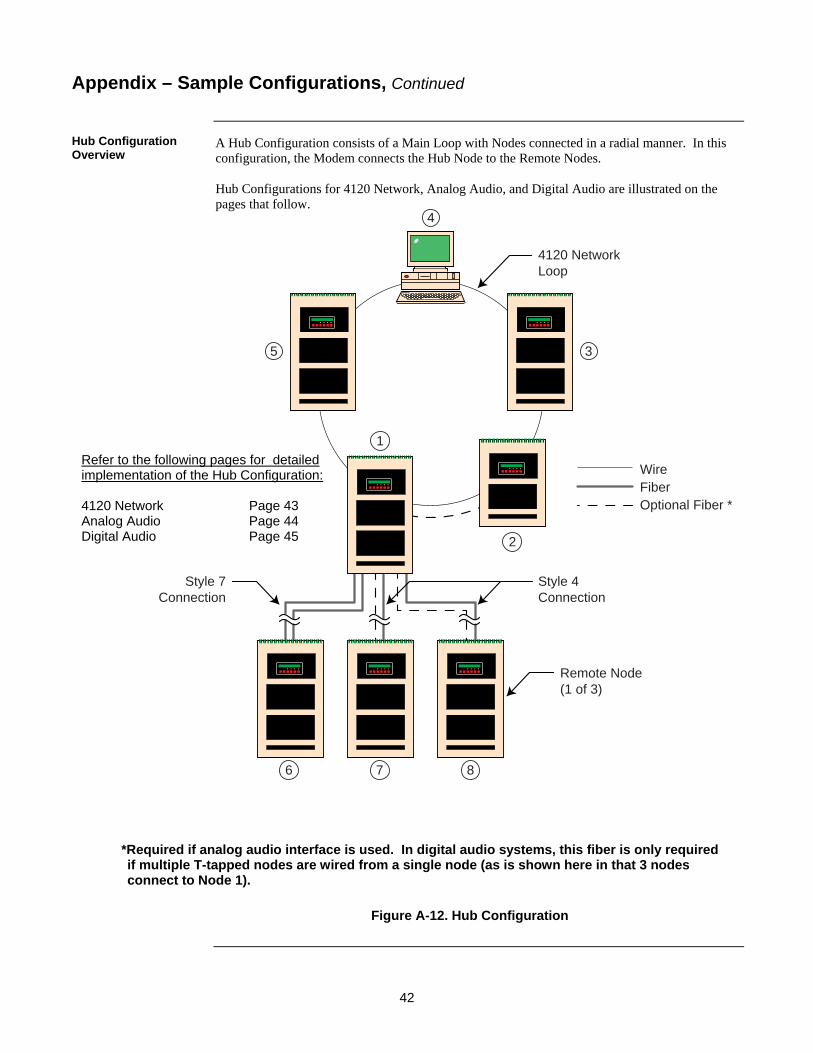
42
5 3
4
1
2
6 7 8
WireFiberOptional Fiber *
4120 NetworkLoop
Style 4Connection
Style 7Connection
Remote Node(1 of 3)
A Hub Configuration consists of a Main Loop with Nodes connected in a radial manner. In this configuration, the Modem connects the Hub Node to the Remote Nodes. Hub Configurations for 4120 Network, Analog Audio, and Digital Audio are illustrated on the pages that follow.
Figure A-12. Hub Configuration
Appendix – Sample Configurations, Continued
Hub Configuration Overview
*Required if analog audio interface is used. In digital audio systems, this fiber is only required if multiple T-tapped nodes are wired from a single node (as is shown here in that 3 nodes connect to Node 1).
Refer to the following pages for detailed implementation of the Hub Configuration: 4120 Network Page 43 Analog Audio Page 44 Digital Audio Page 45
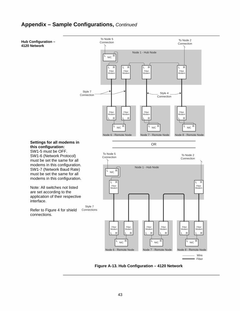
43
To Node 5Connection
Style 7Connection Style 4
Connection
OR
Node 1 - Hub Node
Node 6 - Remote Node Node 7 - Remote Node
To Node 2Connection
L RNIC
L RNIC
L RFiber
Modem
L R
FiberModem
L RFiber
Modem
L R
FiberModem
L RNIC
L RFiber
Modem
L R
FiberModem
Node 8 - Remote Node
L RNIC
L RFiber
Modem
L R
FiberModem
To Node 5Connection
Style 7Connections
Node 1 - Hub Node
Node 6 - Remote Node Node 7 - Remote Node
To Node 2Connection
L RNIC
L RNIC
L RFiber
Modem
L R
FiberModem
L R
FiberModem
L RNIC
L R
FiberModem
L R
FiberModem
L RNIC
L R
FiberModem
L R
FiberModem
Node 8 - Remote Node
WireFiber
L RFiber
Modem
Figure A-13. Hub Configuration – 4120 Network
Appendix – Sample Configurations, Continued
Hub Configuration – 4120 Network
Settings for all modems in this configuration: SW1-5 must be OFF. SW1-6 (Network Protocol) must be set the same for all modems in this configuration. SW1-7 (Network Baud Rate) must be set the same for all modems in this configuration. Note: All switches not listed are set according to the application of their respective interface. Refer to Figure 4 for shield connections.

44
To Node 5Connection
Node 1 - Hub Node
Node 6 - Remote Node
To Node 2Connection
(Fiber Modem)
PRI SECRIC
FiberModem
PRI SECRIC
FiberModem
AN
ALO
GA
NA
LOG
AN
ALO
G
FiberModem
Node 7 - Remote Node
PRI SECRIC
FiberModem
AN
ALO
G
AN
ALO
G
FiberModem
Node 8 - Remote Node
PRI SECRIC
FiberModem
AN
ALO
G
AN
ALO
G
FiberModem
WireFiber
Riser 1 setting:SW 2 -2 On
Riser 2 setting:SW 3 -2 On
Riser 1 setting:SW 2 -2 On
Riser 2 setting:SW 3 -2 On
Riser 1 setting:SW 2 -2 On
Riser 2 setting:SW 3 -2 On
Riser 1 setting:SW 2 -2 On
Riser 2 setting:SW 3-2 On
Riser 2 setting:SW 3 -2 Off
Riser 1 setting:SW 2 -2 Off
Riser 1 setting:SW 2 -2 Off
Riser 2 setting:SW 3 -2 Off
Riser 1 setting:SW 2 -2 Off
Riser 2 setting:SW 3 -2 Off
In this diagram, the head-end audio cabinet is not shown. If Class A is required, head and tail-end modems require x-link connections.
Figure A-14. Hub Configuration – Analog Audio
Appendix – Sample Configurations, Continued
Hub Configuration – Analog Audio
Settings for all modems in this configuration (assuming both channels in use): SW2-1 and 3-1 are ON (set for Class A wiring). SW2-3 and 3-3 are OFF (set as generic - all modems shown are generic). SW2-4 and 3-4 are OFF (these are ignored since the modems are generic). SW2-5 and 3-5 are ON (enable CH1 & CH2 interface). Notes: RIC: Analog Audio Riser Interface Card. SW2-2 is ON for modems that receive the analog riser. SW2-2 is OFF for modems that transmit the analog riser. Shields are to be connected at one end of each wiring link to either Earth or 24C as required. All switches not listed are set according to the application of their respective interface.

45
DAR
DAR
DAR
DAR
DAR
DAR
DAR
To Node 5Connection
Node 1 - Hub Node
Node 6 - Remote Node Node 7 - Remote Node
To Node 2Connection
(Fiber Modem)
PRI SECRIC
PRI SECRIC
DAR DAR DAR DAR DAR DAR
PRI SECRIC
PRI SECRIC
FiberModem
FiberModem
FiberModem
FiberModem
FiberModem
FiberModem
FiberModem
Node 8 - Remote Node
WireFiber
Figure A-15. Hub Configuration – Digital Audio
Appendix – Sample Configurations, Continued
Hub Configuration – Digital Audio
RIC: Digital Audio Riser Interface Card. SW2-8: ON (enable DAR interface).

46
1
3
2
12 10
13
11 9
4120 NetworkMain Loop #1
4
8
4120 NetworkSub Loop #2
WireFiberOptional Fiber *
Star Configuration
Interconnected Loop
67
5
In this configuration, the Fiber Modem connects the two Style 7 network loops (#1 & #2) in tandem. It also connects several remote nodes to the loop (star).
Figure A-16. Interconnected Loop and Star Configurations
Appendix – Sample Configurations, Continued
Interconnected Loop and Star Configurations – Overview
*Required if analog audio interface is used. In digital audio systems, this fiber is only required if multiple T-tapped nodes are wired from a single node.
Refer to the following pages for detailed implementation of the Interconnected Loop and Star Configuration: 4120 Network Page 47 Analog Audio Page 48 Digital Audio Page 49

47
To Node 2Connection
Node 5Connection
Node 6Connection
To Node 12Connection
Node 3
LR
NIC
LR
FiberM
odem
WireFiber
Node 4
Node 8
LR
FiberM
odem
L RFiber
Modem
LR
NIC
L RNIC
Node 9
L R
FiberModem
L RNIC
Node 10
L RFiber
Modem
L RNIC
Node 11
L R
FiberModem
L RNIC
Figure A-17. Interconnected Loop and Star Configurations – 4120 Network
Appendix – Sample Configurations, Continued
Interconnected Loop and Star Configurations –4120 Network
Settings for all modems in this configuration: SW1-5 must be OFF (enable network). SW1-6 (Network Protocol) must be set the same for all modems in this configuration SW1-7 (Network Baud Rate) must be set the same for all modems in this configuration Note: All switches not listed are set according to the application of their respective interface. Refer to Figure 4 for shield connections.

48
Analog Audio Wires (2/channel)Fiber
Node 12Connection
Node 6Connection
Node 10
PRI SECRIC
FiberModem
AN
ALO
G
FiberModem
AN
ALO
G
Node 11
PRI SECRIC
FiberModem
AN
ALO
G
FiberModem
AN
ALO
G
Node 3
PRI SECRIC
FiberModem
AN
ALO
G
FiberModem
AN
ALO
G
Node 4
PRI SECRIC
FiberModem
AN
ALO
G
FiberModem
AN
ALO
G
Node 8
PRI SECRIC
FiberModem
AN
ALO
G
FiberModem
AN
ALO
G
Node 9
PRI SECRIC
FiberModem
AN
ALO
G
FiberModem
AN
ALO
G
Riser 1 setting:SW 2-2 Off
Riser 2 setting:SW 3-2 Off
Riser 1 setting:SW 2-2 On
Riser 2 setting:SW 3-2 On
Riser 1 setting:SW 2-2 On
Riser 2 setting:SW 3-2 On
Riser 1 setting:SW 2-2 Off
Riser 2 setting:SW 3-2 Off
Riser 1 setting:SW 2-2 Off
Riser 2 setting:SW 3-2 Off
Riser 1 setting:SW 2-2 Off
Riser 2 setting:SW 3-2 Off
Riser 1 setting:SW 2-2 On
Riser 2 setting:SW 3-2 On
Riser 1 setting:SW 2-2 Off
Riser 2 setting:SW 3-2 Off
Riser 1 setting:SW 2-2 On
Riser 2 setting:SW 3-2 On
Riser 1 setting:SW 2-2 Off
Riser 2 setting:SW 3-2 Off
Riser 1 setting:SW 2-2 On
Riser 2 setting:SW 3-2 On
Riser 1 setting:SW 2-2 On
Riser 2 setting:SW 3-2 On
Figure A-18. Interconnected Loop and Star Configurations – Analog Audio
Appendix – Sample Configurations, Continued
Interconnected Loop and Star Configurations – Analog Audio
Settings for all modems in this configuration (assuming both channels in use): SW2-1 and 3-1 are OFF (set for Class B wiring). SW2-3 and 3-3 are OFF (set as generic - all modems shown are generic in Class B configuration). SW2-4 and 3-4 are OFF (these are ignored since the modems are generic). SW2-5 and 3-5 are ON (enable CH1 & CH2 interface). Notes: RIC: Analog Audio Riser Interface Card. SW2-2 and SW3-2 are ON for modems that receive the analog riser. SW2-2 and SW3-2 are OFF for modems that transmit the analog riser. Shields are to be connected at one end of each wiring link to either Earth or 24C as required. All switches not listed are set according to the application of their respective interface.

49
Node 10
Node 6Connection
PRI SEC2SEC1RIC
FiberModem
DAR
DAR Wires (2)Fiber
Node 3 Node 4
Node 8
Node 9
PRI SEC2SEC1RIC
PRI SEC2SEC1RIC
PRI SEC2SEC1RIC
PRI SEC2SEC1RIC
FiberModem
DAR
FiberModem
DAR
FiberModem
DAR
FiberModem
DAR
Node 11
PRI SEC2SEC1RIC
FiberModem
DAR
Node 12Connection
Figure A-19. Interconnected Loop and Star Configurations – Digital Audio
Appendix – Sample Configurations, Continued
Interconnected Loop and Star Configurations – Digital Audio
Settings for all modems in this configuration: SW2-8 is ON for all modems in this example (enable DAR). Notes: RIC: Digital Audio Riser Interface Card. All switches not listed are set according to the application of their respective interface.

50
3
6
1
2
4 5
Node 2
Node 1
L R
L R
NIC
FiberModem
L R
FiberModem
Node 3
L R
L R
NIC
FiberModem
L R
FiberModem
WireFiber
Node 4
L R
L R
NIC
FiberModem
L R
FiberModem
Node 5
L R
L R
NIC
FiberModem
L R
FiberModem
Node 6
L R
L R
NIC
FiberModem
L R
FiberModem
The illustration below shows how to connect the 4120 Network to IMS with fiber only. Node 1 is used for power and an enclosure is used for the Modems.
Figure A-20. Fiber-Connected IMS Configuration
Appendix – Sample Configurations, Continued
TrueSite Workstation (TSW)
Notes: Node 1 provides power and a cabinet for the modems connected to the IMS. Optionally, replace Node 1 with a transponder cabinet and connect additional modems to wire RUI to the transponder.
Settings for all modems in this configuration: SW1-5 must be OFF. SW1-6 (Network Protocol) must be set the same for all modems in this configuration SW1-7 (Network Baud Rate) must be set the same for all modems in this configuration Note: All switches not listed are set according to the
application of their respective interface. Refer to Figure 4 for shield connections.

51
FIBER MODEM /EXPN BD
ENCLOSURE
4100U
CLOSE NIPPLED WIRING
4100
*Required for Class A installations
WireFiberOptional Fiber *
4100 Fiber Modem expansion cabinet
4100U
ModemExp Hdr
FIBE
R
ModemExp Hdr
FIBE
R
ModemExp Hdr
FIBE
R
AMP
RIS
ER
SIGNAL
NA
C1 - B
NA
C1 - A
NA
C2 - B
NA
C2 - A
SIG
IN
RIS
ER
1
RIS
ER
1
RIS
ER
2
RIS
ER
2
R1 - X
LINK
R1 - X
LINK
R2 - X
LINK
R2 - X
LINK
RIS
ER
1-OU
TR
ISE
R2-O
UT
Audio InputOptionCard
IN
AudioController
Harness
IN
4100 AudioExp
ModemExp Hdr
FIBE
R
RIS
ER
1
RIS
ER
1
RIS
ER
2
RIS
ER
2
R1 - X
LINK
R1 - X
LINK
R2 - X
LINK
R2 - X
LINK
RIS
ER
1-OU
TR
ISE
R2-O
UT
4100 AudioExp
R2-X
LINK
RIS
ER
2
R1-X
LINK
RIS
ER
1
R2-X
LINK
RIS
ER
2
R1-X
LINK
RIS
ER
1
Figure A-21. Fiber Modem Audio Expansion Board, Class A/Style 6 (4100U Shown)
Appendix – Sample Configurations, Continued
Fiber Modem Audio Expansion Board Class A/Style 6

52
4100 Fiber Modem expansion cabinet
4100U
ModemExp Hdr
FIBE
R
ModemExp Hdr
FIBE
R
AMP
RIS
ER
SIGNAL
NA
C1 - B
NA
C1 - A
NA
C2 - B
NA
C2 - A
SIG
IN
RIS
ER
1
RIS
ER
1
RIS
ER
2
RIS
ER
2
R1 - X
LINK
R1 - X
LINK
R2 - X
LINK
R2 - X
LINK
RIS
ER
1-OU
TR
ISE
R2-O
UT
Audio InputOptionCard
IN R2-X
LINK
RIS
ER
2
R1-X
LINK
RIS
ER
1
AudioController
Harness
IN
4100 AudioExp
Figure A-22. Fiber Modem Audio Expansion Board, Class B/Style 4 (4100U Shown)
Appendix – Sample Configurations, Continued
Fiber Modem Audio Expansion Board Class B/Style 4


© 2006 - 2011 SimplexGrinnell LP. Specifications and other information were current as of publication and are subject to change without notice.
579-831 Rev. H