feedrate optimization in 5-axis machining based on direct
TRANSCRIPT

HAL Id: hal-01064136https://hal.archives-ouvertes.fr/hal-01064136
Submitted on 15 Sep 2014
HAL is a multi-disciplinary open accessarchive for the deposit and dissemination of sci-entific research documents, whether they are pub-lished or not. The documents may come fromteaching and research institutions in France orabroad, or from public or private research centers.
L’archive ouverte pluridisciplinaire HAL, estdestinée au dépôt et à la diffusion de documentsscientifiques de niveau recherche, publiés ou non,émanant des établissements d’enseignement et derecherche français ou étrangers, des laboratoirespublics ou privés.
Feedrate optimization in 5-axis machining based ondirect trajectory interpolation on the surface using an
open cncXavier Beudaert, Sylvain Lavernhe, Christophe Tournier
To cite this version:Xavier Beudaert, Sylvain Lavernhe, Christophe Tournier. Feedrate optimization in 5-axis machin-ing based on direct trajectory interpolation on the surface using an open cnc. 11th InternationalConference on High Speed Machining, Sep 2014, Prague, Czech Republic. paper n. 14042, 6 p.�hal-01064136�

ISBN 978-80-904077-7-0
Proceedings of the 11th International Conference on High Speed Machining September 11-12, 2014, Prague, Czech Republic
HSM2014-14042
FEEDRATE OPTIMIZATION IN 5-AXIS MACHINING BASED ON DIRECT TRAJECTORY INTERPOLATION ON THE SURFACE
USING AN OPEN CNC X. Beudaert1, S.Lavernhe1*, C. Tournier1
1LURPA, ENS Cachan, Université Paris Sud, Cachan, France
*Corresponding author; e-mail: [email protected]
Abstract In the common machining process of free-form surfaces, CAM software generates approximated tool paths because of the input tool path format of the industrial CNC. Then, marks on finished surfaces may appear due to non smooth feedrate planning during interpolation. The Direct Trajectory Interpolation on the Surface (DTIS) method allows managing the tool path geometry and the kinematical parameters to achieve higher productivity and a better surface quality. Machining experiments carried out with an Open CNC on a 5-axis high speed milling machine show the benefits of the proposed method compare to the classical strategies available with an industrial CNC. Keywords: 5-axis machining; open CNC; surface interpolation; maximum feedrate; jerk
1 INTRODUCTION 3 and 5-axis High Speed Milling machines are often used to generate free-form surfaces for mold and die, aeronautical or biomedical industries. However, 3 and 5-axis machining strategies encounter the same problems concerning the linear discretization of the tool path which reduces the performance of the machining process. Indeed, the linear interpolation (G1) is the most commonly used format to describe the tool paths in current industrial CNCs. However, the G1 discretization brings several major drawbacks:
Chordal deviations between the ideal tool path and the discretized one in CAM software by the use of a machining tolerance,
‘Orange skin effect’ or facets may appear on the machined surface,
Huge amount of data required to describe a simple parametric curve,
Reduction of the feedrate because of the block processing time of the CNC,
Tangency discontinuities between the segments, which limits the maximum reachable feedrate.
In the literature, several propositions have been made to improve the manufacturing process of free-form surfaces. Three approaches can be distinguished: tool path smoothing, native polynomial interpolation and direct interpolation on the surface.
CNC tool path smoothing techniques have been presented in the literature to round the discontinuities created by the linear interpolation. A cubic B-Spline is used in [Pateloup
2010] to round 3-axis G1 or in [Beudaert 2013] to round 3 and 5-axis discontinuities whereas a quartic polynomial curve is proposed in [Erkorkmaz 2006]. CNC builders also developed efficient algorithms for corner rounding [Yutkowitz 2005] or online spline interpolation with compressor functions to smooth the entire tool path [Siemens 2009][Otsuki 2004]. These methods combined with look ahead strategies reduce the effects of the G1 discontinuities but their performances are limited by the real-time constraint. Furthermore, a CNC tolerance is required which induces again geometrical deviations between the tool path and the surface to be machined.
Advanced CAM and CNC systems such as Catia v5 and Siemens 840D can allow a native B-Spline interpolation. The NC code sent to the numerical controller contains the mathematical expression of the B-Spline curves representing the tool path. Algorithms to generate native cubic B-Spline tool path in 3 and 5-axis to improve the surface quality while reducing the amount of data are proposed in [Lartigue 2001][Langeron 2004][Chen 2013]. The native B-Spline interpolation is the best solution currently available to get a smooth tool path with high productivity and improved surface finish.
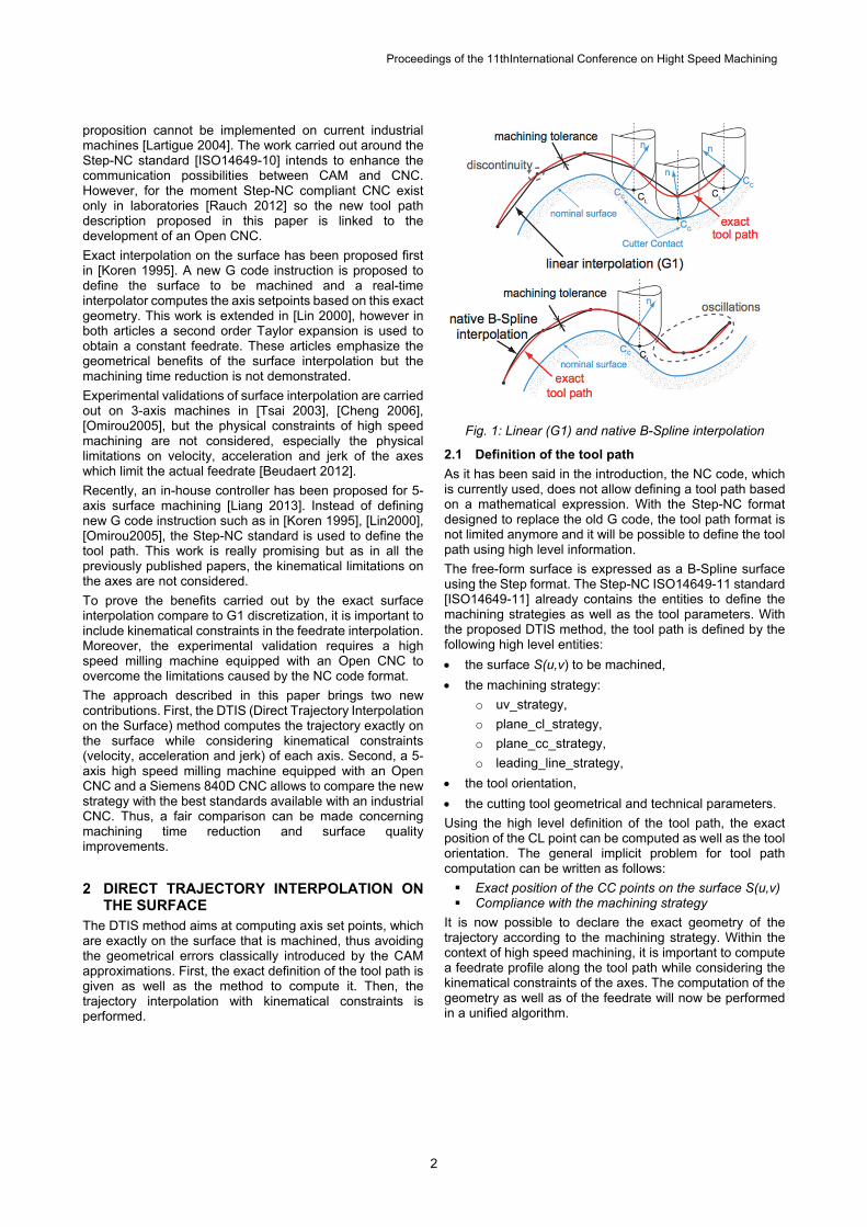
No matter which previously cited strategy is used, the CAM tool path sent to the CNC is an approximation of the exact tool path. The result is that the CAM tool path is oscillating around the exact tool path, which reduces the smoothness and induces geometrical errors (Fig.1).
Thus, the third option is to use the exact tool path geometry instead of an approximation. This option should obviously be preferred but as the NC code interpreted by industrial CNCs is really limited in terms of geometrical entities, this
Proceedings of the 11thInternational Conference on Hight Speed Machining
2
proposition cannot be implemented on current industrial machines [Lartigue 2004]. The work carried out around the Step-NC standard [ISO14649-10] intends to enhance the communication possibilities between CAM and CNC. However, for the moment Step-NC compliant CNC exist only in laboratories [Rauch 2012] so the new tool path description proposed in this paper is linked to the development of an Open CNC.
Exact interpolation on the surface has been proposed first in [Koren 1995]. A new G code instruction is proposed to define the surface to be machined and a real-time interpolator computes the axis setpoints based on this exact geometry. This work is extended in [Lin 2000], however in both articles a second order Taylor expansion is used to obtain a constant feedrate. These articles emphasize the geometrical benefits of the surface interpolation but the machining time reduction is not demonstrated.
Experimental validations of surface interpolation are carried out on 3-axis machines in [Tsai 2003], [Cheng 2006], [Omirou2005], but the physical constraints of high speed machining are not considered, especially the physical limitations on velocity, acceleration and jerk of the axes which limit the actual feedrate [Beudaert 2012].
Recently, an in-house controller has been proposed for 5-axis surface machining [Liang 2013]. Instead of defining new G code instruction such as in [Koren 1995], [Lin2000], [Omirou2005], the Step-NC standard is used to define the tool path. This work is really promising but as in all the previously published papers, the kinematical limitations on the axes are not considered.
To prove the benefits carried out by the exact surface interpolation compare to G1 discretization, it is important to include kinematical constraints in the feedrate interpolation. Moreover, the experimental validation requires a high speed milling machine equipped with an Open CNC to overcome the limitations caused by the NC code format.
The approach described in this paper brings two new contributions. First, the DTIS (Direct Trajectory Interpolation on the Surface) method computes the trajectory exactly on the surface while considering kinematical constraints (velocity, acceleration and jerk) of each axis. Second, a 5-axis high speed milling machine equipped with an Open CNC and a Siemens 840D CNC allows to compare the new strategy with the best standards available with an industrial CNC. Thus, a fair comparison can be made concerning machining time reduction and surface quality improvements.
2 DIRECT TRAJECTORY INTERPOLATION ON THE SURFACE
The DTIS method aims at computing axis set points, which are exactly on the surface that is machined, thus avoiding the geometrical errors classically introduced by the CAM approximations. First, the exact definition of the tool path is given as well as the method to compute it. Then, the trajectory interpolation with kinematical constraints is performed.
Fig. 1: Linear (G1) and native B-Spline interpolation
2.1 Definition of the tool path
As it has been said in the introduction, the NC code, which is currently used, does not allow defining a tool path based on a mathematical expression. With the Step-NC format designed to replace the old G code, the tool path format is not limited anymore and it will be possible to define the tool path using high level information.
The free-form surface is expressed as a B-Spline surface using the Step format. The Step-NC ISO14649-11 standard [ISO14649-11] already contains the entities to define the machining strategies as well as the tool parameters. With the proposed DTIS method, the tool path is defined by the following high level entities:
the surface S(u,v) to be machined,
the machining strategy:
o uv_strategy,
o plane_cl_strategy,
o plane_cc_strategy,
o leading_line_strategy,
the tool orientation,
the cutting tool geometrical and technical parameters.
Using the high level definition of the tool path, the exact position of the CL point can be computed as well as the tool orientation. The general implicit problem for tool path computation can be written as follows:
Exact position of the CC points on the surface S(u,v) Compliance with the machining strategy
It is now possible to declare the exact geometry of the trajectory according to the machining strategy. Within the context of high speed machining, it is important to compute a feedrate profile along the tool path while considering the kinematical constraints of the axes. The computation of the geometry as well as of the feedrate will now be performed in a unified algorithm.

Proceedings of the 11thInternational Conference on Hight Speed Machining
3
2.2 DTIS principle
Each drive has its own kinematical limits in terms of velocity, acceleration and jerk. The role of the feedrate interpolator is to create the motion law respecting all the kinematical constraints along the tool path and especially the axis jerk. The axis jerk often limits the actual feedrate and it is an important parameter to avoid excessive vibrations in high speed machining.
This section will show how the DTIS method can merge, in a unique scheme, tool path computation and feedrate interpolation. The feedrate interpolation is based on the Velocity Profile Optimization algorithm (VPOp) previously developed [Beudaert 2012].
The DTIS method is composed of three main loops (Fig.2)
1. Computation of next cutter location with maximal feedrate under kinematical constraints:
o The main loop (in blue) is the trajectory interpolation: it consists in computing new tool positioning from previous ones while verifying kinematical constraints.
2. Local feedrate reduction to respect axes kinematical constraints:
o When axis kinematical constraints are not satisfied by the initial tool positioning, the second loop (in orange) modify the local feedrate by estimating an admissible domain along the trajectory.
3. Backward modification of previous cutter location with maximum deceleration until respect of kinematical constraints:
o The third loop (in purple) deals with situations where no admissible solution can be found (empty interval). Typically, on portion of tool paths with high curvature, it’s necessary to reduce feedrate before entering the curve. If the feedrate is too high at the entrance of a high curvature area, a backward scan is performed to find the point from which it is necessary to decelerate.
The main contribution of the proposed DTIS method is to use the exact tool path definition and to respect the kinematical constraints.
2.3 Tool path interpolation
The tool path interpolation is performed directly into the parametric space of the surface to cancel errors from tool positioning. Moreover with DTIS method, since there is no more association of linear or polynomial format, all computed setpoints are by definition exactly on the surface without chord error.
To solve the implicit problem of tool path computation with "plane_cl_strategy", a Newton-Raphson method is illustrated in Fig. 3. Starting from the point (u,v) of the machined surface, the first guest (u0,v0) is computed assuming an evolution with maximum productivity (distance s). Then, the errors Ɛ1 and Ɛ2 are minimized to compute the next point (u*,v*) on the tool path according to the machining strategy.
As the machined surface is usually really smooth, the first guess is really close to the exact value, only one or two iterations can be necessary to set the tool positioning with an error under 0.001 µm. Such a threshold is negligible for high speed machining applications. Thus with this iterative method, the tool path can be computed exactly on the surface.
Fig. 2: DTIS principle
Fig. 3: Exact tool path computation

Proceedings of the 11thInternational Conference on Hight Speed Machining
4
2.4 Kinematical constraints from the tool path
The interpolation of the tool path is based on the estimation of the feedrate profile. Indeed, from the previous tool positionings (uj-2,vj-2), (uj-1,vj-1), (uj,vj) and their positions on the trajectory (sj-2, sj-1, sj) the feedrate profile is defined with the tangential kinematical constraints Vfmax, Atan
max, Jtanmax,.
Considering that maximal and minimal constraints are symmetrical and the fixed temporal step size t of the interpolator cycle time, it is possible to determine the admissible domain of the tool path for sj-1. Hence, the corresponding spatial step (s) on the trajectory is used during the interpolation stage to set the new tool positioning (u*,v*) with s = sj+1-sj. To maximize the efficiency of machining and the productivity, the farthest point is chosen by default (sj+1=s1
max).
2.5 Kinematical constraints from the machine tool axes
Once the interpolation stage is performed, kinematical solicitations on each axis resulting from the previous tool positionings are compared to the axis constraints. Kinematical solicitations are evaluated exactly since tool positionings are previously evaluated using the CAD model and the inverse kinematical transformation of the machine tool are known. One can find more details on the equations of kinematical characteristics in [Beudaert 2012].
If constraints are satisfied, the current tool positioning is validated and the algorithm goes to next iteration. If not, the first stage is to locally modify the current tool positioning to respect axis constraints (orange loop on Fig.2). On the first tool positioning, axis constraints are used to evaluate the admissible domain ([s2
min, s2max]). This domain can then be
intersected with the domain n°1 to find a new tool position sj+1 and continue the main loop by the Newton-Raphson refinement.
Sometimes, when feedrate needs to be decreased, the intersection of admissible domains n°1 and n°2 is empty. Hence, within the purple loop, previous tool positionings are modified. An iterative backward research allows to find a minimal sequence of setpoints to decelerate and reach the admissible kinematical level to respect constraints. To do so, the lower bound of the admissible domains intersection is selected: criterium of maximum feedrate increase is switched to maximum feedrate decrease. This method goes then backward to modify previous computed points until tool positioning of index j is solved. The efficiency of the iterative research can be notably improved by using a dichotomy principle and look ahead anticipation [Beudaert 2012].
3 APPLICATION 3.1 PREMIUM-OpenCNC
As it has been said in the introduction, the exact surface interpolation cannot be performed using an industrial CNC. Thus, it is necessary to develop an Open CNC in order to overcome the limitations of the NC code and to control directly the movements of the machine.
The PREMIUM-OpenCNC (Fig.4) has been developed to control the motion of a 5-axis Mikron UCP710 high speed milling machine originally equipped with the Siemens 840D CNC. To reduce the development efforts, the Siemens 840D is not totally disconnected. Indeed, the Siemens CNC is still used for auxiliary tasks (cooling system, safety, PLC behavior...) and to control the spindle. However, it does not have any connection with the displacement axes, which are completely controlled by the PREMIUM-OpenCNC. An
interesting advantage of the hybrid solution used is that the same machine can be controlled with a Siemens 840D CNC and with an Open CNC, hence fair comparisons can be made to demonstrate the benefits of the Direct Trajectory Interpolation on the Surface.
Fig. 4: 5-axis high speed milling machine with the PREMIUM-OpenCNC and the Siemens 840D CNC
3.2 Test case
The DTIS method is applied on a 5-axis tool path (Fig.5). An aluminum workpiece is machined with a bull nose cutter with 5 different strategies (Tab.1). The programmed feedrate Vf is 3m/min. For each strategy, the tilt angle is fixed at 10 deg with no yaw angle, which produces a 5-axis tool path with a simultaneous movement of Y, Z and A axes along one path. As the surface is ruled in the X direction, one pass in the YZ plane is repeated with a step over distance of 2 mm to machine the surface. The tool path lays in a plane, so it is easier to measure and to represent the effect of the tool path format on the feedrate.
Tab. 1: Machining strategies
Fig. 5: 5-axis tool path with 10 deg tilt angle
The first two strategies use the most popular format which is the linear interpolation (G1) with two different CAM tolerances, 10 µm and 1 µm respectively. In Tab.1, the number of NC blocks used to describe one pass is collected as well as the machining time. With a higher CAM tolerance, the amount of data is reduced but it is important to notice that the machining time is increased. There is no direct connection between the machining
Strategy CNC NC blck
Time (s)
G1 10µm 840D 59 14.4
G1 1µm 840D 189 12.2
B-Spline 10µm 840D 85 8
B-Spline 1µm 840D 226 9
DTIS OpenCNC - 3

Proceedings of the 11thInternational Conference on Hight Speed Machining
5
time and the number of blocks, depending on the angles between the segments the feedrate variation is changing as pointed out in [Beudaert2012].
The strategies 3 and 4 use the native B-Spline format generated with Catia V5 CAM software and interpreted directly by the Siemens 840D CNC. Here also two different CAM tolerances are tested. A tolerance of 10 µm is standard for general purpose curve interpolation, with 1 µm the chord error is really small for precise finishing operations. This native B-Spline interpolation is the best solution industrially available for free-form surface machining. Indeed, a continuous B-Spline tool path is created by the CAM software so the CNC does not have to run complex smoothing algorithms in real-time. As the tool path geometry is smoother than with a G1 tool path smoothed by the CNC, the machining time is reduced.
The last portion of the workpiece is machined with the newly developed DTIS method. For this surface, the DTIS algorithm performs both tool positionings and feedrate interpolation in a synchronous manner with the PREMIUM-OpenCNC. As there is no discretization of the tool path, the number of blocks is meaningless for this strategy because cutter locations are computed during the interpolation on a portion of the trajectory. The machining time is reduced by more than twice compare to the best industrial solution, i.e. the native B-Spline interpolation and by more than four times compare to the commonly used G1 format. This machining time reduction is explained by the better tool path smoothness obtained with the direct interpolation on the surface. The reason for this difference of smoothness between the DTIS tool path and the B-Spline tool path is quite clear. As the B-Spline tool paths are approximated, they are oscillating around the theoretical curve which is the smoothest tool path.
The measured feedrates are presented in Fig.6. For the G1 10 µm strategy, it is clear that the feedrate have strong oscillations along the path. The discontinuities at the end of each NC block induce feedrate slowdowns. With the second strategy G1 1 µm, the discontinuities are reduced so as the feedrate variations. For the B-Spline strategies, the tool path is smoother so the feedrate profile is also smoother. However, the programmed feedrate of 3m/min is never reached with the industrial strategies. The DTIS strategy allows to significantly increase the feedrate and even to reach the programmed feedrate at the end of the tool path. At the beginning, the programmed feedrate cannot be reached because of the acceleration and jerk limitations of the A axis which is highly excited.
Fig. 6: Measured feedrate as a function of time for the 5 strategies
The feedrate profiles presented in the previous figure are plotted on top of the tool path geometry in Fig.7. As it is a 5-axis tool path, the analysis of the feedrate reduction is difficult because it is not directly linked to the curvature of the tool path. However, for the first strategy, the feedrate oscillations correspond to the programmed position and orientation of the G1 NC blocks. Around Y=20mm, there is a long segment where the feedrate is higher but this important variation of feedrate is harmful for the surface finish. On the second graph for G1 1 µm, one can see that the feedrate is not linked to the NC block density. With native B-Spline strategies, the feedrate is everywhere higher than with the G1 strategies. However, low feedrate in dark blue is still present all along the tool path. Finally, with the DTIS method the feedrate is quite high all along the tool path without sharp oscillation. A feedrate reduction appear just before Y=20mm because of a rapid movement of the A axis caused by the rapid change of tool orientation. Fig.7 shows that the feedrate is changing all along the tool path and sharp feedrate variations may leave marks on the machined surface.
4 SUMMARY The application presented in this paper clearly shows the benefits of the Direct Trajectory Interpolation on the Surface in terms of productivity. Thanks to the experimental validation on a 5-axis high speed machine and the comparison between the industrial strategies and the proposed method, it has been demonstrated that the machining time can be divided by a factor between 2 and 4 compared with G1 and native B-Spline interpolations. As it is demonstrated in this paper, the amelioration of the data exchange between CAD/CAM and CNC will open new ways to optimize the manufacturing process.

Proceedings of the 11thInternational Conference on Hight Speed Machining
6
5 ACKNOWLEDGMENTS This work is supported by the French Ministry of Research and the Digiteo foundation (2010-47D).
Fig. 7: Representation of the feedrate on the geometry for the 5 strategies
6 REFERENCES [Beudaert 2012] Beudaert, X., Lavernhe, S., Tournier, C., Feedrate interpolation with axis jerk constraints on 5-axis NURBS and G1 tool path. International Journal of Machine Tools and Manufacture, 2012, Vol.57, pp 73-82.
[Beudaert 2013] Beudaert, X., Lavernhe, S., Tournier, C., 5-axis local corner rounding of linear tool path discontinuities. International Journal of Machine Tools and Manufacture, 2013, Vol.73, pp 9-16.
[Cheng 2006] C.-W. Cheng, W.-P. Tseng, Design and implementation of a real-time NURBS surface interpolator. The International Journal of Advanced Manufacturing Technology, 2006, Vol.30, pp 98-104.
[Chen 2014] Chen, Z.C., Khan, M.A., A new approach to generating arc length parameterized NURBS tool paths for efficient three-axis machining of smooth, accurate
sculptured surfaces. The International Journal of Advanced Manufacturing Technology, 2014, Vol.70, pp 1355-1368.
[Erkorkmaz 2006] Erkorkmaz, K. Yeung, C.-H., Altintas, Y., Virtual CNC system. Part II. High speed contouring application. International Journal of Machine Tools and Manufacture, 2006, Vol.46, No.10, pp 1124-1138.
[ISO14649-10] ISO14649-10 Industrial automation systems and integration - Physical device control - Data model for computerized numerical controllers - Part 10: General process data, 2004.
[ISO14649-11] ISO14649-11 Industrial automation systems and integration - Physical device control - Data model for computerized numerical controllers - Part 11: Process data for milling, 2004.
[Koren1995] Koren, Y., Lin, R.-S., Five-Axis Surface Interpolators. CIRP Annals - Manufacturing Technology, 1995, Vol.44, No.1, pp 379-382.
[Langeron 2004] Langeron, J-M., Duc, E., Lartigue, C., Bourdet, P.,A new format for 5-axis tool-path computation, using B-spline curves. Computer-Aider Design, 2004, Vol.36, No.12, pp 1219-1229.
[Lartigue 2001] Lartigue, C., Thiebaut, F., Maekawa, T., CNC tool path in terms of B-spline curves. Computer-Aided Design, 2001, Vol.33, No.4, pp 307-319.
[Lartigue 2004] Lartigue, C., Tournier, C., Ritou, M., Dumur, D., High-Performance NC for HSM by means of Polynomial Trajectories. CIRP Annals - Manufacturing Technology, 2004, Vol.53, No.1, pp 317-320.
[Liang 2013] Liang, H., Li, X., Five-axis STEP-NC controller for machining of surfaces. The International Journal of Advanced Manufacturing Technology, 2013, Vol.68, No.9-12, pp 2791-2800.
[Lin2000] Lin, R.-S., Real-time surface interpolator for 3D parametric surface machining on 3-axis machine tools. International Journal of Machine Tools and Manufacture, 2000, Vol.40, No.10, pp 1513-1526.
[Omirou2005] Omirou, S. L., Barouni, A. K. Integration of new programming capabilities into a CNC milling system. Robotics and Computer-Integrated Manufacturing, 2005, Vol.21, No.6, pp 518-527.
[Otsuki 2004] Otsuki, T., Ogino, H., Ide, S., Chiba, T., Curve interpolation method, Japan, Fanuc LTD. Yamanashi (US Patent 6823234 B2), 2004.
[Pateloup 2010] Pateloup, V., Duc, E., Ray P., Bspline approximation of circle arc and straight line for pocket machining. Computer-Aided Design, 2010, Vol.42, No.9, pp 817-827.
[Rauch 2012] Rauch, M., Laguionie, R., Hascoet, J-Y., Suh, S-H., Advanced STEP-NC controller for intelligent machining processes. Robotics and Computer-Integrated Manufacturing, 2012, Vol.28, No.3, pp 375-384.
[Siemens 2009] Siemens, Sinumerik - 5 axis machining, DocOrderNo. 6FC5095-0AB10-0BP1, 2009.
[Tsai 2003] Tsai, M. C., Cheng, C. W., Cheng, M. Y. A real-time NURBS surface interpolator for precision three-axis CNC machining. International Journal of Machine Tools and Manufacture, 2003, Vol.43, No.12, pp 1217-1227.
[Yutkowitz 2005] Yutkowitz, S.J., Chester, W., Apparatus and method for smooth cornering in a motion control system, United States, Siemens Energy & Automation, Inc. Alpharetta, GA (US Patent 6922606), 2005.