feedback amplifier stability
DESCRIPTION
Feedback Amplifier Stability. Feedback analysis Midband gain with feedback New low and high 3dB frequencies Modified input and output resistances, e.g. Amplifier’s frequency characteristics Feedback amplifier’s gain Define Loop Gain as β f A Magnitude Phase. A( ). A o. A fo. - PowerPoint PPT PresentationTRANSCRIPT
Ch. 8 Feedback – Part 5 1ECES 352 Winter 2007
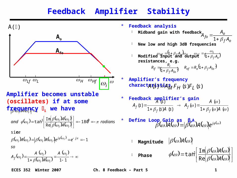
Feedback Amplifier Stability
* Feedback analysis Midband gain with feedback
New low and high 3dB frequencies
Modified input and output resistances, e.g.
* Amplifier’s frequency characteristics
* Feedback amplifier’s gain
* Define Loop Gain as βfA
Magnitude
Phase
)()(1
)()(
)()(1
)()(
A
AA
sAs
sAsA
ff
ff
of
ofo A
AA
1
of
LLfHofHf A
A
11
'1'1 Iofoof
Iof
iif ARR
A
RR
A()
Ao
H HfLf L
Afo
)()()( sFsFAsA LHM
A
A
A
Re
Imtan 1
111
1
sin
180Re
Imtan
1
01
i
ii
iif
jjiiii
ii
iii
ii
A
A
AA
so
eeAA
ce
radiansA
Aand
A
i
Amplifier becomes unstable (oscillates) if at some frequency i we have
i
jeAA
Ch. 8 Feedback – Part 5 2ECES 352 Winter 2007
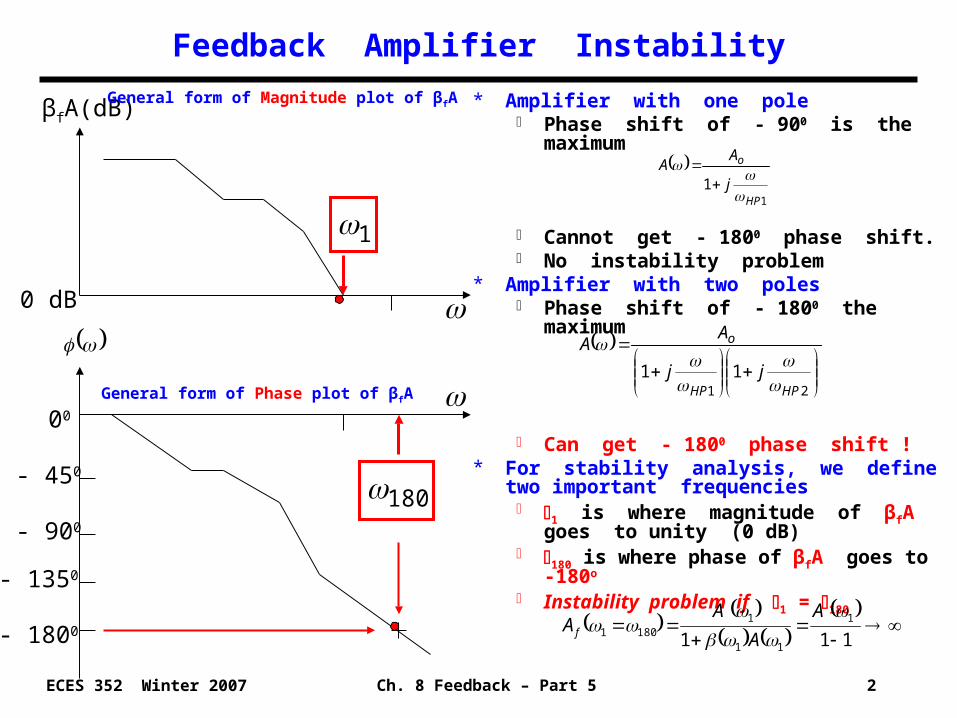
* Amplifier with one pole Phase shift of - 900 is the maximum
Cannot get - 1800 phase shift. No instability problem
* Amplifier with two poles Phase shift of - 1800 the maximum
Can get - 1800 phase shift !* For stability analysis, we define two
important frequencies 1 is where magnitude of βfA goes to
unity (0 dB) 180 is where phase of βfA goes to -180o Instability problem if 1 = 180
Feedback Amplifier Instability
βfA(dB)
0 dB
1
00
- 450
- 900
- 1350
- 1800
180
11
HP
o
j
AA
2111
HPHP
o
jj
AA
1111
11
11801
A
A
AAf
General form of Magnitude plot of βfA
General form of Phase plot of βfA
Ch. 8 Feedback – Part 5 3ECES 352 Winter 2007
Gain and Phase Margins
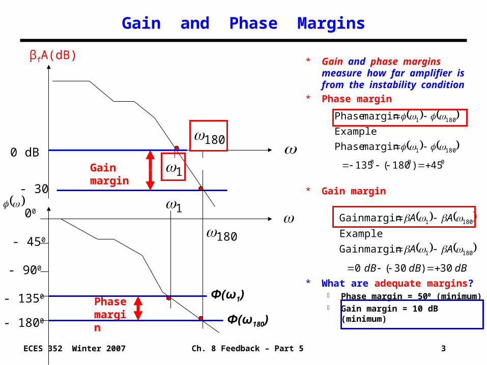
* Gain and phase margins measure how far amplifier is from the instability condition
* Phase margin
* Gain margin
* What are adequate margins? Phase margin = 500 (minimum) Gain margin = 10 dB (minimum)
0 dB
00
- 450
- 900
βfA(dB)
- 1350
- 1800
Phase margin
Gain margin
000
1801
1801
45)180(135
margin Phase
Example
margin Phase
dBdBdB
AA
AA
30)30(0
margin Gain
Example
margin Gain
1801
1801
1801
- 30
1
180
Φ(ω1)
Φ(ω180)
Ch. 8 Feedback – Part 5 4ECES 352 Winter 2007
Numerical Example - Gain and Phase Margins
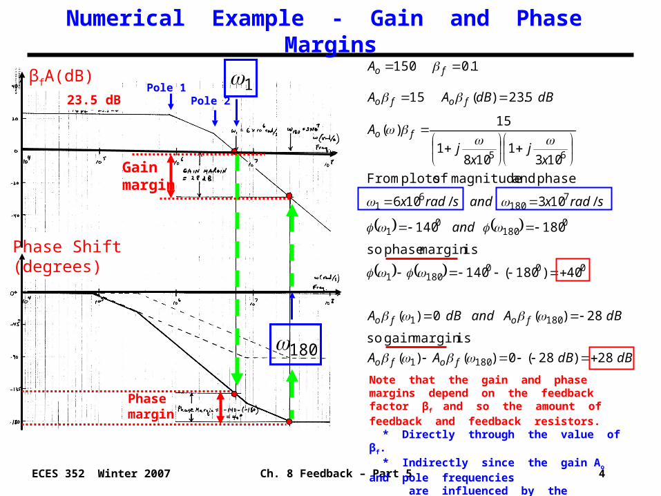
dBdBAA
dBAanddBA
and
sradxandsradx
xj
xj
A
dBdBAA
A
fofo
fofo
fo
fofo
fo
28)28(0)()(
ismargin gain so
28)(0)(
40)180(140
ismargin phase so
180140
/103/106
phase and magnitude of plots From
1031
1081
15)(
5.23)(15
1.0150
1801
1801
0001801
0180
01
7180
61
65
Phase margin
Gain margin
1
180
βfA(dB)
Phase Shift (degrees)
Note that the gain and phase margins depend on the feedback factor βf and so the amount of feedback and feedback resistors. * Directly through the value of βf. * Indirectly since the gain Ao and pole frequencies are influenced by the feedback resistors, e.g. the loading effects analyzed previously.
Pole 1Pole 223.5 dB
Ch. 8 Feedback – Part 5 5ECES 352 Winter 2007
Amplifier Design for Adequate Gain and Phase Margins
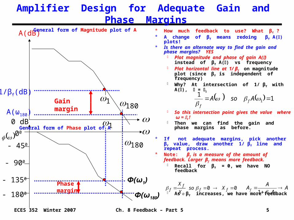
* How much feedback to use? What βf ?* A change of βf means redoing βf A() plots!* Is there an alternate way to find the gain and
phase margins? YES Plot magnitude and phase of gain A()
instead of βf A() vs frequency Plot horizontal line at 1/ βf on magnitude plot
(since βf is independent of frequency) Why? At intersection of 1/ βf with A(), = 1
So this intersection point gives the value where ω = 1 !
Then we can find the gain and phase margins as before.
* If not adequate margins, pick another βf value, draw another 1/ βf line and repeat process.
* Note: βf is a measure of the amount of feedback. Larger βf means more feedback.
Recall for βf = 0, we have NO feedback
As βf increases, we have more feedback00 ff
o
ff Xso
X
X
11
1
AsoA ff
1
00
- 450
- 900
180
Phase margin
Gain margin 180
1
A(dB)
- 1350
- 1800
1/βf(dB)
0 dB
General form of Magnitude plot of A
General form of Phase plot of A
AA
AA
ff
1
A(ω180)
Φ(ω1)
Φ(ω180)
Ch. 8 Feedback – Part 5 6ECES 352 Winter 2007
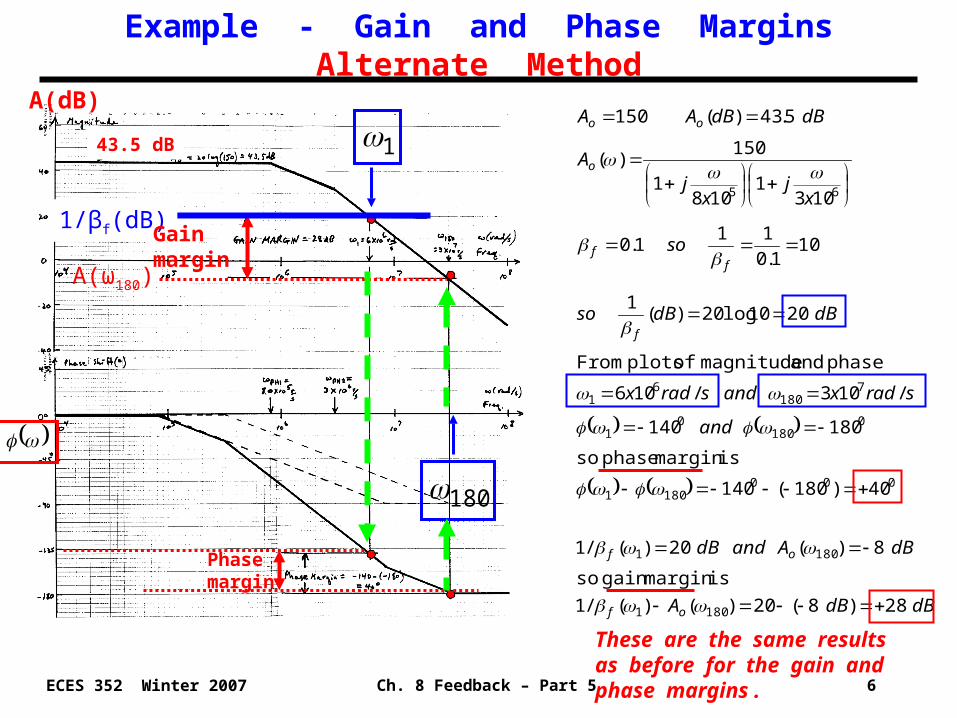
Example - Gain and Phase MarginsAlternate Method
dBdBA
dBAanddB
and
sradxandsradx
dBdBso
so
xj
xj
A
dBdBAA
of
of
f
ff
o
oo
28)8(20)()(/1
ismargin gain so
8)(20)(/1
40)180(140
ismargin phase so
180140
/103/106
phase and magnitude of plots From
2010log20)(1
101.0
111.0
1031
1081
150)(
5.43)(150
1801
1801
0001801
0180
01
7180
61
65
Phase margin
1
180
1/βf(dB)
A(dB)
These are the same results as before for the gain andphase margins .
43.5 dB
A(ω180)
Gain margin
Ch. 8 Feedback – Part 5 7ECES 352 Winter 2007
Feedback Amplifier with Multiple Poles
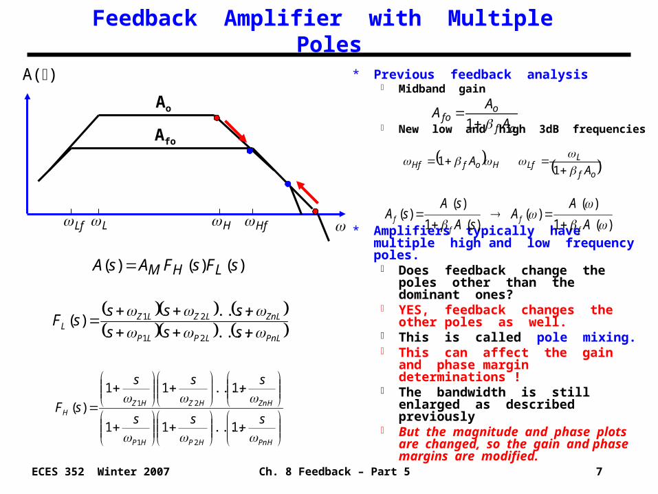
* Previous feedback analysis Midband gain
New low and high 3dB frequencies
* Amplifiers typically have multiple high and low frequency poles.
Does feedback change the poles other than the dominant ones?
YES, feedback changes the other poles as well.
This is called pole mixing. This can affect the gain and phase
margin determinations ! The bandwidth is still enlarged as
described previously But the magnitude and phase plots
are changed, so the gain and phase margins are modified.
PnLLPLP
ZnLLZLZL sss
ssssF
....
....)(
21
21
)(1
)()(
)(1
)()(
A
AA
sA
sAsA
ff
ff
of
ofo A
AA
1
of
LLfHofHf A
A
11
A()
Ao
H HfLf L
Afo
)()()( sFsFAsA LHM
PnHHPHP
ZnHHZHZH
sss
sss
sF
1....11
1....11
)(
21
21
Ch. 8 Feedback – Part 5 8ECES 352 Winter 2007
0
0
2
2
021
2
210
0
0
21
2
210
0
021
0
21
0
21
0
f
f
11
1
11
11
1
111
1111
1
11
1)(A
get weA(s)for ngSubstituti1
)(A
A
AAwhere
s
Q
s
A
A
s
A
s
A
A
ssA
A
Ass
A
ss
A
ss
A
sA
sAs
sA
sAs
ffo
oo
fo
fPHPHPHPHf
f
PHPHPHPHf
fPHPH
PHPH
f
PHPH
f
f
Feedback Effect on Amplifier with Two Poles
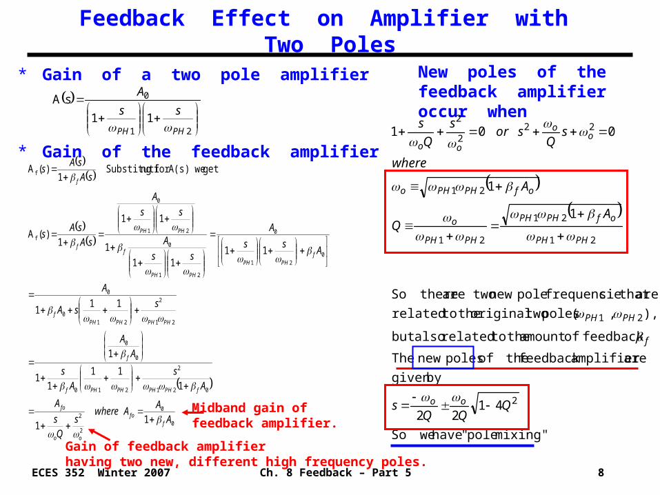
* Gain of a two pole amplifier
* Gain of the feedback amplifier
21
0
11
sA
PHPH
ss
A
New poles of the feedback amplifier occur when
mixing" pole" have weSo
4122
bygiven
are amplifier feedback theof poles new The
feedback ofamount the torelated alsobut
),,( poles twooriginal the torelated
are that sfrequencie pole new twoare thereSo
1
1
001
2
21
21
21
21
21
222
2
QQQ
s
AQ
A
where
sQ
sors
Q
s
oo
f
PHPH
PHPH
ofPHPH
PHPH
o
ofPHPHo
oo
oo
Midband gain of feedback amplifier.
Gain of feedback amplifierhaving two new, different high frequency poles.
Ch. 8 Feedback – Part 5 9ECES 352 Winter 2007
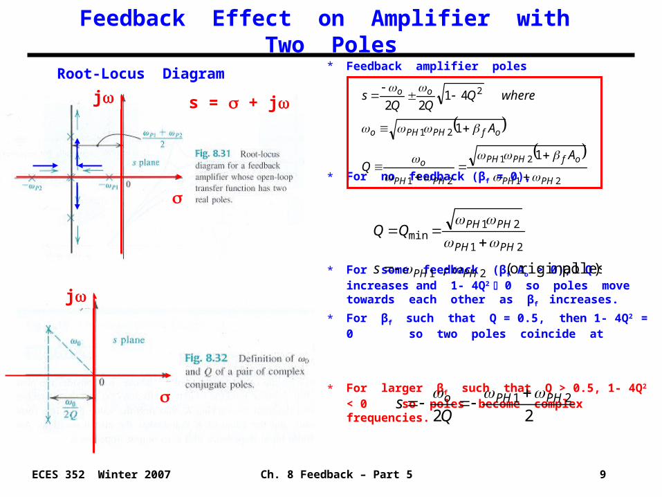
* Feedback amplifier poles
* For no feedback (βf = 0),
* For some feedback (βf Ao > 0), Q increases and 1- 4Q2 0 so poles move towards each other as βf increases.
* For βf such that Q = 0.5, then 1- 4Q2 = 0 so two poles coincide at
* For larger βf such that Q > 0.5, 1- 4Q2 < 0 so poles become complex frequencies.
Feedback Effect on Amplifier with Two Poles
21
21
21
21
2
1
1
4122
PHPH
ofPHPH
PHPH
o
ofPHPHo
oo
AQ
A
whereQQQ
s
)poles original(, 21
21
21min
PHPH
PHPH
PHPH
s
2221 PHPHo
Qs
Root-Locus Diagram
s = + jj
j
Ch. 8 Feedback – Part 5 10ECES 352 Winter 2007
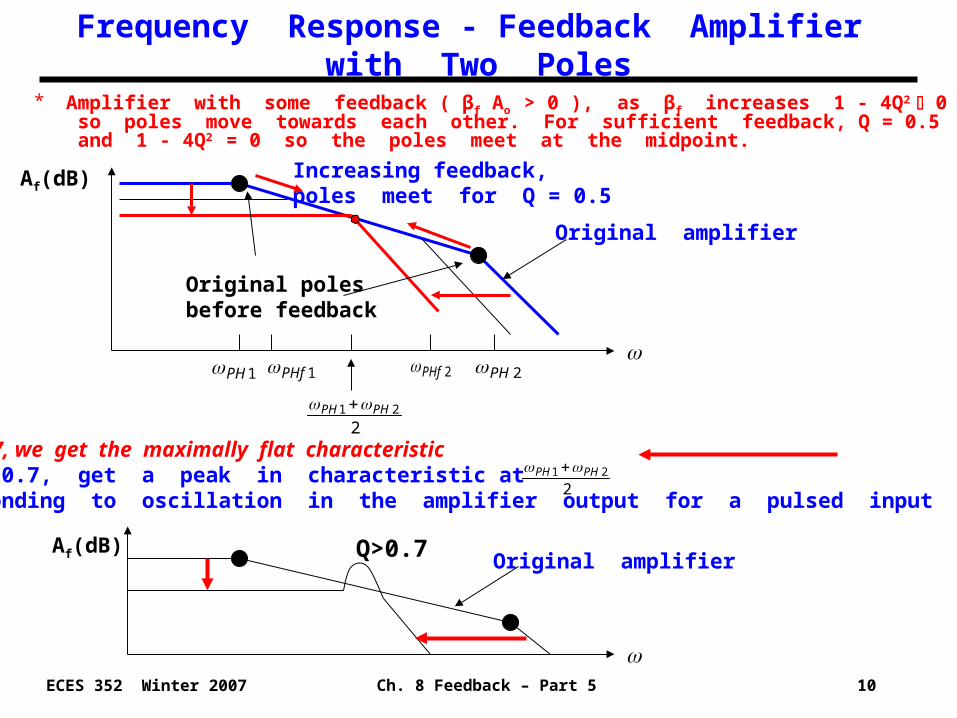
* Amplifier with some feedback ( βf Ao > 0 ), as βf increases 1 - 4Q2 0 so poles move towards each other. For sufficient feedback, Q = 0.5 and 1 - 4Q2 = 0 so the poles meet at the midpoint.
Frequency Response - Feedback Amplifier with Two Poles
Af(dB)
1PHf
2PH
Af(dB)
221 PHPH
2PHf1PH
Original amplifier
* For Q = 0.707, we get the maximally flat characteristic* For Q > 0.7, get a peak in characteristic at corresponding to oscillation in the amplifier output for a pulsed input (undesirable).
Original amplifier
Increasing feedback, poles meet for Q = 0.5
221 PHPH
Q>0.7
Original poles before feedback
Ch. 8 Feedback – Part 5 11ECES 352 Winter 2007
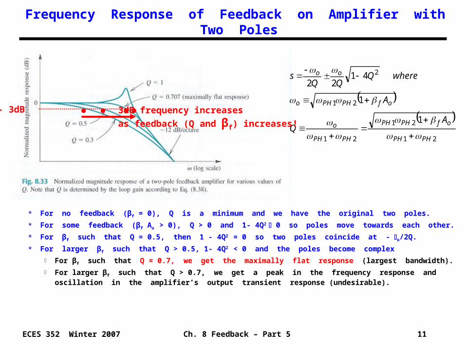
Frequency Response of Feedback on Amplifier with Two Poles
21
21
21
21
2
1
1
4122
PHPH
ofPHPH
PHPH
o
ofPHPHo
oo
AQ
A
whereQQQ
s
* For no feedback (βf = 0), Q is a minimum and we have the original two poles.
* For some feedback (βf Ao > 0), Q > 0 and 1- 4Q2 0 so poles move towards each other.
* For βf such that Q = 0.5, then 1 - 4Q2 = 0 so two poles coincide at - o/2Q.
* For larger βf such that Q > 0.5, 1- 4Q2 < 0 and the poles become complex
For βf such that Q = 0.7, we get the maximally flat response (largest bandwidth).
For larger βf such that Q > 0.7, we get a peak in the frequency response and oscillation in the amplifier’s output transient response (undesirable).
3dB frequency increases
as feedback (Q and βf) increases!
- 3dB
Ch. 8 Feedback – Part 5 12ECES 352 Winter 2007
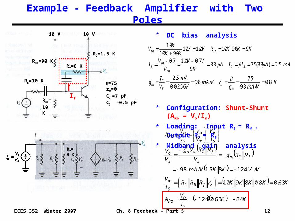
* DC bias analysis
* Configuration: Shunt-Shunt (ARo = Vo/Is)
* Loading: Input R1 = Rf , Output R2 = Rf
* Midband gain analysis
Example - Feedback Amplifier with Two Poles
Rs=10 K
RB1=90 K
RB2=10 K
RC=1.5 K
Rf=8 K
10 V 10 V
=75rx=0C =7 pFC =0.5 pF
KVmAg
rVmAV
mA
V
Ig
mAAIIAK
VV
R
VI
KKKRVVKK
KV
mT
Cm
BCTh
ThB
ThTh
8.0/98
75/98
0256.0
5.2
5.2)33(75339
7.00.17.0
990100.1109010
10
RB= 9 K
KK
I
VA
KKKKKrRRRI
V
VVKKVmA
RRgV
RRVg
V
V
I
V
V
V
I
VA
s
oRo
fBSS
fCmfCmo
s
o
s
oRo
8463.0124
63.08.08910
/12485.1/98
If
Ch. 8 Feedback – Part 5 13ECES 352 Winter 2007
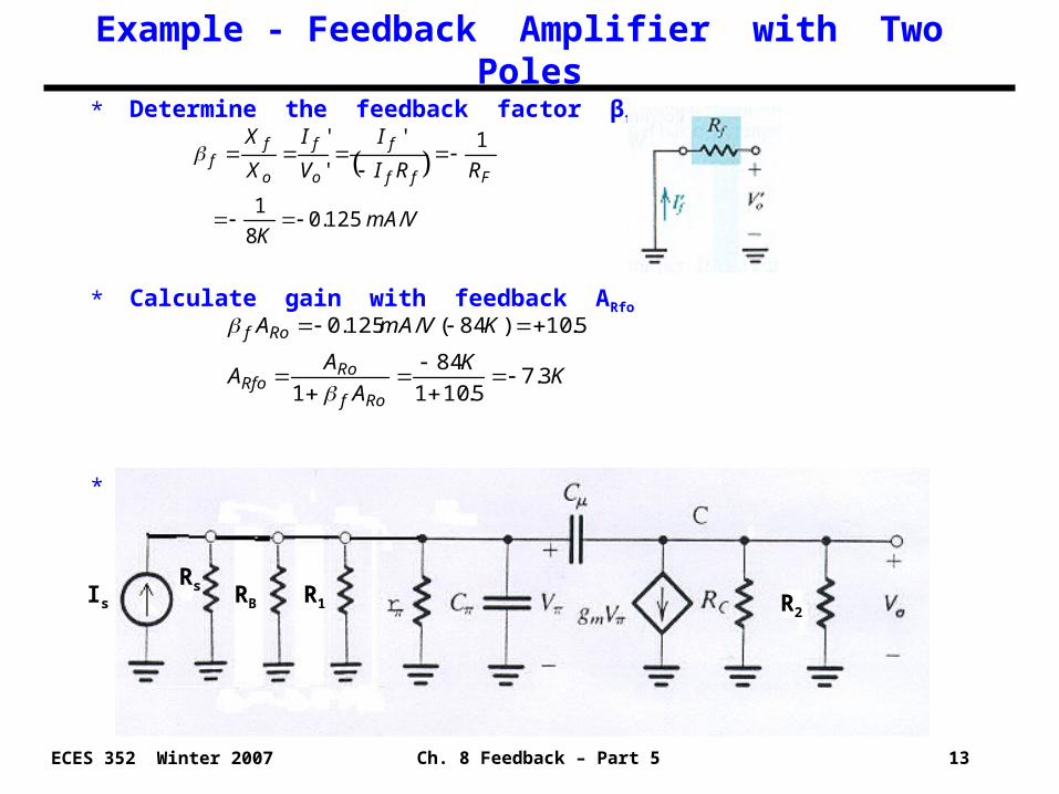
Example - Feedback Amplifier with Two Poles
* Determine the feedback factor βf
* Calculate gain with feedback ARfo
* High frequency ac equivalent circuit
VmA
K
RRI
I
V
I
X
X
Fff
f
o
f
o
ff
/125.08
1
1'
'
'
KK
A
AA
KVmAA
Rof
RoRfo
Rof
3.75.101
84
1
5.10)84(/125.0
Is
Rs RB R1 R2
Ch. 8 Feedback – Part 5 14ECES 352 Winter 2007
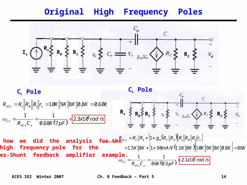
Original High Frequency Poles
Is
Rs RB R1 R2
C Pole
sradxpFKCR
KKKKKrRRRR
xCC
BsxC
/103.2768.0
11
68.08.08910
8
1
C Pole
Rs RB R1 R2
sradxpFKCR
KKKKKKKVmAKK
rRRRRRgRRR
xCC
BsCmCxC
/101.25.086
11
868.0891085.1/98185.1
1
7
122
See how we did the analysis for the C2 high frequency pole for the Series-Shunt feedback amplifier example.
Ch. 8 Feedback – Part 5 15ECES 352 Winter 2007
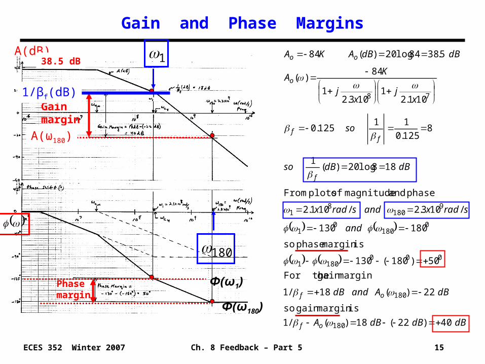
Gain and Phase Margins
dBdBdBA
dBAanddB
and
sradxandsradx
dBdBso
so
xj
xj
KA
dBdBAKA
of
of
f
ff
o
oo
40)22(18)(/1
ismargin gain so
22)(18/1
margingain For the
50)180(130
ismargin phase so
180130
/103.2/101.2
phase and magnitude of plots From
188log20)(1
8125.0
11125.0
101.21
103.21
84)(
5.3884log20)(84
180
180
0001801
0180
01
9180
81
78
Phase margin
Gain margin
1
180
1/βf(dB)
A(dB)
38.5 dB
A(ω180)
Φ(ω1)
Φ(ω180)
Ch. 8 Feedback – Part 5 16ECES 352 Winter 2007
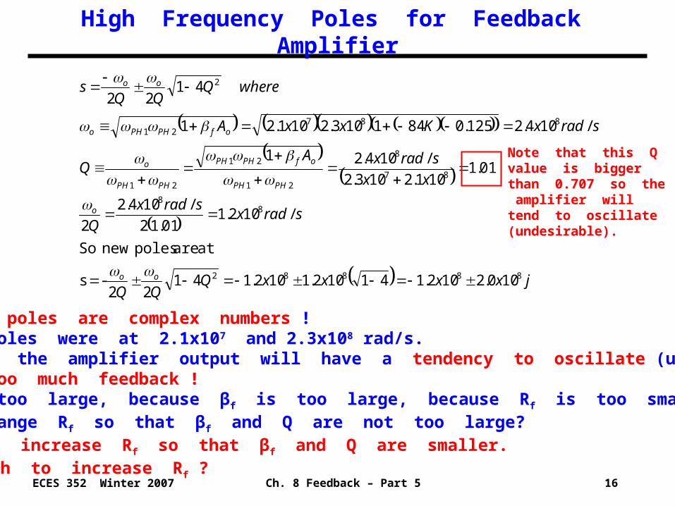
High Frequency Poles for Feedback Amplifier
jxxxxQQQ
sradxsradx
Q
xx
sradxAQ
sradxKxxA
whereQQQ
s
oo
o
PHPH
ofPHPH
PHPH
o
ofPHPHo
oo
88882
88
87
8
21
21
21
88721
2
100.2102.141102.1102.14122
-s
at are poles new So
/102.101.12
/104.2
2
01.1101.2103.2
/104.21
/104.2125.0841103.2101.21
4122
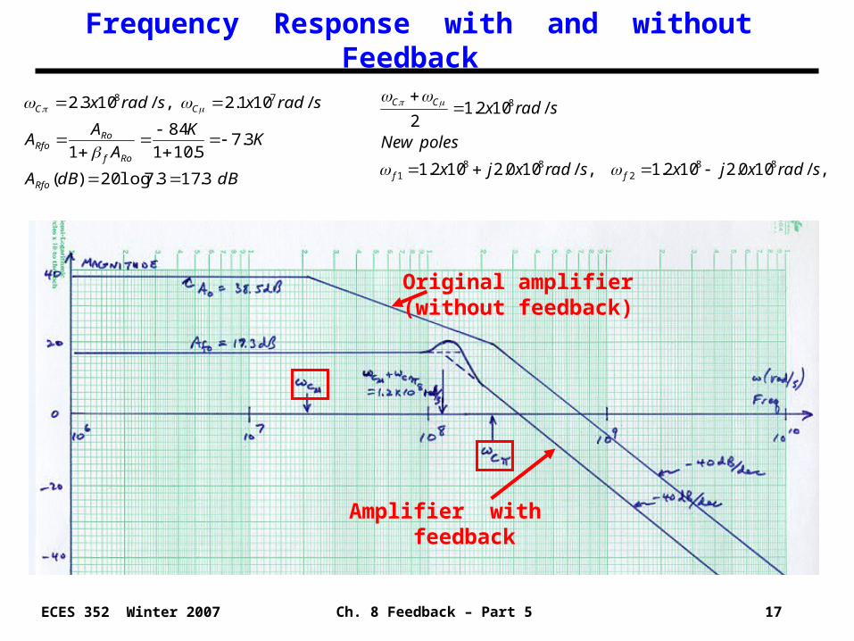
* These new poles are complex numbers !* Original poles were at 2.1x10⁷ and 2.3x10⁸ rad/s.* This means the amplifier output will have a tendency to oscillate (undesirable!)* We have too much feedback ! * Q is too large, because βf is too large, because Rf is too small (βf = - 1/Rf)!* How to change Rf so that βf and Q are not too large?
• Need to increase Rf so that βf and Q are smaller.• How much to increase Rf ?
Note that this Q value is bigger than 0.707 so the amplifier will tend to oscillate (undesirable).
Ch. 8 Feedback – Part 5 17ECES 352 Winter 2007
Frequency Response with and without Feedback
dBdBA
KK
A
AA
sradxsradx
Rfo
Rof
RoRfo
CC
3.173.7log20)(
3.75.101
84
1
/101.2 ,/103.2 78
Original amplifier(without feedback)
Amplifier with feedback
,/100.2102.1 ,/100.2102.1
/102.12
882
881
8
sradxjxsradxjx
polesNew
sradx
ff
CC
Ch. 8 Feedback – Part 5 18ECES 352 Winter 2007
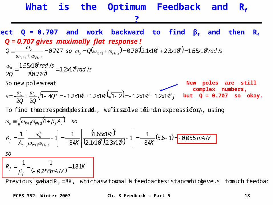
What is the Optimum Feedback and Rf ?
* Select Q = 0.707 and work backward to find βf and then Rf
* Q = 0.707 gives maximally flat response !
feedback.much toous gave which ,resistancefeedback a small tooas which w8K, R had we,Previously
1.18/055.0
11
/055.016.584
11
103.2101.2
1065.1
84
11
1
1
using for expressionan find tosolvefirst we,R desired ingcorrespond thefind To
102.1102.121102.1102.14122
-s
at are poles new So
/102.1707.02
/1065.1
2
/1065.1103.2101.2707.0707.0
f
87
28
21
2
21
f
88882
88
88721
21
KVmA
R
so
VmAKxx
x
KA
soA
jxxxxQQQ
sradxsradx
Q
sradxxxQsoQ
ff
PHPH
o
of
ofPHPHo
f
oo
o
PHPHoPHPH
o
New poles are still complex numbers, but Q = 0.707 so okay.

Ch. 8 Feedback – Part 5 19ECES 352 Winter 2007
Gain and Phase Margins for Optimal Bandwidth
dBdBdBA
dBAanddB
and
sradxandsradx
dBdBso
soNew
xj
xj
KA
dBdBAKA
of
of
f
ff
o
oo
2.48)23(2.25)(/1
ismargin gain so
23)(2.25/1
margingain For the
80)180(100
ismargin phase so
180100
/103.2/105.9
phase and magnitude of plots From
2.252.18log20)(1
2.18055.0
11055.0
101.21
103.21
84)(
5.3884log20)(84
180
180
0001801
0180
01
9180
71
78
Phase margin
Gain margin
1
180
1/βf(dB)
A(dB)
38.5 dB
A(ω180)
Ch. 8 Feedback – Part 5 20ECES 352 Winter 2007
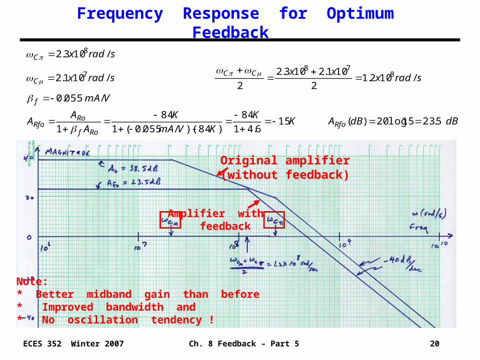
Frequency Response for Optimum Feedback
dBdBAKK
KVmA
K
A
AA
VmA
sradxxx
sradx
sradx
RfoRof
RoRfo
f
CCC
C
5.2315log20)( 156.41
84
)84)(/055.0(1
84
1
/055.0
/102.12
101.2103.2
2 /101.2
/103.2
878
7
8
Note: * Better midband gain than before * Improved bandwidth and * No oscillation tendency !
Original amplifier(without feedback)
Amplifier with feedback
Ch. 8 Feedback – Part 5 21ECES 352 Winter 2007
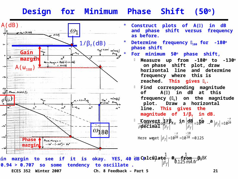
Design for Minimum Phase Shift (50o)
* Construct plots of A() in dB and phase shift versus frequency as before.
* Determine frequency 180 for -180o phase shift
* For minimum 50o phase shift, Measure up from -180o to -130o on
phase shift plot, draw horizontal line and determine frequency where this is reached. This gives 1.
Find corresponding magnitude of A() in dB at this frequency (1) on the magnitude plot. Draw a horizontal line. This gives the magnitude of 1/βf in dB.
Convert 1/βf in dB to a decimal
Calculate Rf from βf
125.01010get weHere
101011
log20)(1
20
18
20
2020
x
f
x
f
x
fff
xdB
KVmA
Rf
f 8/125.0
11
A(dB)
Phase margin
Gain margin
1
180
1/βf(dB)
*Check gain margin to see if it is okay. YES, 40 dB !*But Q = 0.94 > 0.707 so some tendency to oscillate .
A(ω180)
Ch. 8 Feedback – Part 5 22ECES 352 Winter 2007
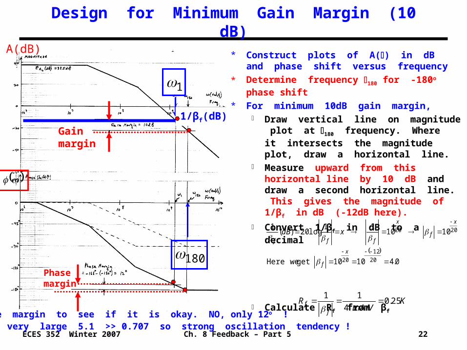
Design for Minimum Gain Margin (10 dB)
* Construct plots of A() in dB and phase shift versus frequency
* Determine frequency 180 for -180o phase shift
* For minimum 10dB gain margin, Draw vertical line on magnitude plot at
180 frequency. Where it intersects the magnitude plot, draw a horizontal line.
Measure upward from this horizontal line by 10 dB and draw a second horizontal line. This gives the magnitude of 1/βf in dB (-12dB here).
Convert 1/βf in dB to a decimal
Calculate Rf from βf
0.41010get weHere
101011
log20)(1
20
12
20
2020
x
f
x
f
x
fff
xdB
KVmA
Rf
f 25.0/4
11
Phase margin
Gain margin
1
180
1/βf(dB)
A(dB)
*Check phase margin to see if it is okay. NO, only 12o !*Q is also very large 5.1 >> 0.707 so strong oscillation tendency !
Ch. 8 Feedback – Part 5 23ECES 352 Winter 2007
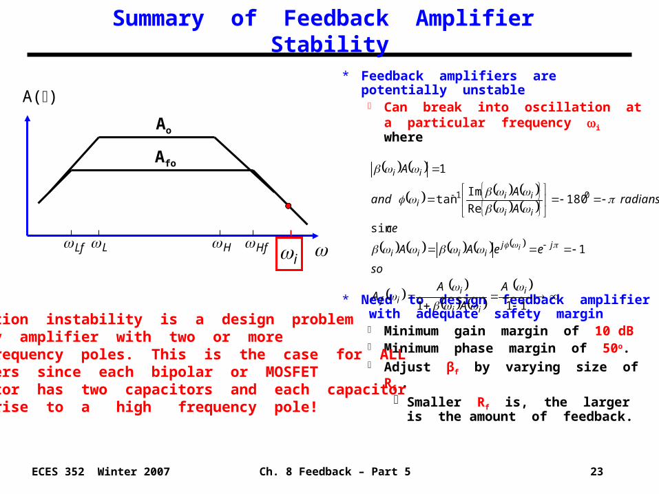
Summary of Feedback Amplifier Stability
* Feedback amplifiers are potentially unstable
Can break into oscillation at a particular frequency i where
* Need to design feedback amplifier with adequate safety margin
Minimum gain margin of 10 dB Minimum phase margin of 50o. Adjust βf by varying size of Rf .
Smaller Rf is, the larger is the amount of feedback.
111
1
sin
180Re
Imtan
1
01
i
ii
iif
jjiiii
ii
iii
ii
A
A
AA
so
eeAA
ce
radiansA
Aand
A
i
A()
Ao
H HfLf L
Afo
i
Oscillation instability is a design problem for any amplifier with two or more high frequency poles. This is the case for ALL amplifiers since each bipolar or MOSFET transistor has two capacitors and each capacitor gives rise to a high frequency pole!