federal aviation administration · eb no. 95 faa airport engineering division page 2 of 11 6.0....
TRANSCRIPT
Federal Aviation Administration
Memorandum DEC 1 9 2017Date:
To:
],.,-J~ From: Khalil E. Kod ·, P.~1anager, Airport Engineering Division, AAS-100
Subject: INFORMATION: Engineering Brief No. 95, Additional Siting and Survey considerations for Precision Approach Path Indictor (PAPI) and Other Visual Glide Slope Indicators (VGSI)
All Regional Airports Division Managers
.
This Engineering Brief(EB) 95 provides clarification and additional guidance to airports, Airport District Offices (AD0s), and architectural and engineering companies regarding updated PAPI and VGSI flight check inspection criteria defined in the Federal Aviation Administration (FAA) Order 8200. ID.
Attachment.

EB No. 95 FAA Airport Engineering Division Page 1 of 11
FAA Airport Safety and Standards
ENGINEERING BRIEF NO. 95
Additional Siting and Survey Considerations for Precision Approach Path
Indictor (PAPI) and Other Visual Glide Slope Indicators (VGSI)
1.0. Purpose.
This Engineering Brief (EB) provides clarification and guidance to airports, Airport
District Offices (ADOs), and architectural and engineering companies about updated
PAPI and VGSI flight check inspection criteria defined in the Federal Aviation
Administration (FAA) Order 8200.1D, United States Standard Flight Inspection Manual.
2.0. Background.
New Obstacle Clearance Surface (OCS) penetration evaluation criteria defined in the
updated FAA Order 8200.1D caused issues with airport PAPI commissioning after
several failed FAA Flight Inspections. These issues caused 14 CFR Part 139 and general
aviation (GA) airports to delay commissioning PAPI and other VGSI systems.
These field issues indicated that airports, ADOs, and architectural and engineering
companies require clarification of the new OCS penetration criteria evaluated during
flight inspections.
This Engineering Brief provides clarification and additional guidance to mitigate future
non-federal PAPI and other non-federal VGSI commissioning issues.
3.0. Application.
This EB must be used with the other applicable documents listed in Section 6.0.
4.0. Description.
This EB provides clarification and guidance to airport operators during the design phase
of a new non-federal PAPI installation, modification, and/or recommissioning of an
existing non-federal PAPI or non-federal VGSI installation.
5.0. Effective Date.
This EB will be effective once signed by the Manager, Airport Engineering Division,
AAS-100.

EB No. 95 FAA Airport Engineering Division Page 2 of 11
6.0. Applicable Documents.
FAA AC 150/5340-30, Design and Installation Details for Airport Visual Aids
FAA Order 8200.1D, United States Standard Flight Inspection Manual
7.0. Clarification of New PAPI/VGSI OCS Penetration Evaluation Criteria.
The PAPI OCS penetration evaluation criteria is defined in FAA Order 8200.1D as
follows:
a. Chapter 7, paragraph 3b(4)(c)(i) requires that FAA Flight Inspection will evaluate
OCS penetrations to 8 nautical miles from threshold for Type L-880 (4-box)
PAPI. This may be reduced to 4 nautical miles for a Type L-881 (2-box) PAPI.
b. Chapter 7, paragraph 3b(4)(c)(v) extends the evaluation of the obstacle clearance
within the lateral limits of the visible light beam, even if it means going outside
the standard 10-degree to 10-degree obstacle protection area centered on the
runway. It also states, if the obstacle outside the standard 10-degree azimuth
poses a risk to aircraft maneuvering to land, the azimuth spread of the light beam
shall be suitably restricted so that the object remains outside the confines of the
light beam.
7.1. Clarification of extension of OCS up to 8 nautical miles.
For commissioning-type inspections, obstacle penetrations within the obstacle evaluation
area defined in FAA Order 8200.1D must be identified and mitigated. However,
PAPI/VGSI operation does not require the airport operator to mitigate obstacles in the
approach area beyond 4 nautical miles from the runway threshold.
Note: Obstacle penetrations beyond 4 nautical miles will typically result in a restriction
to the usable distance of the PAPI/VGSI, per Chapter 7, paragraph 3b(4)(c)(iii) of FAA
Order 8200.1D.
7.2. Clarification of obstacle evaluation outside 10-degrees.
The data collected by the FAA from the installed and operational PAPIs indicate that the
horizontal light beam or light signal spread from a PAPI can be up to ±13 degrees from
the runway centerline. This is due to the PAPI being located off to the side of the runway
and design requirements for light distribution and intensity. FAA Flight Inspection now
evaluates the complete angular coverage of the PAPI light beam, beyond the 10-degree to
10-degree OCS. The obstacle-free requirement will necessitate the new Light Signal
Clearance Surface (LSCS) to be surveyed, as defined in Section 8.0, for the airport
operators. The new LSCS survey is in addition to the OCS siting survey. This survey
will ensure that obstacle penetrations are addressed during the design phase of the project
to identify and resolve issues early in the project before FAA Flight Inspection.
Note: The clarification of the new PAPI OCS penetration evaluation criteria has been
discussed with the FAA Flight Inspection Team (AJW-3330) and their concurrence is
documented in an internal memorandum dated June 22, 2017 (see Appendix A).

EB No. 95 FAA Airport Engineering Division Page 3 of 11
8.0. New Clearance Surface and Survey: PAPI Light Signal Clearance Surface (LSCS).
During the design phase or during the replacement of a PAPI/VGSI project, the OCS
siting survey must be performed from the centerline of the runway to evaluate obstacle
penetrations. However, PAPI light housing assemblies (LHAs) are not located at the
centerline of the runway. On a 150-foot wide runway, the innermost LHA and the
outermost LHA can be as far as 135 feet and 225 feet away from a runway centerline,
respectively. Therefore, the PAPI light signal can be seen outside the OCS.
For this reason, a PAPI LSCS has been defined that will assist the airport in identifying
obstacle penetrations outside the OCS. The new LSCS survey must be performed during
the design phase or replacement of a PAPI/VGSI project. This PAPI LSCS is based on
the clarification described in Section 7.2. Figure 1 shows an example of a PAPI OCS and
LSCS that require different surveys to identify obstacle penetrations and light signal
obstructions.

EB No. 95 FAA Airport Engineering Division Page 4 of 11
Figure 1. PAPI Obstacle Clearance Surface (OCS) and Light Signal Clearance Surface
(LSCS)
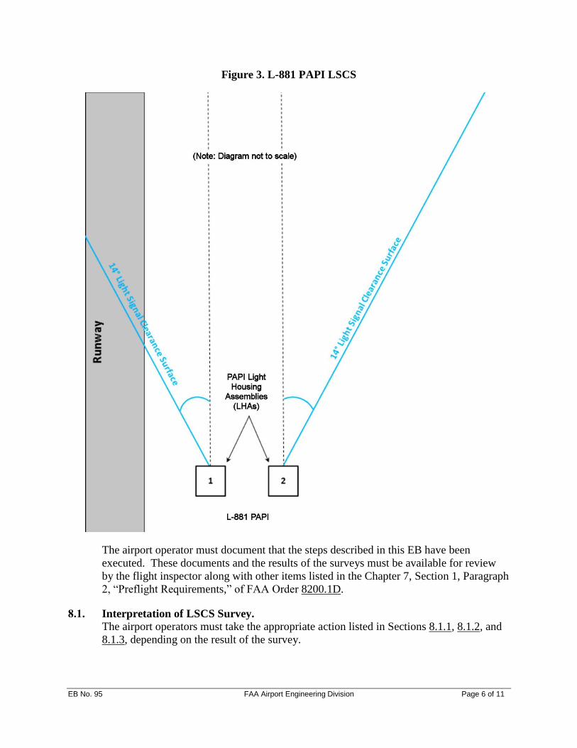
The LSCS originates at the LHAs and proceeds outward at an angle of 1 degree less than
the lowest course signal and extends 14 degrees to the left side of the first LHA (closest
to runway), the area between, and 14 degrees to the right side of the outermost LHA
(farthest from the runway). The lowest course signal for 4-box PAPI (L-880) is the
aiming angle of the third LHA and for 2-box PAPI (L-881) is the aiming angle of the unit
farthest from the runway. The LSCS extends from the point of origin, as shown in Figure
2 and Figure 3, and to a distance of 8 nautical miles from the runway threshold.
Note: The LSCS is the same if the PAPI is located on the right side of the runway.

EB No. 95 FAA Airport Engineering Division Page 5 of 11
Figure 2. L-880 PAPI LSCS
EB No. 95 FAA Airport Engineering Division Page 6 of 11
Figure 3. L-881 PAPI LSCS
The airport operator must document that the steps described in this EB have been
executed. These documents and the results of the surveys must be available for review
by the flight inspector along with other items listed in the Chapter 7, Section 1, Paragraph
2, “Preflight Requirements,” of FAA Order 8200.1D.
8.1. Interpretation of LSCS Survey.
The airport operators must take the appropriate action listed in Sections 8.1.1, 8.1.2, and
8.1.3, depending on the result of the survey.

EB No. 95 FAA Airport Engineering Division Page 7 of 11
8.1.1. No obstacle penetration(s) within the LSCS up to 8 nautical miles.
The survey results indicate that there are no obstacle penetrations within the LSCS up to
8 nautical miles. The airport operator does not need to perform any additional actions.
8.1.2. Obstacle penetration(s) found within the LSCS between 4 and 8 nautical miles.
This survey result found that obstacle penetrations are present within the LSCS between
4 and 8 nautical miles. Figure 4 shows common LSCS obstacles.
As per Section 7.1, the airport operator will not be responsible for mitigating the
obstacle(s) beyond 4 nautical miles. However, the airport operator should inform FAA
Flight Inspection about the obstacle penetration (see Section 8.2). The usable distance of
the PAPI beyond 4 nautical miles will be restricted, and the FAA will enter appropriate
remarks in the Chart Supplement or similar publication as per section 3b(4)(c)(iii) of
FAA Order 8200.1D.
Figure 4. Common LSCS Obstacles
8.1.3. Obstacle penetration(s) within the LSCS within 4 nautical miles or less.
The airport operator must consider the following options in order to mitigate the obstacle
penetration issue if the survey result indicates the presence of any obstacles inside the

EB No. 95 FAA Airport Engineering Division Page 8 of 11
LSCS. This also applies to any penetrating obstacles found within the standard OCS area.
Appropriate analysis must be performed to ensure that the selected option will mitigate
the LSCS obstacle penetration issue. The airport operator should also consider any
obstacle that is very close to becoming an obstacle penetration. It is acceptable to be
conservative about safety considerations and to satisfy FAA Flight Inspection criteria.
1. Remove the obstacle(s) (e.g., remove trees or top trees).
2. Raise the glide path angle of the PAPI to provide minimum clearance above the
obstacle. (Check threshold crossing height requirements in AC 150/5340-30.)
3. Relocate the PAPI to a different siting location:
a. Upwind or downwind of the runway
b. Relocate to the other side of runway
4. Install baffles (sometimes called blanking devices). Baffles restrict/limit the light
signal angular coverage of the PAPI or other VGSI.
a. Please refer to Appendix B to select the appropriate baffle angle/baffle
alignment angle with obstacle penetrations within the LSCS. (For example, if
an obstacle penetration is identified at 10 degrees (identified obstacle angle),
then baffles should be installed and aligned to a baffle angle of 6 degrees.)
Baffles will ensure that VGSI path guidance is not visible in the vicinity of a
penetrating obstacle.
b. If multiple obstacle penetrations are found within the LSCS, choose the obstacle
penetration closest to the runway centerline as the identified obstacle angle.
c. Some situations may require a double set of baffles if obstacle penetrations are
found on both sides of the runway centerline.
d. Baffles will not work in every situation. The installation of baffles is very
conditional on site and scenario.
e. There are limitations to installing baffles on PAPI and other VGSI systems. If
the obstacle penetration (identified obstacle angle) is found to be less than 7
degrees during the LSCS, baffles may not work.
f. Normally, any baffling should not eliminate VGSI coverage on the runway
centerline extended.
5. In the case where the obstacle cannot be mitigated and baffling is not possible,
consider other options to restrict the usable distance of the PAPI/VGSI inside 4
nautical miles. The shortest distance that can be restricted is 1.3 nautical miles
allowing for a half-mile buffer for the penetration. As such, the closest obstacle
penetration allowed is 1.8 nautical miles from the runway threshold.
Note: The use of baffles to mitigate the obstacle penetration should be the last option to
considered. Reason: Baffles restrict the light signal from each individual lamp inside the
LHA from being visible beyond a prescribed point. Moreover, when baffles are installed,
the overall effect reduces the usable light signal angular coverage of the PAPI or other

EB No. 95 FAA Airport Engineering Division Page 9 of 11
VGSI system. Some PAPI system manufacturers provide PAPI baffle kits for their L-
880/L-881 LHAs. Field installation and alignment are the responsibility of the airport.
8.2. Flight Inspection.
When scheduling an FAA Flight Inspection, provide the following basic information to
the flight inspection dispatcher so the flight inspection pilot is aware of obstacle
penetrations and whether baffles are installed on the PAPI or other VGSI.
1. Obstacle penetrations
a. Left or right side of the approach to the runway (pilot’s point-of-view)
b. The obstacle penetration’s distance from the runway threshold (in nautical
miles)
c. Obstacle penetration information (e.g., type of obstacle, elevation, etc.)
d. Angle of the obstacle penetration from the runway centerline
2. Baffles
a. Baffles used or not
b. Angle of the baffles (expected reduction in coverage). For example, Runway 18,
left side of the approach, 3 nautical miles, terrain obstruction penetrates at 8
degrees and 2450 ft mean sea level (MSL). Baffles installed to remove coverage
beyond 4 degrees left of centerline.

EB No. 95 FAA Airport Engineering Division Page 10 of 11
Appendix A. Memorandum from Flight Inspection Team Clarifying new PAPI/VGSI OCS Requirements and new Siting Survey Procedure for Non-Federal PAPI/VGSI

EB No. 95 FAA Airport Engineering Division Page 11 of 11
Appendix B. PAPI Baffle Angle/Baffle Alignment Angle Selection
Surveyed Obstacle Penetration(s) within LSCS between LHA and 4 nautical miles*
Identified Obstacle
Angle from LHA
(Degrees)
Baffle Angle or Baffle
Alignment Angle
(Degrees)
7 3
7.5 3.5
8 4
8.5 4.5
9 5
9.5 5.5
10 6
10.5 6.5
11 7
11.5 7.5
12 8
12.5 8.5
13 9
13.5 9.5
14 10
*An identified obstacle angle LESS THAN 7 DEGREES with
baffles installed in LHAs may not satisfy FAA Flight
Inspection Criteria.
Example of Obstacle Penetrations: Trees, towers, building, and terrain can block PAPI
Light Signal or become a collision hazard to a landing aircraft.