fedél mintafeladat – femap v11 tube cap finite elements ... · fedél mintafeladat – femap v11...
TRANSCRIPT

Fedél mintafeladat – Femap v11 Tube Cap Finite Elements Analysis
Femap v11 Example
By János DEVECZ
(2017)
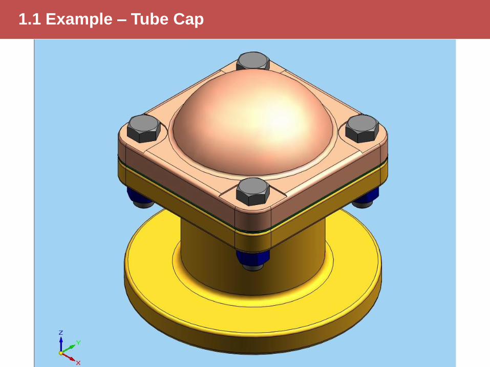
1.1 Example – Tube Cap
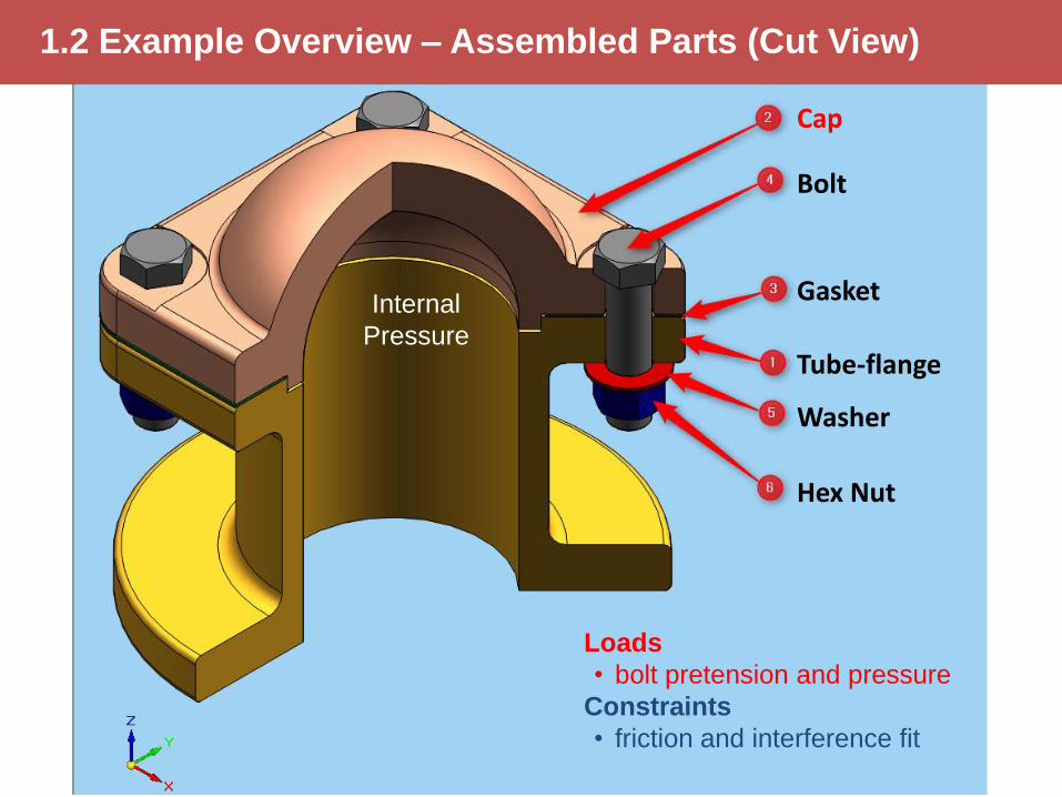
1.2 Example Overview – Assembled Parts (Cut View)
Cap
Bolt
Washer
Hex Nut
Gasket
Tube-flange
Internal
Pressure
Loads
• bolt pretension and pressure
Constraints
• friction and interference fit
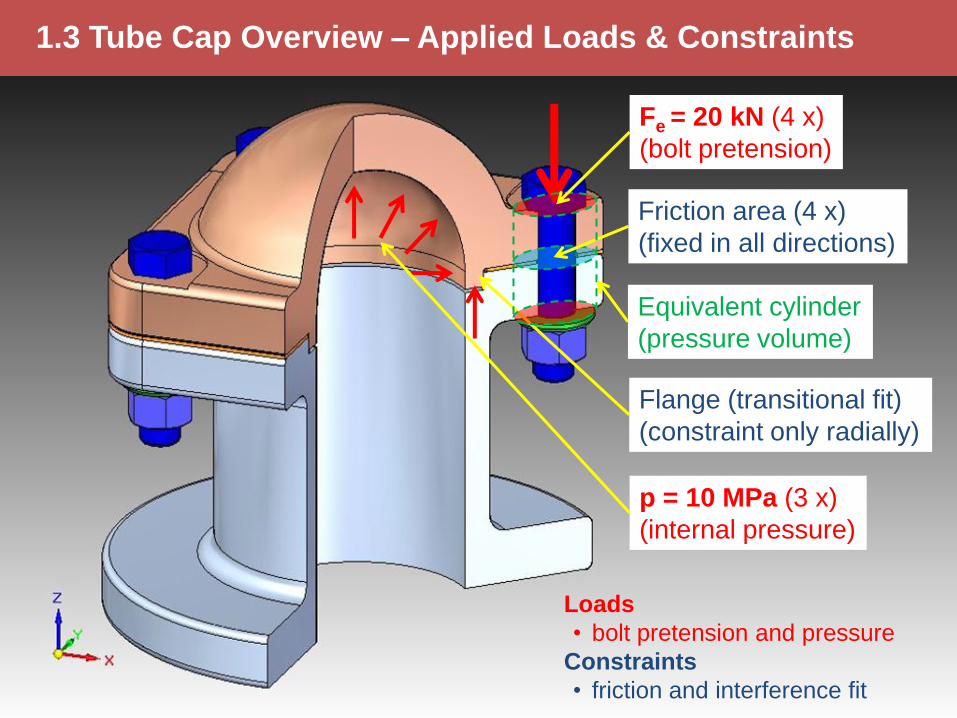
1.3 Tube Cap Overview – Applied Loads & Constraints
p = 10 MPa (3 x)
(internal pressure)
Fe = 20 kN (4 x)
(bolt pretension)
Friction area (4 x)
(fixed in all directions)
Flange (transitional fit)
(constraint only radially)
Equivalent cylinder
(pressure volume)
Loads
• bolt pretension and pressure
Constraints
• friction and interference fit
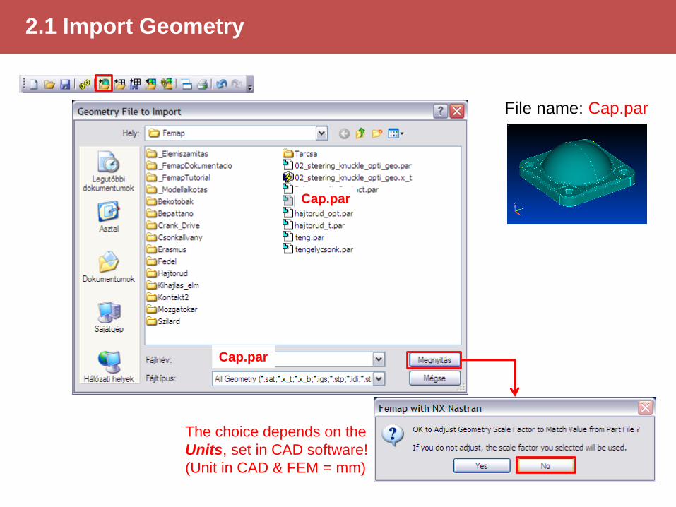
2.1 Import Geometry
The choice depends on the
Units, set in CAD software!
(Unit in CAD & FEM = mm)
Cap.par
Cap.par
File name: Cap.par
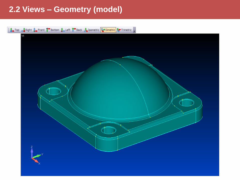
2.2 Views – Geometry (model)
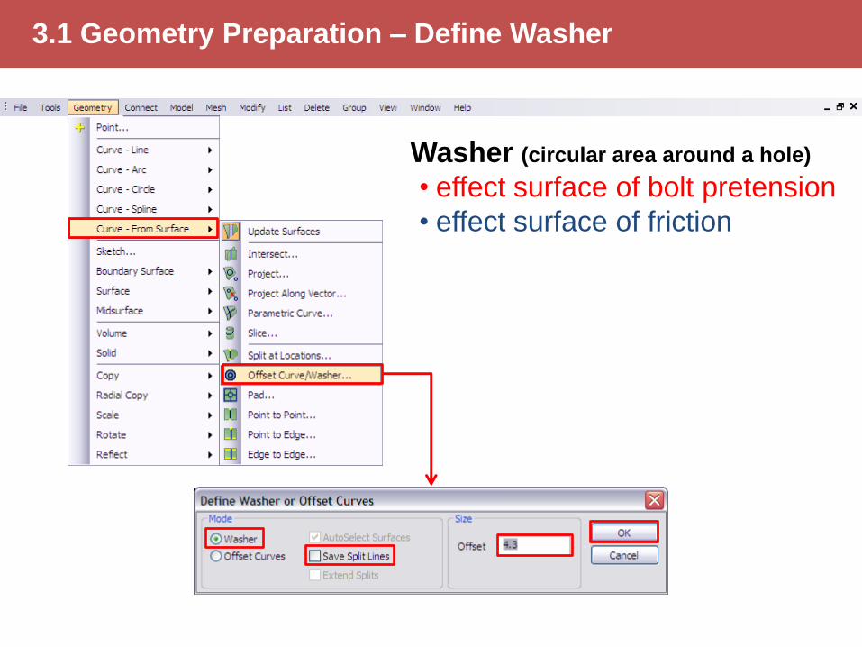
3.1 Geometry Preparation – Define Washer
Washer (circular area around a hole)
• effect surface of bolt pretension
• effect surface of friction
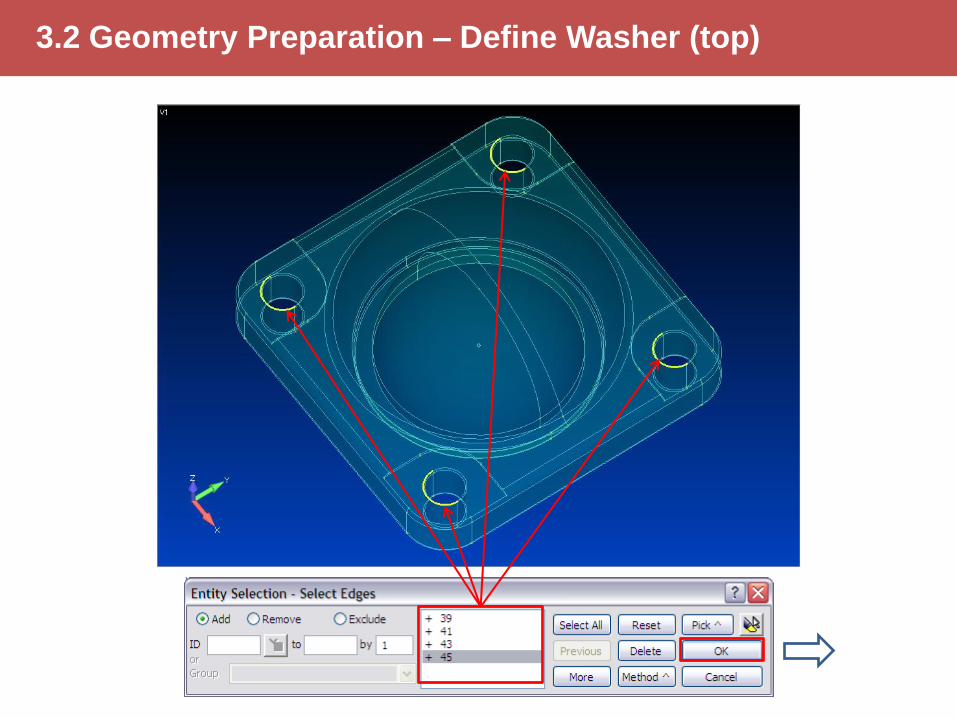
3.2 Geometry Preparation – Define Washer (top)
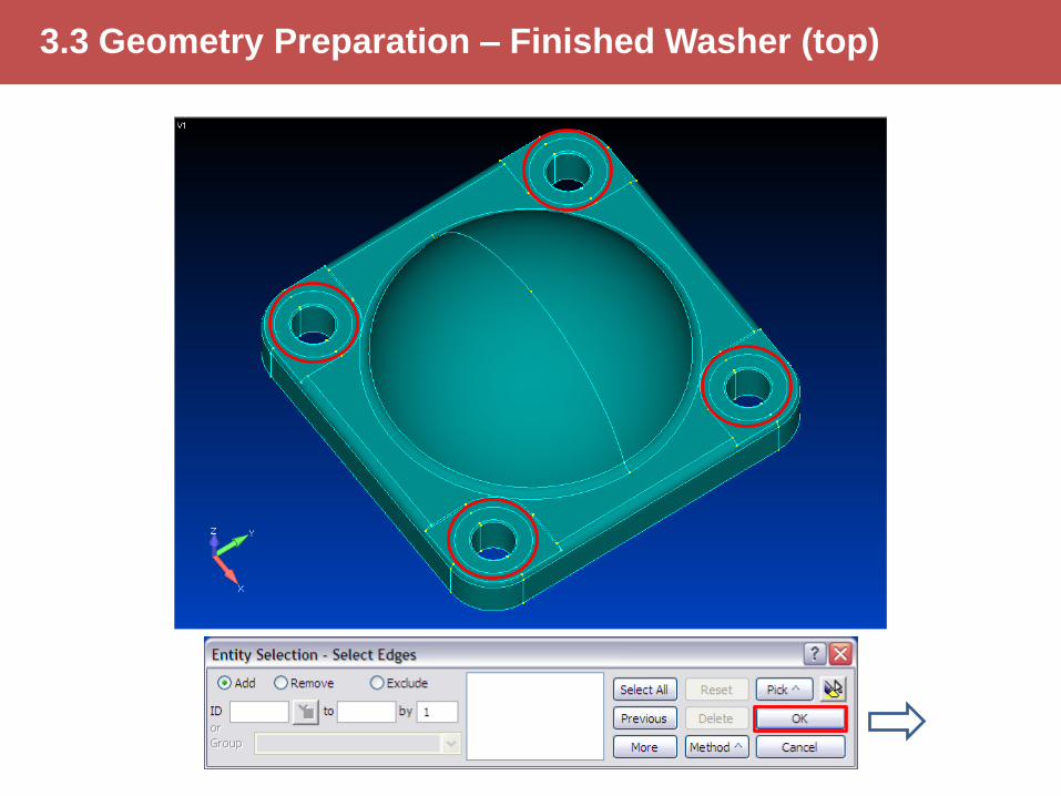
3.3 Geometry Preparation – Finished Washer (top)
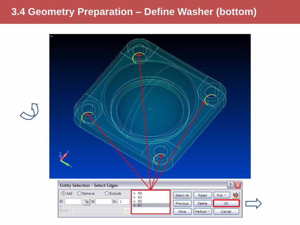
3.4 Geometry Preparation – Define Washer (bottom)

3.5 Geometry Preparation – Finished Washer (bottom)

3.6 Geometry Preparation – Exit Washer Command
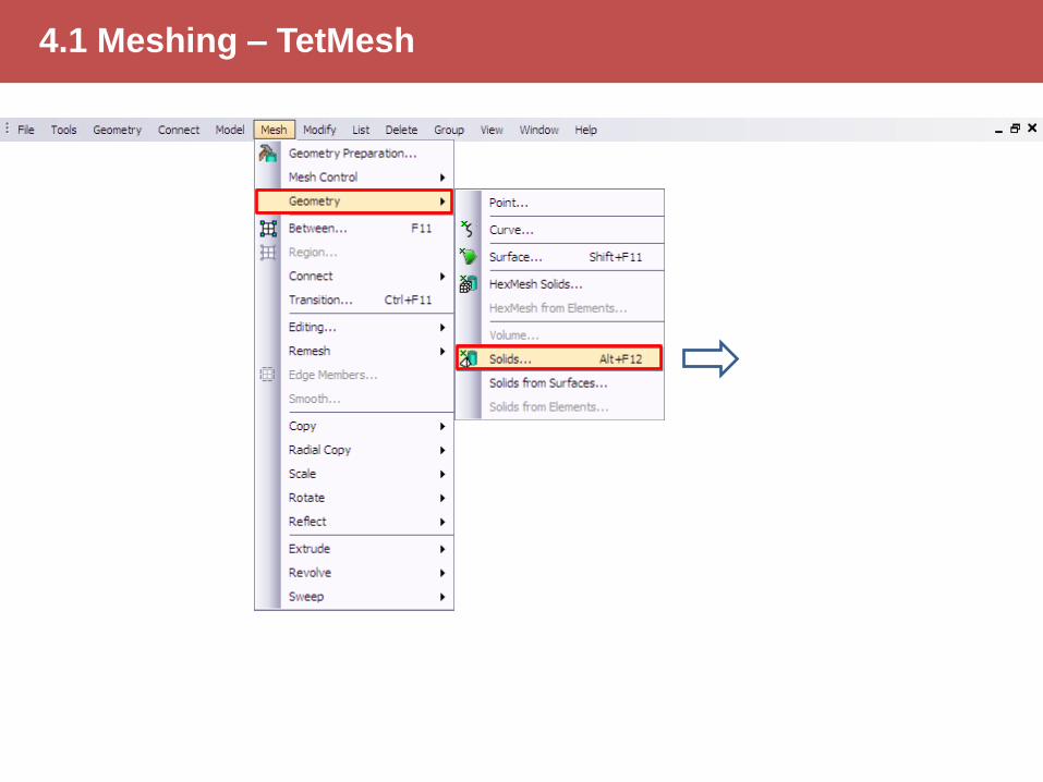
4.1 Meshing – TetMesh

4.2 Meshing – Open Material Database
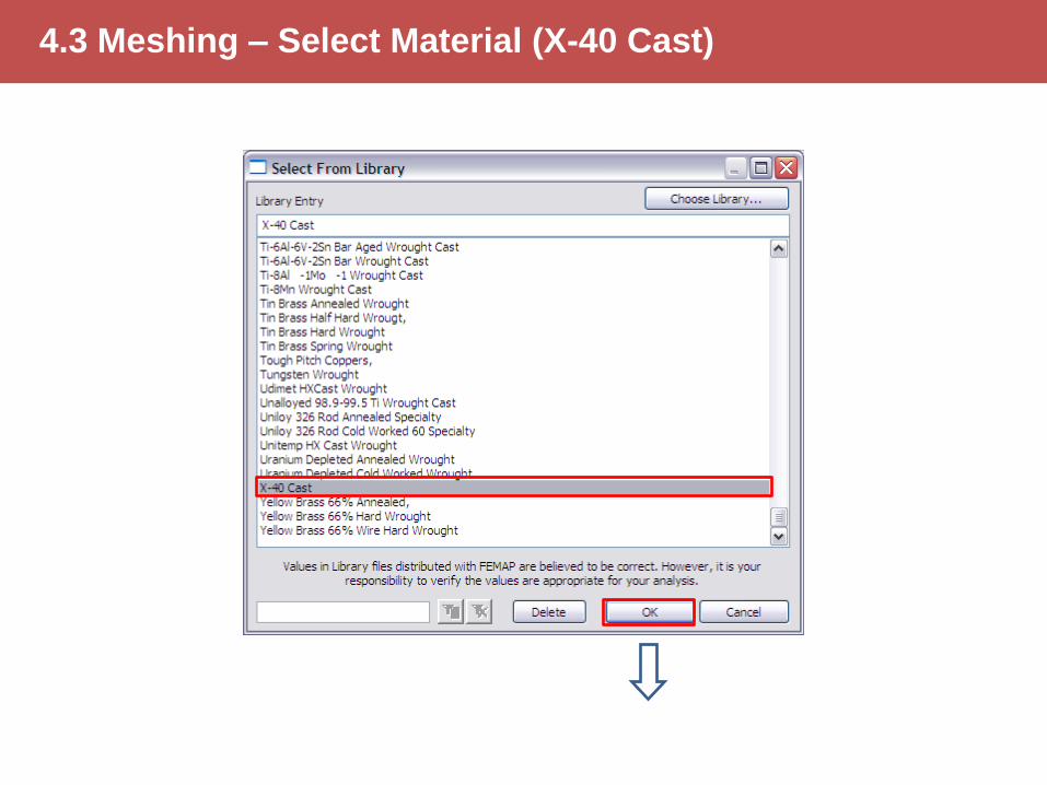
4.3 Meshing – Select Material (X-40 Cast)
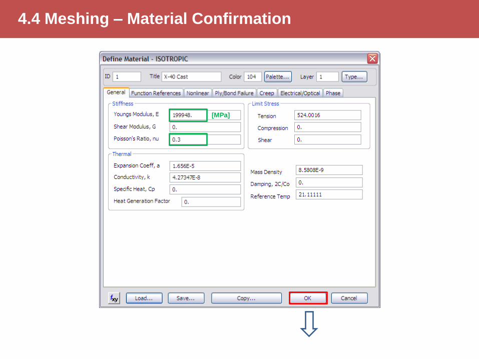
4.4 Meshing – Material Confirmation
[MPa]
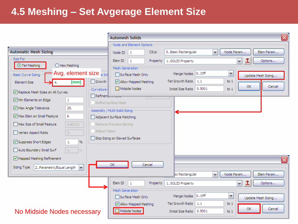
4.5 Meshing – Set Avgerage Element Size
Avg. element size
No Midside Nodes necessary
[mm]
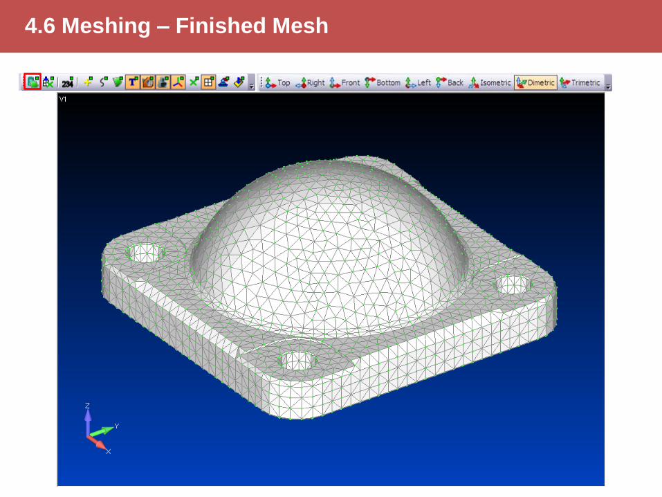
4.6 Meshing – Finished Mesh
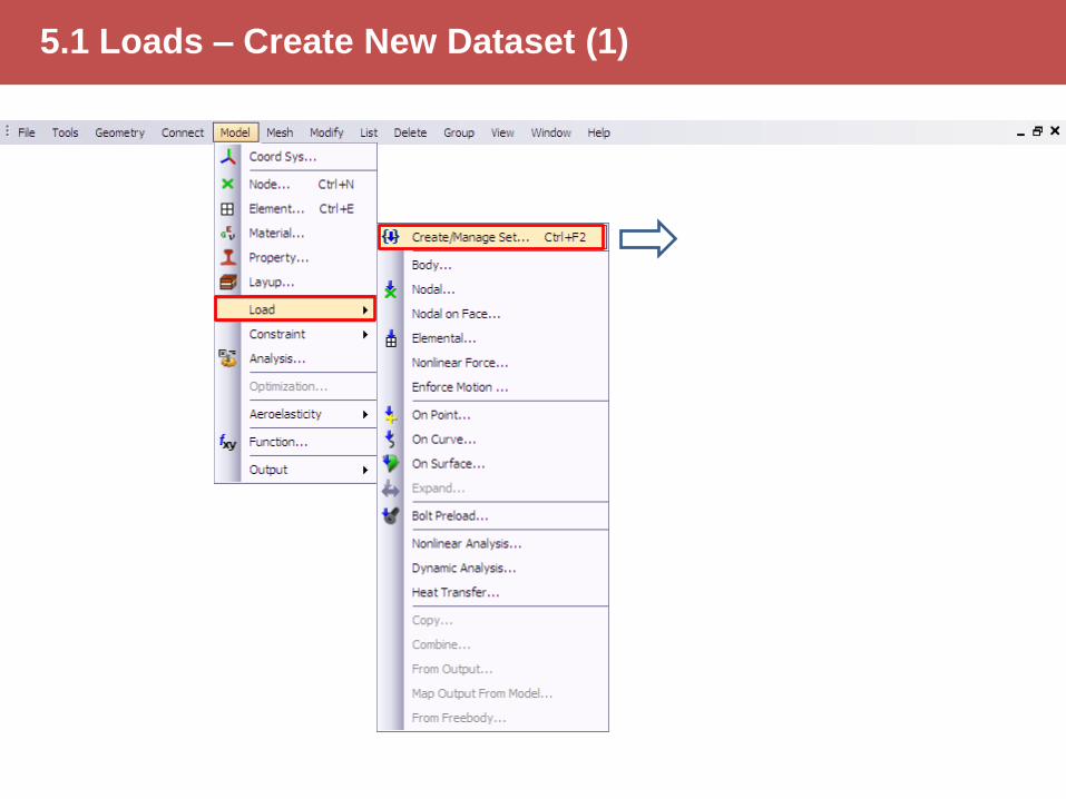
5.1 Loads – Create New Dataset (1)
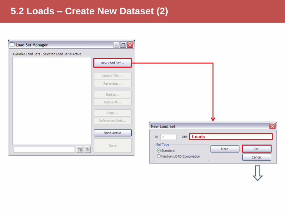
5.2 Loads – Create New Dataset (2)
Loads
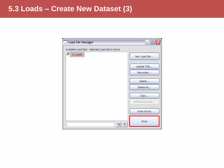
5.3 Loads – Create New Dataset (3)
1..Loads
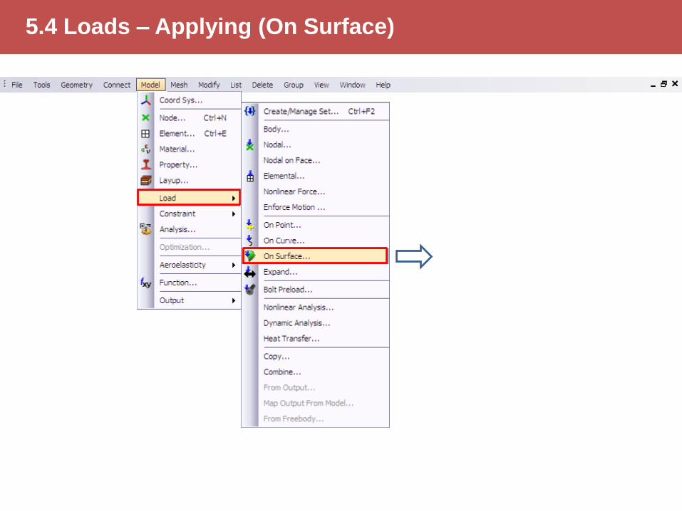
5.4 Loads – Applying (On Surface)
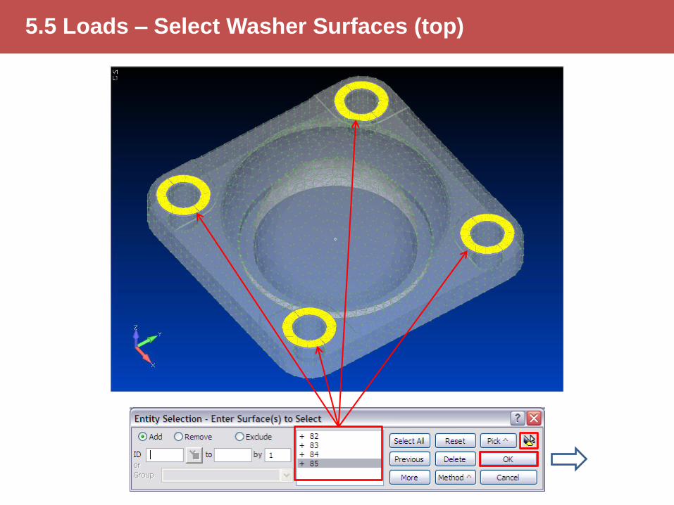
5.5 Loads – Select Washer Surfaces (top)
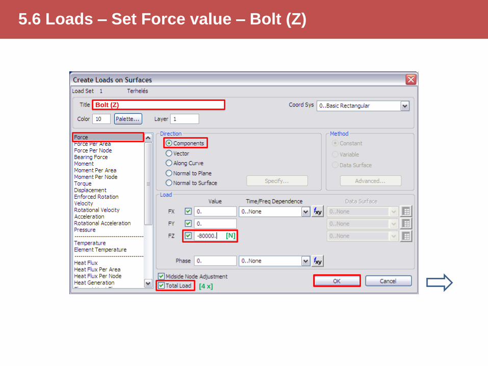
5.6 Loads – Set Force value – Bolt (Z)
Bolt (Z)
[N]
[4 x]
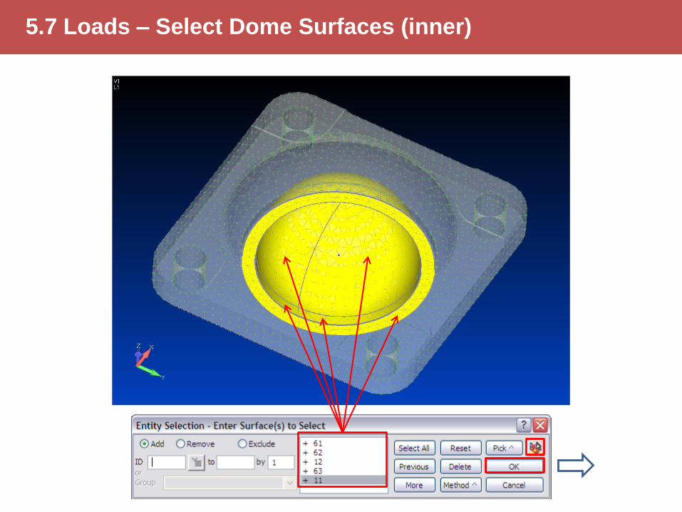
5.7 Loads – Select Dome Surfaces (inner)
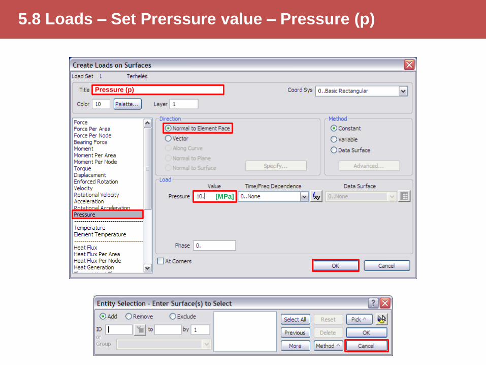
5.8 Loads – Set Prerssure value – Pressure (p)
Pressure (p)
[MPa]
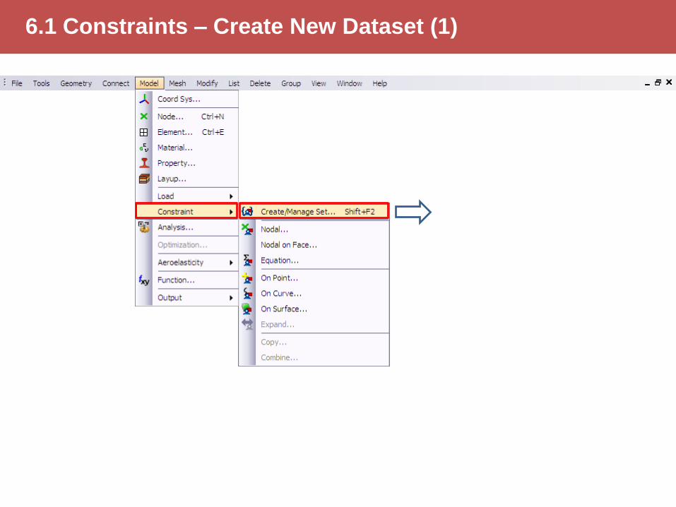
6.1 Constraints – Create New Dataset (1)
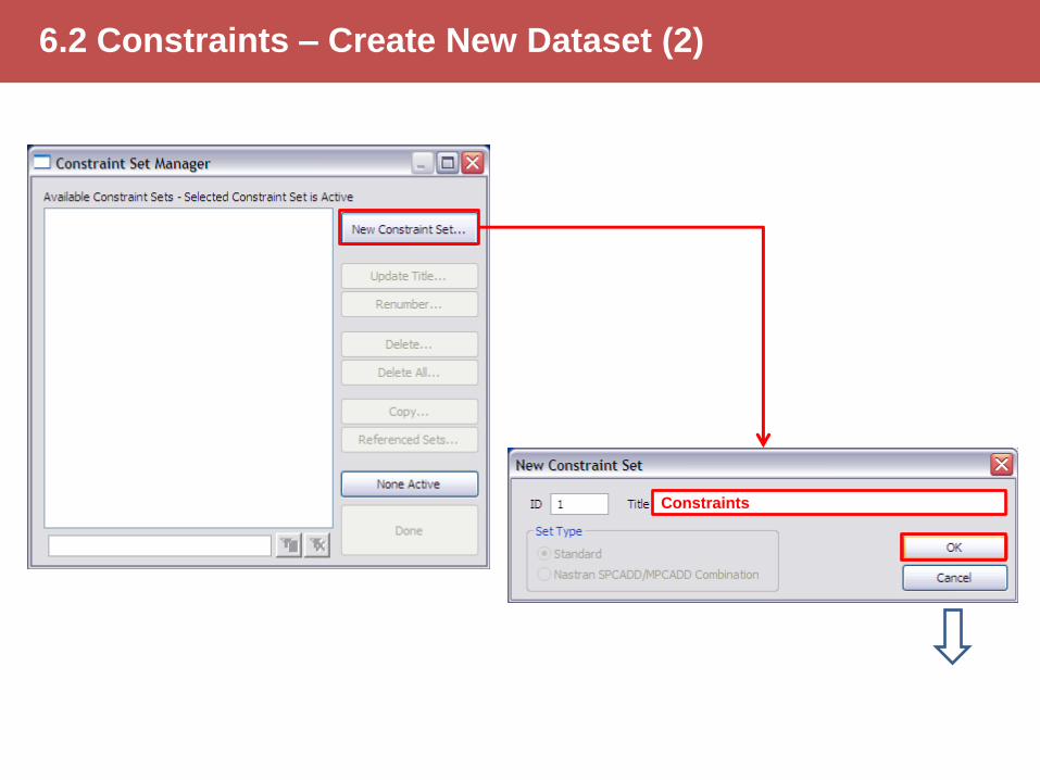
6.2 Constraints – Create New Dataset (2)
Constraints
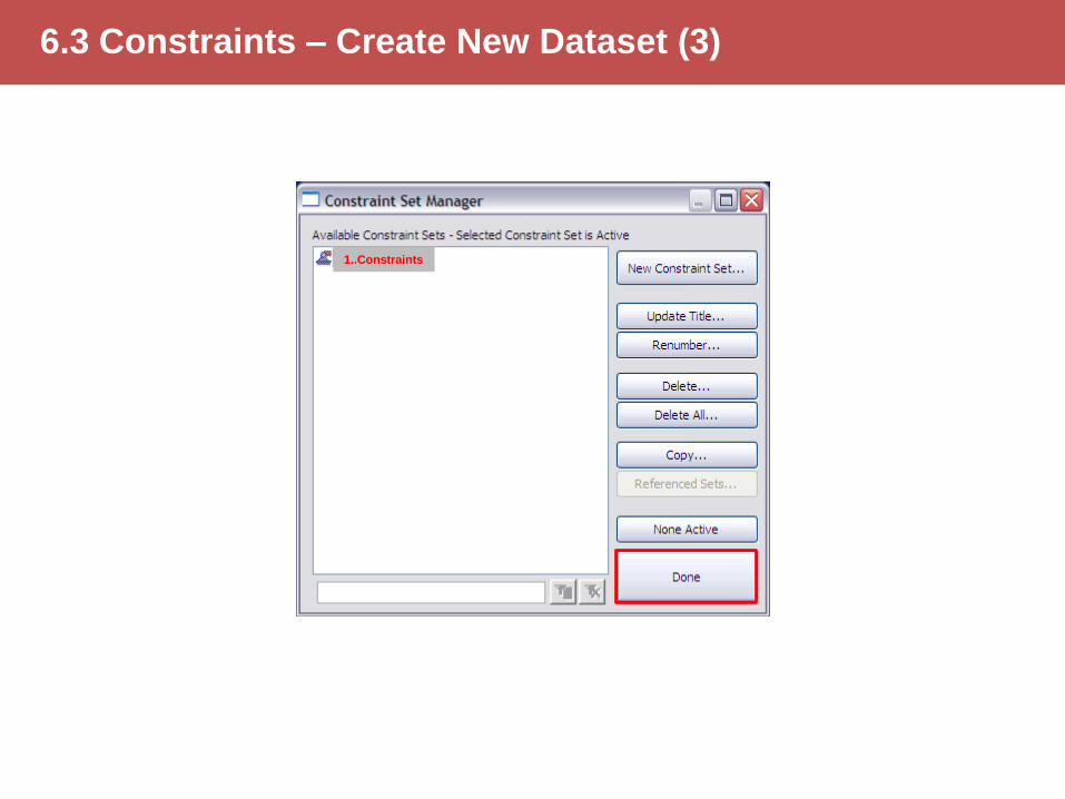
6.3 Constraints – Create New Dataset (3)
1..Constraints
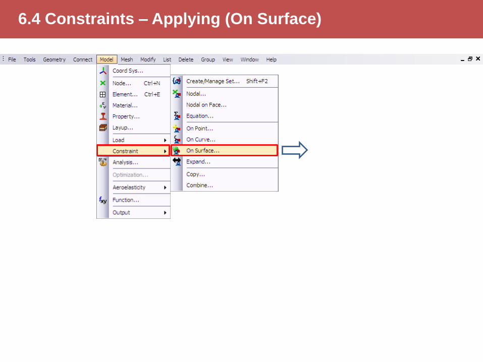
6.4 Constraints – Applying (On Surface)

6.5 Constraints – Select Washer Surfaces (bottom)
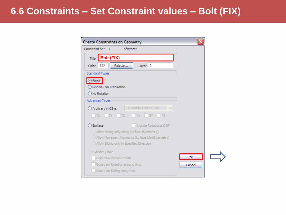
6.6 Constraints – Set Constraint values – Bolt (FIX)
Bolt (FIX)
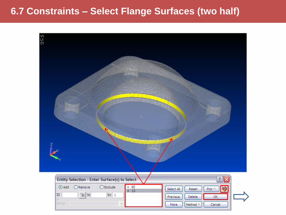
6.7 Constraints – Select Flange Surfaces (two half)
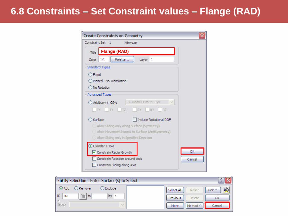
6.8 Constraints – Set Constraint values – Flange (RAD)
Flange (RAD)
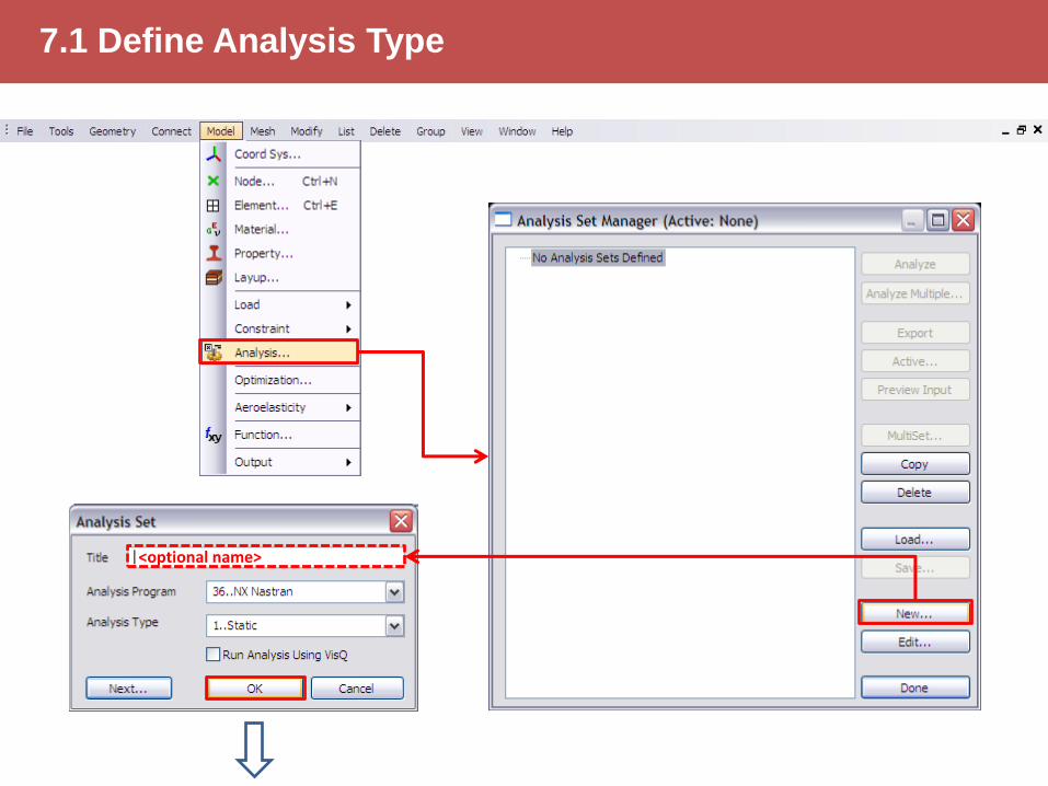
7.1 Define Analysis Type
<optional name>
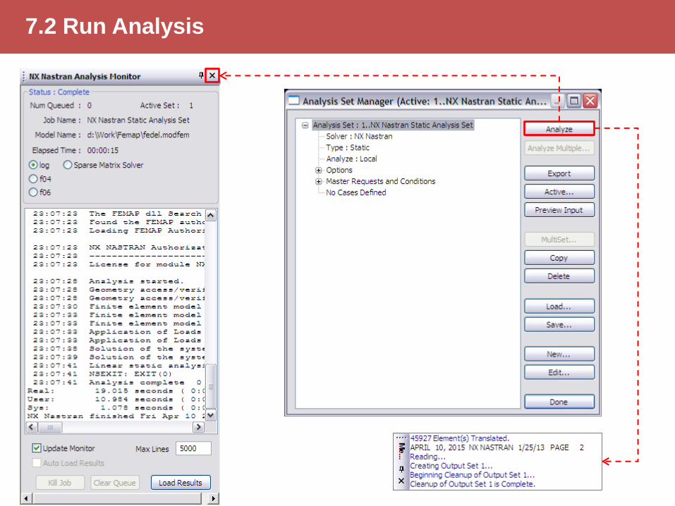
7.2 Run Analysis

8.1 Results – Select Deformed and Contour Data
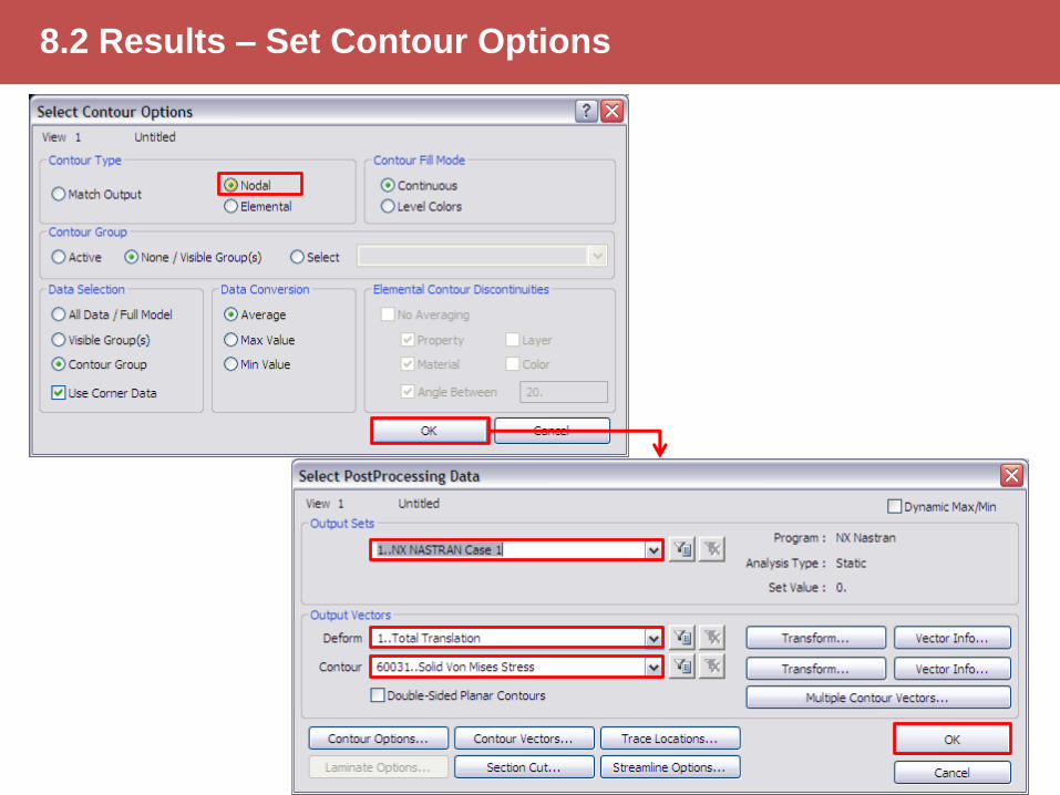
8.2 Results – Set Contour Options
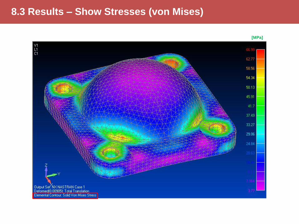
8.3 Results – Show Stresses (von Mises)
[MPa]
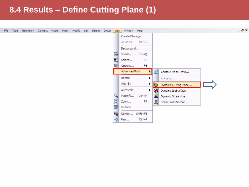
8.4 Results – Define Cutting Plane (1)
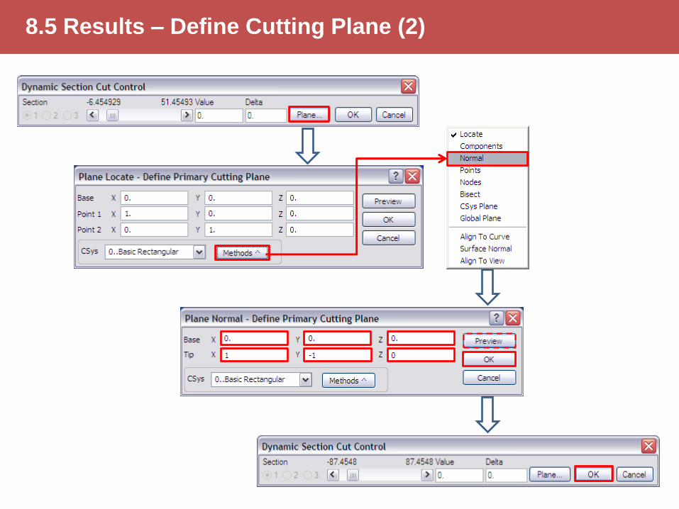
8.5 Results – Define Cutting Plane (2)
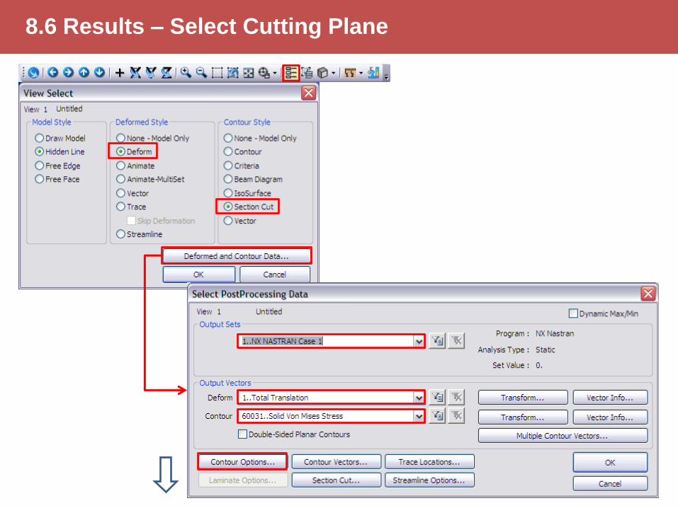
8.6 Results – Select Cutting Plane

8.7 Results – Set Contour Options

8.8 Results – Show Stresses (von Mises) (Cut)
[MPa]

9.1 Global Remeshing – Delete Old Mesh (1)
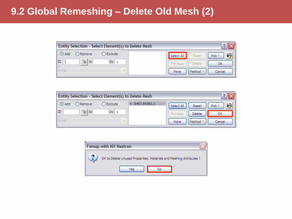
9.2 Global Remeshing – Delete Old Mesh (2)
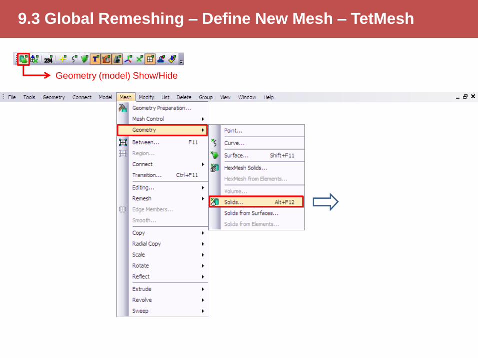
9.3 Global Remeshing – Define New Mesh – TetMesh
Geometry (model) Show/Hide
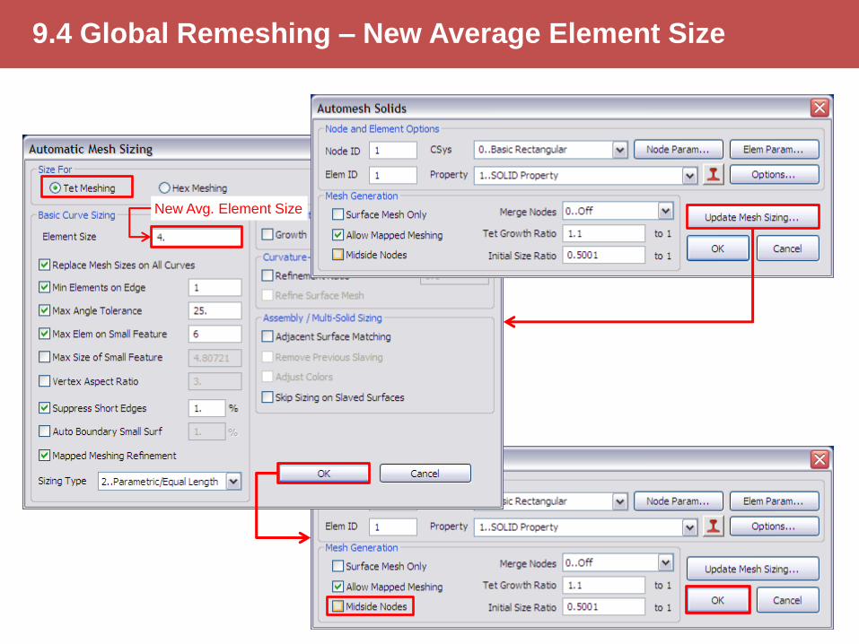
9.4 Global Remeshing – New Average Element Size
New Avg. Element Size
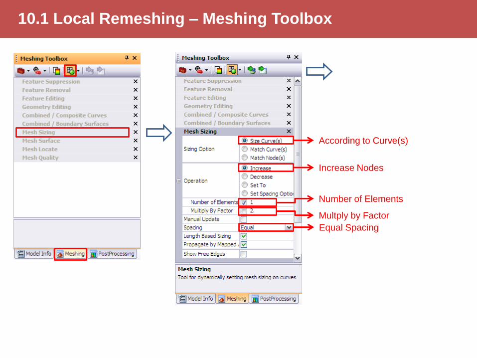
10.1 Local Remeshing – Meshing Toolbox
According to Curve(s)
Increase Nodes
Multply by Factor
Number of Elements
Equal Spacing
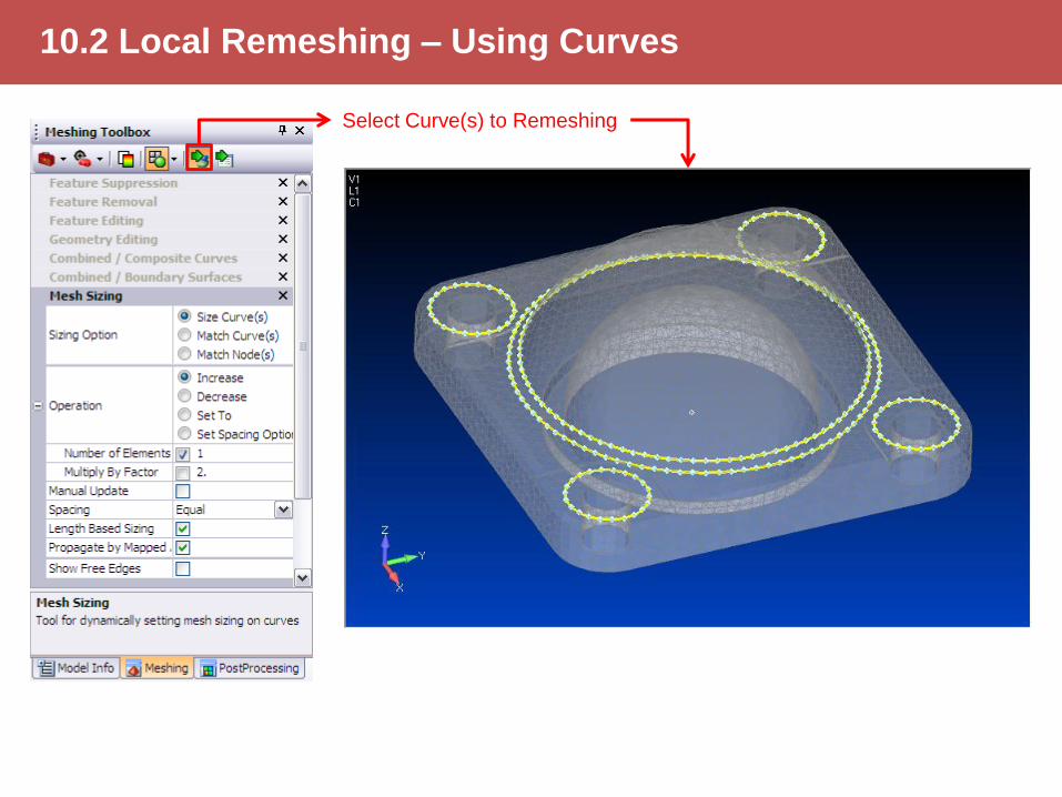
10.2 Local Remeshing – Using Curves
Select Curve(s) to Remeshing
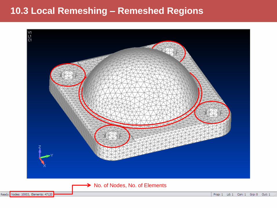
10.3 Local Remeshing – Remeshed Regions
No. of Nodes, No. of Elements
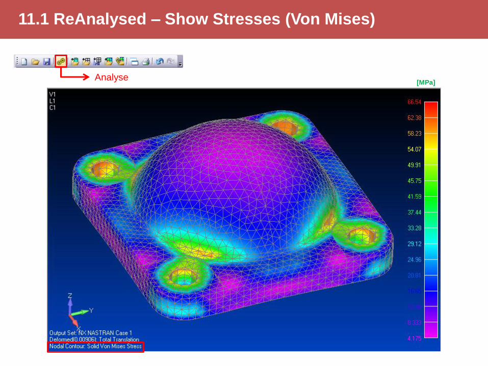
11.1 ReAnalysed – Show Stresses (Von Mises)
Analyse [MPa]
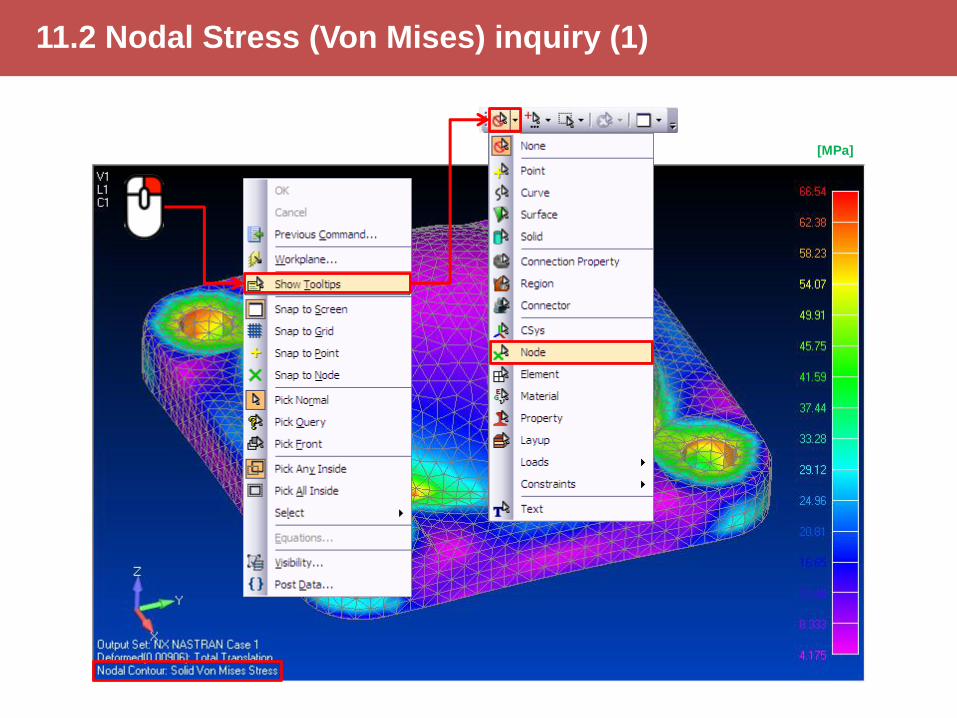
11.2 Nodal Stress (Von Mises) inquiry (1)
[MPa]
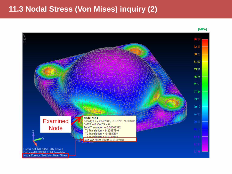
11.3 Nodal Stress (Von Mises) inquiry (2)
Examined
Node
[MPa]

12.1 Convergence Curve – Overview
Steps to Convergence Curve:
1. Designate an examined point (preferably geometric point)
2. Meshing + Analyze Note the number of Elements (E) and
Stress () at the test point (Node)
3. Refine mesh + Analyze (with unchanged boundary conditions)
Note the number of Elements (E) and Stress () at the test point
(Node)
4. Repeat the step 3 as often as necessary
5. Plot the corresponding number of Elements and Stress pairs in
the E- coordinate system
6. Fit the convergence curve to the points
7. The asymptote of the fitted curve will be the accepted Stress

No. of Elements (E)
Von Mises
Stress
[MPa]
Mesh4; E=15312 Mesh5; E=21983 Mesh3; E=11734 Mesh2; E=8664 Mesh1; E=6715
xceba)x(f
a = 77.567249
b = 599.61779
c = 0.00049989295
Convergence-curve
red,1=56.5 MPa
red,2=70.3 MPa
red,5=78.7 MPa
red,3=75.1 MPa
~78 MPa
1
2
3
4
5
1
2
3 4
5
red,4=76.4 MPa
12.2 Convergence Curve – Plot
Examined Node
Accepted range

THE END

Connection rod Buckling Analysis
Femap v11 Example
By János DEVECZ
(2017)
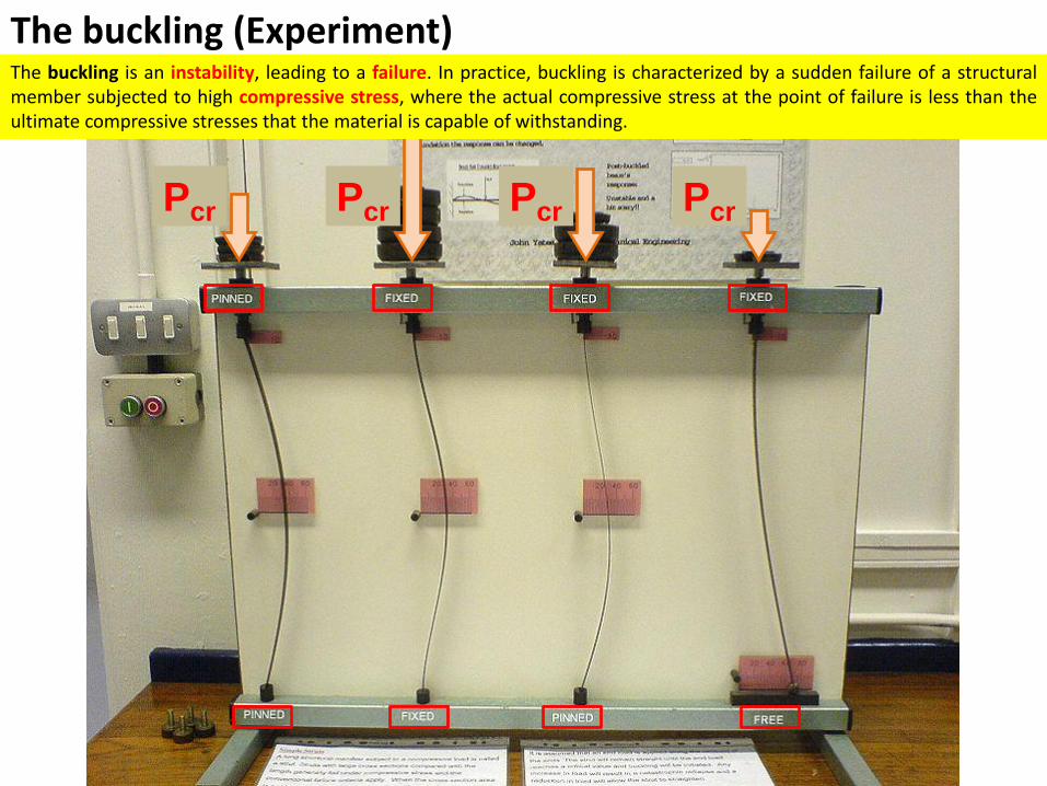
Pcr
The buckling (Experiment) The buckling is an instability, leading to a failure. In practice, buckling is characterized by a sudden failure of a structural member subjected to high compressive stress, where the actual compressive stress at the point of failure is less than the ultimate compressive stresses that the material is capable of withstanding.
Pcr Pcr Pcr
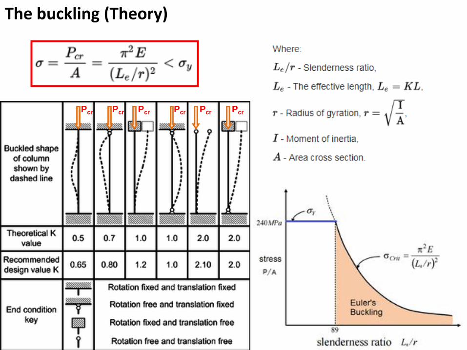
The buckling (Theory)
Pcr Pcr Pcr Pcr Pcr Pcr
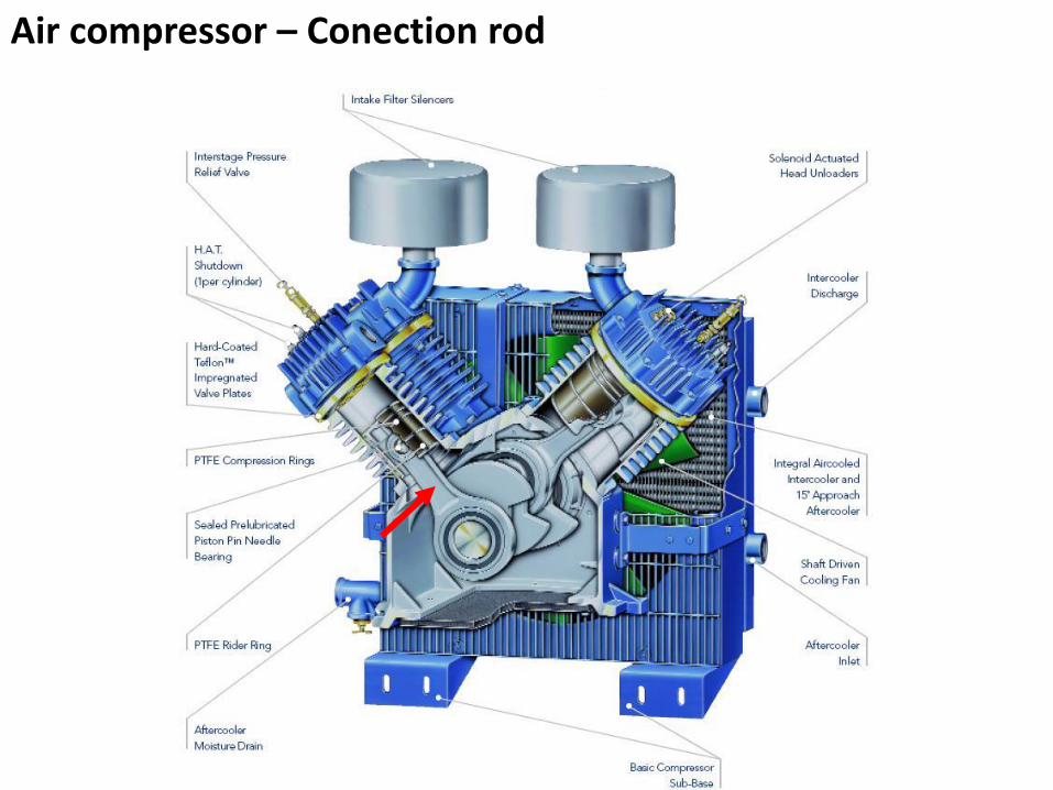
Air compressor – Conection rod
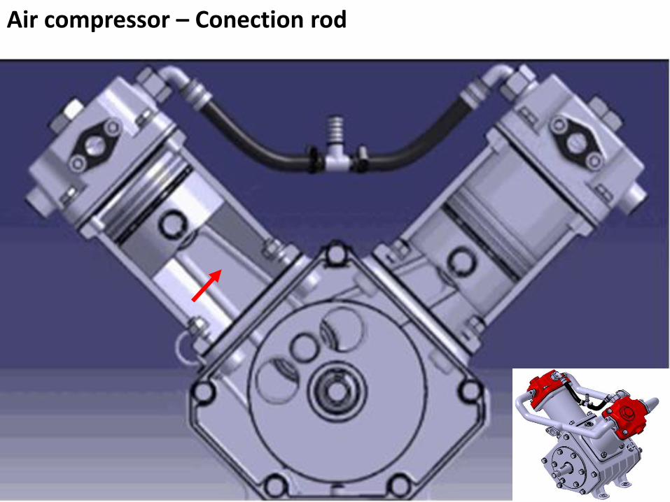
Air compressor – Conection rod

Connection rod (3D model)
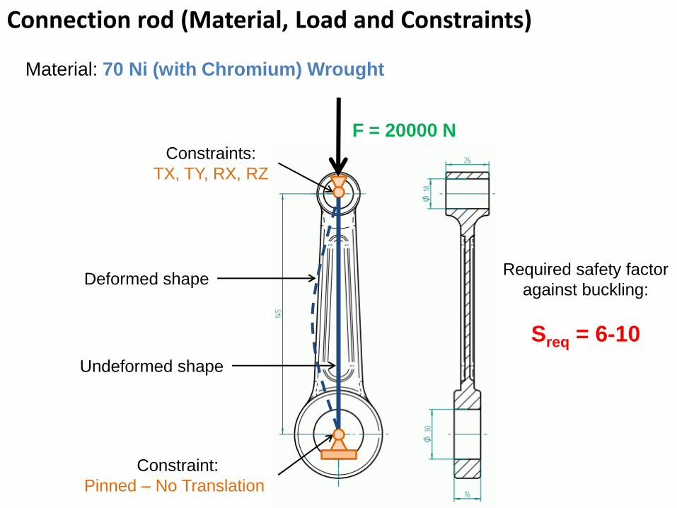
Connection rod (Material, Load and Constraints)
F = 20000 N
Constraints:
TX, TY, RX, RZ
Required safety factor
against buckling:
Sreq = 6-10
Deformed shape
Undeformed shape
Constraint:
Pinned – No Translation
Material: 70 Ni (with Chromium) Wrought

THE END

Crankshaft Modal Analysis
Femap v11 Example
By János DEVECZ
(2017)
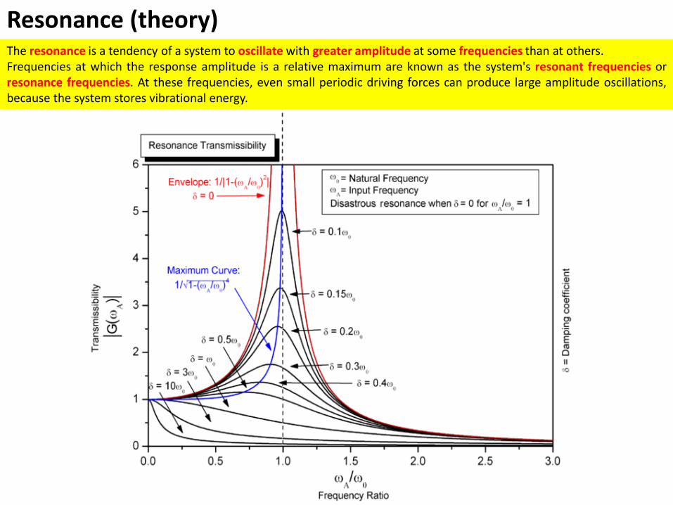
The resonance is a tendency of a system to oscillate with greater amplitude at some frequencies than at others. Frequencies at which the response amplitude is a relative maximum are known as the system's resonant frequencies or resonance frequencies. At these frequencies, even small periodic driving forces can produce large amplitude oscillations, because the system stores vibrational energy.
Resonance (theory)
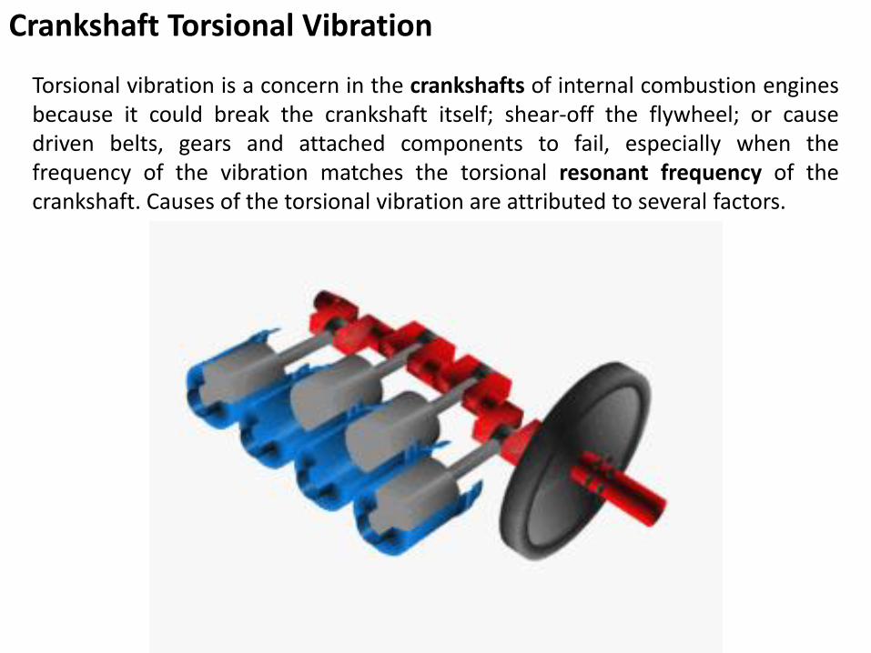
Crankshaft Torsional Vibration
Torsional vibration is a concern in the crankshafts of internal combustion engines because it could break the crankshaft itself; shear-off the flywheel; or cause driven belts, gears and attached components to fail, especially when the frequency of the vibration matches the torsional resonant frequency of the crankshaft. Causes of the torsional vibration are attributed to several factors.
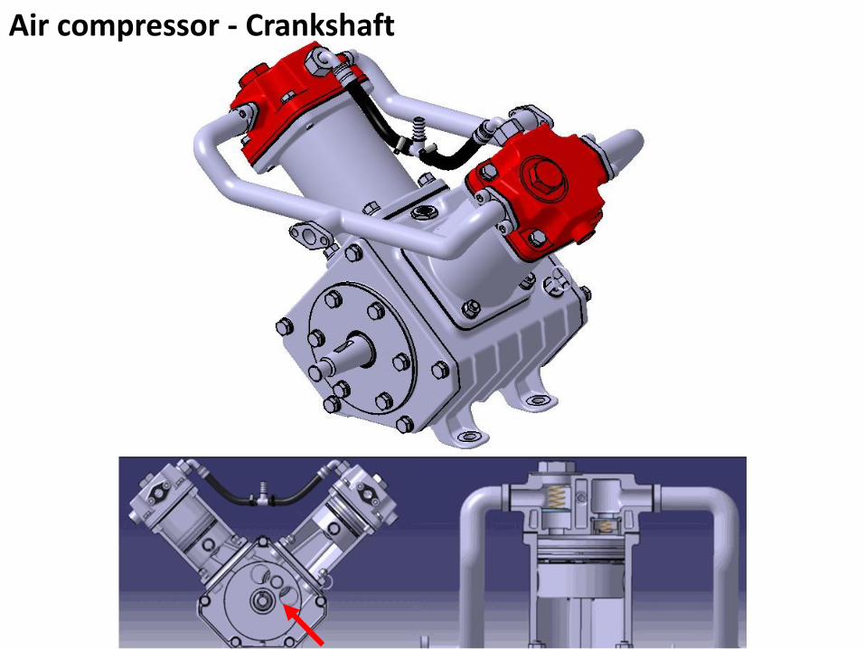
Air compressor - Crankshaft
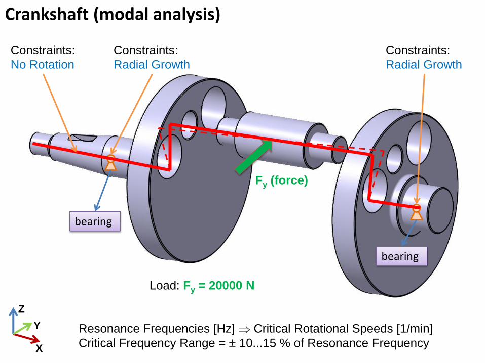
Crankshaft (modal analysis)
bearing
bearing
Load: Fy = 20000 N
Constraints:
Radial Growth
Fy (force)
X
Y
Z
Resonance Frequencies [Hz] Critical Rotational Speeds [1/min]
Critical Frequency Range = 10...15 % of Resonance Frequency
Constraints:
Radial Growth
Constraints:
No Rotation

THE END

1
Shaft FEM Analysis (Bending & Torsion)
By János DEVECZ
(2017)
Femap v11 Example
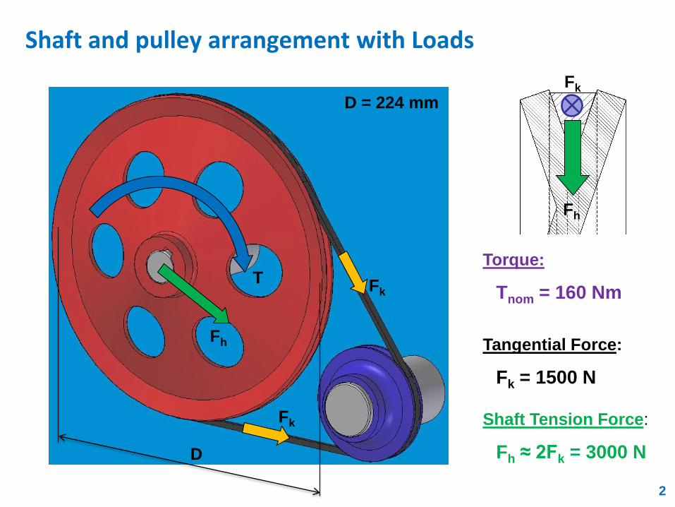
Shaft and pulley arrangement with Loads
Fh
Fk
T
Fh
D
D = 224 mm
Fk
Torque:
Tnom = 160 Nm
Fk
2
Tangential Force:
Fk = 1500 N
Shaft Tension Force:
Fh ≈ 2Fk = 3000 N
Tnom
Fh
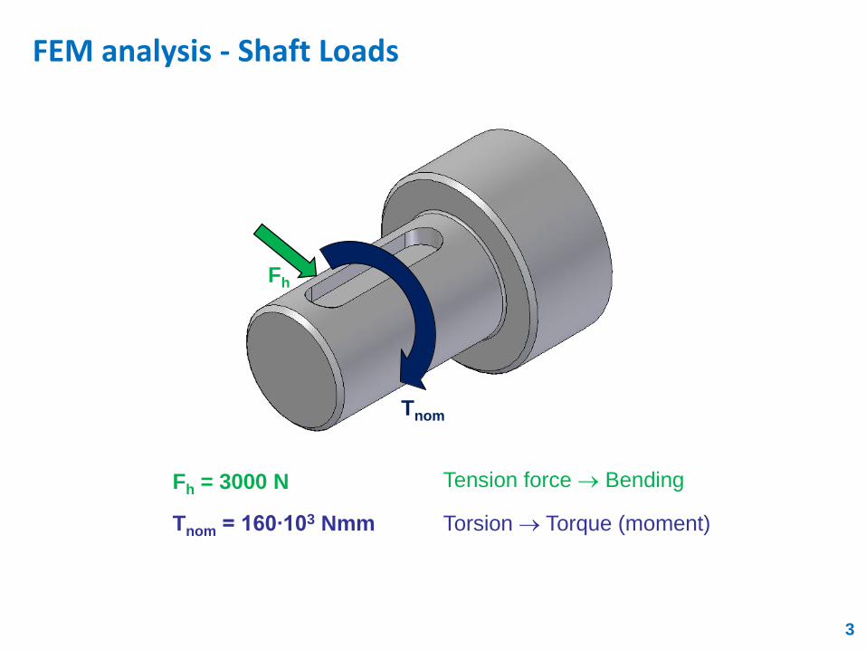
Fh = 3000 N
Tnom = 160∙103 Nmm Torsion Torque (moment)
FEM analysis - Shaft Loads
3
Tension force Bending
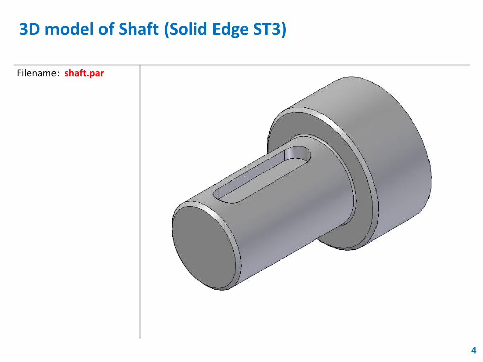
3D model of Shaft (Solid Edge ST3)
Filename: shaft.par
4
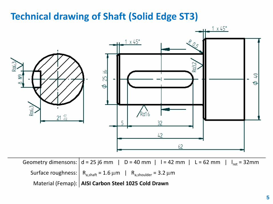
Geometry dimensons:
Surface roughness:
Material (Femap):
d = 25 j6 mm | D = 40 mm | l = 42 mm | L = 62 mm | lret = 32mm
Ra,shaft = 1.6 mm | Ra,shoulder = 3.2 mm
AISI Carbon Steel 1025 Cold Drawn
Technical drawing of Shaft (Solid Edge ST3)
5
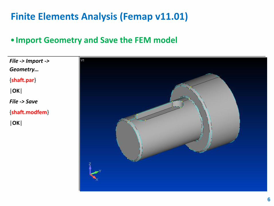
Finite Elements Analysis (Femap v11.01)
6
File -> Import ->
Geometry…
{shaft.par}
|OK|
File -> Save
{shaft.modfem}
|OK|
• Import Geometry and Save the FEM model
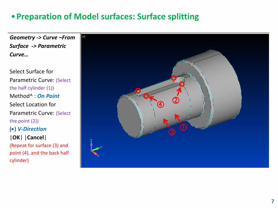
Geometry -> Curve –From
Surface -> Parametric
Curve…
Select Surface for
Parametric Curve: (Select
the half cylinder (1))
Method^ : On Point
Select Location for
Parametric Curve: (Select
the point (2))
() V-Direction
|OK| |Cancel|
(Repeat for surface (3) and
point (4), and the back half
cylinder)
7
•Preparation of Model surfaces: Surface splitting
8
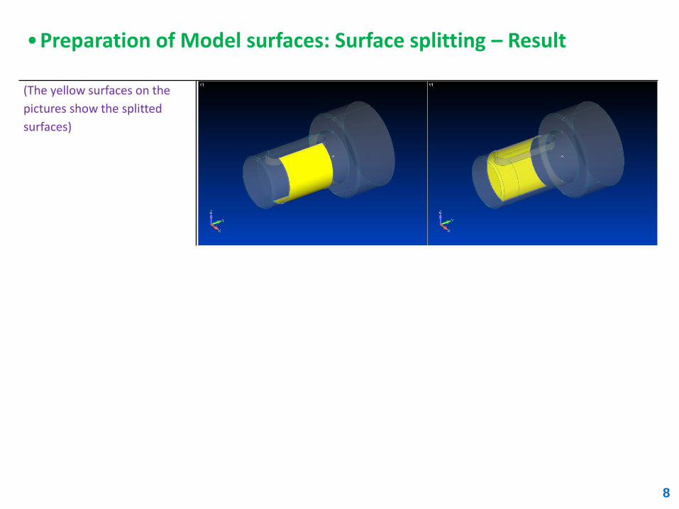
(The yellow surfaces on the
pictures show the splitted
surfaces)
•Preparation of Model surfaces: Surface splitting – Result

•Meshing the Geometric model
Mesh -> Geometry ->
Solids…
Material: AISI Carbon Steel
1025 Cold Drawn
|OK|
Midside Nodes [<NO>]
|Update Mesh Sizing…|
Element Size: [3]
|OK|
9
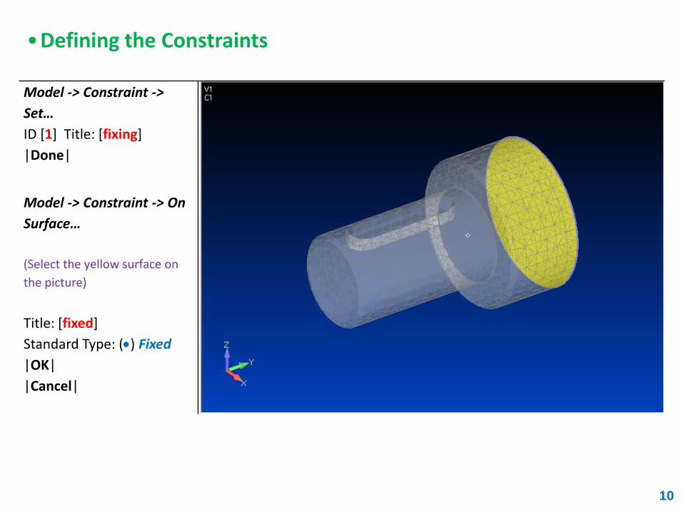
•Defining the Constraints
Model -> Constraint ->
Set…
ID [1] Title: [fixing]
|Done|
Model -> Constraint -> On
Surface…
(Select the yellow surface on
the picture)
Title: [fixed]
Standard Type: () Fixed
|OK|
|Cancel|
10
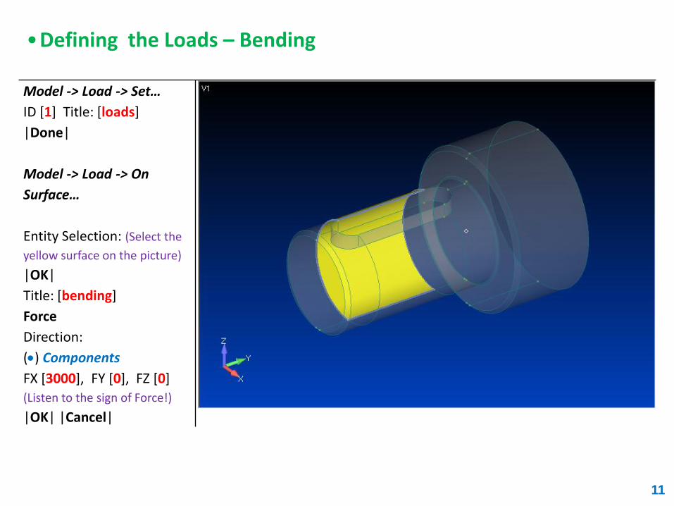
•Defining the Loads – Bending
11
Model -> Load -> Set…
ID [1] Title: [loads]
|Done|
Model -> Load -> On
Surface…
Entity Selection: (Select the
yellow surface on the picture)
|OK|
Title: [bending]
Force
Direction:
() Components
FX [3000], FY [0], FZ [0]
(Listen to the sign of Force!)
|OK| |Cancel|
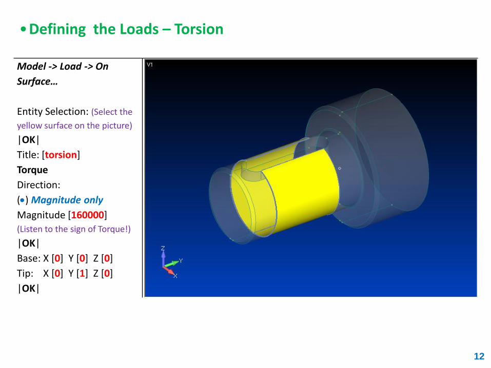
•Defining the Loads – Torsion
12
Model -> Load -> On
Surface…
Entity Selection: (Select the
yellow surface on the picture)
|OK|
Title: [torsion]
Torque
Direction:
() Magnitude only
Magnitude [160000]
(Listen to the sign of Torque!)
|OK|
Base: X [0] Y [0] Z [0]
Tip: X [0] Y [1] Z [0]
|OK|
13
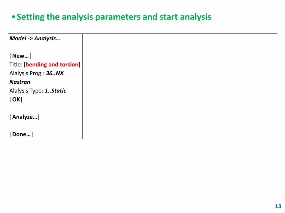
Model -> Analysis…
|New…|
Title: [bending and torsion]
Alalysis Prog.: 36..NX
Nastran
Alalysis Type: 1..Static
|OK|
|Analyze…|
|Done…|
•Setting the analysis parameters and start analysis
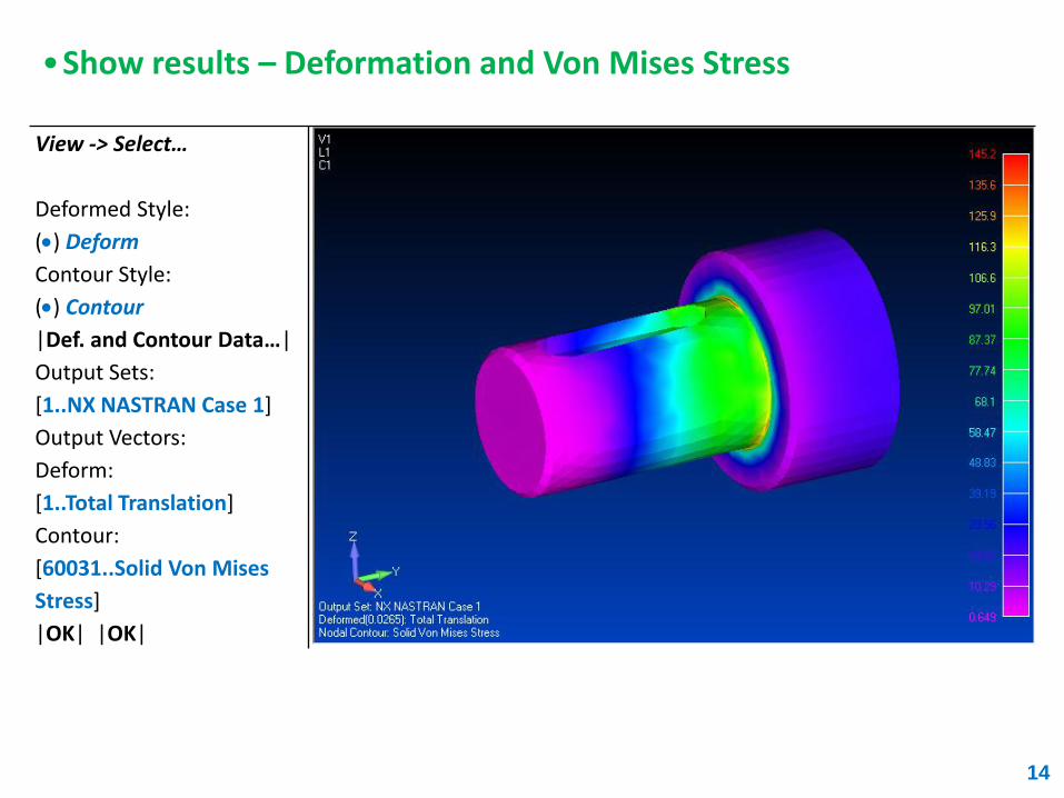
•Show results – Deformation and Von Mises Stress
14
View -> Select…
Deformed Style:
() Deform
Contour Style:
() Contour
|Def. and Contour Data…|
Output Sets:
[1..NX NASTRAN Case 1]
Output Vectors:
Deform:
[1..Total Translation]
Contour:
[60031..Solid Von Mises
Stress]
|OK| |OK|

15
THE END