feasibilty for the project.docx
TRANSCRIPT

7/28/2019 Feasibilty for the project.docx
http://slidepdf.com/reader/full/feasibilty-for-the-projectdocx 1/18
SIR WILLIAM CROOKS addressed the problem and concluded with the words: “ It is the
chemist who must come to the rescue of the threatened communities. It is through the
laboratory that starvation may ultimately be turned into plenty. Before we are in the grip of
actual dearth the chemist will step in and postpone the days of famine to so distant a period
that we, our sons and grandsons may live without undue solicitude for the future.”
Ammonia is one of the largest 5 commodities of chemical industry. Where there is
nitrogen required for chemical production it comes from Ammonia. 15% of the
chemical industry commodity is fulfilled through Ammonia.
Synthetic ammonia produced from reaction between nitrogen and hydrogen is the base
from which virtually all nitrogen-containing products are derived.
Fixed nitrogen from the air is the major ingredient of fertilizers which makes intensive food
production possible. During the development of inexpensive nitrogen fixation processes,
many principles of chemical and high-pressure processes were clarified and the field of
chemical engineering emerged.
Present Scenario: (Need of the Day)
Non supply of gas to Fertilizer Sector is hurting farmers as well as agriculture sector of
economy besides causing maximum urea price hike. Higher input costs and lower produce
prices have started crippling farming community. Fertilizer expenses saw the maximum
increase among all inputs during last year. Pakistani industries which produce ammonia
1. Engro Fertilizers
2. Fauji Fertilizers
3. Agri Tech
4. Dawood Hercules
5. Reliance Group
6. National Fertilizer Marketing Ltd
Ammonia Synthesis: A Brief over view can be as follow:
1. Different feed stocks available and cost comparison.
2. Technology wise discussion
3. Selection of feed stock
4. Cost estimation
5. Selection of the Process on the behalf of the above stated discussion.

7/28/2019 Feasibilty for the project.docx
http://slidepdf.com/reader/full/feasibilty-for-the-projectdocx 2/18
Progress in Ammonia synthesis can be divided into 3 phases
1. Haber Era
2.
Development in Catalyst.3. Future Prospectus
Haber’s Contributions to Ammonia Synthesis Process
Haber recognized that much higher pressures had to be employed and he constructed a small
laboratory apparatus for the continuous production of ammonia. Haber’s recycle idea
changed the previously static conception of process engineering in favor of a more dynamic
approach.
Schematic of re-cycle apparatus used by Haber for ammonia synthesis
The amount of ammonia formed in a single gas pass is much too small to be of interest for
the economic production of ammonia. Haber, therefore, recycled his gas over the catalyst
after separating the ammonia formed by condensation. The gas lost by conversion was
compensated with a fresh gas input and the mixture was recycled under pressure. This
process became the basis for the technical manufacture of ammonia. Since then, the same
principle has found widespread application for numerous high-pressure reactions in the
organic chemistry sector. Haber’s recycle idea changed the previously static conception of
process engineering in favor of a more dynamic approach. For the first time, reaction
kinetics as well as the thermodynamics of the system was being considered. In addition tochemical equilibrium, Haber recognized that reaction rate was a determining factor in this

7/28/2019 Feasibilty for the project.docx
http://slidepdf.com/reader/full/feasibilty-for-the-projectdocx 3/18
problem. Instead of simple reaction yield, he concentrated on space-time yield, that is, the
amount of ammonia obtained per unit volume of the catalyst per unit time (Figure 3).In this
manner it became apparent that the real problem was to find a suitable catalyst so that the
maximum amount of product is obtained with minimum volume of the catalyst in the shortest
time possible, that is, space time yield needs to be maximized. Early in 1909, Haber discovered in finely distributed osmium, a catalyst which yielded 8% ammonia at 175 bar and
about 600°C. He also established that uranium could be used as a catalyst. Haber constructed
a new laboratory plant which could be operated according to his recycle concept (Figure4).
With this equipment, he demonstrated the production of 80 g of ammonia/ hr in July 1909.
The catalysts which Haber initially employed were too expensive and unstable to be used in
commercial processes. Systematic investigations covering virtually the en-tire periodic table
by Haber, Metcash and coworkers at BASF for next two years resulted in solution to the
catalyst problem.
In early units the reactor was heated externally, by gas burners, although this had thedisadvantage of further weakening the shell.
• A special air burner at the top of the catalyst bed could increase the gas temperature and
was used until 1922, despite the poisoning effect of water on the catalyst.
• Larger reactors only used a gas heater at start-up with reverse gas flow to avoid catalyst
poisoning.
• From 1920 better steel alloys that resisted embrittlement
became available.
By 1925, new reactors had been developed by usingimproved chromium vanadium steel alloys and internal heat
exchangers. The outer shell was protected from overheating
by passing the cold synthesis gas down the annular space
between the shell and the catalyst basket as it entered the
vessel. A typical plant was operated with the catalyst
temperature in the range 500 0 – 6500 C and at a higher
pressure, up to 300 – 350 atm, which allowed higher
conversion and easier ammonia removal by water scrubbing.
While these conditions should give a theoretical conversion
in the range 8 – 11%, the actual conversion was only 7 – 9%.
A reactor, producing 20 tons .day of ammonia weighedabout 70 tones, was 12 m long, and held a basket of 80 cm
internal diameter. It took about 3 days to change a
deactivated catalyst and restart operation. In those days, in
order to increase production, typical ammonia plants
operated with several small reactors rather than a single
large one.
The production of ammonia during the early 1900s stimulated the increasing use of industrial
catalysts. Development of the synthesis catalyst set a pattern for all other catalysts
subsequently used in chemical and refining processes. Theoretical and experimental effort
had shown that the process was feasible. This was followed by the development of practicalequipment and full scale operation. A relatively cheap and reliable catalyst was thoroughly
7/28/2019 Feasibilty for the project.docx
http://slidepdf.com/reader/full/feasibilty-for-the-projectdocx 4/18
tested and Produced economically in what were then large volumes. Finally, both the process
and catalyst were gradually improved as the scale of operation expanded.
The pioneering work of Haber, Bosch, and Metcash led to a process which has survived in
more or less the same form as it is used today. Their achievement led to the introduction of
chemical engineering, high pressure technology and consolidated the ideas of unit processes. New materials were developed for use with hydrogen at high pressures.
Process Development
Today the term “ammonia synthesis” is increasingly used when referring to the total
ammonia production process. Synthesis conditions are no longer viewed in isolation. Of
course, they are an important consideration in the total process but can be determined
properly only in relation to the total plant integration.
The complete process of industrial ammonia production may be subdivided into the following
sections:
1. Raw synthesis Feed gas purification
a. Desulfurization (by hydro-treating and absorption)
b. Reforming (primary and secondary) as well as Pre-reforming.
c. Carbon monoxide (CO) shifts to carbon dioxide.
2. Synthesis Feed gas purification
a. CO2 removal by Absorption. Conversion of CO and trace amounts of CO2 (Total
Oxides) by Methanation.
3. Liquid Ammonia Synthesis ( Production)
a. Compression of synthesis feed gas.
b. Synthesis (conversion) of syn. Gaas to ammonia.
c. Separation of liquid ammonia from the syn. Gas loop (chilling).
4. Removal of Light ends (Low Pressure flash and Re-Flashing.
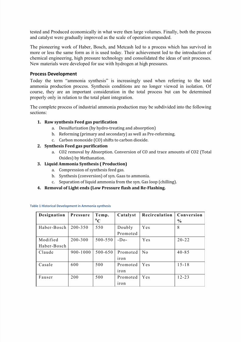
Table 1 Historical Development in Ammonia synthesis
Designation Pressure Temp.0C
Catalyst Recirculation Conversion
%
Haber-Bosch 200-350 550 Doubly
Promoted
Yes 8
ModifiedHaber-Bosch
200-300 500-550 -Do- Yes 20-22
Claude 900-1000 500-650 Promoted
iron
No 40-85
Casale 600 500 Promoted
iron
Yes 15-18
Fauser 200 500 Promoted
iron
Yes 12-23
7/28/2019 Feasibilty for the project.docx
http://slidepdf.com/reader/full/feasibilty-for-the-projectdocx 5/18
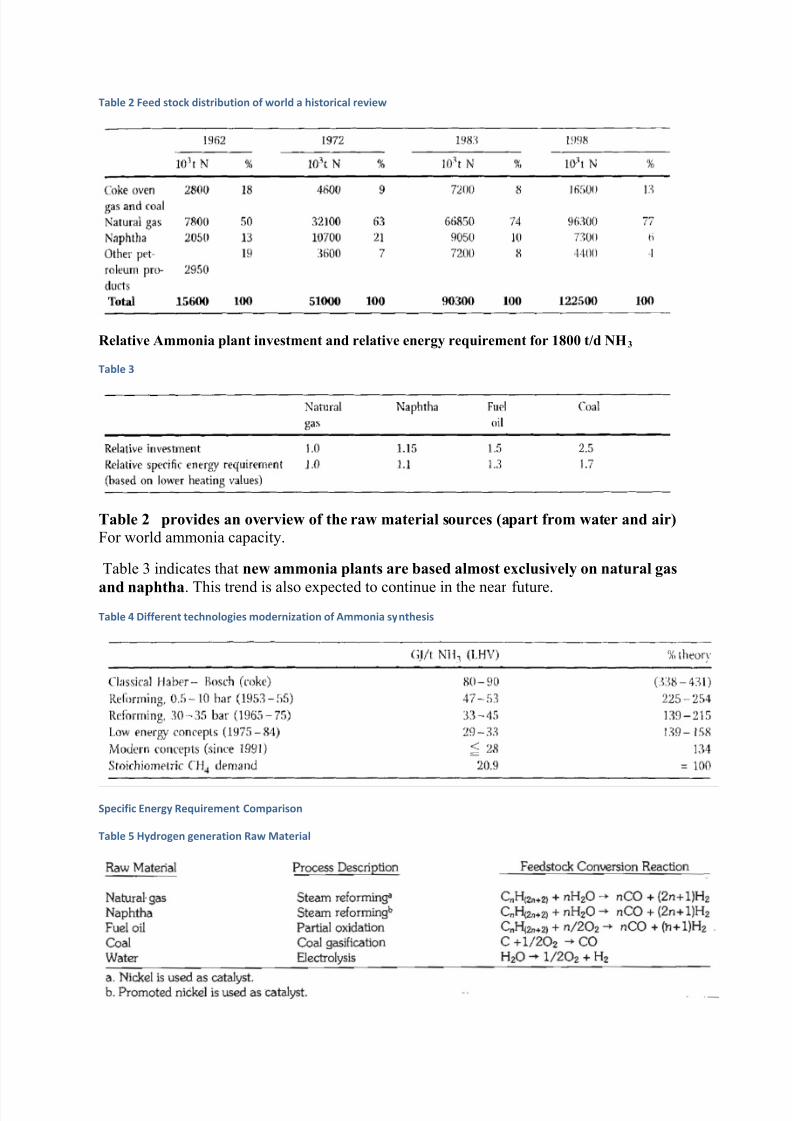
Table 2 Feed stock distribution of world a historical review
Relative Ammonia plant investment and relative energy requirement for 1800 t/d NH3
Table 3
Table 2 provides an overview of the raw material sources (apart from water and air)
For world ammonia capacity.
Table 3 indicates that new ammonia plants are based almost exclusively on natural gas
and naphtha. This trend is also expected to continue in the near future.
Table 4 Different technologies modernization of Ammonia synthesis
Specific Energy Requirement Comparison
Table 5 Hydrogen generation Raw Material
7/28/2019 Feasibilty for the project.docx
http://slidepdf.com/reader/full/feasibilty-for-the-projectdocx 6/18
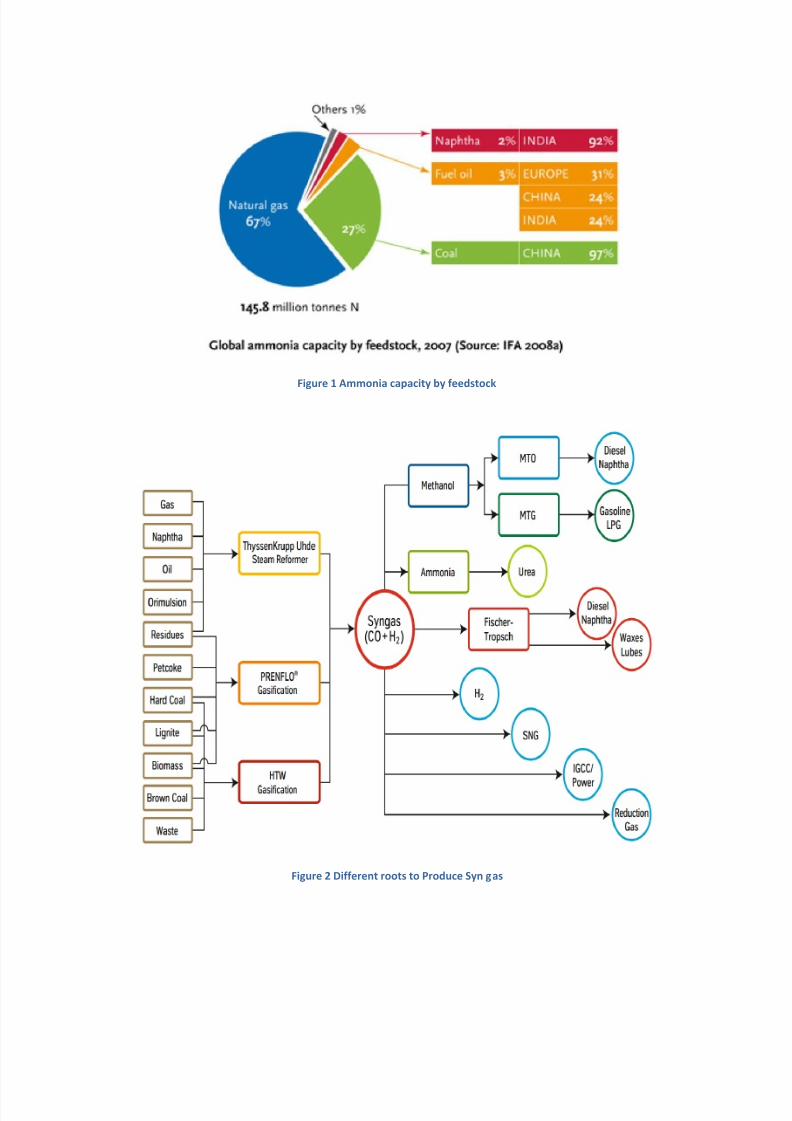
Figure 1 Ammonia capacity by feedstock
Figure 2 Different roots to Produce Syn gas
7/28/2019 Feasibilty for the project.docx
http://slidepdf.com/reader/full/feasibilty-for-the-projectdocx 7/18
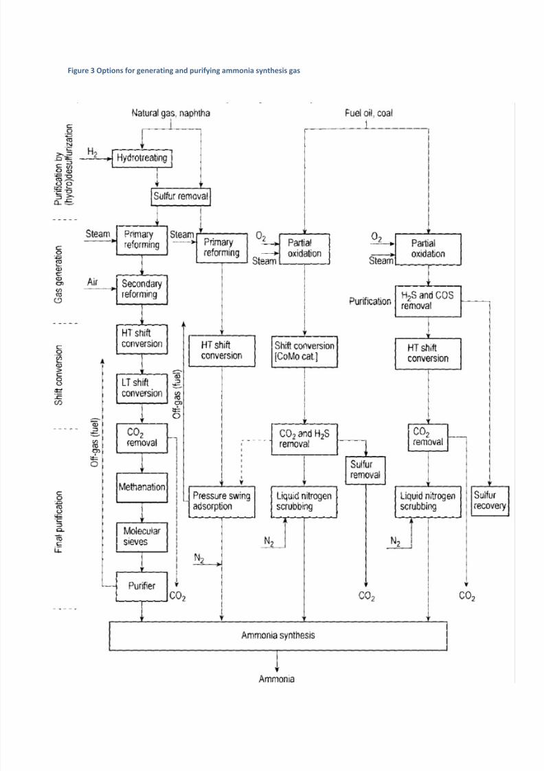
Figure 3 Options for generating and purifying ammonia synthesis gas
7/28/2019 Feasibilty for the project.docx
http://slidepdf.com/reader/full/feasibilty-for-the-projectdocx 8/18
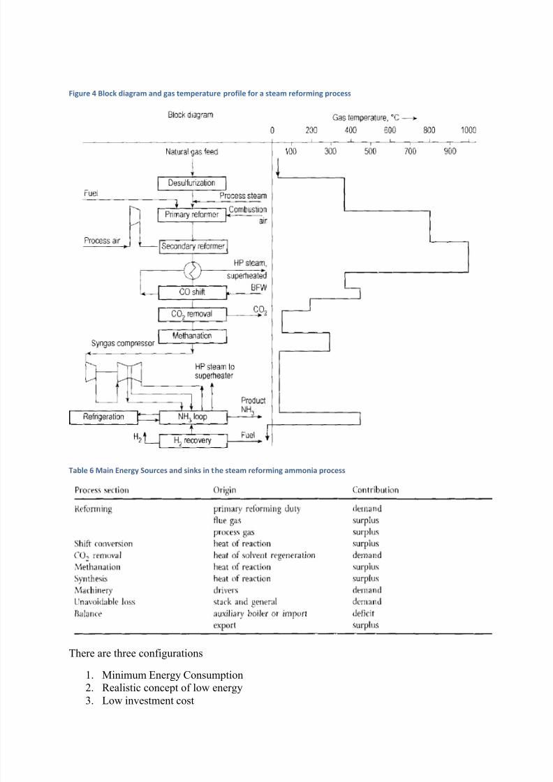
Figure 4 Block diagram and gas temperature profile for a steam reforming process
Table 6 Main Energy Sources and sinks in the steam reforming ammonia process
There are three configurations
1. Minimum Energy Consumption
2. Realistic concept of low energy3. Low investment cost
7/28/2019 Feasibilty for the project.docx
http://slidepdf.com/reader/full/feasibilty-for-the-projectdocx 9/18
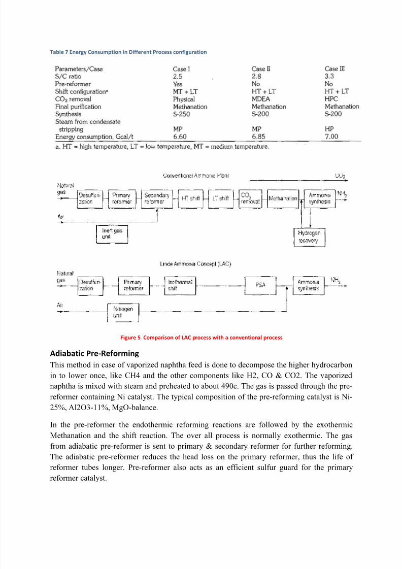
Table 7 Energy Consumption in Different Process configuration
Figure 5 Comparison of LAC process with a conventional process
Adiabatic Pre-Reforming
This method in case of vaporized naphtha feed is done to decompose the higher hydrocarbon
in to lower once, like CH4 and the other components like H2, CO & CO2. The vaporized
naphtha is mixed with steam and preheated to about 490c. The gas is passed through the pre-
reformer containing Ni catalyst. The typical composition of the pre-reforming catalyst is Ni-25%, Al2O3-11%, MgO-balance.
In the pre-reformer the endothermic reforming reactions are followed by the exothermic
Methanation and the shift reaction. The over all process is normally exothermic. The gas
from adiabatic pre-reformer is sent to primary & secondary reformer for further reforming.
The adiabatic pre-reformer reduces the head loss on the primary reformer, thus the life of
reformer tubes longer. Pre-reformer also acts as an efficient sulfur guard for the primary
reformer catalyst.
7/28/2019 Feasibilty for the project.docx
http://slidepdf.com/reader/full/feasibilty-for-the-projectdocx 10/18
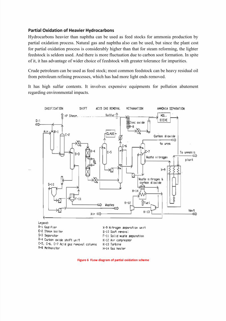
Partial Oxidation of Heavier Hydrocarbons
Hydrocarbons heavier than naphtha can be used as feed stocks for ammonia production by
partial oxidation process. Natural gas and naphtha also can be used, but since the plant cost
for partial oxidation process is considerably higher than that for steam reforming, the lighter
feedstock is seldom used. And there is more fluctuation due to carbon soot formation. In spiteof it, it has advantage of wider choice of feedstock with greater tolerance for impurities.
Crude petroleum can be used as feed stock; most common feedstock can be heavy residual oil
from petroleum refining processes, which has had more light ends removed.
It has high sulfur contents. It involves expensive equipments for pollution abatement
regarding environmental impacts.
Figure 6 FLow diagram of partial oxidation scheme
7/28/2019 Feasibilty for the project.docx
http://slidepdf.com/reader/full/feasibilty-for-the-projectdocx 11/18
New Catalyst Developments
At the stage of development of the ammonia synthesis reaction as described in the previous
sections, the main problem was the low level of conversion of synthesis gas to ammonia .
This could be increased by operation at yet higher pressure, but this would not be cost
effective. The other option would be to operate at lower temperature, under which conditions,the equilibrium concentration of ammonia would be appreciably higher. Unfortunately, the
catalysts available at the time were not sufficiently active to operate at the lower temperature
required to make a meaningful difference to the concentration of ammonia in the product gas,
and hence a significant difference to the economics of the process. Any real improvement to
the process was therefore dependent upon the development of a new catalyst with
significantly improved activity. The clear target would be a catalyst with sufficient activity to
give a satisfactory level of conversion at the same pressure as that within the reformer.
The surface area of the ammonia synthesis catalyst is only about 1 – 2 m 2 g -1 . It was known
from experience with other catalysts that precipitation from aqueous solution always led to a product with a much higher surface area than one prepared by fusion, and therefore
potentially at least, more active sites per unit weight of catalyst. This process route was
studied in ICI, initially by Topsham. Subsequent developments led to the preparation and
testing of a precipitated catalyst containing cobalt which showed levels of activity
approximately 3 fold higher that of the best conventional catalyst available at the time.
Ammonia could be synthesized at temperatu res below 350ºC , but the catalyst was not
commercialized for several reasons. The major reason was that the pelleted oxide was
signi f icantly weakened dur ing the reduction procedure, and became too weak to withstand
the rigours of an axial f low converter. I t also suf fered fr om shr inkage dur ing reduction,
leading to settl ing of the bed, and the li kely development of hot-spot s.
The announcement in 1979 by BP of a ruthenium catalyst was the first real advance in
improving the process. The catalyst was more active and operated at a lower temperature to
produce a higher equilibrium ammonia concentration. A relatively high operating pressure
was still needed, however, when using a bed charged with Ru catalyst in conjunction with
other beds containing magnetite catalysts. The catalyst was reversibly poisoned by some of
the impurities pre-sent in typical synthesis gas.
The new ruthenium catalyst converter was in series with the old converter. Although in 1992
there was no additional synthesis gas to increase production capacity, the ruthenium catalyst
operated well in a radial flow reactor and reduced both the steam and electricity used by 30-
40% and 5-10% respectively. The new catalyst was said to be twenty times as active as the
iron catalyst, and the effluent gas contained about 20% ammonia.
Other large ammonia plants are now using single beds of the ruthenium catalyst in
conjunction with the magnetite catalyst. They confirm the higher activity of ruthenium, with
the benefits of a lower operating pressure and temperature, while maintaining a high
concentration of ammonia in the exit gas. For future process designs, the need for less gas
compression and less high-pressure equipment will lead to lower operating and capital costs.

7/28/2019 Feasibilty for the project.docx
http://slidepdf.com/reader/full/feasibilty-for-the-projectdocx 12/18
Two plants in Trinidad, using one bed of iron catalyst and three beds of ruthenium catalyst,
have operated for several years. It is reported that the capacity of typical 1100 tones per day
plant designs could be increased to 1850 tones per day, provided there is suf fi cient reformer
capacity.
Table 8 Introduction of Ammonia Plant catalysts and Operating life
Converter Design
The majority of early ammonia plants used adiabatic beds of catalyst or tube-cooled
converters that acted like a heat exchanger with the cold synthesis gas passing through thetubes to cool the catalyst. Tube-cooled reactors, such as those introduced by the Tennessee
Valley Authority (TVA), did not operate isothermally and the exothermic reaction led to both
axial and radial temperature profiles developing. The temperature difference depended on the
number of tubes passing through the catalyst bed. The converter design took this into ac-
count by maximizing the number of tubes although the temperature profile could only be
controlled by changing the inlet gas temperature. There were problems in loading catalyst
into the space between tubes to achieve the right packing density as well as in discharging
catalyst when it was deactivated. Large tube-cooled converters were also expensive.
Modern converters are designed with several catalyst beds in which the hot gas can be cooled
at each bed exit either by heat exchange or by the addition of cold synthesis gas, often
referred to as quench cooling Quench cooling has usually been preferred in plants using
multi-bed converters despite the disadvantage of using a larger catalyst volume and having to
by-pass some of the catalyst with a significant volume of the synthesis gas.
Problems were experienced in wide, multi-bed converters, with gas flowing axially through
the beds, because big catalyst particles were required to limit the pressure drop through the
catalyst. Since activity is inversely proportional to particle size, increased volumes of catalyst
were needed and the large reactors increased the capital cost of a plant. By designingconverters in such a way that gas flowed radially through the catalyst bed, it was possible to
7/28/2019 Feasibilty for the project.docx
http://slidepdf.com/reader/full/feasibilty-for-the-projectdocx 13/18
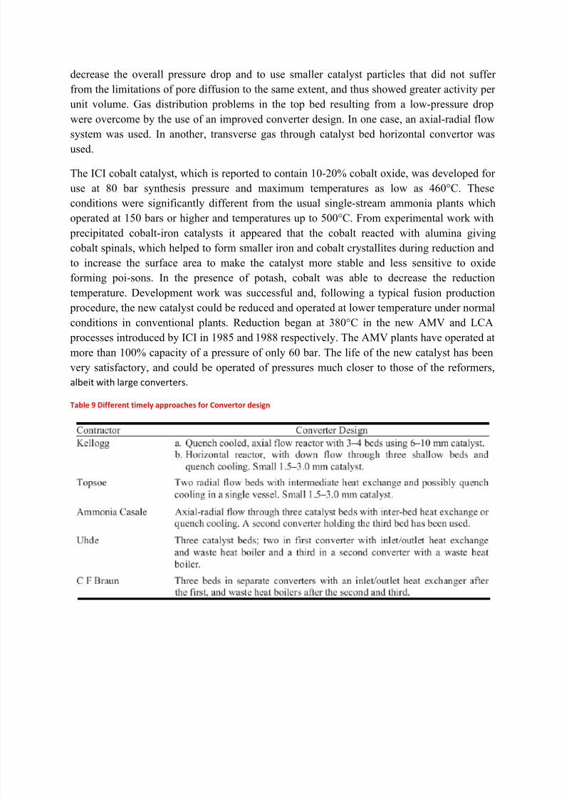
decrease the overall pressure drop and to use smaller catalyst particles that did not suffer
from the limitations of pore diffusion to the same extent, and thus showed greater activity per
unit volume. Gas distribution problems in the top bed resulting from a low-pressure drop
were overcome by the use of an improved converter design. In one case, an axial-radial flow
system was used. In another, transverse gas through catalyst bed horizontal convertor wasused.
The ICI cobalt catalyst, which is reported to contain 10-20% cobalt oxide, was developed for
use at 80 bar synthesis pressure and maximum temperatures as low as 460°C. These
conditions were significantly different from the usual single-stream ammonia plants which
operated at 150 bars or higher and temperatures up to 500°C. From experimental work with
precipitated cobalt-iron catalysts it appeared that the cobalt reacted with alumina giving
cobalt spinals, which helped to form smaller iron and cobalt crystallites during reduction and
to increase the surface area to make the catalyst more stable and less sensitive to oxide
forming poi-sons. In the presence of potash, cobalt was able to decrease the reductiontemperature. Development work was successful and, following a typical fusion production
procedure, the new catalyst could be reduced and operated at lower temperature under normal
conditions in conventional plants. Reduction began at 380°C in the new AMV and LCA
processes introduced by ICI in 1985 and 1988 respectively. The AMV plants have operated at
more than 100% capacity of a pressure of only 60 bar. The life of the new catalyst has been
very satisfactory, and could be operated of pressures much closer to those of the reformers,
albeit with large converters.
Table 9 Different timely approaches for Convertor design
7/28/2019 Feasibilty for the project.docx
http://slidepdf.com/reader/full/feasibilty-for-the-projectdocx 14/18
7/28/2019 Feasibilty for the project.docx
http://slidepdf.com/reader/full/feasibilty-for-the-projectdocx 15/18
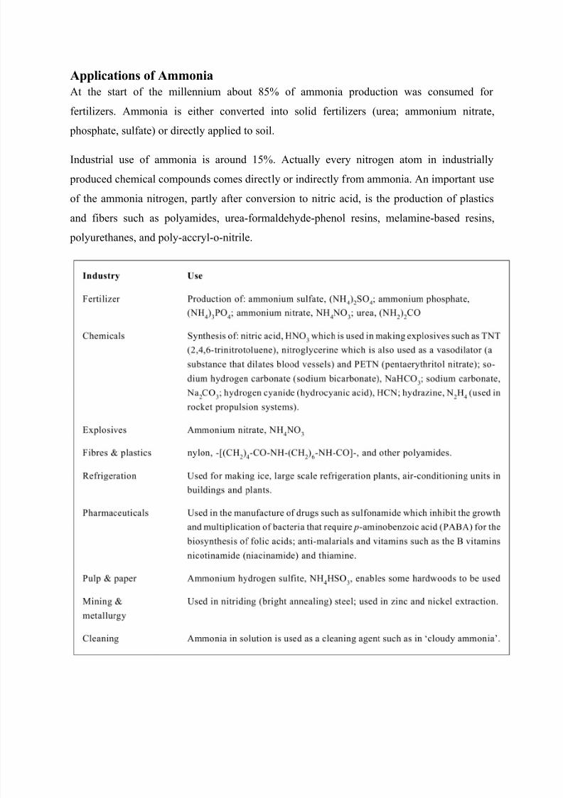
Applications of Ammonia
At the start of the millennium about 85% of ammonia production was consumed for
fertilizers. Ammonia is either converted into solid fertilizers (urea; ammonium nitrate,
phosphate, sulfate) or directly applied to soil.
Industrial use of ammonia is around 15%. Actually every nitrogen atom in industrially
produced chemical compounds comes directly or indirectly from ammonia. An important use
of the ammonia nitrogen, partly after conversion to nitric acid, is the production of plastics
and fibers such as polyamides, urea-formaldehyde-phenol resins, melamine-based resins,
polyurethanes, and poly-accryl-o-nitrile.

7/28/2019 Feasibilty for the project.docx
http://slidepdf.com/reader/full/feasibilty-for-the-projectdocx 16/18
Some examples of industrially important uses are the following reactions:
With alkyl halides or alcohols amines or imines can be manufactured. For example, methanol
forms mono-through trimethylamine, dichloromethane yields ethylene imine in the presence
of calcium oxide. Amines can also be produced by reacting ammonia with alkyl halides in
multistage process.
Environmental sector ammonia is used in various processes for removing SO2 from flue
gases of fossil-fuel power plants. The resulting ammonium sulfate is sold as fertilizer. In the
selective catalytic reduction process (SCR) the NOx in the flue gas is reduced in a catalytic
reaction of nitrogen oxide with a stoichiometric amount of Ammonia.
Figure 7
7/28/2019 Feasibilty for the project.docx
http://slidepdf.com/reader/full/feasibilty-for-the-projectdocx 17/18
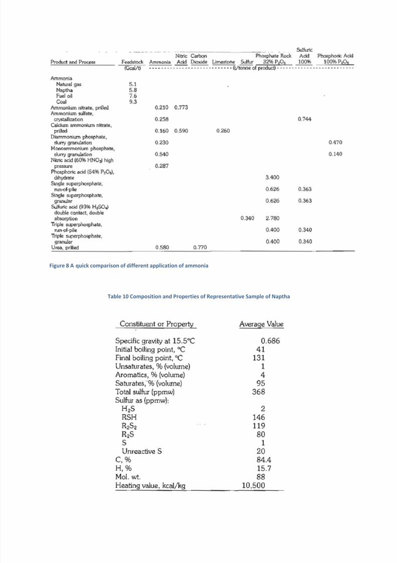
Figure 8 A quick comparison of different application of ammonia
Table 10 Composition and Properties of Representative Sample of Naptha

7/28/2019 Feasibilty for the project.docx
http://slidepdf.com/reader/full/feasibilty-for-the-projectdocx 18/18
Figure 9 Component of ammonia production
A Quick Comparison
Feed Stock
Technology Rel.Capital Investment
Feedstock Ton/ton
RelativeCost/ton
Relative EnergyConsumption
Energy(Gcal)
Lower Heating value
Natural
gas
Steam
Reforming
1 0.624 1 1 7.0 11000
Naphtha Steam
Reforming
1.15 0.720 2.5 1.1 7.6 10556
Coal Gasification 2.5 1.4 1.5 2.0 13 6000
The most suitable feedstock for the next 2 decades is surely natural gas. Naphtha due to its
high price can not be taken alone as feed stock but for some compensation and to avoid
fluctuation in the plant operation. A mixed feed of Naphtha and natural gas can be considered
as feed stock. Coal is also indigenous raw material abundantly available, but the plant taking
coal as feed stock is not self stand on the behalf of its energy requirements. About 650
Kwatt-hour extra energy is required for plant operations.
A review of ammonia production technology up to 1974 is contained in, and gives a
description of the state of the art up to 1980; the United States patent literature in the field
from 1972 to 1980 is covered in More modern and comprehensive reviews of ammonia
production technology can be found in [402]- [404]. The journal Nitrogen, published by
British Sulphur, presents an update of the state of the art from time to time. A valuable
information source is also the annual AIChE Ammonia safety symposium.