fdmi™ standard - maxrev · this proposal is to provide industry standard mounting interfaces for...
TRANSCRIPT

FDMI™ Standard VESA Video Electronics Standards Association 860 Hillview Court, Suite 150 Milpitas, California 95035
Phone: (408) 957-9270Fax: (408) 957-9277
VESA FLAT DISPLAY MOUNTING
INTERFACE STANDARD (for Flat Panel Monitors/Displays/Flat TVs)
Version 1, Rev. 1 January 16, 2006
Purpose
This proposal is to provide industry standard mounting interfaces for Flat Displays (FDs) such as flat panel monitors, flat displays and flat TVs.
Summary
This document defines mounting interfaces for Flat Displays, corresponding standards for mounting device manufacturers and cable and cable connector location guidelines. Note: Please note that the only major revisions to this Standard occur in Sections 7 and 8. Section 7, Part F of the standard was revised to accommodate all FDs greater than 90-inches diagonal. It was modified to help encourage display manufacturer compliance.

VESA Flat Display Mounting Interface Standard Version 1, Rev. 1 ©Copyright 2006 Video Electronics Standards Association i
Table of Contents
PREFACE
Intellectual Property Statement ............................................................................................... iv Trademarks .............................................................................................................................. iv Patents...................................................................................................................................... iv Other Documents Referenced .................................................................................................. iv Support For This Standard ........................................................................................................v Acknowledgements.....................................................................................................................v Revision History....................................................................................................................... vi
1 OVERVIEW......................................................................................................................... 1 1.1 General ......................................................................................................................... 1 1.2 Objectives...................................................................................................................... 1 1.3 Scope ............................................................................................................................. 1 1.4 Mounting Pad or Mounting Apparatus Design Guidelines .......................................... 3 1.5 Mounting Interface Compliance Identification/Labeling Guidelines ........................... 4 1.6 Flat Display Cable and Cable Connector Location Guidelines................................... 4 1.7 Justification................................................................................................................... 4 1.8 Features and Benefits ................................................................................................... 4 1.9 Illustrations of Various Applications Utilizing the Standard Mounting Interfaces...... 5
2 PART A – MOUNTING INTERFACE STANDARD FOR FLAT DISPLAYS ............ 7
3 PART B – MOUNTING INTERFACE STANDARD FOR 4” TO 7.9” DIAGONAL FLAT DISPLAYS ......................................................................................... 8
3.1 Application.................................................................................................................... 8 3.2 Screw Mounting Interface............................................................................................. 8 3.3 Weight Limit Specifications ........................................................................................ 11 3.4 Mounting Interface Compliance Identification/Label ................................................ 11 3.5 Alternate Mounting Interface Options ........................................................................ 11 3.6 Part B - Interface Mounting Pad Specifications......................................................... 11
4 PART C – MOUNTING INTERFACE STANDARD FOR 8” TO 11.9” DIAGONAL FLAT DISPLAYS ....................................................................................... 13
4.1 Application.................................................................................................................. 13 4.2 Screw Mounting Interface........................................................................................... 13 4.3 Weight Limit Specifications ........................................................................................ 16 4.4 Mounting Interface Compliance Identification/Label ................................................ 16 4.5 Alternate Mounting Interface Options ........................................................................ 16 4.6 Part C - Interface Mounting Pad Specifications......................................................... 16

VESA Flat Display Mounting Interface Standard Version 1, Rev. 1 ©Copyright 2006 Video Electronics Standards Association ii
5 PART D – MOUNTING INTERFACE STANDARD FOR 12” TO 22.9” DIAGONAL FLAT DISPLAYS (REPLACES FPMPMI™ STANDARD) .................. 18
5.1 Application.................................................................................................................. 18 5.2 Part D – Center Located Screw Mounting Interface .................................................. 18 5.3 Weight Limit Specifications ........................................................................................ 21 5.4 Center Located Mounting Interface Compliance Identification/Label....................... 21 5.5 Alternate Mounting Interface Options ........................................................................ 21 5.6 Part D – Center Located Interface Mounting Pad Specifications.............................. 22 5.7 Part D – Edge Located Screw Mounting Interfaces .................................................. 24 5.8 Weight Limit Specifications ........................................................................................ 26 5.9 Mounting Interface Compliance Identification/Label ................................................ 26 5.10 Alternate Mounting Interface Options ........................................................................ 27 5.11 Part D – Edge Located Interface Mounting Pad Specifications................................. 27
6 PART E – MOUNTING INTERFACE STANDARD FOR 23” TO 30.9” DIAGONAL FLAT DISPLAYS ....................................................................................... 29
6.1 Application.................................................................................................................. 29 6.2 Part E – Center Located Screw Mounting Interface .................................................. 29 6.3 Weight Limit Specifications ........................................................................................ 31 6.4 Mounting Interface Compliance Identification/Label ................................................ 31 6.5 Alternate Physical Mounting Interface Options ......................................................... 31 6.6 Part E – Center Located Interface Mounting Pad Specifications .............................. 32 6.7 Part E – Edge Located Screw Mounting Interface ..................................................... 34 6.8 Weight Limit Specifications ........................................................................................ 36 6.9 Mounting Interface Compliance Identification/Label ................................................ 37 6.10 Alternate Mounting Interface Options ........................................................................ 37 6.11 Part E – Edge Located Interface Mounting Pad Specifications ................................. 37
7 PART F – MOUNTING INTERFACE STANDARD FOR 31” AND LARGER DIAGONAL FLAT DISPLAYS ....................................................................................... 39
7.1 Application.................................................................................................................. 39 7.2 Objectives.................................................................................................................... 39 7.3 Stand or Mount included with FD by Manufacturer .................................................. 40 7.4 Screw Mounting Interface........................................................................................... 40 7.5 Mounting Interface Compliance Identification/Label ................................................ 49 7.6 Wall Mount Interface Bracket Designs....................................................................... 49 7.7 Part F – Examples of Specialty Mounting Interface Designs for 31” or Greater
Diagonal Displays ...................................................................................................... 53
8 MOUNTING INTERFACE COMPLIANCE LABELING REQUIREMENTS ......... 54 8.1 Product Identification and Labeling Requirements for FDs Complying with
Parts B through E of the Standard (4” through 30.9” Diagonal FDs)...................... 54 8.2 Product Identification and Labeling Requirements for FDs Complying with
Part F of the Standard (31” or Greater Diagonal FDs) ............................................ 55
9 ALTERNATE MOUNTING INTERFACE OPTIONS ................................................. 57

VESA Flat Display Mounting Interface Standard Version 1, Rev. 1 ©Copyright 2006 Video Electronics Standards Association iii
10 CABLE AND CABLE CONNECTOR LOCATION GUIDELINES ........................... 58 10.1 Recommended Cable, Cable Connector Location Guidelines for FDs Complying
with Parts B through E of the Standard...................................................................... 58 10.2 Illustration of Recommended Cable, Cable Connector Locations for FDs
Complying with Parts B through E of the Standard ................................................... 58 10.3 Length of Interface and Power Cables ....................................................................... 59 10.4 Recommended Cable, Cable Connector Location Guidelines for FDs Complying
with Part F of the Standard ........................................................................................ 59
11 GOOD ENGINEERING PRACTICES ........................................................................... 61 11.1 Product Design ........................................................................................................... 61 11.2 Regulatory Codes........................................................................................................ 61
APPENDIX A.............................................................................................................................. 62

VESA Flat Display Mounting Interface Standard Version 1, Rev. 1 ©Copyright 2006 Video Electronics Standards Association iv
Intellectual Property
While every precaution has been taken in the preparation of this standard, the Video Electronics Standards Association and its contributors assume no responsibility for errors or omissions, and make no warranties, expressed or implied, of functionality or suitability for any purpose.
Trademarks
All trademarks used within this document are property of their respective owners. VESA, FPMPMI and FDMI are trademarks of the Video Electronics Standards Association.
Ergotron is a registered trademark of Ergotron, Inc.
Patents
VESA proposals and standards are adopted by the Video Electronics Standards Association without regard as to whether their adoption may involve any patents or articles, materials, or processes. Such adoption does not assume any liability to any patent owner, nor does it assume any obligation whatsoever to parties adopting the proposals or standards documents.
Other Documents Referenced
Note: Versions identified here are current, but users of this standard are advised to ensure they have the latest versions of referenced standards and documents.
Source Name Version / Date
VESA Flat Panel Monitor Physical Mounting Interface Standard (FPMPMI) 2.0, R3 / March 1999
VESA Flat Display Mounting Interface Standard (FDMI) 1 / October 2002
Table 1 - Reference Documents

VESA Flat Display Mounting Interface Standard Version 1, Rev. 1 ©Copyright 2006 Video Electronics Standards Association v
Support for this Standard
Clarifications and application notes to support this standard may be written. To obtain the latest standard and any support documentation, contact VESA.
If you have a product that incorporates this VESA standard, you should ask the company that manufactured your product for assistance. If you are a manufacturer, VESA can assist you with any clarification you may require. All comments or reported errors should be submitted in writing to VESA using one of the following methods: Fax: 408-957 9277, direct this note to Technical Support at VESA e-mail: [email protected] mail: Technical Support
Video Electronics Standards Association 860 Hillview Court, Suite 150 Milpitas, CA 95035
Acknowledgements
This document would not have been possible without the efforts of the VESA Display Systems Standards Committee’s Flat Display Mounting Interface Task Group. In particular, the following individuals and their companies contributed significant time and knowledge to this edition of the VESA Flat Display Mounting Interface (FDMI™) Standard document.
Name Company Name Contribution
Vlad Gleyser Peerless Industries Chair
Bill Schirado Ergotron, Inc. Secretary
Charlene Nelson Ergotron, Inc. Document Editor
Peter Segar Ergotron, Inc. Committee Member
Bob Myers Hewlett Packard Committee Member
Derrick Lam Peerless Industries Committee Member
Ian Miller Samsung Information Systems Committee Member
William Swari Sanus Systems Committee Member
Alain d'Hautecourt ViewSonic Committee Member
Win Arts Vogel’s Products Committee Member We would also like to acknowledge the significant contributions made by Harry C. Sweere, former Chairman of Ergotron, Inc. and former FDMI Task Group Chair. Harry passed away in April, 2005 after a six-year battle with cancer. He will be missed.

VESA Flat Display Mounting Interface Standard Version 1, Rev. 1 ©Copyright 2006 Video Electronics Standards Association vi
Revision History
Version 1 October 28, 2002 Initial release of the standard. The body of this standard expands upon, replaces and supercedes the existing VESA FPMPMI™ Standard Version 2.0, Revision 3, dated March 1, 1999.
Version 1, Rev. 1 January 16, 2006
This Standard has been reformatted to comply with the new VESA template. Although content may not have changed from the original FDMI, page numbering and paragraph locations may have changed.
Please note that the only major revisions to this Standard occur in Sections 7 and 8. Section 7, Part F of the standard was revised to accommodate all FDs greater than 90” diagonal. It was modified to help encourage display manufacturer compliance.
Paragraph 1.3.5, Part E, 23” – 30.9” Diagonal Flat Displays
First Bullet: Changed to read …diagonal and weighing up to 22.7 kg (50 lbs.).
Paragraphs 3.1, 4.1, 5.1 and 6.1, Application
Second Paragraph: Sentence added to insure weight designations for these sections include options which might be attached to the FD
Paragraphs 3.2.8, 4.2.8, 5.7.8 and 6.7.8, Illustrations of Edge Mount Interfaces
Illustrations: Updated to reflect additional, “Narrow” edge mount interface.
Paragraph 6.1, Application
First Paragraph: Changed to read …diagonal and weighing up to 22.7 kg (50 lbs.).
Paragraph 7.1, Application
First Paragraph: Changed to read …from 785 mm (31”) and larger.
Paragraph 7.2, Objectives
First Bullet: Changed to read …from 785 mm (31”) and larger.
Paragraph 7.4, Screw Mounting Interface (previously 7.3)
First Paragraph: Changed the word deep to minimum depth and threaded hole dimensions to 6 mm ∅, 1.0 pitch x 12 mm or 8 mm ∅, 1.25 pitch x 16 mm
.

VESA Flat Display Mounting Interface Standard Version 1, Rev. 1 ©Copyright 2006 Video Electronics Standards Association vii
3rd-5th Bullets: Deleted old
3rd-9th Bullets: Added new to outline the concept of symmetrical, horizontal mounting rows or vertical mounting columns.
Paragraph 7.4.1, Screw Mounting Interface Dimensions (previously 7.3.1)
First Bullet: Added the wording: The size of the screw mounting surface area and the number of mounting holes in each row shall be determined by the FD manufacturer…
Second Bullet: Replaced paragraph to reflect symmetrical hole spacing in 100 mm increments.
3rd-4th Bullets: Added new, hole spacing tolerance bullet becomes 5th bullet.
Paragraph 7.4.2, Screw Mounting Hole Pattern Surface Specifications (previously 7.3.2)
Second Bullet: Changed bolt hole seating surface to a minimum of 4 mm larger
Paragraph 7.4.3, Mounting Screw Specifications
First Bullet: First level 2 bullet changed length to be determined by display mount manufacturer.
Second Bullet: First level 2 bullet changed length to be determined by display mount manufacturer.
Paragraph 7.4.4, Illustration of Part F – Multiple Screw Mounting Interface Patterns (previously 7.3.4)
New Illustration.
App. Notes.: Old Nos. 1 - 3 were replaced by new Nos. 1 and 2 reflecting new, symmetrical 100 mm hole pattern.
App. Notes: Old No. 5 is deleted.
Paragraph 7.4.5, Multiple Screw Mounting Interface Pattern Size Range (previously 7.3.5)
First Paragraph: New range was identified: …for smaller displays to hole patterns of up to 1000 mm (39.4”) x 1000 mm (39.4”) or greater, for the largest displays…
Paragraph 7.4.6, Maximum Size Symmetrical Hole Pattern Calculation (previously 7.3.6, Maximum Width Hole Pattern Calculation)
First Paragraph: Maximum width has been changed to maximum size symmetrical hole pattern. Deleted maximum vertical spacing between rows.

VESA Flat Display Mounting Interface Standard Version 1, Rev. 1 ©Copyright 2006 Video Electronics Standards Association viii
Added Note
Step 1: Changed width to height
Step 2: Changed cabinet width to cabinet height
Step 3: Changed width to size
Step 4: Changed to read “Select the maximum size 100 mm increment hole pattern…”
Deleted steps on Horizontal Rows and deleted title “Vertical Rows”
Step 3: Changed width to length
Step 4: Changed width to size, changed increments from 200 mm to 100 mm
Step 5: Changed to read: …vertical and horizontal CL of the display.
Note: A smaller hole pattern may be selected…
Step 6: Changed to read …mounting holes in the horizontal rows and vertical columns as required,…
Paragraph 7.4.9, Illustration of Part F – 6 mm Mounting Hole Specification (previously 7.3.9)
Illustration: Changed to reflect minimum ∅ 10 mm rigid surface area adjacent to hole vs. 8 mm area
Paragraph 7.4.11, Illustration of Part F – 8 mm Mounting Hole Specification (previously 7.3.11)
Illustration: Changed to reflect minimum ∅ 12 mm rigid surface area adjacent to hole vs. 10 mm area
Paragraph 7.5, Mounting Interface Compliance Identification/Label (previously 7.4)
First Bullet: Changed to read: MIS-F, 600, Y, 6
Paragraph 7.6.1, Family of Wall Mount Bracket Lengths Required to Mount the Complete range of 31”, or greater, Diagonal Displays in Either Landscape or Portrait Orientation Utilizing a Symmetrical Hole Pattern (previously 7.5.1, title updated)
Illustration: New. Added note “Additional, longer patterns are possible in 100 mm increments.”
Note 1 Increments changed to 100 mm, deleted plus hole in CL of all brackets of 450mm in length or greater.
Note 8 Added.

VESA Flat Display Mounting Interface Standard Version 1, Rev. 1 ©Copyright 2006 Video Electronics Standards Association ix
Paragraph 7.6.2.1, Wall Mount Illustrations (previously 7.5.2.1)
New Illustrations and descriptions added.
Paragraph 7.6.2.2, Angular Wall/Ceiling Mount Illustrations (previously 7.5.2.2)
First Paragraph: Added new.
New Illustrations and descriptions added.
Note 2: Replaced in its entirety.
Note 3: Clarified responsibilities of bracket manufacturer and installing contractor.
Paragraph 8, Mounting Interface Compliance Labeling Guidelines
Changed title from Guidelines to Requirements.
In all occurrences in Paragraphs 8 through 8.2.2 where the word “Guideline(s)” appears, we have replaced with the word “Requirement(s).”
Paragraph 8.1.1, Illustration of Product Identification and Labeling Guidelines for FDs Complying with Parts B through E of the Standard
New Illustration added.
Old Paragraph 8.1.2 has been deleted, with the new interpretation of the illustration incorporated into 8.1.1.
Paragraph 8.2, Product Identification and Labeling Guidelines for FDs Complying with Part F of the Standard (31” or Greater Diagonal FDs) (previously 8.2, 31” through 90” Diagonal FDs)
Title change.
Paragraph 8.2.1, Illustration of Product Identification and Labeling Guidelines for FDs Complying with Part F of the Standard
New Illustration added.
Old Paragraph 8.2.2 has been deleted, with the new interpretation of the illustration incorporated into 8.2.1.

VESA Flat Display Mounting Interface (FDMI™) Standard Version 1, Rev. 1 ©Copyright 2006 Video Electronics Standards Association Page 1 of 62
1 Overview
1.1 General The purpose of this standard is to define mounting interface standards for Flat Displays (FDs) such as flat panel monitors, flat displays and flat TVs.
1.2 Objectives The standard is designed to meet the following objectives:
• Define a set of mounting interface standards for the complete range of FDs with viewing areas ranging in size from 102 mm (4”) to 2286 mm (90”) diagonal. FDMI is designed to support a broad range of mounting options including desktop, wall, overhead, mobile and specialty mounting applications.
• Define a set of corresponding standards that describe interface mounting pads, wall mount brackets and other mounting apparatus to be provided by mounting equipment manufacturers.
1.3 Scope This standard shall consist of six parts as outlined below:
1.3.1 Part A – Open, Future • This part will remain open for a potential future mounting interface standard.
1.3.2 Part B 4”– 7.9” Diagonal Flat Displays • This part shall apply to FDs with a viewing area ranging in size from 102 mm (4”) to
202 mm (7.9”) diagonal and weighing up to 2 kg (4.4 lbs.).
• Implementation of this standard shall include providing the specified four-hole mounting interface set forth in Part B, Section 3 of this standard.
1.3.3 Part C 8”– 11.9” Diagonal Flat Displays • This part shall apply to FDs with a viewing area ranging in size from 203 mm (8”) to
304 mm (11.9”) diagonal and weighing up to 4.5 kg (10 lbs.).
• Implementation of this standard shall include providing the specified four-hole mounting interface set forth in Part C, Section 4 of this standard.
1.3.4 Part D 12”– 22.9” Diagonal Flat Displays • This part shall apply to FDs with a viewing area ranging in size from 305 mm (12”) to
583 mm (22.9”) diagonal and weighing up to 14 kg (30.8 lbs.).

VESA Flat Display Mounting Interface (FDMI™) Standard Version 1, Rev. 1 ©Copyright 2006 Video Electronics Standards Association Page 2 of 62
• Implementation of this standard shall include providing any of the following mounting interface options:
o Center Mounting Implementation
Providing either of the specified center mounted, four-hole mounting interfaces set forth in Part D, Section 5, Paragraph 5.2 of this standard.
o Edge Mounting Implementation
Providing either of the specified edge mounted, four-hole mounting interfaces set forth in Part D, Section 5, Paragraph 5.7 of this standard.
o Center and Edge Mounting Implementation
Providing either of the specified center mounted, four-hole mounting interfaces set forth in Part D, Section 5, Paragraph 5.2 of the standard and providing a corresponding width, edge mounted, four-hole mounting interface as set forth in Part D, Section 5, Paragraph 5.7 of this standard.
1.3.5 Part E 23”– 30.9” Diagonal Flat Displays • This part shall apply to FDs with a viewing area ranging in size from 584 mm (23”) to
786 mm (30.9inches) diagonal and weighing up to 22.7 kg (50 lbs.).
• Implementation of this standard shall include providing any of the following mounting interface options:
o Center Mounting Implementation
Providing the specified center mounted, six-hole mounting interface set forth in Part E, Section 6, Paragraph 6.2 of this standard.
o Edge Mounting Implementation
Providing the specified edge mounted, six-hole mounting interface set forth in Part E, Section 6, Paragraph 6.7 of this standard.
o Center and Edge Mounting Implementation
Providing the specified center mounted, six-hole mounting interface set forth in Part E, Section 6, Paragraph 6.2 of the standard and providing the specified edge mounted, six-hole mounting interface set forth in Part E, Section 6, Paragraph 6.7 of this standard.

VESA Flat Display Mounting Interface (FDMI™) Standard Version 1, Rev. 1 ©Copyright 2006 Video Electronics Standards Association Page 3 of 62
1.3.6 Part F 31”– 90” Diagonal Flat Displays • This part shall apply to FDs with a viewing area ranging in size from 787 mm (31”) to
2286 mm (90inches) diagonal and weighting up to 113.6 kg (250 lbs.).
• Implementation of this standard shall include providing the specified multi-hole mounting interface set forth in Part F, Section 7 of this standard.
1.3.7 Selection of Mounting Interface Part for a Specific Display • To minimize structural stress on the display chassis, in all cases the display diagonal
viewing area size shall be used as the primary guideline for selecting the part of the standard to be utilized for a given display. An exception would be in cases where the weight of the display exceeds the maximum weight specified in that part. In this case, the next higher part of the standard should be selected that can accommodate the weight of the display.
• Not withstanding the above, the flat display manufacturer has the ultimate choice and responsibility for choosing which part of the standard he wishes to utilize for any given display.
1.3.8 Selection of Mounting Interface Location(s) on Display • The VESA FDMI Standard allows FD manufacturers the option of providing either a
center located mounting interface, an edge located mounting interface(s) or both, for all FDs covered by Parts B through E of the standard.
• In most cases the center located mounting location is the preferred option. See Paragraphs 3.2.2, 4.2.2, 5.2.2 or 6.2.2 for application recommendations.
• The edge located mounting interface location should be utilized in specialized mounting applications that require edge mount of the display. Some application examples might include: fixed desk stands, overhead mounts, kiosk mounts, fixed mobile applications, etc.
1.4 Mounting Pad or Mounting Apparatus Design Guidelines In addition to the specified mounting interface hole patterns, FDMI contains mounting pad or mounting apparatus design guidelines that must be followed by mounting equipment manufacturers.

VESA Flat Display Mounting Interface (FDMI™) Standard Version 1, Rev. 1 ©Copyright 2006 Video Electronics Standards Association Page 4 of 62
1.5 Mounting Interface Compliance Identification/Labeling Guidelines To assist FD and mounting equipment manufacturers, end users and installers in identifying compliance with a specific part of this standard, the sales and/or technical literature used to describe FDs and mounting equipment manufactured to comply with this standard shall be labeled in accordance with the identification and labeling guidelines set forth herein.
1.6 Flat Display Cable and Cable Connector Location Guidelines To assist in achieving the mounting positioning and storability objectives outlined above, FDMI contains a section that defines appropriate cable and cable connector location guidelines.
1.7 Justification The existing VESA Flat Panel Monitor Physical Mounting Interface (FPMPMI™) Standard originally published in 1997 has been widely implemented by the flat panel monitor manufacturing community. It has facilitated the sale and utilization of flat panel monitors into many new markets and applications at the lowest possible cost to both manufacturers and end-users. Broadening of this standard to include the full range of FDs is expected to provide similar application growth and economic benefits to the entire flat display industry.
1.8 Features and Benefits Key features and benefits of FDMI are:
• Low cost, standardized mounting interfaces for a broad range of FD sizes and applications.
• Low cost, standardized mounting interfaces to meet specialized needs and applications.
• Full mounting and/or positioning flexibility of FDs to provide ergonomic benefits, space savings and broad industry utilization of FDs.
• Standardized mounting apparatus for low cost installation in a broad range of applications.
• Access to all markets and applications for FDs.
• Significant economic benefits for all parties associated with the manufacture, sale, and use of FDs.

VESA Flat Display Mounting Interface (FDMI™) Standard Version 1, Rev. 1 ©Copyright 2006 Video Electronics Standards Association Page 5 of 62
1.9 Illustrations of Various Applications Utilizing the Standard Mounting Interfaces:
DESK STANDS

VESA Flat Display Mounting Interface (FDMI™) Standard Version 1, Rev. 1 ©Copyright 2006 Video Electronics Standards Association Page 6 of 62

VESA Flat Display Mounting Interface (FDMI™) Standard Version 1, Rev. 1 ©Copyright 2006 Video Electronics Standards Association Page 7 of 62
2 Part A – Mounting Interface Standard For Flat Displays
This section intentionally left open for possible future implementation of an additional mounting interface standard.

VESA Flat Display Mounting Interface (FDMI™) Standard Version 1, Rev. 1 ©Copyright 2006 Video Electronics Standards Association Page 8 of 62
3 Part B – Mounting Interface Standard for 4” to 7.9” Diagonal Flat Displays
3.1 Application Part B of the standard defines a mounting interface for FDs with a viewing area ranging in size from 102 mm (4”) to 202 mm (7.9”) and weighing up to 2 kg (4.4 lbs.). See Paragraph 1.3.7.
The weight designation referred to in this section of the standard shall include all options for attachment to the FD that are supported by the manufacturer whether the option is shipped with the FD or sold separately. Examples of options include speakers and TV tuner.
3.2 Screw Mounting Interface This standard utilizes a four-hole screw mounting interface pattern integrated into the rear of the FD. The four-hole pattern may be located flush with the rear of the display, may be raised or may be recessed. The FD manufacturer shall be responsible for providing the necessary structural integrity of the mounting interface to accommodate the weight and size of the monitor, intended applications, etc.
3.2.1 Screw Mounting Interface Dimensions • 50 mm wide by 20 mm high hole pattern.
• Hole spacing tolerances: +/- .25 mm (.010 inches).
• See Illustration: Paragraph 3.2.4.
3.2.2 Screw Mounting Hole Pattern Location • The mounting hole pattern(s) shall be located at the rear of the display, centered over the
Horizontal Centerline (CL) to facilitate top, center or bottom mounting, or the hole pattern may be located at the left or right edge of the display, centered over the Vertical Centerline (CL) at the display manufacturer’s option. For specialized applications requiring mount of the display at both top and bottom or at both left and right edges, multiple four-hole edge mounting patterns may be provided.
• For monitors intended for general purpose applications placing the mounting interface at the intersection of the display’s Horizontal and Vertical CL is the preferred location. This will provide maximum flexibility for use with the specialty mounting devices, facilitates use of vertically adjustable desk stands and optimizes portrait/landscape rotation.
• The CL of mounting interfaces located at the top, bottom, left or right edge of the display shall be located 20 mm +/- .5 mm from the physical edge of the display casework to

VESA Flat Display Mounting Interface (FDMI™) Standard Version 1, Rev. 1 ©Copyright 2006 Video Electronics Standards Association Page 9 of 62
provide adequate clearance and to accommodate the mounting pad dimensions and profiles of this Part B, Section 3.
• See Illustrations: Paragraphs 3.2.4, 3.2.8, 3.6.1 and 3.6.2.
3.2.3 Mounting Screw Specifications • Four (ea.) 4 mm ∅, .7 pitch x 6 mm long screws
• If specified mounting screws are not utilized, the display manufacturer must specify and supply the correct mounting screws.
3.2.4 Illustration of Part B - 50 mm x 20 mm Screw Mounting Interface Pattern
3.2.5 Screw Mounting Interface Clearance Requirements The flush, raised or recessed screw mounting interface options require a flat area on the rear of the display corresponding to the size of the mounting device interface pad as follows: (See Illustration: Paragraph 3.6.1.)
Hole Pattern Interface Pad Size Clearance Area Required
50 mm x 20mm 65 mm x 35 mm, 6 mm R (4) 67 mm x 37 mm, 0 – 7 mm R (4)
VESA Flat Display Mounting Interface (FDMI™) Standard Version 1, Rev. 1 ©Copyright 2006 Video Electronics Standards Association Page 10 of 62
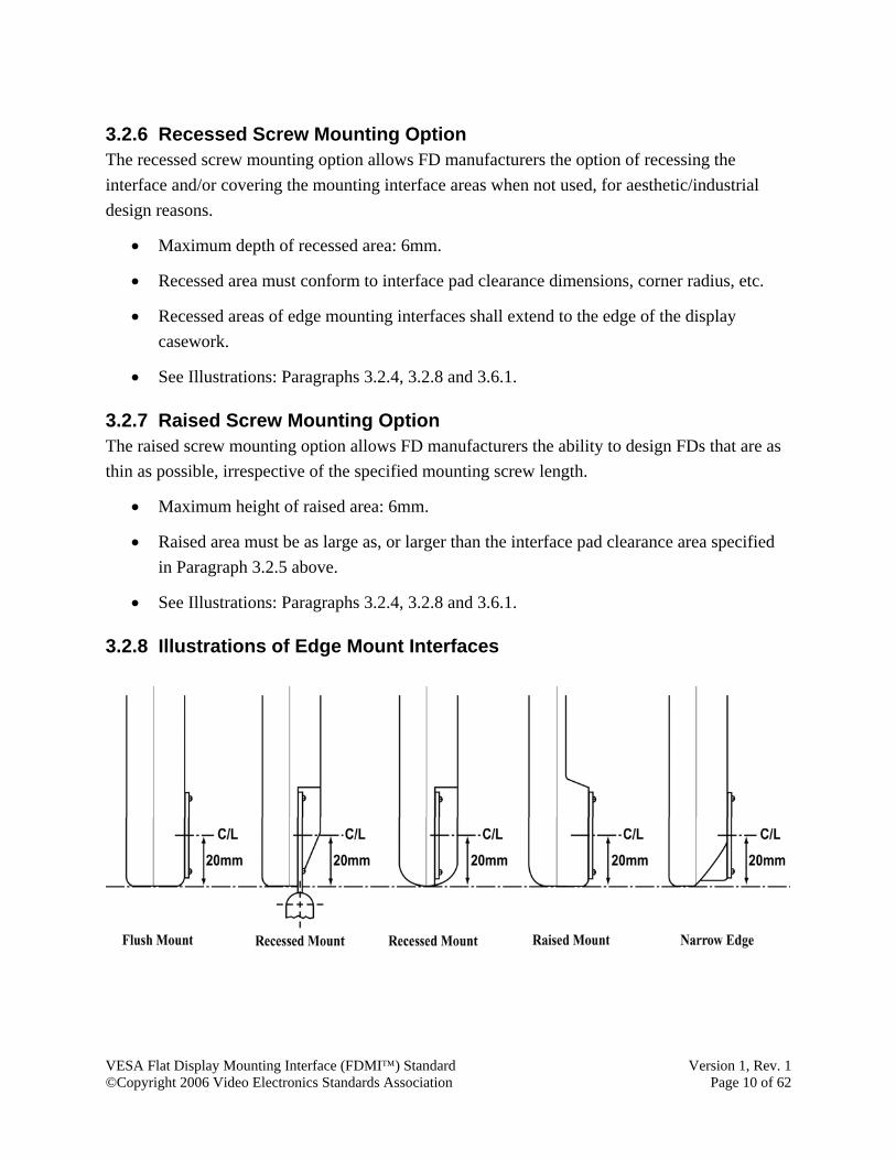
3.2.6 Recessed Screw Mounting Option The recessed screw mounting option allows FD manufacturers the option of recessing the interface and/or covering the mounting interface areas when not used, for aesthetic/industrial design reasons.
• Maximum depth of recessed area: 6mm.
• Recessed area must conform to interface pad clearance dimensions, corner radius, etc.
• Recessed areas of edge mounting interfaces shall extend to the edge of the display casework.
• See Illustrations: Paragraphs 3.2.4, 3.2.8 and 3.6.1.
3.2.7 Raised Screw Mounting Option The raised screw mounting option allows FD manufacturers the ability to design FDs that are as thin as possible, irrespective of the specified mounting screw length.
• Maximum height of raised area: 6mm.
• Raised area must be as large as, or larger than the interface pad clearance area specified in Paragraph 3.2.5 above.
• See Illustrations: Paragraphs 3.2.4, 3.2.8 and 3.6.1.
3.2.8 Illustrations of Edge Mount Interfaces

VESA Flat Display Mounting Interface (FDMI™) Standard Version 1, Rev. 1 ©Copyright 2006 Video Electronics Standards Association Page 11 of 62
3.3 Weight Limit Specifications Displays that exceed the weight limitations for this Part B, Section 3 of FDMI shall utilize the mounting interface specified in Part C, Section 4.
• Such displays shall be labeled as specified in Section 4, Paragraph 4.4.
3.4 Mounting Interface Compliance Identification/Label All FDs complying with this Part B, Section 3 of FDMI shall be labeled as follows:
• VESA MIS-B, (C, B, T, L, R, B/T or L/R) (Example: MIS-B, C).
• If the mounting interface is located a greater distance from the edge of the display than specified in Paragraph 3.2.2, it shall be labeled with the center mount designation (C).
• Right or left designation of an edge located mounting interface shall be as viewed from the rear of the monitor.
• See Section 8 for compliance labeling guidelines.
3.5 Alternate Mounting Interface Options See Section 9.
3.6 Part B - Interface Mounting Pad Specifications • FD mounting device manufacturers shall provide a standardized interface mounting pad
as follows:
Interface Mounting Pad Specifications 50 mm x 20 mm Screw Mounting Pattern
Hole spacing 50 mm x 20 mm (1.968” x .787”) +/- .25 mm (.010”)
Pad size 65 mm x 35 mm (2.559” x 1.378”), 6 mm R (4)
Flat mounting area required 67 mm x 37 mm (2.638” x 1.457”), 0 – 7 mm R (4)
Pad thickness 2 mm or 14 GA (.075"–.080")
Hole size in pad (4 ea.) 5 mm ø (0.197"ø)
Pad material Steel *
Mounting screws (4 ea.) 4 mm ø, .7 pitch x 6 mm long **
* Other suitable materials may be used as long as the pad dimensional specifications outlined herein are adhered to. See Section 11, Good Engineering Practices.
** Unless otherwise specified and supplied by FD manufacturer.

VESA Flat Display Mounting Interface (FDMI™) Standard Version 1, Rev. 1 ©Copyright 2006 Video Electronics Standards Association Page 12 of 62
• Display manufacturers may supply a mounting device, e.g., desk stand, with a mounting interface design of their choice as long as the user can optionally remove the supplied mounting device and mount the display on a mounting device that complies with the interface pad specifications described herein.
3.6.1 Illustration of Part B - Standard Interface Pad Configuration
3.6.2 Interface Pad Profiles The following are illustrations of acceptable interface pad profiles that mounting equipment manufacturers may supply to comply with this standard.

VESA Flat Display Mounting Interface (FDMI™) Standard Version 1, Rev. 1 ©Copyright 2006 Video Electronics Standards Association Page 13 of 62
4 Part C – Mounting Interface Standard for 8” to 11.9” Diagonal Flat Displays
4.1 Application Part C of the standard defines a mounting interface for FDs with a viewing area ranging in size from 203 mm (8”) to 303 mm (11.9”) and weighing up to 4.5 kg (10 lbs.) See Paragraph 1.3.7.
The weight designation referred to in this section of the standard shall include all options for attachment to the FD that are supported by the manufacturer whether the option is shipped with the FD or sold separately. Examples of options include speakers and TV tuner.
4.2 Screw Mounting Interface This standard utilizes a four-hole screw mounting interface pattern integrated into the rear of the FD. The four-hole pattern may be located flush with the rear of the display, may be raised or may be recessed. The FD manufacturer shall be responsible for providing the necessary structural integrity of the mounting interface to accommodate the weight and size of the display, intended applications, etc.
4.2.1 Screw Mounting Interface Dimensions • 75 mm wide by 35 mm high hole pattern
• Hole spacing tolerances: +/- .25 mm (.010”)
• See Illustration: Paragraph 4.2.4
4.2.2 Screw Mounting Hole Pattern Location • The mounting hole pattern(s) shall be located at the rear of the display, centered over the
Horizontal CL to facilitate top, center or bottom mounting, or the hole pattern may be located at the left or right edge of the display, centered over the Vertical CL at the display manufacturer’s option. For specialized applications requiring mount of the display at both top and bottom or at both left and right edges, multiple four-hole edge mounting patterns may be provided.
• For monitors intended for general-purpose applications, placing the mounting interface at the intersection of the display’s Horizontal and Vertical CL is the preferred location. This will provide maximum flexibility for use with the specialty mounting devices, facilitate use of vertically adjustable desk stands and optimize portrait/landscape rotation.
• The CL of mounting interfaces located at the top, bottom, left or right edge of the display shall be located 30 mm +/- .5 mm from the physical edge of the display casework to

VESA Flat Display Mounting Interface (FDMI™) Standard Version 1, Rev. 1 ©Copyright 2006 Video Electronics Standards Association Page 14 of 62
provide adequate clearance and to accommodate the mounting pad dimensions and profiles of this Part C, Section 4.
• See Illustrations: Paragraphs 4.2.4, 4.2.8, 4.6.1 and 4.6.2.
4.2.3 Mounting Screw Specifications • Four (ea.) 4 mm ∅, .7 pitch x 8 mm long screws
• If specified mounting screws are not utilized, the display manufacturer must specify and supply the correct mounting screws.
4.2.4 Illustration of Part C - 75 mm x 35 mm Screw Mounting Interface Pattern
4.2.5 Screw Mounting Interface Clearance Requirements The flush or recessed screw mounting interface options require a flat area on the rear of the display corresponding to the size of the mounting device interface pad as follows: (See Illustration: Paragraph 4.6.1.)
Hole Pattern Interface Pad Size Clearance Area Required
75 mm x 35 mm 90 mm x 50 mm, 6 mm R (4) 92 mm x 52 mm, 0 – 7 mm R (4)

VESA Flat Display Mounting Interface (FDMI™) Standard Version 1, Rev. 1 ©Copyright 2006 Video Electronics Standards Association Page 15 of 62
4.2.6 Recessed Screw Mounting Option The recessed screw mounting option allows FD manufacturers the option of recessing the interface and/or covering the mounting interface area when not used, for aesthetic/industrial design reasons.
• Maximum depth of recessed area: 8 mm.
• Recessed area must conform to interface pad clearance dimensions, corner radius, etc.
• Recessed areas of edge mounting interfaces shall extend to the edge of the display casework.
• See Illustrations: Paragraphs 4.2.4, 4.2.8 and 4.6.1.
4.2.7 Raised Screw Mounting Option The raised screw mounting option allows FD manufacturers the ability to design FDs that are as thin as possible, irrespective of the specified mounting screw length.
• Maximum height of raised area: 8mm.
• Raised area must be as large as, or larger than the interface pad clearance area as specified in Paragraph 4.2.5 above.
• See Illustrations: Paragraphs 4.2.4, 4.2.8 and 4.6.1.
4.2.8 Illustrations of Edge Mount Interfaces

VESA Flat Display Mounting Interface (FDMI™) Standard Version 1, Rev. 1 ©Copyright 2006 Video Electronics Standards Association Page 16 of 62
4.3 Weight Limit Specifications Displays that exceed the weight limitations for this Part C, Section 4 of this standard shall utilize the mounting interface specified in Part D, Section 5.
• Such displays shall be labeled as specified in Section 5, Paragraph 5.4.
4.4 Mounting Interface Compliance Identification/Label All FDs complying with this Part C, Section 4 of FDMI shall be labeled as follows:
• VESA MIS-C, (C, B, T, L, R, B/T or L/R) (Example: MIS-C, T).
• If the mounting interface is located a greater distance from the edge of the display than specified in Paragraph 4.2.2, it shall be labeled with the center mount designation (C).
• Right or left designation of an edge located mounting interface shall be as viewed from the rear of the monitor.
• See Section 8 for compliance labeling guidelines.
4.5 Alternate Mounting Interface Options See Section 9.
4.6 Part C - Interface Mounting Pad Specifications • FD mounting device manufacturers shall provide a standardized interface mounting pad
as follows:
Interface Mounting Pad Specifications 75 mm x 35 mm Screw Mounting Pattern
Hole spacing 75 mm x 35 mm (2.953” x 1.378”) +/- .25 mm (.010”)
Pad size 90 mm x 50 mm (3.543” x 1.968”), 6 mm R (4)
Flat mounting area required 92 mm x 52 mm (3.622” x 2.047”), 0 – 7 mm R (4)
Pad thickness 2.6 mm or 12 GA (.102"–.105")
Hole size in pad (4 ea.) 5 mm ø (0.197"ø)
Pad material Steel *
Mounting screws (4 ea.) 4 mm ø, .7 pitch x 8 mm long **
* Other suitable materials may be used as long as the Pad dimensional specifications outlined herein are adhered to. See Section 11, Good Engineering Practices.
** Unless otherwise specified and supplied by FD manufacturer.

VESA Flat Display Mounting Interface (FDMI™) Standard Version 1, Rev. 1 ©Copyright 2006 Video Electronics Standards Association Page 17 of 62
• Display manufacturers may supply a mounting device, e.g., desk stand, with a mounting interface design of their choice as long as the user can optionally remove the supplied mounting device and mount the display on a mounting device that complies with the interface pad specifications described herein.
4.6.1 Illustration of Part C - Standard Interface Pad Configuration
4.6.2 Interface Pad Profiles The following are illustrations of acceptable interface pad profiles that mounting equipment manufacturers may supply to comply with this standard.

VESA Flat Display Mounting Interface (FDMI™) Standard Version 1, Rev. 1 ©Copyright 2006 Video Electronics Standards Association Page 18 of 62
5 Part D – Mounting Interface Standard for 12” to 22.9” Diagonal Flat Displays (Replaces FPMPMI™ Standard)
5.1 Application Part D of FDMI defines mounting interfaces for FDs with a viewing area ranging in size from 305 mm (12”) to 583 mm (22.9”) and weighing up to 14 kg (30.8 lbs.). See Paragraph 1.3.7.
The weight designation referred to in this section of the standard shall include all options for attachment to the FD that are supported by the manufacturer whether the option is shipped with the FD or sold separately. Examples of options include speakers and TV tuner.
Part D replaces and supercedes the VESA FPMPMI™ Standard Version 2.0, Revision 3, dated March 1, 1999.
5.2 Part D – Center Located Screw Mounting Interface This standard utilizes a four-hole screw mounting interface pattern integrated into the rear of the FD. The four-hole pattern may be located flush with the rear of the display, may be raised or may be recessed. The FD manufacturer shall be responsible for providing the necessary structural integrity of the mounting interface to accommodate the weight and size of the display, intended applications, etc.
5.2.1 Screw Mounting Interface Dimensions • Preferred, center-located mounting interface implementation
o Use 100 mm x 100 mm hole spacing for all displays weighing up to 14 kg (30.8 lbs.)
o See Illustration: Paragraph 5.2.4.1.
• Alternate, center located mounting interface implementation for smaller displays
o 75 mm x 75 mm hole spacing may be used for smaller displays, typically weighing less than 8 kg (17.6 lbs.)
o See Illustration: Paragraph 5.2.4.2.
• All hole spacing tolerances: +/- .25 mm (.010”)
5.2.2 Screw Mounting Hole Pattern Location • In all cases the screw mounting hole pattern should be placed at the display Horizontal
CL and at the Vertical CL. Placing the mounting hole pattern at the vertical CL is extremely important if the FD manufacturer desires to provide optimum performance and user adjustability when the display is mounted on arms or pivot systems that offer a full

VESA Flat Display Mounting Interface (FDMI™) Standard Version 1, Rev. 1 ©Copyright 2006 Video Electronics Standards Association Page 19 of 62
range of adjustment, i.e., up to 180º, or on desk stands offering vertical adjustability and/or 90º of rotation for portrait/landscape applications.
• See Illustrations: Paragraph 5.2.4.
5.2.3 Mounting Screw Specifications • Four (ea.) 4 mm ∅, .7 pitch x 10 mm long screws
• If specified mounting screws are not utilized, the display manufacturer must specify and supply the correct mounting screws.
5.2.4 Illustrations of Part D Center Located Screw Mounting Interface Patterns
5.2.4.1 Illustration of Preferred 100 mm x 100 mm Screw Mounting Pattern
* Change from FPMPMI™ Standard

VESA Flat Display Mounting Interface (FDMI™) Standard Version 1, Rev. 1 ©Copyright 2006 Video Electronics Standards Association Page 20 of 62
5.2.4.2 Illustration of Alternate 75 mm x 75 mm Screw Mounting Pattern
* Change from FPMPMI™ Standard
5.2.5 Screw Mounting Interface Clearance Requirements The flush or recessed screw mounting options require a flat area on the rear of the display corresponding to the size of the mounting device interface pad as follows: (See Illustrations: Paragraph 5.6.1).
Hole Pattern Interface Pad Size Clearance Area Required
100 mm x100 mm 115 mm x 115 mm, 6 mm R (4) 117 mm x 117 mm, 0 – 7 mm R (4)
75 mm x 75 mm 90 mm x 90 mm, 6 mm R (4) 92 mm x 92 mm, 0 – 7 mm R (4)
5.2.6 Recessed Screw Mounting Option The recessed screw mounting option allows FD manufacturers the option of recessing the interface and/or covering the mounting interface area when not used, for aesthetic/industrial design reasons.
• Maximum depth of recessed area: 10 mm.
• Recessed area must conform to interface pad clearance dimensions, corner radius, etc.
• See Illustrations: Paragraphs 5.2.4 and 5.6.1.

VESA Flat Display Mounting Interface (FDMI™) Standard Version 1, Rev. 1 ©Copyright 2006 Video Electronics Standards Association Page 21 of 62
5.2.7 Raised Screw Mounting Option The raised screw mounting option allows FD manufacturers the ability to design FDs that are as thin as possible, irrespective of the specified mounting screw length.
• Maximum height of raised area: 10 mm.
• Raised area must be as large as or larger than the interface pad clearance area as specified in Paragraph 5.2.5 above.
• See Illustrations: Paragraphs 5.2.4 and 5.6.1.
5.3 Weight Limit Specifications • Monitors that exceed the weight limitations for this Part D, Section 5 of this standard
shall utilize the mounting interface specified for Part E, Section 6 of this standard.
• Such monitors shall be labeled as specified in Section 6, Paragraph 6.4.
5.4 Center Located Mounting Interface Compliance Identification/ Label
All FDs complying with the center located interface only of this Part D, Section 5 of FDMI shall be labeled as follows:
• VESA MIS-D, 100, C, or;
• VESA MIS-D, 75, C.
• See Section 8 for compliance labeling guidelines.
5.5 Alternate Mounting Interface Options See Section 9.

VESA Flat Display Mounting Interface (FDMI™) Standard Version 1, Rev. 1 ©Copyright 2006 Video Electronics Standards Association Page 22 of 62
5.6 Part D – Center Located Interface Mounting Pad Specifications • FD mounting device manufacturers shall provide a standardized interface mounting pad
as follows:
Interface Mounting Pad Specifications
100 mm x 100 mm Screw Mounting Pattern
75 mm x 75 mm Screw Mounting Pattern
Hole spacing 100 mm x 100 mm (3.937”) 75 mm x 75 mm (2.953”)
Hole spacing tolerances +/- .25 mm (.010”) +/- .25 mm (.010”)
Pad size 115 mm x 115 mm (4.527”), 6 mm R (4)
90 mm x 90 mm (3.543”), 6 mm R (4)
Flat mounting area required 117 mm x 117 mm (4.606”), 0 – 7 mm R (4)
92 mm x 92 mm (3.622”), 0 – 7 mm R (4)
Pad thickness 2.6 mm or 12 GA (0.102”-0.105”) 2.6 mm or 12 GA (0.102”-0.105”)
Hole size in pad (4 ea.) 5 mm ø (0.197"ø) 5 mm ø (0.197"ø)
Pad material Steel * Steel *
Mounting screws (4 ea.) 4 mm ø, .7 pitch x 10 mm long ** 4 mm ø, .7 pitch x 10 mm long **
* Other suitable materials may be used as long as the pad dimensional specifications outlined herein are adhered to. See Section 11, Good Engineering Practices.
** Unless otherwise specified and supplied by FD manufacturer.
• Display manufacturers may supply a mounting device, e.g., desk stand, with a mounting interface design of his choice as long as the user can optionally remove the supplied mounting device and mount the display on a mounting device that complies with the interface pad specifications described herein.

VESA Flat Display Mounting Interface (FDMI™) Standard Version 1, Rev. 1 ©Copyright 2006 Video Electronics Standards Association Page 23 of 62
5.6.1 Illustration of Part D - Standard Interface Pad Configurations
5.6.2 Interface Pad Profiles The following are illustrations of acceptable interface pad profiles that mounting equipment manufacturers may supply to comply with this standard.
* Change from FPMPMI. This interface pad profile is now acceptable.
*

VESA Flat Display Mounting Interface (FDMI™) Standard Version 1, Rev. 1 ©Copyright 2006 Video Electronics Standards Association Page 24 of 62
5.7 Part D – Edge Located Screw Mounting Interfaces * To facilitate fixed desk stand, overhead or left or right edge mounting applications, FD manufacturers may provide edge located four-hole mounting pattern(s) integrated into the rear of the display. The edge located four-hole pattern(s) may be located flush with the rear of the display, may be raised or may be recessed. The FD manufacturer shall be responsible for providing the necessary structural integrity of the mounting interface to accommodate the weight and size of the monitor, intended applications, etc.
5.7.1 Edge Located Screw Mounting Hole Pattern Selection • Use 100 mm wide by 50 mm high hole spacing in conjunction with 100 mm x 100 mm
center located interface specified in Paragraph 5.2.1 of this Part D, Section 5.
• Use 75 mm wide by 50 mm high hole spacing in conjunction with 75 mm x 75 mm center located interface specified in Paragraph 5.2.1 of this Part D, Section 5.
• If center located interface is not provided, select edge located mounting hole pattern width according to the guidelines set forth in Paragraph 5.2.1 above.
5.7.2 Edge Located Screw Mounting Hole Pattern Location • The mounting hole pattern(s) shall be located at the rear of the display, centered over the
Horizontal CL to facilitate top or bottom mounting, or the hole pattern(s) may be located at the left or right edge of the display, centered over the Vertical CL at the display manufacturer’s option. For specialized applications requiring mount of the display at both top and bottom or at both left and right edges, multiple four-hole edge mounting patterns may be provided.
• The CL of mounting interfaces located at the top, bottom, left or right edge of the display shall be located 35 mm +/- .5 mm from the physical edge of the display casework to provide adequate clearance and to accommodate the mounting pad dimensions and profiles of this Part D, Section 5.
• See Illustrations: Paragraphs 5.7.4, 5.7.8, 5.11.1 and 5.11.2.
5.7.3 Mounting Screw Specifications • Four (ea.) 4 mm ∅, .7 pitch x 10 mm long screws
• If specified mounting screws are not utilized, the display manufacturer must specify and supply the correct mounting screws.
* Replaces Section 4 of FPMPMI.

VESA Flat Display Mounting Interface (FDMI™) Standard Version 1, Rev. 1 ©Copyright 2006 Video Electronics Standards Association Page 25 of 62
5.7.4 Illustrations of Part D – Edge Located Desk Stand, Overhead or Left or Right Mount Screw Mounting Interface Patterns
5.7.5 Edge Located Screw Mounting Interface Clearance Requirements The flush or recessed screw mounting options require a flat area on the rear of the display corresponding to the size of the mounting device interface pad as follows: (See Illustrations: Paragraph 5.11.1.)
Hole Pattern Interface Pad Size Clearance Area Required
100 mm x50mm 115 mm x 65 mm, 6 mm R (4) 117 mm x 67 mm, 0 – 7 mm R (4)
75 mm x 50mm 90 mm x 65 mm, 6 mm R (4) 92 mm x 67 mm, 0 – 7 mm R (4)
5.7.6 Recessed Screw Mounting Option The recessed screw mounting option allows FD manufacturers the option of recessing the interface and/or covering the mounting interface area when not used, for aesthetic/industrial design reasons.
• Maximum depth of recessed area: 10 mm.
• Recessed area must conform to interface pad clearance dimensions, corner radius, etc.
• Recessed areas of edge mounting interfaces shall extend to the edge of the display casework.
• See Illustrations: Paragraphs 5.2.4, 5.7.8 and 5.11.1.

VESA Flat Display Mounting Interface (FDMI™) Standard Version 1, Rev. 1 ©Copyright 2006 Video Electronics Standards Association Page 26 of 62
5.7.7 Raised Screw Mounting Option The raised screw mounting option allows FD manufacturers the ability to design FDs that are as thin as possible, irrespective of the specified mounting screw length.
• Maximum height of raised area: 10 mm.
• Raised area must be as large as, or larger than the interface pad clearance area as specified in Paragraph 5.7.5 above.
• See Illustrations: Paragraphs 5.2.4, 5.7.8 and 5.11.1.
5.7.8 Illustrations of Edge Mount Interfaces
5.8 Weight Limit Specifications Displays that exceed the weight limitations for this Part D, Section 5 of this standard shall utilize the mounting interface specified for Part E, Section 6.
• Such monitors shall be labeled as specified in Section 6, Paragraph 6.4.
5.9 Mounting Interface Compliance Identification/Label All FDs complying with Part D, Section 5, Paragraphs 5.6 and/or 5.7 of FDMI shall be labeled as follows:
• VESA MIS-D, (100 or 75), C or
• VESA MIS-D, (100 or 75), (B, T, L, R, B/T or L/R) or
• VESA MIS-D, (100 or 75), (C, B, T, L, R, B/T or L/R).

VESA Flat Display Mounting Interface (FDMI™) Standard Version 1, Rev. 1 ©Copyright 2006 Video Electronics Standards Association Page 27 of 62
• Right or left designation of an edge located mounting interface shall be as viewed from the rear of the monitor.
• See Section 8 for compliance labeling guidelines.
5.10 Alternate Mounting Interface Options See Section 9.
5.11 Part D – Edge Located Interface Mounting Pad Specifications FD mounting device manufacturers shall provide a standardized interface mounting pad as follows:
Interface Mounting Pad Specifications
100 mm x 50 mm Screw Mounting Pattern
75 mm x 50 mm Screw Mounting Pattern
Hole spacing 100 mm x 50 mm (3.937” x 1.968”)
75 mm x 50 mm (2.953” x 1.968”)
Hole spacing tolerances +/- .25 mm (.010”) +/- .25 mm (.010”)
Pad size 115 mm x 65 mm (4.527” x 2.559”), 6 mm R (4)
90 mm x 65 mm (3.543” x 2.559”), 6 mm R (4)
Flat mounting area required 117 mm x 67 mm (4.606” x 2.638”), 0 – 7 mm R (4)
92 mm x 67 mm (3.622” x 2.638”), 0 – 7 mm R (4)
Pad thickness 2.6 mm or 12 GA (0.102”-0.105”) 2.6 mm or 12 GA (0.102”-0.105”)
Hole size in pad (4 ea.) 5 mm ø (0.197"ø) 5 mm ø (0.197"ø)
Pad material Steel * Steel *
Mounting screws (4 ea.) 4 mm ø, .7 pitch x 10 mm long * 4 mm ø, .7 pitch x 10 mm long **
* Other suitable materials may be used as long as the pad dimensional specifications outlined herein are adhered to. See Section 11, Good Engineering Practices.
** Unless otherwise specified and supplied by FD manufacturer.
• Display manufacturers may supply a mounting device, e.g., desk stand, with a mounting interface design of his choice as long as the user can optionally remove the supplied mounting device and mount the display on a mounting device that complies with the interface pad specifications described herein.

VESA Flat Display Mounting Interface (FDMI™) Standard Version 1, Rev. 1 ©Copyright 2006 Video Electronics Standards Association Page 28 of 62
5.11.1 Illustration of Part D – Edge Located Interface Pad Configurations
5.11.2 Interface Pad Profiles The following are illustrations of acceptable interface pad profiles that mounting equipment manufacturers may supply to comply with FDMI.

VESA Flat Display Mounting Interface (FDMI™) Standard Version 1, Rev. 1 ©Copyright 2006 Video Electronics Standards Association Page 29 of 62
6 Part E – Mounting Interface Standard for 23” to 30.9” Diagonal Flat Displays
6.1 Application Part E of FDMI defines mounting interfaces for FDs with a viewing area ranging in size from 584 mm (23”) to 786 mm (30.9”) and weighing up to 22.7 kg (50 lbs.). See Paragraph 1.3.7.
The weight designation referred to in this section of the standard shall include all options for attachment to the FD that are supported by the manufacturer whether the option is shipped with the FD or sold separately. Examples of options include speakers and TV tuner.
6.2 Part E – Center Located Screw Mounting Interface This standard utilizes a six-hole screw mounting interface pattern integrated into the rear of the FD. The six-hole pattern may be located flush with the rear of the display, may be raised or may be recessed. The FD manufacturer shall be responsible for providing the necessary structural integrity of the mounting interface to accommodate the weight and size of the monitor, intended applications, etc.
6.2.1 Screw Mounting Interface Dimensions • 200 mm wide by 100 mm high hole pattern, +/- .25 mm (.010”)
• See Illustration: Paragraph 6.2.4.
6.2.2 Screw Mounting Hole Pattern Location • In all cases the screw mounting hole pattern should be placed at the display Horizontal
CL and at the Vertical CL. Placing the mounting hole pattern at the Vertical CL is extremely important if the FD manufacturer desires to provide optimum performance and user adjustability when the display is mounted on arms or pivot systems that offer a full range of adjustment, i.e., up to 180º, or on desk stands offering vertical adjustability and/or 90º of rotation for portrait/landscape applications.
• See Illustration: Paragraph 6.2.4.
6.2.3 Mounting Screw Specifications • Six (ea.) 4 mm ∅, .7 pitch x 10 mm long screws
• If specified mounting screws are not utilized, the display manufacturer must specify and supply the correct mounting screws.

VESA Flat Display Mounting Interface (FDMI™) Standard Version 1, Rev. 1 ©Copyright 2006 Video Electronics Standards Association Page 30 of 62
6.2.4 Illustration of Part E – Center Located 200 mm x 100 mm Screw Mounting Interface Pattern
6.2.5 Screw Mounting Interface Clearance Requirements The flush or recessed screw mounting options require a flat area on the rear of the display corresponding to the size of the mounting device interface pad as follows: (See Illustration: Paragraph 6.6.1.)
Hole Pattern Interface Pad Size Clearance Area Required
200 mm x 100mm 215 mm x 115 mm, 6 mm R (4) 217 mm x 117 mm, 0 – 7 mm R (4)
6.2.6 Recessed Screw Mounting Option The recessed screw mounting option allows FD manufacturers the option of recessing the interface and/or covering the mounting interface area when not used, for aesthetic/industrial design reasons.
• Maximum depth of recessed area: 10 mm.
• Recessed area must conform to Interface pad clearance dimensions, corner radius, etc.
• See Illustrations: Paragraphs 6.2.4 and 6.6.1.

VESA Flat Display Mounting Interface (FDMI™) Standard Version 1, Rev. 1 ©Copyright 2006 Video Electronics Standards Association Page 31 of 62
6.2.7 Raised Screw Mounting Option The raised screw mounting option allows FD manufacturers the ability to design FDs that are as thin as possible, irrespective of the specified mounting screw length.
• Maximum height of raised area: 10 mm.
• Raised area must be as large as or larger than the interface pad clearance area as specified in Paragraph 6.2.5 above.
• See Illustrations: Paragraphs 6.2.4 and 6.6.1.
6.3 Weight Limit Specifications • Displays that exceed the weight limitations for Part E of this standard shall utilize the
mounting interface specified for Part F, Section 7 of this standard.
• Such displays shall be labeled as specified in Section 8.
6.4 Mounting Interface Compliance Identification/Label All FDs complying with the center located interface only of this Part E, Section 6 of the FDMI shall be labeled as follows:
• VESA MIS-E, C
• See Section 8 for compliance labeling guidelines.
6.5 Alternate Physical Mounting Interface Options See Section 9.

VESA Flat Display Mounting Interface (FDMI™) Standard Version 1, Rev. 1 ©Copyright 2006 Video Electronics Standards Association Page 32 of 62
6.6 Part E – Center Located Interface Mounting Pad Specifications • FD mounting device manufacturers shall provide a standardized interface mounting pad
as follows:
Interface Mounting Pad Specifications 200 mm x 100 mm Screw Mounting Pattern
Hole spacing 200 mm x 100 mm (7.874” x 3.937”)
Hole spacing tolerance +/- .25 mm (.010”)
Pad size 215 mm x 115 mm (8.464” x 4.527”), 6 mm R (4)
Flat mounting area required 217 mm x 117 mm (8.543” x 4.606”), 0 – 7 mm R (4)
Pad thickness 2.6 mm or 12 GA (0.102”-0.105”)
Hole size in pad (6 ea.) 5 mm ø (0.197"ø)
Pad material Steel*
Mounting screws (6 ea.) 4 mm ø, .7 pitch x 10 mm long**
* Other suitable materials may be used as long as the pad dimensional specifications outlined herein are adhered to. See Section 11, Good Engineering Practices.
** Unless otherwise specified and supplied by FD manufacturer.
• Display manufacturers may supply a mounting device, e.g., desk stand, with a mounting interface design of his choice as long as the user can optionally remove the supplied mounting device and mount the display on a mounting device that complies with the interface pad specifications described herein.

VESA Flat Display Mounting Interface (FDMI™) Standard Version 1, Rev. 1 ©Copyright 2006 Video Electronics Standards Association Page 33 of 62
6.6.1 Illustration of Part E – Center Located Interface Pad Configuration
6.6.2 Interface Pad Profiles The following are illustrations of acceptable interface pad profiles that mounting equipment manufacturers may supply to comply with this standard.

VESA Flat Display Mounting Interface (FDMI™) Standard Version 1, Rev. 1 ©Copyright 2006 Video Electronics Standards Association Page 34 of 62
6.7 Part E – Edge Located Screw Mounting Interface To facilitate fixed desk stand, overhead, left or right mounting applications, FD manufacturers may provide edge located six-hole mounting pattern(s) integrated into the rear of the display. The six-hole pattern(s) may be located flush with the rear of the display, may be raised or may be recessed. The FD manufacturer shall be responsible for providing the necessary structural integrity of the mounting interface to accommodate the weight and size of the monitor, intended applications, etc.
6.7.1 Screw Mounting Interface Dimensions • 200 mm wide by 50 mm high hole pattern, +/- .25 mm (.010”)
• See Illustration: Paragraph 6.7.4.
6.7.2 Screw Mounting Hole Pattern Location • The mounting hole pattern(s) shall be located at the rear of the display, centered over the
Horizontal CL to facilitate top or bottom mounting, or the hole pattern may be located at the left or right edge of the display, centered over the Vertical CL at the display manufacturer’s option. For specialized applications requiring mount of the display at both top and bottom or at both left and right edges, multiple four-hole edge mounting patterns may be provided.
• The CL of mounting interfaces located at the top, bottom, left or right edge of the display shall be located 35 mm +/- .5 mm from the physical edge of the display casework to provide adequate clearance and to accommodate the mounting pad dimensions and profiles of this Part E, Section 6.
• See Illustration: Paragraphs 6.7.4, 6.7.8, 6.11.1 and 6.11.2.
6.7.3 Mounting Screw Specifications • Six (ea.) 4 mm ∅, .7 pitch x 10 mm long screws
• If specified mounting screws are not utilized, the display manufacturer must specify and supply the correct mounting screws.

VESA Flat Display Mounting Interface (FDMI™) Standard Version 1, Rev. 1 ©Copyright 2006 Video Electronics Standards Association Page 35 of 62
6.7.4 Illustrations of Part E – Edge Mounted Desk Stand, Overhead, Left or Right Mount Screw Mounting Interface Patterns
6.7.5 Screw Mounting Interface Clearance Requirements The flush or recessed screw mounting options require a flat area on the rear of the display corresponding to the size of the mounting device interface pad as follows:
Hole Pattern Interface Pad Size Clearance Area Required
200 mm x 50mm 215 mm x 65 mm, 6 mm R (4) 217 mm x 67 mm, 0 – 7 mm R (4)
• See Illustration: Paragraph 6.11.1.
6.7.6 Recessed Screw Mounting Option The recessed screw mounting option allows FD manufacturers the option of recessing the interface and/or covering the mounting interface area when not used, for aesthetic/industrial design reasons.
• Maximum depth of recessed area: 10mm
• Recessed area must conform to Interface pad clearance dimensions, corner radius, etc.

VESA Flat Display Mounting Interface (FDMI™) Standard Version 1, Rev. 1 ©Copyright 2006 Video Electronics Standards Association Page 36 of 62
• Recessed areas of edge mounting interfaces shall extend to the edge of the display casework.
• See Illustrations: Paragraphs 6.2.4, 6.7.8 and 6.11.1.
6.7.7 Raised Screw Mounting Option The raised screw mounting option allows FD manufacturers the ability to design FDs that are as thin as possible, irrespective of the specified mounting screw length.
• Maximum height of raised area: 10 mm.
• Raised area must be as large as or larger than the interface pad clearance area as specified in Paragraph 6.7.5 above.
• See Illustrations: Paragraphs 6.7.4, 6.7.8 and 6.11.1.
6.7.8 Illustrations of Edge Mount Interfaces
6.8 Weight Limit Specifications • Monitors that exceed the weight limitations for this Part E, Section 6 of this standard
shall utilize the mounting interface specified for Part F, Section 7 of this standard.
• Such monitors shall be labeled as specified in Section 8.

VESA Flat Display Mounting Interface (FDMI™) Standard Version 1, Rev. 1 ©Copyright 2006 Video Electronics Standards Association Page 37 of 62
6.9 Mounting Interface Compliance Identification/Label All FDs complying with this Part D, Section 6, Paragraphs 6.6 and/or 6.7 of FDMI shall be labeled as follows:
• VESA MIS-E, C or
• VESA MIS-E, (B, T, L, R, B/T or L/R) or
• VESA MIS-E, (C, B, T, L, R, B/T or L/R).
• Right or left designation of an edge located mounting interface shall be as viewed from the rear of the monitor.
• See Section 8 for compliance labeling guidelines.
6.10 Alternate Mounting Interface Options See Section 9.
6.11 Part E – Edge Located Interface Mounting Pad Specifications • FD mounting device manufacturers shall provide a standardized edge mount interface
mounting pad as follows:
Interface Mounting Pad Specifications 200 mm x 50 mm Screw Mounting Pattern
Hole spacing 200 mm x 50 mm (7.874” x 1.968”)
Hole spacing tolerance +/- .25 mm (.010”)
Pad size 215 mm x 65 mm (8.464” x 2.559”), 6 mm R (4)
Flat mounting area required 217 mm x 67 mm (8.543” x 2.638”), 0 – 7 mm R (4)
Pad thickness 2.6 mm or 12 GA (0.102”-0.105”)
Hole size in pad (6 ea.) 5 mm ø (0.197"ø)
Pad material Steel*
Mounting screws (6 ea.) 4 mm ø, .7 pitch x 10 mm long**
* Other suitable materials may be used as long as the pad dimensional specifications outlined herein are adhered to. See Section 11, Good Engineering Practices.
** Unless otherwise specified and supplied by FD manufacturer.
• Display manufacturers may supply a mounting device, e.g., desk stand, with a mounting interface design of his choice as long as the user can optionally remove the supplied mounting device and mount the display on a mounting device that complies with the interface pad specifications described herein.

VESA Flat Display Mounting Interface (FDMI™) Standard Version 1, Rev. 1 ©Copyright 2006 Video Electronics Standards Association Page 38 of 62
6.11.1 Illustration of Part E – Edge Located Interface Pad Configuration
6.11.2 Interface Pad Profiles The following are illustrations of acceptable interface pad profiles that mounting equipment manufacturers may supply to comply with this standard.

VESA Flat Display Mounting Interface (FDMI™) Standard Version 1, Rev. 1 ©Copyright 2006 Video Electronics Standards Association Page 39 of 62
7 Part F – Mounting Interface Standard for 31” and Larger Diagonal Flat Displays
7.1 Application Part F of the standard defines a mounting interface for FDs with a viewing area ranging in size from 785 mm (31”) and larger.
The mounting interface defined by Part F, Section 7 of FDMI shall focus primarily on wall mount applications, although the standard shall be applicable to stand, cart, pole, arm and other specialty mounting options as well.
7.2 Objectives This standard is designed to provide the following objectives. The standard shall:
• Provide a flexible mounting interface that can be adapted to a broad range of FD sizes ranging from 785 mm (31”) and larger.
• Be optimized for wall mount applications. However, it must also be easily interfaced to appropriate specialized mounting apparatus for cart, stand, pole and other specialty mounting applications.
• Allow complete mounting flexibility of the display in any attitude, including mount to angled walls, overhead ceiling mounts or to specialized mounting apparatus, which provide a full range of adjustment motion.
• Allow mounting of displays to walls or specialty mounting apparatus with low cost mounting hardware utilizing commonly available hand tools and industry standard mounting hardware.
• Allow displays to be mounted on the wall in either portrait or landscape orientation and to be securely mounted to specialty mounting apparatus that provide either fixed or rotating portrait/landscape orientation.
• In all cases the end user and/or the installing contractor shall be responsible for providing approved structural walls meeting local building codes, or other mounting apparatus designed to accommodate the weight, mounting attitude and intended application of the flat display.
Note: If portrait-mounting orientation is not applicable to a specific display design, all comments or specifications herein regarding portrait mounting orientation may be ignored.

VESA Flat Display Mounting Interface (FDMI™) Standard Version 1, Rev. 1 ©Copyright 2006 Video Electronics Standards Association Page 40 of 62
7.3 Stand or Mount included with FD by Manufacturer Any stand or mount apparatus that is included with the display by the manufacturer and is attached to the display, must be easily removable by the end user, using standard hand tools, in order to be compliant with this standard.
7.4 Screw Mounting Interface This standard utilizes a multiple-hole screw mounting interface hole pattern consisting of 6 mm ∅, 1.0 pitch x 12 mm or 8 mm ∅, 1.25 pitch x 16 mm minimum depth threaded holes integrated into the rear of the display.
• The multiple-hole pattern may be located flush with the rear-most surfaces of the display or may be raised. The height of the raised interface surface(s) shall be as determined by the FD manufacturer.
• The FD manufacturer shall be responsible for providing the necessary structural integrity of the mounting interface to accommodate the weight and size of the display in all legal mounting attitudes, for intended applications, etc.
• To facilitate mounting of the display in either the landscape or portrait orientation, in all cases the horizontal mounting rows and vertical mounting columns shall be symmetrical.
• The horizontal mounting rows and the vertical mounting columns shall be of equal length and shall utilize the same number of threaded mounting holes, forming a symmetrical pattern.
• The horizontal mounting rows and the vertical mounting columns shall be structural and shall allow the display to be mounted in either the landscape or portrait orientation utilizing either the two horizontal rows or the two vertical columns.
• If the portrait mounting orientation is not a legal mounting orientation for the display, the display manufacturer shall so indicate on the product identification label. See paragraph 8.2 of the standard.
• In this standard all references to row orientation shall be based on the assumption that the display is mounted in the normal landscape orientation.
• In all mounting applications and mounting attitudes, either the two horizontal rows or the two vertical columns of mounting screw inserts shall be utilized to mount the display. See Illustrations in paragraphs 7.6.1, 7.6.2.1 and 7.6.2.2 of the Standard for examples.
• In each of the cases outlined above, it is a requirement that the display mounting apparatus manufacturer fill all the mounting holes in the two vertical columns or the two

VESA Flat Display Mounting Interface (FDMI™) Standard Version 1, Rev. 1 ©Copyright 2006 Video Electronics Standards Association Page 41 of 62
horizontal rows which are used to mount the display, with the appropriate length mounting bolts.
7.4.1 Screw Mounting Interface Dimensions • The size of the screw mounting surface area and the number of mounting holes in each
row shall be determined by the FD manufacturer to meet display size and weight specifications.
• All hole pattern spacing dimensions, both horizontal and vertical, shall be symmetrical and shall be in increments of 100 mm, i.e., 200 mm, 300 mm, 400 mm, 500 mm, 600 mm, 700 mm, 800 mm, 900 mm, 1000 mm, etc., centered over the CL of the display. The hole pattern can not be less than 200 mm.
• The screw mounting interface area shall be flat within 1 mm +/- over the entire mounting interface surface and shall be a minimum of 35 mm larger in all dimensions than the chosen symmetrical hole pattern.
• The mounting hole pattern shall be the maximum protrusion area on the rear of the display.
• Hole spacing tolerances for each hole pattern: +/- .5 mm (.020”) non-accumulative.
• See Illustrations: Paragraphs 7.4.4, 7.4.7 and 7.4.8 of the Standard.
7.4.2 Screw Mounting Hole Pattern Surface Specifications • The mounting hole pattern shall be located at the rear of the display.
• The surface of the screw mounting bolt holes must be flush with the rear surface, or raised surface(s) of the display (+/- .5mm). The bolt holes must provide a firm seating surface adjacent to the hole, a minimum of 4 mm larger in diameter than the diameter of the mounting hole.
• See Illustrations: Paragraphs 7.4.4, and 7.4.9 through 7.4.12.
7.4.3 Mounting Screw Specifications • Wall mount or specialty mounting applications for all displays weighing up to 50 kg (110
lbs.) utilizing standard Hex, Round, Shoulder or Button Head metric bolts
o 6 mm ∅, 1.0 pitch metric bolts. The length will be determined by the display mount manufacturer to allow for a minimum of 1-1/2 times the screw diameter engagement in the threaded insert on the display.
o Quantity to be specified by FD manufacturer.

VESA Flat Display Mounting Interface (FDMI™) Standard Version 1, Rev. 1 ©Copyright 2006 Video Electronics Standards Association Page 42 of 62
o Length to be determined by mounting apparatus manufacturer as follows:
Maximum bolt length equals maximum 10 mm deep screw hole in display, plus thickness of wall mount bracket or specialty mounting apparatus.
See Illustrations: Paragraphs 7.4.9 and 7.4.10.
• Wall mount or specialty mounting applications for all displays weighing over 50 kg (110 lbs.) utilizing standard Hex, Round, Shoulder or Button Head metric bolts
o 8 mm ∅, 1.25 pitch metric bolts. The length will be determined by the display mount manufacturer to allow for a minimum of 1-1/2 times the screw diameter engagement in the threaded insert on the display.
o Quantity to be specified by FD manufacturer.
o Length to be determined by mounting apparatus manufacturer as follows:
Maximum bolt length equals maximum 15 mm deep screw hole in display, plus thickness of wall mount bracket or specialty mounting apparatus.
See Illustrations: Paragraphs 7.4.11 and 7.4.12.
7.4.4 Illustration of Part F – Multiple Screw Mounting Interface Patterns

VESA Flat Display Mounting Interface (FDMI™) Standard Version 1, Rev. 1 ©Copyright 2006 Video Electronics Standards Association Page 43 of 62
Application Notes:
1. Any symmetrical hole pattern in increments of 100 mm (i.e., 200, 300, 400, 500, 600, 800, 1000, etc.) centered over the Horizontal and Vertical CL. The hole pattern can not be less than 200 mm.
2. A hole pattern is a pair of holes dimensioned in 100 mm increments, centered over the CL of the display. For larger displays, FD manufacturer may provide additional holes within a row or column (in 100 mm increments, forming a symmetrical pattern) to support the weight of the display. The number of holes in the upper and lower rows and in the two vertical columns must be the same. The distance between holes must be in 100 mm increments.
3. Hole patterns must be a minimum of 50 mm from the edge of the display so the mounting bracket is not visible when the display is mounted in either landscape or portrait mode. To meet cooling/ventilation objectives, FD manufacturers may increase the minimum 50 mm edge spacing or raise the mounting interface(s) from the surface of the display.
4. Hole spacing tolerances: +/- .5 mm (.020”), non-accumulative.
5. The FD manufacturer is responsible for the structural integrity of the display and for providing the hole spacing and number of mounting holes necessary to comply with all provisions of this standard.
7.4.5 Multiple Screw Mounting Interface Pattern Size Range The multiple screw hole mounting interface allows the specification of a minimum screw hole pattern of 200 mm (7.9”) x 200 mm (7.9”) for smaller displays to hole patterns of up to 1000 mm (39.4”) x 1000 mm (39.4”) or greater, for the largest displays covered by the Standard.
• See Illustration: Paragraph 7.4.8.
7.4.6 Maximum Size Symmetrical Hole Pattern Calculation To determine the maximum size symmetrical hole pattern for a given display, follow the procedure outlined below:
Note: All references to row orientation are based on the assumption that the display is mounted in the normal landscape orientation.
Step 1 Determine height of display cabinet.
Step 2 From cabinet height, subtract 100 mm (2 x 50mm), which is the minimum edge clearance required to insure that the mounting bracket or apparatus does not protrude

VESA Flat Display Mounting Interface (FDMI™) Standard Version 1, Rev. 1 ©Copyright 2006 Video Electronics Standards Association Page 44 of 62
from the edge of the display when it is mounted. See Paragraph 7.4.4, Application Note 3. Increase minimum edge clearance if required for cooling/ventilation.
Step 3 The result of Steps 1 and 2 above defines the maximum size legal area where the mounting hole pattern can be located.
Step 4 Select the maximum size 100 mm increment hole pattern that will fit within the legal mounting hole area described in Step 3 above.
For example: To determine the above for a 50” diagonal viewing area display using a 16 x 9 aspect ratio and which has 50 mm (1.97”) bezels, proceed as follows:
Step 1 Display cabinet height: 723 mm
Step 2 Minus 2 x 50 mm edge clearance: (100 mm)
Step 3 Maximum length legal mounting hole pattern area: 623 mm
Step 4 Select maximum size hole pattern in increments of 100 mm that will fit into legal area 600 mm
Step 5 Center the 600 mm hole pattern over the vertical and horizontal CL of the display.
Note: A smaller hole pattern may be selected at the discretion of the display manufacturer.
Step 6 Insert additional mounting holes in the horizontal rows and vertical columns as required, to meet the display structural and weight carrying capacity specifications as determined by the FD manufacturer.
• See Illustration: Paragraph 7.4.7.

VESA Flat Display Mounting Interface (FDMI™) Standard Version 1, Rev. 1 ©Copyright 2006 Video Electronics Standards Association Page 45 of 62
7.4.7 Example Illustration of Part F - 50” Diagonal Display Utilized in Paragraph 7.4.6 Above
Note: Once the maximum size of the hole pattern is determined as described in paragraph 7.4.6, additional mounting holes in the horizontal rows and vertical columns should be inserted, as required by the FD manufacturer, to increase the weight carrying capacity.

VESA Flat Display Mounting Interface (FDMI™) Standard Version 1, Rev. 1 ©Copyright 2006 Video Electronics Standards Association Page 46 of 62
7.4.8 Sample Mounting Hole Patterns Allowed by Standard
Note: In the above illustrations, the flat area size would equal 235 mm x 235 mm, 435 mm x 435 mm, 535 mm x 535 mm, 635 mm x 635 mm, 835 mm x 835 mm and 1035 mm x 1035 mm or greater, respectively.

VESA Flat Display Mounting Interface (FDMI™) Standard Version 1, Rev. 1 ©Copyright 2006 Video Electronics Standards Association Page 47 of 62
7.4.9 Illustration of Part F – 6 mm Mounting Hole Specification
7.4.10 Illustration of Part F – 6 mm ∅ x *_____ mm Long Standard Metric Bolts used in Wall Mount and Specialty Mounting Apparatus Applications
* Refer to Paragraph 7.4.3

VESA Flat Display Mounting Interface (FDMI™) Standard Version 1, Rev. 1 ©Copyright 2006 Video Electronics Standards Association Page 48 of 62
7.4.11 Illustration of Part F – 8 mm Mounting Hole Specification
7.4.12 Illustration of Part F – 8 mm ∅ x *_____ mm Long Standard Metric Bolts used in Wall Mount and Specialty Mounting Apparatus Applications
* Refer to Paragraph 7.4.3

VESA Flat Display Mounting Interface (FDMI™) Standard Version 1, Rev. 1 ©Copyright 2006 Video Electronics Standards Association Page 49 of 62
7.5 Mounting Interface Compliance Identification/Label All FDs complying with this Part F, Section 7 of FDMI shall be labeled as specified in Section 8.
Labeling for the example shown in Paragraph 7.4.7 would be as follows:
• VESA MIS-F, 600, Y, 6
• See Section 8 for compliance labeling guidelines.
7.6 Wall Mount Interface Bracket Designs The Part F multiple hole pattern standard described in Paragraph 7.4.2 and illustrated in Paragraph 7.4.4 above is designed to be a universal interface that will interface to a wide variety of wall mount bracket and specialty mounting apparatus designs.
• To assist FD manufacturers in understanding application of the standard in wall mount applications using typical wall bracket system designs, the following illustrations are provided:
7.6.1 Family of Wall Mount Bracket Lengths Required to Mount the Complete Range of 31 ”, or greater, Diagonal Displays in Either Landscape or Portrait Orientation Utilizing a Symmetrical Hole Pattern
Additional, longer patterns are possible, in 100 mm increments.

VESA Flat Display Mounting Interface (FDMI™) Standard Version 1, Rev. 1 ©Copyright 2006 Video Electronics Standards Association Page 50 of 62
Notes:
1. All hole patterns in bracket are in increments of 100 mm centered over horizontal CL.
2. Bracket length always 50 mm greater than widest hole pattern.
3. Minimum bracket length to span two 16” CL (406 mm) wall studs – no horizontal positioning – 450 mm.
4. Minimum bracket length to span two 24” CL (607 mm) wall studs – no horizontal positioning – 650 mm.
5. Minimum bracket length to span two 16” CL (406 mm) wall studs – universal horizontal positioning – 650 mm.
6. Minimum bracket length to span two 24” CL (607 mm) studs – universal horizontal positioning – 1050 mm.
7. Hole spacing tolerance: +/- .5 mm (.020”) non-accumulative
8. Illustrations above are not intended to depict actual design of mounting brackets.
7.6.2 Samples of Wall Mount Applications Possible Utilizing the Standard The Part F, Multiple Hole Interface Pattern described in Paragraph 7.4.2 and illustrated in Paragraph 7.4.4 is designed to be a universal interface allowing the FD to be mounted to structurally sound walls using a variety of mounting bracket designs and in a variety of attitudes and applications. See Notes: Paragraph 7.6.2.2.
• To assist FD manufacturers in understanding applications of the standard in typical wall mounting applications, the following illustrations are provided.

VESA Flat Display Mounting Interface (FDMI™) Standard Version 1, Rev. 1 ©Copyright 2006 Video Electronics Standards Association Page 51 of 62
7.6.2.1 Wall Mount Illustrations
Wall mount application utilizing horizontal Wall mount application utilizing vertical rows to mount display columns to mount display

VESA Flat Display Mounting Interface (FDMI™) Standard Version 1, Rev. 1 ©Copyright 2006 Video Electronics Standards Association Page 52 of 62
7.6.2.2 Angular Wall/Ceiling Mount Illustrations The amount of tilt that an FD is capable of safely achieving will be determined by the FD manufacturer. The degree of tilt is in reference to the vertical wall plain, as referenced by the drawing below. The tilt designation can range from 0 to 90 degrees, with 0 being parallel to the vertical wall plain and 90 being perpendicular to the vertical wall plain.
Notes:
1. In all cases the end user and/or installing contractor shall be responsible for providing approved structural walls meeting appropriate building codes that are designed to accommodate the weight, mounting attitude and application of the flat display.
2. In all mounting applications and mounting attitudes, either the two horizontal rows or the two vertical columns of mounting bolt inserts shall be utilized to mount the display. All bolt hole inserts supplied by the display manufacturer shall be filled by the mounting system apparatus manufacturer. See Paragraph 7.4.
3. In all cases the wall mount bracket manufacturer shall be responsible for the structural integrity of the wall mount bracket and installing contractor shall be responsible for proper mounting of the display.

VESA Flat Display Mounting Interface (FDMI™) Standard Version 1, Rev. 1 ©Copyright 2006 Video Electronics Standards Association Page 53 of 62
7.7 Part F – Examples of Specialty Mounting Interface Designs for 31” or Greater Diagonal Displays
The Part F, Multiple Hole Pattern Standard described in Paragraph 7.4.2 and illustrated in Paragraph 7.4.4 is designed to be a universal interface that can be interfaced to a variety of specialty mounting apparatus designs.
• To assist FD manufacturers in understanding application of the standard in typical specialty mounting applications, the following illustrations are provided:
7.7.1 Standard Mounting Interface – Pole Mount Application
Notes:
1. Mounting bolts pass through mounting structure provided by mounting system manufacturer.
2. Mounting bolts must be installed in all mounting hole locations provided by the FD manufacturer.
3. In all cases the mounting apparatus manufacturer and/or installing contractor shall be responsible for the structural integrity of the mounting apparatus and proper mounting of the display.

VESA Flat Display Mounting Interface (FDMI™) Standard Version 1, Rev. 1 ©Copyright 2006 Video Electronics Standards Association Page 54 of 62
8 Mounting Interface Compliance Labeling Requirements
Because FDMI contains multiple parts, each describing different interface and mounting apparatus designs, a means must be provided that will allow FD distribution organizations, End-users and installers to identify the specific mounting interface applicable to a particular product. This information must be provided in the published sales and technical literature for each specific FD to allow advanced ordering of the specific mounting apparatus required to mount the product in each application. FD manufacturers are urged to label each FD product as well; however this is not mandatory for compliance with FDMI.
To provide this information, the following standardized product identification and labeling requirements shall be adhered to as part of compliance with this standard.
8.1 Product Identification and Labeling Requirements for FDs Complying with Parts B through E of the Standard (4” through 30.9” Diagonal FDs)
All products in this class of FDs shall be identified and labeled in a standardized format.
• See Illustration: Paragraph 8.1.1 below:
8.1.1 Illustration of Product Identification and Labeling Requirements for FDs Complying with Parts B through E of the Standard:
Interpretation of the Product Labeling Requirement illustrated above is as follows:
• This label would be printed as VESA MIS-D, 100, C.
• This label indicates that this product is FDMI compliant as outlined in Part D, and the FD provides a 100 mm interface located in the center of the display.

VESA Flat Display Mounting Interface (FDMI™) Standard Version 1, Rev. 1 ©Copyright 2006 Video Electronics Standards Association Page 55 of 62
8.1.2 Examples of Product Labels Utilizing the Above Requirement • VESA MIS-B, C – VESA FDMI compliant display, Part B, with center located mounting
interface.
• VESA MIS-E, C, B – VESA FDMI compliant display, Part E, with center and bottom located mounting interfaces.
• VESA MIS-C, L/R – VESA FDMI compliant monitor, Part C, with left and right located mounting interfaces.
8.2 Product Identification and Labeling Requirements for FDs Complying with Part F of the Standard (31” or Greater Diagonal FDs)
All products complying with Part F of the standard shall be identified and labeled in a standardized format.
• See Illustration: Paragraph 8.2.1.
8.2.1 Illustration of Product Identification and Labeling Requirements for FDs Complying with Part F of the Standard:
Interpretation of the Product Labeling Requirement illustrated above is as follows:
• This label would be printed as VESA MIS-F, 600, Y, 6.
• The mounting hole pattern information shown in the table above corresponds to the example shown in the Illustrations in Paragraphs 7.4.4 and 7.4.7.

VESA Flat Display Mounting Interface (FDMI™) Standard Version 1, Rev. 1 ©Copyright 2006 Video Electronics Standards Association Page 56 of 62
• This label indicates that this product is VESA FDMI compliant as outlined in Part F, and that the FD provides a 600 mm symmetrical hole pattern, that portrait mounting is a legal mounting orientation for this display, and the unit provides 6 mm ∅ x 10 mm minimum depth mounting holes.
8.2.2 Examples of Product Labels Utilizing the Above Requirement • VESA MIS-F, 400, Y, 6
• VESA MIS-F, 200, Y, 6
• VESA MIS-F, 1000, N, 8

VESA Flat Display Mounting Interface (FDMI™) Standard Version 1, Rev. 1 ©Copyright 2006 Video Electronics Standards Association Page 57 of 62
9 Alternate Mounting Interface Options
Flat display manufacturers may provide physical mounting interface means other than the four or six hole screw mounting interfaces specified in Parts B through E of this standard, or variations from the standard as long as end-users can readily and reliably attach FDs to mounting devices equipped with the specified mounting interface pad(s) and interface pad profiles described in the specific part of the standard (Parts B through E) described on the FD identification label.
Implementation may take the form of slots, clips, or other means at the discretion of the FD manufacturer. Location of the mounting interface on the rear of the display shall be as specified in the appropriate part of the standard.
When designing an alternate physical mounting means as described herein, the design of the mounting system must conform to the physical dimensions and legal profiles of the specified interface mounting pad(s) described in the appropriate part of the standard. The choice of standard interface mounting pad and any alternate, secondary mounting interface dimensions shall be based upon the monitor size and weight requirements set forth in FDMI.

VESA Flat Display Mounting Interface (FDMI™) Standard Version 1, Rev. 1 ©Copyright 2006 Video Electronics Standards Association Page 58 of 62
10 Cable and Cable Connector Location Guidelines
10.1 Recommended Cable, Cable Connector Location Guidelines for FDs Complying with Parts B through E of the Standard
To provide optimum positioning and flexibility of FDs when used in specialty applications, as shown in the illustration in Paragraph 10.2, keep 117 mm (4.6") wide vertical shaded area free of cable connectors to allow monitor to pivot full 180°, or flat against arm, when positioned up or down. To allow side-to-side rotation, any cable connectors located in the 90 mm (3.5") wide horizontal shaded areas should be low profile or “L” type and not protrude more than 63 mm (2-1/2") from rear of panel, including cable bend radius. Cables may be mounted in shaded area at bottom of monitor if connectors are recessed below rear surface of monitor.
• See Illustration: Paragraph 10.2.
10.2 Illustration of Recommended Cable, Cable Connector Locations for FDs Complying with Parts B through E of the Standard

VESA Flat Display Mounting Interface (FDMI™) Standard Version 1, Rev. 1 ©Copyright 2006 Video Electronics Standards Association Page 59 of 62
10.3 Length of Interface and Power Cables All FDs complying with Parts B through E of FDMI shall be supplied with minimum 1000 mm (39”) length cables to facilitate full range of motion of specialty mounting devices, or the length required to facilitate the intended application(s).
10.4 Recommended Cable, Cable Connector Location Guidelines for FDs Complying with Part F of the Standard
In general, all FDs complying with Part F of FDMI shall be designed to allow flush mount of the FD to a wall.
• Accordingly, all cables, cable connectors shall be recessed if located in the rear of the FD, or protrude from the bottom of the display.
• To facilitate attachment of wall mount brackets or specialty mounting apparatus, no cables, or cable connectors should be located in the minimum 100 mm wide areas centered over the mounting hole rows.
• If cable connectors are located between the mounting hole rows, recessed cable routing areas should be provided to allow cables to pass through the mounting hole row areas beneath the mounting hardware.
• See Illustration: Paragraph 10.4.1.

VESA Flat Display Mounting Interface (FDMI™) Standard Version 1, Rev. 1 ©Copyright 2006 Video Electronics Standards Association Page 60 of 62
10.4.1 Illustration of Recommended Cable, Cable Connector and Cable Routing Locations for FDs Complying with Part F of the Standard
Notes:
1. No cable connectors in 100 mm wide areas centered over mounting interface bolt rows
2. Cable connectors at bottom of display are acceptable
3. Cable connectors recessed in rear of display must provide access path(s) beneath 100 mm mounting interface bolt rows to allow cable to pass beneath mounting hardware to exit display.

VESA Flat Display Mounting Interface (FDMI™) Standard Version 1, Rev. 1 ©Copyright 2006 Video Electronics Standards Association Page 61 of 62
11 Good Engineering Practices
11.1 Product Design FD and mounting device manufacturers shall be responsible for using good engineering practices to ensure structural integrity, reliable operation and physical stability in the intended application for all products implemented utilizing FDMI.
11.2 Regulatory Codes FD and mounting device manufacturers shall be responsible for meeting various industry and governmental codes in respect to products implemented utilizing FDMI.

VESA Flat Display Mounting Interface (FDMI™) Standard Version 1, Rev. 1 ©Copyright 2006 Video Electronics Standards Association Page 62 of 62
APPENDIX A
This appendix defines acronyms and abbreviations commonly used in this standard.
Abbreviation/ Symbol Definition
C/G Center of gravity
CL Center line
xx° Degrees
Ø Diameter
ea. Each
etc. Et cetera
FD Flat Display
GA Gauge
i.e. To be precise
" Inch
kg Kilogram
max. Maximum
MIS Mounting Interface Standard (labeling acronym used to identify FDMI)
mm Millimeter
lbs. Pounds
R Radius
TV Television