fcz - aermec.com
TRANSCRIPT

FCZ_Y_UN50_09 www.aermec.com
DESCRIPTIONfan coil can be installed in any 2/4 pipe system and operates with any heat generator even at low temperatures, and thanks to varied versions and settings, it is easy to pick the ideal solution for any need.
FEATURES CaseProtective metal cabinet with anti-corrosion polyester RAL 9003 paint, whereas the head with the air distribution grille is in RAL 7047 plastic.Depending on the version, the distribution grille may be adjust-able.
Ventilation groupConsisting of double suction centrifugal fans that are particularly silent, statically and dynamically balanced, and directly coupled with the mo-tor shaft.The motor is wired for single phase and has three speeds, with capac-itor. The motor is fitted on sealed for life bearings and is secured on anti-vibration and self-lubricating mountings.Extractable shrouds for easy, effective cleaning
Heat exchanger coilWith copper pipes and aluminium louvers, the standard or oversized main coil and the possible secondary coil have female gas water con-nections on the left side and the manifolds have air vents.The coil is not suitable for use in corrosive atmosphere or in environ-ments where aluminium may be subject to corrosion.Reversibility of the water connections during installation only for units with a standard or boosted main coil, or standard with BV accessory. Not reversible in all other configurations. In any case, units with the coil water connections on the right are available at the time of ordering.
Condensate dripProvided standard in plastic and fixed to the interior structure; with ex-ternal condensate discharge.
Air filterAir filter class Coarse 25% for all versions easy to pull out and clean.
In the APC version, air purification is guaranteed by the Cold Plas-ma purifier.The purifier is able to reduce pollutants, decomposing their molecules using electrical charges, causing the water molecules in the air to split into positive and negative ions. These ions neutralise the molecules in the gaseous pollutants, obtaining products normally present in clean air. The device is able to eliminate 90% of the bacteria. The result is clean, ionized air, free of foul odours.
VERSIONSA High, with fixed air distribution grille and built-in commandACT High, with air distribution grille and electronic thermostatAF High, without built-in command but with front intakeAPC High, with air distribution grille, electronic thermostat and Cold Plasma purifierAS High, with air distribution grille without built-in commandU Universal, with adjustable air distribution grille but without built-in thermostatUA Universal, with fixed air distribution grille but without built-in ther-mostatUF Universal, with adjustable air distribution grille but without built-in thermostat and with front intake grille
Versions with fixed grille (high cabinet)
With ZXZ accessory
FCZ_A
FCZ Fan coil for universal and floor installation
Cooling capacity 0,65 ÷ 7,62 kWHeating capacity 1,45 ÷ 17,02 kW
• Very quiet• Touch controller mounted on-board.
allows remote control with smart devices
50Hz
www.aermec.com FCZ_Y_UN50_09
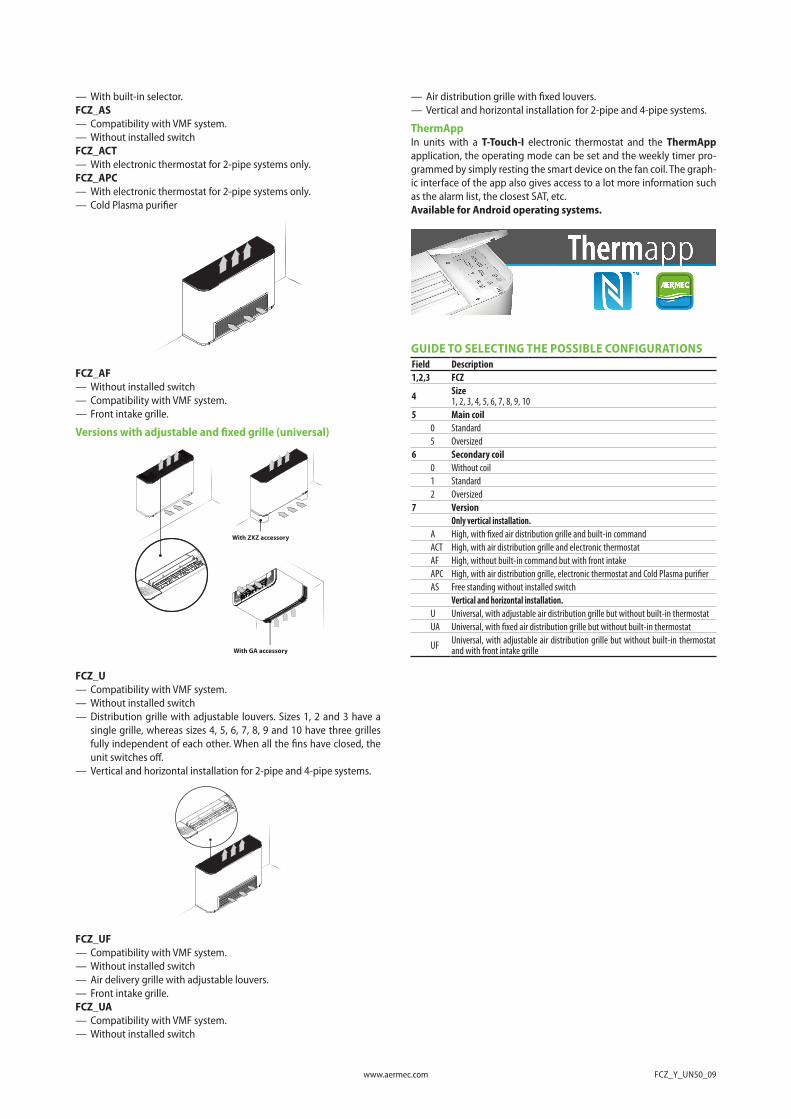
— With built-in selector.FCZ_AS— Compatibility with VMF system.— Without installed switchFCZ_ACT— With electronic thermostat for 2-pipe systems only.FCZ_APC— With electronic thermostat for 2-pipe systems only.— Cold Plasma purifier
FCZ_AF— Without installed switch— Compatibility with VMF system.— Front intake grille.
Versions with adjustable and fixed grille (universal)
With GA accessory
With ZXZ accessory
FCZ_U— Compatibility with VMF system.— Without installed switch— Distribution grille with adjustable louvers. Sizes 1, 2 and 3 have a
single grille, whereas sizes 4, 5, 6, 7, 8, 9 and 10 have three grilles fully independent of each other. When all the fins have closed, the unit switches off.
— Vertical and horizontal installation for 2-pipe and 4-pipe systems.
FCZ_UF— Compatibility with VMF system.— Without installed switch— Air delivery grille with adjustable louvers.— Front intake grille.FCZ_UA— Compatibility with VMF system.— Without installed switch
— Air distribution grille with fixed louvers.— Vertical and horizontal installation for 2-pipe and 4-pipe systems.
ThermAppIn units with a T-Touch-I electronic thermostat and the ThermApp application, the operating mode can be set and the weekly timer pro-grammed by simply resting the smart device on the fan coil. The graph-ic interface of the app also gives access to a lot more information such as the alarm list, the closest SAT, etc.Available for Android operating systems.
GUIDE TO SELECTING THE POSSIBLE CONFIGURATIONSField Description1,2,3 FCZ
4 Size1, 2, 3, 4, 5, 6, 7, 8, 9, 10
5 Main coil0 Standard5 Oversized
6 Secondary coil0 Without coil1 Standard2 Oversized
7 VersionOnly vertical installation.
A High, with fixed air distribution grille and built-in commandACT High, with air distribution grille and electronic thermostatAF High, without built-in command but with front intakeAPC High, with air distribution grille, electronic thermostat and Cold Plasma purifierAS Free standing without installed switch
Vertical and horizontal installation.U Universal, with adjustable air distribution grille but without built-in thermostatUA Universal, with fixed air distribution grille but without built-in thermostat
UF Universal, with adjustable air distribution grille but without built-in thermostat and with front intake grille

FCZ_Y_UN50_09 www.aermec.com
SIZE AVAILABLE FOR VERSIONSize 100 101 102 150 200 201 202 250 300 301 302 350 400 401 402 450 500 501 502 550
Versions produced (by size)
Versions available (by size)
A,AS,U,UA • • • • • • • • • • • • • • • • • • • •ACT,APC • - - • • - - • • - - • • - - • • - - •AF,UF • - - • • - - • • - - • • - - • • - - •
Size 600 601 602 650 700 701 702 750 800 801 802 850 900 901 950 1000 1001Versions produced (by size)
Versions available (by size)
A,AS,U,UA • • • • • • • • • • • • • • • • •ACT,APC • - - • • - - • • - - • • - • • -AF,UF - - - - - - - - - - - - • - • • -
ACCESSORIES Control panelsAER503IR: Flush-mounting thermostat with backlit display, capacitive keypad and infrared receiver, for controlling both brushless fan coils and those with an asynchronous motor. In 2-pipe systems, the thermo-stat can control standard fan coils or those equipped with an electric heater, with air purifying devices (Cold Plasma and germicidal lamp), with radiant plate or with FCZ-D twin delivery (Dualjet). In addition, it can control systems with radiant panels or mixed (fan coil and radiant floor) systems. Being equipped with an infrared receiver, it can, in turn, be controlled by the VMF-IR remote control.PX2Z: On-board electromechanical switch.SA5: air probe kit (L = 15 m) with probe-locking cable grommet.SIT3: Thermostat Interface Card allowing the creation of a network of fan coils (max. 10) commanded by a central control panel (selector or thermostat). Commands the 3 fan speeds and must be installed on each fan coil within the network; receives the commands from the selector or the SIT5 card. In case you decide to install Aermec thermostats and current absorbed by the unit exceeds 0.7 A, you’re obliged to include SIT3 accessory.SIT5: Thermostat Interface Card allowing the creation of a network of fan coils (max. 10) commanded by a central control panel. Commands the 3 fan speeds and up to 2 valves (four pipe systems); sends the ther-mostat's commands to the fan coil network.SW3: Water probe (L = 2.5 m) for controlling the minimum and maxi-mum and to allow automatic seasonal switching for electronic thermo-stats fitted with water side changeover.SW5: water probe kit (L = 15m) with probe-holder connection point, fixing clip and probe-holder from heat exchanger.T-TOUCH: Touch control on board the machine, for controlling fan coils with asynchronous motors. In 2-pipe systems, it can control standard fan coils or those equipped with an electric heater, with air purifying devices or with FCZ-D twin delivery (Dualjet). In 4-pipe systems, only standard fan coils. The ThermApp application is also available for re-mote control with smart devices with the Android operating system.TX: Wall-mounting thermostat for controlling either brushless fan coils or those with asynchronous motors for 2/4 pipe. In 2-pipe systems, the thermostat can control standard fan coils or those equipped with an electric heater, with air purifying devices, radiant plate or FCZ-D twin delivery (Dualjet).TXB: Wall-mounting thermostat for controlling either brushless fan coils or those with asynchronous motors for 2/4 pipe. In 2-pipe systems, the thermostat can control standard fan coils or those equipped with an electric heater, with air purifying devices, radiant plate or FCZ-D twin delivery (Dualjet).WMT05: Electronic thermostat with thermostated ventilation.WMT06: Electronic thermostat with continuous ventilation.WMT10: Electronic thermostat, white, with thermostated or continu-ous ventilation.
VMF systemVMF-E0X: Thermostat to be secured to the side of the fan coil, fitted as standard with an air probe and a water probe.VMF-E19: Thermostat to be secured to the side of the fan coil, fitted as standard with an air probe and a water probe.VMF-E2Z: User interface on the machine, to be combined with the VMF-E0X, VMF-E19 or VMF-E19l accessory.
VMF-E3: Wall mounted user interface, to be combined with accessories VMF-E19, VMF-E19I, VMF-E0X with grids GLF_N/M and GLL_N, can be controlled with VMF-IR control.VMF-E4DX: Wall-mounted user interface. Grey front panel PANTONE 425C (METAL).VMF-E4X: Wall-mounted user interface. Light grey front panel PAN-TONE COOL GRAY 1C.VMF-IR: User interface compatible with the AER503IR, VMF-E3 ther-mostat and with all the grids of cassettes equipped with the infrared receiver compatible with the VMF system.VMF-SW: Water probe (L = 2.5m) used if required in place of the stand-ard unit supplied with the VMF-E0X, VMF-E19 and VMF-E19I thermo-stats for mounting it upstream of the valveVMF-SW1: Additional water probe (L = 2.5m) to be used if required for 4-pipe systems with the VMF-E19 and VMF-E19I thermostats for maxi-mum control in the cold range
Water valvesVCZ_X: 3-way valve kit for single-coil fan coil, RH connections, (VCZ_X4R) or LH (VCZ_X4L) for 4-pipe systems. With totally separate "heat-ing" and "cooling" circuits. This kit consists of two 3-way insulated valves and four connections, complete with electrothermal actuators, insulating shells for the valves, and the relative hydraulic couplings. X4L version for fan coils with LH connections, and X4R for fan coils with RH connections. 230V~50Hz power supply.VCZ: 3-way motorised valve kit. The kit consists of a valve with its in-sulating shell, an actuator and the relative pipe fittings. It can be in-stalled on fan coils with both right and left connections. If the valve is combined with the BCZ5 or BCZ6 condensate drain pan, to ensure a better housing it is possible to remove the 3-way insulating shell. The kit consists of a valve with its insulating shell, an actuator and the rela-tive pipe fittings. It can be installed on fan coils with both right and left connections. If the valve is combined with the BCZ5 or BCZ6 conden-sate drain pan, to ensure a better housing it is possible to remove the insulating shell.VCF44 - 45 - for the secondary coil: The 3-way motorised valve kit for the secondary coil heat only. The kit consists of a valve with its in-sulating shell, actuator and relevant water fittings; it is suitable to be installed on the fan coils with right and left water connections.VCZD: 2-way motorised valve kit. The kit consists of a valve, an actuator and the relative pipe fittings. It can be installed on fan coils with both right and left connections.VJP: Control and balancing combination valve for 2 and 4 pipe systems to install outside the unit, supplied without fittings and hydraulic com-ponents. The valve, which can guarantee a constant water flow rate in the terminal, within its operating range.
(Heating only) additional coilBV: Single row hot water heat exchanger.RX: Armoured electric coil with safety thermostat.
Installation accessoriesPCZ: Metal panel for the unit rear closing. SPCZ brackets are necessary to fix floor standing fan coils.GA: Lower intake grille for encapsulated fan coils. Can also be used in wall-mounted or floor installations, the FIKIT accessory is needed only in the case of floor installation.

www.aermec.com FCZ_Y_UN50_09
FIKIT: Metal supports for vertical installation of the GA grille.DSCZ4: Condensate drainage device.
BCZ: Condensate drip. If the valve is paired with the BCZ5 or BCZ6 con-densate drip tray, the insulating shell can be removed to ensure better housing.AMP: Wall mounting kit
ACCESSORIES COMPATIBILITY Control panelsModel Ver 100 101 102 150 200 201 202 250
AER503IR (1)AF,UF • • • •
AS,U,UA • • • • • • • •
PX2ZAF,UF • • • •AS,U • • • • • • • •
SA5 (2)AF,UF • • • •
AS,U,UA • • • • • • • •SIT3 (3) AS,U,UA • • • • • • • •SIT5 (4) AS,U,UA • • • • • • • •
SW3 (2)AF,AS,UF • • • •
U,UA • • • • • • • •
SW5 (2)AF,UF • • • •
AS,U,UA • • • • • • • •
T-TOUCH (5)AF,UF • • • •AS,U • • • • • • • •
TX (1)AF,UF • • • •
AS,U,UA • • • • • • • •
TXB (5)AF,UF • • • •
AS,U,UA • • • • • • • •WMT05 (1) AF,AS,U,UA,UF • • • •
WMT06 (1)AF,UF • • • •AS,U • • • • • • • •
WMT10 (1)AF,UF • • • •
AS,U,UA • • • • • • • •
Model Ver 300 301 302 350 400 401 402 450
AER503IR (1)AF,UF • • • •
AS,U,UA • • • • • • • •
PX2ZAF,UF • • • •AS,U • • • • • • • •
SA5 (2)AF,UF • • • •
AS,U,UA • • • • • • • •SIT3 (3) AS,U,UA • • • • • • • •SIT5 (4) AS,U,UA • • • • • • • •
SW3 (2)AF,AS,UF • • • •
U,UA • • • • • • • •
SW5 (2)AF,UF • • • •
AS,U,UA • • • • • • • •
T-TOUCH (5)AF,UF • •AS,U • • • • • • • •
TX (1)AF,UF • • • •
AS,U,UA • • • • • • • •
TXB (5)AF,UF • • • •
AS,U,UA • • • • • • • •WMT05 (1) AF,AS,U,UA,UF • • • •
WMT06 (1)AF,UF • • • •AS,U • • • • • • • •
WMT10 (1)AF,UF • • • •
AS,U,UA • • • • • • • •
Model Ver 500 501 502 550 600 601 602 650
AER503IR (1)AF,UF • •
AS,U,UA • • • • • • • •
PX2ZAF,UF • •AS,U • • • • • • • •
SA5 (2)AF,UF • •
AS,U,UA • • • • • • • •SIT3 (3) AS,U,UA • • • • • • • •SIT5 (4) AS,U,UA • • • • • • • •
SW3 (2)AF,UF • •
AS • • • • • •U,UA • • • • • • • •
SW5 (2)AF,UF • •
AS,U,UA • • • • • • • •
T-TOUCH (5)AF,UF • •AS,U • • • • • • • •

FCZ_Y_UN50_09 www.aermec.com
Model Ver 500 501 502 550 600 601 602 650
TX (1)AF,UF • •
AS,U,UA • • • • • • • •
TXB (5)AF,UF • •
AS,U,UA • • • • • • • •
WMT05 (1)AF,UF • •
AS,U,UA • • • •
WMT06 (1)AF,UF • •AS,U • • • • • • • •
WMT10 (1)AF,UF • •
AS,U,UA • • • • • • • •
Model Ver 700 701 702 750 800 801 802 850AER503IR (1) AS,U,UA • • • • • • • •PX2Z AS,U • • • • • • • •SA5 (2) AS,U,UA • • • • • • • •SIT3 (3) AS,U,UA • • • • • • • •SIT5 (4) AS,U,UA • • • • • • • •SW3 (2) AS,U,UA • • • • • • • •SW5 (2) AS,U,UA • • • • • • • •T-TOUCH (5) AS,U • • • • • • • •TX (1) AS,U,UA • • • • • • • •TXB (5) AS,U,UA • • • • • • • •WMT05 (1) AS,U,UA • • • •WMT06 (1) AS,U • • • • • • • •WMT10 (1) AS,U,UA • • • • • • • •
Model Ver 900 901 950 1000 1001
AER503IR (1)AF,UF • •
AS,U,UA • • • • •
PX2ZAF,UF •AS,U • • • • •
SA5 (2)AF,UF • •
AS,U,UA • • • • •
SIT3 (3)AF,UF •
AS,U,UA • • • • •
SIT5 (4)AF,UF •
AS,U,UA • • • • •
SW3 (2)AF,UF • •
AS • • • •U,UA • • • • •
SW5 (2)AF,UF • •
AS,U,UA • • • • •
T-TOUCH (5)AF,UF • • •AS,U • • • • •
TX (1)AF,UF • •
AS,U,UA • • • • •
TXB (5)AF,UF • • •
AS,U,UA • • • • •WMT05 (1) AF,AS,U,UA,UF • • •
WMT06 (1)AF,UF • • •AS,U • • • • •
WMT10 (1)AF,UF • • •
AS,U,UA • • • • •
(1) Wall-mounting. If the unit intake exceeds 0.7A, or several units need to be managed with a single thermostat, board SIT3 and/or SIT5 is required.(2) Probe for AER503IR-TX thermostats, if fitted.(3) Cards for AER503IR-TX thermostats, if present, to be installed if the unit absorption exceeds 0,7 Ampere.(4) Probe for AER503IR-TX thermostats, if fitted.(5) Installation on the fan coil.
VMF systemFor more information about VMF system, refer to the dedicated documentation. VMF systemModel Ver 100 101 102 150 200 201 202 250 300 301
VMF-E0X (1)AF,UF • • • • •
AS,U,UA • • • • • • • • • •
VMF-E19 (1)AF,UF • • • • •
AS,U,UA • • • • • • • • • •
VMF-E2ZAF,UF • • • • •
AS,U,UA • • • • • • • • • •
VMF-E3AF,UF • • • • •U,UA • • • • • • • • • •

www.aermec.com FCZ_Y_UN50_09
Model Ver 100 101 102 150 200 201 202 250 300 301
VMF-E4DXAF,UF • • • • •
AS,U,UA • • • • • • • • • •
VMF-E4XAF,UF • • • • •
AS,U,UA • • • • • • • • • •
VMF-IRAF,UF • • • • •U,UA • • • • • • • • • •
VMF-SWAF,UF • • • • •AS,U • • • • • • • • • •
VMF-SW1AF,UF • • • • •AS,U • • • • • • • • • •
Model Ver 302 350 400 401 402 450 500 501 502 550
VMF-E0X (1)AF,UF • • • • •
AS,U,UA • • • • • • • • • •
VMF-E19 (1)AF,UF • • • • •
AS,U,UA • • • • • • • • • •
VMF-E2ZAF,UF • • • • •
AS,U,UA • • • • • • • • • •
VMF-E3AF,UF • • • • •U,UA • • • • • • • • • •
VMF-E4DXAF,UF • • • • •
AS,U,UA • • • • • • • • • •
VMF-E4XAF,UF • • • • •
AS,U,UA • • • • • • • • • •
VMF-IRAF,UF • • • • •U,UA • • • • • • • • • •
VMF-SWAF,UF • • • • •AS,U • • • • • • • • • •
VMF-SW1AF,UF • • • • •AS,U • • • • • • • • • •
Model Ver 600 601 602 650 700 701 702 750 800 801
VMF-E0X (1)AS,UA • • • • • • • • • •
U • • • • •
VMF-E19 (1)AS,UA • • • • • • • • • •
U • • • • •
VMF-E2ZAS,UA • • • • • • • • • •
U • • • • •
VMF-E3AF,UF • • • • •U,UA • • • • • • • • • •
VMF-E4DXAS,UA • • • • • • • • • •
U • • • • •
VMF-E4XAS,UA • • • • • • • • • •
U • • • • •
VMF-IRAF,UF • • • • •U,UA • • • • • • • • • •
VMF-SWAS • • • • • • • • • •U • • • • •
VMF-SW1AS • • • • • • • • • •U • • • • •
Model Ver 802 850 900 901 950 1000 1001
VMF-E0X (1)AF,UF •AS,UA • • • • • • •
U • • • • • •
VMF-E19 (1)AF,UF •AS,UA • • • • • • •
U • • • • • •
VMF-E2ZAF,UF •AS,UA • • • • • • •
U • • • • • •
VMF-E3AF • • •
U,UA • • • • • • •UF • • • •
VMF-E4DXAF,UF •AS,UA • • • • • • •
U • • • • • •
VMF-E4XAF,UF •AS,UA • • • • • • •
U • • • • • •

FCZ_Y_UN50_09 www.aermec.com
Model Ver 802 850 900 901 950 1000 1001
VMF-IRAF • • •
U,UA • • • • • • •UF • • • •
VMF-SWAF,UF •
AS • • • • • • •U • • • • • •
VMF-SW1AF,UF •
AS • • • • • • •U • • • • • •
(1) Also the accessory VMF-SIT3V is mandatory if the unit exceeds 0.7 Amperes.
Water valves 3 way valve kit
100 101 102 150 200 201 202 250 300 301 302 350 400 401 402 450
Main coil VCZ41VCZ4124
VCZ41VCZ4124
VCZ41VCZ4124
VCZ41VCZ4124
VCZ41VCZ4124
VCZ41VCZ4124
VCZ41VCZ4124
VCZ41VCZ4124
VCZ42VCZ4224
VCZ42VCZ4224
VCZ42VCZ4224
VCZ42VCZ4224
VCZ42VCZ4224
VCZ42VCZ4224
VCZ42VCZ4224
VCZ42VCZ4224
Secondary coil -VCF44
VCF4424VCF44
VCF4424- -
VCF44VCF4424
VCF44VCF4424
- -VCF44
VCF4424VCF44
VCF4424- -
VCF44VCF4424
VCF44VCF4424
-
Additional coil “BV” VCF44VCF4424
- - -VCF44
VCF4424- - -
VCF44VCF4424
- - -VCF44
VCF4424- - -
500 501 502 550 600 601 602 650 700 701 702 750 800 801 802 850
Main coil VCZ42VCZ4224
VCZ42VCZ4224
VCZ42VCZ4224
VCZ42VCZ4224
VCZ42VCZ4224
VCZ42VCZ4224
VCZ42VCZ4224
VCZ42VCZ4224
VCZ42VCZ4224
VCZ42VCZ4224
VCZ42VCZ4224
VCZ42VCZ4224
VCZ42VCZ4224
VCZ42VCZ4224
VCZ42VCZ4224
VCZ42VCZ4224
Secondary coil -VCF44
VCF4424VCF44
VCF4424- -
VCF44VCF4424
VCF44VCF4424
- -VCF44
VCF4424VCF44
VCF4424- -
VCF44VCF4424
VCF44VCF4424
-
Additional coil “BV” VCF44VCF4424
- - -VCF44
VCF4424- - -
VCF44VCF4424
- - -VCF44
VCF4424- - -
900 901 950 1000 1001
Main coil VCZ43VCZ4324
VCZ43VCZ4324
VCZ43VCZ4324
VCZ43VCZ4324
VCZ43VCZ4324
Secondary coil -VCF45
VCF4524- -
VCF45VCF4524
Additional coil “BV” VCF45VCF4524
- -VCF45
VCF4524-
2 way valve kit100 101 102 150 200 201 202 250 300 301 302 350 400 401 402 450
Main coil VCZD1VCZD124
VCZD1VCZD124
VCZD1VCZD124
VCZD1VCZD124
VCZD1VCZD124
VCZD1VCZD124
VCZD1VCZD124
VCZD1VCZD124
VCZD2VCZD224
VCZD2VCZD224
VCZD2VCZD224
VCZD2VCZD224
VCZD2VCZD224
VCZD2VCZD224
VCZD2VCZD224
VCZD2VCZD224
Secondary coil -VCFD4
VCFD424VCFD4
VCFD424- -
VCFD4VCFD424
VCFD4VCFD424
- -VCFD4
VCFD424VCFD4
VCZD424- -
VCFD4VCFD424
VCFD4VCFD424
-
Additional coil “BV” VCFD4VCFD424
- - -VCFD4
VCFD424- - -
VCFD4VCFD424
- - -VCFD4
VCFD424- - -
500 501 502 550 600 601 602 650 700 701 702 750 800 801 802 850
Main coil VCZD2VCZD224
VCZD2VCZD224
VCZD2VCZD224
VCZD2VCZD224
VCZD2VCZD224
VCZD2VCZD224
VCZD2VCZD224
VCZD2VCZD224
VCZD2VCZD224
VCZD2VCZD224
VCZD2VCZD224
VCZD2VCZD224
VCZD2VCZD224
VCZD2VCZD224
VCZD2VCZD224
VCZD2VCZD224
Secondary coil -VCFD4
VCFD424VCFD4
VCFD424- -
VCFD4VCFD424
VCFD4VCFD424
- -VCFD4
VCFD424VCFD4
VCFD424- -
VCFD4VCFD424
VCFD4VCFD424
-
Additional coil “BV” VCFD4VCFD424
- - -VCFD4
VCFD424- - -
VCFD4VCFD424
- - -VCFD4
VCFD424- - -
900 901 950 1000 1001
Main coil VCZD3VCZD324
VCZD3VCZD324
VCZD3VCZD324
VCZD3VCZD324
VCZD3VCZD324
Secondary coil -VCFD4
VCFD424- -
VCFD4VCFD424
Additional coil “BV” VCFD4VCFD424
- -VCFD4
VCFD424-
Valve Kit for 4 pipe systems - Requires a thermostat with valve managementModel Ver 100 101 102 150 200 201 202 250VCZ1X4L (1) AF,AS,U,UA,UF • • • •VCZ1X4R (1) AF,AS,U,UA,UF • • • •
Model Ver 300 301 302 350 400 401 402 450VCZ2X4L (1) AF,AS,U,UA,UF • • • •VCZ2X4R (1) AF,AS,U,UA,UF • • • •

www.aermec.com FCZ_Y_UN50_09
Model Ver 500 501 502 550 600 601 602 650
VCZ2X4L (1)AF,UF • •
AS,U,UA • • • •
VCZ2X4R (1)AF,UF • •
AS,U,UA • • • •
Model Ver 700 701 702 750 800 801 802 850VCZ2X4L (1) AS,U,UA • • • •VCZ2X4R (1) AS,U,UA • • • •
Model Ver 900 901 950 1000 1001VCZ3X4L (1) AF,AS,U,UA,UF • • •VCZ3X4R (1) AF,AS,U,UA,UF • • •
(1) The valves can be combined with the units if there is a control panel for managing them.
Combined Adjustment and Balancing Valve KitModel Ver 100 101 102 150 200 201 202 250
VJP060 (1)ACT,APC • • • •AS,U,UA • • • • • • • •
VJP060M (2)ACT,APC • • • •AS,U,UA • • • • • • • •
Model Ver 300 301 302 350 400 401 402 450
VJP060 (1)ACT,APC • •AS,U,UA • • • •
VJP060M (2)ACT,APC • •AS,U,UA • • • •
VJP090 (1)ACT,APC • •AS,U,UA • • • •
VJP090M (2)ACT,APC • •AS,U,UA • • • •
Model Ver 500 501 502 550 600 601 602 650
VJP090 (1)ACT,APC • • • •AS,U,UA • • • • • • • •
VJP090M (2)ACT,APC • • • •AS,U,UA • • • • • • • •
VJP150 (1)ACT,APC • •AS,U,UA • • • •
VJP150M (2)ACT,APC • •AS,U,UA • • • •
Model Ver 700 701 702 750 800 801 802 850
VJP150 (1)ACT,APC • • • •AS,U,UA • • • • • • • •
VJP150M (2)ACT,APC • • • •AS,U,UA • • • • • • • •
Model Ver 900 901 950 1000 1001
VJP150 (1)ACT,APC • • •AS,U,UA • • • • •
VJP150M (2)ACT,APC • • •AS,U,UA • • • • •
(1) 230V~50Hz(2) 24V
(Heating only) additional coil Heating only additional coilModel Ver 100 101 102 150 200 201 202 250BV117 (1) A,AF,AS,U,UA,UF •BV122 (1) A,AF,AS,U,UA,UF •
Model Ver 300 301 302 350 400 401 402 450BV132 (1) A,AF,AS,U,UA,UF •BV142 (1) A,AF,AS,U,UA,UF •
Model Ver 500 501 502 550 600 601 602 650BV142 (1) A,AF,AS,U,UA,UF •BVZ800 (1) A,AS,U,UA •
Model Ver 700 701 702 750 800 801 802 850BVZ800 (1) A,AS,U,UA • •
Model Ver 900 901 950 1000 1001BV162 (1) A,AF,AS,U,UA,UF • •
(1) Not available for sizes with oversized main coil.

FCZ_Y_UN50_09 www.aermec.com
Electric coil - Requires a thermostat with heater management. Not available for sizes with an oversized main coil.Model Ver 100 101 102 150 200 201 202 250RX17 (1) AF,AS,U,UA,UF •RX22 (1) AF,AS,U,UA,UF •
Model Ver 300 301 302 350 400 401 402 450RX32 (1) AF,AS,U,UA,UF •RX42 (1) AF,AS,U,UA,UF •
Model Ver 500 501 502 550 600 601 602 650RX52 (1) AF,AS,U,UA,UF •RXZ800 (1) AS,U,UA •
Model Ver 700 701 702 750 800 801 802 850RXZ800 (1) AS,U,UA • •
Model Ver 900 901 950 1000 1001RX62 (1) AF,AS,U,UA,UF • •
(1) Requires a thermostat with heater management. Not available for sizes with an oversized main coil. The PCR1 or PCR2 appliance must also be provided depending on the unit.
Installation accessories Wall mounting kit
Ver 100 101 102 150 200 201 202 250U,UA AMP20 AMP20 AMP20 AMP20 AMP20 AMP20 AMP20 AMP20
UF AMP20 - - AMP20 AMP20 - - AMP20
Ver 300 301 302 350 400 401 402 450U,UA AMP20 AMP20 AMP20 AMP20 AMP20 AMP20 AMP20 AMP20
UF AMP20 - - AMP20 AMP20 - - AMP20
Ver 500 501 502 550 600 601 602 650U,UA AMP20 AMP20 AMP20 AMP20 AMPZ AMPZ AMPZ AMPZ
UF AMP20 - - AMP20 - - - -
The accessory cannot be fitted on the configurations indicated with -
Ver 700 701 702 750 800 801 802 850U,UA AMPZ AMPZ AMPZ AMPZ AMPZ AMPZ AMPZ AMPZ
Ver 900 901 950 1000 1001U,UA AMPZ AMPZ AMPZ AMPZ AMPZ
Condensate recirculation deviceModel Ver 100 101 102 150 200 201 202 250
DSCZ4 (1)A,AS,U,UA • • • • • • • •
ACT,APC • • • •
Model Ver 300 301 302 350 400 401 402 450
DSCZ4 (1)A,AS,U,UA • • • • • • • •
ACT,APC • • • •
Model Ver 500 501 502 550 600 601 602 650
DSCZ4 (1)A,AS,U,UA • • • • • • • •
ACT,APC • • • •
Model Ver 700 701 702 750 800 801 802 850
DSCZ4 (1)A,AS,U,UA • • • • • • • •
ACT,APC • • • •
Model Ver 900 901 950 1000 1001
DSCZ4 (1)A,AS,U,UA • • • • •
ACT,APC • • •
(1) DSC4 cannot be mounted if even just one of these accessories is also installed: AMP - AMPZ valve VCZ1-2-3-4 X4L/R and all the condensate collection trays.
Condensate dripModel Ver 100 101 102 150 200 201 202 250
BCZ4 (1)A,AS,U,UA • • • • • • • •
ACT,APC • • • •
BCZ5 (2)A,AS,U,UA • • • • • • • •
ACT,APC • • • •
Model Ver 300 301 302 350 400 401 402 450
BCZ4 (1)A,AS,U,UA • • • • • • • •
ACT,APC • • • •
BCZ5 (2)A,AS,U,UA • • • • • • • •
ACT,APC • • • •
Model Ver 500 501 502 550 600 601 602 650
BCZ4 (1)A,AS,U,UA • • • • • • • •
ACT,APC • • • •
BCZ5 (2)A,AS,U,UA • • • • • • • •
ACT,APC • • • •

www.aermec.com FCZ_Y_UN50_09
Model Ver 700 701 702 750 800 801 802 850
BCZ4 (1)A,AS,U,UA • • • • • • • •
ACT,APC • • • •
BCZ5 (2)A,AS,U,UA • • • • • • • •
ACT,APC • • • •
Model Ver 900 901 950 1000 1001
BCZ4 (1)A,AS,U,UA • • • • •
ACT,APC • • •
BCZ6 (2)A,AS,U,UA • • • • •
ACT,APC • • •
(1) For vertical installation.(2) For horizontal installation.
Panel closing the rear of the unitModel Ver 100 101 102 150 200 201 202 250
PCZ100A,AS,U,UA • • • •
ACT,APC • •
PCZ200A,AS,U,UA • • • •
ACT,APC • •
Model Ver 300 301 302 350 400 401 402 450
PCZ300A,AS,U,UA • • • •
ACT,APC • •
PCZ500A,AS,U,UA • • • •
ACT,APC • •
Model Ver 500 501 502 550 600 601 602 650
PCZ500A,AS,U,UA • • • •
ACT,APC • •
PCZ800A,AS,U,UA • • • •
ACT,APC • •
Model Ver 700 701 702 750 800 801 802 850
PCZ800A,AS,U,UA • • • • • • • •
ACT,APC • • • •
Model Ver 900 901 950 1000 1001
PCZ1000A,AS,U,UA • • • • •
ACT,APC • • •
Lower intake grilleModel Ver 100 101 102 150 200 201 202 250GA100 U,UA • • • •GA200 U,UA • • • •
Model Ver 300 301 302 350 400 401 402 450GA300 U,UA • • • •GA500 U,UA • • • •
Model Ver 500 501 502 550 600 601 602 650GA500 U,UA • • • •GA800 U,UA • • • •
Model Ver 700 701 702 750 800 801 802 850GA800 U,UA • • • • • • • •
Model Ver 900 901 950 1000 1001GA800 U,UA • • • • •
Supports to be combined with the ornamental grille (GA) for floor installation of the fan coilModel Ver 100 101 102 150 200 201 202 250
FIKIT100A,AS,U,UA • • • •
ACT,AF,APC,UF • •
FIKIT200A,AS,U,UA • • • •
ACT,AF,APC,UF • •
Model Ver 300 301 302 350 400 401 402 450
FIKIT300A,AS,U,UA • • • •
ACT,AF,APC,UF • •
FIKIT500A,AS,U,UA • • • •
ACT,AF,APC,UF • •
Model Ver 500 501 502 550 600 601 602 650
FIKIT500A,AS,U,UA • • • •
ACT,AF,APC,UF • •
FIKIT800A,AS,U,UA • • • •
ACT,APC • •

FCZ_Y_UN50_09 www.aermec.com
Model Ver 700 701 702 750 800 801 802 850
FIKIT800ACT,APC • • • •
U,UA • • • • • • • •
Model Ver 900 901 950 1000 1001
FIKIT800A,AS,U,UA • • • • •
ACT,AF,APC,UF • • •
Pair of stylish structural feetModel Ver 100 101 102 150 200 201 202 250
ZXZA,AS,U,UA • • • • • • • •
ACT,APC • • • •
Model Ver 300 301 302 350 400 401 402 450
ZXZA,AS,U,UA • • • • • • • •
ACT,APC • • • •
Model Ver 500 501 502 550 600 601 602 650
ZXZA,AS,U,UA • • • • • • • •
ACT,APC • • • •
Model Ver 700 701 702 750 800 801 802 850
ZXZA,AS,U,UA • • • • • • • •
ACT,APC • • • •
Model Ver 900 901 950 1000 1001
ZXZA,AS,U,UA • • • • •
ACT,APC • • •
PERFORMANCE SPECIFICATIONS2-pipe
FCZ100 FCZ150 FCZ200 FCZ250 FCZ300 FCZ350 FCZ400 FCZ450 FCZ500 FCZ5501 2 3 1 2 3 1 2 3 1 2 3 1 2 3 1 2 3 1 2 3 1 2 3 1 2 3 1 2 3L M H L M H L M H L M H L M H L M H L M H L M H L M H L M H
Heating performance 70 °C / 60 °C (1)Heating capacity kW 1,45 2,00 2,40 1,55 2,19 2,65 2,02 2,95 3,70 2,20 3,18 4,05 3,47 4,46 5,50 3,77 4,92 6,15 4,32 5,74 7,15 4,57 6,29 7,82 5,27 7,31 8,50 5,82 8,34 9,75Water flow rate system side l/h 125 172 206 136 192 232 177 258 324 193 278 355 304 391 482 330 431 539 379 503 627 400 551 685 462 641 745 510 731 855Pressure drop system side kPa 4 7 9 5 9 12 6 12 18 7 15 23 7 12 18 8 14 20 9 16 24 6 11 16 12 21 28 10 20 26Heating performance 45 °C / 40 °C (2)Heating capacity kW 0,72 0,99 1,19 0,77 1,09 1,31 1,00 1,46 1,84 1,09 1,58 2,01 1,72 2,21 2,73 1,87 2,44 3,06 2,14 2,85 3,55 2,27 3,12 3,88 2,62 3,63 4,22 2,89 4,14 4,85Water flow rate system side l/h 126 173 207 134 189 229 174 254 319 190 274 350 299 385 475 325 425 531 373 495 617 394 543 675 455 631 734 502 720 842Pressure drop system side kPa 4 7 10 5 9 12 6 12 18 8 15 22 8 12 18 8 14 20 10 16 24 6 11 16 12 21 28 10 20 26Cooling performance 7 °C / 12 °C (3)Cooling capacity kW 0,65 0,84 1,00 0,80 1,06 1,27 0,89 1,28 1,60 1,06 1,55 1,94 1,68 2,17 2,65 1,89 2,46 3,02 2,20 2,92 3,60 2,41 3,21 4,03 2,68 3,69 4,25 2,91 4,13 4,79Sensible cooling capacity kW 0,51 0,69 0,83 0,57 0,80 0,97 0,71 1,05 1,33 0,79 1,20 1,52 1,26 1,65 2,04 1,33 1,76 2,18 1,59 2,14 2,67 1,69 2,30 2,90 1,94 2,73 3,18 2,07 2,98 3,49Water flow rate system side l/h 112 144 172 138 182 219 153 221 275 182 267 334 288 374 456 350 460 560 379 503 619 414 552 694 460 634 731 501 711 824Pressure drop system side kPa 4 6 8 6 12 13 6 12 18 8 17 25 8 13 18 11 18 25 10 16 24 9 15 22 13 22 29 12 22 28FanType type CentrifugalFan motor type AsynchronousNumber no. 1 1 1 1 2 2 2 2 2 2Air flow rate m³/h 110 160 200 110 160 200 140 220 290 140 220 290 260 350 450 260 350 450 330 460 600 330 460 600 400 600 720 400 600 720Input power W 19 29 35 19 29 35 25 29 33 25 29 33 25 33 44 25 33 44 30 43 57 30 43 57 38 52 76 38 52 76Electrical wiring V1 V2 V3 V1 V2 V3 V1 V2 V3 V1 V2 V3 V1 V2 V3 V1 V2 V3 V1 V2 V3 V1 V2 V3 V1 V2 V3 V1 V2 V3Fan coil sound data (4)Sound power level dB(A) 31,0 38,0 45,0 31,0 38,0 45,0 35,0 46,0 51,0 35,0 46,0 51,0 34,0 41,0 48,0 34,0 41,0 48,0 37,0 44,0 51,0 37,0 44,0 51,0 42,0 51,0 56,0 42,0 51,0 56,0Sound pressure dB(A) 23,0 30,0 37,0 23,0 30,0 37,0 27,0 38,0 43,0 27,0 38,0 43,0 26,0 33,0 40,0 26,0 33,0 40,0 29,0 36,0 43,0 29,0 36,0 43,0 34,0 43,0 48,0 34,0 43,0 48,0Diametre hydraulic fittingsMain coil Ø 1/2” 1/2” 1/2” 1/2” 3/4” 3/4” 3/4” 3/4” 3/4” 3/4”Power supplyPower supply 230V~50Hz

www.aermec.com FCZ_Y_UN50_09
FCZ600 FCZ650 FCZ700 FCZ750 FCZ800 FCZ850 FCZ900 FCZ950 FCZ10001 2 3 1 2 3 1 2 3 1 2 3 1 2 3 1 2 3 1 2 3 1 2 3 1 2 3L M H L M H L M H L M H L M H L M H L M H L M H L M H
Heating performance 70 °C / 60 °C (1)Heating capacity kW 6,50 8,10 10,00 7,19 9,15 11,50 8,10 9,80 11,00 9,10 11,30 12,50 9,80 10,80 12,00 11,30 12,35 14,00 10,77 13,35 15,14 11,20 14,42 17,10 12,53 15,24 17,02Water flow rate system side l/h 570 710 877 631 802 1008 710 860 964 798 991 1096 859 947 1052 991 1083 1227 945 1171 1328 982 1264 1500 1101 1337 1493Pressure drop system side kPa 12 18 26 14 21 31 17 24 29 10 15 18 22 27 32 17 20 25 12 17 22 16 24 33 22 32 38Heating performance 45 °C / 40 °C (2)Heating capacity kW 3,32 4,03 4,97 3,57 4,55 5,72 4,03 4,87 5,47 4,52 5,62 6,21 4,87 5,37 5,97 5,62 6,14 6,96 5,35 6,64 7,53 5,57 7,17 8,50 6,24 7,58 8,46Water flow rate system side l/h 561 699 863 621 790 993 699 846 950 786 975 1079 846 932 1036 975 1066 1209 930 1152 1307 967 1245 1476 1084 1316 1469Pressure drop system side kPa 12 18 26 14 20 31 16 24 29 10 14 18 22 26 32 6 20 25 12 17 22 15 24 33 22 31 38Cooling performance 7 °C / 12 °C (3)Cooling capacity kW 3,22 3,90 4,65 3,95 4,80 5,67 3,92 4,89 5,50 4,27 5,34 6,14 4,84 5,66 6,10 5,26 6,29 6,91 4,29 5,00 6,91 5,77 7,32 8,60 5,69 6,88 7,62Sensible cooling capacity kW 2,56 3,17 3,92 2,78 3,43 4,12 2,99 3,76 4,30 3,20 4,05 4,72 3,72 4,42 4,83 4,00 4,83 5,36 2,97 3,78 5,68 3,80 4,87 5,78 4,42 5,34 5,53Water flow rate system side l/h 554 671 800 595 825 975 675 841 946 734 918 1056 833 974 1049 904 1082 1189 738 860 1189 992 1259 1479 979 1183 1311Pressure drop system side kPa 14 19 26 15 21 28 16 24 30 10 14 18 20 26 30 14 20 23 10 12 22 15 22 30 22 31 36FanType type CentrifugalFan motor type AsynchronousNumber no. 3 3 3 3 3 3 3 3 3Air flow rate m³/h 520 720 920 520 720 920 700 930 1140 700 930 1140 900 1120 1300 900 1120 1300 700 930 1140 700 930 1140 900 1120 1300Input power W 38 60 91 38 60 91 59 80 106 59 80 106 80 100 131 80 100 131 59 80 106 59 80 106 80 100 131Electrical wiring V1 V2 V3 V1 V2 V3 V1 V2 V3 V1 V2 V3 V1 V2 V3 V1 V2 V3 V1 V2 V3 V1 V2 V3 V1 V2 V3Fan coil sound data (4)Sound power level dB(A) 42,0 51,0 57,0 42,0 51,0 57,0 50,0 57,0 62,0 50,0 57,0 62,0 56,0 61,0 66,0 56,0 61,0 66,0 51,0 57,0 62,0 51,0 57,0 62,0 56,0 61,0 66,0Sound pressure dB(A) 34,0 43,0 49,0 34,0 43,0 49,0 42,0 49,0 54,0 42,0 49,0 54,0 48,0 53,0 58,0 48,0 53,0 58,0 43,0 49,0 54,0 43,0 49,0 54,0 48,0 53,0 58,0Diametre hydraulic fittingsMain coil Ø 3/4”Power supplyPower supply 230V~50Hz
(1) Room air temperature 20 °C d.b.; Water (in/out) 70 °C/60 °C(2) Room air temperature 20°C d.b.; Water (in/out) 45°C/40°C; EUROVENT(3) Room air temperature 27°C d.b./19°C w.b.; Water (in/out) 7 °C/12 °C; EUROVENT(4) Aermec determines the sound power value on the basis of measurements taken in accordance with standard UNI EN 16583:15, respecting the Eurovent certification.4-pipe
FCZ101 FCZ201 FCZ301 FCZ401 FCZ501 FCZ601 FCZ701 FCZ801 FCZ901 FCZ10011 2 3 1 2 3 1 2 3 1 2 3 1 2 3 1 2 3 1 2 3 1 2 3 1 2 3 1 2 3L M H L M H L M H L M H L M H L M H L M H L M H L M H L M H
Heating performance 65 °C / 55 °C (1)Heating capacity kW 0,75 1,01 1,17 1,02 1,35 1,60 1,80 2,18 2,56 2,21 2,65 3,12 2,59 3,34 3,73 2,96 3,67 4,36 3,66 4,29 4,94 4,20 4,79 5,35 4,73 5,63 5,72 4,85 5,56 6,08Water flow rate system side l/h 65 89 102 89 118 140 158 191 224 186 232 273 227 293 327 259 321 381 320 375 437 368 419 467 414 492 501 424 487 532Pressure drop system side kPa 2 4 4 4 8 10 16 23 30 4 6 8 6 8 10 8 12 16 11 14 18 16 20 24 8 12 12 10 14 16Cooling performance 7 °C / 12 °C (2)Cooling capacity kW 0,65 0,84 1,00 0,89 1,28 1,60 1,68 2,17 2,65 2,20 2,92 3,60 2,68 3,69 4,25 3,22 3,90 4,65 3,92 4,89 5,50 4,84 5,66 6,10 4,29 5,00 6,91 5,69 6,88 7,62Sensible cooling capacity kW 0,51 0,69 0,83 0,71 1,05 1,33 1,26 1,65 2,04 1,59 2,14 2,67 1,94 2,73 3,18 2,56 3,17 3,92 2,99 3,76 4,30 3,72 4,42 4,83 2,97 3,78 5,68 4,42 5,34 5,53Water flow rate system side l/h 112 144 172 153 221 275 288 374 456 379 503 619 460 634 731 554 671 800 675 841 946 833 974 1049 738 860 1189 979 1183 1311Pressure drop system side kPa 4 6 8 6 12 18 8 13 18 10 16 24 13 22 29 14 19 26 16 24 30 20 26 30 10 12 22 22 31 36FanType type CentrifugalFan motor type AsynchronousNumber no. 1 1 2 2 2 3 3 3 3 3Air flow rate m³/h 110 160 200 140 220 290 260 350 450 330 460 600 400 600 720 520 720 920 700 930 1140 900 1120 1300 700 930 1140 900 1120 1300Input power W 19 29 35 25 29 33 25 33 44 30 43 57 38 52 76 38 60 91 59 80 106 80 100 131 59 80 106 80 100 131Electrical wiring V1 V2 V3 V1 V2 V3 V1 V2 V3 V1 V2 V3 V1 V2 V3 V1 V2 V3 V1 V2 V3 V1 V2 V3 V1 V2 V3 V1 V2 V3Fan coil sound data (3)Sound power level dB(A) 31,0 38,0 45,0 35,0 46,0 51,0 34,0 41,0 48,0 37,0 44,0 51,0 42,0 51,0 56,0 42,0 51,0 57,0 50,0 57,0 62,0 56,0 61,0 66,0 51,0 57,0 62,0 56,0 61,0 66,0Sound pressure dB(A) 23,0 30,0 37,0 27,0 38,0 43,0 26,0 33,0 40,0 29,0 36,0 43,0 34,0 43,0 48,0 34,0 43,0 49,0 42,0 49,0 54,0 48,0 53,0 58,0 43,0 49,0 54,0 48,0 53,0 58,0Diametre hydraulic fittingsMain coil Ø 1/2” 1/2” 3/4” 3/4” 3/4” 3/4” 3/4” 3/4” 3/4” 3/4”Secondary coil Ø 1/2”Power supplyPower supply 230V~50Hz
(1) Room air temperature 20°C d.b.; Water (in/out) 65 °C/55 °C; EUROVENT(2) Room air temperature 27°C d.b./19°C w.b.; Water (in/out) 7 °C/12 °C; EUROVENT(3) Aermec determines the sound power value on the basis of measurements taken in accordance with standard UNI EN 16583:15, respecting the Eurovent certification.
FCZ_Y_UN50_09 www.aermec.com
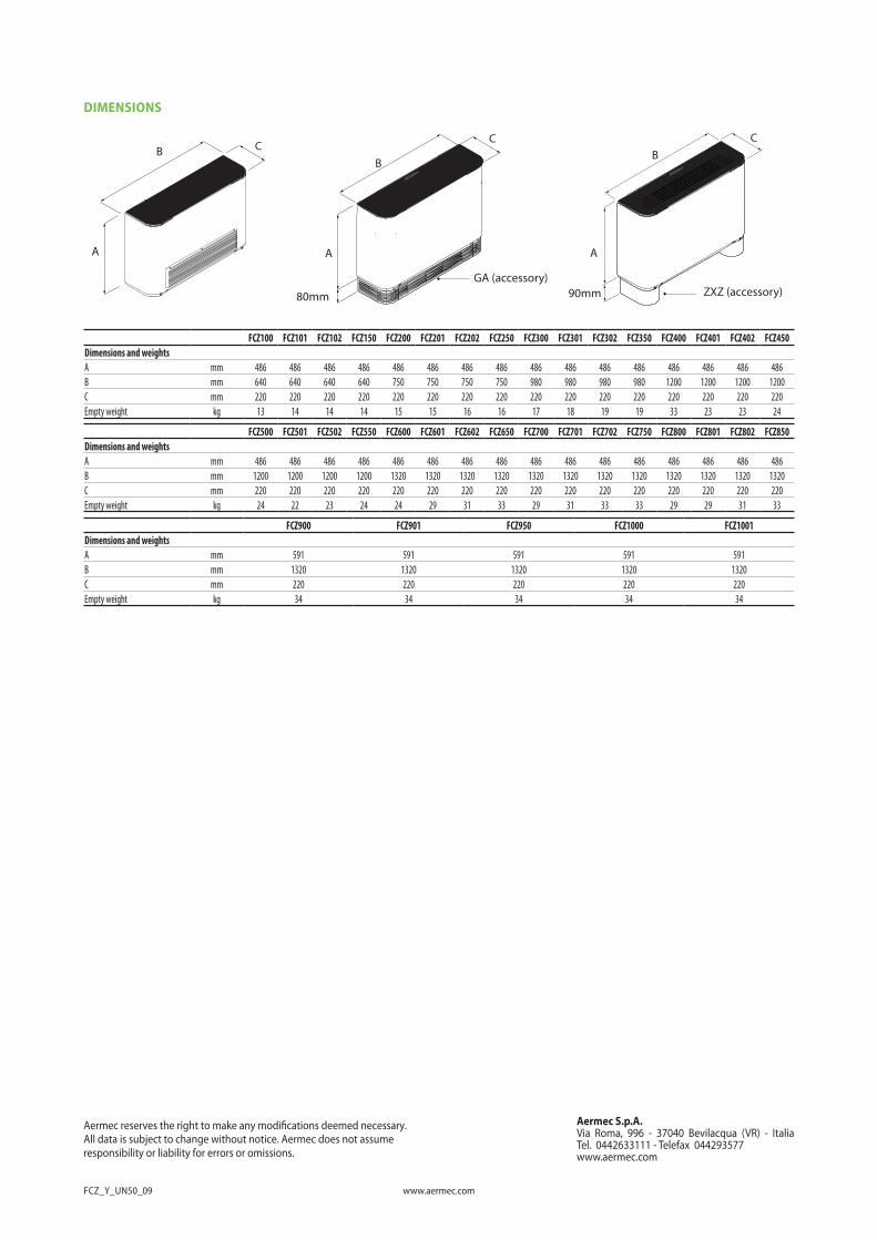
DIMENSIONS
BB
AA
CB
A
CC
80mm 90mmGA (accessory)
ZXZ (accessory)
FCZ100 FCZ101 FCZ102 FCZ150 FCZ200 FCZ201 FCZ202 FCZ250 FCZ300 FCZ301 FCZ302 FCZ350 FCZ400 FCZ401 FCZ402 FCZ450Dimensions and weightsA mm 486 486 486 486 486 486 486 486 486 486 486 486 486 486 486 486B mm 640 640 640 640 750 750 750 750 980 980 980 980 1200 1200 1200 1200C mm 220 220 220 220 220 220 220 220 220 220 220 220 220 220 220 220Empty weight kg 13 14 14 14 15 15 16 16 17 18 19 19 33 23 23 24
FCZ500 FCZ501 FCZ502 FCZ550 FCZ600 FCZ601 FCZ602 FCZ650 FCZ700 FCZ701 FCZ702 FCZ750 FCZ800 FCZ801 FCZ802 FCZ850Dimensions and weightsA mm 486 486 486 486 486 486 486 486 486 486 486 486 486 486 486 486B mm 1200 1200 1200 1200 1320 1320 1320 1320 1320 1320 1320 1320 1320 1320 1320 1320C mm 220 220 220 220 220 220 220 220 220 220 220 220 220 220 220 220Empty weight kg 24 22 23 24 24 29 31 33 29 31 33 33 29 29 31 33
FCZ900 FCZ901 FCZ950 FCZ1000 FCZ1001Dimensions and weightsA mm 591 591 591 591 591B mm 1320 1320 1320 1320 1320C mm 220 220 220 220 220Empty weight kg 34 34 34 34 34
Aermec S.p.A.Via Roma, 996 - 37040 Bevilacqua (VR) - ItaliaTel. 0442633111 - Telefax 044293577www.aermec.com
All data is subject to change without notice. Aermec does not assume Aermec reserves the right to make any modi�cations deemed necessary.
responsibility or liability for errors or omissions.