fcc sar test report - fccid.io · fcc id : nm82q3f300 page 1 of 89 form version. : 170509 fcc sar...
TRANSCRIPT
SPORTON INTERNATIONAL INC.
TEL : 886-3-327-3456 / FAX : 886-3-328-4978 Issued Date : Sep. 04, 2017
FCC ID : NM82Q3F300 Page 1 of 89 Form version. : 170509
FCC SAR Test Report Report No. : FA752311
FCC SAR Test Report
APPLICANT : HTC Corporation
EQUIPMENT : Smartphone
MODEL NAME : 2Q3F300
FCC ID : NM82Q3F300
STANDARD : FCC 47 CFR Part 2 (2.1093)
ANSI/IEEE C95.1-1992
IEEE 1528-2013
We, SPORTON INTERNATIONAL INC., would like to declare that the tested sample has been
evaluated in accordance with the procedures and had been in compliance with the
applicable technical standards.
The test results in this report apply exclusively to the tested model / sample. Without
written approval of SPORTON INTERNATIONAL INC., the test report shall not be
reproduced except in full.
SPORTON INTERNATIONAL INC. No.52, Hwa Ya 1st Rd., Hwa Ya Technology Park, Kwei-Shan District, Taoyuan City, Taiwan (R.O.C.)
Approved by: Jones Tsai / Manager
Reviewed by: Eric Huang / Manager

SPORTON INTERNATIONAL INC.
TEL : 886-3-327-3456 / FAX : 886-3-328-4978 Issued Date : Sep. 04, 2017
FCC ID : NM82Q3F300 Page 2 of 89 Form version. : 170509
FCC SAR Test Report Report No. : FA752311
Table of Contents 1. Statement of Compliance ............................................................................................................................................. 4 2. Administration Data ...................................................................................................................................................... 5 3. Guidance Applied .......................................................................................................................................................... 5 4. Equipment Under Test (EUT) Information ................................................................................................................... 6
4.1 General Information ............................................................................................................................................... 6 4.2 General LTE SAR Test and Reporting Considerations ........................................................................................... 8
5. RF Exposure Limits......................................................................................................................................................10 5.1 Uncontrolled Environment .....................................................................................................................................10 5.2 Controlled Environment .........................................................................................................................................10
6. Specific Absorption Rate (SAR) ..................................................................................................................................11 6.1 Introduction ........................................................................................................................................................... 11 6.2 SAR Definition ....................................................................................................................................................... 11
7. System Description and Setup ...................................................................................................................................12 7.1 E-Field Probe ........................................................................................................................................................13 7.2 Data Acquisition Electronics (DAE) .......................................................................................................................13 7.3 Phantom ................................................................................................................................................................14 7.4 Device Holder........................................................................................................................................................15
8. Measurement Procedures ...........................................................................................................................................16 8.1 Spatial Peak SAR Evaluation ................................................................................................................................16 8.2 Power Reference Measurement............................................................................................................................17 8.3 Area Scan .............................................................................................................................................................17 8.4 Zoom Scan ............................................................................................................................................................18 8.5 Volume Scan Procedures ......................................................................................................................................18 8.6 Power Drift Monitoring ...........................................................................................................................................18
9. Test Equipment List .....................................................................................................................................................19 10. System Verification ....................................................................................................................................................20
10.1 Tissue Simulating Liquids ....................................................................................................................................20 10.2 Tissue Verification ...............................................................................................................................................21 10.3 System Performance Check Results ...................................................................................................................23
11. RF Exposure Positions ..............................................................................................................................................24 11.1 Ear and handset reference point .........................................................................................................................24 11.2 Definition of the cheek position ............................................................................................................................25 11.3 Definition of the tilt position..................................................................................................................................26 11.4 Body Worn Accessory .........................................................................................................................................27 11.5 Wireless Router ...................................................................................................................................................27
12. Conducted RF Output Power (Unit: dBm) ................................................................................................................28 13. Exclusions Applied ....................................................................................................................................................57 14. Antenna Location .......................................................................................................................................................58 15. SAR Test Results .......................................................................................................................................................59
15.1 Head SAR ...........................................................................................................................................................61 15.2 Hotspot SAR .......................................................................................................................................................67 15.3 Body Worn Accessory SAR .................................................................................................................................73 15.4 Repeated SAR Measurement .............................................................................................................................76
16. Simultaneous Transmission Analysis ......................................................................................................................77 16.1 Head Exposure Conditions .................................................................................................................................78 16.2 Hotspot Exposure Conditions ..............................................................................................................................80 16.3 Body-Worn Accessory Exposure Conditions .......................................................................................................84
17. Uncertainty Assessment ...........................................................................................................................................86 18. References ..................................................................................................................................................................89 Appendix A. Plots of System Performance Check Appendix B. Plots of High SAR Measurement Appendix C. DASY Calibration Certificate Appendix D. Test Setup Photos

SPORTON INTERNATIONAL INC.
TEL : 886-3-327-3456 / FAX : 886-3-328-4978 Issued Date : Sep. 04, 2017
FCC ID : NM82Q3F300 Page 3 of 89 Form version. : 170509
FCC SAR Test Report Report No. : FA752311
Revision History
REPORT NO. VERSION DESCRIPTION ISSUED DATE
FA752311 Rev. 01 Initial issue of report Sep. 04, 2017

SPORTON INTERNATIONAL INC.
TEL : 886-3-327-3456 / FAX : 886-3-328-4978 Issued Date : Sep. 04, 2017
FCC ID : NM82Q3F300 Page 4 of 89 Form version. : 170509
FCC SAR Test Report Report No. : FA752311
1. Statement of Compliance
The maximum results of Specific Absorption Rate (SAR) found during testing for HTC Corporation,
Smartphone, 2Q3F300, are as follows.
Equipment Class
Frequency Band
Highest SAR Summary Highest Simultaneous Transmission
1g SAR (W/kg)
Head (Separation 0mm)
Body-worn (Separation 10mm)
Hotspot (Separation 10mm)
1g SAR (W/kg)
Licensed
GSM850 0.16 0.28 0.28
1.31
GSM1900 0.35 1.00 1.00
WCDMA II 0.27 0.70 0.70
WCDMA IV 0.30 0.58 0.58
WCDMA V 0.12 0.19 0.19
LTE Band 2 0.26 0.55 0.55
LTE Band 5 0.07 0.13 0.13
LTE Band 7 0.59 0.69 0.69
LTE Band 12 / 17 0.09 0.18 0.18
LTE Band 13 0.08 0.15 0.15
LTE Band 4 / 66 0.24 0.46 0.46
DTS 2.4GHz WLAN 0.29 0.31 0.31 1.31
NII 5GHz WLAN 0.33 < 0.01 0.09 1.09
DSS Bluetooth 0.01
1.13
Date of Testing: 2017/6/7 ~ 2017/8/23
Remark :
This device supports both LTE B4, B12, B17 andB66.Since the supported frequency span for LTE B4 and B17 falls completely within the supports frequency span for LTE B66 and B17, both LTE bands have the same target power, and both LTE bands share the same transmission path; therefore, SAR was only assessed for LTE B66 and B12.
This device is in compliance with Specific Absorption Rate (SAR) for general population/uncontrolled
exposure limits (1.6 W/kg) specified in FCC 47 CFR part 2 (2.1093) and ANSI/IEEE C95.1-1992, and had
been tested in accordance with the measurement methods and procedures specified in IEEE 1528-2013 and
FCC KDB publications
SPORTON INTERNATIONAL INC.
TEL : 886-3-327-3456 / FAX : 886-3-328-4978 Issued Date : Sep. 04, 2017
FCC ID : NM82Q3F300 Page 5 of 89 Form version. : 170509
FCC SAR Test Report Report No. : FA752311
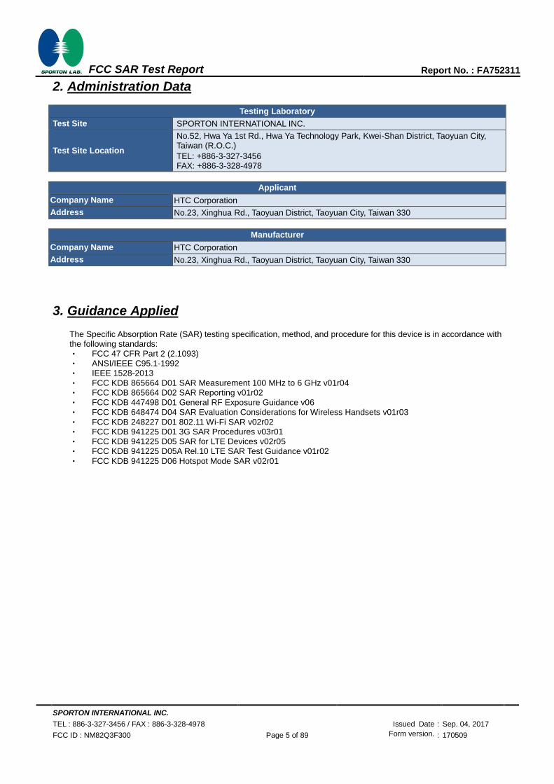
2. Administration Data
Testing Laboratory
Test Site SPORTON INTERNATIONAL INC.
Test Site Location
No.52, Hwa Ya 1st Rd., Hwa Ya Technology Park, Kwei-Shan District, Taoyuan City, Taiwan (R.O.C.)
TEL: +886-3-327-3456 FAX: +886-3-328-4978
Applicant
Company Name HTC Corporation
Address No.23, Xinghua Rd., Taoyuan District, Taoyuan City, Taiwan 330
Manufacturer
Company Name HTC Corporation
Address No.23, Xinghua Rd., Taoyuan District, Taoyuan City, Taiwan 330
3. Guidance Applied
The Specific Absorption Rate (SAR) testing specification, method, and procedure for this device is in accordance with the following standards: ‧ FCC 47 CFR Part 2 (2.1093) ‧ ANSI/IEEE C95.1-1992 ‧ IEEE 1528-2013
‧ FCC KDB 865664 D01 SAR Measurement 100 MHz to 6 GHz v01r04 ‧ FCC KDB 865664 D02 SAR Reporting v01r02 ‧ FCC KDB 447498 D01 General RF Exposure Guidance v06 ‧ FCC KDB 648474 D04 SAR Evaluation Considerations for Wireless Handsets v01r03
‧ FCC KDB 248227 D01 802.11 Wi-Fi SAR v02r02 ‧ FCC KDB 941225 D01 3G SAR Procedures v03r01 ‧ FCC KDB 941225 D05 SAR for LTE Devices v02r05 ‧ FCC KDB 941225 D05A Rel.10 LTE SAR Test Guidance v01r02
‧ FCC KDB 941225 D06 Hotspot Mode SAR v02r01
SPORTON INTERNATIONAL INC.
TEL : 886-3-327-3456 / FAX : 886-3-328-4978 Issued Date : Sep. 04, 2017
FCC ID : NM82Q3F300 Page 6 of 89 Form version. : 170509
FCC SAR Test Report Report No. : FA752311
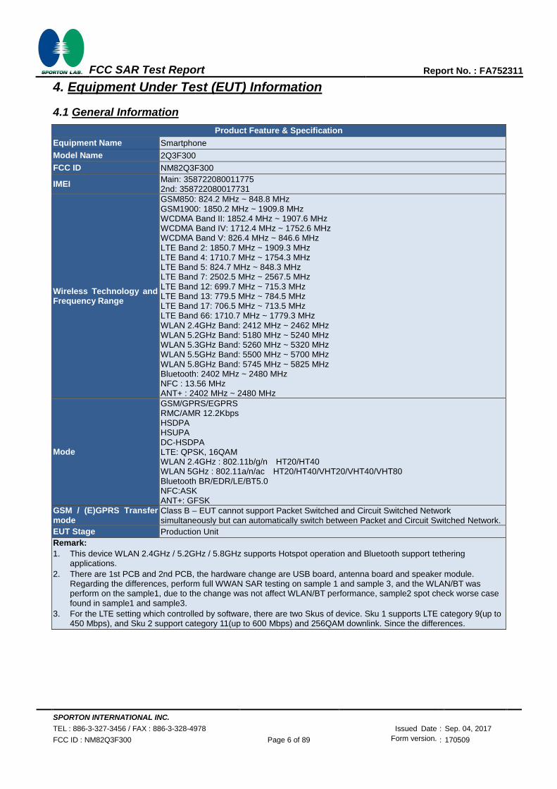
4. Equipment Under Test (EUT) Information
4.1 General Information
Product Feature & Specification
Equipment Name Smartphone
Model Name 2Q3F300
FCC ID NM82Q3F300
IMEI Main: 358722080011775 2nd: 358722080017731
Wireless Technology and Frequency Range
GSM850: 824.2 MHz ~ 848.8 MHz GSM1900: 1850.2 MHz ~ 1909.8 MHz WCDMA Band II: 1852.4 MHz ~ 1907.6 MHz WCDMA Band IV: 1712.4 MHz ~ 1752.6 MHz WCDMA Band V: 826.4 MHz ~ 846.6 MHz LTE Band 2: 1850.7 MHz ~ 1909.3 MHz LTE Band 4: 1710.7 MHz ~ 1754.3 MHz LTE Band 5: 824.7 MHz ~ 848.3 MHz LTE Band 7: 2502.5 MHz ~ 2567.5 MHz LTE Band 12: 699.7 MHz ~ 715.3 MHz LTE Band 13: 779.5 MHz ~ 784.5 MHz LTE Band 17: 706.5 MHz ~ 713.5 MHz LTE Band 66: 1710.7 MHz ~ 1779.3 MHz WLAN 2.4GHz Band: 2412 MHz ~ 2462 MHz WLAN 5.2GHz Band: 5180 MHz ~ 5240 MHz WLAN 5.3GHz Band: 5260 MHz ~ 5320 MHz WLAN 5.5GHz Band: 5500 MHz ~ 5700 MHz WLAN 5.8GHz Band: 5745 MHz ~ 5825 MHz Bluetooth: 2402 MHz ~ 2480 MHz NFC : 13.56 MHz ANT+ : 2402 MHz ~ 2480 MHz
Mode
GSM/GPRS/EGPRS RMC/AMR 12.2Kbps HSDPA HSUPA DC-HSDPA LTE: QPSK, 16QAM WLAN 2.4GHz : 802.11b/g/n HT20/HT40 WLAN 5GHz : 802.11a/n/ac HT20/HT40/VHT20/VHT40/VHT80 Bluetooth BR/EDR/LE/BT5.0 NFC:ASK ANT+: GFSK
GSM / (E)GPRS Transfer mode
Class B – EUT cannot support Packet Switched and Circuit Switched Network simultaneously but can automatically switch between Packet and Circuit Switched Network.
EUT Stage Production Unit
Remark:
1. This device WLAN 2.4GHz / 5.2GHz / 5.8GHz supports Hotspot operation and Bluetooth support tethering applications.
2. There are 1st PCB and 2nd PCB, the hardware change are USB board, antenna board and speaker module. Regarding the differences, perform full WWAN SAR testing on sample 1 and sample 3, and the WLAN/BT was perform on the sample1, due to the change was not affect WLAN/BT performance, sample2 spot check worse case found in sample1 and sample3.
3. For the LTE setting which controlled by software, there are two Skus of device. Sku 1 supports LTE category 9(up to 450 Mbps), and Sku 2 support category 11(up to 600 Mbps) and 256QAM downlink. Since the differences.

SPORTON INTERNATIONAL INC.
TEL : 886-3-327-3456 / FAX : 886-3-328-4978 Issued Date : Sep. 04, 2017
FCC ID : NM82Q3F300 Page 7 of 89 Form version. : 170509
FCC SAR Test Report Report No. : FA752311
Sample Information
Sample 1 EUT with battery 1 and 1st PCB
Sample 2 EUT with battery 2 and 1st PCB
Sample 3 EUT with battery 1 and 2nd PCB
Accessories Information
Battery 1
Brand Name HTC
Manufacturer WTE
Model Name B2Q3F100
Battery 2
Brand Name HTC
Manufacturer WTE
Model Name B2Q3F100
Earphone 1 Brand Name HTC
Model Name MAX 320

SPORTON INTERNATIONAL INC.
TEL : 886-3-327-3456 / FAX : 886-3-328-4978 Issued Date : Sep. 04, 2017
FCC ID : NM82Q3F300 Page 8 of 89 Form version. : 170509
FCC SAR Test Report Report No. : FA752311
4.2 General LTE SAR Test and Reporting Considerations
Summarized necessary items addressed in KDB 941225 D05 v02r05
FCC ID NM82Q3F300
Equipment Name Smartphone
Operating Frequency Range of each LTE transmission band
LTE Band 2: 1850.7 MHz ~ 1909.3 MHz LTE Band 4: 1710.7 MHz ~ 1754.3 MHz LTE Band 5: 824.7 MHz ~ 848.3 MHz LTE Band 7: 2502.5 MHz ~ 2567.5 MHz LTE Band 12: 699.7 MHz ~ 715.3 MHz LTE Band 13: 779.5 MHz ~ 784.5 MHz LTE Band 17: 706.5 MHz ~ 713.5 MHz LTE Band 66: 1710.7 MHz ~ 1779.3 MHz
Channel Bandwidth
LTE Band 02:1.4MHz, 3MHz, 5MHz, 10MHz, 15MHz, 20MHz LTE Band 04:1.4MHz, 3MHz, 5MHz, 10MHz, 15MHz, 20MHz LTE Band 05:1.4MHz, 3MHz, 5MHz, 10MHz LTE Band 07: 5MHz, 10MHz, 15MHz, 20MHz LTE Band 12:1.4MHz, 3MHz, 5MHz, 10MHz LTE Band 13: 5MHz, 10MHz LTE Band 17: 5MHz, 10MHz LTE Band 66:1.4MHz, 3MHz, 5MHz, 10MHz, 15MHz, 20MHz
uplink modulations used QPSK / 16QAM
LTE Voice / Data requirements Voice and Data
LTE MPR permanently built-in by design
LTE A-MPR In the base station simulator configuration, Network Setting value is set to NS_01 to disable A-MPR during SAR testing and the LTE SAR tests was transmitting on all TTI frames (Maximum TTI)
Spectrum plots for RB configuration A properly configured base station simulator was used for the SAR and power measurement; therefore, spectrum plots for each RB allocation and offset configuration are not included in the SAR report.
LTE Carrier Aggregation Combinations Inter-Band and Intra-Band possible combinations as below page and the detail power verification please refer to section 12.
LTE Carrier Aggregation Additional Information
This device does not support full CA features on 3GPP Release 11. It supports a maximum of 2 carriers in the downlink only. All uplink communications are identical to the Release 8 Specifications. Uplink communications are done on the PCC. The following LTE Release features are not supported: Relay, HetNet, Enhanced MIMO, eICI, WiFi Offloading, MDH, eMBMA, Cross-Carrier Scheduling, Enhanced SC-FDMA.

SPORTON INTERNATIONAL INC.
TEL : 886-3-327-3456 / FAX : 886-3-328-4978 Issued Date : Sep. 04, 2017
FCC ID : NM82Q3F300 Page 9 of 89 Form version. : 170509
FCC SAR Test Report Report No. : FA752311
Transmission (H, M, L) channel numbers and frequencies in each LTE band
LTE Band 2
Bandwidth 1.4 MHz Bandwidth 3 MHz Bandwidth 5 MHz Bandwidth 10 MHz Bandwidth 15 MHz Bandwidth 20 MHz
Ch. # Freq. (MHz)
Ch. # Freq. (MHz)
Ch. # Freq. (MHz)
Ch. # Freq. (MHz)
Ch. # Freq. (MHz)
Ch. # Freq. (MHz)
L 18607 1850.7 18615 1851.5 18625 1852.5 18650 1855 18675 1857.5 18700 1860
M 18900 1880 18900 1880 18900 1880 18900 1880 18900 1880 18900 1880
H 19193 1909.3 19185 1908.5 19175 1907.5 19150 1905 19125 1902.5 19100 1900
LTE Band 4
Bandwidth 1.4 MHz Bandwidth 3 MHz Bandwidth 5 MHz Bandwidth 10 MHz Bandwidth 15 MHz Bandwidth 20 MHz
Ch. # Freq. (MHz)
Ch. # Freq. (MHz)
Ch. # Freq. (MHz)
Ch. # Freq. (MHz)
Ch. # Freq. (MHz)
Ch. # Freq. (MHz)
L 19957 1710.7 19965 1711.5 19975 1712.5 20000 1715 20025 1717.5 20050 1720
M 20175 1732.5 20175 1732.5 20175 1732.5 20175 1732.5 20175 1732.5 20175 1732.5
H 20393 1754.3 20385 1753.5 20375 1752.5 20350 1750 20325 1747.5 20300 1745
LTE Band 5
Bandwidth 1.4 MHz Bandwidth 3 MHz Bandwidth 5 MHz Bandwidth 10 MHz
Ch. # Freq. (MHz) Ch. # Freq. (MHz) Ch. # Freq. (MHz) Ch. # Freq. (MHz)
L 20407 824.7 20415 825.5 20425 826.5 20450 829
M 20525 836.5 20525 836.5 20525 836.5 20525 836.5
H 20643 848.3 20635 847.5 20625 846.5 20600 844
LTE Band 7
Bandwidth 5 MHz Bandwidth 10 MHz Bandwidth 15 MHz Bandwidth 20 MHz
Ch. # Freq. (MHz) Ch. # Freq. (MHz) Ch. # Freq. (MHz) Ch. # Freq. (MHz)
L 20775 2502.5 20800 2505 20825 2507.5 20850 2510
M 21100 2535 21100 2535 21100 2535 21100 2535
H 21425 2567.5 21400 2565 21375 2562.5 21350 2560
LTE Band 12
Bandwidth 1.4 MHz Bandwidth 3 MHz Bandwidth 5 MHz Bandwidth 10 MHz
Ch. # Freq. (MHz) Ch. # Freq. (MHz) Ch. # Freq. (MHz) Ch. # Freq. (MHz)
L 23017 699.7 23025 700.5 23035 701.5 23060 704
M 23095 707.5 23095 707.5 23095 707.5 23095 707.5
H 23173 715.3 23165 714.5 23155 713.5 23130 711
LTE Band 13
Bandwidth 5 MHz Bandwidth 10 MHz
Channel # Freq.(MHz) Channel # Freq.(MHz)
L 23205 779.5
23230 782 M 23230 782
H 23255 784.5
LTE Band 17
Bandwidth 5 MHz Bandwidth 10 MHz
Channel # Freq.(MHz) Channel # Freq. (MHz)
L 23755 706.5 23780 709
M 23790 710 23790 710
H 23825 713.5 23800 711
LTE Band 66
Bandwidth 1.4 MHz Bandwidth 3 MHz Bandwidth 5 MHz Bandwidth 10 MHz Bandwidth 15 MHz Bandwidth 20 MHz
Ch. # Freq. (MHz)
Ch. # Freq. (MHz)
Ch. # Freq. (MHz)
Ch. # Freq. (MHz)
Ch. # Freq. (MHz)
Ch. # Freq. (MHz)
L 131979 1710.7 131987 1711.5 131997 1712.5 132022 1715 132047 1717.5 132072 1720
M 132322 1745 132322 1745 132322 1745 132322 1745 132322 1745 132322 1745
H 132665 1779.3 132657 1778.5 132647 1777.5 132622 1775 132597 1772.5 132572 1770
SPORTON INTERNATIONAL INC.
TEL : 886-3-327-3456 / FAX : 886-3-328-4978 Issued Date : Sep. 04, 2017
FCC ID : NM82Q3F300 Page 10 of 89 Form version. : 170509
FCC SAR Test Report Report No. : FA752311
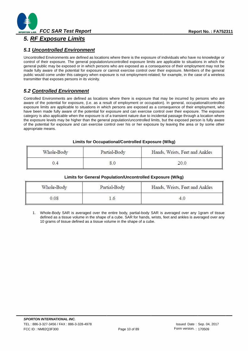
5. RF Exposure Limits
5.1 Uncontrolled Environment
Uncontrolled Environments are defined as locations where there is the exposure of individuals who have no knowledge or control of their exposure. The general population/uncontrolled exposure limits are applicable to situations in which the general public may be exposed or in which persons who are exposed as a consequence of their employment may not be made fully aware of the potential for exposure or cannot exercise control over their exposure. Members of the general public would come under this category when exposure is not employment-related; for example, in the case of a wireless transmitter that exposes persons in its vicinity.
5.2 Controlled Environment
Controlled Environments are defined as locations where there is exposure that may be incurred by persons who are aware of the potential for exposure, (i.e. as a result of employment or occupation). In general, occupational/controlled exposure limits are applicable to situations in which persons are exposed as a consequence of their employment, who have been made fully aware of the potential for exposure and can exercise control over their exposure. The exposure category is also applicable when the exposure is of a transient nature due to incidental passage through a location where the exposure levels may be higher than the general population/uncontrolled limits, but the exposed person is fully aware of the potential for exposure and can exercise control over his or her exposure by leaving the area or by some other appropriate means.
Limits for Occupational/Controlled Exposure (W/kg)
Limits for General Population/Uncontrolled Exposure (W/kg)
1. Whole-Body SAR is averaged over the entire body, partial-body SAR is averaged over any 1gram of tissue
defined as a tissue volume in the shape of a cube. SAR for hands, wrists, feet and ankles is averaged over any 10 grams of tissue defined as a tissue volume in the shape of a cube.

SPORTON INTERNATIONAL INC.
TEL : 886-3-327-3456 / FAX : 886-3-328-4978 Issued Date : Sep. 04, 2017
FCC ID : NM82Q3F300 Page 11 of 89 Form version. : 170509
FCC SAR Test Report Report No. : FA752311
6. Specific Absorption Rate (SAR)
6.1 Introduction
SAR is related to the rate at which energy is absorbed per unit mass in an object exposed to a radio field. The SAR distribution in a biological body is complicated and is usually carried out by experimental techniques or numerical modeling. The standard recommends limits for two tiers of groups, occupational/controlled and general population/uncontrolled, based on a person’s awareness and ability to exercise control over his or her exposure. In general, occupational/controlled exposure limits are higher than the limits for general population/uncontrolled.
6.2 SAR Definition
The SAR definition is the time derivative (rate) of the incremental energy (dW) absorbed by (dissipated in) an incremental mass (dm) contained in a volume element (dv) of a given density (ρ). The equation description is as below:
𝐒𝐀𝐑 =𝐝
𝐝𝐭(𝐝𝐖
𝐝𝐦) =
𝐝
𝐝𝐭(𝐝𝐖
𝛒𝐝𝐯)
SAR is expressed in units of Watts per kilogram (W/kg)
𝐒𝐀𝐑 =𝛔|𝐄|𝟐
𝛒
Where: σ is the conductivity of the tissue, ρ is the mass density of the tissue and E is the RMS electrical field strength.

SPORTON INTERNATIONAL INC.
TEL : 886-3-327-3456 / FAX : 886-3-328-4978 Issued Date : Sep. 04, 2017
FCC ID : NM82Q3F300 Page 12 of 89 Form version. : 170509
FCC SAR Test Report Report No. : FA752311
7. System Description and Setup
The DASY system used for performing compliance tests consists of the following items:
A standard high precision 6-axis robot with controller, teach pendant and software. An arm extension for
accommodating the data acquisition electronics (DAE).
An isotropic Field probe optimized and calibrated for the targeted measurement.
A data acquisition electronics (DAE) which performs the signal amplification, signal multiplexing, AD-conversion, offset measurements, mechanical surface detection, collision detection, etc. The unit is battery powered with standard or rechargeable batteries. The signal is optically transmitted to the EOC.
The Electro-optical converter (EOC) performs the conversion from optical to electrical signals for the digital communication to the DAE. To use optical surface detection, a special version of the EOC is required. The EOC signal is transmitted to the measurement server.
The function of the measurement server is to perform the time critical tasks such as signal filtering, control of the robot operation and fast movement interrupts.
The Light Beam used is for probe alignment. This improves the (absolute) accuracy of the probe positioning.
A computer running WinXP or Win7 and the DASY5 software.
Remote control and teach pendant as well as additional circuitry for robot safety such as warning lamps, etc.
The phantom, the device holder and other accessories according to the targeted measurement.

SPORTON INTERNATIONAL INC.
TEL : 886-3-327-3456 / FAX : 886-3-328-4978 Issued Date : Sep. 04, 2017
FCC ID : NM82Q3F300 Page 13 of 89 Form version. : 170509
FCC SAR Test Report Report No. : FA752311
7.1 E-Field Probe
The SAR measurement is conducted with the dosimetric probe (manufactured by SPEAG).The probe is specially designed and calibrated for use in liquid with high permittivity. The dosimetric probe has special calibration in liquid at different frequency. This probe has a built in optical surface detection system to prevent from collision with phantom.
<ES3DV3 Probe> Construction Symmetric design with triangular core
Interleaved sensors Built-in shielding against static charges PEEK enclosure material (resistant to organic solvents, e.g., DGBE)
Frequency 10 MHz – 4 GHz; Linearity: ±0.2 dB (30 MHz – 4 GHz)
Directivity ±0.2 dB in TSL (rotation around probe axis)
±0.3 dB in TSL (rotation normal to probe axis)
Dynamic Range 5 µW/g – >100 mW/g; Linearity: ±0.2 dB
Dimensions Overall length: 337 mm (tip: 20 mm) Tip diameter: 3.9 mm (body: 12 mm) Distance from probe tip to dipole centers: 3.0 mm
<EX3DV4 Probe> Construction Symmetric design with triangular core
Built-in shielding against static charges PEEK enclosure material (resistant to organic solvents, e.g., DGBE)
Frequency 10 MHz – >6 GHz Linearity: ±0.2 dB (30 MHz – 6 GHz)
Directivity ±0.3 dB in TSL (rotation around probe axis)
±0.5 dB in TSL (rotation normal to probe axis)
Dynamic Range 10 µW/g – >100 mW/g Linearity: ±0.2 dB (noise: typically <1 µW/g)
Dimensions Overall length: 337 mm (tip: 20 mm) Tip diameter: 2.5 mm (body: 12 mm) Typical distance from probe tip to dipole centers: 1 mm
7.2 Data Acquisition Electronics (DAE)
The data acquisition electronics (DAE) consists of a highly sensitive
electrometer-grade preamplifier with auto-zeroing, a channel and
gain-switching multiplexer, a fast 16 bit AD-converter and a command
decoder and control logic unit. Transmission to the measurement server is
accomplished through an optical downlink for data and status information as
well as an optical uplink for commands and the clock.
The input impedance of the DAE is 200 MOhm; the inputs are symmetrical
and floating. Common mode rejection is above 80 dB.
Fig 5.1 Photo of DAE

SPORTON INTERNATIONAL INC.
TEL : 886-3-327-3456 / FAX : 886-3-328-4978 Issued Date : Sep. 04, 2017
FCC ID : NM82Q3F300 Page 14 of 89 Form version. : 170509
FCC SAR Test Report Report No. : FA752311
7.3 Phantom
<SAM Twin Phantom>
Shell Thickness 2 ± 0.2 mm;
Center ear point: 6 ± 0.2 mm
Filling Volume Approx. 25 liters
Dimensions Length: 1000 mm; Width: 500 mm; Height:
adjustable feet
Measurement Areas Left Hand, Right Hand, Flat Phantom
The bottom plate contains three pair of bolts for locking the device holder. The device holder positions are adjusted to the standard measurement positions in the three sections. A white cover is provided to tap the phantom during off-periods to prevent water evaporation and changes in the liquid parameters. On the phantom top, three reference markers are provided to identify the phantom position with respect to the robot.
<ELI Phantom>
Shell Thickness 2 ± 0.2 mm (sagging: <1%)
Filling Volume Approx. 30 liters
Dimensions Major ellipse axis: 600 mm
Minor axis: 400 mm
The ELI phantom is intended for compliance testing of handheld and body-mounted wireless devices in the frequency range of 30 MHz to 6 GHz. ELI4 is fully compatible with standard and all known tissue simulating liquids.
SPORTON INTERNATIONAL INC.
TEL : 886-3-327-3456 / FAX : 886-3-328-4978 Issued Date : Sep. 04, 2017
FCC ID : NM82Q3F300 Page 15 of 89 Form version. : 170509
FCC SAR Test Report Report No. : FA752311
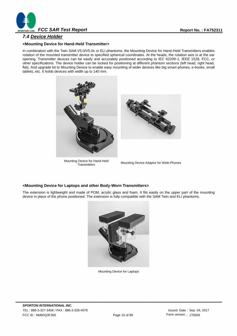
7.4 Device Holder
<Mounting Device for Hand-Held Transmitter>
In combination with the Twin SAM V5.0/V5.0c or ELI phantoms, the Mounting Device for Hand-Held Transmitters enables rotation of the mounted transmitter device to specified spherical coordinates. At the heads, the rotation axis is at the ear opening. Transmitter devices can be easily and accurately positioned according to IEC 62209-1, IEEE 1528, FCC, or other specifications. The device holder can be locked for positioning at different phantom sections (left head, right head, flat). And upgrade kit to Mounting Device to enable easy mounting of wider devices like big smart-phones, e-books, small tablets, etc. It holds devices with width up to 140 mm.
Mounting Device for Hand-Held Transmitters
Mounting Device Adaptor for Wide-Phones
<Mounting Device for Laptops and other Body-Worn Transmitters>
The extension is lightweight and made of POM, acrylic glass and foam. It fits easily on the upper part of the mounting device in place of the phone positioned. The extension is fully compatible with the SAM Twin and ELI phantoms.
Mounting Device for Laptops

SPORTON INTERNATIONAL INC.
TEL : 886-3-327-3456 / FAX : 886-3-328-4978 Issued Date : Sep. 04, 2017
FCC ID : NM82Q3F300 Page 16 of 89 Form version. : 170509
FCC SAR Test Report Report No. : FA752311
8. Measurement Procedures
The measurement procedures are as follows:
<Conducted power measurement>
(a) For WWAN power measurement, use base station simulator to configure EUT WWAN transmission in conducted connection with RF cable, at maximum power in each supported wireless interface and frequency band.
(b) Read the WWAN RF power level from the base station simulator. (c) For WLAN/BT power measurement, use engineering software to configure EUT WLAN/BT continuously
transmission, at maximum RF power in each supported wireless interface and frequency band (d) Connect EUT RF port through RF cable to the power meter, and measure WLAN/BT output power
<SAR measurement>
(a) Use base station simulator to configure EUT WWAN transmission in radiated connection, and engineering software to configure EUT WLAN/BT continuously transmission, at maximum RF power, in the highest power channel.
(b) Place the EUT in the positions as Appendix D demonstrates. (c) Set scan area, grid size and other setting on the DASY software. (d) Measure SAR results for the highest power channel on each testing position. (e) Find out the largest SAR result on these testing positions of each band (f) Measure SAR results for other channels in worst SAR testing position if the reported SAR of highest power
channel is larger than 0.8 W/kg
According to the test standard, the recommended procedure for assessing the peak spatial-average SAR value consists of the following steps:
(a) Power reference measurement (b) Area scan (c) Zoom scan (d) Power drift measurement
8.1 Spatial Peak SAR Evaluation
The procedure for spatial peak SAR evaluation has been implemented according to the test standard. It can be conducted for 1g and 10g, as well as for user-specific masses. The DASY software includes all numerical procedures necessary to evaluate the spatial peak SAR value.
The base for the evaluation is a "cube" measurement. The measured volume must include the 1g and 10g cubes with the highest averaged SAR values. For that purpose, the center of the measured volume is aligned to the interpolated peak SAR value of a previously performed area scan.
The entire evaluation of the spatial peak values is performed within the post-processing engine (SEMCAD). The system always gives the maximum values for the 1g and 10g cubes. The algorithm to find the cube with highest averaged SAR is divided into the following stages:
(a) Extraction of the measured data (grid and values) from the Zoom Scan (b) Calculation of the SAR value at every measurement point based on all stored data (A/D values and
measurement parameters) (c) Generation of a high-resolution mesh within the measured volume (d) Interpolation of all measured values form the measurement grid to the high-resolution grid (e) Extrapolation of the entire 3-D field distribution to the phantom surface over the distance from sensor to surface (f) Calculation of the averaged SAR within masses of 1g and 10g

SPORTON INTERNATIONAL INC.
TEL : 886-3-327-3456 / FAX : 886-3-328-4978 Issued Date : Sep. 04, 2017
FCC ID : NM82Q3F300 Page 17 of 89 Form version. : 170509
FCC SAR Test Report Report No. : FA752311
8.2 Power Reference Measurement
The Power Reference Measurement and Power Drift Measurements are for monitoring the power drift of the device under test in the batch process. The minimum distance of probe sensors to surface determines the closest measurement point to phantom surface. This distance cannot be smaller than the distance of sensor calibration points to probe tip as defined in the probe properties.
8.3 Area Scan
The area scan is used as a fast scan in two dimensions to find the area of high field values, before doing a fine measurement around the hot spot. The sophisticated interpolation routines implemented in DASY software can find the maximum found in the scanned area, within a range of the global maximum. The range (in dB0 is specified in the standards for compliance testing. For example, a 2 dB range is required in IEEE standard 1528 and IEC 62209 standards, whereby 3 dB is a requirement when compliance is assessed in accordance with the ARIB standard (Japan), if only one zoom scan follows the area scan, then only the absolute maximum will be taken as reference. For cases where multiple maximums are detected, the number of zoom scans has to be increased accordingly.
Area scan parameters extracted from FCC KDB 865664 D01v01r04 SAR measurement 100 MHz to 6 GHz.

SPORTON INTERNATIONAL INC.
TEL : 886-3-327-3456 / FAX : 886-3-328-4978 Issued Date : Sep. 04, 2017
FCC ID : NM82Q3F300 Page 18 of 89 Form version. : 170509
FCC SAR Test Report Report No. : FA752311
8.4 Zoom Scan
Zoom scans are used assess the peak spatial SAR values within a cubic averaging volume containing 1 gram and 10 gram of simulated tissue. The zoom scan measures points (refer to table below) within a cube shoes base faces are centered on the maxima found in a preceding area scan job within the same procedure. When the measurement is done, the zoom scan evaluates the averaged SAR for 1 gram and 10 gram and displays these values next to the job’s label.
Zoom scan parameters extracted from FCC KDB 865664 D01v01r04 SAR measurement 100 MHz to 6 GHz.
8.5 Volume Scan Procedures
The volume scan is used for assess overlapping SAR distributions for antennas transmitting in different frequency bands. It is equivalent to an oversized zoom scan used in standalone measurements. The measurement volume will be used to enclose all the simultaneous transmitting antennas. For antennas transmitting simultaneously in different frequency bands, the volume scan is measured separately in each frequency band. In order to sum correctly to compute the 1g aggregate SAR, the EUT remain in the same test position for all measurements and all volume scan use the same spatial resolution and grid spacing. When all volume scan were completed, the software, SEMCAD postprocessor can combine and subsequently superpose these measurement data to calculating the multiband SAR.
8.6 Power Drift Monitoring
All SAR testing is under the EUT install full charged battery and transmit maximum output power. In DASY measurement
software, the power reference measurement and power drift measurement procedures are used for monitoring the power
drift of EUT during SAR test. Both these procedures measure the field at a specified reference position before and after
the SAR testing. The software will calculate the field difference in dB. If the power drifts more than 5%, the SAR will be
retested.

SPORTON INTERNATIONAL INC.
TEL : 886-3-327-3456 / FAX : 886-3-328-4978 Issued Date : Sep. 04, 2017
FCC ID : NM82Q3F300 Page 19 of 89 Form version. : 170509
FCC SAR Test Report Report No. : FA752311
9. Test Equipment List
Manufacturer Name of Equipment Type/Model Serial Number Calibration
Last Cal. Due Date
SPEAG 750MHz System Validation Kit D750V3 1012 May. 22, 2017 May. 21, 2018
SPEAG 835MHz System Validation Kit D835V2 499 Mar. 21, 2017 Mar. 20, 2018
SPEAG 1750MHz System Validation Kit D1750V2 1068 Nov. 16, 2016 Nov. 15, 2017
SPEAG 1900MHz System Validation Kit D1900V2 5d041 Sep. 30, 2016 Sep. 29, 2017
SPEAG 2450MHz System Validation Kit D2450V2 926 Jul. 25, 2016 Jul. 24, 2017
SPEAG 2600MHz System Validation Kit D2600V2 1008 Aug. 30, 2016 Aug. 29, 2017
SPEAG 2600MHz System Validation Kit D2600V2 1113 Aug. 30, 2016 Aug. 29, 2017
SPEAG 5GHz System Validation Kit D5GHzV2 1006 Sep. 27, 2016 Sep. 26, 2017
SPEAG Data Acquisition Electronics DAE3 495 May. 22, 2017 May. 21, 2018
SPEAG Data Acquisition Electronics DAE4 916 Dec. 15, 2016 Dec. 14, 2017
SPEAG Data Acquisition Electronics DAE4 1399 Nov. 17, 2016 Nov. 16, 2017
SPEAG Data Acquisition Electronics DAE4 778 May. 22, 2017 May. 21, 2018
SPEAG Data Acquisition Electronics DAE4 1424 Feb. 16, 2017 Feb. 15, 2018
SPEAG Data Acquisition Electronics DAE4 854 May. 02, 2017 May. 01, 2018
SPEAG Dosimetric E-Field Probe EX3DV4 3976 Feb. 21, 2017 Feb. 20, 2018
SPEAG Dosimetric E-Field Probe EX3DV4 7306 Jul. 24, 2017 Jul. 23, 2018
SPEAG Dosimetric E-Field Probe EX3DV4 3925 May. 24, 2017 May. 23, 2018
SPEAG Dosimetric E-Field Probe ES3DV3 3270 Aug. 26, 2016 Aug. 25, 2017
SPEAG Dosimetric E-Field Probe ES3DV3 3169 May. 11, 2017 May. 10, 2018
WonDer Thermometer WD-5016 TM560-1 Mar. 17, 2017 Mar. 16, 2018
WonDer Thermometer WD-5016 TM560-2 Mar. 17, 2017 Mar. 16, 2018
TECPEL Thermometer UL-A03 TM225-1 Mar. 21, 2017 Mar. 20, 2018
WonDer Thermometer WD-5016 TM281-2 Mar. 17, 2017 Mar. 16, 2018
WonDer Thermometer WD-5016 TM281-1 Mar. 17, 2017 Mar. 16, 2018
Anritsu Radio Communication Analyzer MT8821C 6201341950 Apr. 20, 2017 Apr. 19, 2018
Agilent Wireless Communication Test Set E5515C GB46311322 Mar. 13, 2017 Mar. 12, 2018
R&S BT Base Station CBT32 100522 Mar. 14, 2017 Mar. 13, 2018
SPEAG Device Holder N/A N/A N/A N/A
Anritsu Signal Generator MG3710A 6201502524 Dec. 09, 2016 Dec. 08, 2017
Agilent ENA Network Analyzer E5071C MY46316648 Jan. 04, 2017 Jan. 03, 2018
SPEAG Dielectric Probe Kit DAK-3.5 1126 Jul. 19, 2016 Jul. 18, 2017
SPEAG Dielectric Probe Kit DAK-3.5 1146 Jul. 18, 2017 Jul. 17, 2018
LINE SEIKI Digital Thermometer LKMelectronic DTM3000SPEZIAL Sep. 05, 2016 Sep. 04, 2017
Anritsu Power Meter ML2495A 1438002 Dec. 06, 2016 Dec. 05, 2017
Anritsu Power Sensor MA2411B 1339195 Dec. 06, 2016 Dec. 05, 2017
Agilent Spectrum Analyzer E4408B MY44211028 Aug. 22, 2016 Aug. 21, 2017
Anritsu Spectrum Analyzer MS2830A 6201396378 Jun. 26, 2017 Jun. 25, 2018
Mini-Circuits Power Amplifier ZVE-8G+ D120604 Mar. 09, 2017 Mar. 08, 2018
Mini-Circuits Power Amplifier ZHL-42W+ QA1344002 Mar. 09, 2017 Mar. 08, 2018
ATM Dual Directional Coupler C122H-10 P610410z-02 Note 1
Woken Attenuator 1 WK0602-XX N/A Note 1
PE Attenuator 2 PE7005-10 N/A Note 1
PE Attenuator 3 PE7005- 3 N/A Note 1
General Note:
1. Prior to system verification and validation, the path loss from the signal generator to the system check source and the power meter, which includes the amplifier, cable, attenuator and directional coupler, was measured by the network analyzer. The reading of the power meter was offset by the path loss difference between the path to the power meter and the path to the system check source to monitor the actual power level fed to the system check source.

SPORTON INTERNATIONAL INC.
TEL : 886-3-327-3456 / FAX : 886-3-328-4978 Issued Date : Sep. 04, 2017
FCC ID : NM82Q3F300 Page 20 of 89 Form version. : 170509
FCC SAR Test Report Report No. : FA752311
10. System Verification
10.1 Tissue Simulating Liquids
For the measurement of the field distribution inside the SAM phantom with DASY, the phantom must be
filled with around 25 liters of homogeneous body tissue simulating liquid. For head SAR testing, the liquid
height from the ear reference point (ERP) of the phantom to the liquid top surface is larger than 15 cm,
which is shown in Fig. 10.1. For body SAR testing, the liquid height from the center of the flat phantom to
the liquid top surface is larger than 15 cm, which is shown in Fig. 10.2.
Fig 10.1Photo of Liquid Height for Head SAR Fig 10.2 Photo of Liquid Height for Body SAR

SPORTON INTERNATIONAL INC.
TEL : 886-3-327-3456 / FAX : 886-3-328-4978 Issued Date : Sep. 04, 2017
FCC ID : NM82Q3F300 Page 21 of 89 Form version. : 170509
FCC SAR Test Report Report No. : FA752311
10.2 Tissue Verification
The following tissue formulations are provided for reference only as some of the parameters have not been thoroughly verified. The composition of ingredients may be modified accordingly to achieve the desired target tissue parameters required for routine SAR evaluation.
Frequency (MHz)
Water (%)
Sugar (%)
Cellulose (%)
Salt (%)
Preventol (%)
DGBE (%)
Conductivity (σ)
Permittivity (εr)
For Head
750 41.1 57.0 0.2 1.4 0.2 0 0.89 41.9
835 40.3 57.9 0.2 1.4 0.2 0 0.90 41.5
900 40.3 57.9 0.2 1.4 0.2 0 0.97 41.5
1800, 1900, 2000 55.2 0 0 0.3 0 44.5 1.40 40.0
2450 55.0 0 0 0 0 45.0 1.80 39.2
2600 54.8 0 0 0.1 0 45.1 1.96 39.0
For Body
750 51.7 47.2 0 0.9 0.1 0 0.96 55.5
835 50.8 48.2 0 0.9 0.1 0 0.97 55.2
900 50.8 48.2 0 0.9 0.1 0 1.05 55.0
1800, 1900, 2000 70.2 0 0 0.4 0 29.4 1.52 53.3
2450 68.6 0 0 0 0 31.4 1.95 52.7
2600 68.1 0 0 0.1 0 31.8 2.16 52.5
Simulating Liquid for 5GHz, Manufactured by SPEAG Ingredients (% by weight)
Water 64~78%
Mineral oil 11~18%
Emulsifiers 9~15%
Additives and Salt 2~3%
SPORTON INTERNATIONAL INC.
TEL : 886-3-327-3456 / FAX : 886-3-328-4978 Issued Date : Sep. 04, 2017
FCC ID : NM82Q3F300 Page 22 of 89 Form version. : 170509
FCC SAR Test Report Report No. : FA752311
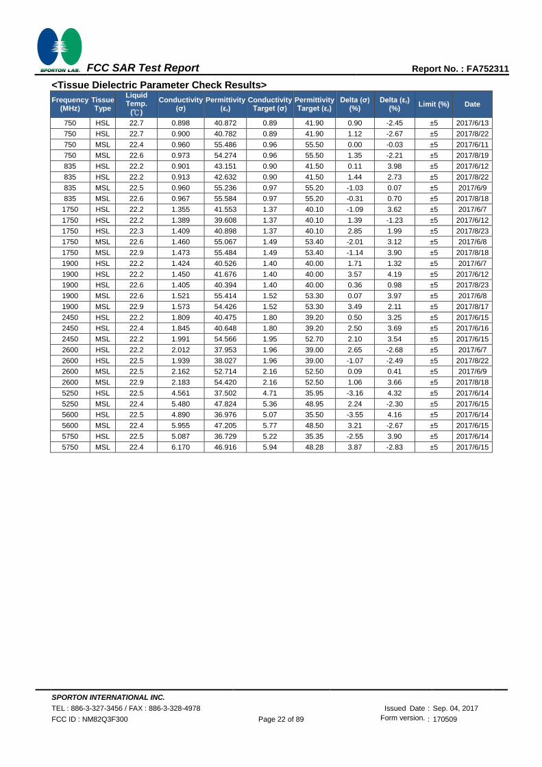
<Tissue Dielectric Parameter Check Results>
Frequency (MHz)
Tissue Type
Liquid Temp.
()
Conductivity (σ)
Permittivity (εr)
Conductivity Target (σ)
Permittivity Target (εr)
Delta (σ) (%)
Delta (εr) (%)
Limit (%) Date
750 HSL 22.7 0.898 40.872 0.89 41.90 0.90 -2.45 ±5 2017/6/13
750 HSL 22.7 0.900 40.782 0.89 41.90 1.12 -2.67 ±5 2017/8/22
750 MSL 22.4 0.960 55.486 0.96 55.50 0.00 -0.03 ±5 2017/6/11
750 MSL 22.6 0.973 54.274 0.96 55.50 1.35 -2.21 ±5 2017/8/19
835 HSL 22.2 0.901 43.151 0.90 41.50 0.11 3.98 ±5 2017/6/12
835 HSL 22.2 0.913 42.632 0.90 41.50 1.44 2.73 ±5 2017/8/22
835 MSL 22.5 0.960 55.236 0.97 55.20 -1.03 0.07 ±5 2017/6/9
835 MSL 22.6 0.967 55.584 0.97 55.20 -0.31 0.70 ±5 2017/8/18
1750 HSL 22.2 1.355 41.553 1.37 40.10 -1.09 3.62 ±5 2017/6/7
1750 HSL 22.2 1.389 39.608 1.37 40.10 1.39 -1.23 ±5 2017/6/12
1750 HSL 22.3 1.409 40.898 1.37 40.10 2.85 1.99 ±5 2017/8/23
1750 MSL 22.6 1.460 55.067 1.49 53.40 -2.01 3.12 ±5 2017/6/8
1750 MSL 22.9 1.473 55.484 1.49 53.40 -1.14 3.90 ±5 2017/8/18
1900 HSL 22.2 1.424 40.526 1.40 40.00 1.71 1.32 ±5 2017/6/7
1900 HSL 22.2 1.450 41.676 1.40 40.00 3.57 4.19 ±5 2017/6/12
1900 HSL 22.6 1.405 40.394 1.40 40.00 0.36 0.98 ±5 2017/8/23
1900 MSL 22.6 1.521 55.414 1.52 53.30 0.07 3.97 ±5 2017/6/8
1900 MSL 22.9 1.573 54.426 1.52 53.30 3.49 2.11 ±5 2017/8/17
2450 HSL 22.2 1.809 40.475 1.80 39.20 0.50 3.25 ±5 2017/6/15
2450 HSL 22.4 1.845 40.648 1.80 39.20 2.50 3.69 ±5 2017/6/16
2450 MSL 22.2 1.991 54.566 1.95 52.70 2.10 3.54 ±5 2017/6/15
2600 HSL 22.2 2.012 37.953 1.96 39.00 2.65 -2.68 ±5 2017/6/7
2600 HSL 22.5 1.939 38.027 1.96 39.00 -1.07 -2.49 ±5 2017/8/22
2600 MSL 22.5 2.162 52.714 2.16 52.50 0.09 0.41 ±5 2017/6/9
2600 MSL 22.9 2.183 54.420 2.16 52.50 1.06 3.66 ±5 2017/8/18
5250 HSL 22.5 4.561 37.502 4.71 35.95 -3.16 4.32 ±5 2017/6/14
5250 MSL 22.4 5.480 47.824 5.36 48.95 2.24 -2.30 ±5 2017/6/15
5600 HSL 22.5 4.890 36.976 5.07 35.50 -3.55 4.16 ±5 2017/6/14
5600 MSL 22.4 5.955 47.205 5.77 48.50 3.21 -2.67 ±5 2017/6/15
5750 HSL 22.5 5.087 36.729 5.22 35.35 -2.55 3.90 ±5 2017/6/14
5750 MSL 22.4 6.170 46.916 5.94 48.28 3.87 -2.83 ±5 2017/6/15
SPORTON INTERNATIONAL INC.
TEL : 886-3-327-3456 / FAX : 886-3-328-4978 Issued Date : Sep. 04, 2017
FCC ID : NM82Q3F300 Page 23 of 89 Form version. : 170509
FCC SAR Test Report Report No. : FA752311
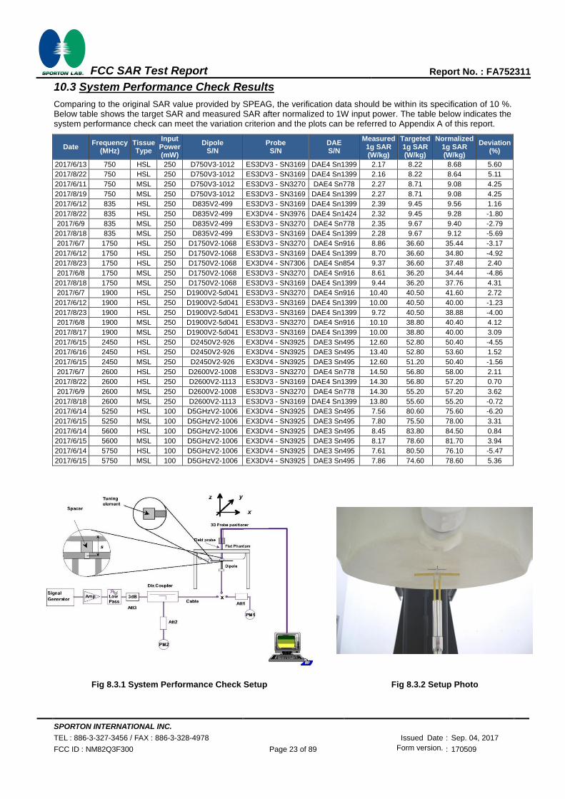
10.3 System Performance Check Results
Comparing to the original SAR value provided by SPEAG, the verification data should be within its specification of 10 %. Below table shows the target SAR and measured SAR after normalized to 1W input power. The table below indicates the system performance check can meet the variation criterion and the plots can be referred to Appendix A of this report.
Date Frequency
(MHz) Tissue Type
Input Power (mW)
Dipole S/N
Probe S/N
DAE S/N
Measured 1g SAR (W/kg)
Targeted 1g SAR (W/kg)
Normalized 1g SAR (W/kg)
Deviation (%)
2017/6/13 750 HSL 250 D750V3-1012 ES3DV3 - SN3169 DAE4 Sn1399 2.17 8.22 8.68 5.60
2017/8/22 750 HSL 250 D750V3-1012 ES3DV3 - SN3169 DAE4 Sn1399 2.16 8.22 8.64 5.11
2017/6/11 750 MSL 250 D750V3-1012 ES3DV3 - SN3270 DAE4 Sn778 2.27 8.71 9.08 4.25
2017/8/19 750 MSL 250 D750V3-1012 ES3DV3 - SN3169 DAE4 Sn1399 2.27 8.71 9.08 4.25
2017/6/12 835 HSL 250 D835V2-499 ES3DV3 - SN3169 DAE4 Sn1399 2.39 9.45 9.56 1.16
2017/8/22 835 HSL 250 D835V2-499 EX3DV4 - SN3976 DAE4 Sn1424 2.32 9.45 9.28 -1.80
2017/6/9 835 MSL 250 D835V2-499 ES3DV3 - SN3270 DAE4 Sn778 2.35 9.67 9.40 -2.79
2017/8/18 835 MSL 250 D835V2-499 ES3DV3 - SN3169 DAE4 Sn1399 2.28 9.67 9.12 -5.69
2017/6/7 1750 HSL 250 D1750V2-1068 ES3DV3 - SN3270 DAE4 Sn916 8.86 36.60 35.44 -3.17
2017/6/12 1750 HSL 250 D1750V2-1068 ES3DV3 - SN3169 DAE4 Sn1399 8.70 36.60 34.80 -4.92
2017/8/23 1750 HSL 250 D1750V2-1068 EX3DV4 - SN7306 DAE4 Sn854 9.37 36.60 37.48 2.40
2017/6/8 1750 MSL 250 D1750V2-1068 ES3DV3 - SN3270 DAE4 Sn916 8.61 36.20 34.44 -4.86
2017/8/18 1750 MSL 250 D1750V2-1068 ES3DV3 - SN3169 DAE4 Sn1399 9.44 36.20 37.76 4.31
2017/6/7 1900 HSL 250 D1900V2-5d041 ES3DV3 - SN3270 DAE4 Sn916 10.40 40.50 41.60 2.72
2017/6/12 1900 HSL 250 D1900V2-5d041 ES3DV3 - SN3169 DAE4 Sn1399 10.00 40.50 40.00 -1.23
2017/8/23 1900 HSL 250 D1900V2-5d041 ES3DV3 - SN3169 DAE4 Sn1399 9.72 40.50 38.88 -4.00
2017/6/8 1900 MSL 250 D1900V2-5d041 ES3DV3 - SN3270 DAE4 Sn916 10.10 38.80 40.40 4.12
2017/8/17 1900 MSL 250 D1900V2-5d041 ES3DV3 - SN3169 DAE4 Sn1399 10.00 38.80 40.00 3.09
2017/6/15 2450 HSL 250 D2450V2-926 EX3DV4 - SN3925 DAE3 Sn495 12.60 52.80 50.40 -4.55
2017/6/16 2450 HSL 250 D2450V2-926 EX3DV4 - SN3925 DAE3 Sn495 13.40 52.80 53.60 1.52
2017/6/15 2450 MSL 250 D2450V2-926 EX3DV4 - SN3925 DAE3 Sn495 12.60 51.20 50.40 -1.56
2017/6/7 2600 HSL 250 D2600V2-1008 ES3DV3 - SN3270 DAE4 Sn778 14.50 56.80 58.00 2.11
2017/8/22 2600 HSL 250 D2600V2-1113 ES3DV3 - SN3169 DAE4 Sn1399 14.30 56.80 57.20 0.70
2017/6/9 2600 MSL 250 D2600V2-1008 ES3DV3 - SN3270 DAE4 Sn778 14.30 55.20 57.20 3.62
2017/8/18 2600 MSL 250 D2600V2-1113 ES3DV3 - SN3169 DAE4 Sn1399 13.80 55.60 55.20 -0.72
2017/6/14 5250 HSL 100 D5GHzV2-1006 EX3DV4 - SN3925 DAE3 Sn495 7.56 80.60 75.60 -6.20
2017/6/15 5250 MSL 100 D5GHzV2-1006 EX3DV4 - SN3925 DAE3 Sn495 7.80 75.50 78.00 3.31
2017/6/14 5600 HSL 100 D5GHzV2-1006 EX3DV4 - SN3925 DAE3 Sn495 8.45 83.80 84.50 0.84
2017/6/15 5600 MSL 100 D5GHzV2-1006 EX3DV4 - SN3925 DAE3 Sn495 8.17 78.60 81.70 3.94
2017/6/14 5750 HSL 100 D5GHzV2-1006 EX3DV4 - SN3925 DAE3 Sn495 7.61 80.50 76.10 -5.47
2017/6/15 5750 MSL 100 D5GHzV2-1006 EX3DV4 - SN3925 DAE3 Sn495 7.86 74.60 78.60 5.36
Fig 8.3.1 System Performance Check Setup Fig 8.3.2 Setup Photo
SPORTON INTERNATIONAL INC.
TEL : 886-3-327-3456 / FAX : 886-3-328-4978 Issued Date : Sep. 04, 2017
FCC ID : NM82Q3F300 Page 24 of 89 Form version. : 170509
FCC SAR Test Report Report No. : FA752311
11. RF Exposure Positions
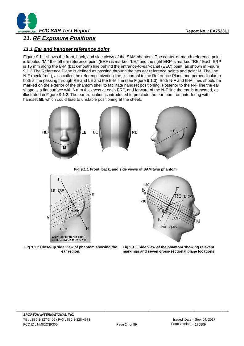
11.1 Ear and handset reference point
Figure 9.1.1 shows the front, back, and side views of the SAM phantom. The center-of-mouth reference point is labeled “M,” the left ear reference point (ERP) is marked “LE,” and the right ERP is marked “RE.” Each ERP is 15 mm along the B-M (back-mouth) line behind the entrance-to-ear-canal (EEC) point, as shown in Figure 9.1.2 The Reference Plane is defined as passing through the two ear reference points and point M. The line N-F (neck-front), also called the reference pivoting line, is normal to the Reference Plane and perpendicular to both a line passing through RE and LE and the B-M line (see Figure 9.1.3). Both N-F and B-M lines should be marked on the exterior of the phantom shell to facilitate handset positioning. Posterior to the N-F line the ear shape is a flat surface with 6 mm thickness at each ERP, and forward of the N-F line the ear is truncated, as illustrated in Figure 9.1.2. The ear truncation is introduced to preclude the ear lobe from interfering with handset tilt, which could lead to unstable positioning at the cheek.
Fig 9.1.1 Front, back, and side views of SAM twin phantom
Fig 9.1.2 Close-up side view of phantom showing the ear region.
Fig 9.1.3 Side view of the phantom showing relevant markings and seven cross-sectional plane locations

SPORTON INTERNATIONAL INC.
TEL : 886-3-327-3456 / FAX : 886-3-328-4978 Issued Date : Sep. 04, 2017
FCC ID : NM82Q3F300 Page 25 of 89 Form version. : 170509
FCC SAR Test Report Report No. : FA752311
11.2 Definition of the cheek position
1. Ready the handset for talk operation, if necessary. For example, for handsets with a cover piece (flip cover), open the cover. If the handset can transmit with the cover closed, both configurations must be tested.
2. Define two imaginary lines on the handset—the vertical centerline and the horizontal line. The vertical centerline passes through two points on the front side of the handset—the midpoint of the width wt of the handset at the level of the acoustic output (point A in Figure 9.2.1 and Figure 9.2.2), and the midpoint of the width wb of the bottom of the handset (point B). The horizontal line is perpendicular to the vertical centerline and passes through the center of the acoustic output (see Figure 9.2.1). The two lines intersect at point A. Note that for many handsets, point A coincides with the center of the acoustic output; however, the acoustic output may be located elsewhere on the horizontal line. Also note that the vertical centerline is not necessarily parallel to the front face of the handset (see Figure 9.2.2), especially for clamshell handsets, handsets with flip covers, and other irregularly-shaped handsets.
3. Position the handset close to the surface of the phantom such that point A is on the (virtual) extension of the line passing through points RE and LE on the phantom (see Figure 9.2.3), such that the plane defined by the vertical centerline and the horizontal line of the handset is approximately parallel to the sagittal plane of the phantom.
4. Translate the handset towards the phantom along the line passing through RE and LE until handset point A touches the pinna at the ERP.
5. While maintaining the handset in this plane, rotate it around the LE-RE line until the vertical centerline is in the plane normal to the plane containing B-M and N-F lines, i.e., the Reference Plane.
6. Rotate the handset around the vertical centerline until the handset (horizontal line) is parallel to the N-F line.
7. While maintaining the vertical centerline in the Reference Plane, keeping point A on the line passing through RE and LE, and maintaining the handset contact with the pinna, rotate the handset about the N-F line until any point on the handset is in contact with a phantom point below the pinna on the cheek. See Figure 9.2.3. The actual rotation angles should be documented in the test report.
Fig 9.2.1 Handset vertical and horizontal reference lines—“fixed case
Fig 9.2.2 Handset vertical and horizontal reference lines—“clam-shell case”
Fig 9.2.3 cheek or touch position. The reference points for the right ear (RE), left ear (LE), and mouth (M), which establish the Reference Plane for handset positioning, are indicated.
SPORTON INTERNATIONAL INC.
TEL : 886-3-327-3456 / FAX : 886-3-328-4978 Issued Date : Sep. 04, 2017
FCC ID : NM82Q3F300 Page 26 of 89 Form version. : 170509
FCC SAR Test Report Report No. : FA752311
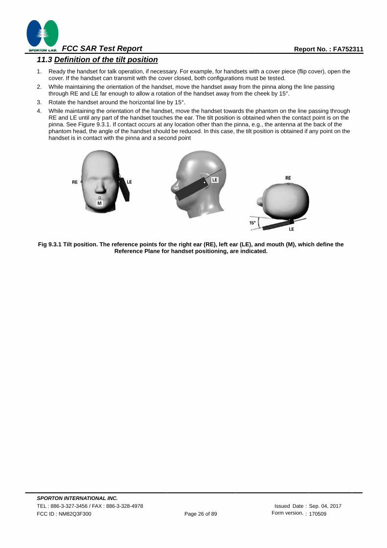
11.3 Definition of the tilt position
1. Ready the handset for talk operation, if necessary. For example, for handsets with a cover piece (flip cover), open the cover. If the handset can transmit with the cover closed, both configurations must be tested.
2. While maintaining the orientation of the handset, move the handset away from the pinna along the line passing through RE and LE far enough to allow a rotation of the handset away from the cheek by 15°.
3. Rotate the handset around the horizontal line by 15°.
4. While maintaining the orientation of the handset, move the handset towards the phantom on the line passing through RE and LE until any part of the handset touches the ear. The tilt position is obtained when the contact point is on the pinna. See Figure 9.3.1. If contact occurs at any location other than the pinna, e.g., the antenna at the back of the phantom head, the angle of the handset should be reduced. In this case, the tilt position is obtained if any point on the handset is in contact with the pinna and a second point
Fig 9.3.1 Tilt position. The reference points for the right ear (RE), left ear (LE), and mouth (M), which define the Reference Plane for handset positioning, are indicated.

SPORTON INTERNATIONAL INC.
TEL : 886-3-327-3456 / FAX : 886-3-328-4978 Issued Date : Sep. 04, 2017
FCC ID : NM82Q3F300 Page 27 of 89 Form version. : 170509
FCC SAR Test Report Report No. : FA752311
11.4 Body Worn Accessory
Body-worn operating configurations are tested with the belt-clips and holsters attached to the device and positioned against a flat phantom in a normal use configuration (see Figure 9.4). Per KDB648474 D04v01r03, body-worn accessory exposure is typically related to voice mode operations when handsets are carried in body-worn accessories. The body-worn accessory procedures in FCC KDB 447498 D01v06 should be used to test for body-worn accessory SAR compliance, without a headset connected to it. This enables the test results for such configuration to be compatible with that required for hotspot mode when the body-worn accessory test separation distance is greater than or equal to that required for hotspot mode, when applicable. When the reported SAR for body-worn accessory, measured without a headset connected to the handset is > 1.2 W/kg, the highest reported SAR configuration for that wireless mode and frequency band should be repeated for that body-worn accessory with a handset attached to the handset.
Accessories for body-worn operation configurations are divided into two categories: those that do not contain metallic components and those that do contain metallic components and those that do contain metallic components. When multiple accessories that do not contain metallic components are supplied with the device, the device is tested with only the accessory that dictates the closest spacing to the body. Then multiple accessories that contain metallic components are test with the device with each accessory. If multiple accessories share an identical metallic component (i.e. the same metallic belt-chip used with different holsters with no other metallic components) only the accessory that dictates the closest spacing to the body is tested.
Fig 9.4 Body Worn Position
11.5 Wireless Router
Some battery-operated handsets have the capability to transmit and receive user through simultaneous transmission of WIFI simultaneously with a separate licensed transmitter. The FCC has provided guidance in FCC KDB Publication 941225 D06 v02r01 where SAR test considerations for handsets (L x W ≥ 9 cm x 5 cm) are based on a composite test separation distance of 10mm from the front, back and edges of the device containing transmitting antennas within 2.5cm of their edges, determined form general mixed use conditions for this type of devices. Since the hotspot SAR results may overlap with the body-worn accessory SAR requirements, the more conservative configurations can be considered, thus excluding some body-worn accessory SAR tests.
When the user enables the personal wireless router functions for the handset, actual operations include simultaneous transmission of both the WIFI transmitter and another licensed transmitter. Both transmitters often do not transmit at the same transmitting frequency and thus cannot be evaluated for SAR under actual use conditions due to the limitations of the SAR assessment probes. Therefore, SAR must be evaluated for each frequency transmission and mode separately and spatially summed with the WIFI transmitter according to FCC KDB Publication 447498 D01v06 publication procedures. The “Portable Hotspot” feature on the handset was NOT activated during SAR assessments, to ensure the SAR measurements were evaluated for a single transmission frequency RF signal at a time.
SPORTON INTERNATIONAL INC.
TEL : 886-3-327-3456 / FAX : 886-3-328-4978 Issued Date : Sep. 04, 2017
FCC ID : NM82Q3F300 Page 28 of 89 Form version. : 170509
FCC SAR Test Report Report No. : FA752311
12. Conducted RF Output Power (Unit: dBm)
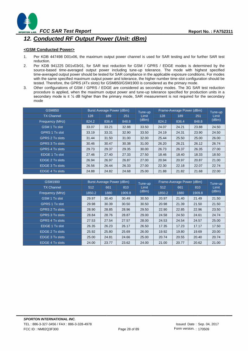
<GSM Conducted Power>
1. Per KDB 447498 D01v06, the maximum output power channel is used for SAR testing and for further SAR test reduction.
2. Per KDB 941225 D01v03r01, for SAR test reduction for GSM / GPRS / EDGE modes is determined by the source-based time-averaged output power including tune-up tolerance. The mode with highest specified time-averaged output power should be tested for SAR compliance in the applicable exposure conditions. For modes with the same specified maximum output power and tolerance, the higher number time-slot configuration should be tested. Therefore, the GPRS (4Tx slots) for GSM850/GSM1900 is considered as the primary mode.
3. Other configurations of GSM / GPRS / EDGE are considered as secondary modes. The 3G SAR test reduction procedure is applied, when the maximum output power and tune-up tolerance specified for production units in a secondary mode is ≤ ¼ dB higher than the primary mode, SAR measurement is not required for the secondary mode
GSM850 Burst Average Power (dBm) Tune-up
Limit (dBm)
Frame-Average Power (dBm) Tune-up
Limit (dBm)
TX Channel 128 189 251 128 189 251
Frequency (MHz) 824.2 836.4 848.8 824.2 836.4 848.8
GSM 1 Tx slot 33.07 33.21 32.88 33.50 24.07 24.21 23.88 24.50
GPRS 1 Tx slot 33.19 33.31 32.90 33.50 24.19 24.31 23.90 24.50
GPRS 2 Tx slots 31.44 31.50 31.00 32.00 25.44 25.50 25.00 26.00
GPRS 3 Tx slots 30.46 30.47 30.38 31.00 26.20 26.21 26.12 26.74
GPRS 4 Tx slots 29.73 29.37 29.35 30.00 26.73 26.37 26.35 27.00
EDGE 1 Tx slot 27.46 27.40 27.33 27.50 18.46 18.40 18.33 18.50
EDGE 2 Tx slots 26.94 26.97 26.87 27.00 20.94 20.97 20.87 21.00
EDGE 3 Tx slots 26.56 26.44 26.33 27.00 22.30 22.18 22.07 22.74
EDGE 4 Tx slots 24.88 24.82 24.68 25.00 21.88 21.82 21.68 22.00
GSM1900 Burst Average Power (dBm) Tune-up
Limit (dBm)
Frame-Average Power (dBm) Tune-up
Limit (dBm)
TX Channel 512 661 810 512 661 810
Frequency (MHz) 1850.2 1880 1909.8 1850.2 1880 1909.8
GSM 1 Tx slot 29.97 30.40 30.49 30.50 20.97 21.40 21.49 21.50
GPRS 1 Tx slot 29.98 30.39 30.50 30.50 20.98 21.39 21.50 21.50
GPRS 2 Tx slots 28.90 28.85 28.96 29.50 22.90 22.85 22.96 23.50
GPRS 3 Tx slots 28.84 28.76 28.87 29.00 24.58 24.50 24.61 24.74
GPRS 4 Tx slots 27.53 27.54 27.57 28.00 24.53 24.54 24.57 25.00
EDGE 1 Tx slot 26.35 26.23 26.17 26.50 17.35 17.23 17.17 17.50
EDGE 2 Tx slots 25.92 25.80 25.69 26.00 19.92 19.80 19.69 20.00
EDGE 3 Tx slots 25.00 24.81 24.66 25.00 20.74 20.55 20.40 20.74
EDGE 4 Tx slots 24.00 23.77 23.62 24.00 21.00 20.77 20.62 21.00

SPORTON INTERNATIONAL INC.
TEL : 886-3-327-3456 / FAX : 886-3-328-4978 Issued Date : Sep. 04, 2017
FCC ID : NM82Q3F300 Page 29 of 89 Form version. : 170509
FCC SAR Test Report Report No. : FA752311
<WCDMA Conducted Power>
1. The following tests were conducted according to the test requirements outlines in 3GPP TS 34.121 specification.
2. The procedures in KDB 941225 D01v03r01 are applied for 3GPP Rel. 6 HSPA to configure the device in the required
sub-test mode(s) to determine SAR test exclusion.
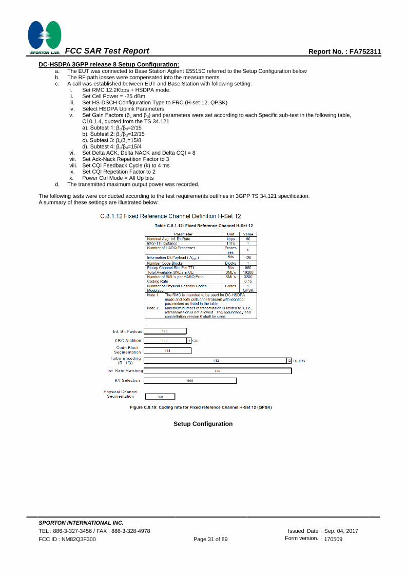
3. For DC-HSDPA, the device was configured according to the H-Set 12, Fixed Reference Channel (FRC) configuration
in Table C.8.1.12 of 3GPP TS 34.121-1, with the primary and the secondary serving HS-DSCH Cell enabled during the
power measurement.
A summary of these settings are illustrated below:
HSDPA Setup Configuration: a. The EUT was connected to Base Station Agilent E5515C referred to the Setup Configuration. b. The RF path losses were compensated into the measurements. c. A call was established between EUT and Base Station with following setting:
i. Set Gain Factors (βc and βd) and parameters were set according to each ii. Specific sub-test in the following table, C10.1.4, quoted from the TS 34.121 iii. Set RMC 12.2Kbps + HSDPA mode. iv. Set Cell Power = -86 dBm v. Set HS-DSCH Configuration Type to FRC (H-set 1, QPSK) vi. Select HSDPA Uplink Parameters vii. Set Delta ACK, Delta NACK and Delta CQI = 8 viii. Set Ack-Nack Repetition Factor to 3 ix. Set CQI Feedback Cycle (k) to 4 ms x. Set CQI Repetition Factor to 2 xi. Power Ctrl Mode = All Up bits
d. The transmitted maximum output power was recorded.
Setup Configuration

SPORTON INTERNATIONAL INC.
TEL : 886-3-327-3456 / FAX : 886-3-328-4978 Issued Date : Sep. 04, 2017
FCC ID : NM82Q3F300 Page 30 of 89 Form version. : 170509
FCC SAR Test Report Report No. : FA752311
HSUPA Setup Configuration: a. The EUT was connected to Base Station Agilent E5515C referred to the Setup Configuration. b. The RF path losses were compensated into the measurements. c. A call was established between EUT and Base Station with following setting * :
i. Call Configs = 5.2B, 5.9B, 5.10B, and 5.13.2B with QPSK ii. Set the Gain Factors (βc and βd) and parameters (AG Index) were set according to each specific sub-test in
the following table, C11.1.3, quoted from the TS 34.121 iii. Set Cell Power = -86 dBm iv. Set Channel Type = 12.2k + HSPA v. Set UE Target Power vi. Power Ctrl Mode= Alternating bits vii. Set and observe the E-TFCI viii. Confirm that E-TFCI is equal to the target E-TFCI of 75 for sub-test 1, and other subtest’s E-TFCI
d. The transmitted maximum output power was recorded.
Setup Configuration
SPORTON INTERNATIONAL INC.
TEL : 886-3-327-3456 / FAX : 886-3-328-4978 Issued Date : Sep. 04, 2017
FCC ID : NM82Q3F300 Page 31 of 89 Form version. : 170509
FCC SAR Test Report Report No. : FA752311
DC-HSDPA 3GPP release 8 Setup Configuration: a. The EUT was connected to Base Station Agilent E5515C referred to the Setup Configuration below b. The RF path losses were compensated into the measurements. c. A call was established between EUT and Base Station with following setting:
i. Set RMC 12.2Kbps + HSDPA mode. ii. Set Cell Power = -25 dBm iii. Set HS-DSCH Configuration Type to FRC (H-set 12, QPSK) iv. Select HSDPA Uplink Parameters v. Set Gain Factors (βc and βd) and parameters were set according to each Specific sub-test in the following table,
C10.1.4, quoted from the TS 34.121 a). Subtest 1: βc/βd=2/15 b). Subtest 2: βc/βd=12/15 c). Subtest 3: βc/βd=15/8 d). Subtest 4: βc/βd=15/4
vi. Set Delta ACK, Delta NACK and Delta CQI = 8 vii. Set Ack-Nack Repetition Factor to 3 viii. Set CQI Feedback Cycle (k) to 4 ms ix. Set CQI Repetition Factor to 2 x. Power Ctrl Mode = All Up bits
d. The transmitted maximum output power was recorded.
The following tests were conducted according to the test requirements outlines in 3GPP TS 34.121 specification. A summary of these settings are illustrated below:
Setup Configuration

SPORTON INTERNATIONAL INC.
TEL : 886-3-327-3456 / FAX : 886-3-328-4978 Issued Date : Sep. 04, 2017
FCC ID : NM82Q3F300 Page 32 of 89 Form version. : 170509
FCC SAR Test Report Report No. : FA752311
<WCDMA Conducted Power>
General Note:
1. Per KDB 941225 D01v03r01, for SAR testing is measured using a 12.2 kbps RMC with TPC bits configured to all “1’s”.
2. Per KDB 941225 D01v03r01, RMC 12.2kbps setting is used to evaluate SAR. The maximum output power and tune-up tolerance specified for production units in HSDPA / HSUPA / DC-HSDPA is ≤ ¼ dB higher than RMC 12.2Kbps or when the highest reported SAR of the RMC12.2Kbps is scaled by the ratio of specified maximum output power and tune-up tolerance of HSDPA / HSUPA / DC-HSDPA to RMC12.2Kbps and the adjusted SAR is ≤ 1.2 W/kg, SAR measurement is not required for HSDPA / HSUPA / DC-HSDPA, and according to the following RF output power, the output power results of the secondary modes (HSUPA, HSDPA, DC-HSDPA) are less than ¼ dB higher than the primary modes; therefore, SAR measurement is not required for HSDPA / HSUPA / DC-HSDPA.
Band WCDMA II
Tune-up Limit
(dBm)
WCDMA IV
Tune-up Limit
(dBm)
WCDMA V
Tune-up Limit
(dBm)
TX Channel 9262 9400 9538 1312 1413 1513 4132 4182 4233
Rx Channel 9662 9800 9938 1537 1638 1738 4357 4407 4458
Frequency (MHz) 1852.4 1880 1907.6 1712.4 1732.6 1752.6 826.4 836.4 846.6
3GPP Rel 99 AMR 12.2Kbps 23.21 23.58 23.62 24.50 23.58 23.80 23.70 24.50 22.91 22.93 22.61 24.50
3GPP Rel 99 RMC 12.2Kbps 23.24 23.62 23.69 24.50 23.60 23.82 23.72 24.50 22.97 22.98 22.66 24.50
3GPP Rel 6 HSDPA Subtest-1 22.56 22.71 22.69 24.50 22.59 22.87 22.70 24.50 22.00 21.98 21.66 24.50
3GPP Rel 6 HSDPA Subtest-2 22.55 22.64 22.73 24.50 22.58 22.81 22.78 24.50 22.05 22.00 21.72 24.50
3GPP Rel 6 HSDPA Subtest-3 22.11 22.15 22.23 24.00 22.13 22.30 22.28 24.00 21.56 21.51 21.23 24.00
3GPP Rel 6 HSDPA Subtest-4 22.09 22.14 22.20 24.00 22.11 22.32 22.28 24.00 21.56 21.53 21.22 24.00
3GPP Rel 8 DC-HSDPA Subtest-1 22.52 22.61 22.59 24.50 22.52 22.77 22.60 24.50 21.92 21.88 21.56 24.50
3GPP Rel 8 DC-HSDPA Subtest-2 22.51 22.57 22.52 24.50 22.51 22.71 22.66 24.50 21.91 21.90 21.61 24.50
3GPP Rel 8 DC-HSDPA Subtest-3 22.03 22.03 22.13 24.00 22.06 22.20 22.18 24.00 21.46 21.41 21.14 24.00
3GPP Rel 8 DC-HSDPA Subtest-4 22.02 22.04 22.11 24.00 22.07 22.21 22.15 24.00 21.44 21.39 21.12 24.00
3GPP Rel 6 HSUPA Subtest-1 22.54 22.60 22.68 24.50 22.54 22.79 22.77 24.50 22.01 21.98 21.67 24.50
3GPP Rel 6 HSUPA Subtest-2 20.56 20.61 20.70 22.50 20.59 20.80 20.78 22.50 20.03 20.00 19.68 22.50
3GPP Rel 6 HSUPA Subtest-3 21.58 21.61 21.65 23.50 21.50 21.73 21.71 23.50 21.00 20.98 21.65 23.50
3GPP Rel 6 HSUPA Subtest-4 20.54 20.60 20.67 22.50 20.51 20.60 20.57 22.50 20.04 20.10 19.65 22.50
3GPP Rel 6 HSUPA Subtest-5 22.51 22.58 22.61 24.50 22.51 22.75 22.73 24.50 22.00 21.91 21.36 24.50

SPORTON INTERNATIONAL INC.
TEL : 886-3-327-3456 / FAX : 886-3-328-4978 Issued Date : Sep. 04, 2017
FCC ID : NM82Q3F300 Page 33 of 89 Form version. : 170509
FCC SAR Test Report Report No. : FA752311
<LTE Conducted Power>
General Note:
1. Anritsu MT8820C base station simulator was used to setup the connection with EUT; the frequency band, channel
bandwidth, RB allocation configuration, modulation type are set in the base station simulator to configure EUT
transmitting at maximum power and at different configurations which are requested to be reported to FCC, for
conducted power measurement and SAR testing.
2. Per KDB 941225 D05v02r05, when a properly configured base station simulator is used for the SAR and power
measurements, spectrum plots for each RB allocation and offset configuration is not required.
3. Per KDB 941225 D05v02r05, start with the largest channel bandwidth and measure SAR for QPSK with 1 RB
allocation, using the RB offset and required test channel combination with the highest maximum output power for RB
offsets at the upper edge, middle and lower edge of each required test channel.
4. Per KDB 941225 D05v02r05, 50% RB allocation for QPSK SAR testing follows 1RB QPSK allocation procedure.
5. Per KDB 941225 D05v02r05, For QPSK with 100% RB allocation, SAR is not required when the highest maximum
output power for 100 % RB allocation is less than the highest maximum output power in 50% and 1 RB allocations and
the highest reported SAR for 1 RB and 50% RB allocation are ≤ 0.8 W/kg. Otherwise, SAR is measured for the highest
output power channel; and if the reported SAR is > 1.45 W/kg, the remaining required test channels must also be
tested.
6. Per KDB 941225 D05v02r05, 16QAM output power for each RB allocation configuration is > not ½ dB higher than the
same configuration in QPSK and the reported SAR for the QPSK configuration is ≤ 1.45 W/kg; Per KDB 941225
D05v02r05, 16QAM SAR testing is not required.
7. Per KDB 941225 D05v02r05, Smaller bandwidth output power for each RB allocation configuration is > not ½ dB
higher than the same configuration in the largest supported bandwidth, and the reported SAR for the largest supported
bandwidth is ≤ 1.45 W/kg; Per KDB 941225 D05v02r05, smaller bandwidth SAR testing is not required.
8. For LTE B12 / B5 the maximum bandwidth does not support three non-overlapping channels, per KDB 941225
D05v02r05, when a device supports overlapping channel assignment in a channel bandwidth configuration, the middle
channel of the group of overlapping channels should be selected for testing.
9. LTE band 4 / 17 SAR test was covered by Band 66 / 12; according to April 2015 TCB workshop, SAR test for
overlapping LTE bands can be reduced if
a. the maximum output power, including tolerance, for the smaller band is ≤ the larger band to qualify for the SAR
test exclusion
b. the channel bandwidth and other operating parameters for the smaller band are fully supported by the larger
band

SPORTON INTERNATIONAL INC.
TEL : 886-3-327-3456 / FAX : 886-3-328-4978 Issued Date : Sep. 04, 2017
FCC ID : NM82Q3F300 Page 34 of 89 Form version. : 170509
FCC SAR Test Report Report No. : FA752311
<LTE Band 2>
BW [MHz] Modulation RB Size RB Offset Power Low
Ch. / Freq.
Power Middle
Ch. / Freq.
Power High
Ch. / Freq. Tune-up limit (dBm)
MPR (dB) Channel 18700 18900 19100
Frequency (MHz) 1860 1880 1900
20 QPSK 1 0 22.65 22.74 22.80
24 0 20 QPSK 1 49 22.50 22.59 22.65
20 QPSK 1 99 22.42 22.66 22.72
20 QPSK 50 0 21.65 21.77 21.91
23 1 20 QPSK 50 24 21.59 21.73 21.84
20 QPSK 50 50 21.56 21.75 21.90
20 QPSK 100 0 21.52 21.69 21.77
20 16QAM 1 0 21.82 21.85 21.94
23 1 20 16QAM 1 49 21.71 21.79 21.90
20 16QAM 1 99 21.67 21.90 21.91
20 16QAM 50 0 20.63 20.80 20.91
22 2 20 16QAM 50 24 20.66 20.73 20.84
20 16QAM 50 50 20.59 20.65 20.82
20 16QAM 100 0 20.53 20.76 20.85
Channel 18675 18900 19125 Tune-up limit (dBm)
MPR (dB) Frequency (MHz) 1857.5 1880 1902.5
15 QPSK 1 0 22.45 22.57 22.61
24 0 15 QPSK 1 37 22.30 22.45 22.53
15 QPSK 1 74 22.37 22.59 22.67
15 QPSK 36 0 21.45 21.66 21.75
23 1 15 QPSK 36 20 21.40 21.63 21.67
15 QPSK 36 39 21.48 21.58 21.79
15 QPSK 75 0 21.42 21.67 21.71
15 16QAM 1 0 21.82 21.88 21.91
23 1 15 16QAM 1 37 21.59 21.65 21.76
15 16QAM 1 74 21.76 21.84 21.91
15 16QAM 36 0 20.45 20.62 20.70
22 2 15 16QAM 36 20 20.44 20.66 20.69
15 16QAM 36 39 20.48 20.55 20.74
15 16QAM 75 0 20.38 20.45 20.64
Channel 18650 18900 19150 Tune-up limit (dBm)
MPR (dB) Frequency (MHz) 1855 1880 1905
10 QPSK 1 0 22.66 22.57 22.63
24 0 10 QPSK 1 25 22.67 22.48 22.68
10 QPSK 1 49 22.62 22.48 22.64
10 QPSK 25 0 21.44 21.63 21.67
23 1 10 QPSK 25 12 21.45 21.59 21.78
10 QPSK 25 25 21.39 21.57 21.74
10 QPSK 50 0 21.43 21.61 21.77
10 16QAM 1 0 21.76 21.80 21.87
23 1 10 16QAM 1 25 21.68 21.69 21.90
10 16QAM 1 49 21.69 21.69 21.89
10 16QAM 25 0 20.40 20.58 20.69
22 2 10 16QAM 25 12 20.43 20.60 20.74
10 16QAM 25 25 20.36 20.54 20.73
10 16QAM 50 0 20.41 20.60 20.80
SPORTON INTERNATIONAL INC.
TEL : 886-3-327-3456 / FAX : 886-3-328-4978 Issued Date : Sep. 04, 2017
FCC ID : NM82Q3F300 Page 35 of 89 Form version. : 170509
FCC SAR Test Report Report No. : FA752311
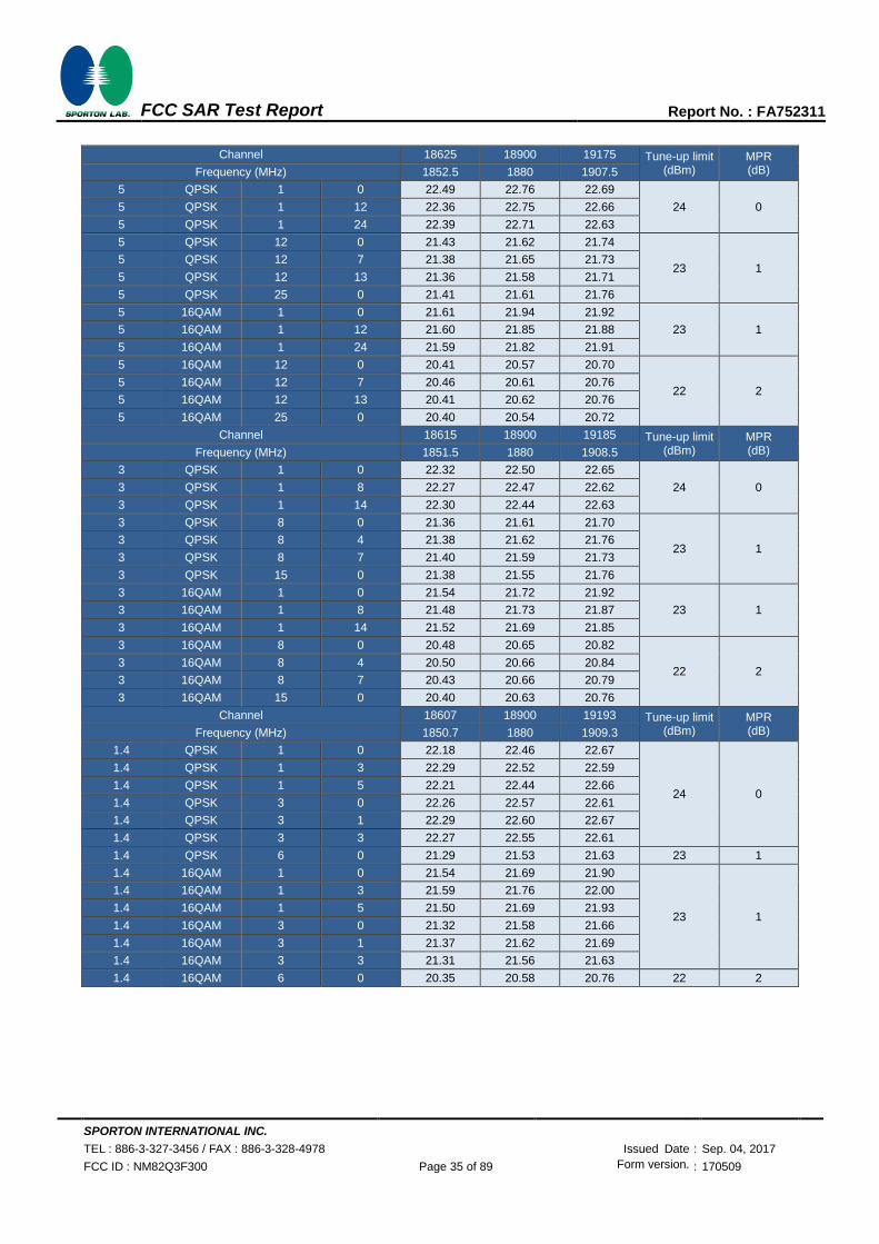
Channel 18625 18900 19175 Tune-up limit
(dBm) MPR (dB) Frequency (MHz) 1852.5 1880 1907.5
5 QPSK 1 0 22.49 22.76 22.69
24 0 5 QPSK 1 12 22.36 22.75 22.66
5 QPSK 1 24 22.39 22.71 22.63
5 QPSK 12 0 21.43 21.62 21.74
23 1 5 QPSK 12 7 21.38 21.65 21.73
5 QPSK 12 13 21.36 21.58 21.71
5 QPSK 25 0 21.41 21.61 21.76
5 16QAM 1 0 21.61 21.94 21.92
23 1 5 16QAM 1 12 21.60 21.85 21.88
5 16QAM 1 24 21.59 21.82 21.91
5 16QAM 12 0 20.41 20.57 20.70
22 2 5 16QAM 12 7 20.46 20.61 20.76
5 16QAM 12 13 20.41 20.62 20.76
5 16QAM 25 0 20.40 20.54 20.72
Channel 18615 18900 19185 Tune-up limit (dBm)
MPR (dB) Frequency (MHz) 1851.5 1880 1908.5
3 QPSK 1 0 22.32 22.50 22.65
24 0 3 QPSK 1 8 22.27 22.47 22.62
3 QPSK 1 14 22.30 22.44 22.63
3 QPSK 8 0 21.36 21.61 21.70
23 1 3 QPSK 8 4 21.38 21.62 21.76
3 QPSK 8 7 21.40 21.59 21.73
3 QPSK 15 0 21.38 21.55 21.76
3 16QAM 1 0 21.54 21.72 21.92
23 1 3 16QAM 1 8 21.48 21.73 21.87
3 16QAM 1 14 21.52 21.69 21.85
3 16QAM 8 0 20.48 20.65 20.82
22 2 3 16QAM 8 4 20.50 20.66 20.84
3 16QAM 8 7 20.43 20.66 20.79
3 16QAM 15 0 20.40 20.63 20.76
Channel 18607 18900 19193 Tune-up limit (dBm)
MPR (dB) Frequency (MHz) 1850.7 1880 1909.3
1.4 QPSK 1 0 22.18 22.46 22.67
24 0
1.4 QPSK 1 3 22.29 22.52 22.59
1.4 QPSK 1 5 22.21 22.44 22.66
1.4 QPSK 3 0 22.26 22.57 22.61
1.4 QPSK 3 1 22.29 22.60 22.67
1.4 QPSK 3 3 22.27 22.55 22.61
1.4 QPSK 6 0 21.29 21.53 21.63 23 1
1.4 16QAM 1 0 21.54 21.69 21.90
23 1
1.4 16QAM 1 3 21.59 21.76 22.00
1.4 16QAM 1 5 21.50 21.69 21.93
1.4 16QAM 3 0 21.32 21.58 21.66
1.4 16QAM 3 1 21.37 21.62 21.69
1.4 16QAM 3 3 21.31 21.56 21.63
1.4 16QAM 6 0 20.35 20.58 20.76 22 2
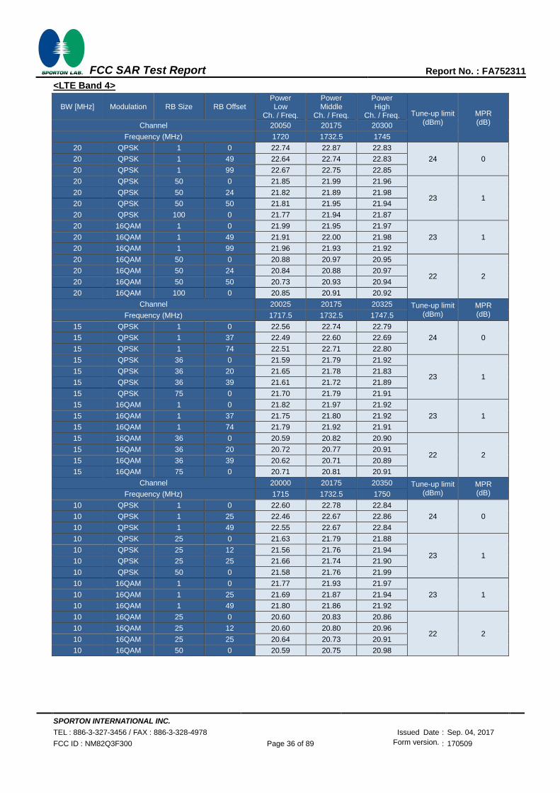
SPORTON INTERNATIONAL INC.
TEL : 886-3-327-3456 / FAX : 886-3-328-4978 Issued Date : Sep. 04, 2017
FCC ID : NM82Q3F300 Page 36 of 89 Form version. : 170509
FCC SAR Test Report Report No. : FA752311
<LTE Band 4>
BW [MHz] Modulation RB Size RB Offset Power Low
Ch. / Freq.
Power Middle
Ch. / Freq.
Power High
Ch. / Freq. Tune-up limit (dBm)
MPR (dB) Channel 20050 20175 20300
Frequency (MHz) 1720 1732.5 1745
20 QPSK 1 0 22.74 22.87 22.83
24 0 20 QPSK 1 49 22.64 22.74 22.83
20 QPSK 1 99 22.67 22.75 22.85
20 QPSK 50 0 21.85 21.99 21.96
23 1 20 QPSK 50 24 21.82 21.89 21.98
20 QPSK 50 50 21.81 21.95 21.94
20 QPSK 100 0 21.77 21.94 21.87
20 16QAM 1 0 21.99 21.95 21.97
23 1 20 16QAM 1 49 21.91 22.00 21.98
20 16QAM 1 99 21.96 21.93 21.92
20 16QAM 50 0 20.88 20.97 20.95
22 2 20 16QAM 50 24 20.84 20.88 20.97
20 16QAM 50 50 20.73 20.93 20.94
20 16QAM 100 0 20.85 20.91 20.92
Channel 20025 20175 20325 Tune-up limit (dBm)
MPR (dB) Frequency (MHz) 1717.5 1732.5 1747.5
15 QPSK 1 0 22.56 22.74 22.79
24 0 15 QPSK 1 37 22.49 22.60 22.69
15 QPSK 1 74 22.51 22.71 22.80
15 QPSK 36 0 21.59 21.79 21.92
23 1 15 QPSK 36 20 21.65 21.78 21.83
15 QPSK 36 39 21.61 21.72 21.89
15 QPSK 75 0 21.70 21.79 21.91
15 16QAM 1 0 21.82 21.97 21.92
23 1 15 16QAM 1 37 21.75 21.80 21.92
15 16QAM 1 74 21.79 21.92 21.91
15 16QAM 36 0 20.59 20.82 20.90
22 2 15 16QAM 36 20 20.72 20.77 20.91
15 16QAM 36 39 20.62 20.71 20.89
15 16QAM 75 0 20.71 20.81 20.91
Channel 20000 20175 20350 Tune-up limit (dBm)
MPR (dB) Frequency (MHz) 1715 1732.5 1750
10 QPSK 1 0 22.60 22.78 22.84
24 0 10 QPSK 1 25 22.46 22.67 22.86
10 QPSK 1 49 22.55 22.67 22.84
10 QPSK 25 0 21.63 21.79 21.88
23 1 10 QPSK 25 12 21.56 21.76 21.94
10 QPSK 25 25 21.66 21.74 21.90
10 QPSK 50 0 21.58 21.76 21.99
10 16QAM 1 0 21.77 21.93 21.97
23 1 10 16QAM 1 25 21.69 21.87 21.94
10 16QAM 1 49 21.80 21.86 21.92
10 16QAM 25 0 20.60 20.83 20.86
22 2 10 16QAM 25 12 20.60 20.80 20.96
10 16QAM 25 25 20.64 20.73 20.91
10 16QAM 50 0 20.59 20.75 20.98

SPORTON INTERNATIONAL INC.
TEL : 886-3-327-3456 / FAX : 886-3-328-4978 Issued Date : Sep. 04, 2017
FCC ID : NM82Q3F300 Page 37 of 89 Form version. : 170509
FCC SAR Test Report Report No. : FA752311
Channel 19975 20175 20375 Tune-up limit
(dBm) MPR (dB) Frequency (MHz) 1712.5 1732.5 1752.5
5 QPSK 1 0 22.51 22.70 22.79
24 0 5 QPSK 1 12 22.50 22.68 22.83
5 QPSK 1 24 22.46 22.65 22.84
5 QPSK 12 0 21.58 21.78 21.99
23 1 5 QPSK 12 7 21.60 21.77 21.99
5 QPSK 12 13 21.55 21.77 21.92
5 QPSK 25 0 21.58 21.73 21.94
5 16QAM 1 0 21.73 21.90 21.93
23 1 5 16QAM 1 12 21.67 21.84 21.94
5 16QAM 1 24 21.70 21.89 21.88
5 16QAM 12 0 20.57 20.76 20.96
22 2 5 16QAM 12 7 20.64 20.76 20.99
5 16QAM 12 13 20.60 20.77 20.92
5 16QAM 25 0 20.58 20.74 20.95
Channel 19965 20175 20385 Tune-up limit (dBm)
MPR (dB) Frequency (MHz) 1711.5 1732.5 1753.5
3 QPSK 1 0 22.49 22.68 22.76
24 0 3 QPSK 1 8 22.52 22.68 22.82
3 QPSK 1 14 22.48 22.64 22.8
3 QPSK 8 0 21.6 21.78 21.93
23 1 3 QPSK 8 4 21.61 21.76 21.99
3 QPSK 8 7 21.56 21.74 21.89
3 QPSK 15 0 21.56 21.76 21.91
3 16QAM 1 0 21.74 21.9 21.96
23 1 3 16QAM 1 8 21.71 21.86 21.97
3 16QAM 1 14 21.71 21.89 21.94
3 16QAM 8 0 20.65 20.82 20.95
22 2 3 16QAM 8 4 20.66 20.85 20.94
3 16QAM 8 7 20.62 20.79 20.91
3 16QAM 15 0 20.6 20.78 20.99
Channel 19957 20175 20393 Tune-up limit (dBm)
MPR (dB) Frequency (MHz) 1710.7 1732.5 1754.3
1.4 QPSK 1 0 22.37 22.59 22.73
24 0
1.4 QPSK 1 3 22.48 22.62 22.83
1.4 QPSK 1 5 22.35 22.55 22.77
1.4 QPSK 3 0 22.49 22.75 22.85
1.4 QPSK 3 1 22.48 22.79 22.82
1.4 QPSK 3 3 22.50 22.82 22.86
1.4 QPSK 6 0 21.47 21.68 21.89 23 1
1.4 16QAM 1 0 21.59 21.82 21.94
23 1
1.4 16QAM 1 3 21.65 21.87 21.98
1.4 16QAM 1 5 21.61 21.80 21.91
1.4 16QAM 3 0 21.42 21.64 21.85
1.4 16QAM 3 1 21.54 21.68 21.88
1.4 16QAM 3 3 21.42 21.63 21.83
1.4 16QAM 6 0 20.55 20.74 20.96 22 2

SPORTON INTERNATIONAL INC.
TEL : 886-3-327-3456 / FAX : 886-3-328-4978 Issued Date : Sep. 04, 2017
FCC ID : NM82Q3F300 Page 38 of 89 Form version. : 170509
FCC SAR Test Report Report No. : FA752311
<LTE Band 5>
BW [MHz] Modulation RB Size RB Offset Power Low
Ch. / Freq.
Power Middle
Ch. / Freq.
Power High
Ch. / Freq. Tune-up limit (dBm)
MPR (dB) Channel 20450 20525 20600
Frequency (MHz) 829 836.5 844
10 QPSK 1 0 22.82 22.63 22.51
24 0 10 QPSK 1 25 22.76 22.51 22.37
10 QPSK 1 49 22.56 22.44 22.29
10 QPSK 25 0 21.87 21.63 21.46
23 1 10 QPSK 25 12 21.80 21.61 21.45
10 QPSK 25 25 21.69 21.60 21.40
10 QPSK 50 0 21.79 21.68 21.42
10 16QAM 1 0 21.93 21.81 21.70
23 1 10 16QAM 1 25 21.94 21.71 21.56
10 16QAM 1 49 21.77 21.64 21.45
10 16QAM 25 0 20.85 20.63 20.45
22 2 10 16QAM 25 12 20.82 20.62 20.41
10 16QAM 25 25 20.68 20.58 20.38
10 16QAM 50 0 20.79 20.59 20.42
Channel 20425 20525 20625 Tune-up limit (dBm)
MPR (dB) Frequency (MHz) 826.5 836.5 846.5
5 QPSK 1 0 22.77 22.57 22.34
24 0 5 QPSK 1 12 22.77 22.52 22.33
5 QPSK 1 24 22.71 22.51 22.31
5 QPSK 12 0 21.83 21.66 21.40
23 1 5 QPSK 12 7 21.88 21.64 21.41
5 QPSK 12 13 21.83 21.57 21.41
5 QPSK 25 0 21.82 21.62 21.43
5 16QAM 1 0 21.94 21.80 21.60
23 1 5 16QAM 1 12 21.99 21.73 21.52
5 16QAM 1 24 21.91 21.73 21.54
5 16QAM 12 0 20.85 20.59 20.46
22 2 5 16QAM 12 7 20.90 20.63 20.46
5 16QAM 12 13 20.83 20.60 20.35
5 16QAM 25 0 20.84 20.60 20.42
Channel 20415 20525 20635 Tune-up limit (dBm)
MPR (dB) Frequency (MHz) 825.5 836.5 847.5
3 QPSK 1 0 22.80 22.58 22.33
24 0 3 QPSK 1 8 22.76 22.52 22.34
3 QPSK 1 14 22.73 22.54 22.29
3 QPSK 8 0 21.88 21.60 21.41
23 1 3 QPSK 8 4 21.86 21.67 21.45
3 QPSK 8 7 21.82 21.57 21.42
3 QPSK 15 0 21.86 21.58 21.39
3 16QAM 1 0 22.00 21.79 21.55
23 1 3 16QAM 1 8 21.95 21.79 21.54
3 16QAM 1 14 21.97 21.74 21.53
3 16QAM 8 0 20.95 20.74 20.45
22 2 3 16QAM 8 4 20.91 20.74 20.53
3 16QAM 8 7 20.89 20.64 20.52
3 16QAM 15 0 20.89 20.62 20.45

SPORTON INTERNATIONAL INC.
TEL : 886-3-327-3456 / FAX : 886-3-328-4978 Issued Date : Sep. 04, 2017
FCC ID : NM82Q3F300 Page 39 of 89 Form version. : 170509
FCC SAR Test Report Report No. : FA752311
Channel 20407 20525 20643 Tune-up limit
(dBm) MPR (dB) Frequency (MHz) 824.7 836.5 848.3
1.4 QPSK 1 0 22.72 22.47 22.20
24 0
1.4 QPSK 1 3 22.79 22.47 22.27
1.4 QPSK 1 5 22.72 22.42 22.21
1.4 QPSK 3 0 22.77 22.58 22.37
1.4 QPSK 3 1 22.78 22.61 22.39
1.4 QPSK 3 3 22.75 22.59 22.36
1.4 QPSK 6 0 21.81 21.53 21.35 23 1
1.4 16QAM 1 0 21.98 21.68 21.45
23 1
1.4 16QAM 1 3 22.00 21.76 21.56
1.4 16QAM 1 5 22.00 21.71 21.43
1.4 16QAM 3 0 21.81 21.54 21.28
1.4 16QAM 3 1 21.84 21.56 21.31
1.4 16QAM 3 3 21.78 21.53 21.29
1.4 16QAM 6 0 20.88 20.62 20.39 22 2
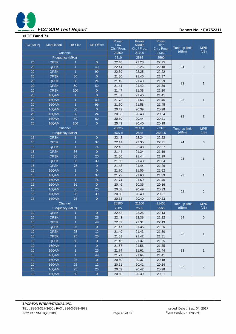
SPORTON INTERNATIONAL INC.
TEL : 886-3-327-3456 / FAX : 886-3-328-4978 Issued Date : Sep. 04, 2017
FCC ID : NM82Q3F300 Page 40 of 89 Form version. : 170509
FCC SAR Test Report Report No. : FA752311
<LTE Band 7>
BW [MHz] Modulation RB Size RB Offset Power Low
Ch. / Freq.
Power Middle
Ch. / Freq.
Power High
Ch. / Freq. Tune-up limit (dBm)
MPR (dB) Channel 20850 21100 21350
Frequency (MHz) 2510 2535 2560
20 QPSK 1 0 22.48 22.28 22.25
24 0 20 QPSK 1 49 22.44 22.26 22.18
20 QPSK 1 99 22.39 22.25 22.22
20 QPSK 50 0 21.50 21.46 21.37
23 1 20 QPSK 50 24 21.49 21.40 21.29
20 QPSK 50 50 21.44 21.42 21.36
20 QPSK 100 0 21.47 21.38 21.20
20 16QAM 1 0 21.51 21.46 21.41
23 1 20 16QAM 1 49 21.73 21.66 21.46
20 16QAM 1 99 21.70 21.58 21.45
20 16QAM 50 0 20.42 20.39 20.28
22 2 20 16QAM 50 24 20.53 20.43 20.24
20 16QAM 50 50 20.50 20.44 20.21
20 16QAM 100 0 20.43 20.40 20.18
Channel 20825 21100 21375 Tune-up limit (dBm)
MPR (dB) Frequency (MHz) 2507.5 2535 2562.5
15 QPSK 1 0 22.42 22.24 22.22
24 0 15 QPSK 1 37 22.41 22.35 22.21
15 QPSK 1 74 22.42 22.38 22.27
15 QPSK 36 0 21.44 21.34 21.19
23 1 15 QPSK 36 20 21.56 21.44 21.29
15 QPSK 36 39 21.55 21.43 21.34
15 QPSK 75 0 21.48 21.44 21.26
15 16QAM 1 0 21.70 21.56 21.52
23 1 15 16QAM 1 37 21.79 21.60 21.39
15 16QAM 1 74 21.74 21.69 21.46
15 16QAM 36 0 20.46 20.36 20.16
22 2 15 16QAM 36 20 20.58 20.49 20.33
15 16QAM 36 39 20.50 20.40 20.31
15 16QAM 75 0 20.52 20.40 20.23
Channel 20800 21100 21400 Tune-up limit (dBm)
MPR (dB) Frequency (MHz) 2505 2535 2565
10 QPSK 1 0 22.42 22.25 22.13
24 0 10 QPSK 1 25 22.43 22.35 22.22
10 QPSK 1 49 22.39 22.31 22.19
10 QPSK 25 0 21.47 21.35 21.25
23 1 10 QPSK 25 12 21.49 21.43 21.30
10 QPSK 25 25 21.51 21.42 21.31
10 QPSK 50 0 21.45 21.37 21.25
10 16QAM 1 0 21.67 21.56 21.35
23 1 10 16QAM 1 25 21.74 21.61 21.44
10 16QAM 1 49 21.71 21.64 21.41
10 16QAM 25 0 20.50 20.37 20.18
22 2 10 16QAM 25 12 20.51 20.41 20.24
10 16QAM 25 25 20.52 20.42 20.28
10 16QAM 50 0 20.50 20.39 20.21

SPORTON INTERNATIONAL INC.
TEL : 886-3-327-3456 / FAX : 886-3-328-4978 Issued Date : Sep. 04, 2017
FCC ID : NM82Q3F300 Page 41 of 89 Form version. : 170509
FCC SAR Test Report Report No. : FA752311
Channel 20775 21100 21425 Tune-up limit
(dBm) MPR (dB) Frequency (MHz) 2502.5 2535 2567.5
5 QPSK 1 0 22.44 22.26 22.12
24 0 5 QPSK 1 12 22.44 22.31 22.18
5 QPSK 1 24 22.44 22.30 22.14
5 QPSK 12 0 21.48 21.39 21.17
23 1 5 QPSK 12 7 21.56 21.43 21.25
5 QPSK 12 13 21.51 21.38 21.25
5 QPSK 25 0 21.49 21.38 21.21
5 16QAM 1 0 21.71 21.56 21.40
23 1 5 16QAM 1 12 21.72 21.57 21.37
5 16QAM 1 24 21.74 21.63 21.44
5 16QAM 12 0 20.56 20.37 20.18
22 2 5 16QAM 12 7 20.59 20.48 20.29
5 16QAM 12 13 20.55 20.44 20.25
5 16QAM 25 0 20.51 20.36 20.20
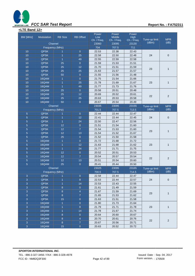
SPORTON INTERNATIONAL INC.
TEL : 886-3-327-3456 / FAX : 886-3-328-4978 Issued Date : Sep. 04, 2017
FCC ID : NM82Q3F300 Page 42 of 89 Form version. : 170509
FCC SAR Test Report Report No. : FA752311
<LTE Band 12>
BW [MHz] Modulation RB Size RB Offset Power Low
Ch. / Freq.
Power Middle
Ch. / Freq.
Power High
Ch. / Freq. Tune-up limit (dBm)
MPR (dB) Channel 23060 23095 23130
Frequency (MHz) 704 707.5 711
10 QPSK 1 0 22.53 22.38 22.43
24 0 10 QPSK 1 25 22.58 22.50 22.48
10 QPSK 1 49 22.55 22.59 22.58
10 QPSK 25 0 21.59 21.53 21.51
23 1 10 QPSK 25 12 21.70 21.51 21.59
10 QPSK 25 25 21.63 21.57 21.57
10 QPSK 50 0 21.55 21.56 21.48
10 16QAM 1 0 21.75 21.54 21.66
23 1 10 16QAM 1 25 21.78 21.69 21.67
10 16QAM 1 49 21.77 21.73 21.76
10 16QAM 25 0 20.58 20.51 20.48
22 2 10 16QAM 25 12 20.69 20.52 20.61
10 16QAM 25 25 20.63 20.53 20.58
10 16QAM 50 0 20.67 20.54 20.49
Channel 23035 23095 23155 Tune-up limit (dBm)
MPR (dB) Frequency (MHz) 701.5 707.5 713.5
5 QPSK 1 0 22.44 22.44 22.47
24 0 5 QPSK 1 12 22.41 22.44 22.45
5 QPSK 1 24 22.50 22.47 22.56
5 QPSK 12 0 21.51 21.54 21.60
23 1 5 QPSK 12 7 21.54 21.53 21.60
5 QPSK 12 13 21.54 21.52 21.67
5 QPSK 25 0 21.52 21.50 21.58
5 16QAM 1 0 21.72 21.68 21.72
23 1 5 16QAM 1 12 21.63 21.68 21.62
5 16QAM 1 24 21.77 21.71 21.75
5 16QAM 12 0 20.52 20.51 20.53
22 2 5 16QAM 12 7 20.54 20.57 20.54
5 16QAM 12 13 20.51 20.54 20.60
5 16QAM 25 0 20.41 20.44 20.50
Channel 23025 23095 23165 Tune-up limit (dBm)
MPR (dB) Frequency (MHz) 700.5 707.5 714.5
3 QPSK 1 0 22.58 22.44 22.47
24 0 3 QPSK 1 8 22.53 22.44 22.57
3 QPSK 1 14 22.53 22.43 22.55
3 QPSK 8 0 21.61 21.49 21.59
23 1 3 QPSK 8 4 21.67 21.59 21.69
3 QPSK 8 7 21.65 21.53 21.62
3 QPSK 15 0 21.63 21.51 21.58
3 16QAM 1 0 21.80 21.73 21.64
23 1 3 16QAM 1 8 21.79 21.71 21.78
3 16QAM 1 14 21.78 21.67 21.74
3 16QAM 8 0 20.64 20.60 20.67
22 2 3 16QAM 8 4 20.70 20.61 20.76
3 16QAM 8 7 20.67 20.56 20.71
3 16QAM 15 0 20.63 20.52 20.72
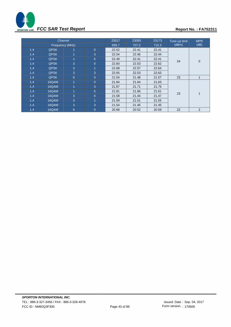
SPORTON INTERNATIONAL INC.
TEL : 886-3-327-3456 / FAX : 886-3-328-4978 Issued Date : Sep. 04, 2017
FCC ID : NM82Q3F300 Page 43 of 89 Form version. : 170509
FCC SAR Test Report Report No. : FA752311
Channel 23017 23095 23173 Tune-up limit
(dBm) MPR (dB) Frequency (MHz) 699.7 707.5 715.3
1.4 QPSK 1 0 22.52 22.41 22.41
24 0
1.4 QPSK 1 3 22.54 22.46 22.44
1.4 QPSK 1 5 22.49 22.41 22.41
1.4 QPSK 3 0 22.60 22.53 22.62
1.4 QPSK 3 1 22.68 22.57 22.64
1.4 QPSK 3 3 22.65 22.53 22.63
1.4 QPSK 6 0 21.54 21.48 21.57 23 1
1.4 16QAM 1 0 21.84 21.64 21.63
23 1
1.4 16QAM 1 3 21.87 21.71 21.76
1.4 16QAM 1 5 21.81 21.66 21.61
1.4 16QAM 3 0 21.58 21.44 21.47
1.4 16QAM 3 1 21.59 21.51 21.55
1.4 16QAM 3 3 21.54 21.45 21.45
1.4 16QAM 6 0 20.68 20.52 20.59 22 2

SPORTON INTERNATIONAL INC.
TEL : 886-3-327-3456 / FAX : 886-3-328-4978 Issued Date : Sep. 04, 2017
FCC ID : NM82Q3F300 Page 44 of 89 Form version. : 170509
FCC SAR Test Report Report No. : FA752311
<LTE Band 13>
BW [MHz] Modulation RB Size RB Offset Power Low
Ch. / Freq.
Power Middle
Ch. / Freq.
Power High
Ch. / Freq. Tune-up limit (dBm)
MPR (dB) Channel 23230
Frequency (MHz) 782
10 QPSK 1 0 22.57
24 0 10 QPSK 1 25 22.59
10 QPSK 1 49 22.65
10 QPSK 25 0 21.53
23 1 10 QPSK 25 12 21.69
10 QPSK 25 25 21.74
10 QPSK 50 0 21.66
10 16QAM 1 0 21.78
23 1 10 16QAM 1 25 21.80
10 16QAM 1 49 21.79
10 16QAM 25 0 20.55
22 2 10 16QAM 25 12 20.67
10 16QAM 25 25 20.69
10 16QAM 50 0 20.67
Channel 23205 23230 23255 Tune-up limit (dBm)
MPR (dB) Frequency (MHz) 779.5 782 784.5
5 QPSK 1 0 22.64 22.47 22.61
24 0 5 QPSK 1 12 22.61 22.57 22.63
5 QPSK 1 24 22.60 22.53 22.60
5 QPSK 12 0 21.74 21.70 21.61
23 1 5 QPSK 12 7 21.68 21.72 21.77
5 QPSK 12 13 21.76 21.67 21.73
5 QPSK 25 0 21.65 21.63 21.71
5 16QAM 1 0 21.94 21.71 21.85
23 1 5 16QAM 1 12 21.79 21.79 21.85
5 16QAM 1 24 21.91 21.80 21.83
5 16QAM 12 0 20.70 20.67 20.63
22 2 5 16QAM 12 7 20.70 20.68 20.76
5 16QAM 12 13 20.75 20.67 20.73
5 16QAM 25 0 20.68 20.63 20.70

SPORTON INTERNATIONAL INC.
TEL : 886-3-327-3456 / FAX : 886-3-328-4978 Issued Date : Sep. 04, 2017
FCC ID : NM82Q3F300 Page 45 of 89 Form version. : 170509
FCC SAR Test Report Report No. : FA752311
<LTE Band 17>
BW [MHz] Modulation RB Size RB Offset Power Low
Ch. / Freq.
Power Middle
Ch. / Freq.
Power High
Ch. / Freq. Tune-up limit (dBm)
MPR (dB) Channel 23780 23790 23800
Frequency (MHz) 709 710 711
10 QPSK 1 0 22.31 22.31 22.42
24 0 10 QPSK 1 25 22.42 22.38 22.47
10 QPSK 1 49 22.57 22.58 22.57
10 QPSK 25 0 21.47 21.45 21.48
23 1 10 QPSK 25 12 21.51 21.51 21.50
10 QPSK 25 25 21.57 21.65 21.65
10 QPSK 50 0 21.47 21.57 21.56
10 16QAM 1 0 21.52 21.49 21.59
23 1 10 16QAM 1 25 21.58 21.58 21.63
10 16QAM 1 49 21.76 21.74 21.75
10 16QAM 25 0 20.45 20.48 20.47
22 2 10 16QAM 25 12 20.49 20.49 20.49
10 16QAM 25 25 20.56 20.65 20.66
10 16QAM 50 0 20.55 20.58 20.57
Channel 23755 23790 23825 Tune-up limit (dBm)
MPR (dB) Frequency (MHz) 706.5 710 713.5
5 QPSK 1 0 22.30 22.39 22.45
24 0 5 QPSK 1 12 22.42 22.38 22.56
5 QPSK 1 24 22.41 22.48 22.54
5 QPSK 12 0 21.37 21.46 21.59
23 1 5 QPSK 12 7 21.52 21.49 21.68
5 QPSK 12 13 21.50 21.62 21.68
5 QPSK 25 0 21.52 21.48 21.66
5 16QAM 1 0 21.53 21.64 21.64
23 1 5 16QAM 1 12 21.64 21.58 21.70
5 16QAM 1 24 21.65 21.66 21.74
5 16QAM 12 0 20.37 20.51 20.50
22 2 5 16QAM 12 7 20.58 20.55 20.62
5 16QAM 12 13 20.58 20.63 20.59
5 16QAM 25 0 20.51 20.47 20.67

SPORTON INTERNATIONAL INC.
TEL : 886-3-327-3456 / FAX : 886-3-328-4978 Issued Date : Sep. 04, 2017
FCC ID : NM82Q3F300 Page 46 of 89 Form version. : 170509
FCC SAR Test Report Report No. : FA752311
<LTE Band 66>
BW [MHz] Modulation RB Size RB Offset Power Low
Ch. / Freq.
Power Middle
Ch. / Freq.
Power High
Ch. / Freq. Tune-up limit (dBm)
MPR (dB) Channel 132072 132322 132572
Frequency (MHz) 1720 1745 1770
20 QPSK 1 0 22.68 22.89 22.96
24 0 20 QPSK 1 49 22.57 22.82 22.90
20 QPSK 1 99 22.61 22.77 22.75
20 QPSK 50 0 21.81 21.96 21.98
23 1 20 QPSK 50 24 21.76 21.97 21.95
20 QPSK 50 50 21.79 21.94 21.92
20 QPSK 100 0 21.68 21.95 21.97
20 16QAM 1 0 21.84 21.95 21.99
23 1 20 16QAM 1 49 21.82 21.84 21.92
20 16QAM 1 99 21.89 21.96 21.93
20 16QAM 50 0 20.80 20.89 20.95
22 2 20 16QAM 50 24 20.78 20.99 20.88
20 16QAM 50 50 20.76 20.89 20.96
20 16QAM 100 0 20.78 20.82 20.89
Channel 132047 132322 132597 Tune-up limit (dBm)
MPR (dB) Frequency (MHz) 1717.5 1745 1772.5
15 QPSK 1 0 22.67 22.88 22.95
24 0 15 QPSK 1 37 22.50 22.85 22.80
15 QPSK 1 74 22.62 22.82 22.83
15 QPSK 36 0 21.71 21.91 21.96
23 1 15 QPSK 36 20 21.67 21.99 21.95
15 QPSK 36 39 21.73 21.91 21.96
15 QPSK 75 0 21.72 21.92 21.94
15 16QAM 1 0 21.93 21.96 21.98
23 1 15 16QAM 1 37 21.77 21.88 21.84
15 16QAM 1 74 21.88 21.89 21.91
15 16QAM 36 0 20.70 20.92 20.90
22 2 15 16QAM 36 20 20.74 20.99 20.94
15 16QAM 36 39 20.73 20.92 20.96
15 16QAM 75 0 20.72 20.98 21.04
Channel 132022 132322 132622 Tune-up limit (dBm)
MPR (dB) Frequency (MHz) 1715 1745 1775
10 QPSK 1 0 22.61 22.96 22.62
24 0 10 QPSK 1 25 22.54 22.87 22.48
10 QPSK 1 49 22.52 22.86 22.59
10 QPSK 25 0 21.69 22.00 21.94
23 1 10 QPSK 25 12 21.65 21.97 21.96
10 QPSK 25 25 21.61 21.92 21.99
10 QPSK 50 0 21.69 22.00 21.93
10 16QAM 1 0 21.88 22.00 21.95
23 1 10 16QAM 1 25 21.80 21.93 21.87
10 16QAM 1 49 21.75 21.94 21.99
10 16QAM 25 0 20.66 20.99 20.95
22 2 10 16QAM 25 12 20.70 20.91 20.92
10 16QAM 25 25 20.66 20.92 20.94
10 16QAM 50 0 20.68 21.00 20.99

SPORTON INTERNATIONAL INC.
TEL : 886-3-327-3456 / FAX : 886-3-328-4978 Issued Date : Sep. 04, 2017
FCC ID : NM82Q3F300 Page 47 of 89 Form version. : 170509
FCC SAR Test Report Report No. : FA752311
Channel 131997 132322 132647 Tune-up limit
(dBm) MPR (dB) Frequency (MHz) 1712.5 1745 1777.5
5 QPSK 1 0 22.60 22.90 22.98
24 0 5 QPSK 1 12 22.54 22.88 23.00
5 QPSK 1 24 22.54 22.84 22.93
5 QPSK 12 0 21.68 22.00 21.95
23 1 5 QPSK 12 7 21.70 21.97 21.91
5 QPSK 12 13 21.67 21.94 22.00
5 QPSK 25 0 21.66 21.96 21.94
5 16QAM 1 0 21.81 21.94 21.89
23 1 5 16QAM 1 12 21.71 21.86 21.93
5 16QAM 1 24 21.84 21.89 21.91
5 16QAM 12 0 20.70 20.99 20.88
22 2 5 16QAM 12 7 20.66 20.82 20.86
5 16QAM 12 13 20.63 20.93 20.93
5 16QAM 25 0 20.61 20.96 20.91
Channel 131987 132322 132657 Tune-up limit (dBm)
MPR (dB) Frequency (MHz) 1711.5 1745 1778.5
3 QPSK 1 0 22.58 22.86 22.96
24 0 3 QPSK 1 8 22.55 22.88 22.91
3 QPSK 1 14 22.58 22.85 22.92
3 QPSK 8 0 21.68 21.98 21.95
23 1 3 QPSK 8 4 21.67 21.97 21.91
3 QPSK 8 7 21.69 21.94 21.93
3 QPSK 15 0 21.67 21.93 21.93
3 16QAM 1 0 21.81 21.93 21.93
23 1 3 16QAM 1 8 21.92 21.98 21.89
3 16QAM 1 14 21.92 21.99 21.85
3 16QAM 8 0 20.73 20.96 20.92
22 2 3 16QAM 8 4 20.76 20.94 20.89
3 16QAM 8 7 20.71 20.93 20.86
3 16QAM 15 0 20.70 20.91 20.88
Channel 131979 132322 132665 Tune-up limit (dBm)
MPR (dB) Frequency (MHz) 1710.7 1745 1779.3
1.4 QPSK 1 0 22.50 22.76 22.71
24 0
1.4 QPSK 1 3 22.61 22.86 22.78
1.4 QPSK 1 5 22.48 22.78 22.71
1.4 QPSK 3 0 22.64 22.98 22.81
1.4 QPSK 3 1 22.68 22.83 22.90
1.4 QPSK 3 3 22.65 22.98 22.82
1.4 QPSK 6 0 21.66 21.89 21.88 23 1
1.4 16QAM 1 0 21.69 21.82 21.87
23 1
1.4 16QAM 1 3 21.74 21.87 21.86
1.4 16QAM 1 5 21.69 21.81 21.99
1.4 16QAM 3 0 21.66 21.90 21.91
1.4 16QAM 3 1 21.70 21.94 21.98
1.4 16QAM 3 3 21.64 21.89 21.91
1.4 16QAM 6 0 20.63 20.93 20.98 22 2
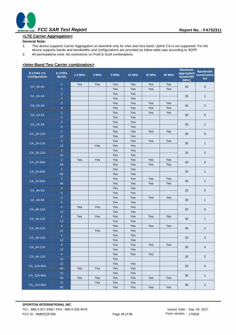
SPORTON INTERNATIONAL INC.
TEL : 886-3-327-3456 / FAX : 886-3-328-4978 Issued Date : Sep. 04, 2017
FCC ID : NM82Q3F300 Page 48 of 89 Form version. : 170509
FCC SAR Test Report Report No. : FA752311
<LTE Carrier Aggregation>
General Note:
1. This device supports Carrier Aggregation on downlink only for inter and intra band, Uplink CA is not supported. For the device supports bands and bandwidths and configurations are provided as follow table was according to 3GPP.
2. All permutations exist. No restrictions on Pcell & Scell combinations.
<Inter-Band Two Carrier combination>
E-UTRA CA Configuration
E-UTRA Bands
1.4 MHz 3 MHz 5 MHz 10 MHz 15 MHz 20 MHz
Maximum aggregated bandwidth
[MHz]
Bandwidth combination
set
CA_2A-4A 2 Yes Yes Yes Yes Yes Yes
40 0 4
Yes Yes Yes Yes
CA_2A-4A 2
Yes Yes
20 1 4
Yes Yes
CA_2A-4A 2
Yes Yes Yes Yes
40 2 4
Yes Yes Yes Yes
CA_2A-5A 2
Yes Yes Yes Yes
30 0 5
Yes Yes
CA_2A-5A 2
Yes Yes
20 1 5
Yes Yes
CA_2A-12A 2
Yes Yes Yes Yes
30 0 12
Yes Yes
CA_2A-12A 2
Yes Yes Yes Yes
30 1 12
Yes Yes Yes
CA_2A-12A 2
Yes Yes
20 2 12
Yes Yes
CA_2A-66A 2 Yes Yes Yes Yes Yes Yes
40 0 66
Yes Yes Yes Yes
CA_2A-66A 2
Yes Yes
20 1 66
Yes Yes
CA_2A-66A 2
Yes Yes Yes Yes
40 2 66
Yes Yes Yes Yes
CA_4A-5A 4
Yes Yes
20 0 5
Yes Yes
CA_4A-5A 4
Yes Yes Yes Yes
30 1 5
Yes Yes
CA_4A-12A 4 Yes Yes Yes Yes
20 0 12
Yes Yes
CA_4A-12A 4 Yes Yes Yes Yes Yes Yes
30 1 12
Yes Yes
CA_4A-12A 4
Yes Yes Yes Yes
30 2 12
Yes Yes Yes
CA_4A-12A 4
Yes Yes
20 3 12
Yes Yes
CA_4A-12A 4
Yes Yes Yes Yes
30 4 12
Yes Yes
CA_4A-12A 4
Yes Yes Yes
20 5 12
Yes
CA_12A-66A 12
Yes Yes
20 0 66 Yes Yes Yes Yes
CA_12A-66A 12
Yes Yes
30 1 66 Yes Yes Yes Yes Yes Yes
CA_12A-66A 12
Yes Yes Yes
30 2 66
Yes Yes Yes Yes
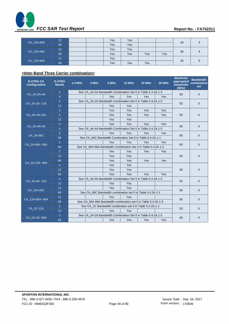
SPORTON INTERNATIONAL INC.
TEL : 886-3-327-3456 / FAX : 886-3-328-4978 Issued Date : Sep. 04, 2017
FCC ID : NM82Q3F300 Page 49 of 89 Form version. : 170509
FCC SAR Test Report Report No. : FA752311
CA_12A-66A 12
Yes Yes
20 3 66
Yes Yes
CA_12A-66A 12
Yes Yes
30 4 66
Yes Yes Yes Yes
CA_12A-66A 12
Yes
20 5 66
Yes Yes Yes
<Inter-Band Three Carrier combination>
E-UTRA CA Configuration
E-UTRA Bands
1.4 MHz 3 MHz 5 MHz 10 MHz 15 MHz 20 MHz
Maximum aggregated bandwidth
[MHz]
Bandwidth combination
set
CA_2A-2A-4A 2 See CA_2A-2A Bandwidth Combination Set 0 in Table 5.4.2A.1-3
60 0 4
Yes Yes Yes Yes
CA_2A-2A- 12A 2 See CA_2A-2A Bandwidth Combination Set 0 in Table 5.4.2A.1-3
50 0 12
Yes Yes
CA_2A-4A-12A
2
Yes Yes Yes Yes
50 0 4
Yes Yes Yes Yes
12
Yes Yes
CA_2A-4A-4A 2
Yes Yes Yes Yes
60 0 4 See CA_4A-4A Bandwidth Combination Set 0 in Table 5.4.2A.1-3
CA_2A-66C 2
Yes Yes Yes Yes
60 0 66 See CA_66C Bandwidth Combination Set 0 in Table 5.4.2A.1-1
CA_2A-66A- 66A 2
Yes Yes Yes Yes
60 0 66 See CA_66A-66A Bandwidth Combination Set 0 in Table 5.4.2A.1-3
CA_2A-12A- 66A
2
Yes Yes Yes Yes
50 0 12
Yes Yes
66
Yes Yes Yes Yes
2
Yes Yes
40 0 12
Yes Yes
66
Yes Yes Yes Yes
CA_4A-4A- 12A 4 See CA_4A-4A Bandwidth Combination Set 0 in Table 5.4.2A.1-3
50 0 12
Yes Yes
CA_12A-66C 12
Yes Yes
50 0 66 See CA_66C Bandwidth combination set 0 in Table 5.4.2A.1-1
CA_12A-66A- 66A 12
Yes Yes
50 0 66 See CA_66A-66A Bandwidth combination set 0 in Table 5.4.2A.1-3
CA_2C-12A 2 See CA_2C Bandwidth combination set 0 in Table 5.4.2A.1-1
50 0 12
Yes Yes
CA_2A-2A- 66A 2 See CA_2A-2A Bandwidth Combination Set 0 in Table 5.4.2A.1-3
60 0 66 Yes Yes Yes Yes
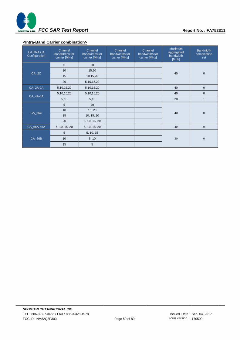
SPORTON INTERNATIONAL INC.
TEL : 886-3-327-3456 / FAX : 886-3-328-4978 Issued Date : Sep. 04, 2017
FCC ID : NM82Q3F300 Page 50 of 89 Form version. : 170509
FCC SAR Test Report Report No. : FA752311
<Intra-Band Carrier combination>
E-UTRA CA Configuration
Channel bandwidths for carrier [MHz]
Channel bandwidths for carrier [MHz]
Channel bandwidths for carrier [MHz]
Channel bandwidths for carrier [MHz]
Maximum aggregated bandwidth
[MHz]
Bandwidth combination
set
CA_2C
5 20
40 0 10 15,20
15 10,15,20
20 5,10,15,20
CA_2A-2A 5,10,15,20 5,10,15,20
40 0
CA_4A-4A 5,10,15,20 5,10,15,20
40 0
5,10 5,10
20 1
CA_66C
5 20
40 0 10 15, 20
15 10, 15, 20
20 5, 10, 15, 20
CA_66A-66A 5, 10, 15, 20 5, 10, 15, 20
40 0
CA_66B
5 5, 10, 15
20 0 10 5, 10
15 5

SPORTON INTERNATIONAL INC.
TEL : 886-3-327-3456 / FAX : 886-3-328-4978 Issued Date : Sep. 04, 2017
FCC ID : NM82Q3F300 Page 51 of 89 Form version. : 170509
FCC SAR Test Report Report No. : FA752311
<LTE Carrier Aggregation Power verification>
General Note:
i. According to KDB941225 D05A v01r02, Uplink maximum output power measurement with downlink carrier aggregation
active should be measured, using the highest output channel measured without downlink carrier aggregation, to confirm
that uplink maximum output power with downlink carrier aggregation active remains within the specified tune-up tolerance
limits and not more than ¼ dB higher than the maximum output measured without downlink carrier aggregation active.
ii. Uplink maximum output power with downlink carrier aggregation active does not show more than ¼ dB higher than the
maximum output power without downlink carrier aggregation active, therefore SAR evaluation with downlink carrier
aggregation active can be excluded.
iii. The device supports downlink carrier aggregation only. Uplink carrier aggregation is not supported. For power
measurement were control and acknowledge data is sent on uplink channels that operate identical to specifications when
downlink carrier aggregation is inactive.
iv. Selected highest measured power when downlink carrier aggregation is inactive for conducted power comparison with
downlink carrier aggregation is active, to confirm that when downlink carrier aggregation is active uplink maximum output
power remains within the specified tune-up tolerance limits and not more than ¼ dB higher than the maximum output power
measured when downlink carrier aggregation inactive.
v. For non-contiguous intra-band CA, the SCC selected to provide maximum separation from the PCC and must remain fully
within the downlink transmission band.
vi. For inter-band CA, the SCC selected highest bandwidth and near the middle of its transmission band.
vii. For Intra-band, contiguous CA, the downlink channels selected to perform the uplink power measurement must satisfy
3GPP channel spacing (5.4.1A of 3GPP TS 36.521 or equivalent) and channel bandwidth (5.4.2A) requirements.
<Maximum output power for Two Carrier power verification>
Configure
PCC SCC Power
LTE Band
BW (MHz)
UL Freq. (MHz)
UL Channel
Mod. UL# RB UL RB Offset
LTE Band
BW (MHz)
DL Freq. (MHz)
DL Channel
With CA Tx.Power
(dBm)
W/O CA Tx.Power
(dBm)
Inter-Band
Band 2 20 1900 19100 QPSK 1 0 Band 4 20 2132.5 2175 22.78 22.80
Band 4 20 1732.5 20175 QPSK 1 0 Band 2 20 1960 900 22.80 22.87
Band 2 20 1900 19100 QPSK 1 0 Band 5 10 881.5 2525 22.76 22.80
Band 5 10 829 20450 QPSK 1 0 Band 2 20 1960 900 22.77 22.82
Band 2 20 1900 19100 QPSK 1 0 Band 12 10 737.5 5095 22.74 22.80
Band 12 10 707.5 23095 QPSK 1 49 Band 2 20 1960 900 22.58 22.59
Band 2 20 1900 19100 QPSK 1 0 Band 66 20 2145 66786 22.72 22.80
Band 66 20 1770 132572 QPSK 1 0 Band 2 20 1960 900 22.89 22.96
Band 4 20 1732.5 20175 QPSK 1 0 Band 5 10 881.5 2525 22.86 22.87
Band 5 10 829 20450 QPSK 1 0 Band 4 20 2132.5 2175 22.77 22.82
Band 4 20 1732.5 20175 QPSK 1 0 Band 12 10 737.5 5095 22.79 22.87
Band 12 10 707.5 23095 QPSK 1 49 Band 4 20 2132.5 2175 22.49 22.59
Band 12 10 707.5 23095 QPSK 1 49 Band 66 20 2145 66786 22.55 22.59
Band 66 20 1770 132572 QPSK 1 0 Band 12 10 737.5 5095 22.91 22.96
Intra-Band
Non-Contiguous
Band 2 20 1900 19100 QPSK 1 0 Band 2 5 1932.5 625 22.72 22.80
Band 4 20 1732.5 20175 QPSK 1 0 Band 4 5 2152.5 2375 22.83 22.87
Band 66 20 1770 132572 QPSK 1 0 Band 66 5 2112.5 66461 22.90 22.96
Contiguous
Band 2 20 1900 19100 QPSK 1 0 Band 2 20 1960.2 902 22.80 22.80
Band 66 20 1770 132572 QPSK 1 0 Band 66 20 2189.8 67234 22.95 22.96
Band 66 5 1777.5 132647 QPSK 1 12 Band 66 15 2168.2 67018 22.93 23.00
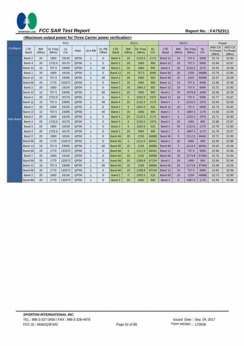
SPORTON INTERNATIONAL INC.
TEL : 886-3-327-3456 / FAX : 886-3-328-4978 Issued Date : Sep. 04, 2017
FCC ID : NM82Q3F300 Page 52 of 89 Form version. : 170509
FCC SAR Test Report Report No. : FA752311
<Maximum output power for Three Carrier power verification>
Configure
PCC SCC1 SCC2 Power
LTE Band
BW (MHz)
UL Freq. (MHz)
UL CH.
Mod. UL# RB UL RB Offset
LTE Band
BW (MHz)
DL Freq. (MHz)
DL CH.
LTE Band
BW (MHz)
DL Freq. (MHz)
DL CH.
With CA Tx.Power
(dBm)
W/O CA Tx.Power
(dBm)
Inter-Band
Band 2 20 1900 19100 QPSK 1 0 Band 4 20 2132.5 2175 Band 12 10 737.5 5095 22.74 22.80
Band 4 20 1732.5 20175 QPSK 1 0 Band 2 20 1960 900 Band 12 10 737.5 5095 22.80 22.87
Band 12 10 707.5 23095 QPSK 1 49 Band 2 20 1960 900 Band 4 20 2132.5 2175 22.54 22.59
Band 2 20 1900 19100 QPSK 1 0 Band 12 10 737.5 5095 Band 66 20 2155 66886 22.75 22.80
Band 12 10 707.5 23095 QPSK 1 49 Band 2 20 1960 900 Band 66 20 2155 66886 22.57 22.59
Band 66 20 1770 132572 QPSK 1 0 Band 2 20 1960 900 Band 12 10 737.5 5095 22.90 22.96
Band 2 20 1900 19100 QPSK 1 0 Band 2 20 1960.2 902 Band 12 10 737.5 5095 22.72 22.80
Band 12 10 707.5 23095 QPSK 1 49 Band 2 20 1960 900 Band 2 20 1979.8 1098 22.56 22.59
Band 4 20 1732.5 20175 QPSK 1 0 Band 4 5 2152.5 2375 Band 12 10 737.5 5095 22.77 22.87
Band 12 10 707.5 23095 QPSK 1 49 Band 4 20 2132.5 2175 Band 4 5 2152.5 2375 22.50 22.59
Band 2 20 1900 19100 QPSK 1 0 Band 2 5 1932.5 625 Band 12 10 737.5 5095 22.73 22.80
Band 12 10 707.5 23095 QPSK 1 49 Band 2 20 1960 900 Band 2 5 1987.5 1175 22.55 22.59
Band 2 20 1900 19100 QPSK 1 0 Band 4 20 2132.5 2175 Band 4 5 2152.5 2375 22.71 22.80
Band 4 20 1732.5 20175 QPSK 1 0 Band 4 5 2152.5 2375 Band 2 20 1960 900 22.80 22.87
Band 2 20 1900 19100 QPSK 1 0 Band 2 5 1932.5 625 Band 4 20 2132.5 2175 22.78 22.80
Band 4 20 1732.5 20175 QPSK 1 0 Band 2 20 1960 900 Band 2 5 1987.5 1175 22.79 22.87
Band 2 20 1900 19100 QPSK 1 0 Band 66 20 2155 66886 Band 66 5 2112.5 66461 22.71 22.80
Band 66 20 1770 132572 QPSK 1 0 Band 66 5 2112.5 66461 Band 2 20 1960 900 22.90 22.96
Band 12 10 707.5 23095 QPSK 1 49 Band 66 20 2155 66886 Band 66 5 2112.5 66461 22.52 22.59
Band 66 20 1770 132572 QPSK 1 0 Band 66 5 2112.5 66461 Band 12 10 737.5 5095 22.96 22.96
Band 2 20 1900 19100 QPSK 1 0 Band 66 20 2155 66886 Band 66 20 2174.8 67084 22.75 22.80
Band 66 20 1770 132572 QPSK 1 0 Band 66 20 2189.8 67234 Band 2 20 1960 900 22.95 22.96
Band 12 10 707.5 23095 QPSK 1 49 Band 66 20 2155 66886 Band 66 20 2174.8 67084 22.58 22.59
Band 66 20 1770 132572 QPSK 1 0 Band 66 20 2189.8 67234 Band 12 10 737.5 5095 22.92 22.96
Band 2 20 1900 19100 QPSK 1 0 Band 2 5 1932.5 625 Band 66 20 2155 66886 22.72 22.80
Band 66 20 1770 132572 QPSK 1 0 Band 2 20 1960 900 Band 2 5 1987.5 1175 22.93 22.96

SPORTON INTERNATIONAL INC.
TEL : 886-3-327-3456 / FAX : 886-3-328-4978 Issued Date : Sep. 04, 2017
FCC ID : NM82Q3F300 Page 53 of 89 Form version. : 170509
FCC SAR Test Report Report No. : FA752311
<WLAN Conducted Power>
General Note:
1. Per KDB 248227 D01v02r02, SAR test reduction is determined according to 802.11 transmission mode configurations and certain exposure conditions with multiple test positions. In the 2.4 GHz band, separate SAR procedures are applied to DSSS and OFDM configurations to simplify DSSS test requirements. For OFDM, in both 2.4 and 5 GHz bands, an initial test configuration must be determined for each standalone and aggregated frequency band, according to the transmission mode configuration with the highest maximum output power specified for production units to perform SAR measurements. If the same highest maximum output power applies to different combinations of channel bandwidths, modulations and data rates, additional procedures are applied to determine which test configurations require SAR measurement. When applicable, an initial test position may be applied to reduce the number of SAR measurements required for next to the ear, UMPC mini-tablet or hotspot mode configurations with multiple test positions.
2. For 2.4 GHz 802.11b DSSS, either the initial test position procedure for multiple exposure test positions or the DSSS procedure for fixed exposure position is applied; these are mutually exclusive. For 2.4 GHz and 5 GHz OFDM configurations, the initial test configuration is applied to measure SAR using either the initial test position procedure for multiple exposure test position configurations or the initial test configuration procedures for fixed exposure test conditions. Based on the reported SAR of the measured configurations and maximum output power of the transmission mode configurations that are not included in the initial test configuration, the subsequent test configuration and initial test position procedures are applied to determine if SAR measurements are required for the remaining OFDM transmission configurations. In general, the number of test channels that require SAR measurement is minimized based on maximum output power measured for the test sample(s).
3. For OFDM transmission configurations in the 2.4 GHz and 5 GHz bands, When the same maximum power is specified for multiple transmission modes in a frequency band, the largest channel bandwidth, lowest order modulation, lowest data rate and lowest order 802.11a/g/n/ac mode is used for SAR measurement, on the highest measured output power channel for each frequency band.
4. DSSS and OFDM configurations are considered separately according to the required SAR procedures. SAR is measured in the initial test position using the 802.11 transmission mode configuration required by the DSSS procedure or initial test configuration and subsequent test configuration(s) according to the OFDM procedures.18 The initial test position procedure is described in the following:
a. When the reported SAR of the initial test position is ≤ 0.4 W/kg, further SAR measurement is not required for the other test positions in that exposure configuration and 802.11 transmission mode combinations within the frequency band or aggregated band.
b. When the reported SAR of the test position is > 0.4 W/kg, SAR is repeated for the 802.11 transmission mode configuration tested in the initial test position to measure the subsequent next closet/smallest test separation distance and maximum coupling test position on the highest maximum output power channel, until the report SAR is ≤ 0.8 W/kg or all required test position are tested.
c. For all positions/configurations, when the reported SAR is > 0.8 W/kg, SAR is measured for these test positions/configurations on the subsequent next highest measured output power channel(s) until the reported SAR is ≤ 1.2 W/kg or all required channels are tested.

SPORTON INTERNATIONAL INC.
TEL : 886-3-327-3456 / FAX : 886-3-328-4978 Issued Date : Sep. 04, 2017
FCC ID : NM82Q3F300 Page 54 of 89 Form version. : 170509
FCC SAR Test Report Report No. : FA752311
<2.4GHz WLAN>
2.4GHz WLAN
Mode Channel Frequency
(MHz) Average power
(dBm) Tune-Up
Limit Duty Cycle %
802.11b 1Mbps
1 2412 18.10 19.00
100.00 6 2437 17.03 19.00
11 2462 18.01 19.00
802.11g 6Mbps
1 2412 15.84 18.50
93.43 6 2437 15.96 18.50
11 2462 15.97 18.50
802.11n-HT20 MCS0
1 2412 15.87 18.50
93.02 6 2437 15.98 18.50
11 2462 15.99 18.50
802.11n-HT40 MCS0
3 2422 15.70 18.00
87.41 6 2437 15.88 18.00
9 2452 15.63 18.00
<5GHz WLAN>
5.2GHz WLAN
Mode Channel Frequency
(MHz) Average power
(dBm) Tune-Up
Limit Duty Cycle %
802.11a 6Mbps
36 5180 15.94 18.50
93.48 40 5200 15.85 18.50
44 5220 15.79 18.50
48 5240 15.77 18.50
802.11n-HT20 MCS0
36 5180 15.97 18.50
93.41 40 5200 15.90 18.50
44 5220 15.85 18.50
48 5240 15.80 18.50
802.11n-HT40 MCS0 38 5190 15.78 18.50
87.41 46 5230 15.98 18.50
802.11ac-VHT20 MCS0
36 5180 15.95 18.50
93.80 40 5200 15.88 18.50
44 5220 15.83 18.50
48 5240 15.78 18.50
802.11ac-VHT40 MCS0
38 5190 15.73 18.50 89.47
46 5230 15.96 18.50
802.11ac-VHT80 MCS0
42 5210 16.53 18.50 85.19
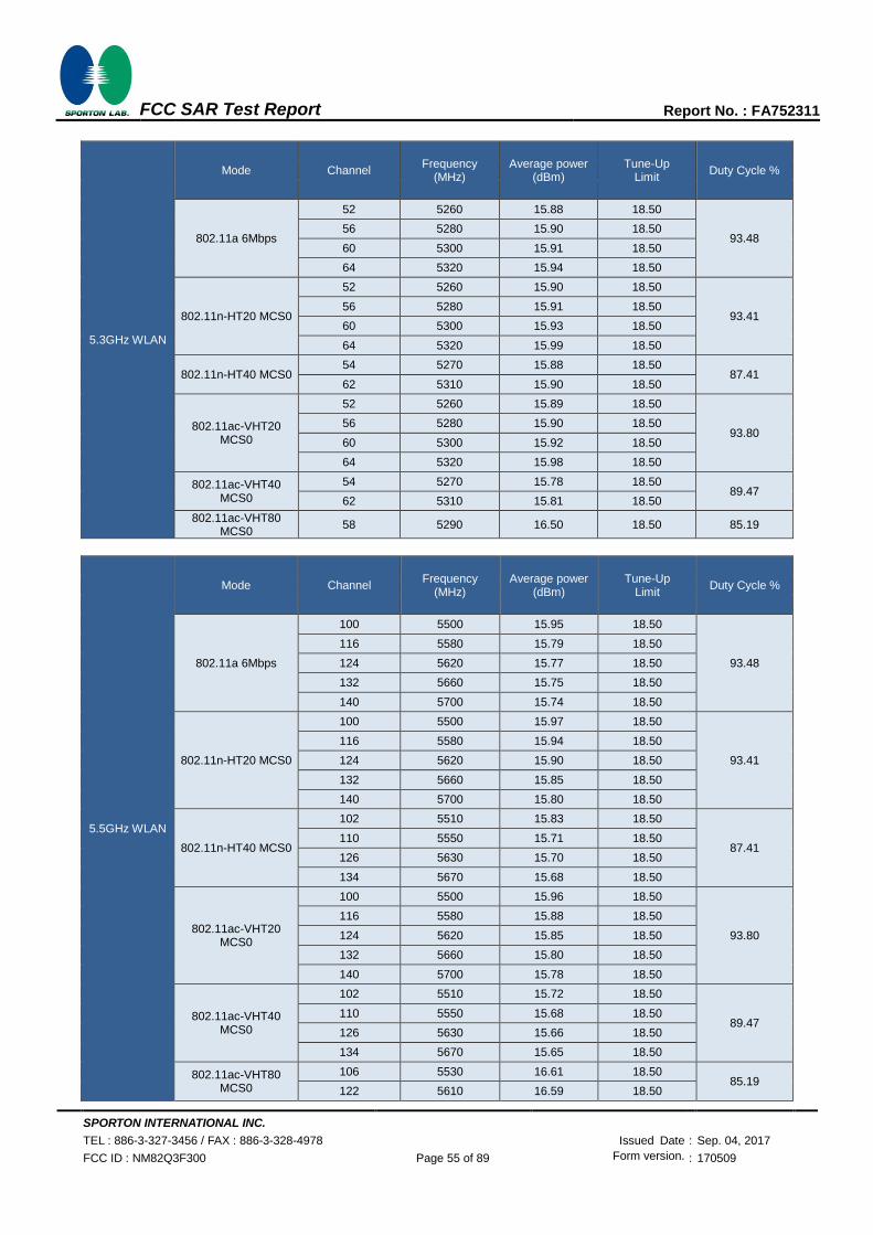
SPORTON INTERNATIONAL INC.
TEL : 886-3-327-3456 / FAX : 886-3-328-4978 Issued Date : Sep. 04, 2017
FCC ID : NM82Q3F300 Page 55 of 89 Form version. : 170509
FCC SAR Test Report Report No. : FA752311
5.3GHz WLAN
Mode Channel Frequency
(MHz) Average power
(dBm) Tune-Up
Limit Duty Cycle %
802.11a 6Mbps
52 5260 15.88 18.50
93.48 56 5280 15.90 18.50
60 5300 15.91 18.50
64 5320 15.94 18.50
802.11n-HT20 MCS0
52 5260 15.90 18.50
93.41 56 5280 15.91 18.50
60 5300 15.93 18.50
64 5320 15.99 18.50
802.11n-HT40 MCS0 54 5270 15.88 18.50
87.41 62 5310 15.90 18.50
802.11ac-VHT20 MCS0
52 5260 15.89 18.50
93.80 56 5280 15.90 18.50
60 5300 15.92 18.50
64 5320 15.98 18.50
802.11ac-VHT40 MCS0
54 5270 15.78 18.50 89.47
62 5310 15.81 18.50
802.11ac-VHT80 MCS0
58 5290 16.50 18.50 85.19
5.5GHz WLAN
Mode Channel Frequency
(MHz) Average power
(dBm) Tune-Up
Limit Duty Cycle %
802.11a 6Mbps
100 5500 15.95 18.50
93.48
116 5580 15.79 18.50
124 5620 15.77 18.50
132 5660 15.75 18.50
140 5700 15.74 18.50
802.11n-HT20 MCS0
100 5500 15.97 18.50
93.41
116 5580 15.94 18.50
124 5620 15.90 18.50
132 5660 15.85 18.50
140 5700 15.80 18.50
802.11n-HT40 MCS0
102 5510 15.83 18.50
87.41 110 5550 15.71 18.50
126 5630 15.70 18.50
134 5670 15.68 18.50
802.11ac-VHT20 MCS0
100 5500 15.96 18.50
93.80
116 5580 15.88 18.50
124 5620 15.85 18.50
132 5660 15.80 18.50
140 5700 15.78 18.50
802.11ac-VHT40 MCS0
102 5510 15.72 18.50
89.47 110 5550 15.68 18.50
126 5630 15.66 18.50
134 5670 15.65 18.50
802.11ac-VHT80 MCS0
106 5530 16.61 18.50 85.19
122 5610 16.59 18.50

SPORTON INTERNATIONAL INC.
TEL : 886-3-327-3456 / FAX : 886-3-328-4978 Issued Date : Sep. 04, 2017
FCC ID : NM82Q3F300 Page 56 of 89 Form version. : 170509
FCC SAR Test Report Report No. : FA752311
5.8GHz WLAN
Mode Channel Frequency
(MHz) Average power
(dBm) Tune-Up
Limit Duty Cycle %
802.11a MCS0
149 5745 15.97 18.50
93.48 157 5785 15.96 18.50
165 5825 15.95 18.50
802.11n-HT20 MCS0
149 5745 15.99 18.50
93.41 157 5785 15.98 18.50
165 5825 15.97 18.50
802.11n-HT40 MCS0 151 5755 15.98 18.50
87.41 159 5795 15.99 18.50
802.11ac-VHT20 MCS0
149 5745 15.98 18.50
93.80 157 5785 15.97 18.50
165 5825 15.96 18.50
802.11ac-VHT40 MCS0
151 5755 15.91 18.50 89.47
159 5795 15.98 18.50
802.11ac-VHT80 MCS0
155 5775 16.52 18.50 85.19
<2.4GHz Bluetooth>
Mode Channel Frequency
(MHz)
Average power (dBm)
1Mbps 2Mbps 3Mbps
BR / EDR
CH 00 2402 7.34 4.92 5.05
CH 39 2441 5.64 2.54 2.50
CH 78 2480 6.81 4.49 4.48
Tune-up Limit 7.5 5.5 5.5
Mode Channel Frequency
(MHz)
Average power (dBm)
GFSK
LE
CH 00 2402 2.91
CH 19 2440 0.83
CH 39 2480 3.29
Tune-up Limit 3.5
Mode Channel Frequency
(MHz)
Average power (dBm)
GFSK
BT5.0
CH 00 2402 1.28
CH 19 2440 -1.11
CH 39 2480 1.24
Tune-up Limit 1.5
General Note:
1. For 2.4GHz Bluetooth SAR testing was selected 1Mbps, due to its highest average power.
2. The Bluetooth duty cycle is 77.13%, according to 2016 Oct. TCB workshop for Bluetooth SAR scaling need further consideration and the theoretical duty cycle is 83.3%, therefore the actual duty cycle will be scaled up to the theoretical value of Bluetooth reported SAR calculation

SPORTON INTERNATIONAL INC.
TEL : 886-3-327-3456 / FAX : 886-3-328-4978 Issued Date : Sep. 04, 2017
FCC ID : NM82Q3F300 Page 57 of 89 Form version. : 170509
FCC SAR Test Report Report No. : FA752311
13. Exclusions Applied
<2.4GHz ANT+>
Max Average power(dBm)
ANT+ GFSK
-6
Note:
1. Per KDB 447498 D01v06, the 1-g and 10-g SAR test exclusion thresholds for 100 MHz to 6 GHz at test separation distances ≤ 50 mm are determined by:
[(max. power of channel, including tune-up tolerance, mW)/(min. test separation distance, mm)] ·[√f(GHz)] ≤ 3.0 for 1-g SAR and ≤ 7.5 for 10-g extremity SAR
‧ f(GHz) is the RF channel transmit frequency in GHz ‧ Power and distance are rounded to the nearest mW and mm before calculation ‧ The result is rounded to one decimal place for comparison
ANT+ Max Power (dBm) Separation Distance (mm) Frequency (GHz) exclusion thresholds
-6 < 5 2.48 0.00
Note:
Per KDB 447498 D01v06, when the minimum test separation distance is < 5 mm, a distance of 5 mm is applied to determine SAR test exclusion. The test exclusion threshold is 0 which is <= 3, SAR testing is not required.
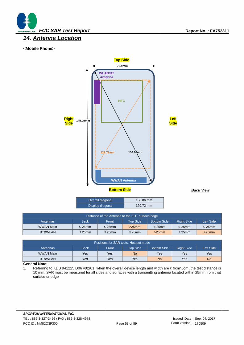
SPORTON INTERNATIONAL INC.
TEL : 886-3-327-3456 / FAX : 886-3-328-4978 Issued Date : Sep. 04, 2017
FCC ID : NM82Q3F300 Page 58 of 89 Form version. : 170509
FCC SAR Test Report Report No. : FA752311
14. Antenna Location
<Mobile Phone>
Overall diagonal 156.86 mm
Display diagonal 129.72 mm
Distance of the Antenna to the EUT surface/edge
Antennas Back Front Top Side Bottom Side Right Side Left Side
WWAN Main ≤ 25mm ≤ 25mm >25mm ≤ 25mm ≤ 25mm ≤ 25mm
BT&WLAN ≤ 25mm ≤ 25mm ≤ 25mm >25mm ≤ 25mm >25mm
Positions for SAR tests; Hotspot mode
Antennas Back Front Top Side Bottom Side Right Side Left Side
WWAN Main Yes Yes No Yes Yes Yes
BT&WLAN Yes Yes Yes No Yes No
General Note:
1. Referring to KDB 941225 D06 v02r01, when the overall device length and width are ≥ 9cm*5cm, the test distance is 10 mm. SAR must be measured for all sides and surfaces with a transmitting antenna located within 25mm from that surface or edge
Top Side
Right
Side
Bottom Side Back View
Left Side
WWAN Antenna
WLAN/BT
Antenna
149.09mm
72.9mm
156.86mm 129.72mm
NFC

SPORTON INTERNATIONAL INC.
TEL : 886-3-327-3456 / FAX : 886-3-328-4978 Issued Date : Sep. 04, 2017
FCC ID : NM82Q3F300 Page 59 of 89 Form version. : 170509
FCC SAR Test Report Report No. : FA752311
15. SAR Test Results
General Note:
1. Per KDB 447498 D01v06, the reported SAR is the measured SAR value adjusted for maximum tune-up tolerance.
a. Tune-up scaling Factor = tune-up limit power (mW) / EUT RF power (mW), where tune-up limit is the maximum rated
power among all production units.
b. For SAR testing of WLAN signal with non-100% duty cycle, the measured SAR is scaled-up by the duty cycle scaling
factor which is equal to "1/(duty cycle)"
c. For WWAN: Reported SAR(W/kg)= Measured SAR(W/kg)*Tune-up Scaling Factor
d. For WLAN/Bluetooth: Reported SAR(W/kg)= Measured SAR(W/kg)* Duty Cycle scaling factor * Tune-up scaling factor
2. Per KDB 447498 D01v06, for each exposure position, testing of other required channels within the operating mode of a
frequency band is not required when the reported 1-g or 10-g SAR for the mid-band or highest output power channel is:
‧ ≤ 0.8 W/kg or 2.0 W/kg, for 1-g or 10-g respectively, when the transmission band is ≤ 100 MHz
‧ ≤ 0.6 W/kg or 1.5 W/kg, for 1-g or 10-g respectively, when the transmission band is between 100 MHz and 200 MHz
‧ ≤ 0.4 W/kg or 1.0 W/kg, for 1-g or 10-g respectively, when the transmission band is ≥ 200 MHz
3. Per KDB 865664 D01v01r04, for each frequency band, repeated SAR measurement is required only when the measured
SAR is ≥0.8W/kg.
4. Per KDB 648474 D04v01r03, when the reported SAR for a body-worn accessory measured without a headset connected to
the handset is ≤ 1.2 W/kg, SAR testing with a headset connected to the handset is not required.
GSM Note:
1. Per KDB 941225 D01v03r01, for SAR test reduction for GSM / GPRS / EDGE modes is determined by the source-based
time-averaged output power including tune-up tolerance. The mode with highest specified time-averaged output power
should be tested for SAR compliance in the applicable exposure conditions. For modes with the same specified maximum
output power and tolerance, the higher number time-slot configuration should be tested. Therefore, the GPRS (4Tx slots) for
GSM850/GSM1900 is considered as the primary mode.
2. Other configurations of GSM / GPRS / EDGE are considered as secondary modes. The 3G SAR test reduction procedure is
applied, when the maximum output power and tune-up tolerance specified for production units in a secondary mode is ≤ ¼
dB higher than the primary mode, SAR measurement is not required for the secondary mode.
UMTS Note:
1. Per KDB 941225 D01v03r01, for SAR testing is measured using a 12.2 kbps RMC with TPC bits configured to all “1’s”.
2. Per KDB 941225 D01v03r01, RMC 12.2kbps setting is used to evaluate SAR. The maximum output power and tune-up
tolerance specified for production units in HSDPA / HSUPA / DC-HSDPA is ≤ ¼ dB higher than RMC 12.2Kbps or when the
highest reported SAR of the RMC12.2Kbps is scaled by the ratio of specified maximum output power and tune-up tolerance
of HSDPA / HSUPA / DC-HSDPA to RMC12.2Kbps and the adjusted SAR is ≤ 1.2 W/kg, SAR measurement is not required
for HSDPA / HSUPA / DC-HSDPA, and according to the following RF output power, the output power results of the
secondary modes (HSUPA, HSDPA, DC-HSDPA) are less than ¼ dB higher than the primary modes; therefore, SAR
measurement is not required for HSDPA / HSUPA / DC-HSDPA.
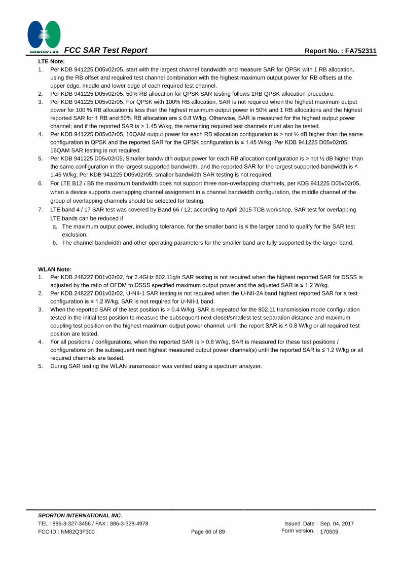
SPORTON INTERNATIONAL INC.
TEL : 886-3-327-3456 / FAX : 886-3-328-4978 Issued Date : Sep. 04, 2017
FCC ID : NM82Q3F300 Page 60 of 89 Form version. : 170509
FCC SAR Test Report Report No. : FA752311
LTE Note:
1. Per KDB 941225 D05v02r05, start with the largest channel bandwidth and measure SAR for QPSK with 1 RB allocation,
using the RB offset and required test channel combination with the highest maximum output power for RB offsets at the
upper edge, middle and lower edge of each required test channel.
2. Per KDB 941225 D05v02r05, 50% RB allocation for QPSK SAR testing follows 1RB QPSK allocation procedure.
3. Per KDB 941225 D05v02r05, For QPSK with 100% RB allocation, SAR is not required when the highest maximum output
power for 100 % RB allocation is less than the highest maximum output power in 50% and 1 RB allocations and the highest
reported SAR for 1 RB and 50% RB allocation are ≤ 0.8 W/kg. Otherwise, SAR is measured for the highest output power
channel; and if the reported SAR is > 1.45 W/kg, the remaining required test channels must also be tested.
4. Per KDB 941225 D05v02r05, 16QAM output power for each RB allocation configuration is > not ½ dB higher than the same
configuration in QPSK and the reported SAR for the QPSK configuration is ≤ 1.45 W/kg; Per KDB 941225 D05v02r05,
16QAM SAR testing is not required.
5. Per KDB 941225 D05v02r05, Smaller bandwidth output power for each RB allocation configuration is > not ½ dB higher than
the same configuration in the largest supported bandwidth, and the reported SAR for the largest supported bandwidth is ≤
1.45 W/kg; Per KDB 941225 D05v02r05, smaller bandwidth SAR testing is not required.
6. For LTE B12 / B5 the maximum bandwidth does not support three non-overlapping channels, per KDB 941225 D05v02r05,
when a device supports overlapping channel assignment in a channel bandwidth configuration, the middle channel of the
group of overlapping channels should be selected for testing.
7. LTE band 4 / 17 SAR test was covered by Band 66 / 12; according to April 2015 TCB workshop, SAR test for overlapping
LTE bands can be reduced if
a. The maximum output power, including tolerance, for the smaller band is ≤ the larger band to qualify for the SAR test
exclusion.
b. The channel bandwidth and other operating parameters for the smaller band are fully supported by the larger band.
WLAN Note:
1. Per KDB 248227 D01v02r02, for 2.4GHz 802.11g/n SAR testing is not required when the highest reported SAR for DSSS is
adjusted by the ratio of OFDM to DSSS specified maximum output power and the adjusted SAR is ≤ 1.2 W/kg.
2. Per KDB 248227 D01v02r02, U-NII-1 SAR testing is not required when the U-NII-2A band highest reported SAR for a test
configuration is ≤ 1.2 W/kg, SAR is not required for U-NII-1 band.
3. When the reported SAR of the test position is > 0.4 W/kg, SAR is repeated for the 802.11 transmission mode configuration
tested in the initial test position to measure the subsequent next closet/smallest test separation distance and maximum
coupling test position on the highest maximum output power channel, until the report SAR is ≤ 0.8 W/kg or all required test
position are tested.
4. For all positions / configurations, when the reported SAR is > 0.8 W/kg, SAR is measured for these test positions /
configurations on the subsequent next highest measured output power channel(s) until the reported SAR is ≤ 1.2 W/kg or all
required channels are tested.
5. During SAR testing the WLAN transmission was verified using a spectrum analyzer.

SPORTON INTERNATIONAL INC.
TEL : 886-3-327-3456 / FAX : 886-3-328-4978 Issued Date : Sep. 04, 2017
FCC ID : NM82Q3F300 Page 61 of 89 Form version. : 170509
FCC SAR Test Report Report No. : FA752311
15.1 Head SAR
<GSM SAR>
Plot No.
Band Mode Test
Position Gap (mm)
Sample Battery Ch. Freq. (MHz)
Average Power (dBm)
Tune-Up Limit (dBm)
Tune-up Scaling Factor
Power Drift (dB)
Measured 1g SAR (W/kg)
Reported 1g SAR (W/kg)
GSM850 GPRS(4 Tx slots) Right Cheek 0mm 1 1 128 824.2 29.73 30.00 1.064 0.03 0.084 0.089
GSM850 GPRS(4 Tx slots) Right Tilted 0mm 1 1 128 824.2 29.73 30.00 1.064 0.12 0.052 0.055
GSM850 GPRS(4 Tx slots) Left Cheek 0mm 1 1 128 824.2 29.73 30.00 1.064 0.05 0.090 0.096
GSM850 GPRS(4 Tx slots) Left Cheek 0mm 1 1 189 836.4 29.37 30.00 1.156 0.05 0.117 0.135
01 GSM850 GPRS(4 Tx slots) Left Cheek 0mm 1 1 251 848.8 29.35 30.00 1.161 0.04 0.140 0.163
GSM850 GPRS(4 Tx slots) Left Cheek 0mm 2 2 251 848.8 29.35 30.00 1.161 -0.09 0.104 0.121
GSM850 GPRS(4 Tx slots) Left Tilted 0mm 1 1 128 824.2 29.73 30.00 1.064 0.07 0.037 0.039
GSM850 GPRS (4 Tx slots) Right Cheek 0mm 3 1 128 824.2 29.73 30.00 1.064 -0.12 0.104 0.111
GSM850 GPRS (4 Tx slots) Right Cheek 0mm 3 1 189 836.4 29.37 30.00 1.156 0.12 0.107 0.124
GSM850 GPRS (4 Tx slots) Right Cheek 0mm 3 1 251 848.8 29.35 30.00 1.161 -0.03 0.132 0.153
GSM850 GPRS (4 Tx slots) Right Tilted 0mm 3 1 128 824.2 29.73 30.00 1.064 0.12 0.061 0.065
GSM850 GPRS (4 Tx slots) Left Cheek 0mm 3 1 128 824.2 29.73 30.00 1.064 0.11 0.097 0.103
GSM850 GPRS (4 Tx slots) Left Tilted 0mm 3 1 128 824.2 29.73 30.00 1.064 0.12 0.064 0.068
GSM850 GPRS (4 Tx slots) Right Cheek 0mm 3 1 128 824.2 29.73 30.00 1.064 -0.12 0.104 0.111
GSM1900 GPRS(4 Tx slots) Right Cheek 0mm 1 1 810 1909.8 27.57 28.00 1.104 0.02 0.114 0.126
GSM1900 GPRS(4 Tx slots) Right Tilted 0mm 1 1 810 1909.8 27.57 28.00 1.104 0.09 0.056 0.062
GSM1900 GPRS(4 Tx slots) Left Cheek 0mm 1 1 810 1909.8 27.57 28.00 1.104 -0.06 0.281 0.310
02 GSM1900 GPRS(4 Tx slots) Left Cheek 0mm 1 1 512 1850.2 27.53 28.00 1.114 -0.04 0.318 0.354
GSM1900 GPRS(4 Tx slots) Left Cheek 0mm 1 2 512 1850.2 27.53 28.00 1.114 0 0.184 0.205
GSM1900 GPRS(4 Tx slots) Left Cheek 0mm 1 1 661 1880 27.54 28.00 1.112 0.12 0.285 0.317
GSM1900 GPRS(4 Tx slots) Left Tilted 0mm 1 1 810 1909.8 27.57 28.00 1.104 0.17 0.078 0.086
GSM1900 GPRS(4 Tx slots) Right Cheek 0mm 3 1 810 1909.8 27.57 28.00 1.104 0.05 0.053 0.059
GSM1900 GPRS(4 Tx slots) Right Tilted 0mm 3 1 810 1909.8 27.57 28.00 1.104 -0.18 0.032 0.035
GSM1900 GPRS(4 Tx slots) Left Cheek 0mm 3 1 810 1909.8 27.57 28.00 1.104 0.14 0.080 0.088
GSM1900 GPRS(4 Tx slots) Left Cheek 0mm 3 1 512 1850.2 27.53 28.00 1.114 0.18 0.132 0.147
GSM1900 GPRS(4 Tx slots) Left Cheek 0mm 3 1 661 1909.8 27.54 28.00 1.112 0.18 0.124 0.138
GSM1900 GPRS(4 Tx slots) Left Tilted 0mm 3 1 810 1909.8 27.57 28.00 1.104 -0.01 0.033 0.036
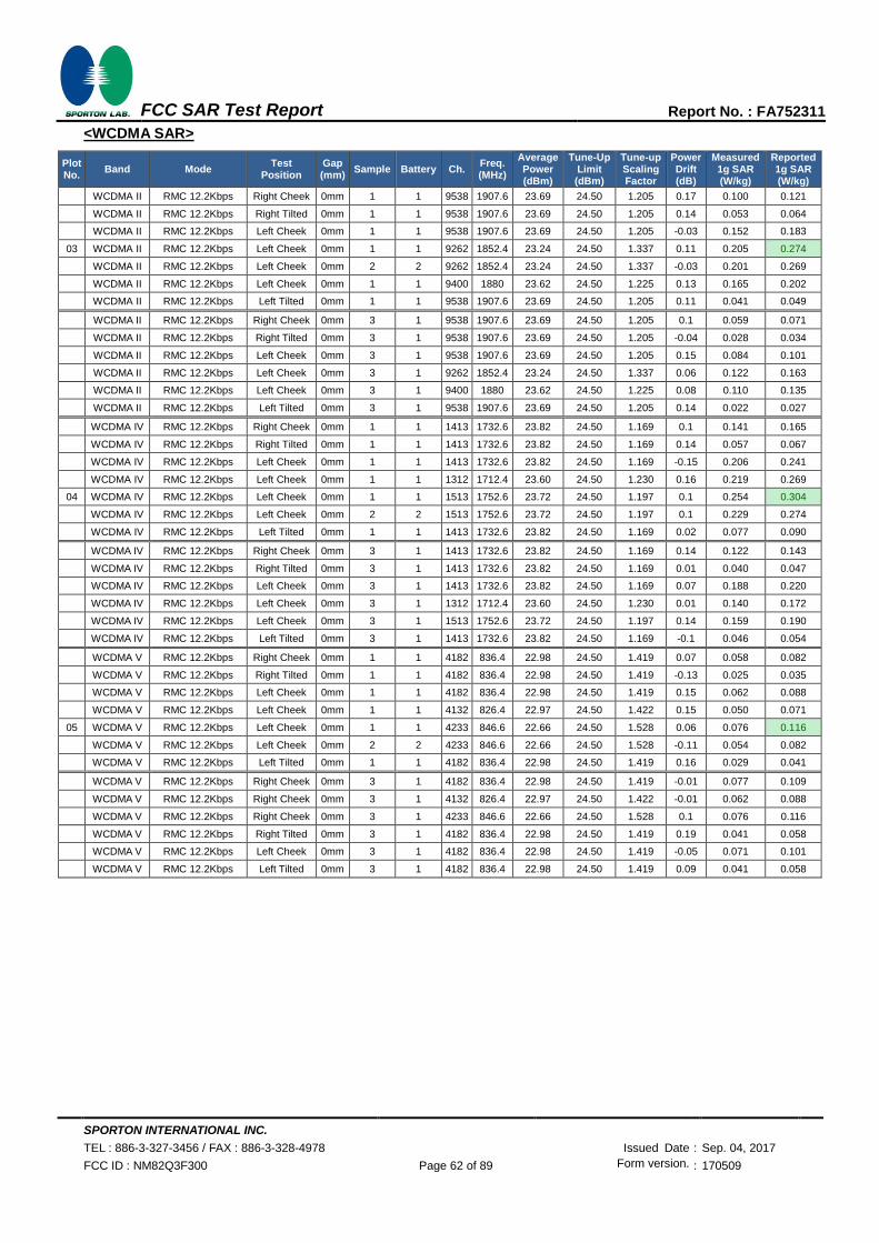
SPORTON INTERNATIONAL INC.
TEL : 886-3-327-3456 / FAX : 886-3-328-4978 Issued Date : Sep. 04, 2017
FCC ID : NM82Q3F300 Page 62 of 89 Form version. : 170509
FCC SAR Test Report Report No. : FA752311
<WCDMA SAR>
Plot No.
Band Mode Test
Position Gap (mm)
Sample Battery Ch. Freq. (MHz)
Average Power (dBm)
Tune-Up Limit (dBm)
Tune-up Scaling Factor
Power Drift (dB)
Measured 1g SAR (W/kg)
Reported 1g SAR (W/kg)
WCDMA II RMC 12.2Kbps Right Cheek 0mm 1 1 9538 1907.6 23.69 24.50 1.205 0.17 0.100 0.121
WCDMA II RMC 12.2Kbps Right Tilted 0mm 1 1 9538 1907.6 23.69 24.50 1.205 0.14 0.053 0.064
WCDMA II RMC 12.2Kbps Left Cheek 0mm 1 1 9538 1907.6 23.69 24.50 1.205 -0.03 0.152 0.183
03 WCDMA II RMC 12.2Kbps Left Cheek 0mm 1 1 9262 1852.4 23.24 24.50 1.337 0.11 0.205 0.274
WCDMA II RMC 12.2Kbps Left Cheek 0mm 2 2 9262 1852.4 23.24 24.50 1.337 -0.03 0.201 0.269
WCDMA II RMC 12.2Kbps Left Cheek 0mm 1 1 9400 1880 23.62 24.50 1.225 0.13 0.165 0.202
WCDMA II RMC 12.2Kbps Left Tilted 0mm 1 1 9538 1907.6 23.69 24.50 1.205 0.11 0.041 0.049
WCDMA II RMC 12.2Kbps Right Cheek 0mm 3 1 9538 1907.6 23.69 24.50 1.205 0.1 0.059 0.071
WCDMA II RMC 12.2Kbps Right Tilted 0mm 3 1 9538 1907.6 23.69 24.50 1.205 -0.04 0.028 0.034
WCDMA II RMC 12.2Kbps Left Cheek 0mm 3 1 9538 1907.6 23.69 24.50 1.205 0.15 0.084 0.101
WCDMA II RMC 12.2Kbps Left Cheek 0mm 3 1 9262 1852.4 23.24 24.50 1.337 0.06 0.122 0.163
WCDMA II RMC 12.2Kbps Left Cheek 0mm 3 1 9400 1880 23.62 24.50 1.225 0.08 0.110 0.135
WCDMA II RMC 12.2Kbps Left Tilted 0mm 3 1 9538 1907.6 23.69 24.50 1.205 0.14 0.022 0.027
WCDMA IV RMC 12.2Kbps Right Cheek 0mm 1 1 1413 1732.6 23.82 24.50 1.169 0.1 0.141 0.165
WCDMA IV RMC 12.2Kbps Right Tilted 0mm 1 1 1413 1732.6 23.82 24.50 1.169 0.14 0.057 0.067
WCDMA IV RMC 12.2Kbps Left Cheek 0mm 1 1 1413 1732.6 23.82 24.50 1.169 -0.15 0.206 0.241
WCDMA IV RMC 12.2Kbps Left Cheek 0mm 1 1 1312 1712.4 23.60 24.50 1.230 0.16 0.219 0.269
04 WCDMA IV RMC 12.2Kbps Left Cheek 0mm 1 1 1513 1752.6 23.72 24.50 1.197 0.1 0.254 0.304
WCDMA IV RMC 12.2Kbps Left Cheek 0mm 2 2 1513 1752.6 23.72 24.50 1.197 0.1 0.229 0.274
WCDMA IV RMC 12.2Kbps Left Tilted 0mm 1 1 1413 1732.6 23.82 24.50 1.169 0.02 0.077 0.090
WCDMA IV RMC 12.2Kbps Right Cheek 0mm 3 1 1413 1732.6 23.82 24.50 1.169 0.14 0.122 0.143
WCDMA IV RMC 12.2Kbps Right Tilted 0mm 3 1 1413 1732.6 23.82 24.50 1.169 0.01 0.040 0.047
WCDMA IV RMC 12.2Kbps Left Cheek 0mm 3 1 1413 1732.6 23.82 24.50 1.169 0.07 0.188 0.220
WCDMA IV RMC 12.2Kbps Left Cheek 0mm 3 1 1312 1712.4 23.60 24.50 1.230 0.01 0.140 0.172
WCDMA IV RMC 12.2Kbps Left Cheek 0mm 3 1 1513 1752.6 23.72 24.50 1.197 0.14 0.159 0.190
WCDMA IV RMC 12.2Kbps Left Tilted 0mm 3 1 1413 1732.6 23.82 24.50 1.169 -0.1 0.046 0.054
WCDMA V RMC 12.2Kbps Right Cheek 0mm 1 1 4182 836.4 22.98 24.50 1.419 0.07 0.058 0.082
WCDMA V RMC 12.2Kbps Right Tilted 0mm 1 1 4182 836.4 22.98 24.50 1.419 -0.13 0.025 0.035
WCDMA V RMC 12.2Kbps Left Cheek 0mm 1 1 4182 836.4 22.98 24.50 1.419 0.15 0.062 0.088
WCDMA V RMC 12.2Kbps Left Cheek 0mm 1 1 4132 826.4 22.97 24.50 1.422 0.15 0.050 0.071
05 WCDMA V RMC 12.2Kbps Left Cheek 0mm 1 1 4233 846.6 22.66 24.50 1.528 0.06 0.076 0.116
WCDMA V RMC 12.2Kbps Left Cheek 0mm 2 2 4233 846.6 22.66 24.50 1.528 -0.11 0.054 0.082
WCDMA V RMC 12.2Kbps Left Tilted 0mm 1 1 4182 836.4 22.98 24.50 1.419 0.16 0.029 0.041
WCDMA V RMC 12.2Kbps Right Cheek 0mm 3 1 4182 836.4 22.98 24.50 1.419 -0.01 0.077 0.109
WCDMA V RMC 12.2Kbps Right Cheek 0mm 3 1 4132 826.4 22.97 24.50 1.422 -0.01 0.062 0.088
WCDMA V RMC 12.2Kbps Right Cheek 0mm 3 1 4233 846.6 22.66 24.50 1.528 0.1 0.076 0.116
WCDMA V RMC 12.2Kbps Right Tilted 0mm 3 1 4182 836.4 22.98 24.50 1.419 0.19 0.041 0.058
WCDMA V RMC 12.2Kbps Left Cheek 0mm 3 1 4182 836.4 22.98 24.50 1.419 -0.05 0.071 0.101
WCDMA V RMC 12.2Kbps Left Tilted 0mm 3 1 4182 836.4 22.98 24.50 1.419 0.09 0.041 0.058
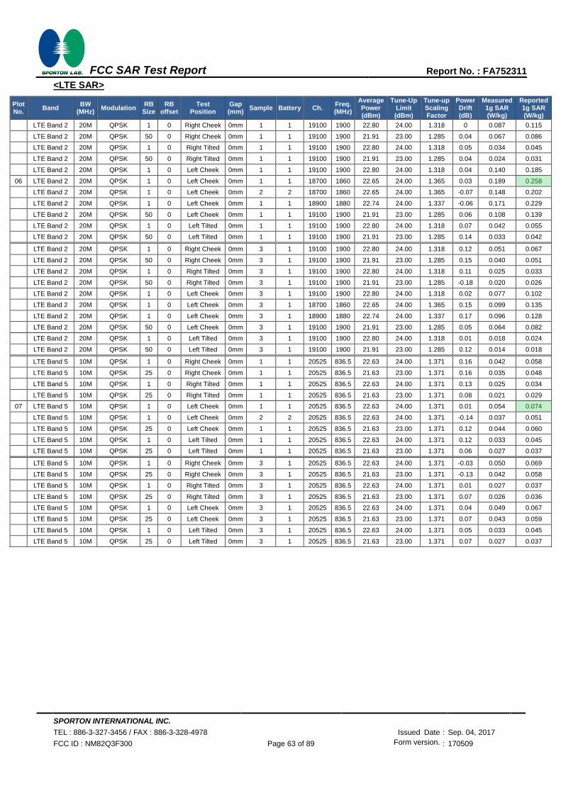
SPORTON INTERNATIONAL INC.
TEL : 886-3-327-3456 / FAX : 886-3-328-4978 Issued Date : Sep. 04, 2017
FCC ID : NM82Q3F300 Page 63 of 89 Form version. : 170509
FCC SAR Test Report Report No. : FA752311
<LTE SAR>
Plot No.
Band BW
(MHz) Modulation
RB Size
RB offset
Test Position
Gap (mm)
Sample Battery Ch. Freq. (MHz)
Average Power (dBm)
Tune-Up Limit (dBm)
Tune-up Scaling Factor
Power Drift (dB)
Measured 1g SAR (W/kg)
Reported 1g SAR (W/kg)
LTE Band 2 20M QPSK 1 0 Right Cheek 0mm 1 1 19100 1900 22.80 24.00 1.318 0 0.087 0.115
LTE Band 2 20M QPSK 50 0 Right Cheek 0mm 1 1 19100 1900 21.91 23.00 1.285 0.04 0.067 0.086
LTE Band 2 20M QPSK 1 0 Right Tilted 0mm 1 1 19100 1900 22.80 24.00 1.318 0.05 0.034 0.045
LTE Band 2 20M QPSK 50 0 Right Tilted 0mm 1 1 19100 1900 21.91 23.00 1.285 0.04 0.024 0.031
LTE Band 2 20M QPSK 1 0 Left Cheek 0mm 1 1 19100 1900 22.80 24.00 1.318 0.04 0.140 0.185
06 LTE Band 2 20M QPSK 1 0 Left Cheek 0mm 1 1 18700 1860 22.65 24.00 1.365 0.03 0.189 0.258
LTE Band 2 20M QPSK 1 0 Left Cheek 0mm 2 2 18700 1860 22.65 24.00 1.365 -0.07 0.148 0.202
LTE Band 2 20M QPSK 1 0 Left Cheek 0mm 1 1 18900 1880 22.74 24.00 1.337 -0.06 0.171 0.229
LTE Band 2 20M QPSK 50 0 Left Cheek 0mm 1 1 19100 1900 21.91 23.00 1.285 0.06 0.108 0.139
LTE Band 2 20M QPSK 1 0 Left Tilted 0mm 1 1 19100 1900 22.80 24.00 1.318 0.07 0.042 0.055
LTE Band 2 20M QPSK 50 0 Left Tilted 0mm 1 1 19100 1900 21.91 23.00 1.285 0.14 0.033 0.042
LTE Band 2 20M QPSK 1 0 Right Cheek 0mm 3 1 19100 1900 22.80 24.00 1.318 0.12 0.051 0.067
LTE Band 2 20M QPSK 50 0 Right Cheek 0mm 3 1 19100 1900 21.91 23.00 1.285 0.15 0.040 0.051
LTE Band 2 20M QPSK 1 0 Right Tilted 0mm 3 1 19100 1900 22.80 24.00 1.318 0.11 0.025 0.033
LTE Band 2 20M QPSK 50 0 Right Tilted 0mm 3 1 19100 1900 21.91 23.00 1.285 -0.18 0.020 0.026
LTE Band 2 20M QPSK 1 0 Left Cheek 0mm 3 1 19100 1900 22.80 24.00 1.318 0.02 0.077 0.102
LTE Band 2 20M QPSK 1 0 Left Cheek 0mm 3 1 18700 1860 22.65 24.00 1.365 0.15 0.099 0.135
LTE Band 2 20M QPSK 1 0 Left Cheek 0mm 3 1 18900 1880 22.74 24.00 1.337 0.17 0.096 0.128
LTE Band 2 20M QPSK 50 0 Left Cheek 0mm 3 1 19100 1900 21.91 23.00 1.285 0.05 0.064 0.082
LTE Band 2 20M QPSK 1 0 Left Tilted 0mm 3 1 19100 1900 22.80 24.00 1.318 0.01 0.018 0.024
LTE Band 2 20M QPSK 50 0 Left Tilted 0mm 3 1 19100 1900 21.91 23.00 1.285 0.12 0.014 0.018
LTE Band 5 10M QPSK 1 0 Right Cheek 0mm 1 1 20525 836.5 22.63 24.00 1.371 0.16 0.042 0.058
LTE Band 5 10M QPSK 25 0 Right Cheek 0mm 1 1 20525 836.5 21.63 23.00 1.371 0.16 0.035 0.048
LTE Band 5 10M QPSK 1 0 Right Tilted 0mm 1 1 20525 836.5 22.63 24.00 1.371 0.13 0.025 0.034
LTE Band 5 10M QPSK 25 0 Right Tilted 0mm 1 1 20525 836.5 21.63 23.00 1.371 0.08 0.021 0.029
07 LTE Band 5 10M QPSK 1 0 Left Cheek 0mm 1 1 20525 836.5 22.63 24.00 1.371 0.01 0.054 0.074
LTE Band 5 10M QPSK 1 0 Left Cheek 0mm 2 2 20525 836.5 22.63 24.00 1.371 -0.14 0.037 0.051
LTE Band 5 10M QPSK 25 0 Left Cheek 0mm 1 1 20525 836.5 21.63 23.00 1.371 0.12 0.044 0.060
LTE Band 5 10M QPSK 1 0 Left Tilted 0mm 1 1 20525 836.5 22.63 24.00 1.371 0.12 0.033 0.045
LTE Band 5 10M QPSK 25 0 Left Tilted 0mm 1 1 20525 836.5 21.63 23.00 1.371 0.06 0.027 0.037
LTE Band 5 10M QPSK 1 0 Right Cheek 0mm 3 1 20525 836.5 22.63 24.00 1.371 -0.03 0.050 0.069
LTE Band 5 10M QPSK 25 0 Right Cheek 0mm 3 1 20525 836.5 21.63 23.00 1.371 -0.13 0.042 0.058
LTE Band 5 10M QPSK 1 0 Right Tilted 0mm 3 1 20525 836.5 22.63 24.00 1.371 0.01 0.027 0.037
LTE Band 5 10M QPSK 25 0 Right Tilted 0mm 3 1 20525 836.5 21.63 23.00 1.371 0.07 0.026 0.036
LTE Band 5 10M QPSK 1 0 Left Cheek 0mm 3 1 20525 836.5 22.63 24.00 1.371 0.04 0.049 0.067
LTE Band 5 10M QPSK 25 0 Left Cheek 0mm 3 1 20525 836.5 21.63 23.00 1.371 0.07 0.043 0.059
LTE Band 5 10M QPSK 1 0 Left Tilted 0mm 3 1 20525 836.5 22.63 24.00 1.371 0.05 0.033 0.045
LTE Band 5 10M QPSK 25 0 Left Tilted 0mm 3 1 20525 836.5 21.63 23.00 1.371 0.07 0.027 0.037

SPORTON INTERNATIONAL INC.
TEL : 886-3-327-3456 / FAX : 886-3-328-4978 Issued Date : Sep. 04, 2017
FCC ID : NM82Q3F300 Page 64 of 89 Form version. : 170509
FCC SAR Test Report Report No. : FA752311
Plot No.
Band BW
(MHz) Modulation
RB Size
RB offset
Test Position
Gap (mm)
Sample Battery Ch. Freq. (MHz)
Average Power (dBm)
Tune-Up Limit (dBm)
Tune-up Scaling Factor
Power Drift (dB)
Measured 1g SAR (W/kg)
Reported 1g SAR (W/kg)
LTE Band 7 20M QPSK 1 0 Right Cheek 0mm 1 1 20850 2510 22.48 24.00 1.419 0.12 0.280 0.397
LTE Band 7 20M QPSK 1 0 Right Cheek 0mm 1 1 21100 2535 22.28 24.00 1.486 0.11 0.371 0.551
08 LTE Band 7 20M QPSK 1 0 Right Cheek 0mm 1 1 21350 2560 22.25 24.00 1.496 0.15 0.393 0.588
LTE Band 7 20M QPSK 1 0 Right Cheek 0mm 2 2 21350 2560 22.25 24.00 1.496 0.09 0.354 0.530
LTE Band 7 20M QPSK 50 0 Right Cheek 0mm 1 1 20850 2510 21.50 23.00 1.413 0.19 0.245 0.346
LTE Band 7 20M QPSK 1 0 Right Tilted 0mm 1 1 20850 2510 22.48 24.00 1.419 0.05 0.050 0.071
LTE Band 7 20M QPSK 50 0 Right Tilted 0mm 1 1 20850 2510 21.50 23.00 1.413 0.15 0.042 0.059
LTE Band 7 20M QPSK 1 0 Left Cheek 0mm 1 1 20850 2510 22.48 24.00 1.419 0.14 0.138 0.196
LTE Band 7 20M QPSK 50 0 Left Cheek 0mm 1 1 20850 2510 21.50 23.00 1.413 0.15 0.114 0.161
LTE Band 7 20M QPSK 1 0 Left Tilted 0mm 1 1 20850 2510 22.48 24.00 1.419 0.03 0.123 0.175
LTE Band 7 20M QPSK 50 0 Left Tilted 0mm 1 1 20850 2510 21.50 23.00 1.413 -0.02 0.100 0.141
LTE Band 7 20M QPSK 1 0 Right Cheek 0mm 3 1 20850 2510 22.48 24.00 1.419 0.19 0.167 0.237
LTE Band 7 20M QPSK 1 0 Right Cheek 0mm 3 1 21100 2535 22.28 24.00 1.486 -0.04 0.215 0.319
LTE Band 7 20M QPSK 1 0 Right Cheek 0mm 3 1 21350 2560 22.25 24.00 1.496 0.11 0.173 0.259
LTE Band 7 20M QPSK 50 0 Right Cheek 0mm 3 1 20850 2510 21.50 23.00 1.413 0.12 0.161 0.227
LTE Band 7 20M QPSK 1 0 Right Tilted 0mm 3 1 20850 2510 22.48 24.00 1.419 0.05 0.059 0.084
LTE Band 7 20M QPSK 50 0 Right Tilted 0mm 3 1 20850 2510 21.50 23.00 1.413 0.05 0.050 0.071
LTE Band 7 20M QPSK 1 0 Left Cheek 0mm 3 1 20850 2510 22.48 24.00 1.419 0.01 0.110 0.156
LTE Band 7 20M QPSK 50 0 Left Cheek 0mm 3 1 20850 2510 21.50 23.00 1.413 0.03 0.087 0.123
LTE Band 7 20M QPSK 1 0 Left Tilted 0mm 3 1 20850 2510 22.48 24.00 1.419 0.1 0.089 0.126
LTE Band 7 20M QPSK 50 0 Left Tilted 0mm 3 1 20850 2510 21.50 23.00 1.413 -0.07 0.070 0.099
LTE Band 12 10M QPSK 1 49 Right Cheek 0mm 1 1 23095 707.5 22.59 24.00 1.384 0.06 0.049 0.068
LTE Band 12 10M QPSK 25 12 Right Cheek 0mm 1 1 23095 707.5 21.51 23.00 1.409 0.09 0.038 0.054
LTE Band 12 10M QPSK 1 49 Right Tilted 0mm 1 1 23095 707.5 21.51 23.00 1.409 0.09 0.025 0.035
LTE Band 12 10M QPSK 25 12 Right Tilted 0mm 1 1 23095 707.5 22.59 24.00 1.384 0.14 0.020 0.028
09 LTE Band 12 10M QPSK 1 49 Left Cheek 0mm 1 1 23095 707.5 22.59 24.00 1.384 0.09 0.067 0.093
LTE Band 12 10M QPSK 1 49 Left Cheek 0mm 2 2 23095 707.5 22.59 24.00 1.384 -0.07 0.038 0.053
LTE Band 12 10M QPSK 25 12 Left Cheek 0mm 1 1 23095 707.5 21.51 23.00 1.409 0.06 0.048 0.068
LTE Band 12 10M QPSK 1 49 Left Tilted 0mm 1 1 23095 707.5 22.59 24.00 1.384 0.07 0.026 0.036
LTE Band 12 10M QPSK 25 12 Left Tilted 0mm 1 1 23095 707.5 21.51 23.00 1.409 0.06 0.018 0.025
LTE Band 12 10M QPSK 1 49 Right Cheek 0mm 3 1 23095 707.5 22.59 24.00 1.384 0.18 0.026 0.036
LTE Band 12 10M QPSK 25 12 Right Cheek 0mm 3 1 23095 707.5 21.51 23.00 1.409 0.11 0.018 0.025
LTE Band 12 10M QPSK 1 49 Right Tilted 0mm 3 1 23095 707.5 22.59 24.00 1.384 0.12 0.019 0.026
LTE Band 12 10M QPSK 25 12 Right Tilted 0mm 3 1 23095 707.5 21.51 23.00 1.409 0.12 0.014 0.020
LTE Band 12 10M QPSK 1 49 Left Cheek 0mm 3 1 23095 707.5 22.59 24.00 1.384 0.1 0.035 0.048
LTE Band 12 10M QPSK 25 12 Left Cheek 0mm 3 1 23095 707.5 21.51 23.00 1.409 0.15 0.027 0.038
LTE Band 12 10M QPSK 1 49 Left Tilted 0mm 3 1 23095 707.5 22.59 24.00 1.384 0.12 0.020 0.028
LTE Band 12 10M QPSK 25 12 Left Tilted 0mm 3 1 23095 707.5 21.51 23.00 1.409 0.13 0.016 0.023
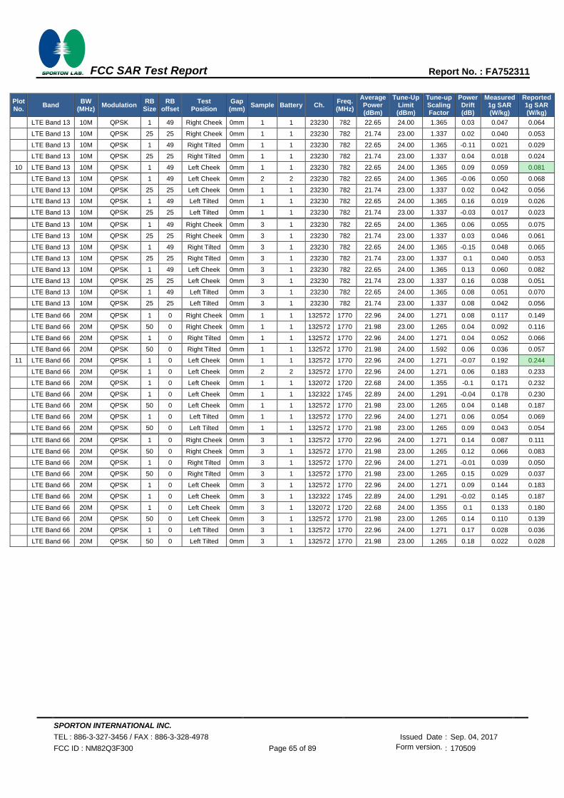
SPORTON INTERNATIONAL INC.
TEL : 886-3-327-3456 / FAX : 886-3-328-4978 Issued Date : Sep. 04, 2017
FCC ID : NM82Q3F300 Page 65 of 89 Form version. : 170509
FCC SAR Test Report Report No. : FA752311
Plot No.
Band BW
(MHz) Modulation
RB Size
RB offset
Test Position
Gap (mm)
Sample Battery Ch. Freq. (MHz)
Average Power (dBm)
Tune-Up Limit (dBm)
Tune-up Scaling Factor
Power Drift (dB)
Measured 1g SAR (W/kg)
Reported 1g SAR (W/kg)
LTE Band 13 10M QPSK 1 49 Right Cheek 0mm 1 1 23230 782 22.65 24.00 1.365 0.03 0.047 0.064
LTE Band 13 10M QPSK 25 25 Right Cheek 0mm 1 1 23230 782 21.74 23.00 1.337 0.02 0.040 0.053
LTE Band 13 10M QPSK 1 49 Right Tilted 0mm 1 1 23230 782 22.65 24.00 1.365 -0.11 0.021 0.029
LTE Band 13 10M QPSK 25 25 Right Tilted 0mm 1 1 23230 782 21.74 23.00 1.337 0.04 0.018 0.024
10 LTE Band 13 10M QPSK 1 49 Left Cheek 0mm 1 1 23230 782 22.65 24.00 1.365 0.09 0.059 0.081
LTE Band 13 10M QPSK 1 49 Left Cheek 0mm 2 2 23230 782 22.65 24.00 1.365 -0.06 0.050 0.068
LTE Band 13 10M QPSK 25 25 Left Cheek 0mm 1 1 23230 782 21.74 23.00 1.337 0.02 0.042 0.056
LTE Band 13 10M QPSK 1 49 Left Tilted 0mm 1 1 23230 782 22.65 24.00 1.365 0.16 0.019 0.026
LTE Band 13 10M QPSK 25 25 Left Tilted 0mm 1 1 23230 782 21.74 23.00 1.337 -0.03 0.017 0.023
LTE Band 13 10M QPSK 1 49 Right Cheek 0mm 3 1 23230 782 22.65 24.00 1.365 0.06 0.055 0.075
LTE Band 13 10M QPSK 25 25 Right Cheek 0mm 3 1 23230 782 21.74 23.00 1.337 0.03 0.046 0.061
LTE Band 13 10M QPSK 1 49 Right Tilted 0mm 3 1 23230 782 22.65 24.00 1.365 -0.15 0.048 0.065
LTE Band 13 10M QPSK 25 25 Right Tilted 0mm 3 1 23230 782 21.74 23.00 1.337 0.1 0.040 0.053
LTE Band 13 10M QPSK 1 49 Left Cheek 0mm 3 1 23230 782 22.65 24.00 1.365 0.13 0.060 0.082
LTE Band 13 10M QPSK 25 25 Left Cheek 0mm 3 1 23230 782 21.74 23.00 1.337 0.16 0.038 0.051
LTE Band 13 10M QPSK 1 49 Left Tilted 0mm 3 1 23230 782 22.65 24.00 1.365 0.08 0.051 0.070
LTE Band 13 10M QPSK 25 25 Left Tilted 0mm 3 1 23230 782 21.74 23.00 1.337 0.08 0.042 0.056
LTE Band 66 20M QPSK 1 0 Right Cheek 0mm 1 1 132572 1770 22.96 24.00 1.271 0.08 0.117 0.149
LTE Band 66 20M QPSK 50 0 Right Cheek 0mm 1 1 132572 1770 21.98 23.00 1.265 0.04 0.092 0.116
LTE Band 66 20M QPSK 1 0 Right Tilted 0mm 1 1 132572 1770 22.96 24.00 1.271 0.04 0.052 0.066
LTE Band 66 20M QPSK 50 0 Right Tilted 0mm 1 1 132572 1770 21.98 24.00 1.592 0.06 0.036 0.057
11 LTE Band 66 20M QPSK 1 0 Left Cheek 0mm 1 1 132572 1770 22.96 24.00 1.271 -0.07 0.192 0.244
LTE Band 66 20M QPSK 1 0 Left Cheek 0mm 2 2 132572 1770 22.96 24.00 1.271 0.06 0.183 0.233
LTE Band 66 20M QPSK 1 0 Left Cheek 0mm 1 1 132072 1720 22.68 24.00 1.355 -0.1 0.171 0.232
LTE Band 66 20M QPSK 1 0 Left Cheek 0mm 1 1 132322 1745 22.89 24.00 1.291 -0.04 0.178 0.230
LTE Band 66 20M QPSK 50 0 Left Cheek 0mm 1 1 132572 1770 21.98 23.00 1.265 0.04 0.148 0.187
LTE Band 66 20M QPSK 1 0 Left Tilted 0mm 1 1 132572 1770 22.96 24.00 1.271 0.06 0.054 0.069
LTE Band 66 20M QPSK 50 0 Left Tilted 0mm 1 1 132572 1770 21.98 23.00 1.265 0.09 0.043 0.054
LTE Band 66 20M QPSK 1 0 Right Cheek 0mm 3 1 132572 1770 22.96 24.00 1.271 0.14 0.087 0.111
LTE Band 66 20M QPSK 50 0 Right Cheek 0mm 3 1 132572 1770 21.98 23.00 1.265 0.12 0.066 0.083
LTE Band 66 20M QPSK 1 0 Right Tilted 0mm 3 1 132572 1770 22.96 24.00 1.271 -0.01 0.039 0.050
LTE Band 66 20M QPSK 50 0 Right Tilted 0mm 3 1 132572 1770 21.98 23.00 1.265 0.15 0.029 0.037
LTE Band 66 20M QPSK 1 0 Left Cheek 0mm 3 1 132572 1770 22.96 24.00 1.271 0.09 0.144 0.183
LTE Band 66 20M QPSK 1 0 Left Cheek 0mm 3 1 132322 1745 22.89 24.00 1.291 -0.02 0.145 0.187
LTE Band 66 20M QPSK 1 0 Left Cheek 0mm 3 1 132072 1720 22.68 24.00 1.355 0.1 0.133 0.180
LTE Band 66 20M QPSK 50 0 Left Cheek 0mm 3 1 132572 1770 21.98 23.00 1.265 0.14 0.110 0.139
LTE Band 66 20M QPSK 1 0 Left Tilted 0mm 3 1 132572 1770 22.96 24.00 1.271 0.17 0.028 0.036
LTE Band 66 20M QPSK 50 0 Left Tilted 0mm 3 1 132572 1770 21.98 23.00 1.265 0.18 0.022 0.028

SPORTON INTERNATIONAL INC.
TEL : 886-3-327-3456 / FAX : 886-3-328-4978 Issued Date : Sep. 04, 2017
FCC ID : NM82Q3F300 Page 66 of 89 Form version. : 170509
FCC SAR Test Report Report No. : FA752311
<WLAN SAR>
Plot No.
Band Mode Test
Position Gap (mm)
Sample Battery Ch. Freq. (MHz)
Average Power (dBm)
Tune-Up Limit (dBm)
Tune-up Scaling Factor
Duty Cycle
%
Duty Cycle
Scaling Factor
Power Drift (dB)
Measured 1g SAR (W/kg)
Reported 1g SAR (W/kg)
WLAN2.4GHz 802.11b 1Mbps Right Cheek 0mm 1 1 1 2412 18.10 19.00 1.230 100 1.000 0.07 0.075 0.092
WLAN2.4GHz 802.11b 1Mbps Right Tilted 0mm 1 1 1 2412 18.10 19.00 1.230 100 1.000 0.01 0.083 0.102
WLAN2.4GHz 802.11b 1Mbps Left Cheek 0mm 1 1 1 2412 18.10 19.00 1.230 100 1.000 0.03 0.196 0.241
WLAN2.4GHz 802.11b 1Mbps Left Cheek 0mm 1 1 6 2437 17.03 19.00 1.574 100 1.000 0.1 0.134 0.211
12 WLAN2.4GHz 802.11b 1Mbps Left Cheek 0mm 1 1 11 2462 18.01 19.00 1.256 100 1.000 0.05 0.231 0.290
WLAN2.4GHz 802.11b 1Mbps Left Cheek 0mm 2 2 11 2462 18.01 19.00 1.256 100 1.000 0.18 0.099 0.124
WLAN2.4GHz 802.11b 1Mbps Left Tilted 0mm 1 1 1 2412 18.10 19.00 1.230 100 1.000 0.07 0.117 0.144
WLAN5GHz 802.11ac-VHT80 MCS0 Right Cheek 0mm 1 1 58 5290 16.50 18.50 1.585 85.19 1.174 0 0.001 0.002
WLAN5GHz 802.11ac-VHT80 MCS0 Right Tilted 0mm 1 1 58 5290 16.50 18.50 1.585 85.19 1.174 0 0.001 0.002
13 WLAN5GHz 802.11ac-VHT80 MCS0 Left Cheek 0mm 1 1 58 5290 16.50 18.50 1.585 85.19 1.174 0.08 0.010 0.018
WLAN5GHz 802.11ac-VHT80 MCS0 Left Tilted 0mm 1 1 58 5290 16.50 18.50 1.585 85.19 1.174 0.05 0.001 0.002
WLAN5GHz 802.11ac-VHT80 MCS0 Right Cheek 0mm 1 1 106 5530 16.61 18.50 1.547 85.19 1.174 -0.1 0.105 0.191
WLAN5GHz 802.11ac-VHT80 MCS0 Right Tilted 0mm 1 1 106 5530 16.61 18.50 1.547 85.19 1.174 -0.02 0.095 0.172
14 WLAN5GHz 802.11ac-VHT80 MCS0 Left Cheek 0mm 1 1 106 5530 16.61 18.50 1.547 85.19 1.174 0.02 0.107 0.194
WLAN5GHz 802.11ac-VHT80 MCS0 Left Tilted 0mm 1 1 106 5530 16.61 18.50 1.547 85.19 1.174 0.03 0.078 0.142
15 WLAN5GHz 802.11ac-VHT80 MCS0 Right Cheek 0mm 1 1 155 5775 16.52 18.50 1.578 85.19 1.174 -0.08 0.176 0.326
WLAN5GHz 802.11ac-VHT80 MCS0 Right Cheek 0mm 2 2 155 5775 16.52 18.50 1.578 85.19 1.174 -0.04 0.125 0.232
WLAN5GHz 802.11ac-VHT80 MCS0 Right Tilted 0mm 1 1 155 5775 16.52 18.50 1.578 85.19 1.174 -0.14 0.123 0.228
WLAN5GHz 802.11ac-VHT80 MCS0 Left Cheek 0mm 1 1 155 5775 16.52 18.50 1.578 85.19 1.174 0.01 0.115 0.213
WLAN5GHz 802.11ac-VHT80 MCS0 Left Tilted 0mm 1 1 155 5775 16.52 18.50 1.578 85.19 1.174 0.03 0.096 0.178
<Bluetooth SAR>
Plot No.
Band Mode Test
Position Gap (mm)
Sample Battery Ch. Freq. (MHz)
Average Power (dBm)
Tune-Up Limit (dBm)
Tune-up Scaling Factor
Duty Cycle
%
Duty Cycle
Scaling Factor
Power Drift (dB)
Measured 1g SAR (W/kg)
Reported 1g SAR (W/kg)
Bluetooth 1Mbps Right Cheek 0mm 1 1 0 2402 7.34 7.50 1.038 77.13 1.080 0.01 0.001 0.001
Bluetooth 1Mbps Right Tilted 0mm 1 1 0 2402 7.34 7.50 1.038 77.13 1.080 0.06 0.001 0.001
Bluetooth 1Mbps Left Cheek 0mm 1 1 0 2402 7.34 7.50 1.038 77.13 1.080 -0.08 0.003 0.004
Bluetooth 1Mbps Left Cheek 0mm 1 1 39 2441 5.64 7.50 1.535 77.13 1.080 -0.09 0.002 0.004
16 Bluetooth 1Mbps Left Cheek 0mm 1 1 78 2480 6.81 7.50 1.172 77.13 1.080 -0.08 0.007 0.008
Bluetooth 1Mbps Left Cheek 0mm 2 2 78 2480 6.81 7.50 1.172 77.13 1.080 -0.18 0.003 0.003
Bluetooth 1Mbps Left Tilted 0mm 1 1 0 2402 7.34 7.50 1.038 77.13 1.080 0.06 0.001 0.001
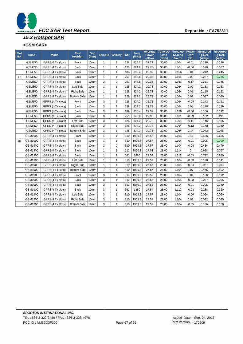
SPORTON INTERNATIONAL INC.
TEL : 886-3-327-3456 / FAX : 886-3-328-4978 Issued Date : Sep. 04, 2017
FCC ID : NM82Q3F300 Page 67 of 89 Form version. : 170509
FCC SAR Test Report Report No. : FA752311
15.2 Hotspot SAR
<GSM SAR>
Plot No.
Band Mode Test
Position Gap (mm)
Sample Battery Ch. Freq. (MHz)
Average Power (dBm)
Tune-Up Limit (dBm)
Tune-up Scaling Factor
Power Drift (dB)
Measured 1g SAR (W/kg)
Reported 1g SAR (W/kg)
GSM850 GPRS(4 Tx slots) Front 10mm 1 1 128 824.2 29.73 30.00 1.064 -0.01 0.128 0.136
GSM850 GPRS(4 Tx slots) Back 10mm 1 1 128 824.2 29.73 30.00 1.064 -0.06 0.176 0.187
GSM850 GPRS(4 Tx slots) Back 10mm 1 1 189 836.4 29.37 30.00 1.156 0.01 0.212 0.245
17 GSM850 GPRS(4 Tx slots) Back 10mm 1 1 251 848.8 29.35 30.00 1.161 0.03 0.237 0.275
GSM850 GPRS(4 Tx slots) Back 10mm 2 2 251 848.8 29.35 30.00 1.161 -0.17 0.211 0.245
GSM850 GPRS(4 Tx slots) Left Side 10mm 1 1 128 824.2 29.73 30.00 1.064 0.07 0.153 0.163
GSM850 GPRS(4 Tx slots) Right Side 10mm 1 1 128 824.2 29.73 30.00 1.064 0.01 0.115 0.122
GSM850 GPRS(4 Tx slots) Bottom Side 10mm 1 1 128 824.2 29.73 30.00 1.064 0.02 0.037 0.039
GSM850 GPRS (4 Tx slots) Front 10mm 3 1 128 824.2 29.73 30.00 1.064 -0.08 0.142 0.151
GSM850 GPRS (4 Tx slots) Back 10mm 3 1 128 824.2 29.73 30.00 1.064 0.08 0.178 0.189
GSM850 GPRS (4 Tx slots) Back 10mm 3 1 189 836.4 29.37 30.00 1.156 -0.06 0.166 0.192
GSM850 GPRS (4 Tx slots) Back 10mm 3 1 251 848.8 29.35 30.00 1.161 -0.09 0.182 0.211
GSM850 GPRS (4 Tx slots) Left Side 10mm 3 1 128 824.2 29.73 30.00 1.064 -0.11 0.146 0.155
GSM850 GPRS (4 Tx slots) Right Side 10mm 3 1 128 824.2 29.73 30.00 1.064 -0.13 0.140 0.149
GSM850 GPRS (4 Tx slots) Bottom Side 10mm 3 1 128 824.2 29.73 30.00 1.064 0.14 0.042 0.045
GSM1900 GPRS(4 Tx slots) Front 10mm 1 1 810 1909.8 27.57 28.00 1.104 0.16 0.566 0.625
18 GSM1900 GPRS(4 Tx slots) Back 10mm 1 1 810 1909.8 27.57 28.00 1.104 -0.01 0.905 0.999
GSM1900 GPRS(4 Tx slots) Back 10mm 2 2 810 1909.8 27.57 28.00 1.104 -0.08 0.434 0.479
GSM1900 GPRS(4 Tx slots) Back 10mm 1 1 512 1850.2 27.53 28.00 1.114 0 0.688 0.767
GSM1900 GPRS(4 Tx slots) Back 10mm 1 1 661 1880 27.54 28.00 1.112 -0.05 0.792 0.880
GSM1900 GPRS(4 Tx slots) Left Side 10mm 1 1 810 1909.8 27.57 28.00 1.104 -0.03 0.128 0.141
GSM1900 GPRS(4 Tx slots) Right Side 10mm 1 1 810 1909.8 27.57 28.00 1.104 -0.04 0.067 0.074
GSM1900 GPRS(4 Tx slots) Bottom Side 10mm 1 1 810 1909.8 27.57 28.00 1.104 0.07 0.455 0.502
GSM1900 GPRS(4 Tx slots) Front 10mm 3 1 810 1909.8 27.57 28.00 1.104 0.04 0.156 0.172
GSM1900 GPRS(4 Tx slots) Back 10mm 3 1 810 1909.8 27.57 28.00 1.104 -0.03 0.267 0.295
GSM1900 GPRS(4 Tx slots) Back 10mm 3 1 512 1850.2 27.53 28.00 1.114 -0.01 0.305 0.340
GSM1900 GPRS(4 Tx slots) Back 10mm 3 1 661 1880 27.54 28.00 1.112 -0.03 0.288 0.320
GSM1900 GPRS(4 Tx slots) Left Side 10mm 3 1 810 1909.8 27.57 28.00 1.104 -0.06 0.054 0.060
GSM1900 GPRS(4 Tx slots) Right Side 10mm 3 1 810 1909.8 27.57 28.00 1.104 0.03 0.032 0.035
GSM1900 GPRS(4 Tx slots) Bottom Side 10mm 3 1 810 1909.8 27.57 28.00 1.104 -0.05 0.136 0.150

SPORTON INTERNATIONAL INC.
TEL : 886-3-327-3456 / FAX : 886-3-328-4978 Issued Date : Sep. 04, 2017
FCC ID : NM82Q3F300 Page 68 of 89 Form version. : 170509
FCC SAR Test Report Report No. : FA752311
<WCDMA SAR>
Plot No.
Band Mode Test
Position Gap (mm)
Sample Battery Ch. Freq. (MHz)
Average Power (dBm)
Tune-Up Limit (dBm)
Tune-up Scaling Factor
Power Drift (dB)
Measured 1g SAR (W/kg)
Reported 1g SAR (W/kg)
WCDMA II RMC 12.2Kbps Front 10mm 1 1 9538 1907.6 23.69 24.50 1.205 0 0.299 0.360
19 WCDMA II RMC 12.2Kbps Back 10mm 1 1 9538 1907.6 23.69 24.50 1.205 -0.12 0.577 0.695
WCDMA II RMC 12.2Kbps Back 10mm 2 2 9538 1907.6 23.69 24.50 1.205 -0.03 0.574 0.692
WCDMA II RMC 12.2Kbps Back 10mm 1 1 9262 1852.4 23.24 24.50 1.337 -0.01 0.447 0.597
WCDMA II RMC 12.2Kbps Back 10mm 1 1 9400 1880 23.62 24.50 1.225 -0.01 0.434 0.531
WCDMA II RMC 12.2Kbps Left Side 10mm 1 1 9538 1907.6 23.69 24.50 1.205 -0.02 0.138 0.166
WCDMA II RMC 12.2Kbps Right Side 10mm 1 1 9538 1907.6 23.69 24.50 1.205 -0.03 0.071 0.086
WCDMA II RMC 12.2Kbps Bottom Side 10mm 1 1 9538 1907.6 23.69 24.50 1.205 0.13 0.238 0.287
WCDMA II RMC 12.2Kbps Front 10mm 3 1 9538 1907.6 23.69 24.50 1.205 -0.07 0.182 0.219
WCDMA II RMC 12.2Kbps Back 10mm 3 1 9538 1907.6 23.69 24.50 1.205 -0.12 0.308 0.371
WCDMA II RMC 12.2Kbps Back 10mm 3 1 9262 1852.4 23.24 24.50 1.337 -0.01 0.356 0.476
WCDMA II RMC 12.2Kbps Back 10mm 3 1 9400 1880 23.62 24.50 1.225 0.01 0.346 0.424
WCDMA II RMC 12.2Kbps Left Side 10mm 3 1 9538 1907.6 23.69 24.50 1.205 0.13 0.035 0.042
WCDMA II RMC 12.2Kbps Right Side 10mm 3 1 9538 1907.6 23.69 24.50 1.205 0.12 0.009 0.011
WCDMA II RMC 12.2Kbps Bottom Side 10mm 3 1 9538 1907.6 23.69 24.50 1.205 0.01 0.175 0.211
WCDMA IV RMC 12.2Kbps Front 10mm 1 1 1413 1732.6 23.82 24.50 1.169 -0.01 0.327 0.382
WCDMA IV RMC 12.2Kbps Back 10mm 1 1 1413 1732.6 23.82 24.50 1.169 0.01 0.404 0.472
WCDMA IV RMC 12.2Kbps Back 10mm 1 1 1312 1712.4 23.60 24.50 1.230 -0.02 0.395 0.486
20 WCDMA IV RMC 12.2Kbps Back 10mm 1 1 1513 1752.6 23.72 24.50 1.197 0 0.486 0.582
WCDMA IV RMC 12.2Kbps Back 10mm 2 2 1513 1752.6 23.72 24.50 1.197 -0.15 0.427 0.511
WCDMA IV RMC 12.2Kbps Left Side 10mm 1 1 1413 1732.6 23.82 24.50 1.169 0.01 0.175 0.205
WCDMA IV RMC 12.2Kbps Right Side 10mm 1 1 1413 1732.6 23.82 24.50 1.169 0.04 0.069 0.081
WCDMA IV RMC 12.2Kbps Bottom Side 10mm 1 1 1413 1732.6 23.82 24.50 1.169 0.07 0.205 0.240
WCDMA IV RMC 12.2Kbps Front 10mm 3 1 1413 1732.6 23.82 24.50 1.169 -0.1 0.238 0.278
WCDMA IV RMC 12.2Kbps Back 10mm 3 1 1413 1732.6 23.82 24.50 1.169 0.01 0.363 0.425
WCDMA IV RMC 12.2Kbps Back 10mm 3 1 1312 1712.4 23.60 24.50 1.230 -0.18 0.321 0.395
WCDMA IV RMC 12.2Kbps Back 10mm 3 1 1513 1752.6 23.72 24.50 1.197 -0.1 0.328 0.393
WCDMA IV RMC 12.2Kbps Left Side 10mm 3 1 1413 1732.6 23.82 24.50 1.169 -0.01 0.093 0.109
WCDMA IV RMC 12.2Kbps Right Side 10mm 3 1 1413 1732.6 23.82 24.50 1.169 -0.06 0.045 0.053
WCDMA IV RMC 12.2Kbps Bottom Side 10mm 3 1 1413 1732.6 23.82 24.50 1.169 -0.03 0.223 0.261
WCDMA V RMC 12.2Kbps Front 10mm 1 1 4182 836.4 22.98 24.50 1.419 0.05 0.076 0.108
WCDMA V RMC 12.2Kbps Back 10mm 1 1 4182 836.4 22.98 24.50 1.419 0.02 0.111 0.158
WCDMA V RMC 12.2Kbps Back 10mm 1 1 4132 826.4 22.97 24.50 1.422 -0.06 0.098 0.139
21 WCDMA V RMC 12.2Kbps Back 10mm 1 1 4233 846.6 22.66 24.50 1.528 -0.01 0.121 0.185
WCDMA V RMC 12.2Kbps Back 10mm 2 2 4233 846.6 22.66 24.50 1.528 -0.03 0.118 0.180
WCDMA V RMC 12.2Kbps Left Side 10mm 1 1 4182 836.4 22.98 24.50 1.419 0.01 0.086 0.122
WCDMA V RMC 12.2Kbps Right Side 10mm 1 1 4182 836.4 22.98 24.50 1.419 -0.01 0.075 0.106
WCDMA V RMC 12.2Kbps Bottom Side 10mm 1 1 4182 836.4 22.98 24.50 1.419 0 0.026 0.037
WCDMA V RMC 12.2Kbps Front 10mm 3 1 4182 836.4 22.98 24.50 1.419 0.01 0.090 0.128
WCDMA V RMC 12.2Kbps Back 10mm 3 1 4182 836.4 22.98 24.50 1.419 -0.03 0.118 0.167
WCDMA V RMC 12.2Kbps Back 10mm 3 1 4132 826.4 22.97 24.50 1.422 0.04 0.107 0.152
WCDMA V RMC 12.2Kbps Back 10mm 3 1 4233 846.6 22.66 24.50 1.528 -0.04 0.116 0.177
WCDMA V RMC 12.2Kbps Left Side 10mm 3 1 4182 836.4 22.98 24.50 1.419 -0.02 0.087 0.123
WCDMA V RMC 12.2Kbps Right Side 10mm 3 1 4182 836.4 22.98 24.50 1.419 -0.04 0.087 0.123
WCDMA V RMC 12.2Kbps Bottom Side 10mm 3 1 4182 836.4 22.98 24.50 1.419 0.04 0.028 0.040

SPORTON INTERNATIONAL INC.
TEL : 886-3-327-3456 / FAX : 886-3-328-4978 Issued Date : Sep. 04, 2017
FCC ID : NM82Q3F300 Page 69 of 89 Form version. : 170509
FCC SAR Test Report Report No. : FA752311
<LTE SAR>
Plot No.
Band BW
(MHz) Modulation
RB Size
RB offset
Test Position
Gap (mm)
Sample Battery Ch. Freq. (MHz)
Average Power (dBm)
Tune-Up Limit (dBm)
Tune-up Scaling Factor
Power Drift (dB)
Measured 1g SAR (W/kg)
Reported 1g SAR (W/kg)
LTE Band 2 20M QPSK 1 0 Front 10mm 1 1 19100 1900 22.80 24.00 1.318 0.02 0.251 0.331
LTE Band 2 20M QPSK 50 0 Front 10mm 1 1 19100 1900 21.91 23.00 1.285 -0.02 0.202 0.260
22 LTE Band 2 20M QPSK 1 0 Back 10mm 1 1 19100 1900 22.80 24.00 1.318 0.14 0.418 0.551
LTE Band 2 20M QPSK 1 0 Back 10mm 2 2 19100 1900 22.80 24.00 1.318 -0.17 0.382 0.504
LTE Band 2 20M QPSK 1 0 Back 10mm 1 1 18700 1860 22.65 24.00 1.365 0 0.362 0.494
LTE Band 2 20M QPSK 1 0 Back 10mm 1 1 18900 1880 22.74 24.00 1.337 0.06 0.349 0.466
LTE Band 2 20M QPSK 50 0 Back 10mm 1 1 19100 1900 21.91 23.00 1.285 0.09 0.295 0.379
LTE Band 2 20M QPSK 1 0 Left Side 10mm 1 1 19100 1900 22.80 24.00 1.318 0.04 0.112 0.148
LTE Band 2 20M QPSK 50 0 Left Side 10mm 1 1 19100 1900 21.91 23.00 1.285 0.03 0.087 0.112
LTE Band 2 20M QPSK 1 0 Right Side 10mm 1 1 19100 1900 22.80 24.00 1.318 -0.03 0.050 0.066
LTE Band 2 20M QPSK 50 0 Right Side 10mm 1 1 19100 1900 21.91 23.00 1.285 -0.02 0.038 0.049
LTE Band 2 20M QPSK 1 0 Bottom Side 10mm 1 1 19100 1900 22.80 24.00 1.318 0.08 0.181 0.239
LTE Band 2 20M QPSK 50 0 Bottom Side 10mm 1 1 19100 1900 21.91 23.00 1.285 0.16 0.165 0.212
LTE Band 2 20M QPSK 1 0 Front 10mm 3 1 19100 1900 22.80 24.00 1.318 -0.12 0.154 0.203
LTE Band 2 20M QPSK 50 0 Front 10mm 3 1 19100 1900 21.91 23.00 1.285 -0.03 0.115 0.148
LTE Band 2 20M QPSK 1 0 Back 10mm 3 1 19100 1900 22.80 24.00 1.318 0.02 0.266 0.351
LTE Band 2 20M QPSK 1 0 Back 10mm 3 1 18700 1860 22.65 24.00 1.365 0 0.298 0.407
LTE Band 2 20M QPSK 1 0 Back 10mm 3 1 18900 1880 22.74 24.00 1.337 0.02 0.284 0.380
LTE Band 2 20M QPSK 50 0 Back 10mm 3 1 19100 1900 21.91 23.00 1.285 0 0.208 0.267
LTE Band 2 20M QPSK 1 0 Left Side 10mm 3 1 19100 1900 22.80 24.00 1.318 0.08 0.031 0.041
LTE Band 2 20M QPSK 50 0 Left Side 10mm 3 1 19100 1900 21.91 23.00 1.285 0.11 0.023 0.030
LTE Band 2 20M QPSK 1 0 Right Side 10mm 3 1 19100 1900 22.80 24.00 1.318 0.18 0.008 0.010
LTE Band 2 20M QPSK 50 0 Right Side 10mm 3 1 19100 1900 21.91 23.00 1.285 0.13 0.005 0.006
LTE Band 2 20M QPSK 1 0 Bottom Side 10mm 3 1 19100 1900 22.80 24.00 1.318 0.07 0.173 0.228
LTE Band 2 20M QPSK 50 0 Bottom Side 10mm 3 1 19100 1900 21.91 23.00 1.285 -0.02 0.135 0.174
LTE Band 5 10M QPSK 1 0 Front 10mm 1 1 20525 836.5 22.63 24.00 1.371 0.02 0.063 0.086
LTE Band 5 10M QPSK 25 0 Front 10mm 1 1 20525 836.5 21.63 23.00 1.371 0.05 0.052 0.071
23 LTE Band 5 10M QPSK 1 0 Back 10mm 1 1 20525 836.5 22.63 24.00 1.371 -0.03 0.096 0.132
LTE Band 5 10M QPSK 1 0 Back 10mm 2 2 20525 836.5 22.63 24.00 1.371 -0.06 0.085 0.117
LTE Band 5 10M QPSK 25 0 Back 10mm 1 1 20525 836.5 21.63 23.00 1.371 -0.02 0.079 0.108
LTE Band 5 10M QPSK 1 0 Left Side 10mm 1 1 20525 836.5 22.63 24.00 1.371 -0.03 0.080 0.110
LTE Band 5 10M QPSK 25 0 Left Side 10mm 1 1 20525 836.5 21.63 23.00 1.371 0.06 0.064 0.088
LTE Band 5 10M QPSK 1 0 Right Side 10mm 1 1 20525 836.5 22.63 24.00 1.371 -0.01 0.065 0.089
LTE Band 5 10M QPSK 25 0 Right Side 10mm 1 1 20525 836.5 21.63 23.00 1.371 -0.03 0.053 0.073
LTE Band 5 10M QPSK 1 0 Bottom Side 10mm 1 1 20525 836.5 22.63 24.00 1.371 0.09 0.022 0.030
LTE Band 5 10M QPSK 25 0 Bottom Side 10mm 1 1 20525 836.5 21.63 23.00 1.371 -0.09 0.019 0.026
LTE Band 5 10M QPSK 1 0 Front 10mm 3 1 20525 836.5 22.63 24.00 1.371 0 0.073 0.100
LTE Band 5 10M QPSK 25 0 Front 10mm 3 1 20525 836.5 21.63 23.00 1.371 -0.08 0.061 0.084
LTE Band 5 10M QPSK 1 0 Back 10mm 3 1 20525 836.5 22.63 24.00 1.371 -0.05 0.088 0.121
LTE Band 5 10M QPSK 25 0 Back 10mm 3 1 20525 836.5 21.63 23.00 1.371 0.07 0.079 0.108
LTE Band 5 10M QPSK 1 0 Left Side 10mm 3 1 20525 836.5 22.63 24.00 1.371 -0.07 0.071 0.097
LTE Band 5 10M QPSK 25 0 Left Side 10mm 3 1 20525 836.5 21.63 23.00 1.371 0.03 0.058 0.080
LTE Band 5 10M QPSK 1 0 Right Side 10mm 3 1 20525 836.5 22.63 24.00 1.371 0.04 0.071 0.097
LTE Band 5 10M QPSK 25 0 Right Side 10mm 3 1 20525 836.5 21.63 23.00 1.371 -0.02 0.058 0.080
LTE Band 5 10M QPSK 1 0 Bottom Side 10mm 3 1 20525 836.5 22.63 24.00 1.371 0.05 0.023 0.032
LTE Band 5 10M QPSK 25 0 Bottom Side 10mm 3 1 20525 836.5 21.63 23.00 1.371 0.14 0.018 0.025

SPORTON INTERNATIONAL INC.
TEL : 886-3-327-3456 / FAX : 886-3-328-4978 Issued Date : Sep. 04, 2017
FCC ID : NM82Q3F300 Page 70 of 89 Form version. : 170509
FCC SAR Test Report Report No. : FA752311
Plot No.
Band BW
(MHz) Modulation
RB Size
RB offset
Test Position
Gap (mm)
Sample Battery Ch. Freq. (MHz)
Average Power (dBm)
Tune-Up Limit (dBm)
Tune-up Scaling Factor
Power Drift (dB)
Measured 1g SAR (W/kg)
Reported 1g SAR (W/kg)
LTE Band 7 20M QPSK 1 0 Front 10mm 1 1 20850 2510 22.48 24.00 1.419 0.01 0.216 0.307
LTE Band 7 20M QPSK 50 0 Front 10mm 1 1 20850 2510 21.50 23.00 1.413 0.08 0.179 0.253
LTE Band 7 20M QPSK 1 0 Back 10mm 1 1 20850 2510 22.48 24.00 1.419 0.12 0.393 0.558
LTE Band 7 20M QPSK 1 0 Back 10mm 1 1 21100 2535 22.28 24.00 1.486 0 0.433 0.643
24 LTE Band 7 20M QPSK 1 0 Back 10mm 1 1 21350 2560 22.25 24.00 1.496 -0.07 0.459 0.687
LTE Band 7 20M QPSK 1 0 Back 10mm 2 2 21350 2560 22.25 24.00 1.496 -0.11 0.352 0.527
LTE Band 7 20M QPSK 50 0 Back 10mm 1 1 20850 2510 21.50 23.00 1.413 -0.12 0.318 0.449
LTE Band 7 20M QPSK 1 0 Left Side 10mm 1 1 20850 2510 22.48 24.00 1.419 -0.15 0.018 0.026
LTE Band 7 20M QPSK 50 0 Left Side 10mm 1 1 20850 2510 21.50 23.00 1.413 0 0.015 0.021
LTE Band 7 20M QPSK 1 0 Right Side 10mm 1 1 20850 2510 22.48 24.00 1.419 0.04 0.212 0.301
LTE Band 7 20M QPSK 50 0 Right Side 10mm 1 1 20850 2510 21.50 23.00 1.413 -0.03 0.174 0.246
LTE Band 7 20M QPSK 1 0 Bottom Side 10mm 1 1 20850 2510 22.48 24.00 1.419 -0.06 0.066 0.094
LTE Band 7 20M QPSK 50 0 Bottom Side 10mm 1 1 20850 2510 21.50 23.00 1.413 0.03 0.053 0.075
LTE Band 7 20M QPSK 1 0 Front 10mm 3 1 20850 2510 22.48 24.00 1.419 -0.01 0.142 0.202
LTE Band 7 20M QPSK 50 0 Front 10mm 3 1 20850 2510 21.50 23.00 1.413 -0.07 0.120 0.170
LTE Band 7 20M QPSK 1 0 Back 10mm 3 1 20850 2510 22.48 24.00 1.419 0.01 0.269 0.382
LTE Band 7 20M QPSK 1 0 Back 10mm 3 1 21100 2535 22.28 24.00 1.486 0 0.212 0.315
LTE Band 7 20M QPSK 1 0 Back 10mm 3 1 21350 2560 22.25 24.00 1.496 -0.04 0.180 0.269
LTE Band 7 20M QPSK 50 0 Back 10mm 3 1 20850 2510 21.50 23.00 1.413 -0.02 0.198 0.280
LTE Band 7 20M QPSK 1 0 Left Side 10mm 3 1 20850 2510 22.48 24.00 1.419 0.13 0.008 0.011
LTE Band 7 20M QPSK 50 0 Left Side 10mm 3 1 20850 2510 21.50 23.00 1.413 -0.13 0.005 0.008
LTE Band 7 20M QPSK 1 0 Right Side 10mm 3 1 20850 2510 22.48 24.00 1.419 0.03 0.182 0.258
LTE Band 7 20M QPSK 50 0 Right Side 10mm 3 1 20850 2510 21.50 23.00 1.413 0.04 0.142 0.201
LTE Band 7 20M QPSK 1 0 Bottom Side 10mm 3 1 20850 2510 22.48 24.00 1.419 0.03 0.050 0.071
LTE Band 7 20M QPSK 50 0 Bottom Side 10mm 3 1 20850 2510 21.50 23.00 1.413 0.07 0.037 0.052
LTE Band 12 10M QPSK 1 49 Front 10mm 1 1 23095 707.5 22.59 24.00 1.384 0.01 0.080 0.111
LTE Band 12 10M QPSK 25 12 Front 10mm 1 1 23095 707.5 21.51 23.00 1.409 0.03 0.062 0.087
25 LTE Band 12 10M QPSK 1 49 Back 10mm 1 1 23095 707.5 22.59 24.00 1.384 -0.03 0.129 0.178
LTE Band 12 10M QPSK 1 49 Back 10mm 2 2 23095 707.5 22.59 24.00 1.384 -0.09 0.085 0.118
LTE Band 12 10M QPSK 25 12 Back 10mm 1 1 23095 707.5 21.51 23.00 1.409 -0.05 0.098 0.138
LTE Band 12 10M QPSK 1 49 Left Side 10mm 1 1 23095 707.5 22.59 24.00 1.384 0.02 0.078 0.108
LTE Band 12 10M QPSK 25 12 Left Side 10mm 1 1 23095 707.5 21.51 23.00 1.409 0 0.058 0.082
LTE Band 12 10M QPSK 1 49 Right Side 10mm 1 1 23095 707.5 22.59 24.00 1.384 0 0.039 0.054
LTE Band 12 10M QPSK 25 12 Right Side 10mm 1 1 23095 707.5 21.51 23.00 1.409 0.03 0.029 0.041
LTE Band 12 10M QPSK 1 49 Bottom Side 10mm 1 1 23095 707.5 22.59 24.00 1.384 0.11 0.019 0.026
LTE Band 12 10M QPSK 25 12 Bottom Side 10mm 1 1 23095 707.5 21.51 23.00 1.409 -0.01 0.015 0.021
LTE Band 12 10M QPSK 1 49 Front 10mm 3 1 23095 707.5 22.59 24.00 1.384 -0.13 0.042 0.058
LTE Band 12 10M QPSK 25 12 Front 10mm 3 1 23095 707.5 21.51 23.00 1.409 0.02 0.029 0.041
LTE Band 12 10M QPSK 1 49 Back 10mm 3 1 23095 707.5 22.59 24.00 1.384 0.02 0.062 0.086
LTE Band 12 10M QPSK 25 12 Back 10mm 3 1 23095 707.5 21.51 23.00 1.409 -0.04 0.046 0.065
LTE Band 12 10M QPSK 1 49 Left Side 10mm 3 1 23095 707.5 22.59 24.00 1.384 0.05 0.041 0.057
LTE Band 12 10M QPSK 25 12 Left Side 10mm 3 1 23095 707.5 21.51 23.00 1.409 0.03 0.033 0.047
LTE Band 12 10M QPSK 1 49 Right Side 10mm 3 1 23095 707.5 22.59 24.00 1.384 -0.01 0.020 0.028
LTE Band 12 10M QPSK 25 12 Right Side 10mm 3 1 23095 707.5 21.51 23.00 1.409 0.09 0.015 0.021
LTE Band 12 10M QPSK 1 49 Bottom Side 10mm 3 1 23095 707.5 22.59 24.00 1.384 0.17 0.009 0.013
LTE Band 12 10M QPSK 25 12 Bottom Side 10mm 3 1 23095 707.5 21.51 23.00 1.409 0.1 0.007 0.009

SPORTON INTERNATIONAL INC.
TEL : 886-3-327-3456 / FAX : 886-3-328-4978 Issued Date : Sep. 04, 2017
FCC ID : NM82Q3F300 Page 71 of 89 Form version. : 170509
FCC SAR Test Report Report No. : FA752311
Plot No.
Band BW
(MHz) Modulation
RB Size
RB offset
Test Position
Gap (mm)
Sample Battery Ch. Freq. (MHz)
Average Power (dBm)
Tune-Up Limit (dBm)
Tune-up Scaling Factor
Power Drift (dB)
Measured 1g SAR (W/kg)
Reported 1g SAR (W/kg)
LTE Band 13 10M QPSK 1 49 Front 10mm 1 1 23230 782 22.65 24.00 1.365 0 0.072 0.098
LTE Band 13 10M QPSK 25 25 Front 10mm 1 1 23230 782 21.74 23.00 1.337 0 0.060 0.080
26 LTE Band 13 10M QPSK 1 49 Back 10mm 1 1 23230 782 22.65 24.00 1.365 0 0.112 0.153
LTE Band 13 10M QPSK 1 49 Back 10mm 2 2 23230 782 22.65 24.00 1.365 -0.06 0.100 0.136
LTE Band 13 10M QPSK 25 25 Back 10mm 1 1 23230 782 21.74 23.00 1.337 0.01 0.084 0.112
LTE Band 13 10M QPSK 1 49 Left Side 10mm 1 1 23230 782 22.65 24.00 1.365 0 0.097 0.132
LTE Band 13 10M QPSK 25 25 Left Side 10mm 1 1 23230 782 21.74 23.00 1.337 -0.01 0.082 0.110
LTE Band 13 10M QPSK 1 49 Right Side 10mm 1 1 23230 782 22.65 24.00 1.365 0.02 0.068 0.093
LTE Band 13 10M QPSK 25 25 Right Side 10mm 1 1 23230 782 21.74 23.00 1.337 0 0.057 0.076
LTE Band 13 10M QPSK 1 49 Bottom Side 10mm 1 1 23230 782 22.65 24.00 1.365 0.01 0.019 0.026
LTE Band 13 10M QPSK 25 25 Bottom Side 10mm 1 1 23230 782 21.74 23.00 1.337 0.01 0.016 0.021
LTE Band 13 10M QPSK 1 49 Front 10mm 3 1 23230 782 22.65 24.00 1.365 -0.03 0.096 0.131
LTE Band 13 10M QPSK 25 25 Front 10mm 3 1 23230 782 21.74 23.00 1.337 0.1 0.079 0.106
LTE Band 13 10M QPSK 1 49 Back 10mm 3 1 23230 782 22.65 24.00 1.365 0.01 0.107 0.146
LTE Band 13 10M QPSK 25 25 Back 10mm 3 1 23230 782 21.74 23.00 1.337 0.03 0.104 0.139
LTE Band 13 10M QPSK 1 49 Left Side 10mm 3 1 23230 782 22.65 24.00 1.365 -0.11 0.105 0.143
LTE Band 13 10M QPSK 25 25 Left Side 10mm 3 1 23230 782 21.74 23.00 1.337 -0.05 0.094 0.126
LTE Band 13 10M QPSK 1 49 Right Side 10mm 3 1 23230 782 22.65 24.00 1.365 0 0.092 0.126
LTE Band 13 10M QPSK 25 25 Right Side 10mm 3 1 23230 782 21.74 23.00 1.337 0.03 0.075 0.100
LTE Band 13 10M QPSK 1 49 Bottom Side 10mm 3 1 23230 782 22.65 24.00 1.365 0.04 0.022 0.030
LTE Band 13 10M QPSK 25 25 Bottom Side 10mm 3 1 23230 782 21.74 23.00 1.337 0.08 0.018 0.024
LTE Band 66 20M QPSK 1 0 Front 10mm 1 1 132572 1770 22.96 24.00 1.271 0.01 0.275 0.349
LTE Band 66 20M QPSK 50 0 Front 10mm 1 1 132572 1770 21.98 23.00 1.265 0 0.228 0.288
27 LTE Band 66 20M QPSK 1 0 Back 10mm 1 1 132572 1770 22.96 24.00 1.271 0.04 0.365 0.464
LTE Band 66 20M QPSK 1 0 Back 10mm 2 2 132572 1770 22.96 24.00 1.271 -0.16 0.336 0.427
LTE Band 66 20M QPSK 1 0 Back 10mm 1 1 132072 1720 22.68 24.00 1.355 0.01 0.285 0.386
LTE Band 66 20M QPSK 1 0 Back 10mm 1 1 132322 1745 22.89 24.00 1.291 0.02 0.307 0.396
LTE Band 66 20M QPSK 50 0 Back 10mm 1 1 132572 1770 21.98 23.00 1.265 -0.02 0.268 0.339
LTE Band 66 20M QPSK 1 0 Left Side 10mm 1 1 132572 1770 22.96 24.00 1.271 0 0.126 0.160
LTE Band 66 20M QPSK 50 0 Left Side 10mm 1 1 132572 1770 21.98 23.00 1.265 0.03 0.104 0.132
LTE Band 66 20M QPSK 1 0 Right Side 10mm 1 1 132572 1770 22.96 24.00 1.271 0.03 0.050 0.064
LTE Band 66 20M QPSK 50 0 Right Side 10mm 1 1 132572 1770 21.98 23.00 1.265 0.06 0.041 0.052
LTE Band 66 20M QPSK 1 0 Bottom Side 10mm 1 1 132572 1770 22.96 24.00 1.271 0.06 0.166 0.211
LTE Band 66 20M QPSK 50 0 Bottom Side 10mm 1 1 132572 1770 21.98 23.00 1.265 0.04 0.155 0.196
LTE Band 66 20M QPSK 1 0 Front 10mm 3 1 132572 1770 22.96 24.00 1.271 -0.07 0.182 0.231
LTE Band 66 20M QPSK 50 0 Front 10mm 3 1 132572 1770 21.98 23.00 1.265 0 0.136 0.172
LTE Band 66 20M QPSK 1 0 Back 10mm 3 1 132572 1770 22.96 24.00 1.271 -0.1 0.283 0.360
LTE Band 66 20M QPSK 1 0 Back 10mm 3 1 132072 1720 22.68 24.00 1.355 -0.06 0.280 0.379
LTE Band 66 20M QPSK 1 0 Back 10mm 3 1 132322 1745 22.89 24.00 1.291 0.05 0.278 0.359
LTE Band 66 20M QPSK 50 0 Back 10mm 3 1 132572 1770 21.98 23.00 1.265 0.02 0.242 0.306
LTE Band 66 20M QPSK 1 0 Left Side 10mm 3 1 132572 1770 22.96 24.00 1.271 0.05 0.072 0.091
LTE Band 66 20M QPSK 50 0 Left Side 10mm 3 1 132572 1770 21.98 23.00 1.265 -0.03 0.059 0.075
LTE Band 66 20M QPSK 1 0 Right Side 10mm 3 1 132572 1770 22.96 24.00 1.271 -0.04 0.037 0.047
LTE Band 66 20M QPSK 50 0 Right Side 10mm 3 1 132572 1770 21.98 23.00 1.265 -0.16 0.029 0.037
LTE Band 66 20M QPSK 1 0 Bottom Side 10mm 3 1 132572 1770 22.96 24.00 1.271 0.04 0.161 0.205
LTE Band 66 20M QPSK 50 0 Bottom Side 10mm 3 1 132572 1770 21.98 23.00 1.265 0.04 0.132 0.167

SPORTON INTERNATIONAL INC.
TEL : 886-3-327-3456 / FAX : 886-3-328-4978 Issued Date : Sep. 04, 2017
FCC ID : NM82Q3F300 Page 72 of 89 Form version. : 170509
FCC SAR Test Report Report No. : FA752311
<WLAN SAR>
Plot No.
Band Mode Test
Position Gap (mm)
Sample Battery Ch. Freq. (MHz)
Average Power (dBm)
Tune-Up Limit (dBm)
Tune-up Scaling Factor
Duty Cycle
%
Duty Cycle
Scaling Factor
Power Drift (dB)
Measured 1g SAR (W/kg)
Reported 1g SAR (W/kg)
WLAN2.4GHz 802.11b 1Mbps Front 10mm 1 1 1 2412 18.10 19.00 1.230 100 1.000 0.14 0.015 0.018
WLAN2.4GHz 802.11b 1Mbps Back 10mm 1 1 1 2412 18.10 19.00 1.230 100 1.000 -0.04 0.143 0.176
WLAN2.4GHz 802.11b 1Mbps Back 10mm 1 1 6 2437 17.03 19.00 1.574 100 1.000 -0.1 0.158 0.249
28 WLAN2.4GHz 802.11b 1Mbps Back 10mm 1 1 11 2462 18.01 19.00 1.256 100 1.000 -0.09 0.250 0.314
WLAN2.4GHz 802.11b 1Mbps Back 10mm 2 2 11 2462 18.01 19.00 1.256 100 1.000 -0.19 0.176 0.221
WLAN2.4GHz 802.11b 1Mbps Right Side 10mm 1 1 1 2412 18.10 19.00 1.230 100 1.000 0.11 0.072 0.089
WLAN2.4GHz 802.11b 1Mbps Top Side 10mm 1 1 1 2412 18.10 19.00 1.230 100 1.000 0.08 0.004 0.005
WLAN5GHz 802.11ac-VHT80 MCS0 Front 10mm 1 1 42 5210 16.53 18.50 1.575 85.19 1.174 0 < 0.001 < 0.001
29 WLAN5GHz 802.11ac-VHT80 MCS0 Back 10mm 1 1 42 5210 16.53 18.50 1.575 85.19 1.174 0.04 0.051 0.094
WLAN5GHz 802.11ac-VHT80 MCS0 Back 10mm 1 1 42 5210 16.53 18.50 1.575 85.19 1.174 0.15 0.022 0.041
WLAN5GHz 802.11ac-VHT80 MCS0 Right Side 10mm 1 1 42 5210 16.53 18.50 1.575 85.19 1.174 0 < 0.001 < 0.001
WLAN5GHz 802.11ac-VHT80 MCS0 Top Side 10mm 1 1 42 5210 16.53 18.50 1.575 85.19 1.174 0 < 0.001 < 0.001
WLAN5GHz 802.11ac-VHT80 MCS0 Front 10mm 1 1 155 5775 16.52 18.50 1.578 85.19 1.174 0 < 0.001 < 0.001
WLAN5GHz 802.11ac-VHT80 MCS0 Back 10mm 1 1 155 5775 16.52 18.50 1.578 85.19 1.174 0 < 0.001 < 0.001
WLAN5GHz 802.11ac-VHT80 MCS0 Right Side 10mm 1 1 155 5775 16.52 18.50 1.578 85.19 1.174 0 < 0.001 < 0.001
WLAN5GHz 802.11ac-VHT80 MCS0 Top Side 10mm 1 1 155 5775 16.52 18.50 1.578 85.19 1.174 0 < 0.001 < 0.001
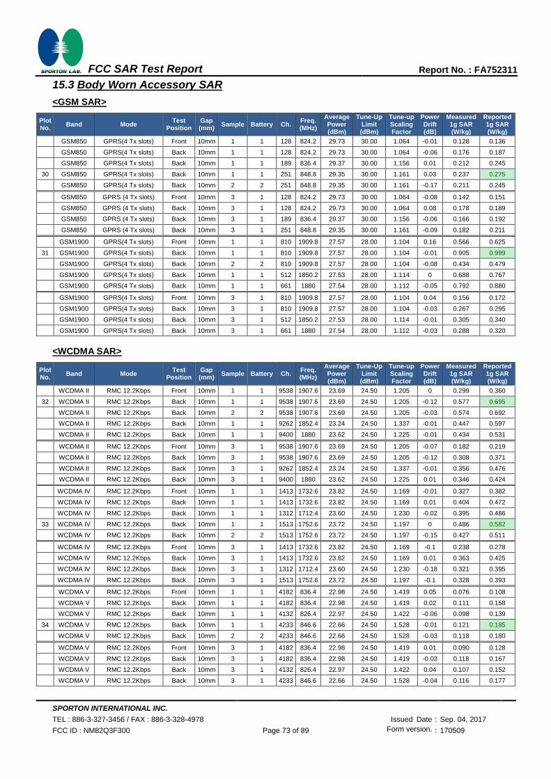
SPORTON INTERNATIONAL INC.
TEL : 886-3-327-3456 / FAX : 886-3-328-4978 Issued Date : Sep. 04, 2017
FCC ID : NM82Q3F300 Page 73 of 89 Form version. : 170509
FCC SAR Test Report Report No. : FA752311
15.3 Body Worn Accessory SAR
<GSM SAR>
Plot No.
Band Mode Test
Position Gap (mm)
Sample Battery Ch. Freq. (MHz)
Average Power (dBm)
Tune-Up Limit (dBm)
Tune-up Scaling Factor
Power Drift (dB)
Measured 1g SAR (W/kg)
Reported 1g SAR (W/kg)
GSM850 GPRS(4 Tx slots) Front 10mm 1 1 128 824.2 29.73 30.00 1.064 -0.01 0.128 0.136
GSM850 GPRS(4 Tx slots) Back 10mm 1 1 128 824.2 29.73 30.00 1.064 -0.06 0.176 0.187
GSM850 GPRS(4 Tx slots) Back 10mm 1 1 189 836.4 29.37 30.00 1.156 0.01 0.212 0.245
30 GSM850 GPRS(4 Tx slots) Back 10mm 1 1 251 848.8 29.35 30.00 1.161 0.03 0.237 0.275
GSM850 GPRS(4 Tx slots) Back 10mm 2 2 251 848.8 29.35 30.00 1.161 -0.17 0.211 0.245
GSM850 GPRS (4 Tx slots) Front 10mm 3 1 128 824.2 29.73 30.00 1.064 -0.08 0.142 0.151
GSM850 GPRS (4 Tx slots) Back 10mm 3 1 128 824.2 29.73 30.00 1.064 0.08 0.178 0.189
GSM850 GPRS (4 Tx slots) Back 10mm 3 1 189 836.4 29.37 30.00 1.156 -0.06 0.166 0.192
GSM850 GPRS (4 Tx slots) Back 10mm 3 1 251 848.8 29.35 30.00 1.161 -0.09 0.182 0.211
GSM1900 GPRS(4 Tx slots) Front 10mm 1 1 810 1909.8 27.57 28.00 1.104 0.16 0.566 0.625
31 GSM1900 GPRS(4 Tx slots) Back 10mm 1 1 810 1909.8 27.57 28.00 1.104 -0.01 0.905 0.999
GSM1900 GPRS(4 Tx slots) Back 10mm 2 2 810 1909.8 27.57 28.00 1.104 -0.08 0.434 0.479
GSM1900 GPRS(4 Tx slots) Back 10mm 1 1 512 1850.2 27.53 28.00 1.114 0 0.688 0.767
GSM1900 GPRS(4 Tx slots) Back 10mm 1 1 661 1880 27.54 28.00 1.112 -0.05 0.792 0.880
GSM1900 GPRS(4 Tx slots) Front 10mm 3 1 810 1909.8 27.57 28.00 1.104 0.04 0.156 0.172
GSM1900 GPRS(4 Tx slots) Back 10mm 3 1 810 1909.8 27.57 28.00 1.104 -0.03 0.267 0.295
GSM1900 GPRS(4 Tx slots) Back 10mm 3 1 512 1850.2 27.53 28.00 1.114 -0.01 0.305 0.340
GSM1900 GPRS(4 Tx slots) Back 10mm 3 1 661 1880 27.54 28.00 1.112 -0.03 0.288 0.320
<WCDMA SAR>
Plot No.
Band Mode Test
Position Gap (mm)
Sample Battery Ch. Freq. (MHz)
Average Power (dBm)
Tune-Up Limit (dBm)
Tune-up Scaling Factor
Power Drift (dB)
Measured 1g SAR (W/kg)
Reported 1g SAR (W/kg)
WCDMA II RMC 12.2Kbps Front 10mm 1 1 9538 1907.6 23.69 24.50 1.205 0 0.299 0.360
32 WCDMA II RMC 12.2Kbps Back 10mm 1 1 9538 1907.6 23.69 24.50 1.205 -0.12 0.577 0.695
WCDMA II RMC 12.2Kbps Back 10mm 2 2 9538 1907.6 23.69 24.50 1.205 -0.03 0.574 0.692
WCDMA II RMC 12.2Kbps Back 10mm 1 1 9262 1852.4 23.24 24.50 1.337 -0.01 0.447 0.597
WCDMA II RMC 12.2Kbps Back 10mm 1 1 9400 1880 23.62 24.50 1.225 -0.01 0.434 0.531
WCDMA II RMC 12.2Kbps Front 10mm 3 1 9538 1907.6 23.69 24.50 1.205 -0.07 0.182 0.219
WCDMA II RMC 12.2Kbps Back 10mm 3 1 9538 1907.6 23.69 24.50 1.205 -0.12 0.308 0.371
WCDMA II RMC 12.2Kbps Back 10mm 3 1 9262 1852.4 23.24 24.50 1.337 -0.01 0.356 0.476
WCDMA II RMC 12.2Kbps Back 10mm 3 1 9400 1880 23.62 24.50 1.225 0.01 0.346 0.424
WCDMA IV RMC 12.2Kbps Front 10mm 1 1 1413 1732.6 23.82 24.50 1.169 -0.01 0.327 0.382
WCDMA IV RMC 12.2Kbps Back 10mm 1 1 1413 1732.6 23.82 24.50 1.169 0.01 0.404 0.472
WCDMA IV RMC 12.2Kbps Back 10mm 1 1 1312 1712.4 23.60 24.50 1.230 -0.02 0.395 0.486
33 WCDMA IV RMC 12.2Kbps Back 10mm 1 1 1513 1752.6 23.72 24.50 1.197 0 0.486 0.582
WCDMA IV RMC 12.2Kbps Back 10mm 2 2 1513 1752.6 23.72 24.50 1.197 -0.15 0.427 0.511
WCDMA IV RMC 12.2Kbps Front 10mm 3 1 1413 1732.6 23.82 24.50 1.169 -0.1 0.238 0.278
WCDMA IV RMC 12.2Kbps Back 10mm 3 1 1413 1732.6 23.82 24.50 1.169 0.01 0.363 0.425
WCDMA IV RMC 12.2Kbps Back 10mm 3 1 1312 1712.4 23.60 24.50 1.230 -0.18 0.321 0.395
WCDMA IV RMC 12.2Kbps Back 10mm 3 1 1513 1752.6 23.72 24.50 1.197 -0.1 0.328 0.393
WCDMA V RMC 12.2Kbps Front 10mm 1 1 4182 836.4 22.98 24.50 1.419 0.05 0.076 0.108
WCDMA V RMC 12.2Kbps Back 10mm 1 1 4182 836.4 22.98 24.50 1.419 0.02 0.111 0.158
WCDMA V RMC 12.2Kbps Back 10mm 1 1 4132 826.4 22.97 24.50 1.422 -0.06 0.098 0.139
34 WCDMA V RMC 12.2Kbps Back 10mm 1 1 4233 846.6 22.66 24.50 1.528 -0.01 0.121 0.185
WCDMA V RMC 12.2Kbps Back 10mm 2 2 4233 846.6 22.66 24.50 1.528 -0.03 0.118 0.180
WCDMA V RMC 12.2Kbps Front 10mm 3 1 4182 836.4 22.98 24.50 1.419 0.01 0.090 0.128
WCDMA V RMC 12.2Kbps Back 10mm 3 1 4182 836.4 22.98 24.50 1.419 -0.03 0.118 0.167
WCDMA V RMC 12.2Kbps Back 10mm 3 1 4132 826.4 22.97 24.50 1.422 0.04 0.107 0.152
WCDMA V RMC 12.2Kbps Back 10mm 3 1 4233 846.6 22.66 24.50 1.528 -0.04 0.116 0.177

SPORTON INTERNATIONAL INC.
TEL : 886-3-327-3456 / FAX : 886-3-328-4978 Issued Date : Sep. 04, 2017
FCC ID : NM82Q3F300 Page 74 of 89 Form version. : 170509
FCC SAR Test Report Report No. : FA752311
<LTE SAR>
Plot No.
Band BW
(MHz) Modulation
RB Size
RB offset
Test Position
Gap (mm)
Sample Battery Ch. Freq. (MHz)
Average Power (dBm)
Tune-Up Limit (dBm)
Tune-up Scaling Factor
Power Drift (dB)
Measured 1g SAR (W/kg)
Reported 1g SAR (W/kg)
LTE Band 2 20M QPSK 1 0 Front 10mm 1 1 19100 1900 22.80 24.00 1.318 0.02 0.251 0.331
LTE Band 2 20M QPSK 50 0 Front 10mm 1 1 19100 1900 21.91 23.00 1.285 -0.02 0.202 0.260
35 LTE Band 2 20M QPSK 1 0 Back 10mm 1 1 19100 1900 22.80 24.00 1.318 0.14 0.418 0.551
LTE Band 2 20M QPSK 1 0 Back 10mm 2 2 19100 1900 22.80 24.00 1.318 -0.17 0.382 0.504
LTE Band 2 20M QPSK 1 0 Back 10mm 1 1 18700 1860 22.65 24.00 1.365 0 0.362 0.494
LTE Band 2 20M QPSK 1 0 Back 10mm 1 1 18900 1880 22.74 24.00 1.337 0.06 0.349 0.466
LTE Band 2 20M QPSK 50 0 Back 10mm 1 1 19100 1900 21.91 23.00 1.285 0.09 0.295 0.379
LTE Band 2 20M QPSK 1 0 Front 10mm 3 1 19100 1900 22.80 24.00 1.318 -0.12 0.154 0.203
LTE Band 2 20M QPSK 50 0 Front 10mm 3 1 19100 1900 21.91 23.00 1.285 -0.03 0.115 0.148
LTE Band 2 20M QPSK 1 0 Back 10mm 3 1 19100 1900 22.80 24.00 1.318 0.02 0.266 0.351
LTE Band 2 20M QPSK 1 0 Back 10mm 3 1 18700 1860 22.65 24.00 1.365 0 0.298 0.407
LTE Band 2 20M QPSK 1 0 Back 10mm 3 1 18900 1880 22.74 24.00 1.337 0.02 0.284 0.380
LTE Band 2 20M QPSK 50 0 Back 10mm 3 1 19100 1900 21.91 23.00 1.285 0 0.208 0.267
LTE Band 5 10M QPSK 1 0 Front 10mm 1 1 20525 836.5 22.63 24.00 1.371 0.02 0.063 0.086
LTE Band 5 10M QPSK 25 0 Front 10mm 1 1 20525 836.5 21.63 23.00 1.371 0.05 0.052 0.071
36 LTE Band 5 10M QPSK 1 0 Back 10mm 1 1 20525 836.5 22.63 24.00 1.371 -0.03 0.096 0.132
LTE Band 5 10M QPSK 1 0 Back 10mm 2 2 20525 836.5 22.63 24.00 1.371 -0.06 0.085 0.117
LTE Band 5 10M QPSK 25 0 Back 10mm 1 1 20525 836.5 21.63 23.00 1.371 -0.02 0.079 0.108
LTE Band 5 10M QPSK 1 0 Front 10mm 3 1 20525 836.5 22.63 24.00 1.371 0 0.073 0.100
LTE Band 5 10M QPSK 25 0 Front 10mm 3 1 20525 836.5 21.63 23.00 1.371 -0.08 0.061 0.084
LTE Band 5 10M QPSK 1 0 Back 10mm 3 1 20525 836.5 22.63 24.00 1.371 -0.05 0.088 0.121
LTE Band 5 10M QPSK 25 0 Back 10mm 3 1 20525 836.5 21.63 23.00 1.371 0.07 0.079 0.108
LTE Band 7 20M QPSK 1 0 Front 10mm 1 1 20850 2510 22.48 24.00 1.419 0.01 0.216 0.307
LTE Band 7 20M QPSK 50 0 Front 10mm 1 1 20850 2510 21.50 23.00 1.413 0.08 0.179 0.253
LTE Band 7 20M QPSK 1 0 Back 10mm 1 1 20850 2510 22.48 24.00 1.419 0.12 0.393 0.558
LTE Band 7 20M QPSK 1 0 Back 10mm 1 1 21100 2535 22.28 24.00 1.486 0 0.433 0.643
37 LTE Band 7 20M QPSK 1 0 Back 10mm 1 1 21350 2560 22.25 24.00 1.496 -0.07 0.459 0.687
LTE Band 7 20M QPSK 1 0 Back 10mm 2 2 21350 2560 22.25 24.00 1.496 -0.11 0.352 0.527
LTE Band 7 20M QPSK 50 0 Back 10mm 1 1 20850 2510 21.50 23.00 1.413 -0.12 0.318 0.449
LTE Band 7 20M QPSK 1 0 Front 10mm 3 1 20850 2510 22.48 24.00 1.419 -0.01 0.142 0.202
LTE Band 7 20M QPSK 50 0 Front 10mm 3 1 20850 2510 21.50 23.00 1.413 -0.07 0.120 0.170
LTE Band 7 20M QPSK 1 0 Back 10mm 3 1 20850 2510 22.48 24.00 1.419 0.01 0.269 0.382
LTE Band 7 20M QPSK 1 0 Back 10mm 3 1 21100 2535 22.28 24.00 1.486 0 0.212 0.315
LTE Band 7 20M QPSK 1 0 Back 10mm 3 1 21350 2560 22.25 24.00 1.496 -0.04 0.180 0.269
LTE Band 7 20M QPSK 50 0 Back 10mm 3 1 20850 2510 21.50 23.00 1.413 -0.02 0.198 0.280

SPORTON INTERNATIONAL INC.
TEL : 886-3-327-3456 / FAX : 886-3-328-4978 Issued Date : Sep. 04, 2017
FCC ID : NM82Q3F300 Page 75 of 89 Form version. : 170509
FCC SAR Test Report Report No. : FA752311
Plot No.
Band BW
(MHz) Modulation
RB Size
RB offset
Test Position
Gap (mm)
Sample Battery Ch. Freq. (MHz)
Average Power (dBm)
Tune-Up Limit (dBm)
Tune-up Scaling Factor
Power Drift (dB)
Measured 1g SAR (W/kg)
Reported 1g SAR (W/kg)
LTE Band 12 10M QPSK 1 49 Front 10mm 1 1 23095 707.5 22.59 24.00 1.384 0.01 0.080 0.111
LTE Band 12 10M QPSK 25 12 Front 10mm 1 1 23095 707.5 21.51 23.00 1.409 0.03 0.062 0.087
38 LTE Band 12 10M QPSK 1 49 Back 10mm 1 1 23095 707.5 22.59 24.00 1.384 -0.03 0.129 0.178
LTE Band 12 10M QPSK 1 49 Back 10mm 2 2 23095 707.5 22.59 24.00 1.384 -0.09 0.085 0.118
LTE Band 12 10M QPSK 25 12 Back 10mm 1 1 23095 707.5 21.51 23.00 1.409 -0.05 0.098 0.138
LTE Band 12 10M QPSK 1 49 Front 10mm 3 1 23095 707.5 22.59 24.00 1.384 -0.13 0.042 0.058
LTE Band 12 10M QPSK 25 12 Front 10mm 3 1 23095 707.5 21.51 23.00 1.409 0.02 0.029 0.041
LTE Band 12 10M QPSK 1 49 Back 10mm 3 1 23095 707.5 22.59 24.00 1.384 0.02 0.062 0.086
LTE Band 12 10M QPSK 25 12 Back 10mm 3 1 23095 707.5 21.51 23.00 1.409 -0.04 0.046 0.065
LTE Band 13 10M QPSK 1 49 Front 10mm 1 1 23230 782 22.65 24.00 1.365 0 0.072 0.098
LTE Band 13 10M QPSK 25 25 Front 10mm 1 1 23230 782 21.74 23.00 1.337 0 0.060 0.080
39 LTE Band 13 10M QPSK 1 49 Back 10mm 1 1 23230 782 22.65 24.00 1.365 0 0.112 0.153
LTE Band 13 10M QPSK 1 49 Back 10mm 2 2 23230 782 22.65 24.00 1.365 -0.06 0.100 0.136
LTE Band 13 10M QPSK 25 25 Back 10mm 1 1 23230 782 21.74 23.00 1.337 0.01 0.084 0.112
LTE Band 13 10M QPSK 1 49 Front 10mm 3 1 23230 782 22.65 24.00 1.365 -0.03 0.096 0.131
LTE Band 13 10M QPSK 25 25 Front 10mm 3 1 23230 782 21.74 23.00 1.337 0.1 0.079 0.106
LTE Band 13 10M QPSK 1 49 Back 10mm 3 1 23230 782 22.65 24.00 1.365 0.01 0.107 0.146
LTE Band 13 10M QPSK 25 25 Back 10mm 3 1 23230 782 21.74 23.00 1.337 0.03 0.104 0.139
LTE Band 66 20M QPSK 1 0 Front 10mm 1 1 132572 1770 22.96 24.00 1.271 0.01 0.275 0.349
LTE Band 66 20M QPSK 50 0 Front 10mm 1 1 132572 1770 21.98 23.00 1.265 0 0.228 0.288
40 LTE Band 66 20M QPSK 1 0 Back 10mm 1 1 132572 1770 22.96 24.00 1.271 0.04 0.365 0.464
LTE Band 66 20M QPSK 1 0 Back 10mm 2 2 132572 1770 22.96 24.00 1.271 -0.16 0.336 0.427
LTE Band 66 20M QPSK 1 0 Back 10mm 1 1 132072 1720 22.68 24.00 1.355 0.01 0.285 0.386
LTE Band 66 20M QPSK 1 0 Back 10mm 1 1 132322 1745 22.89 24.00 1.291 0.02 0.307 0.396
LTE Band 66 20M QPSK 50 0 Back 10mm 1 1 132572 1770 21.98 23.00 1.265 -0.02 0.268 0.339
LTE Band 66 20M QPSK 1 0 Front 10mm 3 1 132572 1770 22.96 24.00 1.271 -0.07 0.182 0.231
LTE Band 66 20M QPSK 50 0 Front 10mm 3 1 132572 1770 21.98 23.00 1.265 0 0.136 0.172
LTE Band 66 20M QPSK 1 0 Back 10mm 3 1 132572 1770 22.96 24.00 1.271 -0.1 0.283 0.360
LTE Band 66 20M QPSK 1 0 Back 10mm 3 1 132072 1720 22.68 24.00 1.355 -0.06 0.280 0.379
LTE Band 66 20M QPSK 1 0 Back 10mm 3 1 132322 1745 22.89 24.00 1.291 0.05 0.278 0.359
LTE Band 66 20M QPSK 50 0 Back 10mm 3 1 132572 1770 21.98 23.00 1.265 0.02 0.242 0.306

SPORTON INTERNATIONAL INC.
TEL : 886-3-327-3456 / FAX : 886-3-328-4978 Issued Date : Sep. 04, 2017
FCC ID : NM82Q3F300 Page 76 of 89 Form version. : 170509
FCC SAR Test Report Report No. : FA752311
<WLAN SAR>
Plot No.
Band Mode Test
Position Gap (mm)
Sample Battery Ch. Freq. (MHz)
Average Power (dBm)
Tune-Up Limit (dBm)
Tune-up Scaling Factor
Duty Cycle
%
Duty Cycle
Scaling Factor
Power Drift (dB)
Measured 1g SAR (W/kg)
Reported 1g SAR (W/kg)
WLAN2.4GHz 802.11b 1Mbps Front 10mm 1 1 1 2412 18.10 19.00 1.230 100 1.000 0.14 0.015 0.018
WLAN2.4GHz 802.11b 1Mbps Back 10mm 1 1 1 2412 18.10 19.00 1.230 100 1.000 -0.04 0.143 0.176
WLAN2.4GHz 802.11b 1Mbps Back 10mm 1 1 6 2437 17.03 19.00 1.574 100 1.000 -0.1 0.158 0.249
41 WLAN2.4GHz 802.11b 1Mbps Back 10mm 1 1 11 2462 18.01 19.00 1.256 100 1.000 -0.09 0.250 0.314
WLAN2.4GHz 802.11b 1Mbps Back 10mm 2 2 11 2462 18.01 19.00 1.256 100 1.000 -0.19 0.176 0.221
WLAN5GHz 802.11ac-VHT80 MCS0 Front 10mm 1 1 58 5290 16.50 18.50 1.585 85.19 1.174 0 0.001 0.001
42 WLAN5GHz 802.11ac-VHT80 MCS0 Back 10mm 1 1 58 5290 16.50 18.50 1.585 85.19 1.174 -0.03 0.002 0.003
WLAN5GHz 802.11ac-VHT80 MCS0 Front 10mm 1 1 106 5530 16.61 18.50 1.547 85.19 1.174 0 < 0.001 < 0.001
WLAN5GHz 802.11ac-VHT80 MCS0 Back 10mm 1 1 106 5530 16.61 18.50 1.547 85.19 1.174 0 < 0.001 < 0.001
WLAN5GHz 802.11ac-VHT80 MCS0 Front 10mm 1 1 155 5775 16.52 18.50 1.578 85.19 1.174 0 < 0.001 < 0.001
WLAN5GHz 802.11ac-VHT80 MCS0 Back 10mm 1 1 155 5775 16.52 18.50 1.578 85.19 1.174 0 < 0.001 < 0.001
15.4 Repeated SAR Measurement
No. Band Mode Test
Position Gap (mm)
Sample Battery Ch. Freq. (MHz)
Average Power (dBm)
Tune-Up Limit (dBm)
Tune-up Scaling Factor
Power Drift (dB)
Measured 1g SAR (W/kg)
Ratio Reported 1g SAR (W/kg)
1st GSM1900 GPRS(4 Tx slots) Back 10mm 1 1 810 1909.8 27.57 28.00 1.104 -0.01 0.905 0.999
2nd GSM1900 GPRS(4 Tx slots) Back 10mm 1 1 810 1909.8 27.57 28.00 1.104 0.13 0.865 1.05 0.955
General Note:
1. Per KDB 865664 D01v01r04, for each frequency band, repeated SAR measurement is required only when the
measured SAR is ≥0.8W/kg.
2. Per KDB 865664 D01v01r04, if the ratio among the repeated measurement is ≤ 1.2 and the measured SAR
<1.45W/kg, only one repeated measurement is required.
3. The ratio is the difference in percentage between original and repeated measured SAR.
4. All measurement SAR result is scaled-up to account for tune-up tolerance and is compliant.

SPORTON INTERNATIONAL INC.
TEL : 886-3-327-3456 / FAX : 886-3-328-4978 Issued Date : Sep. 04, 2017
FCC ID : NM82Q3F300 Page 77 of 89 Form version. : 170509
FCC SAR Test Report Report No. : FA752311
16. Simultaneous Transmission Analysis
NO. Simultaneous Transmission Configurations Portable Handset
Head Body-worn Hotspot
1. GSM Voice + WLAN2.4GHz Yes Yes
2. GPRS/EDGE + WLAN2.4GHz Yes Yes Yes
3. WCDMA + WLAN2.4GHz Yes Yes Yes 4. LTE + WLAN2.4GHz Yes Yes Yes 5. GSM Voice + Bluetooth Yes Yes
6. GPRS/EDGE + Bluetooth Yes Yes Yes 7. WCDMA+ Bluetooth Yes Yes Yes 8. LTE + Bluetooth Yes Yes Yes 9. GSM Voice + WLAN5GHz Yes Yes
10. GPRS/EDGE + WLAN5GHz Yes Yes Yes 11. WCDMA + WLAN5GHz Yes Yes Yes 12. LTE + WLAN5GHz Yes Yes Yes General Note:
1. This device WLAN 2.4GHz / 5.2GHz / 5.8GHz supports Hotspot operation and Bluetooth support tethering applications.
2. WLAN and Bluetooth share the same antenna, and cannot transmit simultaneously.
3. EUT will choose either WLAN 2.4GHz or WLAN 5GHz according to the network signal condition; therefore, 2.4GHz WLAN and 5GHz WLAN will not operate simultaneously at any moment.
4. The Scaled SAR summation is calculated based on the same configuration and test position.
5. Per KDB 447498 D01v06, simultaneous transmission SAR is compliant if,
i) Scalar SAR summation < 1.6W/kg.
ii) SPLSR = (SAR1 + SAR2)^1.5 / (min. separation distance, mm), and the peak separation distance is determined from the square root of [(x1-x2)2 + (y1-y2)2 + (z1-z2)2], where (x1, y1, z1) and (x2, y2, z2) are the coordinates of the extrapolated peak SAR locations in the zoom scan.
iii) If SPLSR ≤ 0.04, simultaneously transmission SAR measurement is not necessary.
iv) Simultaneously transmission SAR measurement, and the reported multi-band SAR < 1.6W/kg.
6. For simultaneous transmission analysis, Bluetooth SAR is estimated per KDB 447498 D01v06 based on the formula below.
i) (max. power of channel, including tune-up tolerance, mW)/(min. test separation distance, mm)]·[√f(GHz)/x] W/kg for test separation distances ≤ 50 mm; where x = 7.5 for 1-g SAR, and x = 18.75 for 10-g SAR.
ii) When the minimum separation distance is < 5mm, the distance is used 5mm to determine SAR test exclusion.
iii) 0.4 W/kg for 1-g SAR and 1.0 W/kg for 10-g SAR, when the test separation distances is > 50 mm.
Bluetooth Max Power
Exposure Position Hotspot Body worn
Test separation 10 mm 10 mm
7.5dBm Estimated SAR (W/kg) 0.126 W/kg 0.126 W/kg

SPORTON INTERNATIONAL INC.
TEL : 886-3-327-3456 / FAX : 886-3-328-4978 Issued Date : Sep. 04, 2017
FCC ID : NM82Q3F300 Page 78 of 89 Form version. : 170509
FCC SAR Test Report Report No. : FA752311
16.1 Head Exposure Conditions
<Sample 1>
WWAN Band Exposure Position
1 2 3 4 1+2
Summed 1g SAR (W/kg)
1+3 Summed 1g SAR (W/kg)
1+4 Summed 1g SAR (W/kg)
WWAN 2.4GHz WLAN
5GHz WLAN Bluetooth
1g SAR (W/kg)
1g SAR (W/kg)
1g SAR (W/kg)
1g SAR (W/kg)
GSM
GSM850
Right Cheek 0.089 0.092 0.326 0.001 0.181 0.415 0.090
Right Tilted 0.055 0.102 0.228 0.001 0.157 0.283 0.056
Left Cheek 0.163 0.290 0.213 0.008 0.453 0.376 0.171
Left Tilted 0.039 0.144 0.178 0.001 0.183 0.217 0.040
GSM1900
Right Cheek 0.126 0.092 0.326 0.001 0.218 0.452 0.127
Right Tilted 0.062 0.102 0.228 0.001 0.164 0.290 0.063
Left Cheek 0.354 0.290 0.213 0.008 0.644 0.567 0.362
Left Tilted 0.086 0.144 0.178 0.001 0.230 0.264 0.087
WCDMA
WCDMA II
Right Cheek 0.121 0.092 0.326 0.001 0.213 0.447 0.122
Right Tilted 0.064 0.102 0.228 0.001 0.166 0.292 0.065
Left Cheek 0.274 0.290 0.213 0.008 0.564 0.487 0.282
Left Tilted 0.049 0.144 0.178 0.001 0.193 0.227 0.050
WCDMA IV
Right Cheek 0.165 0.092 0.326 0.001 0.257 0.491 0.166
Right Tilted 0.067 0.102 0.228 0.001 0.169 0.295 0.068
Left Cheek 0.304 0.290 0.213 0.008 0.594 0.517 0.312
Left Tilted 0.090 0.144 0.178 0.001 0.234 0.268 0.091
WCDMA V
Right Cheek 0.082 0.092 0.326 0.001 0.174 0.408 0.083
Right Tilted 0.035 0.102 0.228 0.001 0.137 0.263 0.036
Left Cheek 0.116 0.290 0.213 0.008 0.406 0.329 0.124
Left Tilted 0.041 0.144 0.178 0.001 0.185 0.219 0.042
LTE
LTE Band 2
Right Cheek 0.115 0.092 0.326 0.001 0.207 0.441 0.116
Right Tilted 0.045 0.102 0.228 0.001 0.147 0.273 0.046
Left Cheek 0.258 0.290 0.213 0.008 0.548 0.471 0.266
Left Tilted 0.055 0.144 0.178 0.001 0.199 0.233 0.056
LTE Band 5
Right Cheek 0.058 0.092 0.326 0.001 0.150 0.384 0.059
Right Tilted 0.034 0.102 0.228 0.001 0.136 0.262 0.035
Left Cheek 0.074 0.290 0.213 0.008 0.364 0.287 0.082
Left Tilted 0.045 0.144 0.178 0.001 0.189 0.223 0.046
LTE Band 7
Right Cheek 0.588 0.092 0.326 0.001 0.680 0.914 0.589
Right Tilted 0.071 0.102 0.228 0.001 0.173 0.299 0.072
Left Cheek 0.196 0.290 0.213 0.008 0.486 0.409 0.204
Left Tilted 0.175 0.144 0.178 0.001 0.319 0.353 0.176
LTE Band 12
Right Cheek 0.068 0.092 0.326 0.001 0.160 0.394 0.069
Right Tilted 0.035 0.102 0.228 0.001 0.137 0.263 0.036
Left Cheek 0.093 0.290 0.213 0.008 0.383 0.306 0.101
Left Tilted 0.036 0.144 0.178 0.001 0.180 0.214 0.037
LTE Band 13
Right Cheek 0.064 0.092 0.326 0.001 0.156 0.390 0.065
Right Tilted 0.029 0.102 0.228 0.001 0.131 0.257 0.030
Left Cheek 0.081 0.290 0.213 0.008 0.371 0.294 0.089
Left Tilted 0.026 0.144 0.178 0.001 0.170 0.204 0.027
LTE Band 66
Right Cheek 0.149 0.092 0.326 0.001 0.241 0.475 0.150
Right Tilted 0.066 0.102 0.228 0.001 0.168 0.294 0.067
Left Cheek 0.244 0.290 0.213 0.008 0.534 0.457 0.252
Left Tilted 0.069 0.144 0.178 0.001 0.213 0.247 0.070

SPORTON INTERNATIONAL INC.
TEL : 886-3-327-3456 / FAX : 886-3-328-4978 Issued Date : Sep. 04, 2017
FCC ID : NM82Q3F300 Page 79 of 89 Form version. : 170509
FCC SAR Test Report Report No. : FA752311
<Sample 3>
WWAN Band Exposure Position
1 2 3 4 1+2
Summed 1g SAR (W/kg)
1+3 Summed 1g SAR (W/kg)
1+4 Summed 1g SAR (W/kg)
WWAN 2.4GHz WLAN
5GHz WLAN Bluetooth
1g SAR (W/kg)
1g SAR (W/kg)
1g SAR (W/kg)
1g SAR (W/kg)
GSM
GSM850
Right Cheek 0.153 0.092 0.326 0.001 0.245 0.479 0.154
Right Tilted 0.065 0.102 0.228 0.001 0.167 0.293 0.066
Left Cheek 0.103 0.290 0.213 0.008 0.393 0.316 0.111
Left Tilted 0.068 0.144 0.178 0.001 0.212 0.246 0.069
GSM1900
Right Cheek 0.059 0.092 0.326 0.001 0.151 0.385 0.060
Right Tilted 0.035 0.102 0.228 0.001 0.137 0.263 0.036
Left Cheek 0.147 0.290 0.213 0.008 0.437 0.360 0.155
Left Tilted 0.036 0.144 0.178 0.001 0.180 0.214 0.037
WCDMA
WCDMA II
Right Cheek 0.071 0.092 0.326 0.001 0.163 0.397 0.072
Right Tilted 0.034 0.102 0.228 0.001 0.136 0.262 0.035
Left Cheek 0.163 0.290 0.213 0.008 0.453 0.376 0.171
Left Tilted 0.027 0.144 0.178 0.001 0.171 0.205 0.028
WCDMA IV
Right Cheek 0.143 0.092 0.326 0.001 0.235 0.469 0.144
Right Tilted 0.047 0.102 0.228 0.001 0.149 0.275 0.048
Left Cheek 0.220 0.290 0.213 0.008 0.510 0.433 0.228
Left Tilted 0.054 0.144 0.178 0.001 0.198 0.232 0.055
WCDMA V
Right Cheek 0.116 0.092 0.326 0.001 0.208 0.442 0.117
Right Tilted 0.058 0.102 0.228 0.001 0.160 0.286 0.059
Left Cheek 0.101 0.290 0.213 0.008 0.391 0.314 0.109
Left Tilted 0.058 0.144 0.178 0.001 0.202 0.236 0.059
LTE
LTE Band 2
Right Cheek 0.067 0.092 0.326 0.001 0.159 0.393 0.068
Right Tilted 0.033 0.102 0.228 0.001 0.135 0.261 0.034
Left Cheek 0.135 0.290 0.213 0.008 0.425 0.348 0.143
Left Tilted 0.024 0.144 0.178 0.001 0.168 0.202 0.025
LTE Band 5
Right Cheek 0.069 0.092 0.326 0.001 0.161 0.395 0.070
Right Tilted 0.037 0.102 0.228 0.001 0.139 0.265 0.038
Left Cheek 0.067 0.290 0.213 0.008 0.357 0.280 0.075
Left Tilted 0.045 0.144 0.178 0.001 0.189 0.223 0.046
LTE Band 7
Right Cheek 0.319 0.092 0.326 0.001 0.411 0.645 0.320
Right Tilted 0.084 0.102 0.228 0.001 0.186 0.312 0.085
Left Cheek 0.156 0.290 0.213 0.008 0.446 0.369 0.164
Left Tilted 0.126 0.144 0.178 0.001 0.270 0.304 0.127
LTE Band 12
Right Cheek 0.036 0.092 0.326 0.001 0.128 0.362 0.037
Right Tilted 0.026 0.102 0.228 0.001 0.128 0.254 0.027
Left Cheek 0.048 0.290 0.213 0.008 0.338 0.261 0.056
Left Tilted 0.028 0.144 0.178 0.001 0.172 0.206 0.029
LTE Band 13
Right Cheek 0.075 0.092 0.326 0.001 0.167 0.401 0.076
Right Tilted 0.065 0.102 0.228 0.001 0.167 0.293 0.066
Left Cheek 0.082 0.290 0.213 0.008 0.372 0.295 0.090
Left Tilted 0.070 0.144 0.178 0.001 0.214 0.248 0.071
LTE Band 66
Right Cheek 0.111 0.092 0.326 0.001 0.203 0.437 0.112
Right Tilted 0.050 0.102 0.228 0.001 0.152 0.278 0.051
Left Cheek 0.187 0.290 0.213 0.008 0.477 0.400 0.195
Left Tilted 0.036 0.144 0.178 0.001 0.180 0.214 0.037
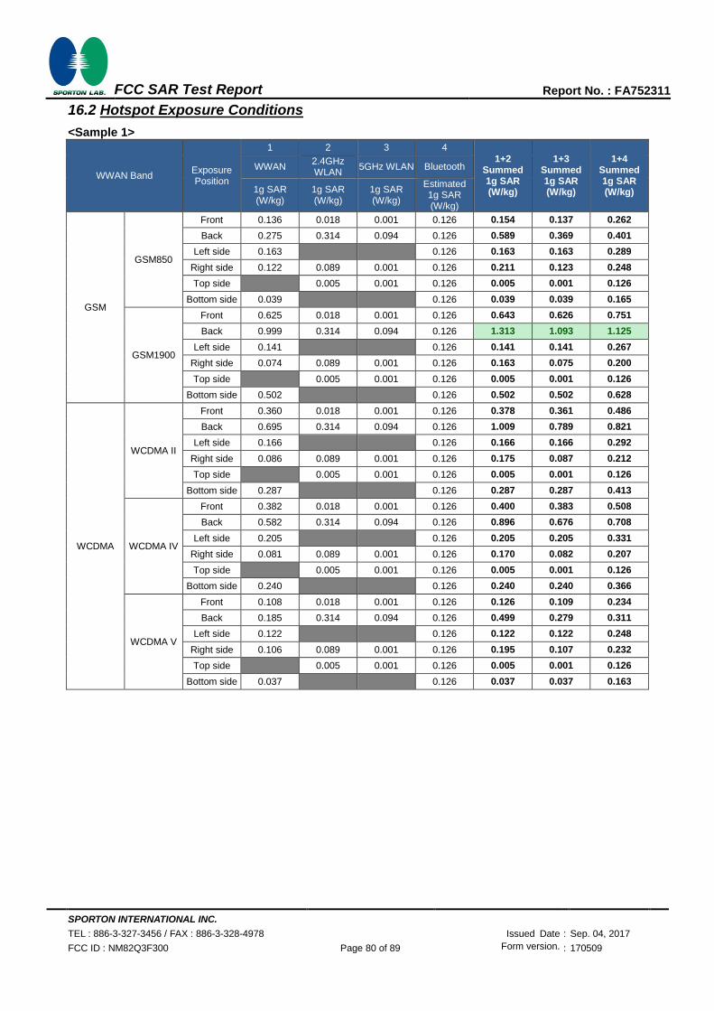
SPORTON INTERNATIONAL INC.
TEL : 886-3-327-3456 / FAX : 886-3-328-4978 Issued Date : Sep. 04, 2017
FCC ID : NM82Q3F300 Page 80 of 89 Form version. : 170509
FCC SAR Test Report Report No. : FA752311
16.2 Hotspot Exposure Conditions
<Sample 1>
WWAN Band Exposure Position
1 2 3 4
1+2 Summed 1g SAR (W/kg)
1+3 Summed 1g SAR (W/kg)
1+4 Summed 1g SAR (W/kg)
WWAN 2.4GHz WLAN
5GHz WLAN Bluetooth
1g SAR (W/kg)
1g SAR (W/kg)
1g SAR (W/kg)
Estimated 1g SAR (W/kg)
GSM
GSM850
Front 0.136 0.018 0.001 0.126 0.154 0.137 0.262
Back 0.275 0.314 0.094 0.126 0.589 0.369 0.401
Left side 0.163 0.000 0.000 0.126 0.163 0.163 0.289
Right side 0.122 0.089 0.001 0.126 0.211 0.123 0.248
Top side 0.000 0.005 0.001 0.126 0.005 0.001 0.126
Bottom side 0.039 0.000 0.000 0.126 0.039 0.039 0.165
GSM1900
Front 0.625 0.018 0.001 0.126 0.643 0.626 0.751
Back 0.999 0.314 0.094 0.126 1.313 1.093 1.125
Left side 0.141 0.000 0.000 0.126 0.141 0.141 0.267
Right side 0.074 0.089 0.001 0.126 0.163 0.075 0.200
Top side 0.000 0.005 0.001 0.126 0.005 0.001 0.126
Bottom side 0.502 0.000 0.000 0.126 0.502 0.502 0.628
WCDMA
WCDMA II
Front 0.360 0.018 0.001 0.126 0.378 0.361 0.486
Back 0.695 0.314 0.094 0.126 1.009 0.789 0.821
Left side 0.166 0.000 0.000 0.126 0.166 0.166 0.292
Right side 0.086 0.089 0.001 0.126 0.175 0.087 0.212
Top side 0.000 0.005 0.001 0.126 0.005 0.001 0.126
Bottom side 0.287 0.000 0.000 0.126 0.287 0.287 0.413
WCDMA IV
Front 0.382 0.018 0.001 0.126 0.400 0.383 0.508
Back 0.582 0.314 0.094 0.126 0.896 0.676 0.708
Left side 0.205 0.000 0.000 0.126 0.205 0.205 0.331
Right side 0.081 0.089 0.001 0.126 0.170 0.082 0.207
Top side 0.000 0.005 0.001 0.126 0.005 0.001 0.126
Bottom side 0.240 0.000 0.000 0.126 0.240 0.240 0.366
WCDMA V
Front 0.108 0.018 0.001 0.126 0.126 0.109 0.234
Back 0.185 0.314 0.094 0.126 0.499 0.279 0.311
Left side 0.122 0.000 0.000 0.126 0.122 0.122 0.248
Right side 0.106 0.089 0.001 0.126 0.195 0.107 0.232
Top side 0.000 0.005 0.001 0.126 0.005 0.001 0.126
Bottom side 0.037 0.000 0.000 0.126 0.037 0.037 0.163
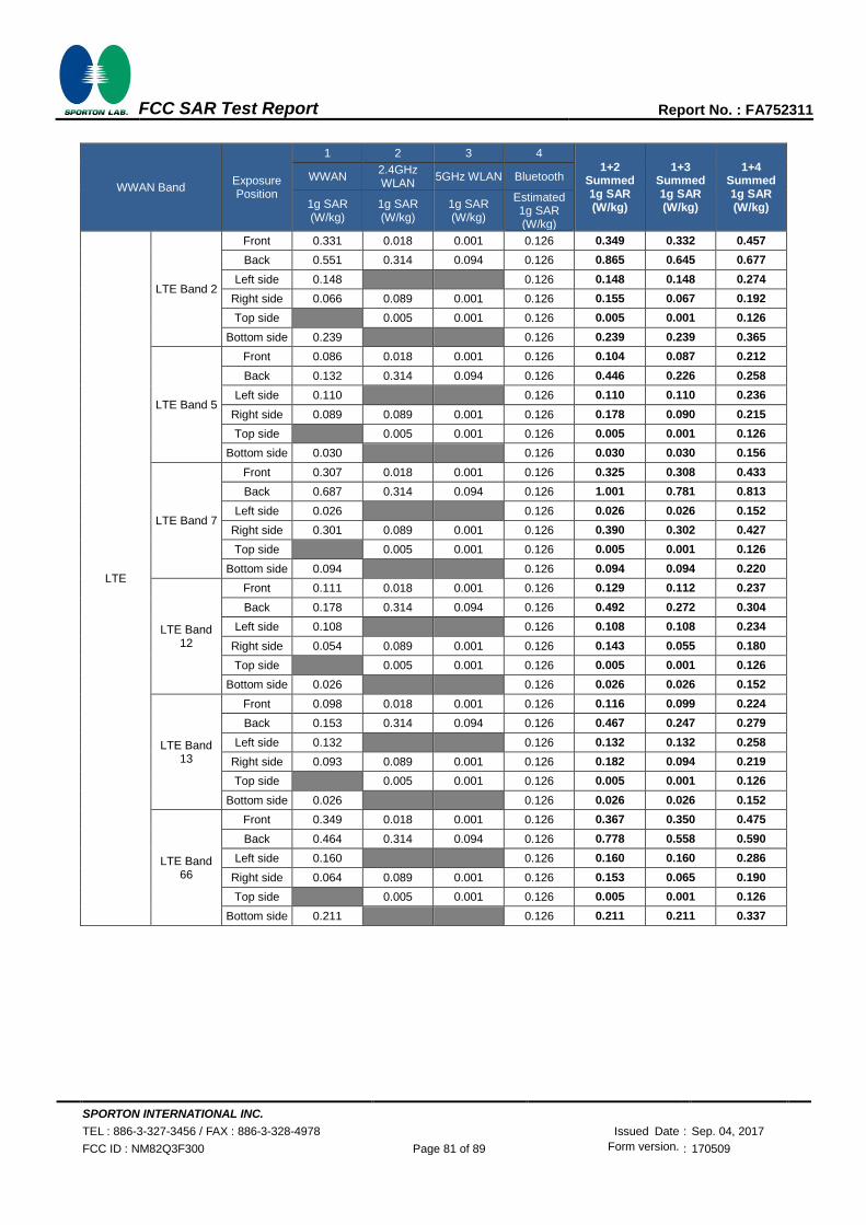
SPORTON INTERNATIONAL INC.
TEL : 886-3-327-3456 / FAX : 886-3-328-4978 Issued Date : Sep. 04, 2017
FCC ID : NM82Q3F300 Page 81 of 89 Form version. : 170509
FCC SAR Test Report Report No. : FA752311
WWAN Band Exposure Position
1 2 3 4
1+2 Summed 1g SAR (W/kg)
1+3 Summed 1g SAR (W/kg)
1+4 Summed 1g SAR (W/kg)
WWAN 2.4GHz WLAN
5GHz WLAN Bluetooth
1g SAR (W/kg)
1g SAR (W/kg)
1g SAR (W/kg)
Estimated 1g SAR (W/kg)
LTE
LTE Band 2
Front 0.331 0.018 0.001 0.126 0.349 0.332 0.457
Back 0.551 0.314 0.094 0.126 0.865 0.645 0.677
Left side 0.148 0.000 0.000 0.126 0.148 0.148 0.274
Right side 0.066 0.089 0.001 0.126 0.155 0.067 0.192
Top side 0.000 0.005 0.001 0.126 0.005 0.001 0.126
Bottom side 0.239 0.000 0.000 0.126 0.239 0.239 0.365
LTE Band 5
Front 0.086 0.018 0.001 0.126 0.104 0.087 0.212
Back 0.132 0.314 0.094 0.126 0.446 0.226 0.258
Left side 0.110 0.000 0.000 0.126 0.110 0.110 0.236
Right side 0.089 0.089 0.001 0.126 0.178 0.090 0.215
Top side 0.000 0.005 0.001 0.126 0.005 0.001 0.126
Bottom side 0.030 0.000 0.000 0.126 0.030 0.030 0.156
LTE Band 7
Front 0.307 0.018 0.001 0.126 0.325 0.308 0.433
Back 0.687 0.314 0.094 0.126 1.001 0.781 0.813
Left side 0.026 0.000 0.000 0.126 0.026 0.026 0.152
Right side 0.301 0.089 0.001 0.126 0.390 0.302 0.427
Top side 0.000 0.005 0.001 0.126 0.005 0.001 0.126
Bottom side 0.094 0.000 0.000 0.126 0.094 0.094 0.220
LTE Band 12
Front 0.111 0.018 0.001 0.126 0.129 0.112 0.237
Back 0.178 0.314 0.094 0.126 0.492 0.272 0.304
Left side 0.108 0.000 0.000 0.126 0.108 0.108 0.234
Right side 0.054 0.089 0.001 0.126 0.143 0.055 0.180
Top side 0.000 0.005 0.001 0.126 0.005 0.001 0.126
Bottom side 0.026 0.000 0.000 0.126 0.026 0.026 0.152
LTE Band 13
Front 0.098 0.018 0.001 0.126 0.116 0.099 0.224
Back 0.153 0.314 0.094 0.126 0.467 0.247 0.279
Left side 0.132 0.000 0.000 0.126 0.132 0.132 0.258
Right side 0.093 0.089 0.001 0.126 0.182 0.094 0.219
Top side 0.000 0.005 0.001 0.126 0.005 0.001 0.126
Bottom side 0.026 0.000 0.000 0.126 0.026 0.026 0.152
LTE Band 66
Front 0.349 0.018 0.001 0.126 0.367 0.350 0.475
Back 0.464 0.314 0.094 0.126 0.778 0.558 0.590
Left side 0.160 0.000 0.000 0.126 0.160 0.160 0.286
Right side 0.064 0.089 0.001 0.126 0.153 0.065 0.190
Top side 0.000 0.005 0.001 0.126 0.005 0.001 0.126
Bottom side 0.211 0.000 0.000 0.126 0.211 0.211 0.337

SPORTON INTERNATIONAL INC.
TEL : 886-3-327-3456 / FAX : 886-3-328-4978 Issued Date : Sep. 04, 2017
FCC ID : NM82Q3F300 Page 82 of 89 Form version. : 170509
FCC SAR Test Report Report No. : FA752311
<Sample 3>
WWAN Band Exposure Position
1 2 3 4 1+2
Summed 1g SAR (W/kg)
1+3 Summed 1g SAR (W/kg)
1+4 Summed 1g SAR (W/kg)
WWAN 2.4GHz WLAN
5GHz WLAN
Bluetooth
1g SAR (W/kg)
1g SAR (W/kg)
1g SAR (W/kg)
1g SAR (W/kg)
GSM
GSM850
Front 0.151 0.018 0.001 0.126 0.169 0.152 0.277
Back 0.211 0.314 0.094 0.126 0.525 0.305 0.337
Left side 0.155 0.000 0.000 0.126 0.155 0.155 0.281
Right side 0.149 0.089 0.001 0.126 0.238 0.150 0.275
Top side 0.000 0.005 0.001 0.126 0.005 0.001 0.126
Bottom side 0.045 0.000 0.000 0.126 0.045 0.045 0.171
GSM1900
Front 0.172 0.018 0.001 0.126 0.190 0.173 0.298
Back 0.340 0.314 0.094 0.126 0.654 0.434 0.466
Left side 0.060 0.000 0.000 0.126 0.060 0.060 0.186
Right side 0.035 0.089 0.001 0.126 0.124 0.036 0.161
Top side 0.000 0.005 0.001 0.126 0.005 0.001 0.126
Bottom side 0.150 0.000 0.000 0.126 0.150 0.150 0.276
WCDMA
WCDMA II
Front 0.219 0.018 0.001 0.126 0.237 0.220 0.345
Back 0.476 0.314 0.094 0.126 0.790 0.570 0.602
Left side 0.042 0.000 0.000 0.126 0.042 0.042 0.168
Right side 0.011 0.089 0.001 0.126 0.100 0.012 0.137
Top side 0.000 0.005 0.001 0.126 0.005 0.001 0.126
Bottom side 0.211 0.000 0.000 0.126 0.211 0.211 0.337
WCDMA IV
Front 0.278 0.018 0.001 0.126 0.296 0.279 0.404
Back 0.425 0.314 0.094 0.126 0.739 0.519 0.551
Left side 0.109 0.000 0.000 0.126 0.109 0.109 0.235
Right side 0.053 0.089 0.001 0.126 0.142 0.054 0.179
Top side 0.000 0.005 0.001 0.126 0.005 0.001 0.126
Bottom side 0.261 0.000 0.000 0.126 0.261 0.261 0.387
WCDMA V
Front 0.128 0.018 0.001 0.126 0.146 0.129 0.254
Back 0.177 0.314 0.094 0.126 0.491 0.271 0.303
Left side 0.123 0.000 0.000 0.126 0.123 0.123 0.249
Right side 0.123 0.089 0.001 0.126 0.212 0.124 0.249
Top side 0.000 0.005 0.001 0.126 0.005 0.001 0.126
Bottom side 0.040 0.000 0.000 0.126 0.040 0.040 0.166

SPORTON INTERNATIONAL INC.
TEL : 886-3-327-3456 / FAX : 886-3-328-4978 Issued Date : Sep. 04, 2017
FCC ID : NM82Q3F300 Page 83 of 89 Form version. : 170509
FCC SAR Test Report Report No. : FA752311
WWAN Band Exposure Position
1 2 3 4 1+2
Summed 1g SAR (W/kg)
1+3 Summed 1g SAR (W/kg)
1+4 Summed 1g SAR (W/kg)
WWAN 2.4GHz WLAN
5GHz WLAN
Bluetooth
1g SAR (W/kg)
1g SAR (W/kg)
1g SAR (W/kg)
1g SAR (W/kg)
LTE
LTE Band 2
Front 0.203 0.018 0.001 0.126 0.221 0.204 0.329
Back 0.407 0.314 0.094 0.126 0.721 0.501 0.533
Left side 0.041 0.000 0.000 0.126 0.041 0.041 0.167
Right side 0.010 0.089 0.001 0.126 0.099 0.011 0.136
Top side 0.000 0.005 0.001 0.126 0.005 0.001 0.126
Bottom side 0.228 0.000 0.000 0.126 0.228 0.228 0.354
LTE Band 5
Front 0.100 0.018 0.001 0.126 0.118 0.101 0.226
Back 0.121 0.314 0.094 0.126 0.435 0.215 0.247
Left side 0.097 0.000 0.000 0.126 0.097 0.097 0.223
Right side 0.097 0.089 0.001 0.126 0.186 0.098 0.223
Top side 0.000 0.005 0.001 0.126 0.005 0.001 0.126
Bottom side 0.032 0.000 0.000 0.126 0.032 0.032 0.158
LTE Band 7
Front 0.202 0.018 0.001 0.126 0.220 0.203 0.328
Back 0.382 0.314 0.094 0.126 0.696 0.476 0.508
Left side 0.011 0.000 0.000 0.126 0.011 0.011 0.137
Right side 0.258 0.089 0.001 0.126 0.347 0.259 0.384
Top side 0.000 0.005 0.001 0.126 0.005 0.001 0.126
Bottom side 0.071 0.000 0.000 0.126 0.071 0.071 0.197
LTE Band 12
Front 0.058 0.018 0.001 0.126 0.076 0.059 0.184
Back 0.086 0.314 0.094 0.126 0.400 0.180 0.212
Left side 0.057 0.000 0.000 0.126 0.057 0.057 0.183
Right side 0.028 0.089 0.001 0.126 0.117 0.029 0.154
Top side 0.000 0.005 0.001 0.126 0.005 0.001 0.126
Bottom side 0.013 0.000 0.000 0.126 0.013 0.013 0.139
LTE Band 13
Front 0.131 0.018 0.001 0.126 0.149 0.132 0.257
Back 0.146 0.314 0.094 0.126 0.460 0.240 0.272
Left side 0.143 0.000 0.000 0.126 0.143 0.143 0.269
Right side 0.126 0.089 0.001 0.126 0.215 0.127 0.252
Top side 0.000 0.005 0.001 0.126 0.005 0.001 0.126
Bottom side 0.030 0.000 0.000 0.126 0.030 0.030 0.156
LTE Band 66
Front 0.231 0.018 0.001 0.126 0.249 0.232 0.357
Back 0.379 0.314 0.094 0.126 0.693 0.473 0.505
Left side 0.091 0.000 0.000 0.126 0.091 0.091 0.217
Right side 0.047 0.089 0.001 0.126 0.136 0.048 0.173
Top side 0.000 0.005 0.001 0.126 0.005 0.001 0.126
Bottom side 0.205 0.000 0.000 0.126 0.205 0.205 0.331

SPORTON INTERNATIONAL INC.
TEL : 886-3-327-3456 / FAX : 886-3-328-4978 Issued Date : Sep. 04, 2017
FCC ID : NM82Q3F300 Page 84 of 89 Form version. : 170509
FCC SAR Test Report Report No. : FA752311
16.3 Body-Worn Accessory Exposure Conditions
<Sample 1>
WWAN Band Exposure Position
1 2 3 4
1+2 Summed 1g SAR (W/kg)
1+3 Summed 1g SAR (W/kg)
1+4 Summed 1g SAR (W/kg)
WWAN 2.4GHz WLAN
5GHz WLAN Bluetooth
1g SAR (W/kg)
1g SAR (W/kg)
1g SAR (W/kg)
Estimated 1g SAR (W/kg)
GSM
GSM850 Front 0.136 0.018 0.001 0.126 0.154 0.137 0.262
Back 0.275 0.314 0.003 0.126 0.589 0.278 0.401
GSM1900 Front 0.625 0.018 0.001 0.126 0.643 0.626 0.751
Back 0.999 0.314 0.003 0.126 1.313 1.002 1.125
WCDMA
WCDMA II Front 0.360 0.018 0.001 0.126 0.378 0.361 0.486
Back 0.695 0.314 0.003 0.126 1.009 0.698 0.821
WCDMA IV Front 0.382 0.018 0.001 0.126 0.400 0.383 0.508
Back 0.582 0.314 0.003 0.126 0.896 0.585 0.708
WCDMA V Front 0.108 0.018 0.001 0.126 0.126 0.109 0.234
Back 0.185 0.314 0.003 0.126 0.499 0.188 0.311
LTE
LTE Band 2 Front 0.331 0.018 0.001 0.126 0.349 0.332 0.457
Back 0.551 0.314 0.003 0.126 0.865 0.554 0.677
LTE Band 5 Front 0.086 0.018 0.001 0.126 0.104 0.087 0.212
Back 0.132 0.314 0.003 0.126 0.446 0.135 0.258
LTE Band 7 Front 0.307 0.018 0.001 0.126 0.325 0.308 0.433
Back 0.687 0.314 0.003 0.126 1.001 0.690 0.813
LTE Band 12
Front 0.111 0.018 0.001 0.126 0.129 0.112 0.237
Back 0.178 0.314 0.003 0.126 0.492 0.181 0.304
LTE Band 13
Front 0.098 0.018 0.001 0.126 0.116 0.099 0.224
Back 0.153 0.314 0.003 0.126 0.467 0.156 0.279
LTE Band 66
Front 0.349 0.018 0.001 0.126 0.367 0.350 0.475
Back 0.464 0.314 0.003 0.126 0.778 0.467 0.590

SPORTON INTERNATIONAL INC.
TEL : 886-3-327-3456 / FAX : 886-3-328-4978 Issued Date : Sep. 04, 2017
FCC ID : NM82Q3F300 Page 85 of 89 Form version. : 170509
FCC SAR Test Report Report No. : FA752311
<Sample 3>
WWAN Band Exposure Position
1 2 3 4 1+2
Summed 1g SAR (W/kg)
1+3 Summed 1g SAR (W/kg)
1+4 Summed 1g SAR (W/kg)
WWAN 2.4GHz WLAN
5GHz WLAN
Bluetooth
1g SAR (W/kg)
1g SAR (W/kg)
1g SAR (W/kg)
1g SAR (W/kg)
GSM
GSM850 Front 0.151 0.018 0.001 0.126 0.169 0.152 0.277
Back 0.211 0.314 0.094 0.126 0.525 0.305 0.337
GSM1900 Front 0.172 0.018 0.001 0.126 0.190 0.173 0.298
Back 0.340 0.314 0.094 0.126 0.654 0.434 0.466
WCDMA
WCDMA II Front 0.219 0.018 0.001 0.126 0.237 0.220 0.345
Back 0.476 0.314 0.094 0.126 0.790 0.570 0.602
WCDMA IV Front 0.278 0.018 0.001 0.126 0.296 0.279 0.404
Back 0.425 0.314 0.094 0.126 0.739 0.519 0.551
WCDMA V Front 0.128 0.018 0.001 0.126 0.146 0.129 0.254
Back 0.177 0.314 0.094 0.126 0.491 0.271 0.303
LTE
LTE Band 2 Front 0.203 0.018 0.001 0.126 0.221 0.204 0.329
Back 0.407 0.314 0.094 0.126 0.721 0.501 0.533
LTE Band 5 Front 0.100 0.018 0.001 0.126 0.118 0.101 0.226
Back 0.121 0.314 0.094 0.126 0.435 0.215 0.247
LTE Band 7 Front 0.202 0.018 0.001 0.126 0.220 0.203 0.328
Back 0.382 0.314 0.094 0.126 0.696 0.476 0.508
LTE Band 12
Front 0.058 0.018 0.001 0.126 0.076 0.059 0.184
Back 0.086 0.314 0.094 0.126 0.400 0.180 0.212
LTE Band 13
Front 0.131 0.018 0.001 0.126 0.149 0.132 0.257
Back 0.146 0.314 0.094 0.126 0.460 0.240 0.272
LTE Band 66
Front 0.231 0.018 0.001 0.126 0.249 0.232 0.357
Back 0.379 0.314 0.094 0.126 0.693 0.473 0.505
Test Engineer: Wilson Lin Steven Chang Tommy Chen and Iran Wang
SPORTON INTERNATIONAL INC.
TEL : 886-3-327-3456 / FAX : 886-3-328-4978 Issued Date : Sep. 04, 2017
FCC ID : NM82Q3F300 Page 86 of 89 Form version. : 170509
FCC SAR Test Report Report No. : FA752311
17. Uncertainty Assessment
The component of uncertainly may generally be categorized according to the methods used to evaluate them. The evaluation of uncertainly by the statistical analysis of a series of observations is termed a Type An evaluation of uncertainty. The evaluation of uncertainty by means other than the statistical analysis of a series of observation is termed a Type B evaluation of uncertainty. Each component of uncertainty, however evaluated, is represented by an estimated standard deviation, termed standard uncertainty, which is determined by the positive square root of the estimated variance.
A Type A evaluation of standard uncertainty may be based on any valid statistical method for treating data. This includes calculating the standard deviation of the mean of a series of independent observations; using the method of least squares to fit a curve to the data in order to estimate the parameter of the curve and their standard deviations; or carrying out an analysis of variance in order to identify and quantify random effects in certain kinds of measurement.
A type B evaluation of standard uncertainty is typically based on scientific judgment using all of the relevant information available. These may include previous measurement data, experience, and knowledge of the behavior and properties of relevant materials and instruments, manufacture’s specification, data provided in calibration reports and uncertainties assigned to reference data taken from handbooks. Broadly speaking, the uncertainty is either obtained from an outdoor source or obtained from an assumed distribution, such as the normal distribution, rectangular or triangular distributions indicated in table below.
Uncertainty Distributions Normal Rectangular Triangular U-Shape
Multi-plying Factor(a)
1/k(b)
1/√3 1/√6 1/√2
(a) standard uncertainty is determined as the product of the multiplying factor and the estimated range of
variations in the measured quantity
(b) κ is the coverage factor
Table 17.1. Standard Uncertainty for Assumed Distribution The combined standard uncertainty of the measurement result represents the estimated standard deviation of the result. It is obtained by combining the individual standard uncertainties of both Type A and Type B evaluation using the usual “root-sum-squares” (RSS) methods of combining standard deviations by taking the positive square root of the estimated variances. Expanded uncertainty is a measure of uncertainty that defines an interval about the measurement result within which the measured value is confidently believed to lie. It is obtained by multiplying the combined standard uncertainty by a coverage factor. Typically, the coverage factor ranges from 2 to 3. Using a coverage factor allows the true value of a measured quantity to be specified with a defined probability within the specified uncertainty range. For purpose of this document, a coverage factor two is used, which corresponds to confidence interval of about 95 %. The DASY uncertainty Budget is shown in the following tables.

SPORTON INTERNATIONAL INC.
TEL : 886-3-327-3456 / FAX : 886-3-328-4978 Issued Date : Sep. 04, 2017
FCC ID : NM82Q3F300 Page 87 of 89 Form version. : 170509
FCC SAR Test Report Report No. : FA752311
Error Description Uncertainty
Value (±%)
Probability Divisor (Ci) 1g
(Ci) 10g
Standard Uncertainty
(1g) (±%)
Standard Uncertainty (10g) (±%)
Measurement System
Probe Calibration 6.00 N 1 1 1 6.0 6.0
Axial Isotropy 4.70 R 1.732 0.7 0.7 1.9 1.9
Hemispherical Isotropy 9.60 R 1.732 0.7 0.7 3.9 3.9
Boundary Effects 1.00 R 1.732 1 1 0.6 0.6
Linearity 4.70 R 1.732 1 1 2.7 2.7
System Detection Limits 1.00 R 1.732 1 1 0.6 0.6
Modulation Response 4.68 R 1.732 1 1 2.7 2.7
Readout Electronics 0.30 N 1 1 1 0.3 0.3
Response Time 0.00 R 1.732 1 1 0.0 0.0
Integration Time 2.60 R 1.732 1 1 1.5 1.5
RF Ambient Noise 3.00 R 1.732 1 1 1.7 1.7
RF Ambient Reflections 3.00 R 1.732 1 1 1.7 1.7
Probe Positioner 0.40 R 1.732 1 1 0.2 0.2
Probe Positioning 2.90 R 1.732 1 1 1.7 1.7
Max. SAR Eval. 2.00 R 1.732 1 1 1.2 1.2
Test Sample Related
Device Positioning 3.03 N 1 1 1 3.0 3.0
Device Holder 3.60 N 1 1 1 3.6 3.6
Power Drift 5.00 R 1.732 1 1 2.9 2.9
Power Scaling 0.00 R 1.732 1 1 0.0 0.0
Phantom and Setup
Phantom Uncertainty 6.10 R 1.732 1 1 3.5 3.5
SAR correction 0.00 R 1.732 1 0.84 0.0 0.0
Liquid Conductivity Repeatability 0.03 N 1 0.78 0.71 0.0 0.0
Liquid Conductivity (target) 5.00 R 1.732 0.78 0.71 2.3 2.0
Liquid Conductivity (mea.) 2.50 R 1.732 0.78 0.71 1.1 1.0
Temp. unc. - Conductivity 3.68 R 1.732 0.78 0.71 1.7 1.5
Liquid Permittivity Repeatability 0.02 N 1 0.23 0.26 0.0 0.0
Liquid Permittivity (target) 5.00 R 1.732 0.23 0.26 0.7 0.8
Liquid Permittivity (mea.) 2.50 R 1.732 0.23 0.26 0.3 0.4
Temp. unc. - Permittivity 0.84 R 1.732 0.23 0.26 0.1 0.1
Combined Std. Uncertainty 11.6% 11.6%
Coverage Factor for 95 % K=2 K=2
Expanded STD Uncertainty 23.2% 23.1%
Table 17.2. Uncertainty Budget for frequency range 300 MHz to 3 GHz

SPORTON INTERNATIONAL INC.
TEL : 886-3-327-3456 / FAX : 886-3-328-4978 Issued Date : Sep. 04, 2017
FCC ID : NM82Q3F300 Page 88 of 89 Form version. : 170509
FCC SAR Test Report Report No. : FA752311
Error Description Uncertainty
Value (±%)
Probability Divisor (Ci) 1g
(Ci) 10g
Standard Uncertainty
(1g) (±%)
Standard Uncertainty (10g) (±%)
Measurement System
Probe Calibration 6.55 N 1 1 1 6.6 6.6
Axial Isotropy 4.70 R 1.732 0.7 0.7 1.9 1.9
Hemispherical Isotropy 9.60 R 1.732 0.7 0.7 3.9 3.9
Boundary Effects 2.00 R 1.732 1 1 1.2 1.2
Linearity 4.70 R 1.732 1 1 2.7 2.7
System Detection Limits 1.00 R 1.732 1 1 0.6 0.6
Modulation Response 4.68 R 1.732 1 1 2.7 2.7
Readout Electronics 0.30 N 1 1 1 0.3 0.3
Response Time 0.00 R 1.732 1 1 0.0 0.0
Integration Time 2.60 R 1.732 1 1 1.5 1.5
RF Ambient Noise 3.00 R 1.732 1 1 1.7 1.7
RF Ambient Reflections 3.00 R 1.732 1 1 1.7 1.7
Probe Positioner 0.40 R 1.732 1 1 0.2 0.2
Probe Positioning 6.70 R 1.732 1 1 3.9 3.9
Max. SAR Eval. 4.00 R 1.732 1 1 2.3 2.3
Test Sample Related
Device Positioning 3.03 N 1 1 1 3.0 3.0
Device Holder 3.60 N 1 1 1 3.6 3.6
Power Drift 5.00 R 1.732 1 1 2.9 2.9
Power Scaling 0.00 R 1.732 1 1 0.0 0.0
Phantom and Setup
Phantom Uncertainty 6.60 R 1.732 1 1 3.8 3.8
SAR correction 0.00 R 1.732 1 0.84 0.0 0.0
Liquid Conductivity Repeatability 0.03 N 1 0.78 0.71 0.0 0.0
Liquid Conductivity (target) 5.00 R 1.732 0.78 0.71 2.3 2.0
Liquid Conductivity (mea.) 2.50 R 1.732 0.78 0.71 1.1 1.0
Temp. unc. - Conductivity 3.68 R 1.732 0.78 0.71 1.7 1.5
Liquid Permittivity Repeatability 0.02 N 1 0.23 0.26 0.0 0.0
Liquid Permittivity (target) 5.00 R 1.732 0.23 0.26 0.7 0.8
Liquid Permittivity (mea.) 2.50 R 1.732 0.23 0.26 0.3 0.4
Temp. unc. - Permittivity 0.84 R 1.732 0.23 0.26 0.1 0.1
Combined Std. Uncertainty 12.7% 12.6%
Coverage Factor for 95 % K=2 K=2
Expanded STD Uncertainty 25.4% 25.3%
Table 17.3. Uncertainty Budget for frequency range 3 GHz to 6 GHz

SPORTON INTERNATIONAL INC.
TEL : 886-3-327-3456 / FAX : 886-3-328-4978 Issued Date : Sep. 04, 2017
FCC ID : NM82Q3F300 Page 89 of 89 Form version. : 170509
FCC SAR Test Report Report No. : FA752311
18. References
[1] FCC 47 CFR Part 2 “Frequency Allocations and Radio Treaty Matters; General Rules and
Regulations”
[2] ANSI/IEEE Std. C95.1-1992, “IEEE Standard for Safety Levels with Respect to Human Exposure
to Radio Frequency Electromagnetic Fields, 3 kHz to 300 GHz”, September 1992
[3] IEEE Std. 1528-2013, “IEEE Recommended Practice for Determining the Peak Spatial-Average
Specific Absorption Rate (SAR) in the Human Head from Wireless Communications Devices:
Measurement Techniques”, Sep 2013
[4] SPEAG DASY System Handbook
[5] FCC KDB 248227 D01 v02r02, “SAR Guidance for IEEE 802.11 (WiFi) Transmitters”, Oct 2015.
[6] FCC KDB 447498 D01 v06, “Mobile and Portable Device RF Exposure Procedures and
Equipment Authorization Policies”, Oct 2015
[7] FCC KDB 648474 D04 v01r03, “SAR Evaluation Considerations for Wireless Handsets”, Oct
2015.
[8] FCC KDB 941225 D01 v03r01, “3G SAR MEAUREMENT PROCEDURES”, Oct 2015
[9] FCC KDB 941225 D05 v02r05, “SAR Evaluation Considerations for LTE Devices”, Dec 2015
[10] FCC KDB 941225 D05A v01r02, “Rel. 10 LTE SAR Test Guidance and KDB Inquiries”, Oct 2015
[11] FCC KDB 941225 D06 v02r01, "SAR Evaluation Procedures for Portable Devices with Wireless
Router Capabilities", Oct 2015.
[12] FCC KDB 865664 D01 v01r04, "SAR Measurement Requirements for 100 MHz to 6 GHz", Aug
2015.
[13] FCC KDB 865664 D02 v01r02, “RF Exposure Compliance Reporting and Documentation
Considerations” Oct 2015.

SPORTON INTERNATIONAL INC.
TEL : 886-3-327-3456 / FAX : 886-3-328-4978 Issued Date : Sep. 04, 2017
FCC ID : NM82Q3F300 Page A1 of A1 Form version. : 170125
FCC SAR Test Report Report No. : FA752311
Appendix A. Plots of System Performance Check
The plots are shown as follows.

Test Laboratory: Sporton International Inc. SAR/HAC Testing Lab Date: 2017/6/13
System Check_Head_750MHz
DUT: D750V3-1012
Communication System: CW; Frequency: 750 MHz;Duty Cycle: 1:1
Medium: HSL_750_170613 Medium parameters used: f = 750 MHz; σ = 0.898 S/m; εr = 40.872; ρ
= 1000 kg/m3
23.7 22.7
DASY5 Configuration:
- Probe: ES3DV3 - SN3169; ConvF(6.07, 6.07, 6.07); Calibrated: 2017/5/11;
- Sensor-Surface: 3mm (Mechanical Surface Detection)
- Electronics: DAE4 Sn1399; Calibrated: 2016/11/17
- Phantom: SAM_Left; Type: QD000P40CD; Serial: TP:1431
- Measurement SW: DASY52, Version 52.8 (8);SEMCAD X Version 14.6.10 (7373)
Pin=250mW/Area Scan (61x61x1): Interpolated grid: dx=1.500 mm, dy=1.500 mm
Maximum value of SAR (interpolated) = 2.84 W/kg
Pin=250mW/Zoom Scan (5x5x7)/Cube 0: Measurement grid: dx=8mm, dy=8mm, dz=5mm
Reference Value = 59.10 V/m; Power Drift = 0.00 dB
Peak SAR (extrapolated) = 3.63 W/kg
SAR(1 g) = 2.17 W/kg; SAR(10 g) = 1.42 W/kg
Maximum value of SAR (measured) = 2.83 W/kg
0 dB = 2.83 W/kg = 4.52 dBW/kg
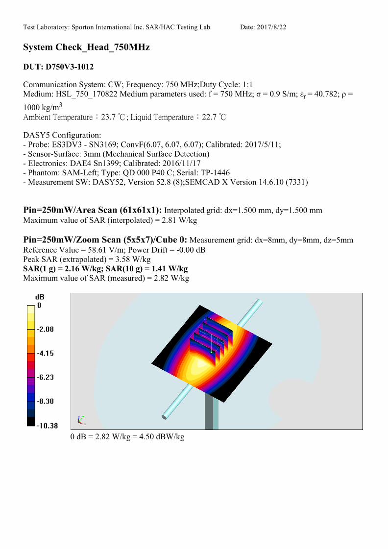
Test Laboratory: Sporton International Inc. SAR/HAC Testing Lab Date: 2017/8/22
System Check_Head_750MHz
DUT: D750V31012
Communication System: CW; Frequency: 750 MHz;Duty Cycle: 1:1 Medium: HSL_750_170822 Medium parameters used: f = 750 MHz; σ = 0.9 S/m; εr = 40.782; ρ =
1000 kg/m3 Ambient Temperature:23.7 ; Liquid Temperature:22.7
DASY5 Configuration: Probe: ES3DV3 SN3169; ConvF(6.07, 6.07, 6.07); Calibrated: 2017/5/11; SensorSurface: 3mm (Mechanical Surface Detection) Electronics: DAE4 Sn1399; Calibrated: 2016/11/17 Phantom: SAMLeft; Type: QD 000 P40 C; Serial: TP1446 Measurement SW: DASY52, Version 52.8 (8);SEMCAD X Version 14.6.10 (7331)
Pin=250mW/Area Scan (61x61x1): Interpolated grid: dx=1.500 mm, dy=1.500 mmMaximum value of SAR (interpolated) = 2.81 W/kg
Pin=250mW/Zoom Scan (5x5x7)/Cube 0: Measurement grid: dx=8mm, dy=8mm, dz=5mmReference Value = 58.61 V/m; Power Drift = 0.00 dBPeak SAR (extrapolated) = 3.58 W/kgSAR(1 g) = 2.16 W/kg; SAR(10 g) = 1.41 W/kgMaximum value of SAR (measured) = 2.82 W/kg
0 dB = 2.82 W/kg = 4.50 dBW/kg

Test Laboratory: Sporton International Inc. SAR/HAC Testing Lab Date: 2017/6/11
System Check_Body_750MHz
DUT: D750V3-1012
Communication System: CW; Frequency: 750 MHz;Duty Cycle: 1:1Medium: MSL_750_170611 Medium parameters used: f = 750 MHz; σ = 0.96 S/m; εr = 55.486; ρ =1000 kg/m3 Ambient Temperature:23.4 ; Liquid Temperature:22.4
DASY5 Configuration:- Probe: ES3DV3 - SN3270; ConvF(6.09, 6.09, 6.09); Calibrated: 2016/8/26; - Sensor-Surface: 3mm (Mechanical Surface Detection)- Electronics: DAE4 Sn778; Calibrated: 2017/5/22- Phantom: SAM-Left; Type: QD 000 P40 C; Serial: TP-1446- Measurement SW: DASY52, Version 52.8 (8);SEMCAD X Version 14.6.10 (7331)
Pin=250mW/Area Scan (61x61x1): Interpolated grid: dx=1.500 mm, dy=1.500 mmMaximum value of SAR (interpolated) = 2.61 W/kg
Pin=250mW/Zoom Scan (5x5x7)/Cube 0: Measurement grid: dx=8mm, dy=8mm, dz=5mmReference Value = 53.61 V/m; Power Drift = -0.06 dBPeak SAR (extrapolated) = 3.32 W/kgSAR(1 g) = 2.27 W/kg; SAR(10 g) = 1.53 W/kgMaximum value of SAR (measured) = 2.64 W/kg
0 dB = 2.64 W/kg = 4.22 dBW/kg
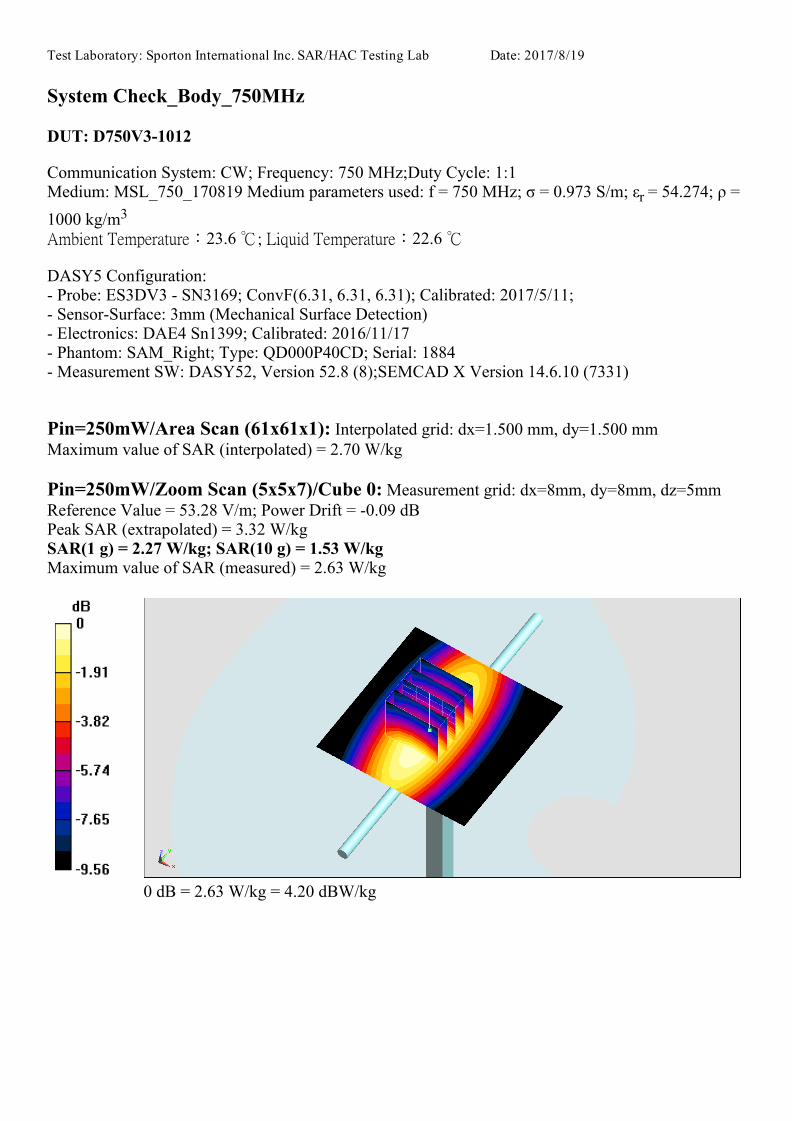
Test Laboratory: Sporton International Inc. SAR/HAC Testing Lab Date: 2017/8/19
System Check_Body_750MHz
DUT: D750V31012
Communication System: CW; Frequency: 750 MHz;Duty Cycle: 1:1 Medium: MSL_750_170819 Medium parameters used: f = 750 MHz; σ = 0.973 S/m; εr = 54.274; ρ =
1000 kg/m3 Ambient Temperature:23.6 ; Liquid Temperature:22.6
DASY5 Configuration: Probe: ES3DV3 SN3169; ConvF(6.31, 6.31, 6.31); Calibrated: 2017/5/11; SensorSurface: 3mm (Mechanical Surface Detection) Electronics: DAE4 Sn1399; Calibrated: 2016/11/17 Phantom: SAM_Right; Type: QD000P40CD; Serial: 1884 Measurement SW: DASY52, Version 52.8 (8);SEMCAD X Version 14.6.10 (7331)
Pin=250mW/Area Scan (61x61x1): Interpolated grid: dx=1.500 mm, dy=1.500 mmMaximum value of SAR (interpolated) = 2.70 W/kg
Pin=250mW/Zoom Scan (5x5x7)/Cube 0: Measurement grid: dx=8mm, dy=8mm, dz=5mmReference Value = 53.28 V/m; Power Drift = 0.09 dBPeak SAR (extrapolated) = 3.32 W/kgSAR(1 g) = 2.27 W/kg; SAR(10 g) = 1.53 W/kgMaximum value of SAR (measured) = 2.63 W/kg
0 dB = 2.63 W/kg = 4.20 dBW/kg

Test Laboratory: Sporton International Inc. SAR/HAC Testing Lab Date: 2017/6/12
System Check_Head_835MHz
DUT: D835V2-499
Communication System: CW; Frequency: 835 MHz;Duty Cycle: 1:1
Medium: HSL_850_170612 Medium parameters used: f = 835 MHz; σ = 0.901 S/m; εr = 43.151; ρ
= 1000 kg/m3
23.2 22.2
DASY5 Configuration:
- Probe: ES3DV3 - SN3169; ConvF(5.99, 5.99, 5.99); Calibrated: 2017/5/11;
- Sensor-Surface: 3mm (Mechanical Surface Detection)
- Electronics: DAE4 Sn1399; Calibrated: 2016/11/17
- Phantom: SAM_Left; Type: QD000P40CD; Serial: TP:1431
- Measurement SW: DASY52, Version 52.8 (8);SEMCAD X Version 14.6.10 (7373)
Pin=250mW/Area Scan (61x61x1): Interpolated grid: dx=1.500 mm, dy=1.500 mm
Maximum value of SAR (interpolated) = 2.81 W/kg
Pin=250mW/Zoom Scan (5x5x7)/Cube 0: Measurement grid: dx=8mm, dy=8mm, dz=5mm
Reference Value = 57.09 V/m; Power Drift = 0.01 dB
Peak SAR (extrapolated) = 3.57 W/kg
SAR(1 g) = 2.39 W/kg; SAR(10 g) = 1.58 W/kg
Maximum value of SAR (measured) = 2.78 W/kg
0 dB = 2.78 W/kg = 4.44 dBW/kg
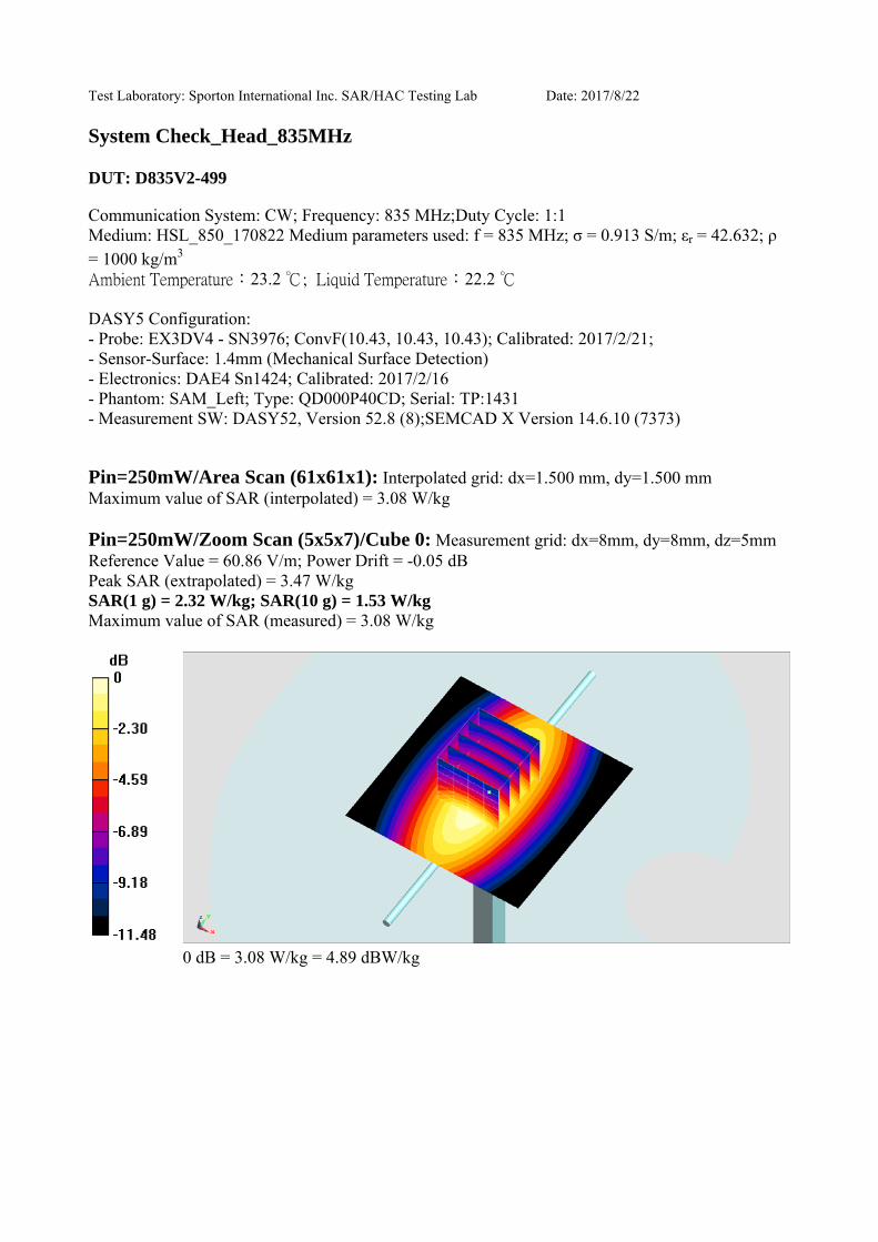
Test Laboratory: Sporton International Inc. SAR/HAC Testing Lab Date: 2017/8/22
System Check_Head_835MHz
DUT: D835V2-499
Communication System: CW; Frequency: 835 MHz;Duty Cycle: 1:1Medium: HSL_850_170822 Medium parameters used: f = 835 MHz; σ = 0.913 S/m; εr = 42.632; ρ = 1000 kg/m3
23.2 22.2
DASY5 Configuration:- Probe: EX3DV4 - SN3976; ConvF(10.43, 10.43, 10.43); Calibrated: 2017/2/21; - Sensor-Surface: 1.4mm (Mechanical Surface Detection)- Electronics: DAE4 Sn1424; Calibrated: 2017/2/16- Phantom: SAM_Left; Type: QD000P40CD; Serial: TP:1431- Measurement SW: DASY52, Version 52.8 (8);SEMCAD X Version 14.6.10 (7373)
Pin=250mW/Area Scan (61x61x1): Interpolated grid: dx=1.500 mm, dy=1.500 mmMaximum value of SAR (interpolated) = 3.08 W/kg
Pin=250mW/Zoom Scan (5x5x7)/Cube 0: Measurement grid: dx=8mm, dy=8mm, dz=5mmReference Value = 60.86 V/m; Power Drift = -0.05 dBPeak SAR (extrapolated) = 3.47 W/kgSAR(1 g) = 2.32 W/kg; SAR(10 g) = 1.53 W/kgMaximum value of SAR (measured) = 3.08 W/kg
0 dB = 3.08 W/kg = 4.89 dBW/kg
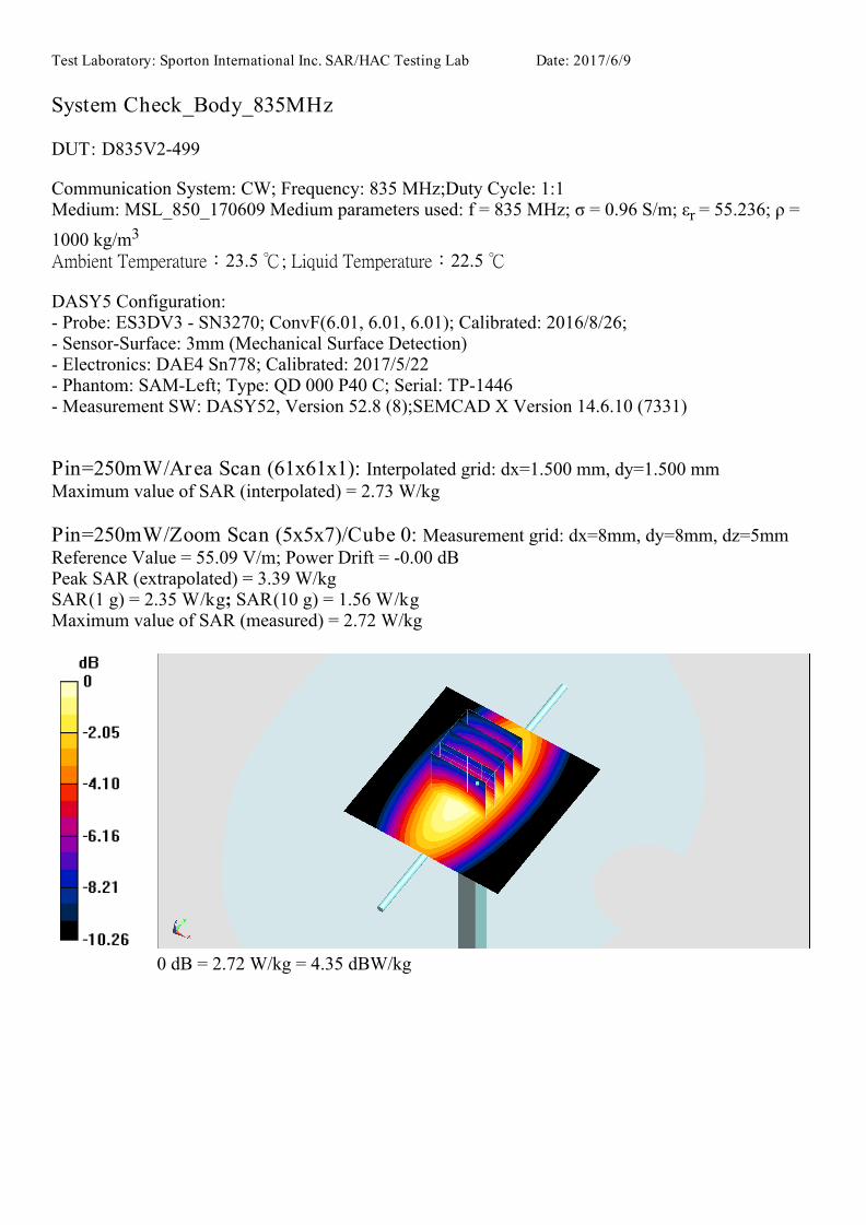
Test Laboratory: Sporton International Inc. SAR/HAC Testing Lab Date: 2017/6/9
System Check_Body_835MHz
DUT: D835V2-499
Communication System: CW; Frequency: 835 MHz;Duty Cycle: 1:1Medium: MSL_850_170609 Medium parameters used: f = 835 MHz; σ = 0.96 S/m; εr = 55.236; ρ =1000 kg/m3 Ambient Temperature:23.5 ; Liquid Temperature:22.5
DASY5 Configuration:- Probe: ES3DV3 - SN3270; ConvF(6.01, 6.01, 6.01); Calibrated: 2016/8/26; - Sensor-Surface: 3mm (Mechanical Surface Detection)- Electronics: DAE4 Sn778; Calibrated: 2017/5/22- Phantom: SAM-Left; Type: QD 000 P40 C; Serial: TP-1446- Measurement SW: DASY52, Version 52.8 (8);SEMCAD X Version 14.6.10 (7331)
Pin=250mW/Area Scan (61x61x1): Interpolated grid: dx=1.500 mm, dy=1.500 mmMaximum value of SAR (interpolated) = 2.73 W/kg
Pin=250mW/Zoom Scan (5x5x7)/Cube 0: Measurement grid: dx=8mm, dy=8mm, dz=5mmReference Value = 55.09 V/m; Power Drift = -0.00 dBPeak SAR (extrapolated) = 3.39 W/kgSAR(1 g) = 2.35 W/kg; SAR(10 g) = 1.56 W/kgMaximum value of SAR (measured) = 2.72 W/kg
0 dB = 2.72 W/kg = 4.35 dBW/kg
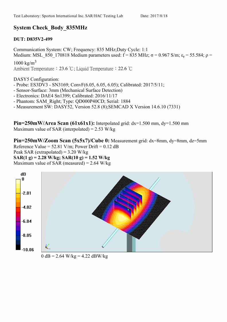
Test Laboratory: Sporton International Inc. SAR/HAC Testing Lab Date: 2017/8/18
System Check_Body_835MHz
DUT: D835V2499
Communication System: CW; Frequency: 835 MHz;Duty Cycle: 1:1Medium: MSL_850_170818 Medium parameters used: f = 835 MHz; σ = 0.967 S/m; εr = 55.584; ρ =1000 kg/m3 Ambient Temperature:23.6 ; Liquid Temperature:22.6
DASY5 Configuration: Probe: ES3DV3 SN3169; ConvF(6.05, 6.05, 6.05); Calibrated: 2017/5/11; SensorSurface: 3mm (Mechanical Surface Detection) Electronics: DAE4 Sn1399; Calibrated: 2016/11/17 Phantom: SAM_Right; Type: QD000P40CD; Serial: 1884 Measurement SW: DASY52, Version 52.8 (8);SEMCAD X Version 14.6.10 (7331)
Pin=250mW/Area Scan (61x61x1): Interpolated grid: dx=1.500 mm, dy=1.500 mmMaximum value of SAR (interpolated) = 2.53 W/kg
Pin=250mW/Zoom Scan (5x5x7)/Cube 0: Measurement grid: dx=8mm, dy=8mm, dz=5mmReference Value = 52.81 V/m; Power Drift = 0.12 dBPeak SAR (extrapolated) = 3.20 W/kgSAR(1 g) = 2.28 W/kg; SAR(10 g) = 1.52 W/kgMaximum value of SAR (measured) = 2.64 W/kg
0 dB = 2.64 W/kg = 4.22 dBW/kg

Test Laboratory: Sporton International Inc. SAR/HAC Testing Lab Date: 2017/6/7
System Check_Head_1750MHz
DUT: D1750V2-1068
Communication System: CW; Frequency: 1750 MHz;Duty Cycle: 1:1 Medium: HSL_1750_170607 Medium parameters used: f = 1750 MHz; σ = 1.355 S/m; εr = 41.553; ρ
= 1000 kg/m3 Ambient Temperature:23.2 ; Liquid Temperature:22.2
DASY5 Configuration:- Probe: ES3DV3 SN3270; ConvF(5.21, 5.21, 5.21); Calibrated: 2016/8/26; - Sensor-Surface: 3mm (Mechanical Surface Detection)- Electronics: DAE4 Sn916; Calibrated: 2016/12/15 - Phantom: SAM_Right; Type: QD000P40CD; Serial: 1884 - Measurement SW: DASY52, Version 52.8 (8);SEMCAD X Version 14.6.10 (7331)
Pin=250mW/Area Scan (61x61x1): Interpolated grid: dx=1.500 mm, dy=1.500 mmMaximum value of SAR (interpolated) = 11.3 W/kg
Pin=250mW/Zoom Scan (5x5x7)/Cube 0: Measurement grid: dx=8mm, dy=8mm, dz=5mmReference Value = 92.54 V/m; Power Drift = -0.07 dBPeak SAR (extrapolated) = 15.0 W/kgSAR(1 g) = 8.86 W/kg; SAR(10 g) = 4.85 W/kgMaximum value of SAR (measured) = 10.8 W/kg
0 dB = 10.8 W/kg = 10.33 dBW/kg
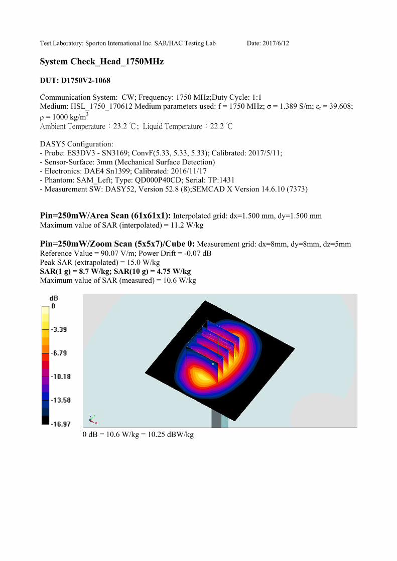
Test Laboratory: Sporton International Inc. SAR/HAC Testing Lab Date: 2017/6/12
System Check_Head_1750MHz
DUT: D1750V2-1068
Communication System: CW; Frequency: 1750 MHz;Duty Cycle: 1:1
Medium: HSL_1750_170612 Medium parameters used: f = 1750 MHz; σ = 1.389 S/m; εr = 39.608;
ρ = 1000 kg/m3
23.2 22.2
DASY5 Configuration:
- Probe: ES3DV3 - SN3169; ConvF(5.33, 5.33, 5.33); Calibrated: 2017/5/11;
- Sensor-Surface: 3mm (Mechanical Surface Detection)
- Electronics: DAE4 Sn1399; Calibrated: 2016/11/17
- Phantom: SAM_Left; Type: QD000P40CD; Serial: TP:1431
- Measurement SW: DASY52, Version 52.8 (8);SEMCAD X Version 14.6.10 (7373)
Pin=250mW/Area Scan (61x61x1): Interpolated grid: dx=1.500 mm, dy=1.500 mm
Maximum value of SAR (interpolated) = 11.2 W/kg
Pin=250mW/Zoom Scan (5x5x7)/Cube 0: Measurement grid: dx=8mm, dy=8mm, dz=5mm
Reference Value = 90.07 V/m; Power Drift = -0.07 dB
Peak SAR (extrapolated) = 15.0 W/kg
SAR(1 g) = 8.7 W/kg; SAR(10 g) = 4.75 W/kg
Maximum value of SAR (measured) = 10.6 W/kg
0 dB = 10.6 W/kg = 10.25 dBW/kg
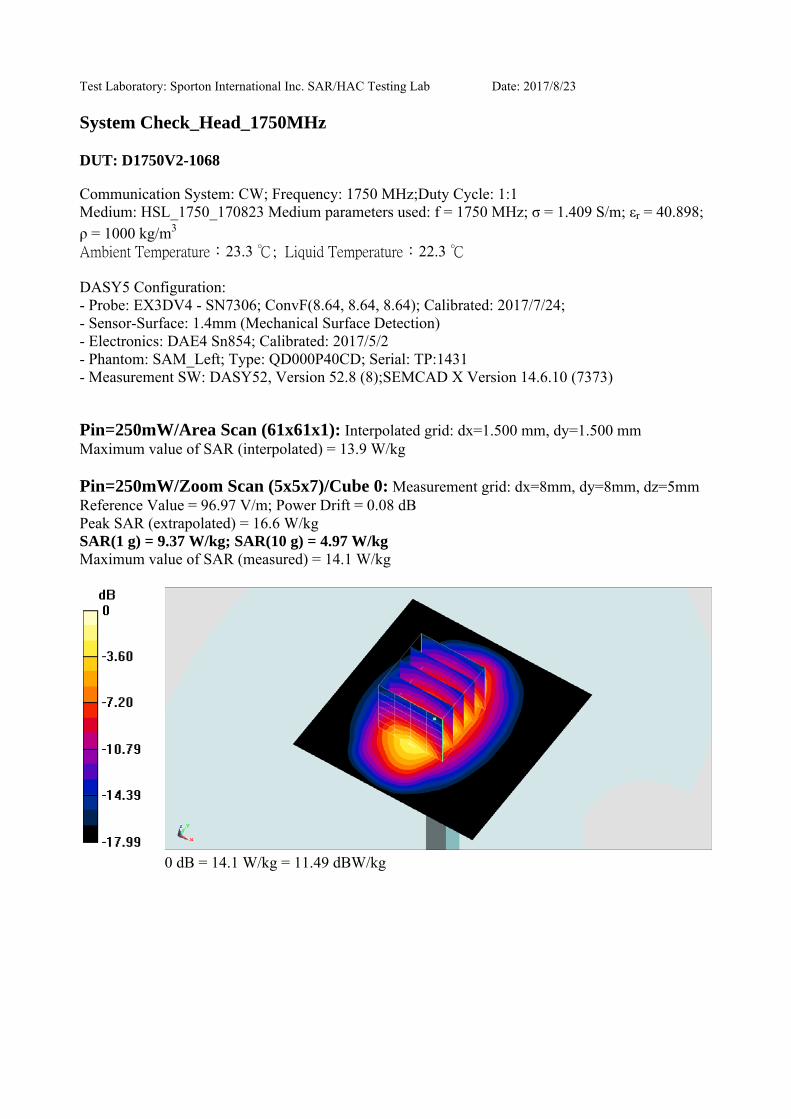
Test Laboratory: Sporton International Inc. SAR/HAC Testing Lab Date: 2017/8/23
System Check_Head_1750MHz
DUT: D1750V2-1068
Communication System: CW; Frequency: 1750 MHz;Duty Cycle: 1:1Medium: HSL_1750_170823 Medium parameters used: f = 1750 MHz; σ = 1.409 S/m; εr = 40.898;
3ρ = 1000 kg/m23.3 22.3
DASY5 Configuration:- Probe: EX3DV4 - SN7306; ConvF(8.64, 8.64, 8.64); Calibrated: 2017/7/24;- Sensor-Surface: 1.4mm (Mechanical Surface Detection)- Electronics: DAE4 Sn854; Calibrated: 2017/5/2- Phantom: SAM_Left; Type: QD000P40CD; Serial: TP:1431- Measurement SW: DASY52, Version 52.8 (8);SEMCAD X Version 14.6.10 (7373)
Pin=250mW/Area Scan (61x61x1): Interpolated grid: dx=1.500 mm, dy=1.500 mm Maximum value of SAR (interpolated) = 13.9 W/kg
Pin=250mW/Zoom Scan (5x5x7)/Cube 0: Measurement grid: dx=8mm, dy=8mm, dz=5mm Reference Value = 96.97 V/m; Power Drift = 0.08 dBPeak SAR (extrapolated) = 16.6 W/kgSAR(1 g) = 9.37 W/kg; SAR(10 g) = 4.97 W/kgMaximum value of SAR (measured) = 14.1 W/kg
0 dB = 14.1 W/kg = 11.49 dBW/kg
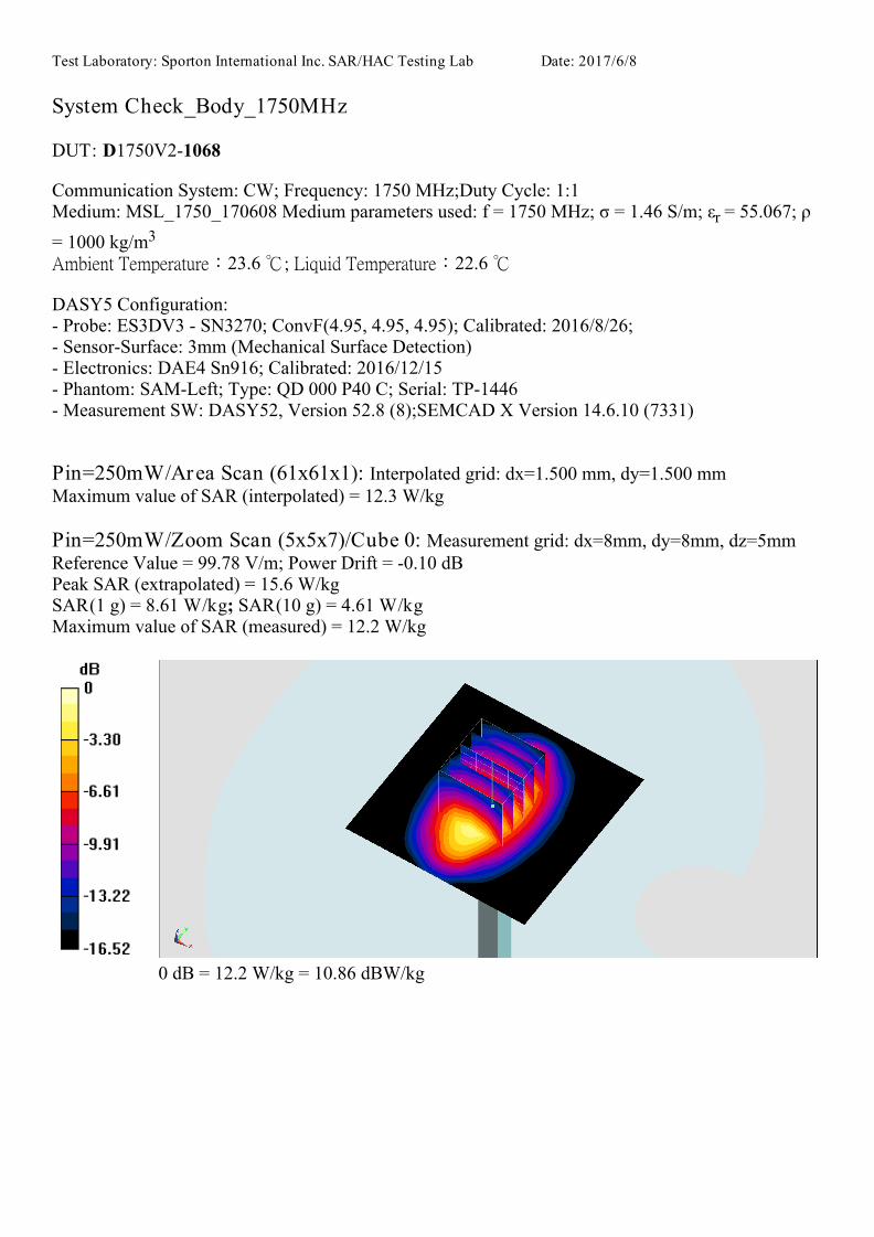
Test Laboratory: Sporton International Inc. SAR/HAC Testing Lab Date: 2017/6/8
System Check_Body_1750MHz
DUT: D1750V2-1068
Communication System: CW; Frequency: 1750 MHz;Duty Cycle: 1:1 Medium: MSL_1750_170608 Medium parameters used: f = 1750 MHz; σ = 1.46 S/m; εr = 55.067; ρ
= 1000 kg/m3 Ambient Temperature:23.6 ; Liquid Temperature:22.6
DASY5 Configuration:- Probe: ES3DV3 SN3270; ConvF(4.95, 4.95, 4.95); Calibrated: 2016/8/26; - Sensor-Surface: 3mm (Mechanical Surface Detection)- Electronics: DAE4 Sn916; Calibrated: 2016/12/15 - Phantom: SAM-Left; Type: QD 000 P40 C; Serial: TP-1446 - Measurement SW: DASY52, Version 52.8 (8);SEMCAD X Version 14.6.10 (7331)
Pin=250mW/Area Scan (61x61x1): Interpolated grid: dx=1.500 mm, dy=1.500 mmMaximum value of SAR (interpolated) = 12.3 W/kg
Pin=250mW/Zoom Scan (5x5x7)/Cube 0: Measurement grid: dx=8mm, dy=8mm, dz=5mmReference Value = 99.78 V/m; Power Drift = -0.10 dBPeak SAR (extrapolated) = 15.6 W/kgSAR(1 g) = 8.61 W/kg; SAR(10 g) = 4.61 W/kgMaximum value of SAR (measured) = 12.2 W/kg
0 dB = 12.2 W/kg = 10.86 dBW/kg

Test Laboratory: Sporton International Inc. SAR/HAC Testing Lab Date: 2017/8/18
System Check_Body_1750MHz
DUT: D1750V21068
Communication System: CW; Frequency: 1750 MHz;Duty Cycle: 1:1Medium: MSL_1750_170818 Medium parameters used: f = 1750 MHz; σ = 1.473 S/m; εr = 55.484; ρ= 1000 kg/m3 Ambient Temperature:23.9 ; Liquid Temperature:22.9
DASY5 Configuration: Probe: ES3DV3 SN3169; ConvF(4.95, 4.95, 4.95); Calibrated: 2017/5/11; SensorSurface: 3mm (Mechanical Surface Detection) Electronics: DAE4 Sn1399; Calibrated: 2016/11/17 Phantom: SAMLeft; Type: QD 000 P40 C; Serial: TP1446 Measurement SW: DASY52, Version 52.8 (8);SEMCAD X Version 14.6.10 (7331)
Pin=250mW/Area Scan (61x61x1): Interpolated grid: dx=1.500 mm, dy=1.500 mmMaximum value of SAR (interpolated) = 12.4 W/kg
Pin=250mW/Zoom Scan (5x5x7)/Cube 0: Measurement grid: dx=8mm, dy=8mm, dz=5mmReference Value = 90.31 V/m; Power Drift = 0.08 dBPeak SAR (extrapolated) = 16.0 W/kgSAR(1 g) = 9.44 W/kg; SAR(10 g) = 5.17 W/kgMaximum value of SAR (measured) = 11.5 W/kg
0 dB = 11.5 W/kg = 10.61 dBW/kg

Test Laboratory: Sporton International Inc. SAR/HAC Testing Lab Date: 2017/6/7
System Check_Head_1900MHz
DUT: D1900V2-5d041
Communication System: CW; Frequency: 1900 MHz;Duty Cycle: 1:1 Medium: HSL_1900_170607 Medium parameters used: f = 1900 MHz; σ = 1.424 S/m; εr = 40.526; ρ
= 1000 kg/m3 Ambient Temperature:23.2 ; Liquid Temperature:22.2
DASY5 Configuration:- Probe: ES3DV3 SN3270; ConvF(5.08, 5.08, 5.08); Calibrated: 2016/8/26; - Sensor-Surface: 3mm (Mechanical Surface Detection)- Electronics: DAE4 Sn916; Calibrated: 2016/12/15 - Phantom: SAM_Right; Type: QD000P40CD; Serial: 1884 - Measurement SW: DASY52, Version 52.8 (8);SEMCAD X Version 14.6.10 (7331)
Pin=250mW/Area Scan (61x61x1): Interpolated grid: dx=1.500 mm, dy=1.500 mmMaximum value of SAR (interpolated) = 13.7 W/kg
Pin=250mW/Zoom Scan (5x5x7)/Cube 0: Measurement grid: dx=8mm, dy=8mm, dz=5mmReference Value = 100.4 V/m; Power Drift = 0.04 dBPeak SAR (extrapolated) = 18.6 W/kgSAR(1 g) = 10.4 W/kg; SAR(10 g) = 5.47 W/kgMaximum value of SAR (measured) = 13.0 W/kg
0 dB = 13.0 W/kg = 11.14 dBW/kg

Test Laboratory: Sporton International Inc. SAR/HAC Testing Lab Date: 2017/6/12
System Check_Head_1900MHz
DUT: D1900V2-5d041
Communication System: CW; Frequency: 1900 MHz;Duty Cycle: 1:1
Medium: HSL_1900_170612 Medium parameters used: f = 1900 MHz; σ = 1.45 S/m; εr = 41.676; ρ
= 1000 kg/m3
23.2 22.2
DASY5 Configuration:
- Probe: ES3DV3 - SN3169; ConvF(5.03, 5.03, 5.03); Calibrated: 2017/5/11;
- Sensor-Surface: 3mm (Mechanical Surface Detection)
- Electronics: DAE4 Sn1399; Calibrated: 2016/11/17
- Phantom: SAM_Left; Type: QD000P40CD; Serial: TP:1431
- Measurement SW: DASY52, Version 52.8 (8);SEMCAD X Version 14.6.10 (7373)
Pin=250mW/Area Scan (61x61x1): Interpolated grid: dx=1.500 mm, dy=1.500 mm
Maximum value of SAR (interpolated) = 13.1 W/kg
Pin=250mW/Zoom Scan (5x5x7)/Cube 0: Measurement grid: dx=8mm, dy=8mm, dz=5mm
Reference Value = 96.48 V/m; Power Drift = -0.02 dB
Peak SAR (extrapolated) = 17.9 W/kg
SAR(1 g) = 10 W/kg; SAR(10 g) = 5.33 W/kg
Maximum value of SAR (measured) = 12.3 W/kg
0 dB = 12.3 W/kg = 10.90 dBW/kg

Test Laboratory: Sporton International Inc. SAR/HAC Testing Lab Date: 2017/8/23
System Check_Head_1900MHz
DUT: D1900V25d041
Communication System: CW; Frequency: 1900 MHz;Duty Cycle: 1:1Medium: HSL_1900_170823 Medium parameters used: f = 1900 MHz; σ = 1.405 S/m; εr = 40.394; ρ= 1000 kg/m3 Ambient Temperature:23.6 ; Liquid Temperature:22.6
DASY5 Configuration: Probe: ES3DV3 SN3169; ConvF(5.03, 5.03, 5.03); Calibrated: 2017/5/11; SensorSurface: 3mm (Mechanical Surface Detection) Electronics: DAE4 Sn1399; Calibrated: 2016/11/17 Phantom: SAM_Right; Type: QD000P40CD; Serial: 1884 Measurement SW: DASY52, Version 52.8 (8);SEMCAD X Version 14.6.10 (7331)
Pin=250mW/Area Scan (61x61x1): Interpolated grid: dx=1.500 mm, dy=1.500 mmMaximum value of SAR (interpolated) = 12.7 W/kg
Pin=250mW/Zoom Scan (5x5x7)/Cube 0: Measurement grid: dx=8mm, dy=8mm, dz=5mmReference Value = 96.48 V/m; Power Drift = 0.02 dBPeak SAR (extrapolated) = 17.3 W/kgSAR(1 g) = 9.72 W/kg; SAR(10 g) = 5.17 W/kgMaximum value of SAR (measured) = 11.9 W/kg
0 dB = 11.9 W/kg = 10.76 dBW/kg

Test Laboratory: Sporton International Inc. SAR/HAC Testing Lab Date: 2017/6/8
System Check_Body_1900MHz
DUT: D1900V2-5d041
Communication System: CW; Frequency: 1900 MHz;Duty Cycle: 1:1Medium: MSL_1900_170608 Medium parameters used: f = 1900 MHz; σ = 1.521 S/m; εr = 55.414; ρ= 1000 kg/m3 Ambient Temperature:23.6 ; Liquid Temperature:22.6
DASY5 Configuration:- Probe: ES3DV3 - SN3270; ConvF(4.7, 4.7, 4.7); Calibrated: 2016/8/26; - Sensor-Surface: 3mm (Mechanical Surface Detection)- Electronics: DAE4 Sn916; Calibrated: 2016/12/15- Phantom: SAM-Left; Type: QD 000 P40 C; Serial: TP-1446- Measurement SW: DASY52, Version 52.8 (8);SEMCAD X Version 14.6.10 (7331)
Pin=250mW/Area Scan (61x61x1): Interpolated grid: dx=1.500 mm, dy=1.500 mmMaximum value of SAR (interpolated) = 13.2 W/kg
Pin=250mW/Zoom Scan (5x5x7)/Cube 0: Measurement grid: dx=8mm, dy=8mm, dz=5mmReference Value = 91.95 V/m; Power Drift = -0.00 dBPeak SAR (extrapolated) = 17.2 W/kgSAR(1 g) = 10.1 W/kg; SAR(10 g) = 5.37 W/kgMaximum value of SAR (measured) = 12.2 W/kg
0 dB = 12.2 W/kg = 10.86 dBW/kg

Test Laboratory: Sporton International Inc. SAR/HAC Testing Lab Date: 2017/8/17
System Check_Body_1900MHz
DUT: D1900V25d041
Communication System: CW; Frequency: 1900 MHz;Duty Cycle: 1:1Medium: MSL_1900_170817 Medium parameters used: f = 1900 MHz; σ = 1.573 S/m; εr = 54.426; ρ= 1000 kg/m3 Ambient Temperature:23.9 ; Liquid Temperature:22.9
DASY5 Configuration: Probe: ES3DV3 SN3169; ConvF(4.72, 4.72, 4.72); Calibrated: 2017/5/11; SensorSurface: 3mm (Mechanical Surface Detection) Electronics: DAE4 Sn1399; Calibrated: 2016/11/17 Phantom: SAMLeft; Type: QD 000 P40 C; Serial: TP1446 Measurement SW: DASY52, Version 52.8 (8);SEMCAD X Version 14.6.10 (7331)
Pin=250mW/Area Scan (61x61x1): Interpolated grid: dx=1.500 mm, dy=1.500 mmMaximum value of SAR (interpolated) = 13.5 W/kg
Pin=250mW/Zoom Scan (5x5x7)/Cube 0: Measurement grid: dx=8mm, dy=8mm, dz=5mmReference Value = 87.77 V/m; Power Drift = 0.02 dBPeak SAR (extrapolated) = 17.7 W/kgSAR(1 g) = 10 W/kg; SAR(10 g) = 5.27 W/kgMaximum value of SAR (measured) = 12.3 W/kg
0 dB = 12.3 W/kg = 10.90 dBW/kg
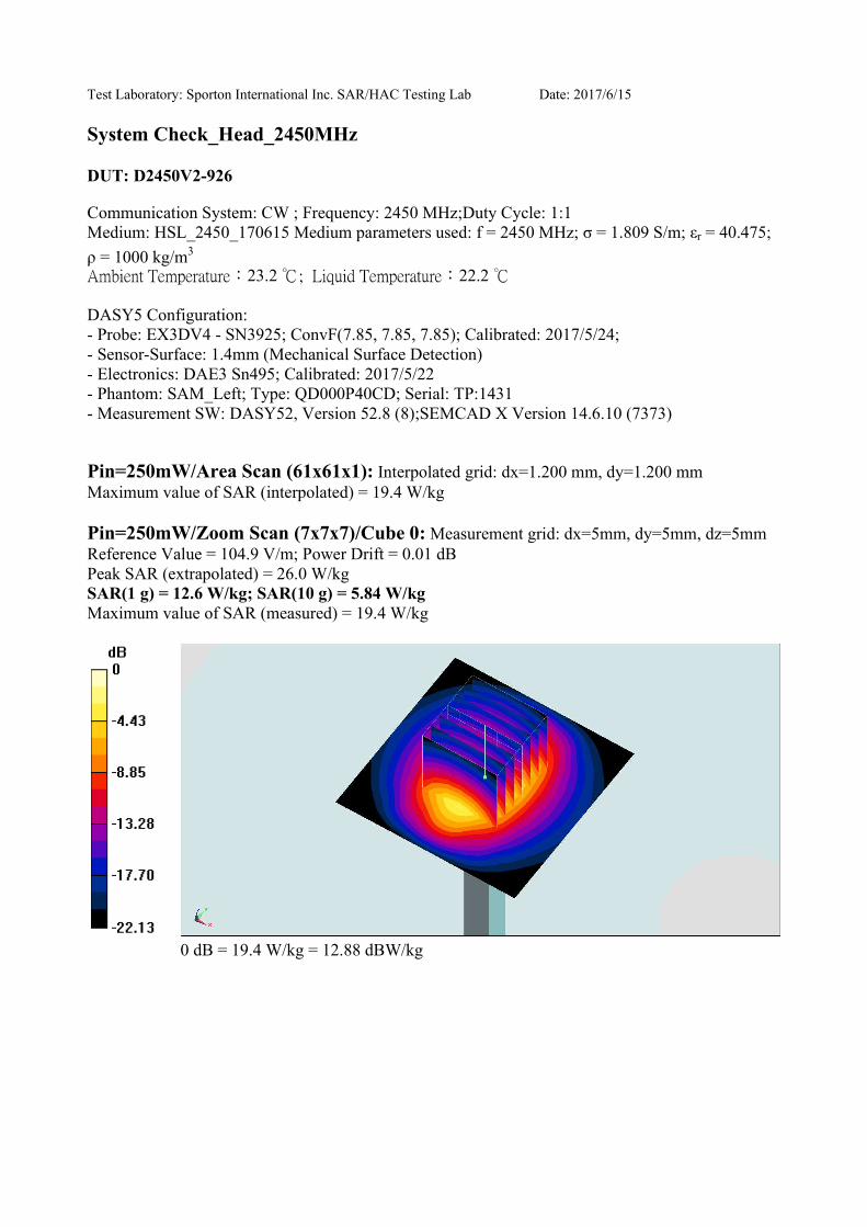
Test Laboratory: Sporton International Inc. SAR/HAC Testing Lab Date: 2017/6/15
System Check_Head_2450MHz
DUT: D2450V2-926
Communication System: CW ; Frequency: 2450 MHz;Duty Cycle: 1:1
Medium: HSL_2450_170615 Medium parameters used: f = 2450 MHz; σ = 1.809 S/m; εr = 40.475;
ρ = 1000 kg/m3
23.2 22.2
DASY5 Configuration:
- Probe: EX3DV4 - SN3925; ConvF(7.85, 7.85, 7.85); Calibrated: 2017/5/24;
- Sensor-Surface: 1.4mm (Mechanical Surface Detection)
- Electronics: DAE3 Sn495; Calibrated: 2017/5/22
- Phantom: SAM_Left; Type: QD000P40CD; Serial: TP:1431
- Measurement SW: DASY52, Version 52.8 (8);SEMCAD X Version 14.6.10 (7373)
Pin=250mW/Area Scan (61x61x1): Interpolated grid: dx=1.200 mm, dy=1.200 mm
Maximum value of SAR (interpolated) = 19.4 W/kg
Pin=250mW/Zoom Scan (7x7x7)/Cube 0: Measurement grid: dx=5mm, dy=5mm, dz=5mm
Reference Value = 104.9 V/m; Power Drift = 0.01 dB
Peak SAR (extrapolated) = 26.0 W/kg
SAR(1 g) = 12.6 W/kg; SAR(10 g) = 5.84 W/kg
Maximum value of SAR (measured) = 19.4 W/kg
0 dB = 19.4 W/kg = 12.88 dBW/kg

Test Laboratory: Sporton International Inc. SAR/HAC Testing Lab Date: 2017/6/16
System Check_Head_2450MHz
DUT: D2450V2-926
Communication System: CW ; Frequency: 2450 MHz;Duty Cycle: 1:1
Medium: HSL_2450_170616 Medium parameters used: f = 2450 MHz; σ = 1.845 S/m; εr = 40.648;
ρ = 1000 kg/m3
23.4 22.4
DASY5 Configuration:
- Probe: EX3DV4 - SN3925; ConvF(7.85, 7.85, 7.85); Calibrated: 2017/5/24;
- Sensor-Surface: 1.4mm (Mechanical Surface Detection)
- Electronics: DAE3 Sn495; Calibrated: 2017/5/22
- Phantom: SAM-Right; Type: SAM; Serial: TP-1503
- Measurement SW: DASY52, Version 52.8 (8);SEMCAD X Version 14.6.10 (7373)
Pin=250mW/Area Scan (61x61x1): Interpolated grid: dx=1.200 mm, dy=1.200 mm
Maximum value of SAR (interpolated) = 22.4 W/kg
Pin=250mW/Zoom Scan (7x7x7)/Cube 0: Measurement grid: dx=5mm, dy=5mm, dz=5mm
Reference Value = 105.6 V/m; Power Drift = 0.01 dB
Peak SAR (extrapolated) = 29.1 W/kg
SAR(1 g) = 13.4 W/kg; SAR(10 g) = 6.19 W/kg
Maximum value of SAR (measured) = 20.6 W/kg
0 dB = 20.6 W/kg = 13.14 dBW/kg
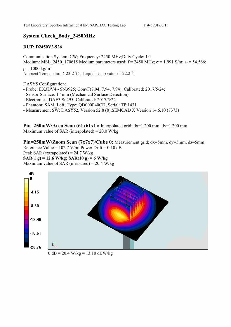
Test Laboratory: Sporton International Inc. SAR/HAC Testing Lab Date: 2017/6/15
System Check_Body_2450MHz
DUT: D2450V2-926
Communication System: CW; Frequency: 2450 MHz;Duty Cycle: 1:1
Medium: MSL_2450_170615 Medium parameters used: f = 2450 MHz; σ = 1.991 S/m; εr = 54.566;
ρ = 1000 kg/m3
23.2 22.2
DASY5 Configuration:
- Probe: EX3DV4 - SN3925; ConvF(7.94, 7.94, 7.94); Calibrated: 2017/5/24;
- Sensor-Surface: 1.4mm (Mechanical Surface Detection)
- Electronics: DAE3 Sn495; Calibrated: 2017/5/22
- Phantom: SAM_Left; Type: QD000P40CD; Serial: TP:1431
- Measurement SW: DASY52, Version 52.8 (8);SEMCAD X Version 14.6.10 (7373)
Pin=250mW/Area Scan (61x61x1): Interpolated grid: dx=1.200 mm, dy=1.200 mm
Maximum value of SAR (interpolated) = 20.0 W/kg
Pin=250mW/Zoom Scan (7x7x7)/Cube 0: Measurement grid: dx=5mm, dy=5mm, dz=5mm
Reference Value = 102.7 V/m; Power Drift = 0.10 dB
Peak SAR (extrapolated) = 24.7 W/kg
SAR(1 g) = 12.6 W/kg; SAR(10 g) = 6 W/kg
Maximum value of SAR (measured) = 20.4 W/kg
0 dB = 20.4 W/kg = 13.10 dBW/kg

Test Laboratory: Sporton International Inc. SAR/HAC Testing Lab Date: 2017/6/7
System Check_Head_2600MHz
DUT: D2600V21008
Communication System: CW; Frequency: 2600 MHz;Duty Cycle: 1:1Medium: HSL_2600_170607 Medium parameters used: f = 2600 MHz; σ = 2.012 S/m; εr = 37.953; ρ= 1000 kg/m3 Ambient Temperature:23.2 ; Liquid Temperature:22.2
DASY5 Configuration: Probe: ES3DV3 SN3270; ConvF(4.37, 4.37, 4.37); Calibrated: 2016/8/26; SensorSurface: 3mm (Mechanical Surface Detection) Electronics: DAE4 Sn778; Calibrated: 2017/5/22 Phantom: SAM_Right; Type: QD000P40CD; Serial: 1884 Measurement SW: DASY52, Version 52.8 (8);SEMCAD X Version 14.6.10 (7331)
Pin=250mW/Area Scan (81x81x1): Interpolated grid: dx=1.200 mm, dy=1.200 mmMaximum value of SAR (interpolated) = 22.7 W/kg
Pin=250mW/Zoom Scan (7x7x7)/Cube 0: Measurement grid: dx=5mm, dy=5mm, dz=5mmReference Value = 113.9 V/m; Power Drift = 0.15 dBPeak SAR (extrapolated) = 31.5 W/kgSAR(1 g) = 14.5 W/kg; SAR(10 g) = 6.48 W/kgMaximum value of SAR (measured) = 22.8 W/kg
0 dB = 22.8 W/kg = 13.58 dBW/kg
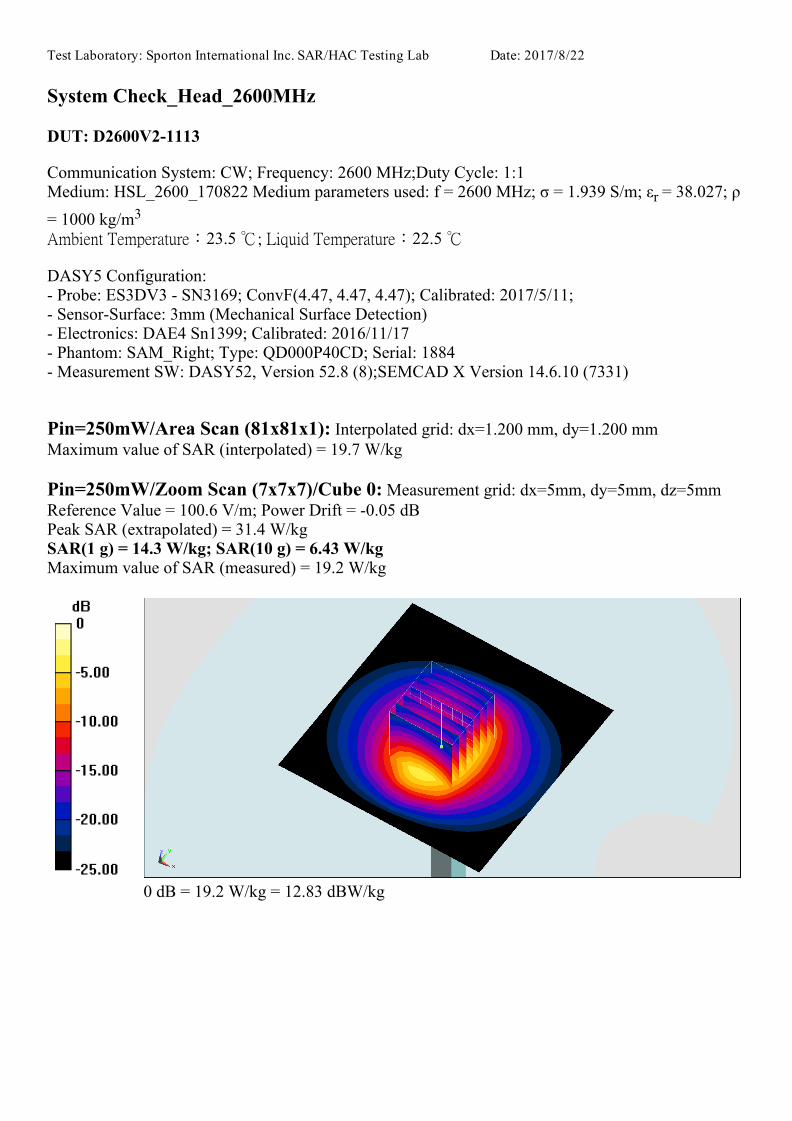
Test Laboratory: Sporton International Inc. SAR/HAC Testing Lab Date: 2017/8/22
System Check_Head_2600MHz
DUT: D2600V21113
Communication System: CW; Frequency: 2600 MHz;Duty Cycle: 1:1Medium: HSL_2600_170822 Medium parameters used: f = 2600 MHz; σ = 1.939 S/m; εr = 38.027; ρ= 1000 kg/m3 Ambient Temperature:23.5 ; Liquid Temperature:22.5
DASY5 Configuration: Probe: ES3DV3 SN3169; ConvF(4.47, 4.47, 4.47); Calibrated: 2017/5/11; SensorSurface: 3mm (Mechanical Surface Detection) Electronics: DAE4 Sn1399; Calibrated: 2016/11/17 Phantom: SAM_Right; Type: QD000P40CD; Serial: 1884 Measurement SW: DASY52, Version 52.8 (8);SEMCAD X Version 14.6.10 (7331)
Pin=250mW/Area Scan (81x81x1): Interpolated grid: dx=1.200 mm, dy=1.200 mmMaximum value of SAR (interpolated) = 19.7 W/kg
Pin=250mW/Zoom Scan (7x7x7)/Cube 0: Measurement grid: dx=5mm, dy=5mm, dz=5mmReference Value = 100.6 V/m; Power Drift = 0.05 dBPeak SAR (extrapolated) = 31.4 W/kgSAR(1 g) = 14.3 W/kg; SAR(10 g) = 6.43 W/kgMaximum value of SAR (measured) = 19.2 W/kg
0 dB = 19.2 W/kg = 12.83 dBW/kg

Test Laboratory: Sporton International Inc. SAR/HAC Testing Lab Date: 2017/6/9
System Check_Body_2600MHz
DUT: D2600V2-1008
Communication System: CW; Frequency: 2600 MHz;Duty Cycle: 1:1Medium: MSL_2600_170609 Medium parameters used: f = 2600 MHz; σ = 2.162 S/m; εr = 52.714; ρ= 1000 kg/m3 Ambient Temperature:23.5 ; Liquid Temperature:22.5
DASY5 Configuration:- Probe: ES3DV3 - SN3270; ConvF(4.12, 4.12, 4.12); Calibrated: 2016/8/26; - Sensor-Surface: 3mm (Mechanical Surface Detection)- Electronics: DAE4 Sn778; Calibrated: 2017/5/22- Phantom: SAM_Right; Type: QD000P40CD; Serial: 1884- Measurement SW: DASY52, Version 52.8 (8);SEMCAD X Version 14.6.10 (7331)
Pin=250mW/Area Scan (71x71x1): Interpolated grid: dx=1.200 mm, dy=1.200 mmMaximum value of SAR (interpolated) = 19.9 W/kg
Pin=250mW/Zoom Scan (7x7x7)/Cube 0: Measurement grid: dx=5mm, dy=5mm, dz=5mmReference Value = 97.52 V/m; Power Drift = -0.05 dBPeak SAR (extrapolated) = 30.2 W/kgSAR(1 g) = 14.3 W/kg; SAR(10 g) = 6.39 W/kgMaximum value of SAR (measured) = 19.1 W/kg
0 dB = 19.1 W/kg = 12.81 dBW/kg

Test Laboratory: Sporton International Inc. SAR/HAC Testing Lab Date: 2017/8/18
System Check_Body_2600MHz
DUT: D2600V21113
Communication System: CW; Frequency: 2600 MHz;Duty Cycle: 1:1Medium: MSL_2600_170818 Medium parameters used: f = 2600 MHz; σ = 2.183 S/m; εr = 54.42; ρ= 1000 kg/m3 Ambient Temperature:23.9 ; Liquid Temperature:22.9
DASY5 Configuration: Probe: ES3DV3 SN3169; ConvF(4.17, 4.17, 4.17); Calibrated: 2017/5/11; SensorSurface: 3mm (Mechanical Surface Detection) Electronics: DAE4 Sn1399; Calibrated: 2016/11/17 Phantom: SAM_Right; Type: QD000P40CD; Serial: 1884 Measurement SW: DASY52, Version 52.8 (8);SEMCAD X Version 14.6.10 (7331)
Pin=250mW/Area Scan (61x61x1): Interpolated grid: dx=1.200 mm, dy=1.200 mmMaximum value of SAR (interpolated) = 19.6 W/kg
Pin=250mW/Zoom Scan (7x7x7)/Cube 0: Measurement grid: dx=5mm, dy=5mm, dz=5mmReference Value = 92.76 V/m; Power Drift = 0.06 dBPeak SAR (extrapolated) = 28.3 W/kgSAR(1 g) = 13.8 W/kg; SAR(10 g) = 6.2 W/kgMaximum value of SAR (measured) = 18.1 W/kg
0 dB = 18.1 W/kg = 12.58 dBW/kg
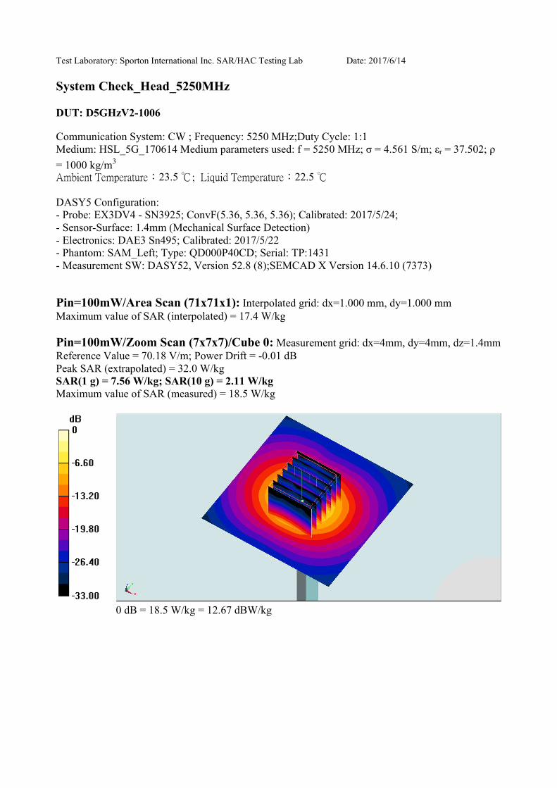
Test Laboratory: Sporton International Inc. SAR/HAC Testing Lab Date: 2017/6/14
System Check_Head_5250MHz
DUT: D5GHzV2-1006
Communication System: CW ; Frequency: 5250 MHz;Duty Cycle: 1:1
Medium: HSL_5G_170614 Medium parameters used: f = 5250 MHz; σ = 4.561 S/m; εr = 37.502; ρ
= 1000 kg/m3
23.5 22.5
DASY5 Configuration:
- Probe: EX3DV4 - SN3925; ConvF(5.36, 5.36, 5.36); Calibrated: 2017/5/24;
- Sensor-Surface: 1.4mm (Mechanical Surface Detection)
- Electronics: DAE3 Sn495; Calibrated: 2017/5/22
- Phantom: SAM_Left; Type: QD000P40CD; Serial: TP:1431
- Measurement SW: DASY52, Version 52.8 (8);SEMCAD X Version 14.6.10 (7373)
Pin=100mW/Area Scan (71x71x1): Interpolated grid: dx=1.000 mm, dy=1.000 mm
Maximum value of SAR (interpolated) = 17.4 W/kg
Pin=100mW/Zoom Scan (7x7x7)/Cube 0: Measurement grid: dx=4mm, dy=4mm, dz=1.4mm
Reference Value = 70.18 V/m; Power Drift = -0.01 dB
Peak SAR (extrapolated) = 32.0 W/kg
SAR(1 g) = 7.56 W/kg; SAR(10 g) = 2.11 W/kg
Maximum value of SAR (measured) = 18.5 W/kg
0 dB = 18.5 W/kg = 12.67 dBW/kg
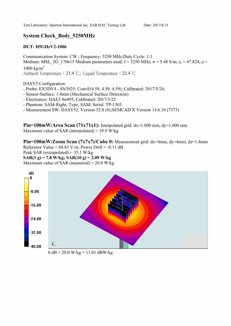
Test Laboratory: Sporton International Inc. SAR/HAC Testing Lab Date: 2017/6/15
System Check_Body_5250MHz
DUT: D5GHzV2-1006
Communication System: CW ; Frequency: 5250 MHz;Duty Cycle: 1:1
Medium: MSL_5G_170615 Medium parameters used: f = 5250 MHz; σ = 5.48 S/m; εr = 47.824; ρ =
1000 kg/m3
23.4 22.4
DASY5 Configuration:
- Probe: EX3DV4 - SN3925; ConvF(4.59, 4.59, 4.59); Calibrated: 2017/5/24;
- Sensor-Surface: 1.4mm (Mechanical Surface Detection)
- Electronics: DAE3 Sn495; Calibrated: 2017/5/22
- Phantom: SAM-Right; Type: SAM; Serial: TP-1303
- Measurement SW: DASY52, Version 52.8 (8);SEMCAD X Version 14.6.10 (7373)
Pin=100mW/Area Scan (71x71x1): Interpolated grid: dx=1.000 mm, dy=1.000 mm
Maximum value of SAR (interpolated) = 19.9 W/kg
Pin=100mW/Zoom Scan (7x7x7)/Cube 0: Measurement grid: dx=4mm, dy=4mm, dz=1.4mm
Reference Value = 68.83 V/m; Power Drift = -0.11 dB
Peak SAR (extrapolated) = 35.1 W/kg
SAR(1 g) = 7.8 W/kg; SAR(10 g) = 2.09 W/kg
Maximum value of SAR (measured) = 20.0 W/kg
0 dB = 20.0 W/kg = 13.01 dBW/kg

Test Laboratory: Sporton International Inc. SAR/HAC Testing Lab Date: 2017/6/14
System Check_Head_5600MHz
DUT: D5GHzV2-1006
Communication System: CW ; Frequency: 5600 MHz;Duty Cycle: 1:1
Medium: HSL_5G_170614 Medium parameters used: f = 5600 MHz; σ = 4.89 S/m; εr = 36.976; ρ =
1000 kg/m3
23.5 22.5
DASY5 Configuration:
- Probe: EX3DV4 - SN3925; ConvF(4.72, 4.72, 4.72); Calibrated: 2017/5/24;
- Sensor-Surface: 1.4mm (Mechanical Surface Detection)
- Electronics: DAE3 Sn495; Calibrated: 2017/5/22
- Phantom: SAM_Left; Type: QD000P40CD; Serial: TP:1431
- Measurement SW: DASY52, Version 52.8 (8);SEMCAD X Version 14.6.10 (7373)
Pin=100mW/Area Scan (71x71x1): Interpolated grid: dx=1.000 mm, dy=1.000 mm
Maximum value of SAR (interpolated) = 20.9 W/kg
Pin=100mW/Zoom Scan (7x7x7)/Cube 0: Measurement grid: dx=4mm, dy=4mm, dz=1.4mm
Reference Value = 70.82 V/m; Power Drift = 0.14 dB
Peak SAR (extrapolated) = 36.7 W/kg
SAR(1 g) = 8.45 W/kg; SAR(10 g) = 2.31 W/kg
Maximum value of SAR (measured) = 21.7 W/kg
0 dB = 21.7 W/kg = 13.36 dBW/kg

Test Laboratory: Sporton International Inc. SAR/HAC Testing Lab Date: 2017/6/15
System Check_Body_5600MHz
DUT: D5GHzV2-1006
Communication System: CW ; Frequency: 5600 MHz;Duty Cycle: 1:1
Medium: MSL_5G_170615 Medium parameters used: f = 5600 MHz; σ = 5.955 S/m; εr = 47.205; ρ
= 1000 kg/m3
23.4 22.4
DASY5 Configuration:
- Probe: EX3DV4 - SN3925; ConvF(4.17, 4.17, 4.17); Calibrated: 2017/5/24;
- Sensor-Surface: 1.4mm (Mechanical Surface Detection)
- Electronics: DAE3 Sn495; Calibrated: 2017/5/22
- Phantom: SAM-Right; Type: SAM; Serial: TP-1303
- Measurement SW: DASY52, Version 52.8 (8);SEMCAD X Version 14.6.10 (7373)
Pin=100mW/Area Scan (71x71x1): Interpolated grid: dx=1.000 mm, dy=1.000 mm
Maximum value of SAR (interpolated) = 20.9 W/kg
Pin=100mW/Zoom Scan (7x7x7)/Cube 0: Measurement grid: dx=4mm, dy=4mm, dz=1.4mm
Reference Value = 68.22 V/m; Power Drift = 0.13 dB
Peak SAR (extrapolated) = 37.4 W/kg
SAR(1 g) = 8.17 W/kg; SAR(10 g) = 2.21 W/kg
Maximum value of SAR (measured) = 20.8 W/kg
0 dB = 20.8 W/kg = 13.18 dBW/kg