fatigue mechanisms in p/m components · fatigue mechanisms in p/m components ... and fe-2cu-0.8c...
TRANSCRIPT

FATIGUE MECHANISMS IN P/M COMPONENTS
Worcester Polytechnic InstituteApril 28-29, 2004
Diana Lados & Diran Apelian
Morris Boorky Powder Metallurgy Research Center

OUTLINE
I. Impact of Porosity on Fatigue and Fatigue Crack Growth Behavior of P/M Components (examples from the literature)
Relevance of open/closed porosity
Open/closed porosity measurement techniques
II. WPI project … Objectives and Experimental Plan

BACKGROUNDFactors controlling fatigue behavior …
1. Porosity/density:
Amount (% Porosity)Type (Open/Closed)Morphology (size/shape - due to initial powder
morphology and sintering conditions)Distribution (initial powder size)
2. Microstructural phases:
Amount (% Phase)Type (Martensite, Bainite, Pearlite, Ferrite,
+ Cementite, Ni-rich areas, etc.)Size (Fine/Coarse)

BACKGROUNDFatigue life vs. density/porosity …
Fatigue limit Porosity %
for both: P/M ironP/M steels
in: as-sinteredheat treated (quench and tempered)

BACKGROUNDFatigue life vs. density/porosity … sintered P/M iron
Water atomized
Reduced sponge
4 hrs @ 2050°F
30 min @ 2280°F
Sintering treatment affects fatigue life at intermediate porosity ranges
(water atomized iron powder, single or double pressed, and sintered @ 2050°F (30 min) and 2280°F (4 hrs))
Life (samples from reduced sponge powder) >Life (samples from water atomized powder)
(single, double, triple sequence sintering @ 2050°F or 2200°F)

BACKGROUNDFatigue life vs. density/porosity … sintered P/M steels
Large
Small
Base
Bimodal
20 min @
2050°F
30 min @
2340°F
ABC (atomized)
MH (sponge)Fe-1.5Cu-1.75Ni-0.5Mo-0.5C (SE)
Fe-1.5Cu-4Ni-0.5Mo-0.5C (AE)and Fe-2Cu-0.8C (30 min @ 2050°F)

BACKGROUNDFatigue life vs. density/porosity … sintered P/M steels
Fe-2Cu-2.5Ni (60 min @ 2280°F)Fe-1.5Cu-0.6C (30 min @ 2050°F)

BACKGROUNDFatigue life vs. density/porosity … Q&T - P/M steels
S Q&T
Fe-1.5Cu-1.75Ni-0.5Mo-0.6C
Fe-1.5Cu-1.75Ni-0.5Mo-0.5C (sponge)
Fe-1.5Cu-1.75Ni-0.5Mo-0.5C (atomized)
Fe-1.5Cu-4Ni-0.5Mo-0.5C (atomized)

BACKGROUND∆Kth vs. density/porosity … sintered P/M iron and steels
Fe (atomized)
S Q&T
Fe-1.5Cu-1.75Ni-0.5Mo-0.5C (sponge)
Fe-1.5Cu-1.75Ni-0.5Mo-0.5C (atomized)
Fe-1.5Cu-4Ni-0.5Mo-0.5C (atomized)Fe-1.5Cu-1.75Ni-0.5Mo-0.6C Fe-1.75Ni-0.5Mo-0.5C (atomized)

BACKGROUNDFCGR and ∆KFT vs. density/porosity …
Fe-2Cu-2.5Ni (60 min @ 2280°F)Fe-1.5Cu-0.6C (30 min @ 2050°F)

BACKGROUND∆KFT vs. density/porosity …
Fe-Cu-Ni-Mo-C alloys
as-sintered Fe-0.8Cu-1.8Ni-0.5Mo-0.2Mn-0.4C

BACKGROUND∆KFT vs. density/porosity …
FL 4605
heat treatedas-sinteredFL = pre-alloyed
FLN = pre-alloyed + elemental Ni blend
FN = elemental blended

BACKGROUND∆KFT vs. density/porosity …
Homogeneous
Inhomogeneous
Fe-1.75Ni-0.5Mo-0.5C
as-sintered

BACKGROUNDTotal porosity vs. Open/Closed porosity …
Open porosity
Isolated porosity
Closed porosity
Total Porosity: Open + Closed + Isolated
Open porosity: continuous pore channels intersecting the surface of the specimen (and each other)
Closed porosity: closed gaps between powder particles resulting from compaction and/or sintering (not accessible to the surface BUT can be connected to each other !!)
Isolated porosity: pores present in the initial powder particles (not affected by compaction and sintering)

BACKGROUNDOpen porosity … the controlling parameter ?
P/M iron
Tension-
Plane bending
• Axial testing – volume properties
• Bending – surface properties
compression

BACKGROUNDOpen porosity … the controlling parameter ?
P/M iron
Region I: closed porosity (∆Kth ≈ ct.)
Region II: ∆Kth porosity
Region III: open porosity (∆Kth ≈ ct.and low)
Fe-1.75Ni-0.5Mo-0.5C
(no increase in threshold above ~7.5 g/cm3)
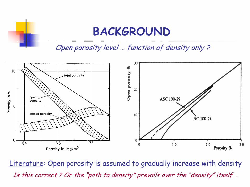
BACKGROUNDOpen porosity level … function of density only ?
Literature: Open porosity is assumed to gradually increase with densityIs this correct ? Or the “path to density” prevails over the “density” itself …

BACKGROUNDOpen porosity measurement techniques …
Open porosity penetrated by He
Isolated porosity
Closed porosity
Open porosity penetrated by oil
Open porosity unresolved by penetrating oil
Oil-impregnation (ASTM B328)
Gas-impregnation
More accurate measurements of open porosity due to increased pore penetration ability of gases compared to oils - RECOMMENDED
Calculate the interconnected porosity from the volume of oil that has impregnated the specimen

BACKGROUNDGas-impregnation measurement techniques … pycnometry
Gas displacement pycnometer: a sample of known weight (a solid, a powder, or a porous material) is placed in one of the chambers and the change in pressure needed to balance the two chambers is used to calculate the volume of the sample (P1V1=P2V2)
pore free density pycnometric density bulk density

BACKGROUNDCalculation of open/closed porosity using He pycnometry …
freepore
bulktotal 1V
−ρρ
−= % Total porosity = 100 x Vtotal
cpycnometri
bulkopen 1V
ρρ
−= % Open porosity = 100 x Vopen
Vclosed = Vtotal – Vopen % Closed porosity = 100 x Vclosed
* The amount of isolated porosity was assumed insignificantly small

BACKGROUNDOpen/closed porosity results … P/M iron
0
5
10
15
20
25
5.50 6.00 6.50 7.00 7.50 8.00
Density (g/cm3)
Poro
sity
(%)
Danninger et al. [18]Ledoux and Prioul [1]Lados and Apelian (pycnometry)Lados and Apelian (oil)
Total porosity
Open porosity
Closed porosity

BACKGROUNDOpen/closed porosity results using He pycnometry …
… P/M steels in sintered conditionsSintered conditions
0
0.25
0.5
0.75
1
1.25
6.8 6.9 7 7.1 7.2 7.3 7.4
Density (g/cm3)
Clo
sed
poro
sity
(%)
A4601A4001
A4601A4001

BACKGROUND
Quenched and tempered conditions
0
0.25
0.5
0.75
1
1.25
6.8 6.9 7 7.1 7.2 7.3 7.4
Density (g/cm3)
Clo
sed
poro
sity
(%)
A4601A4001
Open/closed porosity results using He pycnometry … … P/M steels in quenched and tempered conditions
A4601 after oil quench
A4001 after gas quench

BACKGROUNDOpen/closed porosity results using He pycnometry … … P/M steels in high temperature/long time sintering
Sintered conditions
0
1
2
3
4
5
6
7
6.8 6.9 7 7.1 7.2 7.3 7.4
Density (g/cm3)
Clo
sed
poro
sity
(%)
A4601 @ 2350°F for 6 hrs
A4601 @ 2050°F for 30 min (pycnometry)
oil pycnometry

BACKGROUNDSources of errors in evaluating open porosity …
1. Open porosity measurement technique:Higher closed porosity level is measured using oil-impregnation (the segments of open porosity channels that are not reached by oil are incorrectly assumed to be closed porosity);It is more accurate at high level of closed porosity;Pycnometric measurements are more accurate;
2. Correlating open/closed porosity to density alone: Simple correlations open porosity level – density are incorrect;The path followed to reach the density is critical for correct interpretations of open/closed porosity;No closed porosity is achieved through compaction and regular sintering T and t.

OBJECTIVES
Study the effects of density/porosity on the fatigue initiation and propagation in P/M components;
Investigate the porosity/microstructure interactions;
Understand the effects of different microstructural phases on dynamic properties – mechanisms;
Create guidelines for fatigue design corroborated with the fundamental understanding of the alloys behavior;
Optimize the material characteristics and processing parameters for enhanced fatigue response.

EXPERIMENTAL APPROACHMaterials selection …
Pre-alloyed
(QMP ATOMET 4601 Ni-Mo pre-alloyed powder)
Admixed
(QMP ATOMET 4001Mo pre-alloyed powder admixed with Ni)
0.60.15-0.180.50-0.551.75-1.8[%]
Sintered CMnMoNiChemical
composition
Graphite Ni
Graphite
Molding grades particles (70-85 µm)

EXPERIMENTAL APPROACHPhases …
Phase I (a):Phase I (a): Mechanistic understanding of the effects of pore amount on fatigue behavior;
Pore/Microstructure (matrix) interactions;
Phase I (b):Phase I (b): Microstructure effects on fatigue response;
Microstructure 1 vs. Microstructure 2;
Phase II:Phase II: Is fatigue resistance a state function ???
Effects of pore size/shape/type on fatigue.

EXPERIMENTAL APPROACHPhase I … Two microstructural considerations
Low High density density
Pore Pore/Matrix Matrix control control control
A.
??B.Cooling Fatigue rate 2 behavior 2
Cooling Fatigue rate 1 behavior 1 Microstructure 1
Microstructure 2

EXPERIMENTAL APPROACHPhase I … Density levels selection
Micro-structure
Set 37.8+
Set 27.2-7.3
Set 1~6.8
Density [g/cm3]
Produce samples of our composition in both pre-alloyed and admixed conditions;
Adjust compaction (conventional press, warm compaction, powder forging, etc.) to get the full range of densities:

EXPERIMENTAL APPROACH
Compaction:
low densities (Set 1): normal compaction;
↔ intermediate densities (Set 2): controlled temperature compaction (warm compaction 145°F );
high densities (Set 3): powder forging.
Sintering:
temperature:T=2050°F ;
time: t=30 min;T and t invariant for phase I.
Phase I … Compaction +Sintering

EXPERIMENTAL APPROACHPhase I … Heat treatment
Post sintering heat treatment:
austenitize @ 1700°F for 30 min (similar austenitic grains)
quench to 2 microstructures (for both pre-alloyed and admixed):
temper @ 400°F for 1 hr (similar matrix micro-hardness)
Martensite + R.A. +
(5%Ni reach areas)
35%Martensite + 60%Pearlite + R.A. + (~5%Ni reach areas)
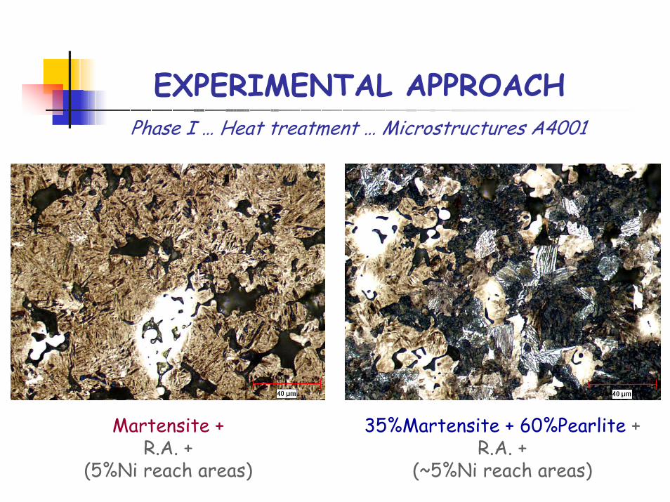
EXPERIMENTAL APPROACHPhase I … Heat treatment … Microstructures A4001
Martensite + R.A. +
(5%Ni reach areas)
35%Martensite + 60%Pearlite + R.A. +
(~5%Ni reach areas)
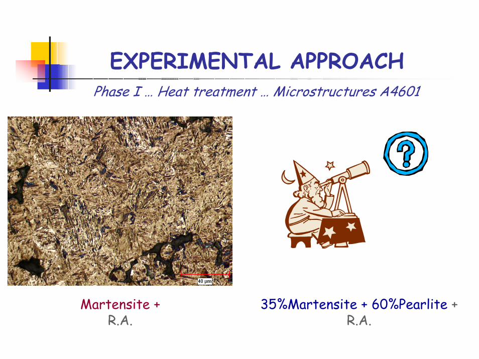
EXPERIMENTAL APPROACHPhase I … Heat treatment … Microstructures A4601
Martensite + R.A.
35%Martensite + 60%Pearlite + R.A.

EXPERIMENTAL APPROACHFatigue testing … Specimens and equipment
Dog-bone specimens for pull-pull/push-pull
CT specimens for FCGR
[Courtesy of Westmoreland]-
+
σmin
σmax
σmean
σa

EXPERIMENTAL APPROACHFatigue testing …
-The experiments will be conducted by the WPI team in collaboration with FTA;
-1 sample for each of the 12 conditions (prealloyed+admixed, 3 density levels, 2 microstructures)
-The tests will be done at an outside testing facility in parallel with the fatigue crack growth work;
-3 failed samples at 4 life levels for each of the 12 conditions):
* 103-104
* 104-105
* 105-106
* 106-107
2. Fatigue crack growth tests (E647)
1. Pull-pull / Pull-push tests (E466)

EXPERIMENTAL APPROACHPhase II … Is Fatigue Limit a State Function ?
One density level is selected (~7.25 g/cm3, same as Set 2 in Phase I) and 4 ways of achieving are investigated in parallel (we choose the most attractive alloy from fatigue point of view [of the 12 combinations] and concentrate our attention on how pore size/shape will influence its behavior):
1. Compaction - coarser powder, 100-105 µm;
2. Normal compaction to *.* g/cm3, followed by a different temperature/time sinter (same closed porosity as Route 3);
3. Double press/Double sinter (same closed porosity as 2);
4. Surface densification (7.0 g/cm3 - core and 7.25 g/cm3 -outer shell).
Pore size/shape/type effects on the fatigue behavior
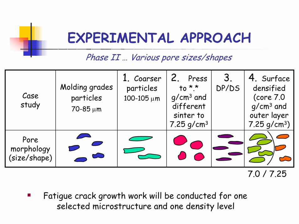
EXPERIMENTAL APPROACHPhase II … Various pore sizes/shapes
Pore morphology (size/shape)
4. Surface densified(core 7.0 g/cm3 and outer layer 7.25 g/cm3)
3.DP/DS
2. Press to *.*
g/cm3 and different sinter to
7.25 g/cm3
1. Coarser particles
100-105 µmMolding grades
particles70-85 µm
Case study
7.0 / 7.25
Fatigue crack growth work will be conducted for one selected microstructure and one density level

EXPERIMENTAL APPROACHOther experimental considerations …
Inclusion level is low shed light on pore and microstructure effects;
Low residual stress levels are critical to understand the true behavior of the materials and have a fair comparison basis:
- stress relief is done during tempering - additional stress relieving may be needed after machining.

FUTURE WORK …Finish the open/closed porosity study;
Do a parallel study high temperature/long time sintering vs. DP/DS to determine the processing parameters allowing the same amount of closed porosity;Analyze microstructural results and microhardness for the two heat treatments on both the homogeneous and non-homogeneous materials for each of the microstructures;
Perform static tensile tests to get YS, Young’s modulus, UTS for all cases;
Check the residual stress level and decide if an additional stress relieving is needed after the post-sintering heat treatment;
Prepare samples for the life study (200 dog-bone samples) and the fatigue crack growth work (16 compact tension specimens);
Machine all the samples;
Start fatigue work.