fast charging install guide - s3-eu-west-1.amazonaws.com
TRANSCRIPT

Fast Charging
Solo 3 - CommercialInstall Guide
Solo 3 - Commercial PP-D-210110-2 Install Guide S3-UK-D-IG

Essential safety information
The Solo 3 is designed and manufactured to be safe provided they are professionally installed, used and maintained in accordance with the manufacturer’s instructions. They should be installed by approved electrical installers in accordance with national and local regulations applicable at the time of installation, e.g. BS7671:2018.
The Solo 3 is designed to be connected to one dedicated AC supply only. The property must comply with minimum BS7671 standards before installation commences and the supply must be adequately rated for the additional load required for EV charging*.
As of the 1st January 2019 either a dedicated Type B or a Type A two or four-pole RCD/RCBO with 6mA DC protection must be used for protection (6mA DC protection is included inside the Solo 3).
Please note: : A DC leakage fault in the vehicle may “blind” a type “AC” RCD and render it ineffective.BS7671 requires a “mechanical” RCD/RCBO that switches all poles (including neutral) be installed in the circuit.BS7671 also requires 2 pole isolation for RCD/RCBOs.
*Subject to Array load management/current clamp being installed - see page 5 for more.
Install location
The Solo 3 can be fitted inside or outside. The installer should consult the site owner to establish their preferred installation location. This should take into consideration the cable length (distance to vehicle being charged), risk of vehicle impact and obstruction of access, etc.
IET code of practice states the Solo 3 be mounted to a permanent structure at a height of 750mm-1200mm (see Fig. 1). This is to assist those with accessibility requirements and reduce the risk of vehicle impact.
Fig. 1 - Location and dimensions
This document details the installation guidance for the Solo 3 (Commercial) a variant of the Solo 3 product family. If you’re unsure which model you are planning to install, please contact your account manager or Pod Point directly.
The Solo 3 can be installed in all circumstances except on individual dwellings where the power supply is located within the property. This EVSE is appropriate for commercial use only, including public infrastructure, workplace charging, and shared residential properties.
This charger requires installation by approved electrical installers in accordance with national and local regulations applicable at the time of installation, e.g. BS7671:2018.
Universal SocketCharger decal may vary
Speed category Fast charging
Charging speed Up to 7kW or 22kW
Product family Solo 3
Solo 3 - Commercial
Consider the additional connector depth from wall when charge cable is in use (approximately 150mm should be added).
Solo 3 - Commercial PP-D-210110-2 Install Guide S3-UK-D-IG
750-1200mm (code of practice)500-1500mm (BS7671 & BS EN61851)Installation height to centre of socket

Technical details
The Solo 3 is a Class I/II rated device, pollution degree 3 for 230V / 400V AC 50Hz systems and is IP54 and IK10 rated.
The Solo 3 is designed to meet the following European standards: BS EN IEC 61851-1:2019 (BS7671 722.511.101), Low Voltage Directive (LVD) 2014/35/EU and electromagnetic compatibility (EMC) Directive 2014/30/EU. Sockets and EV charging connectors comply with IEC 62196-1.
During manufacture each Solo 3 has been functionally tested for safety using BS EN 61010 & BS EN 61557 approved equipment.
IEC 61851: (6.3.2 Optional functions)
The universal socketed Solo 3 includes an electro-mechanical means for locking Type 2 connectors (as per IEC 61851-1, IEC 62196-2 and BS7671). The Solo 3 does not support (State D) ventilation for lead acid battery vehicles.All Solo 3s include variable overcurrent protection for differing charging cable ratings that maybe used.
Earth arrangements The Solo 3 includes a safety monitoring system to detect low voltage supplies, failed earths and potential earth-neutral faults. If a fault condition is detected the charge cycle is ended or prevented.
Note: When used as part of an Array system this feature is disabled and an earth link between input and output terminals should be fitted
A standalone Solo 3 (not part of an Array Charging network) may be connected directly to a TN-C-S (PME) earthing system without any special arrangements. Solo 3 complies with regulation 722.411.4.1 (v) of BS7671
Please see our installation documents webpage for additional information on the earthing arrangements for EVSE.
RCD protection: All Solo chargers manufactured after 2018 include 6mA DC vehicle fault protection and only Type A RCD/RCBOs are required at source.
Fig. 2 - RCD Markings
Type A Type B The RCD may include additional markings.
Please note: A vehicle DC leakage fault can “blind” certain type “AC” RCDs.
Surge Protection Devices (SPDs):
See BS7671: section 443 guidance.
The Solo 3 includes Type 3 protection against transient over voltages (+/-2kV Line-Earth and +/-1kV Line-Line as a requirement of EN 61000-6-1). The guidance on risk calculation in section 443.5 in most cases is difficult and it may be prudent that Type 2 protection should be installed at the source of supply, especially if life support equipment or business operations could be affected. Type 1 SPD may also be desired in certain higher risk locations.
Solo 3 - Commercial
Solo 3 - Commercial PP-D-210110-2 Install Guide S3-UK-D-IG

Transformers If a galvanically isolated transformer is required, it should be placed upstream of the EVSE. The Neutral output feed of the transformer shall be connected to EVSE earth (creating a TN-S system) and the PE taken before any RCD and MCB (if 2 pole MCB is used). Resistance measured between the EVSE earth and PE Earth must be less than 100 ohms. Do not connect the output earth/neutral of the transformer to a PME earthed system. Upstream transformer RCD protection may be of Type AC (if fitted). Downstream RCD protection is still required.Transformers should be rated for 100% duty cycle at 10% above rated charge current.
● Transformers should be located in a dry, well-ventilated area.
● Transformers shall comply with the requirements of IEC 61558-1 and IEC 61558-2-4.
● Direct EVSE connection of an EVSE to a three-phase IT system is prohibited. Contact us if an IT network is to be used with a single-phase Solo 3 as it will report an earth fault.
Isolation and switching for security, safety and maintenance To ensure that the Solo 3 can be “turned off” to enhance security and enable maintenance activities, a double-pole isolator suitably rated must be installed within the circuit (2-pole RCBO can provide this isolation).
If an optional isolator switch is requested, it should be mounted at a height of between 500mm and 1500mm and should be rated greater than 32A. Any devices located outside should comply with pollution degree level 3 for safety and reliability. Installation of any accessory devices must also comply to relevant BS7671 and/or local regulations.
Installation procedure
Please note:
● The information in this section is advice and may not alway be applicable
● National or local regulations not related to electrical works are not covered in this guide. Relevant H&S at work, building regulations, etc. must be adhered to.
● Not following regulations may void warranty
The installer should confirm the wall that the EVSE is intended to be located is structurally appropriate, If applicable, prior to any installation work beginning (drilling or fitting of conduit and cables etc), allow the customer to visualise where the EVSE will be installed. Consider cable trip hazards and access routes. Once the customer has confirmed the location is acceptable, the location may be marked up and installation can commence.
• To maintain IK10, at least 80mm long screws should be used for brick or concrete, and it is recommended penny washers be included.
• Before drilling commences, ensure that the installation wall has been checked for electric cabling or pipework with a suitable detector.
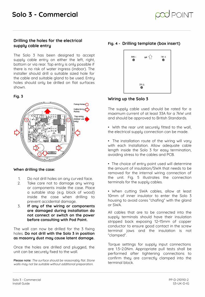
Once the location and height of the Solo 3 have been decided, the installer can begin marking the wall with indicator points to locate the unit. Use the box insert as the drilling template for the 3 mounting holes (Fig. 4).
Please note: If any groundworks are required (cable trenching or earth electrode fitment) it is advisable to check if underground services could be present before commencement. Plans for undergrounds services may be available at: linesearchbeforeudig.co.uk
Solo 3 - Commercial
Solo 3 - Commercial PP-D-210110-2 Install Guide S3-UK-D-IG
Drilling the holes for the electrical supply cable entry The Solo 3 has been designed to accept supply cable entry on either the left, right, bottom or via rear. Top entry is only possible if there is no risk of water ingress (indoor). The installer should drill a suitable sized hole for the cable and suitable gland to be used. Entry holes should only be drilled on flat surfaces shown.
Fig. 3
When drilling the case:
1. Do not drill holes on any curved face.2. Take care not to damage any wiring
or components inside the case. Place a suitable stop (e.g. block of wood) inside the case when drilling to prevent accidental damage.
3. If any of the wiring or components are damaged during installation do not connect or switch on the power before consulting with Pod Point.
The wall can now be drilled for the 3 fixing holes. Do not drill with the Solo 3 in position as masonry dust may cause latent damage.
Once the holes are drilled and plugged, the unit can be securely fixed to the wall.
Please note: The surface should be reasonably flat. Stone walls may not be suitable without additional preparation.
Fig. 4 - Drilling template (box insert)
Wiring up the Solo 3
The supply cable used should be rated for a maximum current of at least 33A for a 7kW unit and should be approved to British Standards.
• With the rear unit securely fitted to the wall, the electrical supply connection can be made.
• The installation route of the wiring will vary with each Installation. Allow adequate cable length inside the Solo 3 for easy termination, avoiding stress to the cables and PCB.
• The choice of entry point used will determine the amount of insulation/SWA that needs to be removed for the internal wiring connection of the unit. Fig. 5 illustrates the connection terminals for the supply cables.
• When cutting SWA cables, allow at least 10mm of inner insulator to enter the Solo 3 housing to avoid cores “chafing” with the gland or SWA.
All cables that are to be connected into the supply terminals should have their insulation stripped back exposing 12~15mm of copper conductor to ensure good contact in the screw terminal jaws and the insulation is not “clamped”.
Torque settings for supply input connections are 1.5~2.0Nm. Appropriate pull tests shall be performed after tightening connections to confirm they are correctly clamped into the terminal block.
Solo 3 - Commercial
Solo 3 - Commercial PP-D-210110-2 Install Guide S3-UK-D-IG

Solo 3 supply wiring
Ensure that incoming cables are connected to the appropriate terminal as follows:Fig. 5.
Fig. 6.
Supply input cable wiringLive: brownLive 2: blackLive 3: greyNeutral: blueEarth: green/yellow
Screened cable* (Array data cable)Signal (usually red)Screen (outer braiding of cable)*Voltage rating must be equivalent to supply cable if located in the same containment
Wiring of Array Controller. When included as part of an Array system (multiple chargers connected to the same power supply) the Solo 3 requires the external control input signal to be provided by an Array Module. The Array Controller feeds data to many Solo 3s, allowing the available supply to be shared equally. When wiring, the screen or “braiding” of the signal wire should be connected to the GND terminal of the blue screw terminal block CON9/J301.
Note: Terminals require no more than 0.5Nm of torque. Overtightening terminals can sever the cables and also damage the terminals.
Array Module wiring:
Setup and testing of Array systems.
Each Solo 3 must be enabled over Wi-Fi. Details of the supply limit must be provided and each unit commissioned at time of installation.When all units are commissioned and power is “on” confirm all chargers display a blue LED with pink flash.
Switch off the supply to the Array Module at the distribution board (not to the Solo 3s). All units connected to the Array Module should enter an error state (red LED) if working normally as loss of the data signal must force a fault condition.
Switch the Array Module back on and the Solo 3 should resume normal operation. Connect a Solo 3 to a vehicle or a 10A simulated load and leave charging for 20 seconds. If the Solo 3 errors, check the location and correct fitment of the CT clamp at the distribution board. The Array Module must always report more current to the Solo 3 than the Solo 3’s rate of charge.
Please see our technical documents webpage for additional information on the Array systems
Single-phase Solo 3 wiring
Three-phase Solo 3 wiring
Solo 3 - Commercial
Solo 3 - Commercial PP-D-210110-2 Install Guide S3-UK-D-IG

Setting up the Solo 3
Current rating, cable overcurrent protection and Load curtailment settings must be set before testing and final assembly of the unit. Set the DIP switch (dual inline package) to the required settings as shown in table A. Use a pen or similar implement to slide the switches to their desired positions. By default, switch 3 should be set to “ON” (10A rating). The DIP switches should be set only when the unit is powered off.
Table A.
DIP Switch 5 Set to ON for tethered Solo 3s. (disables charge cable proximity measurement)DIP Switch 4 for home chargers only (set to off)DIP Switch 1, 2 and 3 Set to ON will disable the unit
Notes:
Overcurrent limit to IEC 61851 = 10%For Renault Zoe do not set below 10A (2.4kW).
The Solo 3’s internal dynamic overcurrent protection safeguards against long term cable overcurrent but not short circuit fault conditions.
Minimum cable size shown does not consider voltage drop (length of cable) or routing methods that may affect its operating temperature.
As a general guidance MCB ratings assume an 80% “thermal” derating factor, please refer to the manufacturers datasheet.
System wiring
Typically an additional small consumer unit will be fitted as few existing distribution boards support a 3rd split load required for EVSE, or an Array Board will be fitted that may require a dedicated supply. When an additional unit is installed, screw terminal junction box(es) should be installed at the incoming supply. If there are any safety concerns regarding the existing board the customer should be made aware.Never use IDC terminals for the installation.
If a consumer unit includes a spare non-RCD protected circuit, this may be used to supply the additional “mini” consumer unit. Use recommended torque settings for all MCB, RCD and terminal blocks.
Supply Cable
The size of the supply cable used should be designed for a maximum current of 33A (7kW Solo 3) and be approved to relevant standards. The installing party is liable for the appropriate design and sizing of the electrical cabling and (if required) communication cabling for each installation.
Fig. 7 Typical Solo 3 installation layout.
Final electrical testing
To meet the BS7671 (18th edition) requirements for testing of an electrical installation: ● Visually check the installation, including the existing
electrical installation, for any issues.● Check the condition of any existing bonding. If any
issues are found, correct if possible or advise customer if work is beyond the scope of the installation.
● Verify characteristics of the electrical supply at the origin of the installation to confirm its suitability for the additional load.
● Check the service head and cables are serviceable and advise as necessary if issues are identified.
● Check for exposed cables and ensure any missing blanks are replaced.
● Confirm the new circuit insulation resistance.● Confirm the polarity of the installation is correct.● Where applicable, confirm the earth electrode
resistance is within acceptable tolerances.
Solo 3 - Commercial
Solo 3 - Commercial PP-D-210110-2 Install Guide S3-UK-D-IG

● The mechanical operation of residual current devices, including the rated trip current and at five times the rated current.
● A test or calculated measurement of the prospective fault current.
● Functional verification using an EV simulator confirming operation of the Solo 3.
● If a vehicle is available, check the vehicle charges normally for a short time.
● If the Pod Point EV simulator is available, test fault state and DC 6mA functions of the Solo 3.
Note: At the time of this document’s publication there are no specific standards for 6mA DC testing. If ramp tests are conducted, false readings are possible if the test equipment has too fast a ramp up time.
When checking internal safety systems of the Solo 3, disconnection of the vehicle/tester may be required to reset these systems.
Pairing the Solo 3 to a Wi-Fi network Detailed Solo 3 connection guide can be found pod-point.com/technical/installation
On power up of the Solo 3 the front LED should illuminate white. To connect the Solo 3 to a Wi-Fi network do the following: ● Search for “podpoint” Wi-Fi network on your
mobile device and connect to it.
● On the device’s web browsers address bar type: 192.168.1.1 then “Enter” or “OK”.
● A page displaying available networks will show. Select the desired network and enter the network password. Press “Connect” at the bottom of the page.
Note: The page will remain displayed but inactive after “Connect” has been pressed.
● Power cycle the Solo 3 and wait for 1 minute. The LED should change to blue with a short pink flash when it has connected.
● If the status LED remains white, you may need to restart the charger again and verify the settings (see notes at end of this guide).
Fitting the front of the charger Once the wiring, testing and setup of the Solo 3 is completed, the front cover can be fitted in place.
Prior to fitting the front cover, visually check the internal wiring will not interfere with assembly. Dress if needed and remove any debris that may have entered during installation.
Check that the front cover mating seal is in place before fitting the cover to the housing. The front cover can then be secured in place using the 6 screws.
Remote diagnostics
When connected to the internet via Wi-Fi the charger will provide information on supply voltage(s), status of the incoming earth, charging current, temperature, rating of connected cable, etc. This data is primarily used for internal diagnostic purposes but is also used for energy usage displayed in the Pod Point App. In exceptional circumstances Pod Point may contact the site/unit owner if an abnormality is detected.
Theft of the Pod Point Solo 3
All Solo 3 EVSE include a unique MAC address to identify itself which is programmed into the silicon and cannot be changed. If a unit is reported as stolen and connection to the Pod Point Network is attempted, it can be placed permanently out of service. Array configured Pod Point chargers do not work as standalone units.
Additional product documents
We host our technical documentation across two pages via Pod-Point.com
Technical documents
Installation documents
Or scan the QR code here to get to our installerdocuments page
Solo 3 - Commercial
Solo 3 - Commercial PP-D-210110-2 Install Guide S3-UK-D-IG

Troubleshooting Wi-Fi connection problems
Sometimes Wi-Fi routers block the connection of devices for various reasons. These may be related to the total number of connected devices, bugs in the router's ARP table, password errors and other system settings.
If it is known the correct network and password have been entered (the device used for setting up may capitalise the 1st password character by default etc.) and the Solo 3 fails to connect after it has been restarted, a restart of the Wi-Fi router may cure the issue. The router should refresh the ARP table if conflicts existed.
Solo 3 supports 802.11 bgn Wi-Fi networks. AC is not supported. Ensure 2.4Ghz Wi-Fi is enabled on the router.
Check to make sure the default router password has not been changed and is no longer that 15 characters.
Check the security settings on the router have not been changed. Solo 3s use WPA2 by default.
Check the router's settings have not been modified to limit the number of users it will allow to connect.
Some low cost Wi-Fi routers have a maximum limit of connected devices they can support. If possible remove a device from the network and retry.
If a managed IT network is in use, the addition of the Solo 3 using the MAC address may be the only option. The MAC address can be provided by Pod Point from the PSL number of the unit which can then be included in the router’s “allowlist”.
Some Technicolour routers will only allow connection after the Solo 3's MAC address is added to the allowlist, after which the Solo 3 can be added in the usual way.
Solo 3’s cannot connect to networks that require an email address or where Terms and Conditions need to be agreed.
Wi-Fi security
If a “guest” network can be setup on the router (most ISP provided routers do not have this feature), limiting connection to one device with access limited only to the internet gives security conscious users some peace of mind.
Setting up an allowlist on a router adds an additional layer of security from attackers. This requires some level of IT knowledge to add the various MAC addresses. It also makes the connection of any future devices more difficult. Using the Wi-Fi router's SSID and password will not automatically allow connection.Viewing a router’s list of connected devices should reveal the Solo 3 as “Mysimplelink” followed by a number (MAC address). This MAC address may be used for the setting up of an allowlist.
WPS and PIN number access are regarded as insecure and should be disabled in the router settings if not used.
Cable and adaptor warning
IEC 61851-1 dictates that in-cable adaptors must be approved by the vehicle or the charge point manufacturer. In the interests of safety Pod Point do not approve the use of any in-cable adaptors for customer use as they can and do override safety features.
Adaptors/cables that change operational states of the EVSE are forbidden under terms of IEC 61851-1. These cables (commonly used for energy management) are not approved. Bypassing fundamental safety systems of the Solo 3 can compromise electrical safety. Charging cables cannot be used as “extension” leads. The “CP” pin in the plug is intentionally made shorter to prevent this.
Please check both plugs and sockets on any equipment for damage or debris before every use. Ensure all connectors can be fully plugged into the vehicle and charge point before use. Vehicle, cable or charge point manufacturers may not cover damaged cables under terms of their warranty.
Solo 3 - Commercial
Solo 3 - Commercial PP-D-210110-2 Install Guide S3-UK-D-IG

Commissioning of the Solo
It is important that all Pod Point EVSE are commissioned once they have been installed. Failure to do so will mean the EVSE are not covered by warranty, and the end user will not be able to access the charging point via the Pod Point App.
Commissioning of Commercial Solo chargers:
To commission a commercial Pod Point charger you will need to complete the commission form at:pod-point.com/3rd-party-commissioning
Solo Smart Charger
Testing of functionalities
When power is turned on, the lights on the Pod Point Solo should change colours as follows:
1. Establishing communication with server (takes up to 1 min) - white
2. Communication established, car not plugged - Blue flashing
An EV simulator is required for functionality tests.
1. Unlock mode - Blue flashing pink
2. Standby - Flashing green
3. Charge - Green
4. Fault - Solid or flashing red
If the test procedure fails at any stage please contact Pod Point.
Solo 3 - Commercial PP-D-210110-2 Install Guide S3-UK-D-IG
