farris - the national board of boiler and pressure … · 2017-03-20 · national board inspection...
TRANSCRIPT

1

2

3

4

5

��
NATIONAL BOARD INSPECTION CODE • PART � — INSTALLATION
ducing boiler pressure into the low-pressure system:
1) the failure of the pressure-reducing valve so that it remains wide open; and
2) the possibility of the bypass valve being open.
b) It is necessary therefore, to determine the flow under both circumstances (a) and (b) and check that the size of the safety valve under either condition will be adequate. The following formula should be used:
1) steam flow, W in lbs/hr through the pressure-reducing valve
W = AKC
where,A = internal area in sq. in. of the inlet
pipe size of the pressure-reducing valve (ref. 2.5)
K = flow coefficient for the pressure-reducing valve (see 2.4)
C = flow of saturated steam through a 1 sq. in. pipe at various pressure dif-ferentials from Table S2.3-a, Table S2.3-b, or Table S2.3-c.
2) steam flow, W in lbs/hr through the by-pass valve
W = A1 K1 C1
where,A1 = internal area in sq. in. of the pipe
size of the bypass around the pres-sure-reducing valve
K1 = flow coefficient for the bypass valves (see 2.4)
C1 = flow of saturated steam through a 1 sq. in. pipe at various pressure dif-ferentials from Table S2.3-a, Table S2.3-b, and Table S2.3-c.
s2.4 steam flow when flow CoeffICIents are not
known
a) It is possible that the flow coefficients K and K1 may not be known and in such instances for approximating the flow, a factor of 1/3 may be substituted for K and 1/2 for K1.
The formulas in S2.3 then becomes:
W = 1/3 AC for the capacity through the pressure-reducing valve; and
W = 1/2 A1 C1 for the capacity through the bypass valve.
b) Caution should be exercised when substitut-ing these factors for the actual coefficients since this method will provide approximate values only and the capacities so obtained may in fact be lower than actual. It is rec-ommended that the actual flow coefficient be obtained from the pressure-reducing valve manufacturer and reference books be consulted for the flow coefficient of the bypass valve.
s2.5 two-stage Pressure- reduCIng valve statIons
The safety relief valve for two-stage pressure-reducing valve stations shall be sized on the basis of the high-side pressure and the inlet size of the first pressure-reducing valve in the line. If an intermediate pressure line is taken off between the pressure-reducing valves then this line and the final low side shall be protected by safety relief valves sized on the basis of the high-side pressure and the inlet size of the first pressure-reducing valve. See Table S2.5.
6

2�
NATIONAL BOARD INSPECTION CODE • PART 2 — INSPECTION
The return to normal condition such as the restart of the burner, the silencing of an alarm, or stopping of a feed pump should be noted. A sluggish response could indi-cate an obstruction in the connections to the boiler.
b) The operation of a submerged low water fuel cutoff mounted directly in a steam boiler shell should be tested by lowering the boiler water level carefully. This should be done only after being assured that the water level gage glass is indicating correctly.
c) On a high-temperature water boiler, it is often not possible to test the control by cutoff indication, but where the control is of the float type, externally mounted, the float chamber should be drained to check for the accumulation of sediment.
d) In the event controls are inoperative or the correct water level is not indicated, the boiler shall be taken out of service until the unsafe condition has been corrected.
e) All automatic low water fuel cutoff and wa-ter feeding devices should be examined by the Inspector to ensure that they are prop-erly installed. The Inspector should have the float chamber types of control devices disassembled and the float linkage and connections examined for wear. The float chamber should be examined to ensure that it is free of sludge or other accumulation. Any necessary corrective action shall be taken before the device is placed back into service. The Inspector should check that the operating instructions for the devices are readily available.
f) Check that the following controls/devices are provided:
1) Each automatically-fired steam boiler is protected from over pressure by not less than two pressure operated con-trols, one of which may be an operating control.
2) Each automatically-fired hot-water boiler is protected from over-tempera-ture by not less than two temperature operated controls, one of which may be an operating control.
3) Each hot-water boiler is fitted with a thermometer that will, at all times, in-dicate the water temperature at or near the boiler outlet.
2.2.11 recorDs revieW
a) A review of the boiler log, records of main-tenance, and feedwater treatment should be made by the Inspector to ensure that regular and adequate tests have been made on the boiler and controls.
b) The owner or user should be consulted re-garding repairs or alterations, if any, which have been made since the last inspection. Such repairs or alterations should be re-viewed for compliance with the jurisdic-tional requirements, if applicable.
2.2.12 DescriPtion anD concerns of sPecific tYPes of boilers
The following details are unique to specific type boilers and should be considered when performing inspections along with the general requirements as previously outlined.
2.2.12.1 Watertube boilers
a) Typically constructed of drums, headers, and tubes, watertube boilers are used to produce steam or hot water commonly in large quantities. They range in size and pressure from small package units to extremely large field erected boilers with pressures in excess of 3000 psig (41.37 MPa gage). These boilers may be fired by many types of fuels such as wood, coal,
7

8

��
NATIONAL BOARD INSPECTION CODE • PART 2 — INSPECTION
construction. The set pressure of additional devices may exceed the MAWP, as permit-ted by the original code of construction.
c) Verify nameplate capacity and, if pos-sible, compare to system capacity require-ments.
d) Check identification on seals and ensure they match nameplates or other identifica-tion (repair or reset nameplate) on the valve or device.
2.5.3 conDitions
a) Check for evidence that the valve or device is leaking or not sealing properly.
b) Seals for adjustments should be intact and show no evidence of tampering.
c) Connecting bolting should be tight and all bolts intact.
d) The valve or device should be examined for deposits or material buildup.
e) Evidence of rust or corrosion should be checked.
f) Check for damaged or misapplied parts.
g) If a drain hole is visible, ensure it is not clogged with debris or deposits.
h) Check for test gags left in place after pres-sure testing of the unit.
i) Bellows valves shall be checked to ensure the bonnet vent is open or piped to a safe location. The vent shall not be plugged since this will cause the valve set pressure to be high if the bellows develops a leak. Leakage noted from the vent indicates the bellows is damaged and will no longer protect the valve from the effects of back pressure.
2.5.4 inservice insPection requirements for Pressure
relief Devices
a) Inspect inlet piping and ensure it meets the requirements of the original code of con-struction. For pressure relief valves, check that the inlet pipe size is not smaller than the device inlet size.
b) Inspect discharge piping and ensure it meets the original code of construction. Check that the discharge pipe size is not smaller than the device outlet size.
c) Check that the valve drain piping is open.
d) Check drainage of discharge piping.
e) Check that inlet and discharge piping are not binding or placing excessive stress on the valve body which can lead to distortion of the valve body and leakage or malfunc-tion.
f) Check the condition and adequacy of piping supports. Discharge piping should be supported independent of the device itself.
g) Check for possible hazards to personnel from the valve discharge or discharge pipe.
h) Check that there are no intervening isola-tion valves between the pressure source and the valve inlet or between the valve outlet and its point of discharge. (Isolation valves may be permitted in some pressure vessel service. See Part 1, 5.3.6(e), and ju-risdictional requirements. Isolation valves are not permitted for power boilers, heating boilers, or water heaters.)
i) A change-over valve, which is used to in-stall two pressure relief devices on a single vessel location for the purpose of switching from one device to a spare device, is not considered a block valve if it is arranged
9

10

NATIONAL BOARD INSPECTION CODE PART 2 - INSPECTION
5.3.3 NEW BUSINESS OR DISCONTINUANCE OF BUSINESS FORM (NB-4)
FORM NB-4 NEW BUSINESS OR DISCONTINUANCE
USED BY AUTHORIZED INSPECTION AGENCIES
To: JURISDICTION 1. DATE OF SERVICE
New iRsweAee business q High pressure boiler 2. Not~ce of: 3. Hlae(vsdate 4. Type of object: Low pressure boiler
q Pressure vessel
5. OBJECT 1 6. OWNER'S NO. 1 7. JURISDICTION NO. I 8. NATIONAL BOARD NO, 1 9. NAME OF MANUFACTURER ! I I I
10. NAME OF OWNER
11. NAME OF OWNER INCLUDING COUNTY
12. LOCATION OF OBJECT INCLUDING COUNTY
13. USER OF OBJECT (IF SAME AS OWNER SHOW "SAME")
14. DATE OF LAST CERTIFICATE INSPECT., IF ANY 15. CERTIFICATE ISSUED 16. REASON FOR DISCONTINUANCE OR CANCELLATION 1 OYes O M I ClPhys.mndition O G n o f use q Other
17. REMARKS (USE REVERSE SIDE)
18. By: CHIEF INSPECTOR BRANCH OFFICE
This form may be obtained from The National Board of Boiler and Pressure Vessel Inspecton, 1055 Crupper Ave., Columbus, OH 43229 NB-4 Rev. 2
11

12

141
NATIONAL BOARD INSPECTION CODE • PART 2 — INSPECTION
TABLE S2.10.4Maximum Allowable Working Pressure for Stayed Surfaces per ASME Section 1, PG 46.1
Thickness of Stayed Surface
Staybolt Spacing (Maximum Pitch)
3-1/2 4 4-1/8 4-1/4 4-3/8 4-1/2 4-5/8 4-3/4 4-7/8 5 5-1/8 5-1/4 5-3/8 5-1/2 5-5/8 5-3/4 5-7/8 6
0.19 85 65 61 58 55 52 49 46 44 42 40 38 36 35 33 32 30 29
0.2 95 72 68 64 61 57 54 51 49 46 44 42 40 38 37 35 34 32
0.21 104 80 75 71 67 63 60 57 54 51 49 46 44 42 40 39 37 36
0.22 115 88 82 78 73 69 66 62 59 56 53 51 49 46 44 42 41 39
0.23 125 96 90 85 80 76 72 68 65 61 58 56 53 51 48 46 44 43
0.24 136 104 98 92 87 82 78 74 70 67 64 61 58 55 53 50 48 46
0.25 148 113 106 100 95 89 85 80 76 72 69 66 63 60 57 55 52 50
0.26 160 122 115 108 102 97 92 87 82 78 75 71 68 65 62 59 57 54
0.27 172 132 124 117 110 104 99 94 89 85 80 77 73 70 67 64 61 59
0.28 185 142 134 126 119 112 106 101 96 91 87 82 79 75 72 69 66 63
0.29 199 152 143 135 127 120 114 108 103 97 93 88 84 81 77 74 71 68
0.3 213 163 153 144 136 129 122 116 110 104 99 95 90 86 82 79 76 72
0.31 227 174 164 154 146 138 130 123 117 111 106 101 96 92 88 84 81 77
0.32 242 185 174 164 155 147 139 132 125 119 113 108 103 98 94 90 86 82
0.33 258 197 185 175 165 156 148 140 133 126 120 115 109 104 100 95 91 88
0.34 273 209 197 185 175 165 157 148 141 134 128 122 116 111 106 101 97 93
0.35 290 222 209 197 185 175 166 157 149 142 135 129 123 117 112 107 103 99
0.36 307 235 221 208 196 185 176 166 158 150 143 136 130 124 119 114 109 104
0.37 324 248 233 220 207 196 185 176 167 159 151 144 137 131 125 120 115 110
0.38 342 262 246 232 219 207 196 185 176 167 159 152 145 138 132 127 121 116
0.39 360 275 259 244 230 218 206 195 185 176 168 160 153 146 139 133 128 122
0.4 379 290 273 257 242 229 217 206 195 185 177 168 160 153 147 140 134 129
0.41 398 304 286 270 255 241 228 216 205 195 185 177 169 161 154 147 141 135
0.42 417 320 300 283 267 252 239 227 215 204 195 185 177 169 162 155 148 142
0.43 437 335 315 297 280 265 251 237 225 214 204 194 185 177 169 162 155 149
0.44 480 367 345 325 307 290 275 261 247 235 224 213 203 194 186 178 170 163
0.45 502 384 361 340 321 304 287 272 259 246 234 223 213 203 194 186 178 171
0.46 524 402 378 356 336 317 300 285 270 257 245 233 222 212 203 194 186 178
0.47 547 419 394 371 350 331 314 297 282 268 255 243 232 222 212 203 194 186
0.48 571 437 411 387 365 345 327 310 294 280 266 254 242 231 221 212 203 194
0.49 595 456 428 404 381 360 341 323 307 292 278 264 252 241 230 220 211 202
TS = Tensile Strength (55,000) C = 2.1 if 7/16 in. or lesst = Thickness of Stayed Surface P = t2 x SC/p2 C = 2.2 if more than 7/16 in.S = 13,800 p = Maximum PitchP = MAWP
13

14

15

16

17

18

��
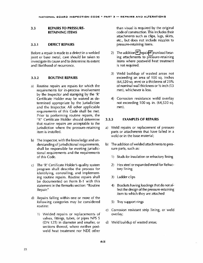
NATIONAL BOARD INSPECTION CODE • PART 3 — REPAIRS AND ALTERATIONS
1.7.3 general rules
The general rules of the National Board “VR” certification program apply only to the repair of National Board capacity certified ASME Code Section I “V” stamped, Section IV “HV” marked, and Section VIII “UV” stamped pres-sure relief valves that:
a) Have been in service or have been exposed to environmental or other conditions such that there is reason to question their ability to perform equivalent to the standards for new valves; or
b) Any or all of the valve’s external adjustment seals have been broken, opened, or other-wise disturbed, regardless of the valve’s age or service status.
1.7.4 rePair of nuClear valves
Provided that the requirements of Supplement 8 and applicable requirements of these rules are met, the “VR” certificate may be extended to apply to the repair of any ASME Code Section III, Class 1, 2, or 3, pressure relief devices that have been capacity certified by the National Board and have been in service, regardless of their intended function, in a nuclear system.
1.7.5 issuanCe and reneWal of tHe “vr” CERTIFICATE OF
AUTHORIZATION
1.7.5.1 general
Authorization to use the stamp bearing the of-ficial National Board “VR” symbol as shown in Section 5 of this Part, will be granted by the National Board pursuant to the provisions of the following administrative rules and procedures. Supplement 9 of this Part, provides rules for the repair of ASME Section III “NV” stamped pressure relief devices.
1.7.5.2 issuanCe of CertifiCate
a) Repair organizations, manufacturers, as-semblers, or users that make repairs to the American Society of Mechanical Engineers (ASME) Code symbol, stamped or marked (as applicable), and The National Board of Boiler and Pressure Vessel Inspectors (National Board) capacity certified pres-sure relief valves may apply to the National Board for a Certificate of Authorization to use the “VR” symbol. The National Board may at any time, through the NBIC Com-mittee, modify the regulations concerning the issuance and use of such valve repair symbol. All such modified regulations shall become binding upon holders of valid Valve Repair Certificates of Authorization.
b) Authorization to use the “VR” stamp may be granted or withheld by the National Board in its absolute discretion. If authorization is granted and proper administrative fees paid, a certificate of authorization will be issued evidencing permission to use such a sym-bol, expiring on the triennial anniversary date. The certificate will be signed by the National Board Chairman of the National Board of Trustees, the Executive Director, or any other duly authorized officer.
c) The certificate shall list the physical, per-manent address of record for the certificate holder’s shop/plant. For field-only scopes, this address of record shown on the Certifi-cate of Authorization is where administra-tive, technical, and quality aspects of the business are controlled.
1.7.5.3 reneWal of CertifiCate
The Certificate of Authorization is renewable every three (3) years subject to a review of the Quality System by a representative of the National Board, review and acceptance of the representative’s report by the National Board, and successful completion of capacity
19

��
NATIONAL BOARD INSPECTION CODE • PART 3 — REPAIRS AND ALTERATIONS
1) If either or both of these replacement valves fail to meet the above criteria, the applicant shall document the cause of the noted deficiencies and actions taken to guard against future occurrence. Upon acceptance of this information by the National Board, one (1) additional valve for each replace-ment valve that failed shall be repaired and tested. The valve(s) shall be of the same ASME Code Section, fluid and set pressure scope, as the valve previously failing to meet the test requirement.
2) Failure of this valve(s) to meet the ASME Code to which the valve was manufac-tured shall be cause for consideration by the National Board of revocation of the “VR” Certificate of Authorization or acceptance of alternative corrective action.
1.7.5.6 verifiCation testing alternatives
a) In such cases where all valves repaired by the applicant for a specified ASME Code Section or test fluid exceed the capabilities of the accepted testing laboratory, valves for that ASME Code Section or test fluid shall be selected as specified in 1.7.5.4, and a demonstration test shall be successfully performed in lieu of verification testing specified in 1.7.5.5 above. The demonstra-tion tests shall be conducted at a facility mutually agreeable to the National Board representative, the facility owner, and the applicant. The purpose of these tests is to demonstrate, in the presence of a National Board representative, that the repaired valves shall have adequate seat tightness at the maximum expected operating pres-sure prior to lifting, shall open within the required set pressure tolerance, operate consistently without chatter, and reclose within the required blowdown.
b) If a valve lift-assist device is used by the applicant to establish set pressure after re-pairs, this device must also be used to set the demonstration valves.
c) If either of these valves fail to meet the above criteria, then replacement valves shall be repaired and tested at a rate of two valves for each one that failed.
1) If either or both of these replacement valves fail to meet the above criteria, the applicant shall document the cause of the noted deficiencies and actions taken to guard against future occurrence. Upon acceptance of this information by the National Board, one (1) additional valve for each replace-ment valve that failed shall be repaired and tested. The valve(s) shall be of the same ASME Code section, fluid, and set pressure scope as the valve previously failing to meet the test requirement.
2) Failure of this valve(s) to meet the ASME Code to which the valve was manufac-tured shall be cause for consideration by the National Board of revocation of the “VR” Certificate of Authorization or acceptance of alternative corrective action.
1.7.6 use of tHe “vr” autHoriZation
1.7.6.1 teCHniCal requirements
The administrative requirements of 1.7 for use of the “VR” stamp shall be used in conjunction with the technical requirements for valve repair as described in Supplement 6 of the NBIC. Those requirements shall be mandatory when a “VR” repair is performed.
20

21

22
23

��
NATIONAL BOARD INSPECTION CODE • PART 3 — REPAIRS AND ALTERATIONS
d. The WPS followed shall be quali-fied for weld metal buildup in accordance with ASME Section IX. The nominal chemical analysis of the deposited weld metal shall be equivalent to the base material that is to be repaired. In addition, the nominal tensile strength of the deposited weld metal shall be equal to or exceed the specified minimum tensile strength and shall be based on the requirements of the welding consumable. If butt joints in the component being overlaid required postweld heat treatment (PWHT) by the code of construction, the WPS followed for the weld buildup shall be given PWHT.
e. The pressure-retaining item shall be taken out of service and internal contents emptied prior performing the weld metal buildup. The owner of the pressure-retaining item shall evaluate the flammability, volatility, or potential reaction of the contents that were in the vessel to assure safe working conditions during weld repair.
f. This method may be used more than once in the same areas to repair locally thinned areas; how-ever , the cumulative weld buildup for all repairs shall not exceed the thickness (t) of the component at any point.
g. Repairs using this method shall not cover more than 25% of the circumference of the component.
3) External weld buildup shall be applied in accordance with the following re-quirements:
a. The area to be repaired shall be ultrasonically scanned for wall
thickness, and the location and size of the thinned region shall be mapped.
b. The area requiring repairs and the boundaries of the weld buildup shall be marked on the external surface of the component.
c. The general design of the external weld buildup shall be in accor-dance with Figure 3.3.4.3-c. The finished weld buildup shall be circular, oval, or rectangular in shape.
d. The weld buildup shall extend, at full thickness, a minimum distance B in each direction beyond the boundaries of the thinned base metal area.
1. B = 3/4 Rt nom
2. R = outer radius of the com-ponent, or D/2
3. tnom = nominal wall thickness of the component
The thickness shall be sufficient to maintain the predicted life of the repair. Any corrosion allow-ance that is determined to be necessary shall be added to the value of B.
e. All edges of the weld buildup shall be tapered to the existing contour of the com-ponent, at a maximum angle (a) of 45°.
f. The thickness of the weld buildup shall be uniform except along tapered edges. As welded surfaces are acceptable provided they are free of coarse ridges and valleys and are suitable for any required nonde-structive examinations
g. All corners of the weld buildup shall have a minimum radius (r), not less than the overlay thickness.
24

��
NATIONAL BOARD INSPECTION CODE • PART 3 — REPAIRS AND ALTERATIONS
figure 3.3.4.3-brepairs for access openingsA badly wasted manhole flange may be removed and replaced with a ring-type frame as shown below. The requirements for flush patches shall be met. A full penetration weld is required. May be either double or welded from one side with or without a backing ring.
A badly wasted area around a handhole opening may be repaired by adding a ring, as shown below, on the inside of the object.
figure 3.3.4.3-cexternal overlay terms and definitions
L = length of area to be repaired along the axis of the component
C = length of area to be repaired along out-side circumference of the component
W = the completed thickness of the overlaya = the angle between the component and
the overlay (maximum 45°)B = 3/4 (R t) minimumR = nominal outside radius of the compo-
nentD = the nominal outside diameter of the
componentt = nominal wall thickness of the componentµ = remaining wall thickness of the component shall be 1/16 or greater.
Standard Manhole Opening
Backing Ring
Pressure Side
25

26

27

28

��
NATIONAL BOARD INSPECTION CODE • PART 3 — REPAIRS AND ALTERATIONS
5.9 stamPing requirements for Pressure relief deviCes
5.9.1 namePlates
Proper marking and identification of tested or repaired valves is critical to ensuring accep-tance during subsequent inspections, and also provide for traceability and identification of any changes made to the valve. All operations that require the valve’s seals to be replaced shall be identified by a nameplate as described in 5.9.2 or 5.9.4.
5.9.2 rePair namePlate
When a pressure relief valve is repaired, a metal repair nameplate stamped with the in-formation required below shall be securely attached to the valve adjacent to the original manufacturer’s stamping or nameplate. If not mounted directly on the valve, the nameplate shall be securely attached so as not to interfere with valve operation and sealed in accordance with the quality system. a) Prior to attachment of the repair nameplate,
the previous repair nameplate, if appli-cable, shall be removed from the repaired valve.
b) As a minimum, the information on the valve repair nameplate (See Figure 5.9.6-e) shall include:
1) The name of the repair organization preceded by the words “repaired by”;
2) The “VR” repair symbol stamp and the “VR” Certificate Number;
3) Unique identifier (e.g., repair serial number, shop order number, etc.);
4) Date of repair;
5) Set pressure;
6) Capacity and capacity units (if changed from original nameplate due to set pres-sure or service fluid change);
7) Type/Model number (if changed from original nameplate by a conversion. See Supplement S7.2; and
8) When an adjustment is made to correct for service conditions of superimposed back pressure and/or temperature or the differential between popping pressure between steam and air (See 4.5.2), the information on the valve repair name-plate shall include the:
a. Cold Differential Test Pressure (CDTP), and
b. Superimposed Back Pressure (BP) (only when applicable).
5.9.3 CHanges to original Pressure relief valve namePlate information
a) If the set pressure is changed, the set pres-sure, capacity, and blowdown, if applica-ble, on the original nameplate or stamping shall be marked out but left legible. The new capacity shall be based on that for which the valve was originally certified.
b) If the service fluid is changed, the capacity, including units, on the original nameplate or stamping shall be marked out but left legible. The new capacity shall be based on that for which the valve was originally certified, or if a conversion has been made, as described in Supplement S6.2 on the capacity certification for the valve as con-verted.
c) If the Type/Model number is changed, the Type/Model number on the original name-plate shall be marked out but left legible.
d) If the blowdown is changed, the blowdown on the original nameplate or stamping shall
29
�0
NATIONAL BOARD INSPECTION CODE • PART 3 — REPAIRS AND ALTERATIONS
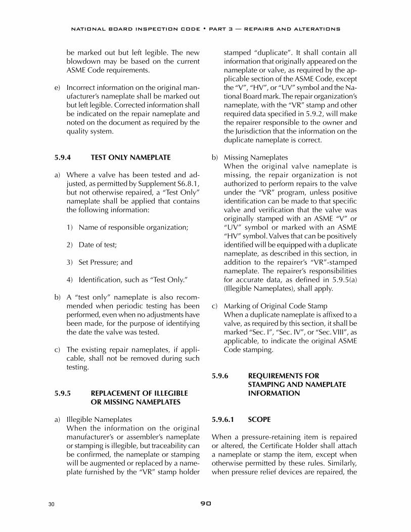
be marked out but left legible. The new blowdown may be based on the current ASME Code requirements.
e) Incorrect information on the original man-ufacturer’s nameplate shall be marked out but left legible. Corrected information shall be indicated on the repair nameplate and noted on the document as required by the quality system.
5.9.4 test onlY namePlate
a) Where a valve has been tested and ad-justed, as permitted by Supplement S6.8.1, but not otherwise repaired, a “Test Only” nameplate shall be applied that contains the following information:
1) Name of responsible organization;
2) Date of test;
3) Set Pressure; and
4) Identification, such as “Test Only.”
b) A “test only” nameplate is also recom-mended when periodic testing has been performed, even when no adjustments have been made, for the purpose of identifying the date the valve was tested.
c) The existing repair nameplates, if appli-cable, shall not be removed during such testing.
5.9.5 rePlaCement of illegible or missing namePlates
a) Illegible Nameplates When the information on the original
manufacturer’s or assembler’s nameplate or stamping is illegible, but traceability can be confirmed, the nameplate or stamping will be augmented or replaced by a name-plate furnished by the “VR” stamp holder
stamped “duplicate”. It shall contain all information that originally appeared on the nameplate or valve, as required by the ap-plicable section of the ASME Code, except the “V”, “HV”, or “UV” symbol and the Na-tional Board mark. The repair organization’s nameplate, with the “VR” stamp and other required data specified in 5.9.2, will make the repairer responsible to the owner and the Jurisdiction that the information on the duplicate nameplate is correct.
b) Missing Nameplates When the original valve nameplate is
missing, the repair organization is not authorized to perform repairs to the valve under the “VR” program, unless positive identification can be made to that specific valve and verification that the valve was originally stamped with an ASME “V” or “UV” symbol or marked with an ASME “HV” symbol. Valves that can be positively identified will be equipped with a duplicate nameplate, as described in this section, in addition to the repairer’s “VR”-stamped nameplate. The repairer’s responsibilities for accurate data, as defined in 5.9.5(a) (Illegible Nameplates), shall apply.
c) Marking of Original Code Stamp When a duplicate nameplate is affixed to a
valve, as required by this section, it shall be marked “Sec. I”, “Sec. IV”, or “Sec. VIII”, as applicable, to indicate the original ASME Code stamping.
5.9.6 requirements for stamPing and namePlate
information
5.9.6.1 sCoPe
When a pressure-retaining item is repaired or altered, the Certificate Holder shall attach a nameplate or stamp the item, except when otherwise permitted by these rules. Similarly, when pressure relief devices are repaired, the
30

FORM R-1 REPORT OF REPAIR in accordance with provisions of the National Board lnspection Code
I . performed by (name of repair organization) (Fonn R No.)
(PO No., lob No., etc.)
(address1
3. Location of installation name
(address)
4. Unit identification vssel) Name of original manufacturer
5. Identifying nos.: (National Board No.) (furisdiction %.) (other) (year built)
6. NBIC Edition1 Addenda: (addenda)
Original Code of Construction for Item:
Construction Code Used for Repair Performed: (namelsectionldivision)
(editionladdenda)
(editionladdenda)
7. Repair Type: Welded Graphite Pressure Equipment FRP Pressure Equipment 8. Description of work:
(use supplemental sheet, Form R 4 , if necessary)
Pressure Test, if applied psi MAWP psi 9. Replacement Parts. Attached are Manufacturer's Partial Data Reports or Form R-3s properly
completed for the following items of this report:
(name of part, item number, data report type, mg's name, and identifying stamp)
10. Remarks:
CERTIFICATE OF COMPLIANCE
1, , certify that to the best of my knowledge and belief the statements in this report are correct and that all material, construction, and workmanship on this Repair conforms to the National Board Inspection Code.
National Board " R Certificate of Authorization No. expires on Date Signed
(name of repair organization) (authorized representative)
CERTIFICATE OF INSPECTION
1, , holding a valid Commission issued by The National Board of Boiler and Pressure Vessel Inspectors and certificate of competency issuedwhawrequificd, by the jurisdiction of and employed by of have inspected the work described in this report on and state that to the best of my knowledge and belief this work complies with the applicable requirements of the National Board lnspection Code. By signing this certificate, neither the undersigned nor my employer makes any warranty, expressed or implied, concerning the work described in this report. Furthermore, neither the undersigned nor my employer shall be liable in any manner for
any personal injury, property damage or loss of any kind arising from or connected with this inspection.
Date Signed Commissions (inspector) (National Board and Jurisdiction No.)
This form may be obtained from The National Board of Boiler and Pressure Vessel Inspectors, 1055 Crupper Ave., Columbus, OH 43229 NB-66 Rev. 11
31

�0�
NATIONAL BOARD INSPECTION CODE • PART 3 — REPAIRS AND ALTERATIONS
5.13.5 form nr-1, NUCLEAR COmPONENTS ANd SySTEmS IN NUCLEAR POWER PLANTS
name of “NR” certifi cate holder PO no., job no., etc.
address
name
address
FORM NR–1 REPORT OF REPAIR MODIFICATION OR REPLACEMENT TO NUCLEAR COMPONENTS AND SYSTEMS IN NUCLEAR POWER PLANTS
1. Work performed by
2. Owner
3. Name, address, and identifi cation of nuclear power plant
4. System
5a. Items that Required Repair, Modifi cation, or Replacement Activities
Identifi cation Construction Code Activity
No.Type of Item
Mfg. Name
Mfg. SerialNo.
Nat’l Bd No.
Juris.No. Other
Year Built
Name/Section/Division
Edition/Addenda
Code Case(s)
Code Class
Repair/Mod/Replace
1
2
3
4
5
6
7
8
9
10
11
12
5b. Items Installed During Replacement Activities
Identifi cation Construction Code
Type of Item
Installed or Replaced 5a Item No.
Mfg. Name
Mfg.Serial No.
Nat’l Bd No.
Juris.No. Other
Year Built
Name/Section/Division
Edition/Addenda
Code Case(s)
Code Class
6. ASME Code Section XI applicable for inservice inspection:
7. ASME Code Section XI used for repairs, modifi cations, or replacements:
8. Construction Code used for repairs, modifi cations, or replacements:
9. Design responsibilities
10. Tests conducted: hydrostatic pneumatic design pressure pressure psi Code Case(s)
This form may be obtained from The National Board of Boiler and Pressure Vessel Inspectors, 1055 Crupper Ave., Columbus, OH 43229 NB-81
1 2
4
5
6
8 9 11 12 15 16 17 18 19 19 19 20
10 21 22 23 24 25 26 27 28 29 29 29
30 30 30
31 31 31
32 32 32
33
34 34
32

�0�
NATIONAL BOARD INSPECTION CODE • PART 3 — REPAIRS AND ALTERATIONS
11. Description of work
12. Remarks
CERTIFICATE OF COMPLIANCE
I, , certify that to the best of my knowledge and belief the statements made in this report are correct and the repair, modifi cation, or replacement activities described above conform to Section XI of the ASME Code and the National Board Inspection Code “NR” rules.National Board Certifi cate of Authorization No. to use the “NR stamp expires , NR Certifi cate Holder
Date , Signed
CERTIFICATE OF INSPECTION
I, , holding a valid commission issued by The National Board of Boiler and Pressure Ves-sel Inspectors and certifi cate of competency issued by the jurisdiction of and employed by
of
have inspected the repair, modifi cation, or replacement described in this report on , and state that to the best of my knowledge and belief, this repair, modifi cation, or replacement activity has been completed in accordance with
Section XI of the ASME Code and the National Board Inspection Code “NR” rules.By signing this certifi cate, neither the undersigned nor my employer makes any warranty, expressed or implied, concerning the work described in this report. Furthermore, neither the undersigned nor my employer shall be liable in any manner for any personal injury, property damage, or a loss of any kind arising from or connected with this inspection.Date , Signed Commissions
(use of properly identifi ed additional sheet[s] or sketch[es] is acceptable)
(name) (authorized representative) (title)
(inspector) (National Board and jurisdiction no.)
This form may be obtained from The National Board of Boiler and Pressure Vessel Inspectors, 1055 Crupper Ave., Columbus, OH 43229 NB-81
39
40
41
42 43
44
45 46 47
4849
50 51
52
52 53 54
33

�0�
NATIONAL BOARD INSPECTION CODE • PART 3 — REPAIRS AND ALTERATIONS
5.13.6 form nvr-1, NUCLEAR PRESSURE RELIEF dEvICES
FORM NVR–1 REPORT OF REPAIR MODIFICATION OR REPLACEMENT OF NUCLEAR PRESSURE RELIEF DEVICES
1. Work performed by
2. Work performed for
3. Owner
4. Name, address, and identifi cation of nuclear power plant
5. a: Repaired pressure relief device:
b: Name of manufacturer
c: Identifying nos.
d: Construction Code
6. ASME Code Section XI applicable for inservice inspection:
7. ASME Code Section XI used for repairs, modifi cations, or replacements:
8. Construction Code used for repairs, modifi cations, or replacements:
9. Design responsibility
10. Opening pressure: Blowdown (if applicable) %. Set pressure and blowdown adjustment
made at: using
11. Description of work: (include name and identifying number of replacement parts)
12. Remarks:
CERTIFICATE OF COMPLIANCEI, , certify that to the best of my knowledge and belief the statements made in this report are correct and the repair, modifi cation, or replacement of the pressure relief devices described above conforms to Section XI of the ASME Code and the National Board Inspection Code “VR” and “NR” rules.National Board Certifi cate of Authorization No. to use the “VR” stamp expires , National Board Certifi cate of Authorization No. to use the “NR” stamp expires , Date , Signed
CERTIFICATE OF INSPECTIONI, , holding a valid commission issued by The National Board of Boiler and Pressure Vessel Inspectors and certifi cate of competency issued by the jurisdiction of andemployed by of have inspected the repair, modifi cation, or replacement described in this report on , and state that to the best of my knowledge and belief, this repair, modifi cation, or replacement has been completed in accordance with Sec-tion XI of the ASME Code and the National Board Inspection Code “VR” and “NR” rules.By signing this certifi cate, neither the undersigned nor my employer makes any warranty, expressed or implied, concerning the repair, modifi cation, or replacement described in this report. Furthermore, neither the undersigned nor my employer shall be liable in any manner for any personal injury, property damage, or loss of any kind arising from or connected with this inspection.Date , Signed Commissions
This form may be obtained from The National Board of Boiler and Pressure Vessel Inspectors, 1055 Crupper Ave., Columbus, OH 43229 NB-160
(name of certifi cate holder) (PO No., Job No., etc.)
(address)
(name)
(name)
(address)
(type) (mfg’s serial no.) (Nat’l Bd no.) (service) (size) (year built)
(name/section/division) (edition) (addenda) (Code Case[s]) (code class)
(edition) (addenda) (Code Case[s])
(edition) (addenda) (Code Case[s])
(edition) (addenda) (Code Case[s])
(inspector) (National Board and jurisdiction no.)
1 2
3
4
5
7
9
10 11 12 13 14 17
18 19 19 19 19
30 30 30
31 31 31
32 32 32
33
35 36
37 38
39
40
41
42 43
42 4345 44 46 47
4849
50 5152
52 53 54
34

�0�
NATIONAL BOARD INSPECTION CODE • PART 3 — REPAIRS AND ALTERATIONS
30. Identify the edition, addenda, and any ap-plicable code cases of the ASME Section XI code used for the repair or replacement activity.
31. Identify the edition, addenda, and any ap-plicable code cases of the ASME Section XI code for the repair/replacement activity.
32. Identify the edition, addenda, and any applicable code cases of the construction code for the repair/replacement activity.
33. Identify the organization responsible for design or design reconciliation, if a p p l i -cable.
34. Identify the type of pressure test (e.g., hydro-static, pneumatic, or design) and applied test pressure. Also indicate any code cases used in connection with the pressure test.
35. Indicate the set pressure of the valve.
36. Indicate blowdown, if applicable, as a percentage of set pressure.
37. Indicate the repair organization’s name and address.
38. Indicate the medium (steam, air, etc.) used for the adjustment of set pressure and, if applicable, blowdown.
39. State exact scope of work for the repair/replacement activity. If necessary attach additional data, sketch, Form R-4, etc. If additional data is attached, so state.
40. Indicate any additional information pertain-ing to the work.
41. Type or print name of authorized represen-tative from the certificate holder.
42. Indicate National Board Certificate of Au-thorization number.
43. Indicate month, day, and year the certificate expires.
44. Name of the certificate holder which per-formed the identified work.
45. Enter date certified.
46. Signature of authorized representative from the certificate holder.
47. Title of authorized representative.
48. Type or print name of Authorized Nuclear Inservice Inspector.
49. Indicate the jurisdiction where the work is performed.
50. Indicate Authorized Nuclear Inspector’s employer.
51. Indicate address of Authorized Nuclear Inservice Inspector’s employer (city and state or province).
52. Indicate month, day, and year of inspec-tion by the Authorized Nuclear Inservice Inspector.
53. Signature of Authorized Nuclear Inservice Inspector.
54. National Board Commission number of the Authorized Nuclear Inservice Inspector, including endorsements, jurisdiction, and certificate of competency numbers.
35

���
NATIONAL BOARD INSPECTION CODE • PART 3 — REPAIRS AND ALTERATIONS
g) Weld seams parallel to a knuckle shall be located no closer to the knuckle than the point of tangency of the knuckle unless the weld is radiographically examined. Weld seams not located in the knuckle are preferred. See Figure S1.2.11.5-b.
h) Patches shall be made from material that is at least equal in quality and thickness to the original material.
s12.11.3 rePair of staYed firebox sHeets grooved or Wasted at tHe mudring
a) Grooved or wasted firebox sheets having greater than 60% of the minimum required thickness remaining may be repaired by weld buildup provided the wastage does not extend below the waterside surface of the mudring and the strength of the struc-ture will not be impaired. If extensive weld-ing is required, the affected area shall be removed and replaced with a flush patch.
b) If the sheet thickness has been reduced to less than 60% of the minimum required thickness, the affected section shall be removed and replaced with a flush patch.
c) If wastage and grooving extends below the mudring waterside surface and if the plate thickness remaining has been reduced to less than the minimum required thickness, the affected section shall be removed and replaced with a flush patch.
d) Flush patches shall be arranged to include the mudring rivets and at least the first row of staybolts above the mudring.
s1.2.11.4 mudring rePairs (see figure s1.2.11.4)
a) Pitted and wasted sections of mudrings may be built up by welding provided the strength of the mudring will not be im-paired. Where extensive weld buildup is
figure s1.2.11.3stayed firebox sheet grooved or Wasted at mudring
Firebox Sheets
First Staybolt Row
Sheet Wasted Below Mudring Waterside
Mudring Rivet Mudring
figure s1.2.11.4mudring repairs
mudringremove fire box sheets for access
full penetration weld
36

���
NATIONAL BOARD INSPECTION CODE • PART 3 — REPAIRS AND ALTERATIONS
s7.10 guide to JurisdiCtions for autHoriZation of oWners-users to make adJustments to Pressure relief valves
s7.10.1 general
The Jurisdiction may authorize properly trained and qualified employees of boiler and pressure owners-users or their designees to restore set pressure and/or performance of pressure relief valves. All external adjustments shall be re-sealed with a seal identifying the responsible organization and a metal tag that identifies the organization and the date the adjustment shall be installed.
s7.10.2 training
a) The user shall establish a documented in-house training program. This program shall establish training objectives and provide a method of evaluating the training effective-ness. As a minimum, training objectives for knowledge level shall include:
1) Applicable ASME Code and NBIC re-quirements;
2) Responsibilities within the organiza-tion’s quality system;
3) Knowledge of the technical aspects and mechanical skills for making set pres-sure and/or blowdown adjustments to pressure relief valves;
4) Knowledge of the technical aspects and mechanical skills for marking of pres-sure relief valve adjustments.
b) If the user established a designee, the des-ignee shall establish a training program and make their documentation available to the user and the jurisdictional authority.
s7.10.3 doCumentation
Each user shall document the evaluation and acceptance of an employee’s or designee’s qualifications.
s7.10.4 qualitY sYstem
a) A written quality system shall be estab-lished by either the user or the designee with a written description available to the jurisdictional authority.
b) The written description shall include at a minimum:
1) Calibration of Test Equipment: This shall describe a system for the calibra-tion of measuring and test equipment. Documentation of these calibrations shall include the standard used and the results. Calibration standards shall be calibrated against the equipment having valid relationships to nationally recognized standards.
2) Valve Testing, Setting, and Sealing: This system shall include provisions that each valve shall be tested, set, and all external adjustments sealed according to the requirements of the applicable ASME Code Section and S7.10.1(a).
3) Valve Marking: An effective marking system shall be established to ensure proper marking of the metal tag re-quired by S7.10.1(a). The written qual-ity system shall include a description of drawing of the metal tag.
s7.10.5 external adJustments
Only external adjustments to restore the re-quired set pressure and/or performance of a pressure relief valve shall be made under the provisions of S7.10.1(a).
37

�00
NATIONAL BOARD INSPECTION CODE • PART 3 — REPAIRS AND ALTERATIONS
removed before the weld repair of the part is performed. Removal of the defect shall be verified by suitable NDE as required.
d) Consideration shall be given to the condi-tion of the existing material, especially in the weld preparation area.
s7.12.1 Welding ProCedure sPeCifiCations
Welding shall be performed in accordance with Welding Procedure Specifications (WPS) qualified in accordance with the original code of construction. When this is not possible or practicable, the WPS may be qualified in ac-cordance with Section IX of the ASME Code.
s7.12.2 standard Welding ProCedure sPeCifiCations
A “VR” Certificate Holder may use one or more applicable Standard Welding Procedure Speci-fications shown in 2.3 of this part.
s7.12.3 PerformanCe qualifiCation
Welders or welding operators shall be qualified for the welding processes that are used. Such qualification shall be in accordance with the requirements of the original code of construc-tion or Section IX of the ASME Code.
s7.12.4 Welding reCords
The “VR” Certificate Holder shall maintain a record of the results obtained in welding proce-dure qualifications, except for those qualifica-tions for which the provisions of Supplement S7.10.2 are used, and of the results obtained in welding performance qualifications. These records shall be certified by the “VR” Certificate Holder and shall be available to the National Board.
s7.12.5 Welders’ identifiCation
The “VR” Certificate Holder shall establish a system for the assignment of a unique identifi-cation mark to each welder/welding operator qualified in accordance with the requirements of the NBIC. The “VR” Certificate Holder shall also establish a written procedure whereby welded joints can be identified as to the welder or welding operator who made them. This procedure shall use one or more of the fol-lowing methods and shall be described in the quality control system written description. The welder’s or welding operator’s identification mark may be stamped (low stress stamp) adja-cent to welded joints made by the individual, or the “VR” Certificate Holder may keep a documented record of welded joints and the welders or welding operators used in making the joints.
s7.12.6 Welders’ ContinuitY
The performance qualification of a welder or welding operator shall be affected when one of the following conditions occur:
a) When the welder or welding operator has not welded using a specific process during a period of six months or more, their quali-fications for that process shall expire.
b) When there is specific reason to question their ability to make welds that meet the specification, the qualification that sup-ports the welding that is being performed shall be revoked. All other qualifications not questioned remain in effect.
s7.13 Heat treatment
s7.13.1 PreHeating
Preheating may be employed during welding to assist in completion of the welded joint (2.5.1 of
38