(excerpts from boiler, pressure vessel …excerpts from boiler, pressure vessel and piping codes and...
TRANSCRIPT

INDUSTRY, LABOR & HUMAN RELATIONS 49ILHR 41-42 Appendix B
ILHR 41-42
APPENDIX B
(EXCERPTS FROM BOILER, PRESSURE VESSEL AND PIPING CODES ANDSTANDARDS )
Excerpts from the following boiler, pressure vessel and piping codes and standards arereproduced here strictly for reference : ASME Sections I, IV and VIII and ANSI/ASME B31 .1 .This informarion has been included to provide a general idea as to the requirements of these
codes and standards . Users of this information must be cautioned that these excerpts do notprovide complete guidelines for inspection, installation, operation and manufacturing .
Only portions of each code and standard thought to be frequently used by persons nothaving direct access to the complete documents have been included . It must be noted thatthese codes and standards change on a periodic basis as indicated in s . ILHR 41 .10 . Those
who are bound by the rules of ch . ILHR 41 must avail themselves of the applicable code
section or standards listed in s . ILHR 41 a 10. Refer to ch. ILHR 42 for rules applying to
repairs, alterations, and miscellaneous requirements .
Register, May, 1994, No .. 461

50 WISCONSIN ADMINISTRATIVE CODEILHR 41-42 Appendix B
EXCERPTS FROM :
ASME BOILER AND PRESSURE VESSEL CODE
SECTION I
POWER BOILERS
1992 EDITION
Register, May, 1994, No, . 461

INDUSTRY, LABOR. & HUMAN RELATIONS 51ILHR 41-42 Appendix B
PREAMBLE
This Code covers rules for construction ofpower boilers, electric boilers, miniatureboilers, and high-temperature water boilersto be used in stationary service and includesthose power boilers used in locomotive,portable, and traction service . Reference toa paragraph includes all the subparagraphsand subdivisions under that paragraph .
The Code does not contain rules to coverall details of design and construction.Where complete details are not given, it isintended that the manufacturer, subject tothe acceptance of the Authorized Inspector,shall provide details of design andconstruction which will be as safe asotherwise provided by the rules in the Code .
The scope of jurisdiction of Section Iapplies to the boiler proper and to the boilerexternal piping .
Superheaters, economizers, and otherpressure parts connected directly to theboiler without intervening valves shall beconsidered as parts of the boiler proper, andtheir construction shall conform to Section Irules .
Boiler external piping shall be consideredas that piping which begins where the boilerproper terminates at :
(a) the first circumferential joint forwelding end connections ; or
(b) the face of the first flange inbolted flanged connections ; or
(c) The first threaded joint in thattype of connection; andWhich extends up to and including the
valve or valves required by this Code .
ASME code Certification (including DataForms and Code Symbol Stamping), and/orinspection by the Authorized Inspector,when required by this Code, is required forthe boiler proper and the boiler external
Pipmg-Construction rules for materials, design,
fabrication, installation, and testing of theboiler external piping are contained inASME B31 .1, Power Piping, Piping beyondthe valve or valves required by Section I isnot within the scope of Section I, and it isnot the intent that the Code Symbol Stampbe applied to such piping or any otherpiping .
The material for forced-circulation boilers,boilers with no fixed steam and water line,and high-temperature water boilers shallconform to the requirements of the Code .All other requirements shall also be metexcept where they relate to special featuresof construction made necessary in boiler ofthese types, and to accessories that aremanifestly not needed or used in connectionwith such boilers, such as water gages andwater columns .
Reheaters receiving steam which haspassed through part of a turbine or otherprime mover and separately fired steamsuperheaters which are not integral with theboiler are considered fired pressure vesselsand their construction shall comply withCode requirements for superheaters,including safety devices . Piping between thereheater connections and the turbine or other
Register, May, 1994, No,. 461

52 WISCONSIN ADMINISTRATIVE CODEILHR 41-42 Appendix B
prime mover is not within the scope of theCode .
A pressure vessel in which steam isgenerated by the application of heat resultingfrom the combustion of fuel (solid, liquid,or gaseous) shall be classed as a fired steamboiler .
Unfired pressure vessel in which steam isgenerated shall be classed as unfired steamboiler with the following exceptions :
(a) vessels known as evaporators or heatexchanges; -
(b) vessels in which steam is generated bythe use of heat resulting from operation of aprocessing system containing a number ofpressure vessels such as used in themanufacture of chemical and petroleumproducts .
Unfired steam boilers shall be constructedunder the provisions of Section I or SectionVIII .
Expansion tanks required in connectionwith high-temperature water boilers shall beconstructed to the requirements of Section Ior Section VIII .
A pressure vessel in which an organic fluidis vaporized by the application of heatresulting from the combustion of fuel (solid,liquid, or gaseous) shall be constructedunder the provisions of Section I . Vessels inwhich vapor is generated incidental to theoperation of a processing system, containinga number of pressure vessels such as used inchemical and petroleum manufacture, arenot covered by the rules of Section L
Register, May, 1994, No. 461

INDUSTRY, LABOR & HUMAN RELATIONS 53ILHR 41-42 Appendix B
PART PGGENERAL REQUIREMENTS FOR ALL
METHODS OF CONSTRUCTION
GENERAL
PG-1 SCOPE(b) No steam is generated within the
The requirements of Part PG apply topower boilers and high pressure,. high-temperature water boilers and to parts andappurtenances thereto and shall be used inconjunction with the specific requirements inthe applicable Parts of this Section thatpertain to the methods of construction used .
PG-2 SERVICE LIMITATIONS
PG-2.1 The rules of this Section areapplicable to the following services :(a) boilers in which steam or other vapor is
generated at a pressure of more than 15
psig;(b) high-temperature water boilers intended
for operation at pressures exceeding 160psig and/or temperatures exceeding. 250°F .
PG-2.2 For services below those specifiedin PG-2.1 it is intended that rules of SectionIV apply; however, boilers for such servicesmay be constructed and stamped inaccordance with. this Section provided allapplicable requirements are met .
PG-2.3 Coil-type hot water boilers wherethe water can flash into steam when releaseddirectly to the atmosphere through amanually operated nozzle may be exemptedfrom the rules of this Section provided thefollowing conditions are met .
(a) There is no drum header, or othersteam space.
coil .(c) Tubing outside diameter does not
exceed 1 in .(d) Pipe size does not exceed NPS
3/4 .(e) Nominal water capacity does not
exceed 6 gal .(f) Water temperature does not
exceed 350°F.(g) Adequate safety relief valves and
controls are provided .
Register, May, 1994, No 461

54ILHR 41-42 Appendix B
WISCONSIN ADMINISTRATIVE COD E
VENTS ANDINSTRUMENTATIO N
SINGLE INSTALLATIO N
--~~~ PG°58 3 .1PG-583 2
MULTIPLE INSTALLATION
COMMON HEADERF _
DRAIN --~~ STEAM DRUM
CONTROL DEVIC EPG-60
VENT INLET HEADER
Of used )
DRAIN ` SU~ERNEATE p
L.
PG-684~
HOT REHEAT ~"`~~~ -~---- ----~-DRAIN REhEATER
::D:TR A
VENT
PG -684
COLO REHEATIN
PG-58.3 7 EOQ ER
PG••71
LEVEL INDICATORSPG-60
SURFACE BLOWPG 58 .3.7 CONTINUOUS
--- BLOW-DQ- -- CHEMICAL FEED
DRUM SAMPLE
F' r
SOOT BLOWERS PG-685
~~ ~-~--~-- SINGLE INSTALLATION
MAiN STEA MP(, ;8 3 1
f-t SOOT BLOWERS PG-68 ..5-v- MULTfPL ELlNSTA LLATIO N
PG-58 3 .2 --DRAIN COMMONDRAIN HEA D E R
WATER DRUMPG-58 3:.6
BLOW-OFFSINGLE AND MULTIPLEINSTAL.LATIONS
~ - - - SINGLE BOILER
f~-+-CG--{/b-- -- - SINGLE BOILER
~TWO OR MORE BOILERS
U, S---d4--~-1/F-~ SOURC E
in -~
LL
ORAIN
PG-58,3 7
BOILER NO t
BOIlERN02 FEOFROMACOMMO N~
~> rn REGULATING vALVE5
~d-~si BOILERNO r -D~----{
y_ TWOORMORE
~a BOILER NO 2 BOILERSFEDFROM~~4 A COMMON SOURC E
ADMINISTRATIVE JURISDICTION & TECHNICAL RESPONSIBILITY
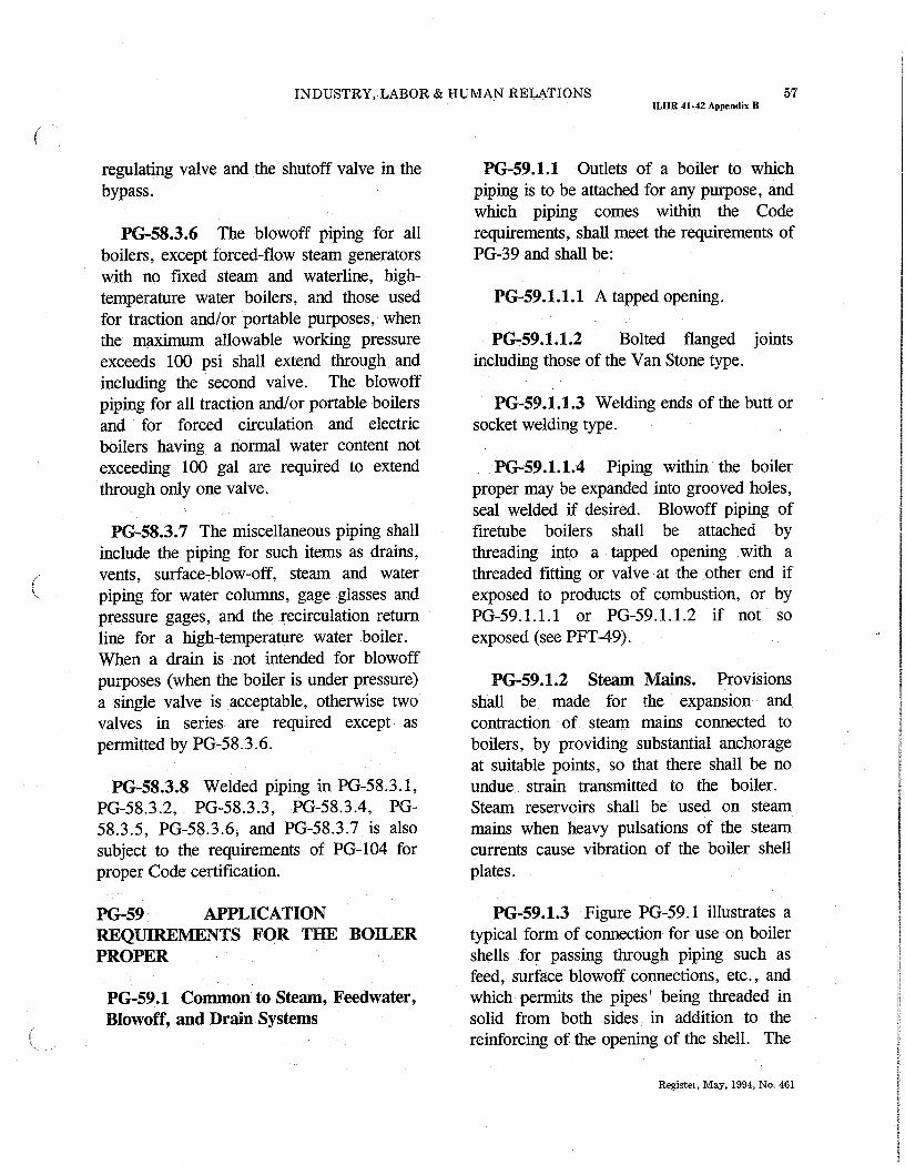
Boiler Proper - The ASME Boiler and Pressure Vessel Code (ASME BPVC) has total administrative jurisdiction and technicalresponsibility (refer to Section I Preamble) .
• Boiler External Piping and Joint - The ASME BPVC has total administrative jurisdiction (mandatory certificationby Code Symbol stamping. ASME Data Forms, and Authorized Inspection) of Boiler External Piping and Joint.The ASME Section Committee B31 .1 has been assigned technical responsibility.
O Non-Boiler External Piping and Joint - Not Section I jurisdiction (see applicable ASME B31 Code) .
FIG. PG-58 .3.1 CODE JURISDICITONAL LINIITS FOR PIPING - DRUM TYPE BOILERS
Register, May, 1994, No, . 461

INDUSTRY, LABOR & HUMAN RELATIONS 55ILHR 41-42 Appendix B
Turbine valve orcode stop valvePG5a31 /
SuperheaterTurbine
- - To equipmen t
Reheate r
Convection
and radiantsection
Economizer
><P__ _--__-T _
~~-----
I---i--1 (Start-up systemmay vary to suit
boiler manufacturerCondenser
r -
~,.
Boiler feed pump~---
~►-~4~--;-'W~- -~-~';--
L ADMINISTRATIVE JURISDICTION & TECHNICAL RESPONSIBILIT Y
- Boiler Proper - The ASME Boiler and Pressure Vessel Code (ASME BPVC) has total administrative jurisdiction andtechnical responsibility (refer to Section I Preamble) .
•- Boiler External Piping and Joint - The ASME BPVC has total administrative jurisdiction (mandatory certificationby Code Symbol stamping, ASME Data Forms, and Authorized Inspection) of Boiler External Piping and Joint .The ASME Section Committee B31 .1 has been assigned technical responsibility .
O-Non-Boiler External Piping and Joint - Not Section I jurisdiction ((see applicable ASME B31 Code) .
FIG. PG-58.3 .2 CODE JURISDICTIONAL LIMITS FOR PIPING - FORCED-FLOW STEAM GENERATOR WITH NO FIXEDSTEAM OR WATERLINE
Register, May, 1994, No. 461

56ILHR 41-42 Appendix B
WISCONSIN ADMINISTRATIVE COD E
BOILER EXTERNAL PIPINGAND BOILER PROPER
CONNECTIONS
PG-58 OUTLETS AND EXTERNALPIPING
PG-58.1 General . The rules of thissubparagraph apply to the boiler externalpiping as defined in the Preamble .
PG-58.2 Boiler External PipingConnections to Boilers . All boiler enternalpiping connected to a boiler for any purposeshall be attached to one of the type of jointslisted PG-59.1 .1 .1, PG-59.1 .1 .2, and PG-59.1 .1 .3 .
PG-58.3 Boiler External Piping . Thefollowing defines the Code JurisdictionalLimits of the boiler external piping systems,including general requirements, valves, andinspection. The limits are also shown inFig. PG-58.3 .1 and Fig . PG-58 .3 .2. Thematerials, design, fabrication, installation,and testing shall be in accordance withASME B31 .1, Power Piping .
PG-58.3.1 The steam piping connected tothe boiler drum or to the superheater outletheader shall extend up to and including thefirst stop valve in each connection, except asrequired by PG-58 .3.2. In the case of asingle boiler and prime mover installation,the stop vaive required herein may beomitted provided the prime mover throttlevalve is equipped with an indicator to showwhether the valve is open or closed and isdesigned to withstand the requiredhydrostatic pressure test of the boiler .
PG-58.3.2 When two or more boilers areconnected to a common steam header, theconnection from each boiler having amanhole opening shall be fitted with twostop valves having an ample free-blow drainbetween them. The boiler external pipingincludes all piping from the boiler proper upto and including the second stop valve andthe free-blow drain valve .
PG-58.3.3 The feedwater piping for allboilers, except high-temperature waterboilers and forced-flow steam generatorscomplying with PG-53 .3.5, shall extendthrough the required stop valve and up toand including the check valve except asrequired by PG-58 .3 .4 . On a single boiler-turbine unit installation the boiler feedshutoff valve may be located upstream fromthe boiler feed check valve .
If a feedwater heater or heaters meeting therequirements of Part PFH are installedbetween the required stop valve and theboiler, and are fitted with isolation andbypass valves, provisions must be made toprevent the feedwater pressure fromexceeding the maximum allowable workingpressure of the piping or feedwater heater,whichever is less . Control and interlocksystems are permitted in order to preventoverpressure o
PG-58.3.4 When two or more boilers arecd iOiii a Vviiuiivn source, tie yipiiig Siaii
be up to and including a globe or regulatingvalve located between the check valverequired in PG-58 .3 .3 and the source ofsupply . If the regulating valve is equippedwith an isolation valve and a bypass valve,the piping shall be up to and including boththe isolation valve downstream from the
Register, . May, 1994, No., 461
INDUSTRY, LABOR & HUMAN RELATIONS 57ILHR 41-42 Appendix B
regulating valve and the shutoff valve in thebypass .
PG-58.3.6 The blowoff piping for allboilers, except forced-flow steam generatorswith no fixed steam and waterline, high-temperature water boilers, and those usedfor traction and/or portable purposes, whenthe maximum allowable working pressureexceeds 100 psi shall extend through and111llUding the second vaive . aie vlowofa
piping for all traction and/or portable boilersand for forced circulation and electricboilers having a normal water content notexceeding 100 gal are required to extendthrough only one valve .
PG-58.3.7 The miscellaneous piping shallinclude the piping for such items as drains,vents, surface-blow-off, steam and waterpiping for water columns, gage glasses andpressure gages, and the recirculation returnline for a high-temperature water boiler .When a drain is not intended for blowoffpurposes (when the boiler is under pressure)a single valve is acceptable, otherwise twovalves in series are required except aspermitted by PG-58 .3 .6 .
PG-58.3.8 Welded piping in PG-58 .3.1,PG-58 .3 .2, PG-58.3 .3, PG-58 .3 .4, PG-
58.3 .5, PG-58 .3 .6, and PG-58.3 .7 is alsosubject to the requirements of PG-104 forproper Code certification.
PG-59.1 .1 Outlets of a boiler to whichpiping is to be attached for any purpose, andwhich piping comes within the Coderequirements, shall meet the requirements ofPG-39 and shall be :
PG-59.1.1 .1 A tapped opening .
PG-59.1 .1.2 Bolted flanged jointsincluding those of the Van Stone type .
PG-59.1.1 .3 Welding ends of the butt orsocket welding type .
PG-59.1.1.4 Piping within the boilerproper may be expanded into grooved holes,seal welded if desired . Blowoff piping offiretube boilers shall be attached bythreading into a tapped opening with athreaded fitting or valve at the other end ifexposed to products of combustion, or byPG-59.1 .1 .1 or PG-59.1 .1 .2 if not so
exposed (see PFT-49) :
PG-59.1.2 Steam Mains . Provisionsshall be made for the expansion andcontraction of steam mains connected toboilers, by providing substantial anchorageat suitable points, so that there shall be noundue strain transmitted to the boiler.Steam reservoirs shall be used on steammains when heavy pulsations of the steamcurrents cause vibration of the boiler shellplates .
PG-59 APPLICATIONREQUIREMENTS FOR THE BOILERPROPER
PG-59.1 Common to Steam, Feedwater,Blowoff, and Drain Systems
PG-59.1 .3 Figure PG-59 .1 illustrates atypical form of connection for use on boilershells for passing through piping such asfeed, surface blowoff connections, etc ., andwhich permits the pipes' being threaded insolid from both sides in addition to thereinforcing of the opening of the shell . The
Register, May, 1994, No . 461

58ILHR 41-42 Appendix B
WISCONSIN ADMINISTRATIVE CODE
~ ... ~
pipes shall be attached as provided in PG-59.1 .1 .
In these and other types of boilers whereboth internal and external pipes making acontinuous passage are employed, the boilerbushing or its equivalent shall be used .
PG-59.2 Requirements for FeedwaterConnections . The feedwater shall beintroduced into a boiler in such a manneruiai, uic vva tci will i30L ue uiNciuugeu uuccuy
against surfaces exposed to gases of hightemperature or to direct radiation from thefire. For pressures of 400 psi or over, thefeedwater inlet through the drum shall befitted with shields, sleeves, or other suitablemeans to reduce the effects of temperaturedifferentials in the shell or head .Feedwater, other than condensate returns asprovided for in PG-59 .3.6, shall not beintroduced through the blowoff .
PG-59.3 Requirements for Blowoffs
PG-59.3.1 A Blowoff as required hereinis defined as a pipe connection providedwith valves located in the external pipingthrough which the water in the boiler maybe blown out under pressure, exceptingdrains such as are used on water columns,gage glasses, or piping to feedwaterregulators, etc ., used for the purpose ofdetermining the operating condition of suchequipment. Piping connections usedpriniarily for contiriuous operation, such asdeconcentrators on continuous blowdownsystems, are not classed as blowoffs but thepipe connections and all fittings up to andincluding the first shutoff valve shall beequal at least to the pressure requirementsfor the lowest set pressure of any safetyvalve on the boiler drum and with thecorresponding saturated-steam temperature .
PG-59.3 .2 A surface blowoff connectionshall not exceed NPS 21/2 , and the internalpipe and the terminal connection for theexternal pipe, when used, shall form acontinuous passage, but with clearancebetween their ends and arranged so that theremoval of either will not disturb the other .A properly designed steel bushing, similar toor the equivalent of those shown in Fig . PG-59.1, or a flanged connection shall be used .
PG-59.3.3 Each boiler except forced-flowsteam generators with no fixed steam andwaterline and high-temperature water boilersshall have a bottom blowoff outlet in directconnection with the lowest water spacepracticable for external piping conforming toPG-58.3 .6 .
PG-59.3.4 All waterwalls and waterscreens which do not drain back into theboiler, and all integral economizers, shall beequipped with outlet connections for ablowoff or drain line and conform to therequirements of PG-58 .3 .6 or PG-58.3 .7 .
PG-59.3.5 Except as permitted forminiature boilers in Part PMB, the minimumsize of blowoff connections shall be NPS 1,and the maximum size shall be NPS 21/2,except that for boilers with 100 sq ft ofheating surface or less, the minimum size ofblowoff connections may be NPS 3/4 .
PG-59.3.6 Condensate return connectionsof the same size or larger than the sizeherein specified may be used, and theblowoff may be connected to them . In suchcase the blowoff shall be so located that theconnection may be completely drained .
PG-59.3.7 A bottom blowoff pipe whenexposed to direct furnace heat shall b e
Register, May, 1994, No . 461

INDUSTRY, LABOR & HUMAN RELATIONS 59ILHR 41-42 Appendix B
protected by firebrick or other heat resistingmaterial which is so arranged that the pipemay be inspected .
PG-59.3.8 An opening in the boiler settingfor a blowoff pipe shall be arranged toprovide free expansion and contraction .
PG-59.4 Requirements for Drains
YG-59.4.1.1 Each superheater shall beequipped with at least one drain connectionso located as to most effectively provide forthe proper operation of the apparatus .
PG-59.4.1.2 Each high-temperature waterboiler shall have a bottom drain connectionof at least NPS 1 in direct connection withthe lowest water space practical for externalpiping conforming to PG-58 .3 .7 .
PG-59.5 Requirements for Valves andFIttings.
The following requirements apply to the useof valves and fittings in the boiler proper .
PG-59.5.1 Steam Stop Valves
PG-59.5.1 .1 If a shutoff valve is usedbetween the boiler and its superheater, thesafety valve capacity on the boiler shallcomply with the requirements of PG-67 .2and PG-70, except as provided for in PG-59 .5 .1 .2, no credit being taicen tor the safetyvalve on the superheater, and thesuperheater must be equipped with safetyvalve capacity as required by PG-68. Astop valve is not required at the inlet or theoutlet of a reheater or separately firedsuperheater .
PG-59.5.1 .2 When stop valves are installedin the water-steam flow path between anytwo sections of a forced-flow steamgenerator with no fixed steam and waterline,the safety valves shall satisfy therequirements of PG-67 .4 .4 .
FIG. PG-59 .1 TYPICAL BOILER BUSHINGSRegister, May, 1994, No.. 461

60 WISCONSIN ADMINISTRATIVE CODEILHR 41-42 Appendix B
DESIGN AND APPLICATION Tubular water glasses must be equippedwith a protecting shield .
PG-60 REQUIREMENTS FORMISCELLANEOUS PIPE,VALVES, AND FITTINGS
Piping referred to in this paragraph shall bedesigned in accordance with the applicablerequirements of ASME B31 .1 .
PG-60.1 Water Level Indicators
PG-60.1 .2 Forced-flow steam generatorswith no fixed steam and waterline and thehigh-temperature water boiler of the forcedcirculation type require no water gage glass .
PG-60.1.4 Boilers of the horizontalfiretube type shall be so set that when thewater is at the lowest reading in the watergage glass there shall be at least 3 in . ofwater over the highest point of the tubes,flues, or crown sheets .
PG-60.1.5 Boilers of locomotives shallhave at least one water glass provided withtop and bottom shutoff cocks and lamp .
The lowest reading of water glass shall notbe less than 2 in. above the highest point ofcrown sheet on boilers over 36 in . indiameter and under nor less less than 3 in .for boilers over 36 in . in diameter. Theseare minimum dimensions, and on largelocomotives and those operating on steepgrades, the height should be increased, ifnecessary, to compensate for change ofwater level on descending grades .
The bottom mounting for water glass andfor water column if used must extend notless than 11h in. inside the boiler andbeyond any obstacle immediately above it,and the passage therein must be straight andhorizontal .
PG-60.1 .6 All connections on the gageglass shall be not less than 1/2 in . pipe size .Each water gage glass shall be fitted with adrain cock or valve having an unrestricteddrain opening of not less than 1/4 in .diameter to facilitate cleaning . When theboiler operating pressure exceeds 100 psi theglass shall be furnished with a connection toinstall a valved drain to the ash pit or othersafe discharge point.
Each water gage glass shall be equippedwith a top and a bottom shutoff valve ofsuch through-flow construction as to preventstoppage by deposits of sediments . If thelowest valve is more than 7 ft above thefloor or platform from which it is operated,the operating mechanism shall indicate by itsposition whether the valve is open or closed .The pressure-temperature rating shall be at
least equal to that of the lowest set pressureof any safety valve on the boiler drum andthe corresponding saturated-steamtemperature .
PG-60.2 Water Column s
PG-60.2.1 The water column shall be somounted that it will maintain its correctposition relative to the norman waterlineunder operating conditions .
PG-60.2.2 The minimum size of pipesconnecting the water column to a boiler shallbe 1 in. For pressure of 400 psi or over,lower water column connections to drumsshall be provided with shields, sleeves, orother suitable means to reduce the effect oftemperature differentials in the shells orheads . Water glass fittings may beconnected directly to the boiler .
Register, May, 1994, No. 461

INDUSTRY, LABOR & HUMAN RELATIONS 61ILHR 41-42 Appendix B
PG-60.2.3 The steam and waterconnection to a water column or a watergage glass shall be such that they are readilyaccessible for internal inspection andcleaning. Some acceptable methods ofmeeting this requirement are by providing across or fitting with a back outlet at eachright-angle turn to permit inspection andcleaning in both directions, or by using pipebends or fitt ings of a type which does notleave and internal shoulder or pocket in thepipe connection and with a radius ofcurvature which will permit the passage of arotary cleaner . Screwed plug closures usingthreaded connections as allowed by PG-39.5 .3 are acceptable means of access forthis inspection and cleaning . For boilerswith all drum safety valves set at or above400 psig, socket-welded plugs may be usedfor this purpose in lieu of screwed plugs .The water column shall be fi tted with aconnection for a drain cock or drain valve toinstall a pipe of at least 3/4 in. pipe size tothe ash pit or other safe point of discharge .If the water connection to the water columnhas a rising bend or pocket which cannot bedrained by means of the water-column drain,an additional drain shall be placed on thisconnection in order that it may be blown off'to clear any sediment from the pipe .
PG-60.2.4 The design and material of awater column shall comply with therequirements of PG-42 . Water column madeof cast iron in accordance with SA-278 maybe used for maximum boiler pressures notexceeding 250 psi . Water columns made ofductile iron in accordance with SA-395 maybe used for maximum boiler pressures notexceeding 350 psi . For higher pressures,steel construction shall be used .
PG-60.2.5 Shutoff valves shall not beused in the pipe connections between aboiler and a water column or between aboiler and the shutoff valves required for thegage glass (PG-60 .1 .6), unless they areeither out-side-screw-and-yoke or lever-lifting type gate valves or stopcocks withlever permanently fastened thereto andmarked in line with their passage, or of suchother through-flow construction as toprevent stoppage by deposits of sediment,and to indicate by the position of theoperating mechanism whether they are inopen or closed position, and such valves orcocks shall be locked or sealed open. Wherestopcocks are used they shall be of a typewith the plug held in place by a guard orgland.
The lock or seal open requirement may bewaived if the following additional conditionsare met .
(1) MAWP shall not exceed 250 psig .(2) The boiler shall not be hand fired or
fired with solid fuel not in suspension .(3) Interlocks between the valve and the
burner control system shall stop fuel supplyand prevent firing whenever the valvebetween the drum and the water column isnot in the fully open position .
(4) Provision shall be made in the valvebody to permit cleaning and rodding ofhorizontal and vertical legs of attached pipewhen the boiler is out of service .
(5) The minimum valve size snall be NPS1 .
(6) The valve shall indicate by its positionwhether it is open or closed .
PG-60.2.6 No outlet connections, except forcontrol devises (such as damper regulatorsand feedwater regulators), drains, steamgages, or apparatus of such form as does no t
Register, May, 1994, No . 461

62ILHR 41-42 Appendix B
WISCONSIN ADMINISTRATIVE COD E
permit the escape of an appreciable amountof steam or water therefrom shall be placedon the pipes connecting a water column orgage glass to a boiler .
PG-60.3 Gage Glass Connections
PG-60.3.1 Gage glasses that are requiredby PG-60.1 shall be connected directly tothe shell or drum of the boiler or to anintarvenng Water Cnhlmn ,
PG-60.3 .2 The lower edge of the steamconnection to a water column of gage glassin the boiler shall not be below the highestvisible water level in the water gage glass .There shall be no sag or offset in the pipingwhich will permit the accumulation of water .
PG-60.3.3 The upper edge of the waterconnection to a water column or gage glassand the boiler shall not be above the lowestvisible water level in the gage glass . Nopart of this pipe connection shall be abovethe point of connection at the water column .
PG-60.3 .4 An acceptable arrangement isshown in Fig . PG-60 .
PG-60.4 Gage Cocks . Not required
PG-60.5 Water Fronts . Each boiler fittedwith a water jacketed boiler-furnace mouthprotector, or similar appliance having valveson the r~ir~ca~ nnnnantin(r tl lnm to the hnilarVll L11N F 11JVJ VVllilV\rLlll5 L11V111 LV L11V VV11VL
shall have these valves locked or sealedopen. Such valves, when used, shall be ofthe straightway type . -
----------- ;a- .. --- ~-~'
Water Stea
m
FIG. PG-60 TYPICAL ARRANGEMENT OFSTEAM AND WATER CONNECTIONS FOR AWATER COLUM N
PG-60.6 Pressure Gages
PG-60.6.1 Each boiler shall have apressure gage so located that it is easilyreadable. The pressure gage shall beinstalled so that it shall at all times indicatethe pressure in the boiler . Each steam boilershall have the pressure gage connected to thesteam space or to the water column or itssteam connection . A valve or cock shall beplaced in the gage connection adjacent to thegage. An additional valve or cock may belocated near the boiler providing it is lockedor sealed in the open position . No othershutoff' valves shall be located between thegage and the boiler . The pipe connectionshall be of ample size and arranged so that itmay be cleared by blowing out . For a steamboiler the gage or connection shall contain asyphon or equivalent device which willdevelop and maintain a water seal that willprevent steam from entering the gage tube .Pressure gage connections shall be suitable
~. _
Register, May, 1994, No,. 461

INDUSTRY, LABOR & HUMAN RELATIONS 63ILHR 41-42 Appendix B
for the maximum allowable workingpressure and temperature, but if thetemperature exceeds 406°F, brass or copperpipe or tubing shall not be used. Theconnections to the boiler, except the syphon,if used, shall not be less than 1/4 in .standard pipe size but where steel orwrought iron pipe or tubing is used theyshall not be less than 1/2 in. inside diameter .The minimum size of a syphon, if used,shaii be 1/4 in. inside diameter. The dial ofthe pressure gage shall be graduated toapproximately double the pressure at whichthe safety valve is set, but in no case to lessthan 1 1/2 times this pressure .
PG-60.6.2 Each forced-flow steamgenerator with no fixed steam and waterlineshall be equipped with pressure gages o r
~ other pressure measuring devices located asfollows:
PG-60.6.2.1 At the boiler or superheateroutlet (following the last section whichinvolves absorption of heat), and
PG-60.6.2.2 At the boiler or economizerinlet (preceding any section which involvesabsorption of heat), and
PG-60.6.2.3 Upstream of any shutoffvalve which may be used between any twosection of the heat absorbing surface .
PG-60.6.3 Each boiler shall be providedwith a valve connection at least 1/4 in . pipesize for the exclusive purpose of attaching atest gage when the boiler is in service, sothat the accuracy of the boiler pressure gagecan be ascertained .
PG-60.6.4 Each high-temperature waterboiler shall have a temperature gage so
located and connected that it shall be easilyreadable . The temperature gage shall beinstalled so that it at all times indicates thetemperature in degrees Fahrenheit of thewater in the boiler, at or near the outletconnection.
PG-61 FEEDWATER SUPPLY
PG-61 .1 Except as provided for in PG-61 .2 and PG-61.4, boilers have more than500 sq ft of water-hearing surface shall haveat least two means of feeding water . Exceptas provided for in PG-61 .3, PG-61 .4, and61 .5, each source of feeding shall be capableof supply water to the boiler at a pressure of3% higher than the highest setting of anysafety valve on the boiler. For boilers thatare fired with solid fuel not in suspension,and for boilers whose setting or heat sourcecan continue to supply sufficient heat tocause damage to the boiler if the feed supplyis interrupted, one such mean of feedingshall not be susceptible to the sameinterruption as the other, and each shallprovide sufficient water to prevent damageto the boiler .
PG-61 .2 Except as provided for in PG-61 .1, A boiler fired by gaseous, liquid, orsolid fuel in suspension may be equippedwith a single means of feeding waterprovided means are furnished for theshutting off of its heat input prior to thewater level reaching the lowest permissiblelevel established by PG-60 .
PG-61.3 For boilers have a water-heatingsurface of not more than 100 sq ft the feedconnection to the boiler shall not be smallerthan 1/2 in. pipe size. For boilers have awater-heating surface more than 100 sq ft
Register, May, 1994, No . 461
64ILHR 41-42 Appendix B
WISCONSIN ADMINISTRATIVE COD E
the feed connection to the boiler shall not beless than 3/4 in . pipe size .
PG-61.4 High-temperature water boilersshall be provided with means of addingwater to the boiler or system while unde rpressure .
PG-61 .5 A forced-flow steam generator
with no fixed steam and waterline shall b e
ided wiu~ a. source v^f~edu~g capable ofprovsupplying water to the boiler at a pressurenot less than the expected maximumsustained pressure at the boiler inlet, asdetermined by the boiler Manufacturer,corresponding to operation at maximumdesigned steaming capacity with maximumallowable working pressure at thesuperheater outlet .
SAFETY VALVES AND SAFETYRELIEF VALVES
PG-67 BOILER SAFETY VALVEREQUIREMENTS
PG-67.1 Each boiler shall have at least onesafety valve or safety relief valve and if ithas more than 500 sq ft of bare tube water-heating surface, or if an electric boiler has apower input more than 1100 kW, it shallhave two or more safety valves or safetyrelief valves . For a boiler with combinedbare tube and extended water-heating surfac e
as~_ cnn a a. . . . F r~ >exceeding 500 sq ft, two or more sal~ Lyvalves or safety relief valves are requiredonly if the design steam, generating capaci tyof the boiler exceeds 4000 lb/hr . Themethod of computing the steam generatingcapacity of the boiler shall be as given in A-12. Organic fluid vaporizer generatorsrequire special consideration as given in PartPVG.
PG-67.2 The safety valve or safety reliefvalve capacity for each boiler (except asnoted in PG-67.4) shall be such that thesafety valve, or valves will discharge all thesteam that can be generated by the boilerwithout allowing the pressure to rise morethan 6% above the highest pressure at whichany valve is set and in no case to more than6% above the maximum allowable workingpressure. The safety valve or safety relie fvalve capac:ty shall be in compliance withPG-70 but shall not be less than themaximum designed steaming capacity asdetermined by the Manufacturer . Therequired steam relieving capacity, in lb/hr ofthe safety relief' valves on a high-temperature water boiler shall be determinedby dividing the maximum output in Btu/hr atthe boiler nozzle obtained by the firing ofany fuel for which the unit is designed by1000.
Any economizer which may be shut offfrom the boiler, thereby permi tting theeconomizer to become a fired pressurevessel, shall have one or more safety reliefvalves with a total discharge capacity,calculated from the maximum expected heatabsorption in Btu/hr ., as determined by theManufacturer, divided by 1000 . Thisabsorption shall be stated in the stamping(PG-106.4) .
The required relieving capacity in poundsper hour of the safety or safety relief valveson a waste heat boiler shall be determinedby the A~Tn muifirti~rar When al~;
Xlliarv firinv
vy .uae. a~a uuauv~a.uvi . . . . . ••,•.•.~ .7 .'D
is to be used in combinatin with waste heatrecovery, the maximum output shall includethe effect of such firing in the total requiredcapacity. When auxiliary firing is to beused in place of waste heat recovery, therequired relieving capacity shall be based onauxiliary firing or waste heat recovery,which-ever is higher .
Register, May, 1994, No . 461

INDUSTRY, LABOR & HUMAN RELATIONS 65ILHR 41-42 Appendix B
PG-67.3 One or more safety valves on theboiler proper shall be set at or below themaximum allowable working pressure(except as noted in (PG-67 .4). If additionalvalves are used the highest pressure settingshall not exceed the maximum allowableworking pressure by more than 3% . Thecomplete range or pressure setting of all thesaturated-steam safety valves on a boilershall not exceed 10% of the highest pressureto which any valve is set . Pressure settingof safety relief valve on high-temperaturewaters boilers may exceed this 10% range .
PG-67.4 For a forced-flow steam generatorwith no fixed steam and waterline, equippedwith automatic control and protectiveinterlocks responsive to steam pressure,safety valves may be provided in accordancewith the above paragraphs or the followingprotection against overpressure shall beprovided:
PG-67.4.1 One or more power-actuatedpressure relieving valves shall be providedin direct communication with the boiler isunder pressure and shall receive a controlimpulse to open when the maximumallowable working pressure at thesuperheater outlet, as shown in the masterstamping (PG-106 .3), is exceeded. Thetotal combined relieving capacity of thepower-actuated relieving valves shall be notless than 10% of the maximum designsteaming capacity of the boiler under anyoperating condition as determined by theManufacturer . The valve or valves shall belocated in the pressure part system wherethey will relieve the overpressure .
An isolating stop valve of the outside-screw-and-yoke type may be installedbetween the power-actuated pressurerelieving valve and the boiler to permit
repairs provided an alternate power-actuatedpressure relieving valve of the same capacityis so installed as to be in directcommunication with the boiler in accordancewith the requirements of this paragraph .
Power-actuated pressure relieving valvesdischarging to intermediate pressure andincorporated into bypass and/or startupcircuits by the boiler Manufacturer need notbe capacity certified. Instead, they shall be
1 .] byn'iari{eu vy the vaivc iiiariuiaAuaci 'va iui a
capacity rating at a set of specified inletpressure and temperature conditions .Power-actuated pressure relieving valvesdischarging directly to atmosphere shall becapacity certified. This capacitycertification shall be conducted inaccordance with the provisions of PG-69 .3 .The valves shall be marked in accordancewith the provisions of PG-69 .4 and PG-69.5 .
PG-67.4.2. Spring-loaded safety valves sh
all be provided, having a total combined
relieving capacity, including that of the
power-actuated pressure relieving capacity
installed under PG-67 .4.1, of not less than
100% of the maximum designed steaming
capacity of the boiler, as determined by the
Manufacturer, except the alternate
provisions of PG-67 .4.3, . are satisfied. In
this total, no credit in excess of 30 % of the
total required relieving capacity shall be
allowed for the power-actuated pressure
relieving valves aciually ii~talled . ~iiy or
all of the spring-loaded safety valves may beset above the maximum allowable workingpressure of the parts to which they areconnected, but the set pressure shall be suchthat when all of these valves (together withthe power-actuated pressure relievingvalves) are in operation the pressure will notrise more than 20% above the maximu m
Register, May, 1994, No . 461
66ILHR 41-42 Appendix B
WISCONSIN ADMINISTRATIVE COD E
allowable working pressure of any part ofthe boiler, except for the steam pipingbetween the boiler and the prime mover .PG-67.4.3 The total installed capacity of
spring-loaded safety valves may be less thanthe requirements of PG-67 .4.2 provided allof the following conditions are met .
PG-67.4.3.1 The boiler shall be of no lesssteaming capacity than 1,000,000 lb/hr and
+. .11 .] ' +. . ovnl-nm fnr"nvar
111J1.Qllell 111 a 111111 .~' J~' D1~.111 1V1 ~/V YY~.1
generation (i .e., a single boiler supplying asingle turbine-generator unit) .
PG-67.4.3.2 The boiler shall be providedwith automatic devices, responsive tovariations in steam pressure, which includeno less than all the following :
PG-67.4.3.2.1 A control capable ofmaintaining steam pressure at the desiredoperating level and of modulating firingrates and feedwater flow in proportion to avariable steam output; and
PG-67.4.3.2.2. A control which overrides
PG-67 .4 .3 .2.1 by reducing the fuel rate andfeedwater flow when the steam pressureexceeds the maximum allowable workingpressure as shown in the master stamping(PG-106.3) by 10% ; and
PG-67.4.3.2.3 A direct-actingoverpressure-trip-actuating mechanism,using an independeili pressiire jeil3iilg
device, that will stop the flow of fuel andfeedwater to the boiler, at a pressure higherthan the set pressure of PG-67.4.3 .2 .2, butless than 20% above the maximumallowable working pressure as shown in themaster stamping (PG-106 .3) .
PG-67.4.3.3 There shall be not less thantwo spring-loaded safety valves and the totalrated relieving capacity of the spring-loadedsafety valves shall be not less than 10% ofthe maximum designed steaming capacity ofthe boiler as determined by theManufacturer . These spring-loaded safetyvalves may be set above the maximumallowable working pressure of the parts towhich they are connected but shall be sete111-h that thP va117PC xxrill lift at n nrPCCrlra nn~w.,.. .~.~, ~. u. . . ,, .. . . . .. . .. r.. ~ ~.. ...higher than 20% above the maximumallowable working pressure as shown in themaster stamping (PG-106 .3) .
PG-67.4.3.4 At least two of these spring-loaded safety valves shall be equipped with adevice that directly transmits the valve stemlift action to controls that will stop the flowof fuel and feedwater to the boiler . Thecontrol circuitry to accomplish this shall bearranged in a "fail-safe" manner (see Note) .
NOTE : "Fail-safe" shall mean a circuitry arranged as either of thefollowing :
(1) Energize to trip.r There shall be at least two separate andindependent trip circuits served by two power sources, to initiateand perform the trip action One power source shall be acontinuously charge dc battery ., The second source shall be an ac-to-dc converter connected to the dc system to charge the battery andcapable of performing the trip action. The trip circuits shall becontinuously monitored for availabilit
yIt is not mandatory to duplicate the mechanism that actually stopsthe flow of fuel and feedwater .,
(2) De-energize to trip.° If the circuits are arranged in such a waythat a continuous supply of power is required to keep the circuitsclosed and operating and such that any interruption of power supplywill actuate the trip mechanism, then a single trip circuit and singlepower supply will be enough to meet the requirements of this sub-paragraph ,
PG-67.4.3.5 The power supply for allcontrols and devices required by PG-67 .4.3 .shall include at least one source containedwithin the same plant as the boiler andwhich is arranged to actuate the controls anddevices continuously in the event of failureor interruption of any other power sources .
~
Register, May, 1994, No . 461

INDUSTRY, LABOR & HUMAN RELATIONS 67ILHR 41-42 Appendix B
PG-67.4.4 When stop valves are installedin the water-steam flow path between anytwo sections of a forced-flow steamgenerator with no fixed steam and waterline :
PG-67.4.4.1 The power-actuated pressurerelieving valve(s) required by PG-67 .4.1shall also receive a control impulse to openwhen the maximum allowable workingpressure of the component, having thelowest pressure level upstream to the stopvalve, is exceeded ; and
PG-67.4.4.2 The spring-loaded safetyvalves shall be located to provide thepressure protection requirements in PG-67 .4.2 or PG-67 .4.3 .
provided the movement of the steam safetyvalve is such as not to induce lifting of waterin the boiler .
Deadweight or weighted lever safety valvesor safety relief valves shall not be used .
For high-temperature water boilers safetyrelief valves shall be used . Such valvesshall have a closed bonnet . For purposes ofselection the capacity rating of such safetyrelief valves shall be expressed in terms ofactual steam flow determined on the samebasis as for safety valves . In addition thesafety relief valves shall be capable ofsatisfactory operation when relieving waterat the saturation temperature correspondingto the pressure at which the valve is set toblow.
PG-67.4.5 A reliable pressure-recordingdevice shall always be in service and recordskept to provide evidence of conformity tothe above requirements .
PG-67.5 All safety valves or safety reliefvalves shall be so constructed that the failureof any part cannot obstruct the free and fulldischarge of steam and water from thevalve. Safety valves shall be of the directspring-loaded pop type, with seat inclined atany angle between 45 deg ., and 90 deg.,inclusive, to the center line of the spindle .The coefficient of discharge of safety valvesshall be determined by actual steam flowmeasurements at a pressure not more than3% above the pressure at which the valve isset to blow and when adjusted for blowdownin accordance with PG-72 . The valves shallbe credited with capacities as determined bythe provisions of PG-69 .2.
Safety valves or safety relief valves may beused which give any opening up to the fulldischarge capacity of the area of the openingof the inlet of the valve (see PG-69 .5),
PG-67.6 A safety valve or safety reliefvalve over 3 in. in size, used for pressuresgreater than 15 psig, shall have a flangedinlet connection or a weld-end inlet shallhave a flanged inlet connection or a weld-end inlet connection . The dimensions offlange subjected to boiler pressure shallconform to the applicable American NationalStandards as given in PG-42 . The facingshall be similar to those illustrated in theStandard.
PG-67.7 Safety valves or safety reliefvalves may have bronze parts complyingwith either SB-61 or SB-62, provided themaximum allowable stresses andtemperature do not exceed the values givenin Table 113 of Section II, Part D, and shallbe marked to indicate the class of materialused. Such valves shall not be used onsuperheaters delivering steam at atemperature over 450°F and 306°Frespectively, and shall not be used for high-temperature water boilers .
Register, May, 1994, No. 461

68ILHR 41-42 Appendix B
WISCONSIN ADMINISTRATIVE COD E
PG-68 SUPERHEATER SAFETYVALVE REQUIREMENTS
PG-68.1 Except as permitted in PG-58 . 3 .1, every attached superheater shallhave one or more safety valves in the steamflow path between the superheater outlet andthe first stop valve . The location shall besuitable for the service intended and shallprovide the overpressure protectionrequired. The pressure drop up-stream ofeach safety valve shall be considered in thedetermination of set pressure and relievingcapacity of that valve . If the superheateroutlet header has a full, free steam passagefrom end to end and is so constructed thatsteam is supplied to it at practically equalintervals throughout its length so that thereis a uniform flow of steam through thesuperheater tubes and the header, the safetyvalve, or valves, may be located anywherein the length of the header .
PG-68.2 The discharge capacity of thesafety valve, or valves, on an attachedsuperheater may be included in determiningthe number and size of the safety valves forthe boiler, provided there are no interveningvalves between the superheater safety valveand the boiler, and provided the dischargecapacity of the safety valve, or valves, onthe boiler, as distinct from the superheater isat least 75% of the aggregate valve capacityrequired .
PG-68.3 Every independently firedsuperheater which may be shut off from theboiler and permit the superheater to becomea fired pressure vessel shall have one ormore safety valves having a dischargecapacity equal to 61bs of steam per hour persquare foot of superheater surface measuredon the side exposed to the hot gases . In the
case of electrically heated superheaters, thesafety valve capacity shall be based upon31h lb/hr/kW input . The number of safetyvalves installed shall be such that the totalcapacity is at least equal to that required .
PG-68.4 Every reheater shall have oneor more safety valves, such that the totalrelieving capacity is at least equal to themaximum steam flow for which the reheateris designed. At least one valve shall belocated in the steam flow path between thereheater outlet and the first stop valve. Thelocation shall be suitable for the serviceintended and shall provide the overpressureprotection required . The pressure dropupstream of each safety valve shall beconsidered in the determinationt of setpressure and relieving capacity of that valve .The relieving capacity of that valve shall be
not less 15% of the required total . Thecapacity of reheater safety valves shall notbe included in the required relievingcapacity for the boiler and superheater .
PG-68.5 A soot blower connection may beattached to the same outlet from thesuperheater or reheater that is used for thesafety valve connection .
PG-68.6 Every safety valve used on asuperheater or reheater dischargingsuperheated steam at a temperature over450°F shall have a casing, including thebase, body, and bonnet and spindle, of steel,steel alloy, or equivalent heat-resistingmaterial .
The valve shall have a flanged inletconnection, or a weld-end inlet connection .It shall have the seat and disk of suitableheat erosive and corrosive resisting material,and the spring fully exposed outside of thevalve casing so that is shall be protectedfrom contact with the escaping steam .
Register•, May, 1994, No, 461

INDUSTRY, LABOR & HUMAN RELATIONS 69ILHR 41-42 Appendix B
TABLE PG-70MINIMUM POUNDS OF STEAM PER HOUR
PER SQUARE FOOT OF SURFACE
Firetabe WatertubeBoilers Boilers
Bo iler heating surfaceHand fued 5 6Stoker fired 7 8nil., g..e ~ , .,n: p'W . .,1 .r, ; A.... R. ., a. ..l FirawA.. ..,oa . . . 4
Watewall heating surfac eHand fired 8 8Stoker fired 10 12Oil, gas, or pulverized fuel fired 14 16
GENERAL NOTE :When a boiler is fired only by a gas having a heat valve not inexcess of 200 Btu/cu ft, the iininimum safety valve or safet,y reliefvalve relieving capacity may be based on the values given for hand-fired boilers above .
PG-70 CAPACITY
PG-70.1 The minimum safety valve orsafety relief valve relieving capacity forother than electric boilers, waste heatboilers, organic fluid vaporizer generators,and forced-flow steam generators with nofixed steam and waterline, when provided inaccordance with PG-67.403, shall bedetermined on the basis of the pounds ofsteam generated per hour per square foot ofboiler heating surface and waterwall heatingsurface as given in the Table Pg-70.
The minimum safety valve or safetyrelief valve relieving capacity for electricboilers shall be 31/2 lb/hr/kW input .
In many cases a greater relievingcapacity of safety valves or safety reliefvalves will have to be provided than theminimum specified by this rule, and in everycase the requirements of PG-67.2 shall bemet .
PG-70.2 The heating surface shall becomputed as follows .
PG-70.2.1 Heating surface, as part of acirculating system in contact on one sidewith water or wet steam being heated and onthe other side with gas or refractory beingcooled, shall be measured on the sidereceiving heat .
PG-70.2.2 Boiler heating surface andother equivalent surface outside the furnaceshall be measured circumferentially plus anyextended surface .
PG-70.2.3 Waterwall heating surface andother equivalent surface within the furnaceshall be measured as the projected tube area(diameter x length) plus any extendedsurface on the furnace side . In computingthe heating surface for this purpose, only thetubes, fireboxes, shells, tubesheets, and theprojected area of headers need beconsidered, except that for vertical firetubesteam boilers, only that portion of the tubesurface up to the middle of the gage glass isto be computed. The minimum number andsize of safety valves or safety relief valvesrequired shall be determined on the basis ofthe aggregate relieving capacity and therelieving capacity marked on the valves bythe manufacturer. Where the operatingconditions are changed, or additional heatingsurface such a as water screens orwaterwalls is connected to the boilercirculation, the safety valve or safety relief'valve ca.paciiy shail be increased, ifnecessary, to meet the new conditions andbe in accordance with PG-67 .2. Theadditional valves required on account ofchanged conditions may be installed on thesteam or waterline between the boiler andthe main stop valve except when the boileris equipped with a superheater or other pieceof apparatus, in which case they may be
Register, May, 1994, No . 461

70ILHR 41-42 Appendix B
WISCONSIN ADMINISTRATIVE COD E
installed on the steam pipes between theboiler drum and the inlet to the superheateror other apparatus, provided that the steammain between the boiler and the inlet to thesuperheater or other apparatus, provided thatthe steam pipes between the boiler andpoints where a safety valve or valves may beattached has a cross-sectional area at leastthree times the combines areas of the inletconnections to the safety valves applied to it .
PG-70.3 If the safety valve or safety reliefvalve capacity cannot be computed or if it isdesirable to prove the computations, it maybe checked in any one of the three followingways, and if found insufficient, additionalcapacity shall be provided .
PG-70.3.1 By making an accumulationtest, that is, by shutting off all other steamdischarge outlets from the boiler and forcingthe fires to the maximum. The safety valveequipment shall be sufficient to prevent anexcess pressure beyond that specified in PG-67.2. This method should not be used on aboiler with a superheater or reheater or on ahigh-temperature water boiler .
PG-70.3.2 By measuring the maximumamount of fuel that can be burned andcomputing the corresponding evaporativecapacity upon the basis of the heating valueof the fuel (see A-12 through A-17) .
PG-70.3.3 By determining the maximumevaporative capacity by measuring thefeedwater . The sum of the safety valvecapacities marked on the valves shall beequal to or greater than the maximumevaporative capacity of the boiler . Thismethod shall not be used on high-temperature water boilers .
PG-71 MOUNTING
PG-71 .1 When two or more safety valvesare used on a boiler, they may be mountedeither separately or as twin valves made byplacing individual valves on Y-bases, orduplex valves having two valves in the samebody casing. Twin valves made by placingindividual valves in the same body, shall beof approximately equal capacity .
When not more than two valves ofdifferent sizes are mounted singly therelieving capacity of the smaller valve shallbe not less than 50% of that of the largervalve .
PG-71 .2 The safety valve or safety reliefvalve or valves shall be connected to theboiler independent of any other connection,and attached as close as possible to theboiler or the normal steam flow path,without any unnecessary intervening pipe orfitting . Such intervening pipe or fitting shallbe not longer than the face-to-face dimensionof the corresponding tee fitting of the samediameter and pressure under the applicableAmerican National Standard listed in PG-42and shall also comply with PG-8 and PG-39 .Every safety valve or safety relief valveshall be connected so as to stand in anupright position, with spindle vertical . Onhigh-temperature water boilers of thewatertube forced-circulation type, the valveshall be located at the boiler outlet .
PG-71 .3 The opening or connectionbetween the boiler and the safety valve orsafety relief valve shall have at least thearea of the valve inlet . No valve of anydescription shall be placed between therequired safety valve or safety relief valve orvalves and the boiler, nor on the dischargepipe between the safety valve or safety relie f
Register, May, 1994, No ., 461

INDUSTRY, LABOR & HUMAN RELATIONS 71ILHR 41-42 Appendix B
valve and the atmosphere . When adischarge pipe is used, the cross-sectionalarea shall be not less than the full area of thevalve outlet or of the total of the areas of thevalve outlets, discharging thereinto . It shallbe as short and straight, as possible and soarranged as to avoid undue stresses on thevalve or valves .
All safety valve or safety relief valvedischarges shall be so located or piped as tobe carried clear from running boards orplatforms. Ample provision for gravitydrain shall be made in the discharge pipe ator near each safety valve or safety reliefvalve, and where water of condensation maycollect . Each valve shall have an opengravity drain through the casing below thelevel of the valve seat. For iron- and steel-bodied valves exceeding 21h in . size, thedrain hole shall be tapped not less than 3/8in. pipe size.
Discharge piping from safety relief valveson high-temperature water boilers shall beprovided with adequate provisions for waterdrainage as well as the steam venting .
The installation of cast iron bodied safetyrelief valves for high-temperature waterboilers is prohibited .
PG-71.4 If a muffler is used on a safetyvalve or safety relief valve, it shall havesufficient outlet area to prevent backpressure from interfering with the properoperation and discharge capacity of theva1Ve. The muffler plates or other devicesshall be so constructed as to avoid apossibility of restriction of the steampassages due to deposit . Mufflers shall notbe used on high-temperature water boilersafety relief valves .
When a safety valve or safety relief valveis exposed to outdoor elements which mayaffect operation of the valve, it is
permissible to shield the valve with asatisfactory cover . The shield or cover shallbe properly vented and arranged to permitservicing and normal operation of the valve .
PG-71.5 When a boiler is fitted with twoor more safety valves or safety relief valveson one connection, this connection to theboiler shall have a cross-sectional area notless than the combined areas of inletconnections of all the safety valves or safetyrelief valves with which it connects and shallalso meet the requirements of PG-71 .3 .
PG-71 .6 Safety valves may be attached todrums or headers by welding provided thewelding is done in accordance with Coderequirements .
PG-71.7 Every boiler shall have properoutlet connections for the required safetyvalve, or safety relief valve, or valves,independent of any other outside steamconnection, the area of opening to be at leastequal to the aggregate areas of inletconnections of all of the safety valves orsafety relief valves to be attached thereto .An internal collecting pipe, splash plate, orpan may be used, provided the total area forinlet of steam thereto is not less than twicethe aggregate areas of the inlet connectionsof the attached safety valves . The holes insuch collecting pipes shall be at least 1/4 in .in diameter and the least dimension in anyother form of opening for iniet of steamshall be 1/4 in .
Such dimensional limitations to operationfor steam need not apply to steam scrubbersor driers provided the net free steam inletarea of the scrubber or drier is at least 10times the total area of the boiler outlets forthe safety valves .
Register, May, 1994, No, 461

72ILHR 41-42 Appendix B
WISCONSIN ADMINISTRATIVE COD E
PG-71.8 If safety valves are attached to aseparate steam drum or dome, the openingbetween the boiler proper and the steamdrum or dome shall be not less than requiredby PG-71 .7 .
PG-72 OPERATION
PG-72.1 Safety valves shall be designedand constructed to operate without chatteringand to attain full lift at a pressure no greaterthan 3 % above their set pressure . Afterblowing down, all valves shall close at apressure not lower than 96 % of their setpressure, except that all drum valvesinstalled on a single boiler may be set toreseat at a pressure not lower than 96 % oftheir set pressure, except that all drumvalves installed on a single boiler may be setto reseat at a pressure not lower than 96% ofthe set pressure of the lowest set drumvalve. The minimum blowdown for spring-loaded safety or safety relief valves shall be2% of the set pressure, except that forboilers whose maximum allowable workingpressure is less than 100 psi, the valvesmay be set to reseat between 2 and 4 psibelow their set pressure .
Safety valves used on forced-flow steamgenerators with no fixed steam andwaterline, and safety relief valves used onhigh-temperature water boilers may be setand adjusted to close after blowing down notmore than 10% of the set pressure . Thevalves for these special uses must be soadjusted and marked by the manufacturer .
PG-72.2 The popping point tolerance plusor minus shall not exceed the following : 2psi for pressures up to and including 70 psi,3% for pressures over 70 psi up to andincluding 300 psi, 10 psi for pressures over
300 psi up to and including 1000 psi, and1 % for pressures over 1000 psi .
PG-72.3 The spring in a safety valve orsafety relief valve shall not be reset for anypressure more than 5% above or below thatfor which the valve is marked unless thenew setting is within the spring design rangeestablished by the manufacturer or isdetermined to be acceptable to themanufacturer .
If the set pressure is to be adjusted withinthe limits specified above, the adjustmentshall be performed by the manufacturer, hisauthorized representative, or an assembler .An additional valve data tag identifying thenew set pressure, capacity, and date shall befurnished and installed, and the valve shallbe resealed .
PG-72.4 If the set pressure of a valve ischanged so as to require a new spring, thespring shall be acceptable to themanufacturer . The spring installation andvalve adjustment shall be performed by themanufacturer, his authorized representative,or an assembler. A new nameplate asdescribed in PG-110 shall be furnished andinstalled, and the valve shall be resealed .
PG-105 CODE SYMBOL STAMPS
PG-105.1 Authorization Except aspermitted in PG-105 .6, no organization mayassume responsibility for Code constructionwithout having first received from theASME a Certificate of Authorization to useone of the Code symbol stamps shown inFigs . PG-105 .1 through PG-105 .4 . The aresix such stamps, defined as follows :
S -- power boilel symbolstamp, ,, „ . .. . .. , . „ .. ; . . . .. see Fig . PG-105 .1
M -- miniature boiler symbolstamp .. .. ,. . . , . .. „ „ . . .. . .. see Fig, PG-105 . 1
Register-, May, 1994, No. 461

INDUSTRY, LABOR & HUMAN RELATIONS 73ILHR 41-42 Appendix B
A -- boiler assembly symbo lstamp . . „ ., . , . . ., . ., „ see Fig . PG-105 ..2
PP--pressule piping symbolstamp .. . . ,, „ . „ . .. , .. . . see Fig . PG-1053
V--safety , valve symbolstamp : . „ „ ., , . . . . . , . , „see Fig . PG-105 :4
O 9 @FIG . PG-1051 OFFICIAL SYMBOLS FOR STAMPS
TO DFN(1TF THF AMFRI(:AN Sn( :IETY O F
MECHANICAL ENGINEERS' STANDARDFOR BOILER S
FIG . PG-105.2 OFFICIALSYMBOL FOR STAMP T O
A DENOTE THE AMERICANSOCIETY OF MECHANICAL
ENGINEERS' STANDAR DFOR ASSEMBLY
FIG . PG-1053 OFFICIALSYMBOL FOR STAMP TODENOTE THE AMERICA N
SOCIETY OF MECHANICAL yDPENGINEERS' STANDARD
FOR WELDED PIPING
FIG . PG-105 .4 OFFICIALSYMBOL FOR STAMP TODENOTE THE AMERICA N
~ SOCIETY OF MECHANICALENGINEERS' STANDARD
FOR SAFETY VALVES
PG-109 STAMPING OF PRESSUREPIPING
PG-109.1 Boiler external piping, asdefined in the Preamble, may be fabricatedby a manufacturer other than theManufacturer of the boiler, provided that the
manufacturer has been issued a Ce rt ificate ofAuthorization to use the "S" or "PP° symbolstamp. Boiler external piping may beinstalled by welding by a manufacturer orcontractor other than the Manufacturer ofthe boiler, provided such an organization hasbeen issued a Certificate of Authorization touse the "S", "PP", or "A" symbol stamp .When external piping is installed bywelding, the welding shall be done inaccordaaiCe vv iu~i the apphcabie iiiles of
ANSI/ASME B31 .1 . The qualification ofwelding procedures, welders, and weldingoperators shall be in accordance with therequirements of this Section and Section IX.The welding shall be inspected by anAuthorized Inspector at such stages of thework as he may elect. The organizationswhich fabricate or install such piping shallfurnish proper code certification (PG-104 .2)for it including a Manufacturers' DataReport Form P-4A as required by PG-112.2 .5 and PG-112 .3 .
PG-109.2 Welded boiler external pipingincluded within the scope of this Code, over2 in. pipe size, shall be stamped with a Codesymbol, together with the manufacturer's orcontractor's name and serial number. Suchstamping shall be on the pipe, valve, orfitting adjacent to the welded joint farthestfrom the boiler . For piping operating attemperatures above 800°F the symbol maybe stamped on a nameplate which i s
l.t 4+n..leo .a 1. nlrlivett Y1YA[l9l1P/1irrel-113vavaj' au .aa.xac.u vj'
such welding is postweld heat treated, or ona circular metal band at least 1/4 in . thick.This band around the pipe shall be securedin such a manner as to prevent it fromslipping off during handling and installation .
Welded piping 2 in . pipe size or lessincluded within the scope of this Code shallbe marked with an identification acceptable
Register, May, 1994, No 461

74 WISCONSIN AILHR 41-42 Appendix B
to the Inspector and traceable to the requiredData Report . Such marking shall be of atype that will remain visible until the pipinghas been installed .
PG-109 .3 Parts of boilers, such assuperheater, waterwall, or economizerheaders, or any construction involving onlywelding as covered by PW-41, may befabricated by a manufacturer in possessionof the pressure piping symbol stamp, and sostamped and reported on a Manufacturer'sPartial Data Report Form (Form P-4) ascalled for in Pg-112.2 .4 .
DMINISTRATIVE COD E
that the valve manufacturer or assembler canidentify the year the valve was assembledand tested ;
(7) ASME symbol as shown in Fig .PG-105 .4.
PG110 STAMPING OF SAFETYVALVES
Each safety valve shall be plainly markedwith the required data by the Manufactureror Assembler (see PG-73 :3.4) in such a way ~that the marking will not be obliterated inservice. The marking shall be placed on thevalve or on a nameplate securely fastened tothe valve . The Code "V" symbol shall bestamped on the valve or nameplate, but theother required data may be stamped, etched,impressed, or cast on the valve ornameplate . The marking shall include thefollowing :
(1) The name (or an acceptableabbreviation) of the Manufacturer andAssembler ;
(2) Manufacturer's design or typenumber;
(3) IvPS (tine nominal pipe size of thevalve inlet) ;
(4) set pressure psi ;(5) capacity lb/hr (in
accordance with PG-67 .5 and with the valveadjusted for the blowdown permitted by PG-72) ;
(6) year built, or alternatively, acoding may be marked on the valve such
Register, May, 1994, No ., 461

INDUSTRY, LABOR & HUMAN RELATIONS 75ILHR 41-42 Appendix B
PART PFTREQUIREMENTS
FOR FIIZETUBE BOILER S
GENERALPFT-1 GENERAL
The rules in Part PFT are applicable tofiretube boilers and parts thereof and shallbe used in conjunction with the generalrequirements in Part PG as well as with thespecific requirements in the applicable Partsof this Section which apply the method offabrication used.
PFT-12.2 Atttachment of Tubes
PFT-12.2.1 Figure PFT-12 .1 illustratessome of the acceptable types of tubeattachments . Such connections shall be :
(a) expanded and beaded as in sketches (a),(b), and (d) ;
(b) expanded and beaded and seal weldedas in sketch (c) ;
(c) expanded and seal welded as in sketch(e) ;
(d) welded, as in sketches (f) and (g) .Tube ends attached by expanding andwelding are subject to the followingprovisions .
PFT-12.2.1.2 The tubesheet hole may bebeveled or recessed . The depth of any bevelor recess shall not be less than the tubethickness or 1/8 in ., whichever is greater,nor more than one-third of the tubesheetthickness, except that when tube thicknessare equal to or greater than 0.150 in ., thebevel or recess may exceed T/3 . Where thehole is beveled or recessed, the projection ofthe tube beyond the tubesheet shall notexceed a distance equal to the tube wallthickness [see Fig. PFT-12. 1, sketches (f)and (g) .
PFT-12.2.1.3 On types of weldedattachment shown in Fig . PFT-12 .1 sketches(c) and (e), the tubes shall be expandedbefore and after welding . On types shownin sketches (f) and (g), the tubes may beexpanded .
PFT 12.2.2 Expanding of tubes by theProsser method may be employed incombination with any beaded or seal weldedattachment method [see Fig . PFT-12.1,sketch (b)] .
PFT-12.2.1.1. Where no bevel or recess isemployed, the tube shall extend beyond thetubesheet not less than a distance equal tothe tube thickness or 1/8 in ., whichever isthe greater, nor more than twice the tubethickness or 1/4 in ., whichever is the lesser[see Fig . PFT-12.1, sketch (e)] .
PFT-12.2.3 After seal welding as shownby Fig. PFT-12 .1 sketch (c) and (e), a singlehydrostatic test of the boiler shall suffice .
PFT-12.2.4 The inner surface of the tubehole in any form of attachment may begrooved or chamfered .
Register, May, 1994, No . 461

76ILHR 41-42 Appendix B
WISCONSIN ADMINISTRATIVE COD E
PFT-12.2.5 The sharp edge of tube holesshall be taken off on both sides of the platewith a file or other tool .
(.)
(b)
!c) (d)
Not less than t or 1/8 in .. Not less than t or 1/8 in .(3„2 mm), whichever (3.2 mm), whichever i sis the greater, nor more the greater, nor mo re thanthan 2t or 1/4 in . (6 rnm), T/3 (see PFT-12 .2 .12)whichever is the lesser Not
more than t
t T(e) li) ~ t
Not Iess than t or 1/8 in .
(3 .2 mm), whichever isthe greater, nor more than
Not more than t~ T/3 (see PFT4 2„2 .1 .2)
r
FIG. PFT-12.1 SOME ACCEPTABLEFORMS OF TUBE ATTACHMENT ONFIRETUBE BOILER
PFT-44 OPENING BETWEENBOILER AND
SAFETY VALVEThe opening or connection between the
boiler and the safety valve shall have at leastthe area of the valve inlet . In the case offiretube boilers, the openings in the boilersfor safety valves or safety relief valves shallbe not less than given in Table PFT-44,except firetube boilers used for waste heatpurposes only, not equipped for directfiring, need not meet the requirements ofTable PFT-44 provided the rated steamingcapacity is stamped on the boiler and safetyvalves or safety relief valves of the requiredrelieving capacity are supplied such that theprovisions of PG-67 .2 are satisfied .
After the boiler Manufacturer provides forthe opening required by the Code, a bushingmay be inserted in the opening,in the shell tosuit a safety valve that will have the capacityto relieve all the steam that can be generatedin the boiler and which will meet the Coderequirements .
No valve of any description shall be placedbetween the required safety valve or safetyrelief valve or valves and the boiler ; or onthe discharge pipe between the safety valveor safety relief valve and the atmosphere .When a discharge pipe is used, the cross-sectional area shall be not less than the fullareas of the valve outlets dischargingthereinto and shall be as short and straight aspossible and so arranged as to avoid unduestresses on the valve or valves .
Register, May, 1994, No,. 461

INDUSTRY, LABOR & HUMAN RELATIONS 77ILHR 41-42 Appendix B
PART PEBREQUIREMENTS FOR ELECTRIC
BOILERS
GENERAL
PE11-1 f'T'.1VT'.RAT .
The rules in Part PEB are applicable toelectric boilers and parts thereof and shall beused in conjunction with the generalrequirements in part PG as well as with thespecial requirements in the applicable Partsof this Section which apply to the method offabrication used .
PEB-2 SCOPE
PEB-2.1 This Part contains special rulesfor construction of electric boilers both ofthe electrode and immersion resistanceelement type. This Part does not includeelectric boilers where the heat is applied tothe boiler pressure vessel externally byelectric resistance heating elements,induction coils, or other electrical means.These types of electric boilers shall beconstructed in accordance with otherapplicable Parts of this Section .
PEB-2.2 Electric boilers shall be markedxvith thP "C" nr "M" evmhnl (PSrrant ex~hPn. . .. .. ,.a .., ., ., . . .~ ~' ..., . . ~. . .. , t . . . ... ..
the boiler pressure vessel is constructedunder the provisions of PEB-3) by theManufacturer of the boiler pressure vessel .When the trim, fixtures, and fittings such asvalves., threaded piping, and appurtenancesare connected to the electric boiler by aManufacturer not authorized to apply the"S" or "M" stamps, the boiler assembler
shall apply an "E" stamp to the completedassembly . "E" stamp holders are limited tothe use of assembly methods that do notrequire welding or brazing .
PEB-2.3 An electrode type boiler isdefined as an electric boiler in which heat isgenerated by the passage of an electriccurrent using water as a conductor .
PEB-2.4 An immersion resistance elementtype boiler is defined as an electric boiler inwhich heat is generated by the passage of anelectric current through a resistance heatingelement immersed in water .
PEB-11 FEEDWATER SUPPLY
PEB-11.1 The feedwater source to electricboilers shall be capable of meeting theapplicable requirements of PG-61 .
PEB-11.2 Feedwater connections to anelectric boiler shall not be smaller than NPSlh .
PEB-12 BLOWOFF
PEB-12.1 The blowoff piping for eachelectric boiler pressure vessel having anormal water content not exceeding 100 galis required to extend through only onevalve .
Register, May, 1994, No . 461

78 WISCONSIN ADMINISTRATIVE CODEILHR 41-42 Appendix B
~
PEB-12.2 The minimum size of blowoff PEB-16 AUTOMATIC DEVICESpipes and fittings shall be NPS 1, except tha tfor boilers of 200 kW input or less the PEB-16 .1 Electric boilers shall beminimum size of pipe and fittings may be provided with pressure and/or temperatureNPS 3/4. controls.
PEB-13 WATER GAGE S
PEB-13.1 Electric boilers of the electrodetype shall have at least one water gage glassThe water gage glass shall be located as toindicate the water levels both at startup andunder maximum steam load conditions asestablished by the Manufacturer. No low-water cutoff is required for electrode typeboilers .
PEB-13.2 Electric boilers of the resistanceelement type shall have at least one watergage glass . The lowest visible part of thewater gage shall be located at least 1 in.above the lowest permissible water levelspecified by the Manufacturer . Each electricboiler of this type shall also be equippedwith an automatic low-water cutoff on eachboiler pressure vessel so located as toautomatically cut off the power supply to theheating elements before the surface of thewater falls below the visible part of theglass .
PEB-15 SAFETY VALVES
PEB-15.1 Each electric boiler shall haveat least one safety valve or safety reliefvalve, and if it has a power input more than1100 kW, it shall have two or more safetyvalves or safety relief valves .
PEB 15.2 The minimum safety valve orsafety relief valve relieving capacity forelectric boilers shall be 3 1/2 lb/hr/kW input .
Register-, May, 1994, No,. 461

INDUSTRY, LABOR & HUMAN RELATIONS 79ILHR 41-42 Appendix B
EXCERPTS FROM:
ASME BOILER AND PRESSURE VESSEL CODE
~ SECTION IV
HEATING BOILERS
1992 EDITION
Register, May, 1994, No . 461

80 WISCONSIN ADMINISTRATIVE CODEILHR 41-42 Appendix B
PREAMBLE
The rules of this Section of the Code coverminimum construction requirements for thedesign, fabrication, installation, andinspection of steam heating, hot waterheating, hot water supply boilers which aredirectly fired with oil, gas, electricity, coal,or other solid or liquid fuels, and foroperation at or below the pressure andtemperature limits set forth in thisdocument . Similar rules for potable waterheaters are also included .
For Section IV application, the boilerproper or other vessels terminate at :
(a) the first circumferential joint forwelding end connections ;
(b) the face of the first flange inbolted flanged connections ; or
(c) the first threaded joint in that typeof connection .
The rules are divided into four majorParts : Part HG, applying to all materials ofconstruction except as provided for the inPart HLW; Part HF, applying to assembliesfabricated of wrought material, except asprovided for in Part HLW; Part HC,applying to cast iron assemblies ; and PartHLW, applying to potable water heaters .Part HF is further subdivided into SubpartHW, containing rules for weldedconstruction, and Subpart HB, containingrules for brazed construction .
The Parts and Subparts of this Section ardivided into Articles . Each Article is givena number and a title, as for example, PartHG, Article 3, Design. Articles are dividedinto paragraphs which are given a three-digitnumber, the first of
which corresponds to the Article number,thus, under Article 3 of Part HG will befound paragraph HG-307 . Paragraphs arefurther subdivided into subparagraphs .Major subdivisions of paragraphs aredesignated by three- or four-digit numbersfollowed by a decimal point and a digit ordigits. Where necessary, furthersubdivisions are represented by letters andthen by numbers in parentheses . Minorsubdivisions of the paragraphs are alsorepresented by letters . A reference to one ofthese paragraphs in the text of the Sectionincludes all of the applicable rules in thatparagraph. Thus, reference to HG-307includes all the rules in HG-307 .1 throughHG-307.4 .
This section does not contain rules to coverall possible details of design andconstruction. Where complete details arenot given, it is intended that themanufacturer, subject to the acceptance ofthe Authorized Inspector, shall providedetails of design and construction which willbe as safe as otherwise required by theserules .
When the strength of any part cannot becomputed with a satisfactory assurance ofsafety, these rules provide procedures forestablishing its maximum allowable workingpressure .
~
. . _
Register, May, 1994, No„ 461

INDUSTRY, LABOR & HUMAN RELATIONS 81ILHR 41-42 Appendix B
ARTICLE 1SCOPE AND SERVICE RESTRICTION S
HG-100 SCOPE
The requirements of Part HG apply to steamheating boilers, hot water heating boilers, hot watersupply boilers, and to appurtenances thereto, andshall be used in conjunction with the specificrequirements in Part HF, Boilers of Wrough t
< Materials, and Part HC, Cast Iron Boilers,whichever is applicable . Part HG is not intended toapply to potable water heaters except as providedfor in Part HLW.
HG-101 SERVICE RESTRICTIONS
HG-101 .1 Service IZestrictions. The rules ofthis Section are restricted to the following services:(a) steam boilers for operation at pressures not
exceeding 15 psi ;(b) hot water heating boilers and hot water supply
boilers for operating at pressures not exceeding 160psi and/or temperatures not exceeding 250°F, at ornear the boiler outlet.
HG-101.2 Services in Excess of Those Coveredby This Section. For services exceeding the limitsspecified in HG-101 .1, the rules of Section I shall
apPly
Register, May, 1994, No„ 461

82 WISCONSIN ADMINISTRATIVE CODEILHR 41-42 Appendix B
ARTICLE 4PRESSURE RELIEVING DEVICE S
HG-400 PRESSURE RELIEV INGVALVE REQUIREMENTS
HG-400.1 Safety Valve Requirementsfor Steam Boilers
(a) Each steam boiler shall have oneor more officially rated safety valves of thespring pop type adjusted and sealed todischarge at a pressure not to exceed 15 psi .Seals shall be attached in a manner toprevent the vlave from being taken apartwithout breaking the seal . The safety valvesshall be arranged so that they cannot be resetto relieve at a higher pressure than themaximum allowable working pressure of theboiler . Drain holes are not required forvalves 3/4 in. and smaller, when the seatingsurface of the valve is above the lowestportion of the inside diameter of thedischarge piping . Means shall be providedfor complete drainage of the dischargepiping .
(b) No safety valve for a steam boilerSiia1i be Siiailer than i in. *vo ~al~y vaive
shall be larger than 41/2 in. The inletopening shall have an inside diameter equalto, or greater than, the seat diameter .
(c) The minimum relieving capacityof valve or valves shall be governed by thecapacity marking on the boiler called for inHG-530.
(d) The minimum valve capacity inpounds per hour shall be the greater of thatdetermined by dividing the maximum Btuoutput at the boiler nozzle obtained by thefiring of any fuel or which the unit isinstalled by 1000, or shall be determined onthe basis of the pounds of steam generatedper hour per square foot of boiler heatingsurface as given in Table HG-400 .1 . Forcast iron boilers constructed to therequirements of Part HC, the minimumvalve capacity shall be determined by themaximum output method . In many cases agreater relieving capacity of valves will haveto be provided than the minimum specifiedby these rules. In every case, therequirement of HG-400.1(e) shall be met .
(e) The safety valve capacity for eachsteam boiler shall be such that with the fuelburning equipment installed; and operated atmaximum capacity, the pressure cannot risemore than 5 psi above the maximumallowable working pressure .
( j viien operating l.ivnditiivnJ arc
changed, or additional boiler heating surfaceis installed, the valve capacity shall beincreased, if necessary, to meet the newconditions and be inaccordance with HG-400.1(e) . The additional valves required, onaccount of changed conditions, may beinstalled on the outlet piping provided thereis no intervening valve .
Register, May, 1994, No. 461

INDUSTRY, LABOR & HUMAN RELATIONS 83ILHR 41-42 Appendix B
TABLE HG-400 .1MINIMUM POUNDS OF STEAM PER HOUR
PER SQUARE FOOT OF HEATING SURFACE
Firetube WatertubeBoilers Boilers
Boiler Heating Surface:Hand fired 5 6Stoker fired 7 8Oil, gas, or pulverizedfuel fired 8 10
Waterwall heating surface:Hand fired 8 8Stoker fired 10 12Oil, gas, or pulverizedfuel fired 14 16
GENERAI. NOTES :(1) When a boiler is fired only by a gas having a heat valuenot in excess of 200 Btu/cu ft, the minimum safety valves or
safety relief valve relieving capacity may be based on thevalues given for hand fired boilers above .(2) The minimum safety valve or, safety relief valve relievingcapacity for electric boilers shall be 31/2 Ib/hr/kw input .
(3) For heating surface determination, see HG-403 .
HG-400.2 Safety Relief ValveRequirements for Hot Water Boiler s
(a) Each hot water heating or supplyboiler shall have at least one officially ratedsafety relief valve, of the automatic reseatingtype, identified with the V or HV Symbol,and set to relieve at or below the maximumallowable working pressure of the boiler .Safety relief valves officially rated as tocapacity shall have pop action when testedby steam. When more than one safety reliefvalve is used on either hot water heating orhot water supply boilers, the additionalvalve or valves shall be officially rated andmay have a set pressure within a range notto exceed 6 psi above the maximumallowable working pressure of the boiler upto and including 60 psi, and 5% for thosehaving a maximum allowable workingpressure exceeding 60 psi . Safety relief
valves shall be spring loaded . Safety reliefvalves shall be set and sealed so that theycannot be reset without breaking the seal .
(b) No materials liable to fail due todeterioration or vulcanization whensubjected to saturated steam temperaturecorresponding to capacity test pressure shallbe used for any part .
(c) No safety relief valve shall besmaller than 3/4 in . nor larger than 41h in.standard pipe size except that boilers havinga heat input not greater than 15,000 Btu/hrmay be equipped with a rated safety reliefvalve of ~2 in . ~u"uidard pipe size . The lluet
opening shall have an inside diameterapproximately equal to, or greater than, theseat diameter. In no case shall the minimumopening through any part of the valve be lessthan 1/4 in . in diameter or its equivalent area .
(d) The required steam relievingcapacity, in pounds per hour, of the pressurerelieving device or devices on a boiler shallbe the greater of that determined by dividingthe maximum output in Btu at the boilernozzle obtained by the firing of any fuel forwhich the unit is installed by 1000, or shallbe determined on the basis of pounds ofsteam generated per hour per square foot ofboiler heating surface as given in Table HG-400.1 . For cast iron boilers constructed tothe requirements of Part HC, the minilnumvalve capacity shll be determined by tehmaximum ouput method . In many cases agreater relieving capacity of valves will haveto be provided than the minimum specifiedby these rules . In every case, therequirements of HG-400 .2(f) shall be met .
+; ..n ,a;+;^° areke) vv tien Oper aLHi6 Cvnui Livi~ ar.
changed, or additional boiler heating surfaceis installed, the valve capacity shall beincreased, if necessary, to meet the newconditions and shall be in accordance withHG-400.2(f) . The additional valvesrequired, on account of changed conditions,may be installed on the outlet pipingprovided there is no intervening valve .
Register, May, 1994, No. 461

84ILHR 41-42 Appendix B
WISCONSIN ADMINISTRATIVE COD E
(f) Safety relief valve capacity foreach boiler with a single safety relief valveshall be such that, with the fuel burningequipment installed and operated atmaximum capacity, the pressure cannot risemore than 10% above the maximumallowable working pressure . When morethan one safety relief valve is used, theoverpressure shall be limited to 10% abovethe set pressure of the highest set valveallowed by HG-400 .2(a) .
HG-400.3 Safety and Safety ReliefValves for Tanks and Heat Exchangers
(a) Steam to Hot Water Supply.When a hot water supply is heated indirectlyby steam in a coil or pipe within the servicelimitations set forth in HG-101, the pressureof the steam used shall not exceed the safeworking pressure of the hot water tank, anda safety relief valve at least 1 in . indiameter, set to relieve at or below themaximum allowable working pressure of thetank, shall be applied on the tank .
(b) High Temperature Water toWater Heat Exchanger. When hightemperature water is circulated through thecoils or tubes of a heat exchanger to warmwater for space heating or hot water supply,within the service limitations set forth inHG-101, the heat exchanger shall beequipped with on or more officially ratedsafety relief valves that are identified withthe V or HV Symbol, set to relieve at orbelow the maximum allowable workingpressure of the heat exchanger, and ofsufficient rated capacity to prevent the heatexchanger pressure from rising more than10% above the maximum allowable workingpressure of the vessel .
(c) High Temperature Water toSteam Heat E.xchanger. When hightemperature water is circulated through the
coils or tubes of a heat exchanger togenerate low pressure steam, within theservice limitations set forth in HG-101, theheat exchanger shall be equipped with oneor more officially rated safety valves that areidentified with the V or HV Symbol, set torelieve at a pressure not to exceed 15 psi,and of sufficient rated capacity to preventthe heat exchanger pressure from risingmore than 5 psi above the maximumallowable working pressure of the vessel .For heat exchangers requiring steampressures greater than 15 psi, refer toSection I or Section VIII, Division 1 .
HG-402 DISCHARGE CAPACITIESOF SAFETY AND SAFETYRELIEF VALVES
HG-402 .1 Valve Markings. Each safetyor safety relief valve shall be plainly markedwith the required data by the Manufacturerin such a way that the markings will not beobliterated in service. The markings shallbe stamped, etched, impressed, or cast onthe valve or on a nameplate which shall besecurely fastened to the valve. Themarkings shall include the following :
(a) the name or an acceptableabbreviation of the Manufacturer ;
(b) Manufacturer's design or typenumber ;
(c) NPS size in. (thenominal pipe size of the valve inlet) ;
(d) set pressure psi ;(e) capacity _ lb/hr, or
capacity Btu/hr in accordance withHG-402.3 ;
(f) year built or, alternatively, acoding may be marked on the valves suchthat the valve Manufacturer can identify theyear the valve was assembled and tested ;
Register, May, 1994, No., 461

INDUSTRY, LABOR & HUMAN RELATIONS 85ILHR 41-42 Appendix B
(g) ASME Symbol as shown in Fig .HG-402 .
HG-402.2 Authorization to Use ASMEStamp. Each safety valve to which theCode Symbol (Fig . HG-402) is to be appliedshall be produced by a Manufacturer and/orAssembler who is in possession of a validCertificate of Authorization. (See HG-540 .)
H V
FIG . HG-402 OFFICIAL SYMBOL FORSTAMP TO DENOTE THE AMERICANSOCIETY OF MECHANICALENGINEERS' STANDARD
Register, May, 1994, No . 461

86ILHR 41-42 Appendix B
WISCONSIN ADMINISTRATIVE COD E
ARTICLE 6INSTRUMENTS, FITTINGS, AND CONTROLS
HG-600 GENERAL
All instruments, fittings, and controlsdescribed in this Article shall be installedprior to operation.
HG-601 FOR STEAM HEATINGBOILERS
HG-602 STEAM GAGES
(a) Each steam boiler shall have a steamgage or a compound steam gage connectedto its steam space or to its water column orto its steam connection . The gage orconnection shall contain a siphon orequivalent device which will develop andmaintain a water seal that will prevent steamfrom entering the gage tube . Theconnection shall be so arranged that the gagecannot be shut off from the boiler except bya cock placed in the pipe at the gage andprovided with a tee- or lever-handlearranged to be parallel to the pipe in whichit is located when the cock is open . Theconnections to the boiler shall be not lessthan 1/4 in. standard pipe size, but wheresteel or wrought iron pipe or tubing is used,they shall be not less than 'h in . standardpipe size. The minimum size of a siphon, ifused, shall be 1/4 in . I.D . Ferrous andnonferrous tubing having inside diameters atleast equal to that of standard pipe sizeslisted above may be substituted for pipe .
(b) The scale on the dial of a steam boilergage shall be graduated to not less than 30psi nor more than 60 psi . The travel of the
pointer from 0 psi to 30 psi pressure shall beat least 3 in .
HG-603 WATER GAGE GLASSE S
(a) Each steam boiler shall have one ormore water gage glasses attached to thewater column or boiler by means of valvedfittings not less than 1/2 in. pipe size, withthe lower fitting provided with a drain valveof a type having an unrestricted drainopening not less than 1/4 in . in diameter tofacilitate cleaning . Gage glass replacementshall be possible under pressure . Waterglass fittings may be attached directly to aboiler .
Boilers having an internal vertical height ofless than 10 in. may be equipped with awater level indicator of the Glass Bull's-Eyetype provided the indicator is of sufficientsize to show the water at both normaloperating and low-water cutoff levels .
(b) The lowest visible part of the watergage glass shall be at least 1 in . above thelowest permissible water level recommendedby the boiler manufacturer . With the boileroperating a this lowest permissible waterlevel, there shall be no danger ofoverheating any part of the boiler .
Each boiler shall be provided at the time ofthe manufacture with a permanent markerindicating the lowest permissible waterlevel . The marker shall be stamped, etched,or cast in metal ; or it shall be metallic plateattached by rivets, screws, or welding ; or itshall consist of material with documentedtests showing its suitability as a permanentmarking for the application. This markershall be visible at all times . Where the
Register, May, 1994, No . 461

INDUSTRY, LABOR & HUMAN RELATIONS 87ILHR 41-42 Appendix B
boiler is shipped with a jacket, this markermay be located on the jacket .
NOTE : Transparent material other than glass may be used for thewater gage provided that the material w ill remain transparent andhas proved suitable for the pressure, temperature, and corrosiveconditions expected in servic e
(c) In electric boilers of the submergedelectrode type, the water gage glass shall beso located to indicate the water levels both atstartup and under maximum steam loadconditions as established by themanufacturer .
(d) In electric boilers of the resistanceelement type, the lowest visible part of thewater gage shall be located at least 1 in.above the lowest permissible water levelspecified by the Manufacturer . Each electricboiler of this type shall also be equippedwith an automatic low-water cutoff on eachboiler pressure vessel so located as toautomatically cut off the power supply to theheating elements before the surface of thewater falls below the visable part of theglass .
(e) Tubular water glasses on electricboilers having a normal water content notexceeding 100 gal shall be equipped with aprotective shield .
HG-610 FOR HOT WATER BOILER S
HG-611 PRESSURE OF ALTITUDE
GAGES
(a) Each hot water boiler shall have apressure or altitude gage connected to it orto its flow connection in such a manner thatit cannot be shut off from the boiler exceptby a cock with tee or lever handle, placed onthe pipe near the gage . The handle of thecock shall be parallel to the pipe in which itis located when the cock is open .
(b) The scale on the dial of the pressure oraltitude gage shall be graduatedapproximately to not less than 11h nor morethan three times the pressure at which thesafety relief valve is set .
(c) Piping or tubing for pressure- oraltitude-gage connections shall be ofnonferrous metal when smaller than 1 in .pipe size .
HG-612 THERMOMETERS
Each hot water boiler shall have athermometer so located and connected that itshall be easily readable when observing thewater pressure or altitude . The thermometershall be so located that it shall at all timesindicate the temperature in degreesFahrenheit of the water in the boiler at ornear the outlet .
HG-613 TEMPERATURE CONTROL
Each automatically fired hot water boilershall be protected from over-temperature-bytwo temperature-operated controls .
(a) Each individual automatically fired hotwater boiler shall have a safety limit controlthat will cut off the fuel supply to preventwater temperature from exceeding themaximum allowable temperature of 250°F atthe boiler outlet . This water temperaturesafety control shall be constructed to preventa telilperalureseLtlllg ab0ve 250 F.
(b) Each individual hot water boiler oreach system of commonly connected boilerswithout intervening valves shall have acontrol that will cut off the fuel supply whenthe water temperature reaches an operatinglimit, which shall be less than the maximumallowable temperature .
Register, May, 1994, No . 461

88 WISCONSIN ADMINISTRATIVE CODEILHR 41-42 Appendix B
HG-614 LOW-WATER FUELCUTOFF
(a) Each automatically fired hot waterheating boiler with heat input greater than400,000 Btu/hr shall have an automatic low-water cutoff which has been designed for hotwater service, and it shall be so located as toautomatically cut off the fuel supply whenthe surface of the water falls to the levelestablished in (b) below (see Fig ., 14G-
703 .2) .(b) As there is no normal waterline to be
maintained in a hot water heating boiler, anylocation of the low-water fuel cutoff abovethe lowest safe permissible water levelestablished by the boiler manufacturer issatisfactory .
(c) A coil-type boiler or a watertube boilerwith heat input greater than 400,000 Btu/hrrequiring forced circulation to preventoverheating of the coils or tubes shall have aflow-sensing device installed in the outletpiping in lieu of the low-water fuel cutoffrequired in (a) above to automatically cut offthe fuel supply when the circulating flow isinterrupted .
HG-615 MODULAR HOT WATERHEATING BOILER S
(a) Each module of the modular hot waterheating boiler shall be equipped with :
(1) pressure/altitude gage, see HG-611(2) thermnmeter, cee TT(✓,-61 2(3) temperature control, see HG-613(a)
(b) The assembled modular hot waterheating boiler shall also be equipped with:
(1) temperature control, see HG-613(b)(2) low water fuel cutoff, see HG-61 4
HG-620 FOR ALL BOILERS
HG-621 INSTRUMENTS, FITTINGS,AND CONTROLS MOUNTEDINSIDE BOILER JACKETS
Any or all instruments, fittings, and controlsrequired by these rules may be installedinside of boiler jackets provided the watergage on a steam boiler is accessible withoutthe use of tools and provided the water gageand pressure gage on a steam boiler or thethermometer and nraccnre aaaP on a urater. . t,~.... ...»~ b»b . .
boiler are visible through and an opening oropenings at all times .
HG-630 ELECTRIC WIRING
HG-632 TYPE CIRCUITRY TO BEUSED
Whether field or factory wired, the controlcircuitry shall be positively grounded andshall operate at 150 V or less. One of thetwo following systems may be employed toprovide the control circuit .
(a) Two-Wire Nominal 120 V System WithSeparate Equipment Ground Conducto r
(1) This system shall consist of the line,neutral, and equipment ground conductors .The control panel frame and associatedcontrol circuitry metallic enclosures shall beelectrically continuous and be bonded to theequipment ground conductor.
(2) The equipment ground conductor and
the neutral conductor shall be bondedtngether at their nrigi,,n un the ele.,tr«ral
system as required by the NEC.
(3) The line side of the control circuitshall be provided with a time delay fusesized as small as practicable .
(b) Two-Wire Nominal 120 V SystemObtained By Using An Isolation Transformer
Register, May, 1994, No . 461

INDUSTRY, LABOR & HUMAN RELATIONS
(1) The two-wire control circuit shall beobtained from the secondary side of anisolation transformer . One wire from thesecondary of this transformer shall beelectrically continuous and shall be bondedto a convenient cold water pipe . All
metallic enclosures of control componentsshall be securely bonded to this groundcontrol circuit wire . The primary side of theisolation transformer will normally be a two-
wire source with a potential of 230 V or 2Vb
V or 440 V .(2) Both sides of the two-wire primary
circuit shall be fused. The hot leg on theload side of the isolation transformer shallbe fused as small as practicable and in nocase fused above the rating of the isolation
transformer .
HG-633 LIMIT CONTROLS
Limit controls shall be wired on the hot orline side of the control circuit .
HG-634 SHUTDOWN SWITCHESAND CIRCUIT BREAKERS
A manually operated remote heating plantshutdown switch or circuit breaker should belocated just outside the boiler room door andmarked for easy identification.
Consideration should also be given to thetype and location of the switch to safeguardagainst tampering . If the boiler room door ison the building exterior the switch should belocated just inside the door . If there is morethan one door to the boiler room, thereshould be a switch located at each door .
HG-640 CONTROLS AND HEATGENERATING APPARATUS
ILHR 41-42 Appendix B89
(a) Oil and gas-fired and electrically heatedboilers should be equipped with suitableprimary (flame safeguard) safety controls,safety limit switches, and burners or electricelements as required by a nationallyrecognized standard .
(b) The symbol of the certifyingorganization which has investigated suchequipment as having complied with anationally recognized standard shall beaffixed to the equipment and shail beconsidered as evidence that the unit wasmanufactured in accordance with thatstandard .
Register, May, 1994, No . 461

90ILHR 41-42 Appendix B
WISCONSIN ADMINISTRATIVE COD E
ARTICLE 7INSTALLATION REQUIREMENTS
HG-700 INSTALLATIONREQUIREMENTS, ALLBOILERS
HG-701 MOUNTING SAFETY ANDSAFETY RELIEF VALVES
HG-701 .1 Permissible Mounting. Safetyvalves and safety relief valves shall belocated in the top or side of the boiler . Theyshall be connected directly to a tapped orflanged opening in the boiler, to a fittingconnected to the boiler by a short nipple, toa Y-base, or to a valveless headerconnecting steam or water outlets on thesame boiler. Coil or header type boilersshall have the safety valve or safety reliefvalve located on the steam or hot wateroutlet end. Safety valves and safety reliefvalves shall be installed with their spindlesvertical. The opening or connectionbetween the boiler and any safety valve orsafety relief valve shall have at least the areaof the valve inlet .
HG-701.2 Requirements for CommonConnections for Two or More Valves
(a) When a boiler is fitted with two ormore safety valves on one connection, thisconnection shall have a cross-sectional areanot less than the combined areas of inletconnections of all the safety valves withwhich it connects .
(b) When a Y-base is used, the inlet areshall be not less than the combined outletareas . When the size of the boiler requires asafety valve or safety relief valve larger than41/2 in. in diameter, two or more valves
having the required combined capacity shallbe used. When two or more valves are usedon a boiler, they may be single, directlyattached, or mounted on a Y-base .
HG-701.3 Threaded Connections. Athreaded connection may be used forattaching a valve .
HG-701 .4 Prohibited Mountings . Safetyand safety relief valves shall not beconnected to an internal pipe in the boiler .
HG-701 .5 Use of Shutoff ValvesProhibited. No shutoff of any descriptionshall be placed between the safety or safetyrelief valve and the boiler, or on dischargepipes between such valves and theatmosphere .
HG-701.6 Safety and Safety ReliefValve Discharge Piping
(a) A discharge pipe shall be used. Itsinternal cross-sectional area shall be not lessthan the full area of the valve outlet or of thetotal of the valve outlets dischargingthereinto and shall be as short and straight aspossible and so arranged as to avoid unduestress on the valve or valves . A union maybe installed in the discharge piping close tothe valve outlet . When an elbow is placedon a safety or safety relief valve dischargepipe, it shall be located close to the valveoutlet downstream of' the union.
(b) The discharge from safety or safetyrelief valves shall be so arranged that therewill be no danger of scalding attendants .The safety or safety relief valve dischargeshall be piped away from the boiler to th e
Register-, May, 1994, No . 461

~
INDUSTRY, LABOR & HUMAN RELATION S
point of discharge, and there shall beprovisions made for properly draining thepiping . The size and arrangement ofdischarge piping shall be independent ofother discharge piping and shall be such thatany pressure that may exist or develop willnot reduce the relieving capacity of therelieving devices below that required toprotect the boiler .
Hi -703 rii2udv
HG-703.1 Provisions for Expansion and
Contraction. Provisions shall be made forthe expansion and contraction of steam andhot water mains connected to boilers byproviding substantial anchorage at suitablepoints and by providing swing joints whenboilers are installed in batteries, so therewill be no undue strain transmitted to theboilers . See Figs . HG-703 .1 and HG-703 .2for typical schematic arrangements of pipingincorporating strain absorbing joints forsteam and hot water heating boilers .
HG-703.2 Return Pipe Connections(a) The return pipe connections of each
boiler supplying a gravity return steamheating system shall be so arranged as toform a loop substantially as shown in Fig .
HG-703 .1 so that . the water in each boilercannot be forced out below the safe waterlevel .
(b) For hand-fired boilers with a normal
grate iule, the recoiuiiended pipe sizes
detailed as "A" in Fig . HG-703 .1 are 11/2 in .for 4 sq ft or less firebox area at the normalgrate line, 21/2 in. for areas more than 4 sq ft
up to 14 .9 sq ft, and 4 in . for 15 sq ft or
more.(c) For automatically fired boilers which
do not have a normal grate line, therecommended pipe sizes detailed as "A" in
ILHR 41-42 Appendix B91
Fig. HG-703 .1 are 11h in. for boilers withminimum safety valve relieving capacity 250lb/hr or less, 21h in. for boilers withminimum safety valve relieving capacityfrom 251 lb/hr to 2000 lb/hr, inclusive, and4 in. for boilers with more than 2000 lb/hrminimum safety valve relieving capacity .
(d) Provision shall be made for cleaningthe interior of the return piping at or close tothe boiler .
HG-705 FEEDWATER ANDMAKEUP WATERCONNECTIONS
(a) Steam Boilers . Feedwater or watertreatment shall be introduced into a boilerthrough the return piping system.Alternatively, feedwater or water treatmentmay be introduced through an independentconnection. The water flow from theindependent connection shall not dischargedirectly against parts of the boiler exposed todirect radiant heat from the fire . Feedwateror water treatment shall not be introducedthrough openings or connections providedfor inspection or cleaning, safety valve,water column, water gage glass, or pressuregage. The feedwater pipe shall be providedwith a check valve near the boiler and a stopvalve or cock between he check valve andthe boiler or between the check valve andthe return pipe system .
(b) Hot Water Boilers . Makeup water may
be :nt.rodi.:ced into a bniler thro„gh the
piping system or through an independent
connection. The water flow from the
independent connection shall not dischargedirectly against parts of the boiler exposed to
direct radiant heat from the fire . Makeup
water shall not be introduced throughopenings or connections providedexclusively for inspection or cleaning, safety
Register, May, 1994, No . 461

92ILHR 41-42 Appendix B
WISCONSIN ADMINISTRATIVE COD E
relief valve, pressure gage, or temperaturegage. The makeup water pipe shall beprovided with a check valve near the boilerand stop valve or cock between the checkvalve and the boiler or between the checkvalve and the piping system .
HG-707 OIL HEATERS
(a) A heater for oil or other liquid harmfulto boiler operation shall not be installeddirectly in the steam or water space within aboiler .
(b) Where an external type heater for suchservice is used, means shall be provided toprevent the introduction into the boiler of oilor other liquid harmful to boiler operation.
HG-709 PROVISIONS FORTHERMAL EXPANSION INHOT WATER SYSTEMS
All hot water heating systems incorporatinghot water tanks or fluid relief columns shallbe so installed as to prevent freezing undernormal operating conditions .
HG-709.1 Systems With Open ExpansionTank. If the system is equipped with anopen expansion tank, an indoor overflowfrom the upper portion of the expansion tankshall be provided in addition to an openvent, the indoor overflow to be carriedwithin the building to a suitable plumbingfixture or the basement .
HG-709.2 Closed Type Systems. If thesystem is of the closed type, an airtight tankor other suitable air suction shall be installedthat will be consistent with the volume andcapacity of the system, and it shall be
suitably designed for a hydrostatic testpressure of 21h times the allowable workingpressure of the system. Expansion tanks forsystems designed to operate above 30 psishall be constructed in accordance withSection VIII, Division 1 . Provisions shallbe made for draining the tank withoutemptying the system, except forprepressurized tanks .
HCT-7(19,3 Minim»m Canaritv of C1_ncerlr^-' _✓
Type Tank. The minimum capacity of theclosed type expansion tank may bedetermined from Tables HG-709 .1 and HG-709.2 or from the following formula wherethe necessary information is available :
Vt= [(0 .00041T-0.0466)VS]/[(Pa/Pt)-(Pa/Po)]
whereVt = minimum volume of tanks, galVS = volume of system, not including
tanks, galT = average operating temperature, F°Pa= atmosphere pressure, psiPf = fill pressure, psiP0 = maximum operating pressure, ps i
TABLE HG-709. 1EXPANSION TANK CAPACITIES FOR GRAVITY
HOT WATER SYSTEMSBased on two-pipe system with average operatingwater temperature 170°F; using cast iron columnradiation with heat emission rate 150 Btu/hr sq ft
equivalent direction radiation
Insta lled EquivalentDirect Radiation, sq ft
i". .̀Tote;1;
;Tank Capacity,
Up to 350 18Up to 450 21Up to 650 2 4Up to 900 3 0Up to 1100 35Up to 1400 40Up to 1600 2-30Up to 1800 2-30Up to 2000 2-35Up to 2400 24 1
Register, May, 1994, No . 461

INDUSTRY, LABOR & HUMAN RELATIONS 93ILHR 41-42 Appendix B
Note :(1) For systems with more than 2400 sq ft of installedequivalent direct water radiaiton, the required capacity ofthe cushion tank shall be increased on the basis of 1 galtank capacity/33 sq ft of additional equivalent direct radiation .
HG-709.4 Provisions for ThermalExpansion in Hot Water Supply Systems .If a system is equipped with a check valve
or pressure reducing valve in the cold waterinlet line, consideration should be given tothe ine* ~] 112tinn of n n u airti ht exnanlclnn tanl -lll\/ 11LJ1CG11 11V11 VL 11 111.1g1 1
or other suitable air cushion. Otherwise,due to the thermal expansion of the water,the safety relief valve may lift periodically .If an expansion tank is provided, it shall beconstructed in accordance with Section VIII,Division 1, for a maximum allowableworking pressure equal to or greater thanthe water heater . Except for prepressurizedtanks, provisions shall be made for drainingthe tank without emptying the system . Seefig . HLW-703 .2 for a typical acceptable
installation .
TABLE HG-709.2EXPANSION TANK CAPACITIES FOR FORCED HO T
WATER SYSTEMS 'Based on average operating water temperature 195°F, f ill
pressure 12 psig, and maximum operating pressure 30 psig
Tank Capacities, gal
System Volume, Prepressurized Nonprepressurized
gal Diaphragm Type Typ e
100 9 15200 17 30
300 25 45400 33 60
500 42 751000 83 150
2000 165 300
Note:(1) System volume includes volume of water in boiler,radiation, and piping, not including the expansion tank .Expansion tank capacities are based on an acceptance factor of0.4027 for prepressurized types and 0.222 fornonprepressurized types . A procedure for estimating systemvolume and determining expansion tank sizes for other designconditions may be found in Chapter 13 of the 1987 Systemsand Applications Volume of the ASHRAE Handbook .
HG-710 STOP VALVE S
HG-710.1 For Single Steam Boilers .When a stop valve is used in the supply pipeconnection of a single steam boiler, thereshall be one used in the return pipeconnection
HG-710.2 For Single Hot Water HeatingBoilers
(a) Stop ValVes shall be located at anaccessible point in the supply and returnpipe connections as near the boiler nozzle asis convenient and practicable, of a single hotwater heating boiler installation to permitdraining the boiler without emptying thesystem.
(b) When the boiler is located above thesystem and can be drained without drainingthe system, stop valves may be eliminated .
HG-710.3 For Multiple BoilerInstallations . A stop valve shall be used ineach supply and return pipe connection oftwo or more boilers connected to a commonsystem. See Figs . HG-703 .1 and HG-703 .2 .
HG-710.4 Type of Stop Valve(s)(a) All valves or cocks shall conform with
the applicable portions of HG-203 and maybe ferrous or nonferrous .
(b) The minimum pressure rating of allvalves or cocks shall be at least equal to thepressure stamped upon the boiler, and thebemperat'~'.re rating of Sivrh s Talves Or cocks ,including all internal components, shall benot less than 250°F .
(c) Valves or cocks shall be flanged,threaded or have ends suitable for weldingor brazing .
(d) All valves or cocks with stems orspindles shall have adjustable pressure typepacking glands and, in addition, all plug
Register, May, 1994, No. 461

94ILHR 41-42 Appendix B
WISCONSIN ADMINISTRATIVE COD E
type cocks shall be equipped with a guard orgland. The plug or other operatingmechanism shall be distinctly marked in linewith the passage to indicate whether it isopened or closed .
(e) All valves or cocks shall have tightclosure when under boiler hydrostatic tes tpressure .
HG-710.5 Identification of Stop Valvesby Tags. When stop valves are used, theyshall be properly designated substantially asfollows by tags of metal or other durablematerial fastened to them :
Supply Valve - Number ( )
Do Not Close Without AlsoClosing Return Valve-
Number ( )
Return Valve - Number ( )
Do Not Close Without AlsoClosing Supply Valve-
Number ( )
HG-715 BOTTOM BLOWOFF ANDDRAIN VALVES
(a) Bottom Blowoff Valve. Each steamboiler shall have a bottom blowoffconnection fitted with a valve or cockconnected to the lowest water spacepracticable with a minimum size as shown inTable HG-715 . The discharge piping shallbe full size to the point of discharge .
(b) Boilers having a capacity of 25 gal orless are . exempt from the aboverequirements, except that they must have 3/4in. NPS minimum drain valve .
(c) Drain Valve . Each steam or hot waterboiler shall have one or more drainconnections, fitted with valves or cocks
connecting to the lowest water containingspaces. The minimum size of the drainpiping, valves, and cocks shall be 3/4 in .The discharge piping shall be full size to thepoint of discharge. When the blowoffconnection is located at the lowest watercontaining space, a separate drainconnection is not required .
(d) Minimum Pressure Rating . Theminimum pressure rating of valves andcocks used for biowoff or drain purposesshall be at least equal to the pressurestamped on the boiler but in no case lessthan 30 psi . The temperature raing of suchvalves and cocks shall not be less than250°F .
TABLE HG-715SIZE OF BOTTOM BLOWOFF PIPING,
VALVES, AND COCK S
Minimum Required Blowoff PipingSafety Valve Capacity, Valves, and Cockslb .of steam/hr [Note (1)] Size, in. (min . )
Up to 500 3/4501 to 1250 11251 to 2500 1 1/42501 to 6000 1 1/26001 and larger 2
Note:(1) To determine the discharge capacity of safety relief valvesin terms of Btu, the relieving capacity in lb of steam/hr ismultiplied 1000 .
Register, May, 1994, No . 461

INDUSTRY, LABOR & HUMAN RELATIONS 95ILHR 41-42 Appendix B
EXCERPTS FROM :
ASME BOILER AND PRESSURE VESSEL CODE
SECTION VIII
PRESSURE VESSELS
1992 EDITION
Register-, May, 1994, No . 461

96ILHR 41-42 Appendix B
SCOPE
U-1 SCOPE
WISCONSIN ADMINISTRATIVE COD E
INTRODUCTION
(a) For the scope of this Division, pressurevessels are containers for the containment ofpressure, either internal or external . Thispressure may be obtained from an externalsource, or by the appliation of heat from adirect or indirect source, or any combinationthereof .
(b) This division is divided into threeSubsections, Mandatory Appendices, andNonmandatory Appendices . Subsection Aconsists of Part UG, covering the generalrequirements applicable to all pressurevessels. Subsection B covers specificrequirements that are applicable to thevarious methods used in the fabrication ofpressure vessels . It consists of Parts UW,UF, and UB dealing with welded, forged,and brazed methods, respectively .Subsection C covers specific requirementsapplicable to the several classes of materialsused in pressure vessel construction. Itconsists of Parts UCS, UNF, UHA, UCI,UCD, UHT, ULW, AND ULT dealing withcarbon and low alloy steels, nonferrousmetals, high alloy steels, cast iron, clad andlined material, cast ductile iron, ferriticsteels with properties enhanced by heattreatment, layered construction, and lowtemperature materials, respectively'Subsection C also contains tables ofmaximum allowable stress values for theseclasses of materials .
The Mandatory Appendices addressspecific subjects not covered elsewhere inthis Division and their requirements aremandatory when the subject covered isincluded in construction under this Division.The Nonmandatory Appendices provideinformation and suggested good practices .
(c) Based on the Committee'sconsideration, the following classes ofvessels are exempted from the scope of thisDivision; however, any pressure vesselwithin these classes which meets allapplicable requirements of this Division maybe stamped with Code U Symbol :
(1) those within the scope of otherSections ;
(2) fired process tabular heaters ;(3) pressure containers which are
integral parts or components of rotating orreciprocating mechanical devices, such aspumps, compressors, turbines, generators,engines, and hydraulic or pneumaticcylinders where the primary designconsideration and/or stresses are derivedfrom the functional requirements of thedevice ;
(4) except as covered in U-1(f), structureswhose primary function is the transport offluids from one location to another within asystem of which it is an integral part that is,piping systems ;
(5) piping components, such as pipe,flanges, bolting, gaskets, valves, expansionjoints, fittings, and the pressure containingparts of other components, such as strainersand devices which serve such purposes asmixing, separating, snubbing, distributing,and metering or controlling flow, providedthat pressure containing parts of such
Register, May, 1994, No 461

INDUSTRY, LABOR & HUMAN RELATIONS 97ILHR 41-42 Appendix B
components are generally recognized aspiping components or accessories;
(6) a vessel for containing water underpressure, including those containing air, thecompression of which serves only as acushion, when none of the followinglimitations are exceeded :
(a) a design pressure of 300 psi ;(b) a design temperature of 210°F .
(7) a hot water supply storage tank heate dby steam or any other indirect means when
r'iorie of the foilowing limitations is
exceeded :
(a) a heat input of 200,000 Btu/hr ;(b) a water temperature of 210°F;(c) a nominal water containing
capacity of 120 gal ;(8) vessels having an internal or external
operating pressure (see 3-2) not exceeding15 psi with no limitation, on size [see UG-
28(e)] ;(9) vessels having an inside diameter width,
height, or cross section diagonal notexceeding 6 in ., with no limitation on lengthof vessel or pressure ;(10) pressure vessels for human occupancy .
(d) The rules of this Division havebeen formulated on the basis of designprinciples and construction practicesapplicable to vessels designed for pressurenot exceeding 3000 psi ., For pressuresabove 3000 psi, deviations from andadditions to these rules usually are necessaryto meet the requirements of design principlesand construction practices for these higherpressures. Only in the event that afterhaving applied these additional designprinciples and construction practices thevessel still complies with all of therequirements of this Division may it bestampled with the applicable Code symbol „
(e) In relation to the geometry ofpressure containing parts, the scope of thisDivision shall include the following :
(1) where external piping is to be connectedto the vessel :
(a) the welding end connection forthe first circumferential joint for weldedconnections [see UW-13(g)] ;
(b) the first threaded joint for
screwed connections ;(c) the face of the first flange for
bolted, flanged connections ;(d) the first sealing surface for
proprietary connections or fittings .(2) where nonpressure parts are welded
directly to either the internal or externalsurface of a pressure vessel, the weldattaching the part t the vessel (see UG-54,UG-55 and Appendices D and G) ;
(3) pressure retaining covers for vesselopenings, such as manhole and handholecovers,•
(4) the first sealing surface for proprietaryfittings or components for which rules arenot provided by this Division, such asgages, instruments, and nonmetalliccomponents .
(f) The scope of the Divisionincludes provisions for pressure reliefdevices necessary to satisfy the requirementsof UG-125 through UG-136 and Appendix11 .
(g) Unfired steam boilers as definedin Section I shall be constructed inaccordance with the rules of Section I or thisDivision [see UG-125(b) and UW-2(c)] .
The following pressure vessels in whichsteam is generated shall be constructed inaccordance with the rules of this Division :(1) vessels knows as evaporators or heat
exchangers ;(2) vessels in which steam is generated by
the use of heat resulting from operation of aprocessing, system containing, a number ofpressure vessels, such as used in the
Register, May, 1994, No . 461

98ILHR 41-42 Appendix B
WISCONSIN ADMINISTRATIVE COD E
manufacture of chemical and petroleumproducts ;(3) vessels in which steam is generated but
not withdrawn for external use .(h) Pressure vessels or parts subject ,
to direct firing from the combustion of fuel(solid, liquid, or gaseous), which are notwithin the scope of Sections I, III, or IVmay be constructed in accordance with therules of this Division [see UW-2(d)] .
(i) Gas fired jacketed steam ke tt leswith jacket operating pressures notexceeding 50 psi may be constructed inaccordance with the rules of this Division(see Appendix 19) .
{j) Pressure vessels exclusive ofthose covered in (c), (g), (h), and (i) abovethat are not required by the rules of thisDivision to be fully radiographed, which arenot provided with quick actuating closures(see UG-35), and that do not exceed thefollowing volume and pressure limits maybe exempted from inspection by Inspectors,as defined in UG-91, provided that theycomply in all other respects with therequirements of this Division :
(1) 5 cu ft in volume and 250 psi designpressure ;or
(2) 1lh cu ft in volume and 600 psi designpressure .
In an assembly of vessels, the limitations in(1) and (2) above apply to each vessel andnot the assembly as a whole . Vesselsfabricated in accordance with this rule shallbe marked with the "UM" symbol in Fig .UG-116 sketch (b) and with the datarequired in UG-116 . Certificates ofCompliance shall satisfy the requirements ofUG-120(a) .
(k) The degree of nondestructiveexamination(s) and the acceptance standardsbeyond the requirements of this Division
shall be a matter of prior agreement betweenthe Manufacturer an user or his designatedagent .
GENERAL
U-2 GENERAL
(a) The user or his designate agent shallestablish the design requirements forpressure vessels, taking into considerationfactors associated with normal operation,and such other conditions as startup andshutdown .
Such consideration shall include but shallnot be limited to the following :
(1) the need for corrosion allowancesbeyond those specified by the rules of thisDivision (see UG-25) ;
(2) the definition of lethal services .For example, see UW-2(a) .
(3) the need for postweld heattreatment beyond the requirements of thisDivision and dependent on serviceconditions ;
(4) for pressure vessels in whichsteam is generated, or water is heated [seeU-1(g) and (h)], the need for piping, valves,instruments, and fittings to perform thefunctions covered by PG-59 through PG-61of Section I .
Register, May, 1994, No .. 461
INDUSTRY, LABOR & HUMAN RELATIONS 99ILHR 4142 Appendix B
PRESSURE RELIEF DEVICE S
UG-125 GENERAL
(a) All pressure vessels within the Scope ofthis Division, irrespective of size orpressure, shall be provided with protectivedevices in accordance with the requirementsof UG-125 through UG-136 . Unlessotherwise defined in this Division, thedefinitions relating to pressure relief devicesin Appendix I of ASME/ANSI PTC 25 .3Safety and Relief Valves shall apply .
(b) An unfired steam boiler, as defined inU-1(g), shall be equipped with pressurerelief devices required by Section I insofaras they are applicable to the service of theparticular installation .
(c) All pressure vessels other than unfiredsteam boilers shall be protected by apressure relieving device that shall preventthe pressure from rising more than 10% or 3psi, whichever is greater, above themaximum allowable working pressureexcept as permitted in (1) and (2) below .(see UG-134 for pressure settings . )
(1) When multiple pressure relievingdevices are provided and set in accordancewith UG=134(a), they shall prevent thepressure from rising more than 16% or 4psi, whichever is greater, above themaximum allowable working pressure .
(2) Where an additional hazard can becreated by exposure of a pressure vessel tofire or other unexpected sources of externalheat, supplemental pressure relievingdevices shall be installed to protect againstexcessive pressure . Such supplementalpressure relieving devices shall be capableof preventing the pressure from rising morethan 21 % above the maximum allowable
working pressure . The same pressurerelieving devices may be used to satisfy thecapacity requirements of (c) or (c)(1) aboveand this paragraph provided the pressurese tting requirements of UG-134(a) are met .
(3) Pressure relief device, intendedprimarily for protection against exposure ofa pressure vessel to fire or other unexpectedsources of external heat installed on vesselshaving no permanent supply connection andused for storage at ambient temperature ofnonre fr igerated liquefied compressed gases,are excluded from the requirements of (c)(1)and (c)(2) above, provided :
(a) the relief' devices are capable ofpreventing the pressure from rising morethan 20% above the maximum allowableworking pressure of the vessels ;
(b) the set pressure of these devices
shall not exceed the maximum allowableworking pressure of the vessels ;
(c) the vessels have sufficient ullageto avoid a liquid full condition ;
(d) the maximum allowable workingpressure of the vessels on which thesedevices are installed is greater than thevapor pressure of the stored liquefiedcompressed gas at the maximum anticipatedtemperature that the gas will reach underatmospheric conditions ; and
(e) pressure relief valves used tosatisfy these provisions also comply with the
requirements of UG-129(a)(5), UG-131(c)(2), and UG-134(d)(2) .
(d) Pressure relieving devices shall beconstructed, located, and installed so thatthey are readily accessible for inspection and
Register, May, 1994, No ., 461

100ILHR 41-42 Appendix B
WISCONSIN ADMINISTRATIVE CODE
~
repair and so that they cannot be readilyrendered inoperative (see Appendix M), andshould be selected on the basis of theirintended service .
(e) Pressure relief valves or pressurerelief devices may be used as either aloneor, if applicable, in combination with safetyor safety relief valves on vessels .
Note : Use of nomeclosing devices of some types may be advisableon vessels containing substances that may render• a safety or safetyrelief valve inoperative, where a loss of valuable material byleakage should be avoided, or where contamination of theatmosphere by leakage of noxious fluids must be avoided The useadvisable when very rapid rates of pressure rise may beencountered .
(f) Vessels that are to operatecompletely filled with liquid shall beequipped with liquid relief valves, unlessotherwise protected against overpressure .
(g) The protective devices required in(a) above need not be installed directly on apressure vessel when the source of pressureis external to the vessel and is under suchpositive control that the pressure in thevessel cannot exceed the maximumallowable working pressure at the operatingtemperature except as permitted in (c) above(see UG-98) .
NOTE : Pressure reducing valves and similar mechanical orelectrical control instruments, except for pilot operated valves aspermitted in UG-126(b), are not considered as sufficiently positivein action to prevent excess pressures from being developed
(h) Safety and safety relief valves forsteam service shall meet the requirements ofi 7UG-i31u) .
UG-126 PRESSURE RELIEFVALVES
(a) Safety, safety relief, and relief' valvesshall be of the direct spring loaded type .(b) Pilot operated pressure relief valves may
be used, provided that the pilot is self-actuated and the main valve will open
automatically at not over the set pressureand will discharge its full rated capacity ifsome essential part of the pilot should fail .(c) The spring in a safety valve or safety
relief valve shall not be set for any pressuremore than 5% above or below that for whichthe valve is marked, unless the setting is
within the spring design range established bythe valve manufacturer or is determined tobe acceptable to the manufacturer . Theinutial adjustment shall be performed by the
manufacturer, his authorized representative,
or an assembler, and a valve data tag shallbe provided that identifies the set pressure
capacity and date . The valve shall be sealed
with a seal identifying the manufacturer, hisauthorized representative, or the assembler
performing the adjustment .(d) The set pressure tolerances, plus or
minus, of pressure relief valves shall notexceed 2 psi for pressures up to andincluding 70 psi and 3 % for pressures above
70 psi .
UG-127 NONRECLOSINGPRESSURE RELIEF
DEVICES
(a) Rupture Disk Devices(1) General
(a) Every rupture disk shall have astamped burst pressure established by rulesof (a)(1)(b) below within a manufacturingdesign range at a specified disk temperatureand shall be marked with a lot number . Theburst pressure tolerance at the specified disktemperature shall not exceed ±2 psi forstamped burst pressure up to and including40 psi and ±5 % for stamped burst pressureabove 40 psi .
(b) The stamped bursting pressure withinthe manufacturing design range at thecoincident disk temperature shall be derived
~
Register, May, 1994, No„ 461

INDUSTRY, LABOR & HUMAN RELATIONS 101ILHR 41-42 Appendix B
by one of the following methods . All thetests of disks for a given lot shall be made ina holder of the same form and dimensions asthat with which the disk is to be used .
(1) At least two sample rupture disksfrom each lot of rupture disks, made fromthe same materials and of the same size asthose to be used, shall be burst to verify thatthe stamped bursting pressure falls withinthe manufacturing design range at thecoincident dlsk tel~lperQlUle . At least onedisk shall be burst at room temperature .The stamped rating at the specified disktemperature shall be the average of thebursts at coincident disk temperature .
(2) At least four sample rupturedisks, but not less than 5%, from each lostof rupture disks, made from the samematerial and of the same size as those to beused, shall be burst at four differenttemperatures, distributed over the applicabletemperature range for which the disks willbe used . These data shall be used toestablish a curve of bursting pressure versustemperature for the lot of disks . Thestamped rating at the coincident disktemperature shall be interpolated from thiscurve .
(3) For prebulged, solid metal disksor graphite disks only, a curve of percentageratio at temperatures other than ambient maybe established as in (2) above, using one sizeof disk for each lot of material . At leastfour bursts at four different temperatures
n~l be ~~L .. ..._,,,-Sliaii uc used to estavii~li uic auvvc curve
over the applicable temperature range •. Atleast two disks from each lot of disks, makefrom this lot of material and of the same size
as those to be used, shall be burst at ambienttemperature to establish the roomtemperature rating of the lot of disks . The
percent change of bursting pressure takenfrom the above curve shall be used to
establish the stamped rating at the coincidentdisk temperature for the lot of disks .
(2) Capacity Ratin g(a) The calculated capacity raing of
a rupture disk device shall not exceed avalue based on the applicable theoreticalformula (see UG-131) for the various mediamultiplied by K=coefficient=0 .62. Thearea A (square inches) in the theoreticalformula shall be the minimum net areaexisting after disk bur'st .
(b) In lieu of the method of capacityrating in (a) above, a Manufacturer mayhave the capacity of a given rupture diskdevice design determined for the Kcoefficient in general accordance with theprocedures of UG-131, as applicable .
(3) Application of Rupture Disks(a) A rupture disk device may be used as
that sole pressure relieving device on avessel .
NOTE : When rupture disk devices are used, it is recommendedthat the design pressure of the vessel be sufficiently above theintended operating pressure to provide sufficient margin be tweenoperating pressure and rupture disk bursting pressure to preventpremature failure of the rupture disk due to fatigue or creep .
Application of nzpture disk devices to liquid service should becarefully evaluated to assure that the design of the rupture diskdevice and the dynamic energy of the system on which it is installedwill result in sufficient opening of'the rupture disk .
(b) A rupture disk device may be installedbetween a pressure relief valve and thevessel provided :
(1) the combination of the springloaded safety or safety relief valve and therupture disk device is ample in capacity tomeet the requirements of UG-133(a) and (b) ;
(2) the stamped capacity of a springloaded safety or safety relief valve (nozzletype) when installed with a rupture diskdevice between the inlet of the valve and thevessel shall be multiplied by a factor of 0 .90of the rated relieving capacity of the valvealone, or alternatively, the capacity of such a
Register, May, 1994, No . 461

102 WISCONSIN ADMINISTRATIVE CODEILHR 41-42 Appendix B
combination shall be established inaccordance with (3) below ;
(3) the capacity of the combination ofthe rupture disk device and the spring loadedsafety or safety relief valve may beestablished in accordance with theappropriate paragraphs of UG-132,Certification of Capacity of Safety andSafety Relief Valves in Combination withNonreclosing Pressure Relief Devices ;
(4) the space between a rupture diskdevice and a safety or safety relief valveshall be provided with a pressure gage, a trycock, free vent, or suitable telltale indicator .This arrangement permits detection of diskrupture or leakage.
(5) the opening provided through therupture disk, after burst, is sufficient topermit a flow equal to the capacity of thevalve [(2) and (3) above], and there is nochance of interference with properfunctioning of the valve ; but in no case shallthis area be less than the area of the inlet ofthe valve unless the capacity and functioningof the specific combination of rupture diskand valve have been established by test inaccordance with UG-132.
(c) A rupture disk device may be installedon the outlet side of a spring loaded safetyrelief valve which is opened by direct actionof the pressure in the vessel provided :
(1) the valve is so designed that itwill not fail to open at its proper pressuresetting regardless of any back pressure thatcan accumulate between the valve disk andthe rupture disk shall be vented or drained toprevent accumulation of pressure due to asmall amount of leakage from the valve .
(2) the valve is ample in capacity tomeet the requirements of UG-133(a) and (b) ;
(3) the stamped bursting pressure ofthe rupture disk at the coincident disktemperature plus any pressure of the outletpiping shall not exceed the design pressureRegister, May, 1994, No . 461
of the outlet portion of the safety or safetyrelief valve and any pipe or fitting betweenthe valve and the rupture disk device .However, in no case shall the stampedbursting pressure of the rupture disk at thecoincident operating temperature plus anypressure in the outlet piping exceed themaximum allowable working pressure of thevessel or the set pressure of the safety orsafety relief valve .
(4) the opening provided through therupture disk device after breakage issufficient to permit a flow equal to the ratedcapacity of the attached safety or safetyrelief valve without exceeding the allowableoverpressure ;
(5) any piping beyond the rupturedisk cannot be obstructed by the rupture diskor fragment ;
(6) the contents of the vessel areclean fluids, free from gumming or cloggingmatter, so that accumulation in the spacebetween the valve inlet and the rupture disk(or in any other outlet that may be provided)will not clog the outlet;
(7) the bonnet of the safety reliefvalve shall be vented to preventaccumulation of pressure .
(b) Breaking Pin Device(1) Breaking pin devices shall not be used
as single devices but only in combinationbetween the safety or safety relief valve andthe vessel .
(2) The space between a breaking pindevice and a safety or safety relief valveshall be provided with a pressure gage, a trycock, a free vent, or suitable telltaleindicator . This arrangement permitsdetection of breaking pin device operation orleakage .
(3) Each breaking pin device shall have arated pressure and temperature at which thepin will break. The breaking pin shall be

INDUSTRY, LABOR & HUMAN RELATIONS 103ILHR 41-42 Appendix B
identified to a lot number and shall beguaranteed by the Manufacturer to breakwhen the rated pressure, within thefollowing tolerances, is applied to thedevice :
Rated Pressure, ps i
Minimum Maximum Tolerance, Plus orMinus, ps i
30 150 5151 275 10
276 375 15
(4) The rated pressure of the breakingpin plus the tolerance in psi shall not exceed105% of the maximum allowable workingpressure of the vessel to which it is applied .
(5) The rated pressure at the coincidentoperating temperature shall be verified bybreaking two or more sample breaking pinsfrom each lot of the same material and thesame size as those to be used . The lot sizeshall not exceed 25 . The test shall be madein a device of the same form and pressuredimensions as that in which the breaking pin
is to be used .(c) Spring Loaded Nonreclosing Pressure
Relief Device(1) A spring loaded nonreclosing pressure
relief device, pressure actuated by means
wilich pelllit tlie Jpriilg i^aded pvrtivil ^vf
the device to open at the specified setpressure and remain open until manuallyreset, may be used provided the design ofthe spring loaded nonreclosing device issuch that if the actuating means fail, thedevice will achieve full opening at or belowits set pressure . Such a device may not beused in combination with any other pressure
relief device . The tolerance on openingpoint shall not exceed ±5% .
(2) The calculated capacity rating of aspring loaded nonreclosing pressure reliefdevice shall not exceed a value based on theapplicable theoretical formula (see UG-131)for the various media, multiplied by : Kcoefficient = 0 .62 .
The area A (square inches) in thetheoretical formula shall be the flow area~L.-.. ... . .,. .L at . . .. .F ~L. ..U11VUgll Ulc lilii111iilAlil Vpenlrlg vl l,uc
nonreclosing pressure relief device o(3) In lieu of the method of capacity
rating in (2) above, a Manufacturer mayhave the capacity of a spring loadednonreclosing pressure relief device designcertified in general accordance with theprocedures of UG-131, as applicable .
UG- 128 LIQUID RELIEF VALVES
Any liquid relief valve used shall beat least NPS 'h .
UG-129 MARKING
(a) Safety, Safety Relief, Liquid Relief, and
Pilot Operated Pressure Relief Valves . Each
safety, safety relief, liquid relief, and pilot
operated valve NPS 'h and larger shall be
plainly marked by the manufacturer or
assembler with the required data in such a
way that the marking will not be obliterated
in Sei vii.e. T he liariCrng may be piace .a, :,i~
the valve or on a plate or plates that satisfy
the requirements of UG-119 :
(1) the name, or an acceptableabbreviation, of the Manufacturer and theAssembler ;
(2) Manufacturer's design or typenumber ;
Register, May, 1994, No.461

104ILHR 41-42 Appendix B
WISCONSIN ADMINISTRATIVE COD E
(3) C size (the nominal pipesize of the valve inlet) ;
(4) set pressure psi ;(5) certified capacity (as applicable) :
(a) lb/hr of saturated steam at anoverpressure of 10% or 3 psi, whichever isgreater for valves certified on steamcomplying with UG-131(b); or
(b) gal/min of water at 70°F at anoverpressure of 10% or 3 psi, whichever isgre>ater for valves certified on water ; or
(c) SCFM (standard cubic feet perminute at 60°F and 14.7 psia), or lb/min, ofair at an overpressure of 10% or 3 psi,whichever is greater . Valves that arecapacity certified in accordance with UG-131(c)(2) shall be marked "at 20%overpressure . "
(d) In addition to one of the fluidsspecified above, the Manufacturer mayindicate the capacity in other fluids (seeAppendix 11) .
(6) year built, or alternatively, a codingmay be marked on the vlave such that thevalve Manufacturer or Assembler canidentify the year the valve was assembled ortested;
(7) ASME Symbol as shown in Fig . UG-129. On valves smaller than NPS 1/2, themarkings may be made on a metal tagattached by wired or adhesive meeting therequirements of UG-119 or other meanssuitable for the service conditions .
z ~?7 T44Z
. . ~ ~ ~ . : : .~iFc_ . a,•. . 'Jw~:•a t
FIG. UG-129 OFFICIAL SYMBOL FORSTAMP TO DENOTE THE AMERICANSOCIETY OF MECHANICAL ENGINEERS'STANDARD
(b) Safety and safety relief valvescertified for a steam discharging capacityunder the provisions of Section I and bearingthe official Code Symbol stamp of Section Ifor safety valves may be used on pressurevessels . The rated capacity in terms of otherfluids shall be determined by the method ofconversion given in Appendix 11 . [See UG-131)h) . ]
(c) Pressure Relief Valves in CombinationWith Rupture Disk Devires„ Pressure relief
valves in combination with rupture diskdevice shall be marked with the capacity asestablished in accordance with UG-127(a)(3)(b)(2) (using 0 .90 factor) or thecombination capacity factor established bytest in accordance with UG-132(a) or (b), inaddition to the marking of UG-129(a) and (f)below. The marking may be placed on thevlave or rupture disk device or on a plate orplates that satisfy the requirements of UG-119 or rupture disk device . The markingshall include the following :
(1) name of Manufacturer of valve ;(2) design or type number of valve ;(3) name of Manufacturer of rupture
disk device ;(4) design or type number of rupture
disk device;(5) capacity of combination capacity
factor ;(6) name of organizaiton responsible
for this marking. This shall be either thevessel user, vessel Manufacturer, ruptured ick Marnifai- ti rer nr nrP., ., .,»CCnrP relief valve
Manufacturer .(d) Pressure Relief Valves in Combination
With Breaking Pin Devices . Pressure reliefvalves in combination with breaking pindevices shall be marked in accordance with(a) above. In addition, the rated pressureshall be marked on the breaking pin and thebreaking pin housing .
4 ~
Register, May, 1994, No . 461

INDUSTRY, LABOR & HUMAN RELATIONS 105ILHR 41-42 Appendix B
(e) Rupture Disk Devices . Every rupturedisk shall be plainly marked by theManufacturer in such a way that the markingwill not be obliterated in service . Therupture disk marking may be placed on theflange of the disk or on a metal tab thatsatisfies the requirements of UG-119. Themarking shall include the following :
(1) the name or identifying trademarkof the Manufacturer ;
(2) Manufacturer's design or tvpenumber; v r 1
(3) lot number ;(4) disk material ;(5) size (NPS designator at
valve inlet) ;(6) stamped bursting pressure
psi ;(7) coincident disk temperature
oF .,(8) capacity lb of saturated
steam/hr, or cu ft of air/min (60°Fand 14 .7 psia) .
NOTE: In addi tion, the Manufacturer may indicate the capacity inother fluids ( see Appendix 11) .
Items (1), (2), and (5) above shall also bemarked on the rupture disk holder .
(f) Spring Loaded Nonreclosing PressureRelief Devices . Spring loaded nonreclosingpressure relief devices shall be marked inaccordance with (a) above except that theCode Symbol Stamp is to be applied onlywhen the capacity has been established andcertified in accordance with UG-127(c)(3)and all other requirements of UG-130 havebeen met .
UG-133 DETERMINATION OFPRESSURE RELIEVING
REQUIREMENTS
(a) Except as permitted in (b) below, theaggregate capacity of the pressure relievingdevices connected to any vessel or system ofvessels for the release of a liquid, air, steam,or other vapor shall be sufficient to carry offthe maximum quantity that can be generatedor supplied to the attached equipmentwithout permitting a rise in pressure withinthe vessel of more than 16 % above themaximum allowable working pressure whenthe nressure relievine devices are blowing .
(b) Protective devices as permitted in UG-125(c)(2), as protection against excessivepressure caused by exposure to fire or othersources of external heat, shall have arelieving capacity sufficient to prevent thepressure from rising more than 21 % abovethe maximum allowable working pressure ofthe vessel when all pressure relievingdevices are blowing .
(c) Vessels connected together by a systemof adequate piping not containing valveswhich can isolate any vessel may beconsidered as one unit in figuring therequired relieving capacity of pressurerelieving safety devices to be furnished .
(d) Heat exchangers and similar vesselsshall be protected with a relieving device ofsufficient capacity to avoid overpressure incase of an internal failure .
(e) The official rated capacity of a pressurerelieving safety device shall be that which isstamped on the device and guaranteed by themanufacturer .
(0 The rated pressure relieving capacity ofa pressure relief valve for other than steamor air shall be determined by the method ofconversion given in Appendix 11 .
(g) To prorate the relieving capacity at anyrelieving pressure greater than 1 .10p, aspermitted under UG-125, a multiplier maybe applied to the official relieving capacityof a pressure relieving device as follows:
Register, May, 1994, No 461

106ILHR 41-42 Appendix B
WISCONSIN ADMINISTRATIVE COD E
P + 14 . 7
1 .10p + 14 . 7
whereP = relieving pressure, psigp = set pressure, psig
UG-134 PRESSURE SETTING OFPRESSURE RELIEF
DEVICES
(a) When a single pressure relieving deviceis used, it shall be set to operate at apressure not exceeding the maximumallowable working pressure of the vessel .When the required capacity is provided inmore than one pressure relieving device,only one device need be set at or below themaximum allowable working pressure, andthe additional devices may be set to open athigher pressures but in no case at a pressurehigher than 105% of the maximumallowable working pressure, except asprovided in (b) below .
(b) Protective devices permitted in UG-125(c)(2) as protection against excessivepressure caused by exposure to fire or othersources of external heat shall be set tooperate at a pressure not in excess of 110 %of the maximum allowable working pressureof the vessel . If such . a device is used tomeet the requirements of both UG-125(c)and UG-125(c)(2), it shall be set to operateat not over the maximum allowable workingpressure .
(c) The pressure at which any device is setto operate shall include the effects of statichead and constant back pressure .
(d)(1) The set pressure tolerance forpressure relief valves shall not exceed ±2
Registec, May, 1994, No. 461
psi for pressures up to and including 70 psiand ±3 % for pressures above 70 psi, exceptas covered in (d)(2) below.
(2) The set pressure tolerance ofpressure relief' valves which comply withUG-125(c)(3) shall be within -0%, + 10% .
UG-135 INSTALLATION
(a) Safety, safety relief and pilot operatedpressure relief valves, and nonreclosingpressure relief devices shall be connected tothe vessel in the vapor space above anycontained liquid or to piping connected tothe vapor space in the vessel which is to beprotected .
(b) The opening through all pipe andfittings between a pressure vessel and itspressure relieving device shall have at leastthe area of the pressure relieving deviceinlet, and the flow characteristics of thisupstream system shall be such that thepressure drop will not reduce the relievingcapacity below that required or adverselyaffect the proper operation of the pressurerelieving device . The opening in the vesselwall shall be designed to provide direct andunobstructed flow between the vessel and itspressure relieving device . (See AppendixM . )(c) When two or more required pressure
relieving devices are placed on oneconnection, the inlet internal cross-sectionalarea of this connection shall be either sizedto avoid restricting flow to the pressurerelief devices or made at least equal to thecombined inlet areas of the safety devicesconnected to it . The flow characteristics ofthe upstream system shall satisfy therequirements of (b) above . (See Appendix
M . )(d) Liquid relief valves shall be connected
below the normal liquid level .

INDUSTRY, LABOR & HUMAN RELATIONS 107ILHR 41-42 Appendix B
(e) There shall be no intervening stopvalves between the vessel and its protectivedevice or devices, or between the protectivedevice or devices and the point of discharge,except :
(1) when these stop valves are soconstructed or positively controlled that theclosing of the maximum number of blockvalves possible at one time will not reducethe pressure relieving capacity provided by`i. ~~ + a 1• ,a 1.'i^`~, *11o~iie unauec~eu r eiie v iiig ue v iie3 veiv w Cut .
required relieving capacity ; or(2) under conditions set forth in
Appendix M.(f) The safety devices on all vessels shall
be so installed that their proper functioningwill not be hindered by the nature of thevessel's contents .
(g) Discharge lines from pressure relievingsafety devices shall be designed to facilitatedrainage or shall be fitted with drains toprevent liquid from lodging in the dischargeside of the safety device and such lines shalllead to a safe place of discharge . The sizeof the discharge lines shall be such that anypressure that may exist or develop will notreduce the relieving capacity of the relievingdevices below that required to properlyprotect the vessel . [See UG-136(a)(8) andAppendix M.]
Register, May, 1994, No . 461

108 WISCONSIN ADMINISTRATIVE CODEILHR 41-42 Appendix B
EXCERPTS FROM:
ASME BOILER AND PRESSURE VESSEL COD E
POWER PIPING
ANSI/ASME B31 . 1
1992 EDITION
Register, May, 1994, No . 461

INDUSTRY, LABOR & HUMAN RELATION S
FOREWORD
The general philosophy underlying thisPower Piping Code is to parallel thoseprovisions of Section I, Power Boilers, ofthe ASME Boiler and Pressure Vessel Code ,
A.. ..- ~.. . . . .. 1 : .. .~ 4 ..
.
as ulcy can uc QpjJlacu w powcr piping
systems. The Allowable Stress Values forpower piping are generally consistent withthose assigned for power boilers . This Codeis more conservative than some other pipingcodes, reflecting the need for long servicelife and maximum reliability in power plantinstallations .
The Power Piping Code as currentlywritten does not differentiate between thedesign, fabrication, and erectionrequirements for critical and noncriticalpiping systems, except for certain stresscalculations and mandatory nondestructivetests of welds for heavy wall, hightemperature applications . The probleminvolved is to try to reach agreement on howto evaluate criticality, and to avoid theinference that noncritical systems do notrequire competence in design, fabricationand erection. Some day such levels ofquality may be defmable, so that the needfor the many different piping codes will beovercome .
TL,, ...,.. ' L-.,. L,. .-. ..1lllclc are Illally 1nJtanleJ wllc,-lc ulc l /`
i.vue
serves to warn a designer, fabricator, orerector against possible pitfalls ; but theCode is not a handbook, and cannotsubstitute for education, experience, andsound engineering judgment .
ILHR 41-42 Appendix B109
Nonmandatory Appendices are included inthe Code . Each contains information on aspecific subject, and is maintained currentwith the Code. Although written inmandatory language, these Appendices areoffered for application at the .. user'sdiscretion .
The Code never intentionally puts a ceilinglimit on conservatism . A designer is free tospecify more rigid requirements as he feelsthat may be justified . Conversely a designerwho is capable of a more rigorous analysisthan is specified in the Code may justify aless conservative design, and still satisfy thebasic intent of the Code .
The Power Piping Committee strives tokeep abreast of the current technologicalimprovements in new materials, fabricationpractices, and testing techniques ; andendeavors to keep the Code updated topermit the use of acceptable newdevelopments .
Register, May, 1994, No . 461

110 WISCONSIN ADMINISTRATIVE CODEILHR 41-42 Appendix B
INTRODUCTION
The ASME Code for Pressure Pipingconsists of a number of individuallypublished Sections, each an AmericanNational Standard. Hereafter in thisIntroduction and in the text of this CodeSection B31 .1, where the word "Code" isused without specific identification it meansthis Code Section .
The Code sets forth engineeringrequirements deemed necessary for safedesign and construction of pressure piping .While safety is the basic consideration, thisfactor alone will not necessarily govern thefinal specifications for any piping system .The designer is cautioned that the Code isnot a design handbook; it does not do awaywith the need for the designer or forcompetent engineering judgement .
To the greatest possible extent,' Coderequirements for design are stated in termsof basic design principles and formulas .These are supplemented as necessary withspecific requirements to assure uniformapplication of principles and to guideselection and application of piping elements .The Code prohibits designs and practicesknown to be unsafe and contains warningswhere caution, but not prohibition, iswarranted.
The specific design requirements of theCode usually revolve around a simplifiedengineering approach to a subject. it isintended that a designer capable of applyingmore complete and rigorous analysis tospecial or unusual problems shall havelatitude in the development of such designsand the evaluation of complex or combinedstresses. In such cases the designer isresponsible for demonstrating the validity ofhis approach .
This Code Section includes :(1) references to acceptable material
specifications and component standards,including dimensional requirements andpressure-temperature ratings ;
(2) requirements for design ofcomponents and assemblies, including pipesupports ;
(3) requirements and data forevaluation and limitation of stresses,reactions, and movements associated withpressure, temperature changes, and otherforces ;
(4) guidance and limitations on theselection and application of materials,components, and joining methods ;
(5) requirements f'or the fabrication,assembly, and erection of piping ; and
(6) requirements for examination,inspection, and testing of piping .
It is intended that this Edition of CodeSection B31 .1 and any subsequent Addendanot be retroactive. Unless agreement isspecifically - made between contractingparties to use another issue, or theregulatory body having jurisdiction imposesthe use of another issue, the latest Editionand Addenda issued at least 6 months priorto the original contract date for the firstphase of activity covering apiping system orsystems shall be the governing document forall design, materials, fabrication, erection,examination, and testing for the piping untilthe completion of the work and initialoperation.
Users of this Code are cautioned againstmaking use of revisions without assurancethat they are acceptable to the properauthorities in the jurisdiction where thepiping is to be installed .
Register, May, 1994, Na 461

INDUSTRY, LABOR & HUMAN RELATIONS 111ILHR 41-42 Appendix B
SCOPE AND DEFINITIONS
100.1 Scope100.1.1 This Code prescribes minimum
requirements for the design, materials,fabrication, erection, test, and inspection ofpower and auxiliary service piping systemsfor electric gerieratiori statioris, iridustrialand institutional plants, central and districtheating plants, and district heating systems,except as limited by Para . 1001 .3 . Thesesystems are not limited by plant or otherproperty lines unless they are specificallylimited in Para . 100 .1 .
Piping as used in this Code includes pipe,flanges, bolting, gaskets, valves, reliefdevices, fittings, and the pressure containingportions of other piping components,whether manufactured in accordance withStandards listed in Table 126 .1 or speciallydesigned. It also includes hangers andsupports and other equipment itemsnecessary to prevent overstressing thepressure containing components .
Rules governing piping for miscellaneousappurtenances, such as water columns,remote water level indicators, pressuregages, gage glasses, etc ., are includedwithin the scope of this Code, but therequirements for boiler appurtenances shallbe in accordance with Section I or theASiviB Boiier and Pressure v essei Code,PG-60 .
The users of this Code are advised that insome areas legislation may establishgovernmental jurisdiction over the subjectmatter covered by this Code . However, anysuch legal requirement shall be relieve the
owner of his inspection responsibilitiesspecified in Para. 136.1 .
100.1.2 Power piping systems as coveredby this Code apply to all piping and theircomponent parts glasses or forming a part ofthe above-mentioned plants, except asexcluded in para. 100.1 .3 . They include butare not limited to steam, water, oil, gas, andair services .
(A) This Code covers boilers externalpiping as defined below for power boilersand high temperature, high pressure waterboilers in which; steam or vapor isgenerated at a pressure of more than 15 psig[103 kPa(gage)] ; and high temperature wateris generated at pressure exceeding 160 psig[1103 kPa(gage)] and/or temperatureexceeding 250° F(120°C) .
Boiler external piping shall be consideredas that piping which begins where the boilerproper terminates at :
(1) the first circumferential joint forwelding end connections ; or
(2) the face of the first flange inbolted flange connections ; or
(3) the first threaded joint in thattype of connection; and which extends up toa including the valve or valves required byPara. 122.1 .
The terminal points therrlselves are
considered part of the boiler external piping .The terminal points and piping external to
power boilers are illustrated by Figs .100.1 .2(A) and 100.1 .2(B) .
Piping between the terminal points and thevalve or valves required by Para . 122.1 shallbe provided with Data Reports, inspection ,
Register, May, 1994, No . 461

112 WISCONSIN ADMINISTRATIVE CODEILHR 41-42 Appendix B
and stamping as required by Section I of theASME Boiler and Pressure Vessel Code .This piping shall be fabricated and installedby manufacturers or contractors authorizedto use the appropriate symbol shown inFigs . PG-105 .1 through PG-105 .3 ofSection I of the ASME Boiler and PressureVessel Code shall apply .
The valve or valves required by Para .122 .1 are part of the boiler external piping,but do not require ASME Boiier andPressure Vessel Code, Section I inspectionand stamping except for safety, safety relief,and relief valves, see Para . 107 .8.2. Referto PG-11 .
Pipe connections meeting all otherrequirements of this Code but not exceedingNPS 1/2 may be welded to pipe or boilerheaders without inspection and stampingrequired by Section I of the ASME Boilerand Pressure Vessel Code .
Nonboiler external piping includes all thepiping covered by this Code except for thatportion defined above as boiler externalpiping .
Register, May, 1994, No . 461

INDUSTRY, LABOR & HUMAN RELATIONS 113ILHR 41-42 Appendix B
104.3 Intersections
104.3.1 Branch Connections(A) This paragraph gives rules governing
the design of branch connections to sustaininternal and external pressure in case wherethe axes of the branch and the run intersect,and the angle between the axes of the branchand of the run is between 45 deg . and 90deg., inclusive, .
Branch cnnnectinnc in which the cmaller
angle between the axes of the branch and therun is less than 45 deg. or branchconnections where the axes of the branchand the run do not intersect impose specialdesign and fabrication problems . The rulesgiven herein may be used as a guide, butsufficient additional strength must beprovided to assure safe service . Suchbranch connections shall be designed to meetthe requirement of Para . 104 .7 .
(B) Branch connections in piping may bemade from materials listed in Appendix-Aby the use of the following :
(B . 1) fittings, such as tees, laterals,and crosses made in accordance with theapplicable standards listed in Table 126 .1where the attachment of the branch pipe tothe fitting is by butt welding, socketwelding, brazing, soldering, threading, orby a flange connection :
(B.2) weld outlet fittings, such as
cast or forged nozzles, couplings and
adaptor, or similar items where theattachrnent of the branch pine to the fitting is
by butt welding, socket welding, threading,
or by a flange connection . Such weld outlet
fittings are attached to the run by welding
similar to that shown in Fig. 127.4.8(E) .
Couplings are restricted to a maximum of
NPS 3 .
(B.3) extruded outlets at right anglesto the run pipe, in accordance with (G)
below, where the attachment of the branchpipe is by butt welding ;
(B .4) piping directly attached to therun pipe by welding in accordance withPara. 127 .4 .8 or by socket welding orthreading as stipulated below :
(B.4 . 1) socket welded right anglebranch connections may be made byattaching the branch pipe directly to the runpipe provided :
(841 1) the nnminal 3 i7e nf the
branch does not exceed NPS 2 or one-fourthof the nominal size of the run, whichever issmaller ;
(B .4 .1 .2) the depth of the socketmeasured at its minimum depth in the runpipe is at least equal to that shown in ANSIB 16 .11 . If the run pipe wall does not havesufficient thickness to provide the properdepth of socket, an alternate type ofconstruction shall be used .
(B .4 .1 .3) the clearance between thebottom of the socket and the end of theinserted branch pipe is in accordance withFig. 127.4.4(C) ;
(B.4 .1 .4) the size of the fillet weld is. not less than 1 .09 times the nominal wallthickness of the branch pipe .
(B .4.2) threaded right angle branchconnections may be made by attaching thebranch pipe directly to„the run provided :
(B.4 .2 . 1) the nominal size of the
branch does not exceed NPS 2 or one-fourth
of the nominal size of the run whichever issmaller ;
(B .4.2.2 .) the minimum threadengagement is: 6 full threads for NPS 1/2NPS 3/4 branches ; 7 for NPS 1, NPS 1 1/4,and NPS 1 1/2 branches ; and 8 for NPS 2branch. If the run pipe wall does not havesifficient thickness to provide the properdepth for thread engagement an alternativetype for construction shall be used .
Register, May, 1994, No . 461

114 WISCONSIN ADMINISTRATIVE CODEILHR 41-42 Appendix B
(C) Branch Connections Not RequiringReinforcement . A pipe having a branchconnection is weakened by the opening thatmust be made in it . Unless the wallthickness of the branch and/or run pipe issufficiently in excess of that required tosustain the pressure, it is necessary toprovide additional material in order to meetthe reinforcement requirements of (D) and(E) below. However, there are certainbranch connections for which supportingcalculations are not required .These are as follows :
(C . 1) branch connections made bythe use of a fitting (tee, lateral, or cross),manufactured in accordance with a standardlisted in Table 126 .1, and used within thelimits of pressure-temperature ratingsspecified in that standard .
(C.2) branch connections made bywelding a coupling or half coupling directlyto the run pipe in accordance with Fig .
127 .4.8(E) provided the nominal diameter ofthe branch does not exceed NPS 2 or one-fourth the nominal diameter of` the run,whichever is less . The minimum wallthickness of the coupling anywhere in thereinforcement zone (if threads are in thezone, wall thickness is measured from theroot of the thread to the minimum O . D.)shall not be less than that of the unthreadedbranch pipe . In no case shall the thicknessof the coupling be less than extra heavy ..orClass 3000 rating .
Small branch connections NPS 2 or smalleras shown in Fig. 127 .4.8(F) may be usedprovided tw is not less than the thickness ofschedule 160 pipe of the branch size o
(C .3)integrally reinforced fittingswelded directly to the run pipe when thereinforcements provided by the fitting andthe deposited weld metal meets therequirements of (D) below .
(C .4) integrally reinforced extrudedRegister, May, 1994, No . 461
outlets in the run pipe. The reinforcementrequirements shall be in accordance with (G)below .
(D) Branch Connections Subject toInternal Pressure Requiring Reinforcement .
(D. 1) Reinforcement , is require dwhen it is not provided inherently in thecomponents of the branch connection .
PART 6SYSTEMS
122 DESIGN REQUIREMENTSPERTAINING TO SPECIFICPIPING SYSTEMS
Except as specifically statedotherwise in this Part 6, all provisions of theCode apply fully to the piping systemsdescribed herein .
122.1 Boiler External Piping ; inAccordance With Para .
100.1.2(A) - Steam,Feedwater, Blowoff, and DrainPiping
122.1 .1 General. The minimum pressureand temperature and other specialrequirements to be used in the design forsteam, feedwater, blowoff, and drain pipingfrom the boiler to the valve or valvesrequired by Para . 122 .1 shall be as specifiedin the following paragraphs. Designreauirements for desuperheater spray pipiwconnected to desuperheaters located in theboiler proper are provided in Para . 122 .4 .
(A) It is intended that the design pressureand temperature be selected sufficiently inexcess of any expected operating conditions,not necessarily continuous, to permitsatisfactory operation without operation ofthe overpressure protection devices . Also,

INDUSTRY, LABOR & HUMAN RELATIONS 115ILHR 41-42 Appendix B
since the operating temperatures of firedequipment can vary, the expectedtemperature at the connection to the firedequipment shall include the manufacturer'smaximum temperature tolerance .
(B) In a forced flow steam generatorwith no fixed steam and water, line, it ispermissible to design the external piping,valves, land fittings attached to the pressureparts for different pressure levels along thepath through the steam generator of water-steam flow . The values of design pressureand the design temperature to be used forthe external piping, valves, and fittings shallbe not less than that required for theexpected maximum sustained operatingpressure and temperature to which theabutted pressure part is subjected exceptwhen one or more of the overpressureprotection devices covered by PG-67 .4 ofSection I of the ASME Boiler and PressureVessel Code is in operation. The steampiping shall comply with the requirementsfor the maximum sustained operatingconditions as used in (A) above, or for thedesign throttle pressure plus 5%, whicheveris greater .
(C) Provision shall be made for theexpansion and contraction of pipingconnected to boilers to limit forces andmoments transmitted to the boiler, byproviding substantial anchorage at suitablepoints, so that there shall be no undue staintransmitted to the boiler. Steam reservoirsshall be used on steam mains when heavypulsations of the steam currents causevibration.
(D) Piping connected to the outlet ofa boiler for any purpose shall be attachedby :
(D .1) welding to a nozzle or socketwelding fitting ;
(D .2) threading into a tapped openingwith a threaded fitting or valve at the otherend;
(D:3) screwing each end into taperedflanges, fittings, or valves with or withoutrolling or peening ;
(D .4) bolted joints including those ofthe Van Stone type ;
(D .5) blowoff piping of firetubeboilers shall be attached in accordance with(D .2) above if exposed to products ofcombustion or in accordance with (D.2),(D.3), or (D .4) above if not so exposed .
(E) Nonferrous pipe or tubes shallnot exceed NPS 3 in diameter .
(F) American National Standard slip-on flanges shall not exceed NPS 4 .Attachment of slip-on flanges shall be bydouble fillet welds . The throats of the filletwelds shall not be less than 0 .7 times thethickness of the part to which the flange isattached .
(G) Hub-type flanges shall not be cutfrom plate material .
(H) American National Standardsocket welded flanges may be used in pipingor boiler nozzles provided the dimensions donot exceed NPS 3 for class 600 and lowerand NPS 2 1/2 in class 1500 .
122.1.2. Steam Piping(A) The value of P to be used in the
formulas in Para. 104 shall be as follows .(A . 1) For steam piping connected to
the steam drum or to the superheater inletheader up to the first stop valve in eachconnection, the value P shall be not less thanthe lowest pressure at which any drumsafety valve is set to blow, and the S valueshall not exceed that permitted for thecorresponding saturated steam temperature .
(A .2) For steam piping connected tothe superheater outlet header up to the firststop valve in each connection, the desig n
Register, May, 1994, No 461

116 WISCONSIN ADMINISTRATIVE CODEILHR 41-42 Appendix B
pressure, except as otherwise provided in(A.4) below shall be not less than the lowestpressure at which any safety valve on thesuperheater is set to blow, or not less than85 % of the lowest pressure at which anydrum safety valve is set to blow, whicheveris greater,a nd the S value for the materialused shall not exceed that permitted for theexpected steam temperature .
(A.3) For steam piping between thefirst stop valve and the second valve, when
one is required by Para. 122.1 .7, the designpressure shall be not less than the expectedmaximum sustained operating pressure or85 % of the lowest pressure at which anydrum safety valve is set to blow, whicheveris greater, and the S value for the materialused shall not exceed that permitted for theexpected steam temperature .
(A.4) For boilers installed on the unit
system (i .e., one boiler and one turbine orother prime mover) and provided with
automatic combustion control equipment
responsive to steam header pressure, thedesign pressure for the steam piping shall be
not less than the design pressure at thethro ttle inlet plus 5%, or not less than 85 %
of the lowest pressure at which any drum
safety valve is set to blow, or not less thanthe expected maximum sustained operating
pressure at any point in the piping system,
whichever is greater, and the S value for thematerial used shall not exceed that permitted
for the expected steam temperature at thegnnPrhPatPr niitlet For fnrced-flnw steam»t, .,_ ., _
generators with no fixed steam andwaterline, the design pressure shall also beno less than the expected maximumsustained operating pressure .
(A .5) The design pressure shall notbe taken at less than 100 psig [700Kpa(gage)] for any condition of service ormaterial .
Register, May, 1994, No . 461
122.1.3. Feedwater Piping(A) The value of P to be used in the
formulas in Para. 104 shall be as follows .(A. 1) For piping from the boiler to an
including the required stop valve and the
check valve, the minimum value of P except
as permitted in Para. 122.1 .3(A.4) shall
exceed the maximum allowable working
pressure of the boiler by either 25 % or 225
psi (1550 Kpa), whichever is the lesser . Foran inctallatinn with an inteural ecnnnmizera---without valves between the boiler andeconomizer, this paragraph shall apply onlyto the piping from the economizer inletheader to an including the required stopvalve and the check valve .
(A.2) For piping between therequired check valve and the globe orregulating valve, when required by Para .12201,.7(B), and including any bypass pipingup to the shutoff valves in the bypass, thevalue of P shall be not less than the pressurerequired to feed the boiler .
(A.3) The value of P in the formulashall not be taken at less than 100 psig [700kPa(gage)] for any condition of service ormaterial, and shall never be less than thepressure required to feed the boiler .
(A .4) In a forced flow steamgenerator with no fixed steam and waterline, the value of P for feedwater pipingfrom the boiler to an including the requiredstop valve may be in accordance with therequirements of Para . 122 .1 .1(B) .
(B) The C vallle used , eXcept as per'IYllttej
in (A.4) above, shall not exceed thatpermitted for the temperature of saturatedsteam at the maximum allowable workingpressure of the boiler .
(C) The size of the feed piping between theboiler and the first required valve [Para .122.1 .7(B) .4)] shall, as a minimum, be thesame as the boiler connection .

INDUSTRY, LABOR & HUMAN RELATIONS 117ILHR 41-42 Appendix B
122.1.4 Blowoff and Blowdown Piping
Blowoff and blowdown piping are definedas piping connected to a boiler and providedwith valves or cocks through which thewater in the boiler may be blown out underpressure. This definition is not intended toapply to (i) drain piping, and (ii) piping suchas used on water columns, gage glasses, orfeedwater regulators, etc ., for the purpose ofdetermining the operating condition of theequipment. Requirements for (i) and (ii) aredescribed in Paras . 122.1 .5 and 122 .1 .6 .Blowoff systems are operated intermittentlyto remove accumulated sediment fromequipment and/or piping, or to lower boilerwater level in a rapid manner . Blowdownsystems are primarily operated continuouslyto control the concentrations of dissolvedsolids in the boiler water .
(A) Blowoff piping systems from waterspaces of a boiler, up to and including theblowoff valves, shall be designed inaccordance with (A . 1) to (A.4) below. Twoshutoff valves are required in the blowoffsystem; specific valve requirements andexceptions are given in Para. 122.1 .7(C) „
(A. 1) The value of P to be used in theformulas in Para. 104 shall exceed themaximum allowable working pressure of theboiler by either 25% or 225 psi (1550 kPa)whichever is less, but shall not be less than100 psig [700 kPa (gage)] .
(A .2) The allowable stress value for thepiping materials shall not exceed thatpermitted for the temperature of saturatedsteam at the maximum allowable workingpressure of the boiler .
(A.3) All pipe shall be steel . Galvanizedsteel pipe and fittings shall not be used forblowoff piping. When the value of P doesnot exceed 100 psig [700 kPa (gage)], thefittings shall be bronze, cast iron, malleableiron, ductile iron, or steel . When the value
P exceeds 100 psig [700 kPa (gage)], thefittings shall be steel and the thickness ofpipe and fittings shall not be less than that ofSchedule 80 pipe .
(A.4) The size of blowoff piping shall benot less than the size of the connection onthe boiler, and shall be in accordance withthe rules contained in the ASME Boiler andPressure Vessel Code, Section I, PG-59 .3and PEB-12 .
(B) The blowdown piping system from theboiler, to and including the shutoff valve,shall be designed in accordance with (B . 1)through (B .4) below. Only one shutoffvalve is required in the blowdown system .
(B .1) The value of P to be used in theformulas in Para . 104 shall be not less thanthe lowest set pressure of any safety valveon the boiler drum .
(B.2) The allowable stress value for thepiping materials shall not exceed thatpermitted for the temperature of saturatedsteam at the maximum allowable workingpressure of the boiler .
(B .3) All pipe shall be steel . Galvanizedsteel pipe and fitting shall not be used forblowdown piping . When the value of Pdoes not exceed 100 psig [700 kPa (gage)],the fittings shall be bronze, cast iron,malleable iron, ductile iron, or steel . Whenthe value of P exceeds 100 psig [700 kPa(gage)], the fittings shall be steel and thethickness of pipe and fittings shall not beless than that of Schedule 80 pipe .
(B.4) The size of blowdown piping shall benot less than the size of the connection onthe boiler, and shall be in accordance withthe rules contained in the ASME Boiler andPressure Vessel Code, Section I, PG-59 .3 .
(C) The blowoff and blowdown pipingbeyond the required valves described in (A)and (B) above are classified as nonboilerexternal piping. The requirements are givenin Para. 122.2 .
Register, May, 1994, No ., 461

118 WISCONSIN ADMINISTRATIVE COD EILHR 41-42 Appendix B
122.1 .5 Boiler Drains(A) Complete drainage of the boiler and
attached piping shall be provided to theextent necessary to ensure proper operationof the steam supply system . The pipe,fittings, and valves of any drain line shallnot be smaller than the drain connection .
(B) If the drain lines are intended to be
used both as drains and as blowoffs, then
two valves are required and all conditions of
Paras . 122 .1 .4, 122 .1 .7(C), and 122.2 shall
be met .(C) When a drain is intended for use only
when the boiler is not under pressure(pressurizing the boiler for rapid drainage isan exception), a single shutoff valve isacceptable under the following conditions :either the valve shall be a type that can belocked in the closed position or a suitableflanged and bolted connection that accepts ablank insert shall be located on thedownstream side of the valve. When asingle valve is used, it need not be designedfor blowoff service .(D) Drain piping from the drain connection,
including the _ required valve(s) or theblanked flange connection, shall be designedfor the temperature and pressure of the drainconnection. The remaining piping shall bedesigned for the expected maximumtemperature and pressure . Static head andpossible choked flow conditions shall beconsidered. In no case shall the designpressure and temperature be less than 100psig [700 kPa (gage)] and 220°F (104°C),respectively .
122.1.6 Boiler External Piping -Miscellaneous Systems
(A) Materials, design, fabrication,examination, and erection of piping formiscellaneous accessories, such as waterlevel indicators, water columns, gage cocks,
and pressure gages, shall be in a accordancewith the applicable sections of this Code .
(B) The value of P to be used in theFormulas in Para . 104 shall be not less thanthe maximum allowable working pressure ofthe boiler except as provided by Para .122.1 .1(B) .
(C) Valve requirements for water levelindicators or water columns, special gageglass and gage cock requirements, minimumiine sizes, and special piping l.VrlllgUratiorlJ
required specifically for cleaning, access, orreliability shall be in accordance with PG-60of Section I of the ASME Boiler andPressure Vessel Code .
122.1.7 Valves and Fittings. Theminimum pressure and temperature ratingfor all valves and fittings in steam,feedwater, blowoff, and miscellaneouspiping shall be equal to the pressure andtemperature specified for the connectedpiping on the side that has the higherpressure, except that in no case shall thepressure be less than 100 psig [700 kPa(gage)], and for pressures not exceeding 100psig [700 kPa (gage)] in feedwater andblowoff service, the valves and fittings shallbe equal at least to the requirements of theAmerican National Standards for Class 125cast iron or Class 150 steel .
(A) Steam Stop Valves(A. 1) Each boiler discharge outlet, except
safety valve or safety relief valves, orreheater inlet and outlet l%Onnel tionJ shall be
fitted with a` stop valve located at anaccessible point in the steam-delivery lineand as near the boiler nozzle as isconvenient and practicable . When suchoutlets are over NPS 2, the valve or valvesused on the connection shall be of theoutside-screw-and-yoke rising-stem type soas to indicate from a distance by the positio n
Register, May, 1994, No . 461

INDUSTRY, LABOR & HUMAN RELATIONS 119ILHR 41-42 Appendix B
of its stem whether it is closed or open, andthe wheel may be carried either on the yokeor attached to the stem. A plug-cock-typevalve may be used provided the plug is heldin place by a guard or gland, the valve isequipped to indicate from a distance whetherit is closed or open, and the valve isequipped with a slow-opening mechanism .In the case of a single boiler and primemover installation, the stop valve requiredharPin mav ha nmittarl nrnviAarl tha rwima....a . . ..a • .a...J a. .. va•a. .,., .~a raal .iax~.u ua . Yiuaav
mover throttle valve is equipped with anindicator to show whether the valve is openor closed and is designed to withstand therequired hydrostatic pressure test of theboiler .
(A.2) When boilers are connected to acommon header, the connection from eachboiler having a manhole opening shall befitted with two stop valves having an amplefree-blow drain between them. Thedischarge of this drain shall be visible to theoperator while manipulating the valve. Thestop valves shall consist preferably of oneautomatic nonreturn valve (set next to theboiler) and a second valve of the outside-screw-and-yoke type or two valves of theoutside-screw-and-yoke type shall be used .
(A .3) When a second stop valve or valvesis required, it shall have a pressure rating atleast equal to that required for the expectedsteam , temperature and pressure at the valve,or the pressure rating at least equal to 85%of the lowest set pressure of any safety valvenn the hnilar rlinim and for the avnartariv aalv vi 1 a aAaaaL ava uiv v<>1JVVa.vu
temperature of the steam at the valve,whichever is greater .
(A .4) All valves and fittings on steam linesshall have a pressure rating of at least 100psig [700 kPa (gage)] in accordance with theapplicable American National Standard .
(B) Feedwater Valves
(B.1) The feedwater piping for allboilers, except for high temperature waterboilers complying with the requirements of(B .8) below, and for forced flow steamgenerators with no fixed steam and waterline complying with the requirement of (B .9)below, shall be provided with a check valveand the boiler . The stop valve or cock shallcomply with the requirements of (C .5)below.
(R 2) The reiatrve iocatroiiJ Of u+ ie
check and stop (or cock) valves, as requiredin (B . 1) above, may be reversed on a singleboiler-turbine unit installation .
(B.3) If a boiler is equipped with aduplicate feed arrangement, each sucharrangement shall be equipped as requiredby these rules .
(B .4) When the supply line to aboiler is divided into branch feedconnections and all such connections areequipped with stop and check valves, thestop and check valves in the common sourcemay be omitted .
(B .5) When two or more boilers arefed from a common source, there shall alsobe a globe or regulating valve in a branch toeach boiler located between the check valveand the source of supply. A typicalarrangement is shown in Fig . 100.1 .2(B) . .Wherever globe style valves are used onfeed piping, the inlet shall be under the diskof the valve .
(B.6) A combination stop and checkvalve ln Yvhlch there is o ^l .ly o1.e seat anddisk, and in which a valve stem is providedto close the, valve, shall be considered onlyas a stop valve, and a check valve shall beinstalled as otherwise provided .
(B.7) Where an economizer or otherfeedwater heating . device is connecteddirectly to the boiler without interveningvalves, the feed valves and check valve s
Register, May, 1994, No. 461

120ILHR 41-42 Appendix B
WISCONSIN ADMINISTRATIVE CODE
required shall be placed on the inlet of theeconomizer or feedwater heating device .
(B .8) The recirculating return linefor a high temperature water boiler shall beprovided with the same stop valve, orvalves, required by (B .1) and (B .3) above .The use of a check valve in the recirculatingreturn line is optional . A check valve shallnot be a substitute for a stop valve .
FIG. 122 .1 .7(C)TYPICAL GLOBEV ALVES
(B .9) The feedwater boiler externalpiping for a forced flow steam generatorwith no fixed steam and water line mayterminate up to and including the stopvalve(s) and omitting the check valve(s)provided that a check valve having apressure rating no less than the boiler inlet
design pressure is installed at the dischargeof each boiler feed pump or elsewhere in thefeedline between the feed pump and the stopvalve(s) .
(c) Blowoff Valves(C. 1) Ordinary globe valves as
shown in Fig. 122, .1 .7(C) sketch (1), andother types of valves that have dams orpockets where sediment can collect, shallnot be used on blowoff connections .
(Co2) Y-type globe valves as shownin rig. 122 . 1 .7(C) sketch (2) or angie valvesmay be used in vertical pipes, or they maybe used in horizontal runs of pipingprovided they are so constructed or installedthat the lowest edge of the opening throughthe seat is at least 25 % of the insidediameter below the center line of the valve .
(C„3) The blowoff valve or valves,the pipe between them, and the boilerconnection shall be of the same size exceptthat a larger pipe for the return ofcondensate may be used .
(C .4) For all boiler [except electricsteam boilers having a normal water contentnot exceeding 100 gal (380 1), traction-purpose, and portable steam boilers ; see(C.11) and (C . 12) below] with allowableworking pressure in excess of 100 psig [700kPa (gage)], each bottom blowoff pipe shallhave two slow-opening valve or cock, at theboiler nozzle followed by a slow-openingvalve. All valves shall comply with therequirements of (C .5) and (C .6) below.
(C .5) When the value of P required
by t'ara. 1L2 .1 .4(A .1) does not exceed 250psig [1750 kPa (gage)], the valves or cocks
shall be bronze, cast iron, ductile iron, or
steel . The valves or cocks, if of cast iron,
shall not exceed NPS 21/2 and shall meet the
requirements of the applicable American
National Standard for Class 250, as given in
Table 126.1, and if of bronze, steel, or
Register, May, 1994, No.461

INDUSTRY, LABOR & HUMAN RELATIONS 121ILHR 41-42 Appendix B
ductile iron construction, shall meet therequirements of the applicable standards asgiven in Table 126 .1 or Para . 124.6.
(C .6) When the value of P requiredby Para. 122.1 .4(A.1) is higher than 250psig [1750 kPa (gage)], the valves or cocksshall be of steel construction equal at least tothe requirements of Class 300 of theapplicable American National Standardlisted in Table 126.1 . The minimumpressure ratlllg Jliaii be equai tv u+ ie vaiiie Of
P required by Para . 122 .1 .4(A.1) .(C .7) If a blowoff cock is used, the
plug shall be held in place by a guard orgland . The plug shall be distinctly markedin line with the passage .
(C.8) A slow-opening valve is avalve which requires at least five 360 deg .turns of the operating mechanism to changefrom fully closed to fully opened .
(C .9) On a boiler having multipleblowoff pipes, a single master valve may beplaced on the common blowoff pipe fromthe boiler, in which case only one valve oneach individual blowoff is required . In sucha case, either the master valve or theindividual valves or cocks shall be of theslow-opening type .
(C . 10) Two independent slow-opening valves, or a slow-opening valve anda quick-opening valve or cock, may becombined in one body and may be usedprovided the combined fitting is theequivalent of two independent slow-openingvalves, or a slow-opening valve and a quick-opening valve or cock, and provided furtherthat the failure of one to operate cannotaffect the operation of the other .
(C.11) Only one bivwoff vai"ve ,
which shall be either a slow-opening orquick-opening blowoff valve or a cock, isrequired on traction and/or portable boilers .
(C . 12) Only one blowoff valve,which shall be of a slow-opening type, isrequired on forced circulation and electricsteam boilers having a normal water contentnot exceeding 100 gal (380 1) .
(D) Safety Valves(D.1) Safety valves, relief valves,
and safety relief valves shall conform to therequirements of PG-67, PG-68, PG-69, PG-70, PG-71, PG-72, and PG-73 of Section Iof the ASME Boiler and Pressure VesselCode .
122.2 Blowoff and Blowdown Piping inNonboiler External Pipin g
TABLE 122 .2
Boiler or Design DesignVessel Pressure Pressure Temperature
psig kPa (gage) psig kPa (gage) °F ° C
Below0 ot2 1,750-4,150 250 1750 410 21 0
601-900 4,151-6,200 400 2750 450 230901-1500 6,201-10,300 600 4150 490 2551501 and higher 10,301 and higher 900 6200 535 280
NOTE:(1) For boiler or vessel pressure(s) below 250 psig [1750 kPa(gage)], the design pressure shall be determined in accordance withPara . 1221 .4(b .1) but need not exceed 250 psig [1750 kPa (gage)] .
(A) From Boilers(A•,1) Blowoff piping, located
between the valves described in Para .122.1 .4(A) and the blowoff tank or other
a .,,.° ,poiulL W11G1G t1dG pressure is rcuul :cu
approximately to atmospheric pressure andcannot be increased by closing a valve, shallbe designed for saturated steam at theappropriate pressure and temperature inaccordance with Table 122.2. Theprovisions of Para. 122.1 .4(A.3) shallapply .
Register, May, 1994, No, 461

122 WISCONSIN ADMINISTRATIVE CODEILHR 41-42 Appendix B
(A.2) Blowdown piping, located afterthe valve described in Para . 122.1 .4(B) inwhich the pressure cannot be increased byclosing a valve, shall be designed for theappropriate pressure and temperature inaccordance with Table 122 .2 . The
provisions of Para . 122.1 .4(B .3) shall apply .
(A.3) When design pressure of Table122 .2 can be exceeded due either to closingof a downstream valve, calculated pressuredr- nr nthar meanuc, the entirPbinwnff
lVll, or Vuiva ,
piping system shall be designed in
accordance with Para . 122 .1 .4(A) or (B),
respectively .(B) From Pressure Vessels Other Than
Boilers(13 .1) The design pressure and
temperature of the blowoff piping from thepressure vessel to and including the blowoffvalve(s) shall not be less than the vesseldesign conditions .
122.6 Pressure Relief Piping
(B .2) One hundred percent (100%)of the required relieving capacity shall becontinuously available any time the system isin service .
(B .3) Positive position indicatorsshall be provided on diverter or changeovervalves .
(B .4) Positive locking mechanismsand seals shall be provided on diverter orchangeover valves to preclude unauthorizedor accidental operation .
(B .5) Diverter or changeover valvesshall be designed for the most severeconditions of pressure, temperature, andloading to which they are exposed, and shallbe in accordance with Para. 107 .
(B .6) Provision shall be made tosafely bleed off the pressure between theisolated protective device and the diverter orchangeover valve .
122.6.2 Discharge Piping From PressureRelieving Safety Devices
Pressure relief piping within the scope ofthis Code shall be supported to sustainreaction forces, and shall conform to thefollowing requirements .
122.6.1 Piping to Pressure-RelievingSafety Devices
(A) There shall be no intervening stopvalve(s) between piping being protected andthe protective device(s) .
!̀T2\ Tlivartar or i-hanPnx7er ValveS jeC10'rie(~LJ,LIYVlIrl Vl gv a--
to allow servicing of redundant protectivedevices without system depressurization maybe installed between the piping to beprotected and the required protective devicesunder the following conditions .
(13 .1) Diverter or changeover valvesshall not be installed on boiler external
piping .
(A) There shall be no intervening stopvalve between the protective device ordevices and the point of discharge .
(B) When discharging directly to theatmosphere, discharge shall not impinge onthe piping or equipment and shall bedirected away from platforms and otherareas used by personnel .
(C) It is recommended that individualdischarge lines be used, but if two or morereliefs are combined, the discharge pipingshall be designed with sufficient flow area toprevent blowout of steam or other fluids .
Sectional areas of a discharge pipe shallnot be less than the full area of the valveoutlets discharging thereinto and thedischarge pipe shall be as short and straightas possible and so arranged as to avoidundue stresses on the valve or valves .
Register, May, 1994, No . 461

INDUSTRY, LABOR & HUMAN RELATIONS 123ILHR 41-42 Appendix B
(D) Discharge lines from pressure-relieving safety devices within the scope ofthis Code shall be designed to facilitatedrainage .
(E) When the umbrella or drip pan type ofconnection is used, the discharge pipingshall be so designed as to prevent bindingdue to expansion movements .
(F) Drainage shall be provided to removewater collected above the safety valve seat .
Register, May, 1994, No„ 461