far west texas project 2 and dynamic reactive …€¦ · service by summer 2019. ercot performed a...
TRANSCRIPT

Far West Texas Project 2 and Dynamic Reactive Devices - ERCOT Independent Review
Shun Hsien (Fred) Huang
ERCOT Transmission Planning
Regional Planning GroupMay 22, 2018

PUBLIC
Overview
• Oncor submitted Far West Texas Dynamic Reactive Devices (DRD) and Far West Texas Project 2 (FWTP2) for Regional Planning Group review. Both are Tier 1 projects that were estimated to cost $86 million for DRD project and $194 million for FWTP2 project. – Proposed for both 2019 and 2023 timeframe– Addresses oil and gas related load forecasts– Reliability Issues: voltage collapse, loss of load, voltage violations– Provide operational flexibility– Provides future load growth and generation interconnection for the
Culberson loop and Far West Region
2
PUBLIC
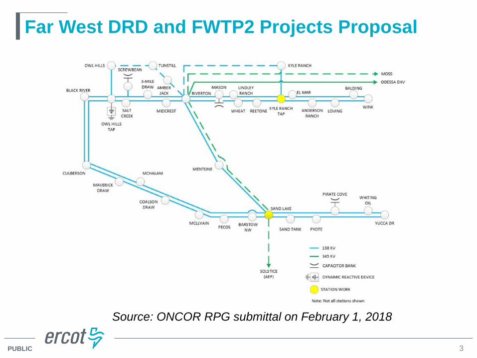
Far West DRD and FWTP2 Projects Proposal
3
Source: ONCOR RPG submittal on February 1, 2018

PUBLIC
Culberson Loop Load Growth
4
• Existing and confirmed load requests of 880 MW by 2019
• Existing, confirmed, and conceptual load of 1347 MW by 2023

PUBLIC
Project Needs
Scenario Load (MW) Transmission
Upgrades
Culberson Load Serving Capability
NERC P1, P7 NERC P6
1.880
(2019 Summer Peak)None Pre-contingency Voltage Collapse
2. 880
(2019 Summer Peak)FWTP*
Voltage ViolationVoltage Collapse
Voltage ViolationVoltage Collapse
5
Steady State Voltage Stability Assessment for the Base Case Condition
*The Far West Texas Project (FWTP) endorsed by ERCOT Board of Directors in June, 2017.
PUBLIC
Options Considerations
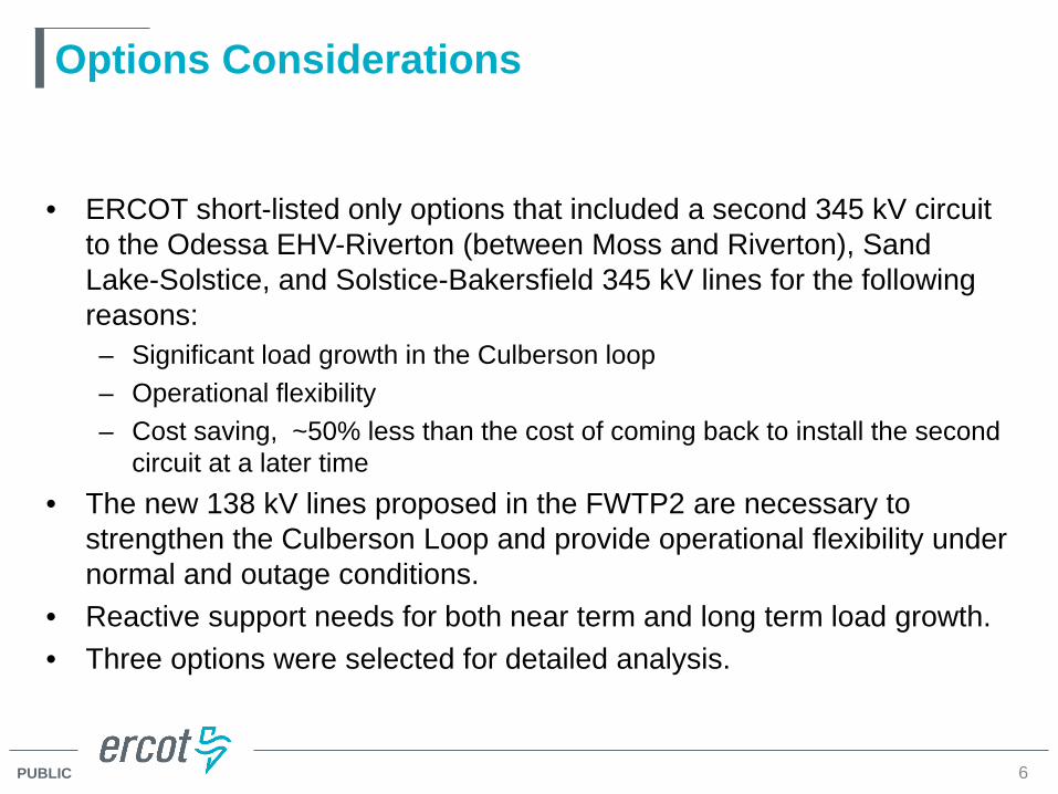
• ERCOT short-listed only options that included a second 345 kV circuit to the Odessa EHV-Riverton (between Moss and Riverton), Sand Lake-Solstice, and Solstice-Bakersfield 345 kV lines for the following reasons:– Significant load growth in the Culberson loop– Operational flexibility– Cost saving, ~50% less than the cost of coming back to install the second
circuit at a later time• The new 138 kV lines proposed in the FWTP2 are necessary to
strengthen the Culberson Loop and provide operational flexibility under normal and outage conditions.
• Reactive support needs for both near term and long term load growth.• Three options were selected for detailed analysis.
6
PUBLIC 7
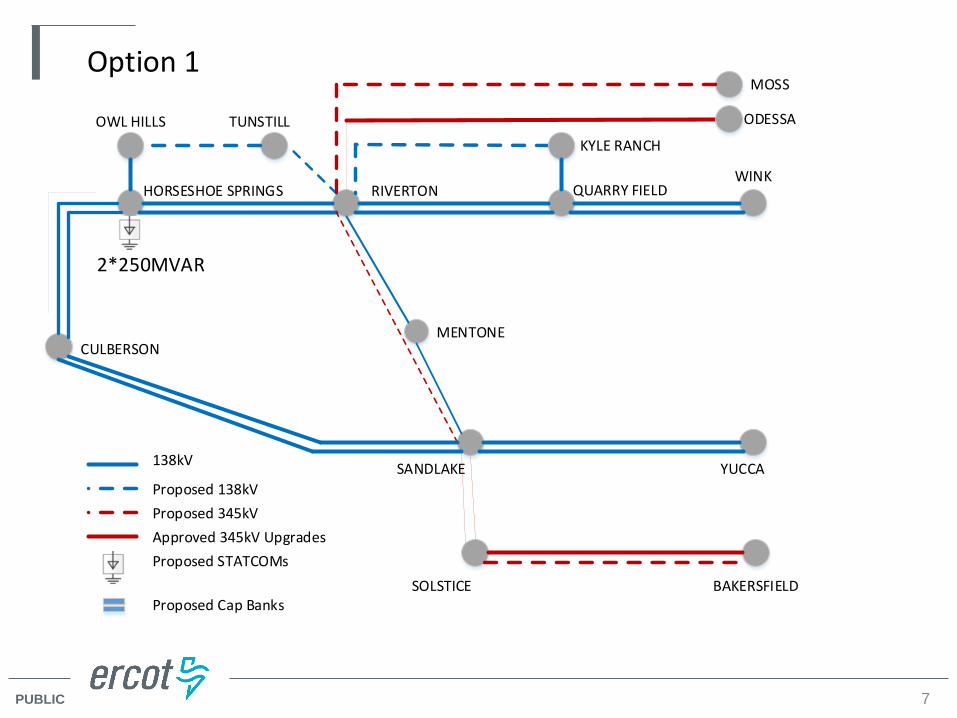
WINKQUARRY FIELDRIVERTONHORSESHOE SPRINGS
CULBERSON
YUCCASANDLAKE
MENTONE
SOLSTICE BAKERSFIELD
ODESSA
MOSS
138kV
Proposed 138kVProposed 345kV
Proposed STATCOMsApproved 345kV Upgrades
Option 1
2*250MVAR
Proposed Cap Banks
TUNSTILLKYLE RANCH
OWL HILLS
PUBLIC 8
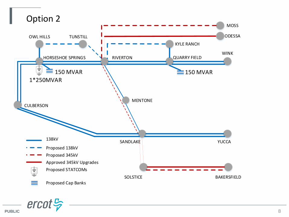
WINKQUARRY FIELDRIVERTONHORSESHOE SPRINGS
CULBERSON
YUCCASANDLAKE
MENTONE
SOLSTICE BAKERSFIELD
ODESSA
MOSS
138kV
Proposed 138kVProposed 345kV
Proposed STATCOMsApproved 345kV Upgrades
Option 2
1*250MVAR150 MVAR
Proposed Cap Banks
TUNSTILLKYLE RANCH
150 MVAR
OWL HILLS
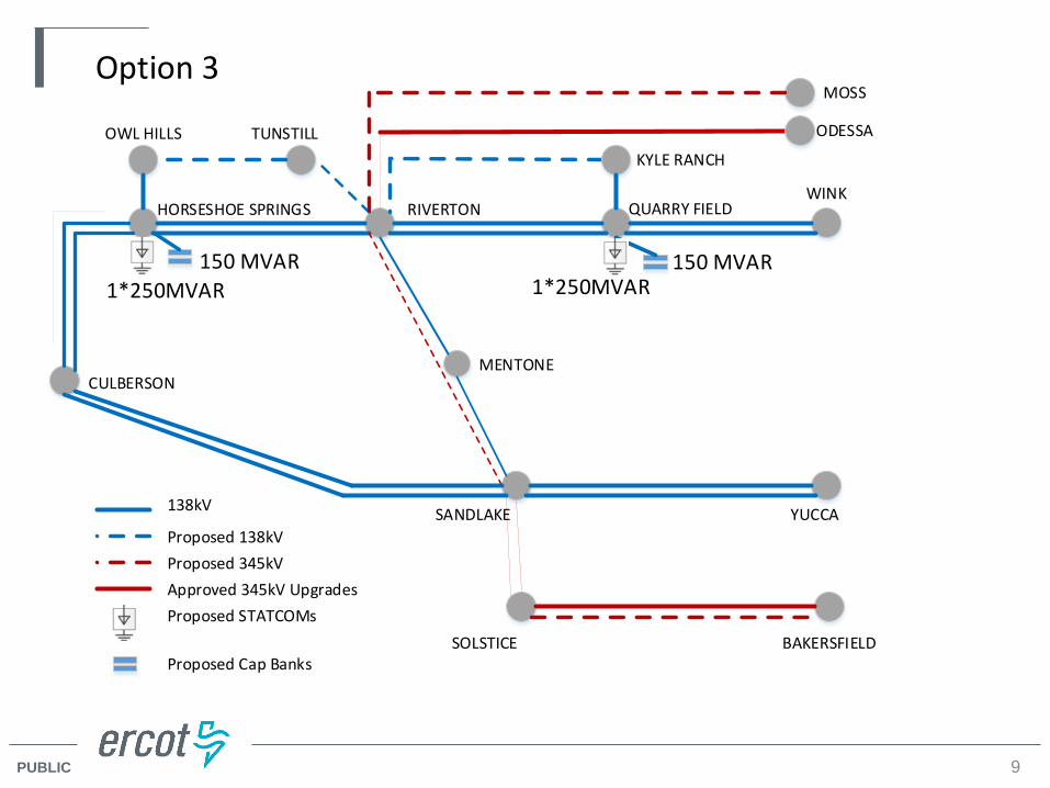
PUBLIC 9
WINKQUARRY FIELDRIVERTONHORSESHOE SPRINGS
CULBERSON
YUCCASANDLAKE
MENTONE
SOLSTICE BAKERSFIELD
ODESSA
MOSS
138kV
Proposed 138kVProposed 345kV
Proposed STATCOMsApproved 345kV Upgrades
Option 3
1*250MVAR150 MVAR
Proposed Cap Banks
TUNSTILLKYLE RANCH
150 MVAR1*250MVAR
OWL HILLS

PUBLIC
Comparison of Project Options
10
Note:(1). Dynamic stability was conducted at the Culberson load level identified in the PV voltage collapse results. (2). Assuming reactive devices will be in service before new transmission lines.(3). Oncor indicated that the reactive devices identified to be located at Quarry Field 138 kV Switch Station may not be in service by summer 2019. ERCOT performed a PV analysis considering only the reactive devices located at Horseshoe Springs from Option 3. The results showed that without the Quarry Field reactive devices in service, Option 3 would have a load serving capability of 721 MW..
Culberson Loop Load Served (MW)Description Option 1 Option 2 Option 3
PV Voltage Collapse Results (NERC P1, P6, P7, ERCOT Events)
1608 1568 1688
PV Voltage Collapse Results (without PBSES Units) (NERC P1, P6, P7, ERCOT Events)
1508 1468 1648
Dynamic Stability Result (without PBSES Units) (NERC P1, P6, P7, ERCOT Events)(1)
Acceptable Acceptable Acceptable
Estimated Capital Cost ($M) 300 292.5 327.5
PV Voltage Collapse Results (reactive devices only(2)
(NERC P1, P6, P7, ERCOT Events)801 821 1001
PV Voltage Collapse Results (without PBSES units) (reactive devices only(2) (NERC P1, P6, P7, ERCOT
Events)721 741 880(3)
PUBLIC
Subsynchronous Resonance (SSR) Vulnerability Assessment – Protocol Section 3.22.1.3(2)
• All three short-listed options strengthen the transmission network and increase the required transmission circuit outages to have a Generation Resource become radial to series capacitors.
• The SSR assessment results showed no SSR vulnerability for any existing Generation Resources or Generation Resources satisfying Planning Guide Section 6.9 conditions for inclusion in the planning models at the time of this study.
11
PUBLIC
Additional Economic and Steady State Analysis for Option 3
• ERCOT conducted an economic analysis to identify any potential impact on system congestion related to Option 3:– The annual production analysis showed no measurable congestion impact
on the ERCOT System with the addition of the transmission upgrades related to Option 3
• ERCOT also conducted a detail steady state analysis to identify any potential reliability issues (outside the Culberson loop) related to Option 3:– The analysis showed no additional reliability issues (thermal & voltage)
with the addition of the transmission upgrades related to Option 3
12
PUBLIC
Sensitivity Analysis – PG Section 3.1.3 (4)
• Generation Sensitivity Studies– No solar generation in the Culberson loop is assumed the most stressed system
condition considering the oil and gas industry load.– The proposed Generation Resources in the Culberson loop area are all solar
projects and will have no impact on the recommended transmission project.
• Load Scaling Impact Analysis– Because the voltage violations were observed at load serving buses inside the
Culberson loop, ERCOT assumed that the load scaling in the outside weather zones did not have a material impact on the observed need.
13

PUBLIC
ERCOT Recommendation
• Based on the review, ERCOT will recommend the Board endorse Option 3 (listed in the next slide) to address the reliability need in the study region
• Estimated Capital Cost: $327.5 million• ERCOT will recommend that the Board deems the Riverton – Sand
Lake 345 kV line, the Sand Lake – Solstice 345 kV line, and the Bakersfield – Solstice 345 kV line project critical to reliability
14

PUBLIC
ERCOT Recommendation: Option 3
• Construct a new approximately 40-mile 345 kV line on double-circuit structures with two circuits in place from Sand Lake 345 kV Switch Station to Solstice 345 kV Switch Station
• Add two new 600 MVA, 345/138 kV autotransformers at Sand Lake 345 kV Switch Station • Install a new 345 kV circuit on the planned Riverton – Sand Lake double circuit structures • Install the second 345 kV circuit on the Odessa EHV – Riverton 345 kV line double circuit structures
between Moss and Riverton (creating a Moss – Riverton 345 kV circuit) • Construct a new Quarry Field 138 kV Switch Station in the Wink – Riverton double-circuit 138 kV line • Construct a new approximately 20-mile Kyle Ranch – Riverton 138 kV line on double-circuit structures
with one circuit in place from Kyle Ranch 138 kV Substation to Riverton 138 kV Switch Station • Construct a new approximately 20-mile Owl Hills – Tunstill – Riverton 138 kV line on double circuit
structures with one circuit in place from Owl Hills 138 kV Switch Substation to Riverton 138 kV Switch Station
• Install the second 345 kV circuit on the planned Solstice 345 kV Switch Station – Bakersfield 345 kV Switch Station double circuit structures
• Install one 250 MVAR STATCOM at Horseshoe Springs 138 kV Switch Station • Install one 250 MVAR STATCOM at Quarry Field 138 kV Switch Station• Install 150 MVAR static capacitors at Horseshoe Springs 138 kV Switch Station • Install 150 MVAR static capacitors at Quarry Field 138 kV Switch Station
15

PUBLIC
ERCOT Recommendation – Option 3
16
WINK
KYLE RANCH TAP
RIVERTON
OWL HILL TAP
CULBERSON
YUCCASANDLAKE
MENTONE
SOLSTICE BAKERSFIELD
ODESSA
MOSS
138kV
Proposed 138kVProposed 345kV
Proposed STATCOMsApproved 345kV Upgrades
Option 3
1*250MVAR150 MVAR
Proposed Cap Banks
TUNSTILL KYLE RANCH
150 MVAR1*250MVAR
OWL HILL

PUBLIC
Nest Steps
• ERCOT will present the project recommendation to – TAC on May 24th
– BOD on June 12th
17

PUBLIC
Appendix
18

PUBLIC
Study Assumptions
Steady-State Study Case
o Constructed from latest 17RTP reliability case 17RTP_2020_SUM_WFW
o Study Region will consist of Far-West and West Weather Zones
o Generator additions that meet Planning Guide Section 6.9 criteria in study region at time of study will be added to the case.
o Transmission Projects expected to be in-service within the study region by 2020 at the time of the study will be added to the case
Dynamic Study Case
o Start from DWG 2020 Summer Peak Flat Start Case
o The Dynamic Study case was updated to reflect the 2019 and 2023 load projects in the Culberson loop
19

PUBLIC
Contingencies and Criteria Initial Steady-State Reliability Analysis
o Contingencies for Study Region NERC TPL-001-4 and ERCOT Planning Criteria):
• P0• P1-1, P1-2, P1-3, P1-4, • P2-1, P2-2, P2-3 (All EHV only)• P3-1, P3-2, P3-3, P3-4, G-1+P7 {G-1 worst case only}• P4-1, P4-2, P4-3, P4-4, P4-5 (All EHV only)• P5-1, P5-2, P5-3, P5-4, P5-5 (All EHV only)• P6-2: X-1 + (P1-1, P1-2, P1-3, P1-4, P7-1) {X-1 is 345 kV Auto outages}• P7-1
o Criteria: Thermal
• Monitor all transmission lines and transformers in study region (excluding GSU)
• Use Rate A for Normal Conditions• Use Rate B for Emergency Conditions
Voltages • Monitor all busses 100 kV and above• 0.95 < 1.05 Normal • 0.90 < 1.05 Emergency• Voltage deviations exceeding 8% on non-radial load busses
20