falcom a2 - xenyasup.xenya.si/sup/info/falcom/a2/manuals/a2man.pdffalcom a2 a2man.doc 08 march 1999...
TRANSCRIPT
This document is available at ftp://ftp.falcom.de/pub/a2/manuals
Funkanlagen Leipoldt, D-98704 Langewiesen, Gewerbering 6Tel: +49 3677 8042-0Fax: +49 3677 8042-215 Email: [email protected]
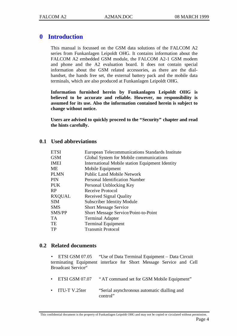
FALCOM A2(INCLUDING A2-A, A2-B, A2-1 AND EVALUATION BOARD)
User Manual / Command List
Date: 08 March 1999

FALCOM A2 A2MAN.DOC 08 MARCH 1999
This confidential document is the property of Funkanlagen Leipoldt OHG and may not be copied or circulated without permission.
Page 1
0 INTRODUCTION ...........................................................................................40.1 USED ABBREVIATIONS ............................................................................................................... 40.2 RELATED DOCUMENTS............................................................................................................... 40.3 SECURITY ................................................................................................................................. 50.4 SAFETY STANDARDS .......................................................................................................... 7
1 GSM 07.05 AND 07.07 COMMANDS ............................................................81.1 PREFACE................................................................................................................................... 81.2 COMMANDS CONCERNING MODEM HARDWARE ........................................................................... 81.2.1 AT+CGMI ............................................................................................................................... 81.2.2 AT+CGMM ............................................................................................................................. 81.2.3 AT+CGMR.............................................................................................................................. 81.2.4 AT+CGSN............................................................................................................................... 91.3 NETWORK REGISTRATION COMMANDS ....................................................................................... 91.3.1 AT+CPIN ................................................................................................................................ 91.3.2 AT+CREG............................................................................................................................. 101.3.3 AT+COPS.............................................................................................................................. 101.3.4 AT+CSQ................................................................................................................................ 111.4 CALL CONTROL COMMANDS .................................................................................................... 121.4.1 ATD; ..................................................................................................................................... 121.4.2 ATD....................................................................................................................................... 121.4.3 ATA....................................................................................................................................... 131.4.4 ATH....................................................................................................................................... 131.4.5 AT+VGR ............................................................................................................................... 131.4.6 AT+VGT ............................................................................................................................... 141.4.7 AT+VTS................................................................................................................................ 141.4.8 AT+VTD ............................................................................................................................... 141.4.9 +++........................................................................................................................................ 151.4.10 ATO....................................................................................................................................... 151.4.11 AT+CBST.............................................................................................................................. 151.4.12 Remote disconnection............................................................................................................. 161.5 CALL INFORMATION COMMANDS ............................................................................................. 161.5.1 AT+CR .................................................................................................................................. 161.5.2 AT+CRC................................................................................................................................ 161.6 CALL SETTING COMMANDS ...................................................................................................... 171.6.1 ATS0 ..................................................................................................................................... 171.6.2 AT+CCFC ............................................................................................................................. 171.6.3 AT+CCWA............................................................................................................................ 181.6.4 AT+CLIP............................................................................................................................... 191.6.5 AT+CLIR............................................................................................................................... 191.6.6 AT+COLP ............................................................................................................................. 201.7 PHONEBOOK COMMANDS......................................................................................................... 211.7.1 AT+CPBS.............................................................................................................................. 211.7.2 AT+CPBR.............................................................................................................................. 211.7.3 AT+CPBF.............................................................................................................................. 221.7.4 AT+CPBW ............................................................................................................................ 231.8 MESSAGE HANDLING COMMANDS ............................................................................................ 241.8.1 AT+CSCA ............................................................................................................................. 241.8.2 AT+CMGL ............................................................................................................................ 241.8.3 AT+CMGR............................................................................................................................ 261.8.4 AT+CMGS ............................................................................................................................ 281.8.5 AT+CMSS............................................................................................................................. 291.8.6 AT+CMGW........................................................................................................................... 301.8.7 AT+CMGD............................................................................................................................ 311.9 MESSAGE SETTING COMMANDS................................................................................................ 321.9.1 AT+CSMS............................................................................................................................. 321.9.2 AT+CPMS............................................................................................................................. 321.9.3 AT+CMGF ............................................................................................................................ 331.9.4 AT+CSMP............................................................................................................................. 341.9.5 AT+CSDH ............................................................................................................................. 34

FALCOM A2 A2MAN.DOC 08 MARCH 1999
This confidential document is the property of Funkanlagen Leipoldt OHG and may not be copied or circulated without permission.
Page 2
1.9.6 AT+CNMI ............................................................................................................................. 351.9.7 AT+CSCB ............................................................................................................................. 351.10 FUNCTIONALITY COMMANDS ................................................................................................... 361.10.1 AT+GCAP............................................................................................................................. 361.10.2 AT+CSCS.............................................................................................................................. 361.10.3 AT+CLCK............................................................................................................................. 361.10.4 AT+CPWD ............................................................................................................................ 371.10.5 AT+CFUN ............................................................................................................................. 381.10.6 AT+CPAS.............................................................................................................................. 391.11 STORING/RESTORING COMMANDS ............................................................................................ 391.11.1 AT&W................................................................................................................................... 391.11.2 AT&F .................................................................................................................................... 401.11.3 AT+CSAS.............................................................................................................................. 401.11.4 AT+CRES.............................................................................................................................. 401.12 ERROR MESSAGE HANDLING AND SURVEY ................................................................................ 411.12.1 AT +CMEE............................................................................................................................ 411.12.2 Mobile equipment error result code : +CME ERROR: xxx ...................................................... 411.12.3 Message service failure result code: +CMS ERROR :<err>.................................................... 421.12.4 AT +CEER............................................................................................................................. 451.12.5 Cause information element values from GSM recommendation 04.08 ..................................... 45
2 A2-A / A2-B....................................................................................................472.1 TECHNICAL DATA.................................................................................................................... 472.2 POSSIBLE EXTERNAL DEVICES:................................................................................................. 482.3 CONNECTORS AT THE A2......................................................................................................... 492.4 PIN-OUT OF THE A2 MODULE .................................................................................................. 502.5 SPECIAL FUNCTIONALITY PINS ................................................................................................. 502.5.1 Pin 29 on C1, Pin 3 on C2 (SOFT ON/OFF) ........................................................................... 502.5.2 Pin 26 on C1 (RSTF).............................................................................................................. 512.5.3 Pin 5 on C2 (BRSF)................................................................................................................ 512.6 FIRMWARE DOWNLOAD PROCEDURE ....................................................................................... 51
3 A2-1 MODULE..............................................................................................533.1 TECHNICAL DATA ................................................................................................................... 533.2 CONNECTORS AT THE A2-1...................................................................................................... 543.3 FUNCTIONAL DESCRIPTION ...................................................................................................... 553.3.1 Ignition line............................................................................................................................ 553.3.2 Serial handling ....................................................................................................................... 553.3.3 Reset configuration................................................................................................................. 563.3.4 Firmware update..................................................................................................................... 56
4 EVALUATION BOARD ...............................................................................574.1 TECHNICAL DATA.................................................................................................................... 574.2 CONNECTORS AND UNITS ON THE EVALUATION BOARD ............................................................. 574.3 EVALUATION BOARD AND ACCESSORIES................................................................................... 584.4 FUNCTIONAL OVERVIEW.......................................................................................................... 584.5 USER MMI DESCRIPTION......................................................................................................... 584.5.1 Make it work.......................................................................................................................... 584.5.2 Keypad overview.................................................................................................................... 594.5.3 Display overview.................................................................................................................... 594.5.4 SIM card issues ...................................................................................................................... 604.5.5 Switching ON/OFF the Phone................................................................................................. 604.5.6 Basic MMI functions.............................................................................................................. 614.5.7 Other useful Functions............................................................................................................ 624.5.7.1 Call Forwarding ....................................................................................................................................624.5.7.2 Call Barring...........................................................................................................................................624.5.8 Menu Functions...................................................................................................................... 634.5.8.1 Phone Bk (PHONE BOOK) ....................................................................................................................644.5.8.2 Text MSG (Short Message Service) .........................................................................................................684.5.8.3 CALL INFO ...........................................................................................................................................704.5.8.4 Networks................................................................................................................................................71

FALCOM A2 A2MAN.DOC 08 MARCH 1999
This confidential document is the property of Funkanlagen Leipoldt OHG and may not be copied or circulated without permission.
Page 3
4.5.8.5 Call Setup ..............................................................................................................................................714.5.8.6 Phn Setup...............................................................................................................................................724.5.9 Using the Menu key during a call............................................................................................ 744.5.9.1 Security..................................................................................................................................................744.5.9.2 In the case one call is active ...................................................................................................................744.5.9.3 In the case two calls are active ...............................................................................................................754.5.9.4 Call Waiting...........................................................................................................................................76
5 FALCOM A2 TEST SOFTWARE................................................................775.1 OVERVIEW.............................................................................................................................. 775.2 FALCOM.INI ........................................................................................................................ 775.3 FALCOM.EXE ...................................................................................................................... 775.3.1 Voice-CALL and SMS – CALL............................................................................................. 785.3.2 Options .................................................................................................................................. 795.3.3 Info ........................................................................................................................................ 795.3.4 Test software appendix........................................................................................................... 79
6 APPENDIX ....................................................................................................846.1 RECOMMENDATION FOR POWER SUPPLY LAYOUT...................................................................... 846.2 A2 PIN DESCRIPTION................................................................................................................ 84
FALCOM A2 A2MAN.DOC 08 MARCH 1999
This confidential document is the property of Funkanlagen Leipoldt OHG and may not be copied or circulated without permission.
Page 4
0 Introduction
This manual is focussed on the GSM data solutions of the FALCOM A2series from Funkanlagen Leipoldt OHG. It contains information about theFALCOM A2 embedded GSM module, the FALCOM A2-1 GSM modemand phone and the A2 evaluation board. It does not contain specialinformation about the GSM related accessories, as there are the dial-handset, the hands free set, the external battery pack and the mobile dataterminals, which are also produced at Funkanlagen Leipoldt OHG.
Information furnished herein by Funkanlagen Leipoldt OHG isbelieved to be accurate and reliable. However, no responsibility isassumed for its use. Also the information contained herein is subject tochange without notice.
Users are advised to quickly proceed to the “Security” chapter and readthe hints carefully.
0.1 Used abbreviations
ETSI European Telecommunications Standards InstituteGSM Global System for Mobile communicationsIMEI International Mobile station Equipment IdentityME Mobile EquipmentPLMN Public Land Mobile NetworkPIN Personal Identification NumberPUK Personal Unblocking KeyRP Receive ProtocolRXQUAL Received Signal QualitySIM Subscriber Identity ModuleSMS Short Message ServiceSMS/PP Short Message Service/Point-to-PointTA Terminal AdapterTE Terminal EquipmentTP Transmit Protocol
0.2 Related documents
• ETSI GSM 07.05 “Use of Data Terminal Equipment – Data Circuitterminating Equipment interface for Short Message Service and CellBroadcast Service“
• ETSI GSM 07.07 “AT command set for GSM Mobile Equipment”
• ITU-T V.25ter “Serial asynchronous automatic dialling andcontrol”
FALCOM A2 A2MAN.DOC 08 MARCH 1999
This confidential document is the property of Funkanlagen Leipoldt OHG and may not be copied or circulated without permission.
Page 5
0.3 Security
IMPORTANT FOR THE EFFICIENT AND SAFE OPERATION OFYOUR GSM MODEM READ THIS INFORMATION BEFORE USE !
Your GSM modem is one of the most exciting and innovative electronicproducts ever developed. With it you can stay in contact with your office,your home, emergency services, and others, wherever service isprovided.
GENERAL
Your modem utilises the GSM standard for cellular technology. GSM isa newer radio frequency (« RF ») technology than the current FMtechnology that has been used for radio communications for decades. TheGSM standard has been established for use in the European communityand elsewhere.Your modem is actually a low power radio transmitter and receiver. Itsends out and receives radio frequency energy. When you use yourmodem, the cellular system handling your calls controls both the radiofrequency and the power level of your cellular modem.
EXPOSURE TO RF ENERGY
There has been some public concern about possible health effects ofusing GSM modem. Although research on health effects from RF energyhas focused for many years on the current RF technology, scientists havebegun research regarding newer radio technologies, such as GSM. Afterexisting research had been reviewed, and after compliance to allapplicable safety standards had been tested, it has been concluded thatthe product is fit for use.If you are concerned about exposure to RF energy there are things youcan do to minimise exposure. Obviously, limiting the duration of yourcalls will reduce your exposure to RF energy. In addition, you can reduceRF exposure by operating your cellular modem efficiently by followingthe below guidelines.
EFFICIENT MODEM OPERATION
For your modem to operate at the lowest power level, consistent withsatisfactory call quality :If your modem has an extendible antenna, extend it fully. Some modelsallow you to place a call with the antenna retracted. However yourmodem operates more efficiently with the antenna fully extended.Do not hold the antenna when the modem is « IN USE ». Holding theantenna affects call quality and may cause the modem to operate at ahigher power level than needed.
FALCOM A2 A2MAN.DOC 08 MARCH 1999
This confidential document is the property of Funkanlagen Leipoldt OHG and may not be copied or circulated without permission.
Page 6
ANTENNA CARE AND REPLACEMENT
Do not use the modem with a damaged antenna. If a damaged antennacomes into contact with the skin, a minor burn may result. Replace adamaged antenna immediately. Consult your manual to see if you maychange the antenna yourself. If so, use only a manufacturer-approvedantenna. Otherwise, have your antenna repaired by a qualified technician.Use only the supplied or approved antenna. Unauthorised antennas,modifications or attachments could damage the modem and maycontravene local RF emission regulations or invalidate type approval.
DRIVING
Check the laws and regulations on the use of cellular devices in the areawhere you drive. Always obey them. Also, when using your modemwhile driving, please : give full attention to driving, pull off the road andpark before making or answering a call if driving conditions so require.
ELECTRONIC DEVICES
Most electronic equipment, for example in hospitals and motor vehiclesis shielded from RF energy. However RF energy may affect somemalfunctioning or improperly shielded electronic equipment.
VEHICLE ELECTRONIC EQUIPMENT
Check your vehicle manufacturer’s representative to determine if any onboard electronic equipment is adequately shielded from RF energy.
MEDICAL ELECTRONIC EQUIPMENT
Consult the manufacturer of any personal medical devices (such aspacemakers, hearing aids, etc...) to determine if they are adequatelyshielded from external RF energy.Turn your modem OFF in health care facilities when any regulationsposted in the area instruct you to do so. Hospitals or health care facilitiesmay be using RF monitoring equipment.
AIRCRAFT
Turn your modem OFF before boarding any aircraft.Use it on the ground only with crew permission.Do not use in the air.To prevent possible interference with aircraft systems, Federal AviationAdministration (FAA) regulations require you to have permission from acrew member to use your modem while the plane is on the ground. Toprevent interference with cellular systems, local RF regulations prohibitusing your modem whilst airborne.

FALCOM A2 A2MAN.DOC 08 MARCH 1999
This confidential document is the property of Funkanlagen Leipoldt OHG and may not be copied or circulated without permission.
Page 7
CHILDREN
Do not allow children to play with your modem. It is not a toy. Childrencould hurt themselves or others (by poking themselves or others in theeye with the antenna, for example). Children could damage the modem,or make calls that increase your modem bills.
BLASTING AREAS
To avoid interfering with blasting operations, turn your unit OFF whenin a « blasting area » or in areas posted : « turn off two-way radio ».Construction crew often use remote control RF devices to set offexplosives.
POTENTIALLY EXPLOSIVE ATMOSPHERES
Turn your modem OFF when in any area with a potentially explosiveatmosphere. It is rare, but your modem or its accessories could generatesparks. Sparks in such areas could cause an explosion or fire resulting inbodily injury or even death.Areas with a potentially explosive atmosphere are often, but not always,clearly marked. They include fuelling areas such as petrol stations ;below decks on boats ; fuel or chemical transfer or storage facilities ; andareas where the air contains chemicals or particles, such as grain, dust, ormetal powders.Do not transport or store flammable gas, liquid, or explosives, in thecompartment of your vehicle which contains your modem or accessories.Before using your modem in a vehicle powered by liquefied petroleumgas (such as propane or butane) ensure that the vehicle complies with therelevant fire and safety regulations of the country in which the vehicle isto be used.
0.4 SAFETY STANDARDS
THIS CELLULAR MODEM COMPLIES WITH ALL APPLICABLERF SAFETY STANDARDS.
This cellular modem meets the standards and recommendations for theprotection of public exposure to RF electromagnetic energy establishedby governmental bodies and other qualified organisations, such as thefollowing :Directives of the European Community, Directorate General V in Mattersof Radio Frequency Electromagnetic Energy.
FALCOM A2 A2MAN.DOC 08 MARCH 1999
This confidential document is the property of Funkanlagen Leipoldt OHG and may not be copied or circulated without permission.
Page 8
1 GSM 07.05 and 07.07 commands
1.1 Preface
In the following the <err> parameter is sometimes shown. This parameterand its possible values are described in chapter “ Error message handlingand survey”.
1.2 Commands concerning modem hardware
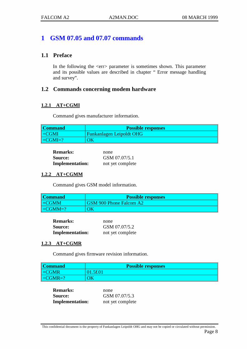
1.2.1 AT+CGMI
Command gives manufacturer information.
Command Possible responses+CGMI Funkanlagen Leipoldt OHG+CGMI=? OK
Remarks: noneSource: GSM 07.07/5.1Implementation: not yet complete
1.2.2 AT+CGMM
Command gives GSM model information.
Command Possible responses+CGMM GSM 900 Phone Falcom A2+CGMM=? OK
Remarks: noneSource: GSM 07.07/5.2Implementation: not yet complete
1.2.3 AT+CGMR
Command gives firmware revision information.
Command Possible responses+CGMR 01.5f.01+CGMR=? OK
Remarks: noneSource: GSM 07.07/5.3Implementation: not yet complete
FALCOM A2 A2MAN.DOC 08 MARCH 1999
This confidential document is the property of Funkanlagen Leipoldt OHG and may not be copied or circulated without permission.
Page 9
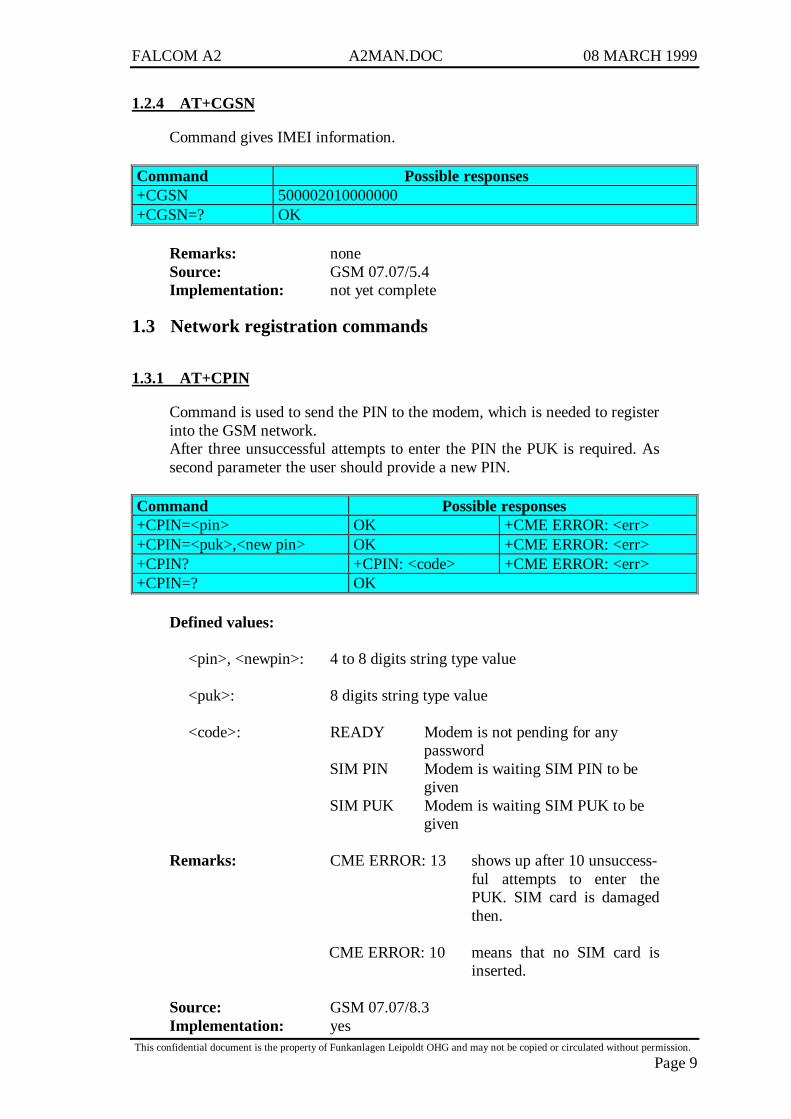
1.2.4 AT+CGSN
Command gives IMEI information.
Command Possible responses+CGSN 500002010000000+CGSN=? OK
Remarks: noneSource: GSM 07.07/5.4Implementation: not yet complete
1.3 Network registration commands
1.3.1 AT+CPIN
Command is used to send the PIN to the modem, which is needed to registerinto the GSM network.After three unsuccessful attempts to enter the PIN the PUK is required. Assecond parameter the user should provide a new PIN.
Command Possible responses+CPIN=<pin> OK +CME ERROR: <err>+CPIN=<puk>,<new pin> OK +CME ERROR: <err>+CPIN? +CPIN: <code> +CME ERROR: <err>+CPIN=? OK
Defined values:
<pin>, <newpin>: 4 to 8 digits string type value
<puk>: 8 digits string type value
<code>: READY Modem is not pending for anypassword
SIM PIN Modem is waiting SIM PIN to begiven
SIM PUK Modem is waiting SIM PUK to begiven
Remarks: CME ERROR: 13 shows up after 10 unsuccess-ful attempts to enter thePUK. SIM card is damagedthen.
CME ERROR: 10 means that no SIM card isinserted.
Source: GSM 07.07/8.3Implementation: yes
FALCOM A2 A2MAN.DOC 08 MARCH 1999
This confidential document is the property of Funkanlagen Leipoldt OHG and may not be copied or circulated without permission.
Page 10
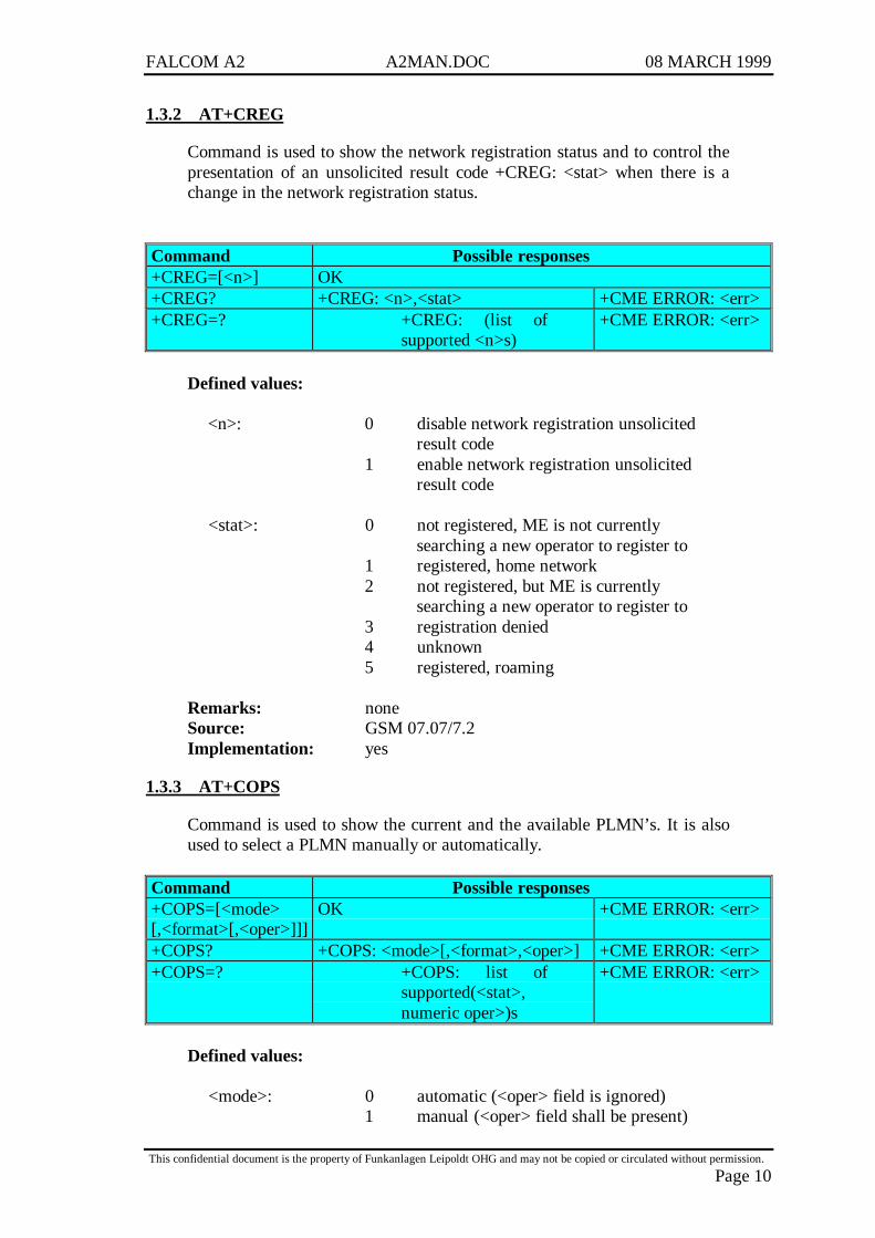
1.3.2 AT+CREG
Command is used to show the network registration status and to control thepresentation of an unsolicited result code +CREG: <stat> when there is achange in the network registration status.
Command Possible responses+CREG=[<n>] OK+CREG? +CREG: <n>,<stat> +CME ERROR: <err>+CREG=? +CREG: (list of
supported <n>s)+CME ERROR: <err>
Defined values:
<n>: 0 disable network registration unsolicitedresult code
1 enable network registration unsolicitedresult code
<stat>: 0 not registered, ME is not currentlysearching a new operator to register to
1 registered, home network2 not registered, but ME is currently
searching a new operator to register to3 registration denied4 unknown5 registered, roaming
Remarks: noneSource: GSM 07.07/7.2Implementation: yes
1.3.3 AT+COPS
Command is used to show the current and the available PLMN’s. It is alsoused to select a PLMN manually or automatically.
Command Possible responses+COPS=[<mode>[,<format>[,<oper>]]]
OK +CME ERROR: <err>
+COPS? +COPS: <mode>[,<format>,<oper>] +CME ERROR: <err>+COPS=? +COPS: list of
supported(<stat>,numeric oper>)s
+CME ERROR: <err>
Defined values:
<mode>: 0 automatic (<oper> field is ignored)1 manual (<oper> field shall be present)
FALCOM A2 A2MAN.DOC 08 MARCH 1999
This confidential document is the property of Funkanlagen Leipoldt OHG and may not be copied or circulated without permission.
Page 11
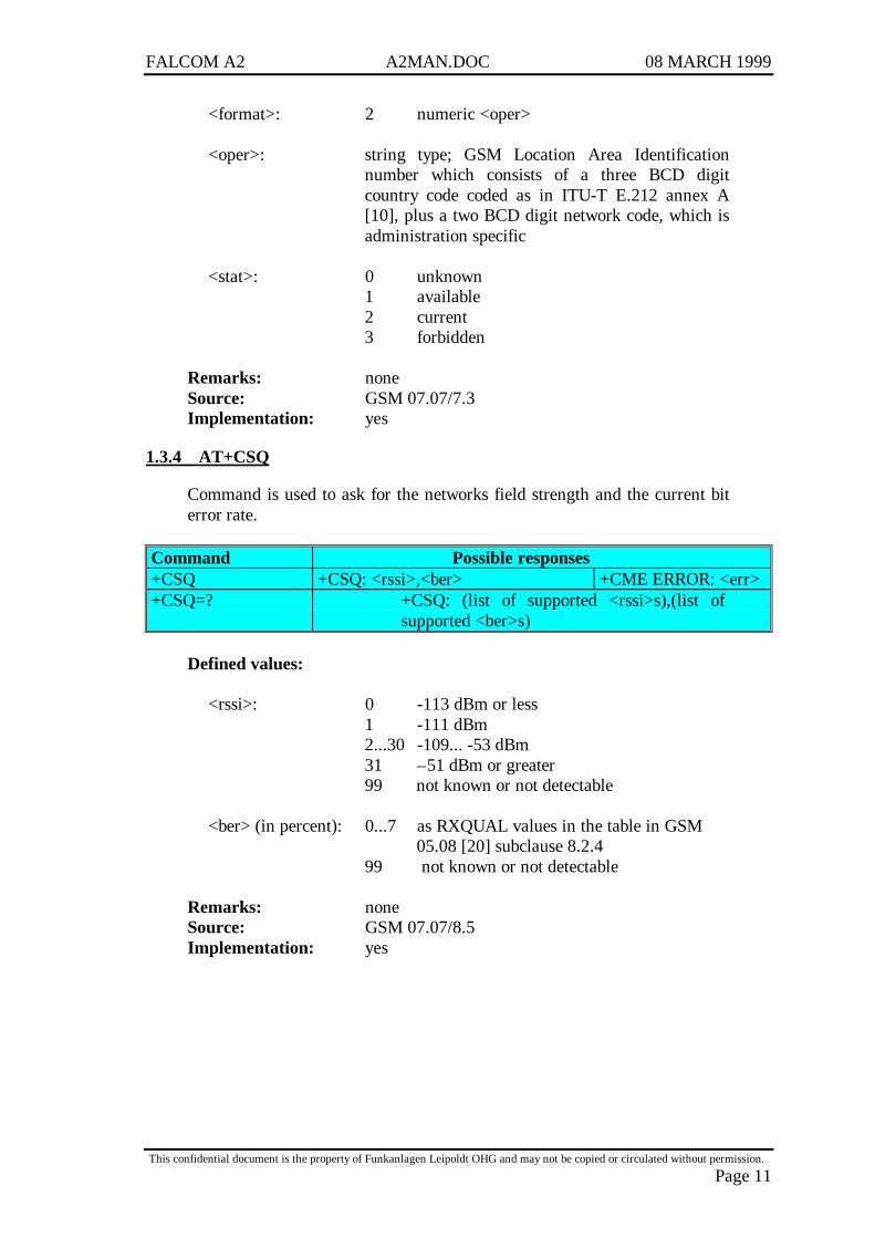
<format>: 2 numeric <oper>
<oper>: string type; GSM Location Area Identificationnumber which consists of a three BCD digitcountry code coded as in ITU-T E.212 annex A[10], plus a two BCD digit network code, which isadministration specific
<stat>: 0 unknown1 available2 current3 forbidden
Remarks: noneSource: GSM 07.07/7.3Implementation: yes
1.3.4 AT+CSQ
Command is used to ask for the networks field strength and the current biterror rate.
Command Possible responses+CSQ +CSQ: <rssi>,<ber> +CME ERROR: <err>+CSQ=? +CSQ: (list of supported <rssi>s),(list of
supported <ber>s)
Defined values:
<rssi>: 0 -113 dBm or less1 -111 dBm2...30 -109... -53 dBm31 –51 dBm or greater99 not known or not detectable
<ber> (in percent): 0...7 as RXQUAL values in the table in GSM05.08 [20] subclause 8.2.4
99 not known or not detectable
Remarks: noneSource: GSM 07.07/8.5Implementation: yes

FALCOM A2 A2MAN.DOC 08 MARCH 1999
This confidential document is the property of Funkanlagen Leipoldt OHG and may not be copied or circulated without permission.
Page 12
1.4 Call control commands
1.4.1 ATD;
Command is used to establish a voice call, if the semicolon at the end of thenumber is applied.
Command Possible responsesATD<number>; OK If call is established
BUSY If called party is in another callNO ANSWER If called party does not accept a callNO CARRIER If there are problems to establish a call
Defined values:
<number>: telephone number to dial.
Remarks: In case of international number, the localinternational prefix (usually 00) could be replacedby the '+' character.For phonebook dialling please see phonebookcommands section.
Source: GSM 07.07/V.25ter/6.3.1Implementation: yes
1.4.2 ATD
Command is used to establish a data call.
Command Possible responsesATD<number> CONNECT<speed> If call is established
BUSY If called party is in another callNO ANSWER If called party does not accept a callNO CARRIER If there are problems to establish a call
Defined values:
<speed>: link baud rate between modem and network
Remarks: Bearer type should be selected before (see at+cbst).For phonebook dialling please see phonebookcommands section.
Source: GSM 07.07/V.25ter/6.3.1Implementation: yes
FALCOM A2 A2MAN.DOC 08 MARCH 1999
This confidential document is the property of Funkanlagen Leipoldt OHG and may not be copied or circulated without permission.
Page 13
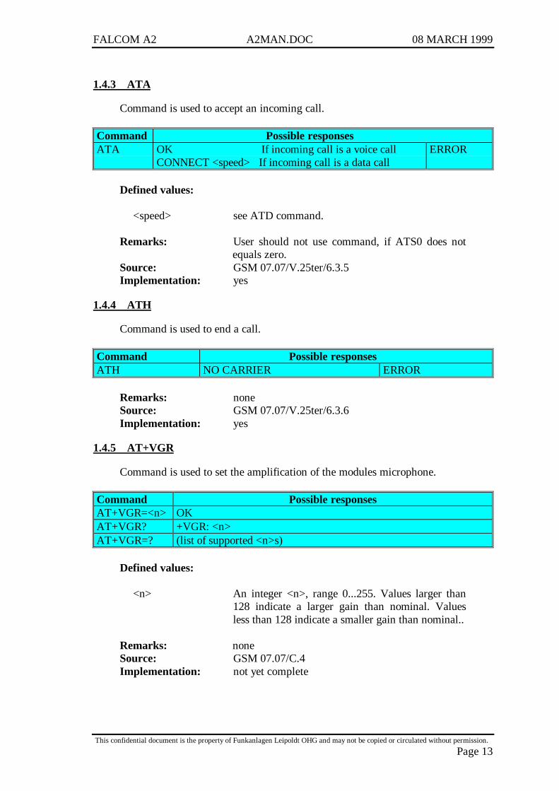
1.4.3 ATA
Command is used to accept an incoming call.
Command Possible responsesATA OK If incoming call is a voice call
CONNECT <speed> If incoming call is a data callERROR
Defined values:
<speed> see ATD command.
Remarks: User should not use command, if ATS0 does notequals zero.
Source: GSM 07.07/V.25ter/6.3.5Implementation: yes
1.4.4 ATH
Command is used to end a call.
Command Possible responsesATH NO CARRIER ERROR
Remarks: noneSource: GSM 07.07/V.25ter/6.3.6Implementation: yes
1.4.5 AT+VGR
Command is used to set the amplification of the modules microphone.
Command Possible responsesAT+VGR=<n> OKAT+VGR? +VGR: <n>AT+VGR=? (list of supported <n>s)
Defined values:
<n> An integer <n>, range 0...255. Values larger than128 indicate a larger gain than nominal. Valuesless than 128 indicate a smaller gain than nominal..
Remarks: noneSource: GSM 07.07/C.4Implementation: not yet complete
FALCOM A2 A2MAN.DOC 08 MARCH 1999
This confidential document is the property of Funkanlagen Leipoldt OHG and may not be copied or circulated without permission.
Page 14
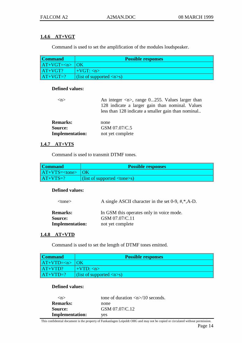
1.4.6 AT+VGT
Command is used to set the amplification of the modules loudspeaker.
Command Possible responsesAT+VGT=<n> OKAT+VGT? +VGT: <n>AT+VGT=? (list of supported <n>s)
Defined values:
<n> An integer <n>, range 0...255. Values larger than128 indicate a larger gain than nominal. Valuesless than 128 indicate a smaller gain than nominal..
Remarks: noneSource: GSM 07.07/C.5Implementation: not yet complete
1.4.7 AT+VTS
Command is used to transmit DTMF tones.
Command Possible responsesAT+VTS=<tone> OKAT+VTS=? (list of supported <tone>s)
Defined values:
<tone> A single ASCII character in the set 0-9, #,*,A-D.
Remarks: In GSM this operates only in voice mode.Source: GSM 07.07/C.11Implementation: not yet complete
1.4.8 AT+VTD
Command is used to set the length of DTMF tones emitted.
Command Possible responsesAT+VTD=<n> OKAT+VTD? +VTD: <n>AT+VTD=? (list of supported <n>s)
Defined values:
<n> tone of duration <n>/10 seconds.Remarks: noneSource: GSM 07.07/C.12Implementation: yes

FALCOM A2 A2MAN.DOC 08 MARCH 1999
This confidential document is the property of Funkanlagen Leipoldt OHG and may not be copied or circulated without permission.
Page 15
1.4.9 +++
Sequence is used to switch from on-line data mode to on-line commandmode while in a data call.
Command Possible responses+++ OK
Remarks: No <CR> is needed after the sequence.Source: Manufacturer definedImplementation: yes
1.4.10 ATO
Command is used to switch back from on-line command mode to on-linecommand data while in a data call.
Command Possible responsesATO CONNECT <speed> ERROR
Remarks: noneSource: GSM 07.07/V.25ter/6.3.7Implementation: yes
1.4.11 AT+CBST
Command is used to select the bearer service type and the transparent ornon-transparent mode for a data connection.
Command Possible responses+CBST=[<speed>,0,[,<ce>]] OKAT+CBST? +CBST=<speed>,0,<ce>AT+CBST=? +CBST: (list of supported <speed>s),0,(list of
supported <ce>s)
Defined values:
<speed>: 0 autobauding (automatic selection of thespeed)
1 300 bps (V.21)2 1200 bps (V.22)4 2400 bps (V.22bis)6 4800 bps (V.32)7 9600 bps (V.32)65 300 bps (V.110)66 1200 bps (V.110)68 2400 bps (V.110)70 4800 bps (V.110)71 9600 bps (V.110)
FALCOM A2 A2MAN.DOC 08 MARCH 1999
This confidential document is the property of Funkanlagen Leipoldt OHG and may not be copied or circulated without permission.
Page 16
<ce>: 0 transparent1 non-transparent
Remarks: noneSource: GSM 07.07/6.7Implementation: not yet complete
1.4.12 Remote disconnection
When the called party has ended a call the modem shows the final resultcode NO CARRIER.
1.5 Call information commands
1.5.1 AT+CR
Command controls whether or not intermediate result code +CR: <serv> isreturned from the modem during connect negotiation of a data call.
Command Possible responses+CR=[<mode>] OKAT+CR? +CR=<mode>AT+CR=? +CR: (list of <modes>s)
Defined values:
<mode>: 0 disables reporting1 enables reporting
<serv>: ASYNC asynchronous transparentREL ASYNC asynchronous non-transparent
Remarks: noneSource: GSM 07.07/6.9Implementation: yes
1.5.2 AT+CRC
Command controls whether or not the normal RING message of anincoming call is replaced by an extended call indication using unsolicitedresult code +CRING: <type>.
Command Possible responses+CRC=[<mode>] OKAT+CR? +CR=<mode>AT+CR=? +CR: (list of <modes>s)
FALCOM A2 A2MAN.DOC 08 MARCH 1999
This confidential document is the property of Funkanlagen Leipoldt OHG and may not be copied or circulated without permission.
Page 17
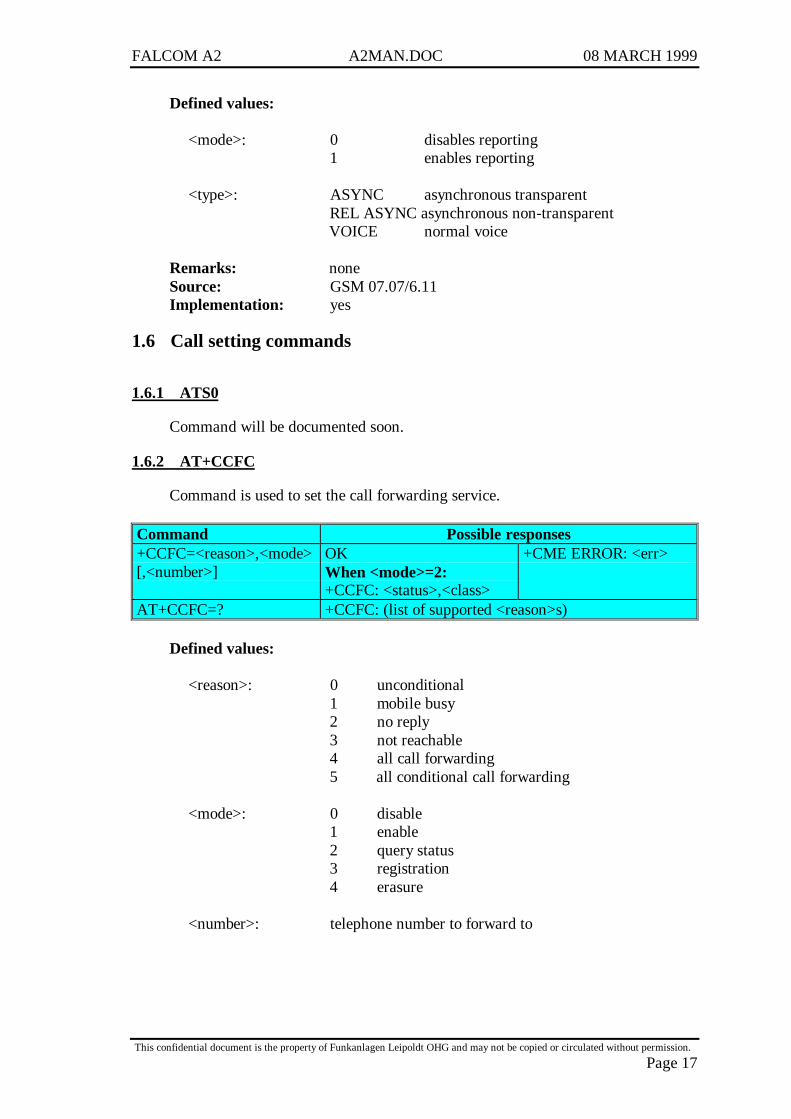
Defined values:
<mode>: 0 disables reporting1 enables reporting
<type>: ASYNC asynchronous transparentREL ASYNC asynchronous non-transparentVOICE normal voice
Remarks: noneSource: GSM 07.07/6.11Implementation: yes
1.6 Call setting commands
1.6.1 ATS0
Command will be documented soon.
1.6.2 AT+CCFC
Command is used to set the call forwarding service.
Command Possible responses+CCFC=<reason>,<mode>[,<number>]
OKWhen <mode>=2:+CCFC: <status>,<class>
+CME ERROR: <err>
AT+CCFC=? +CCFC: (list of supported <reason>s)
Defined values:
<reason>: 0 unconditional1 mobile busy2 no reply3 not reachable4 all call forwarding5 all conditional call forwarding
<mode>: 0 disable1 enable2 query status3 registration4 erasure
<number>: telephone number to forward to
FALCOM A2 A2MAN.DOC 08 MARCH 1999
This confidential document is the property of Funkanlagen Leipoldt OHG and may not be copied or circulated without permission.
Page 18
<class> is a sum of integers each representing a class ofinformation (default 7 equals to all classes):
1 voice2 data4 fax
<status>: 0 not active1 active
Remarks: noneSource: GSM 07.07/7.10Implementation: not yet complete
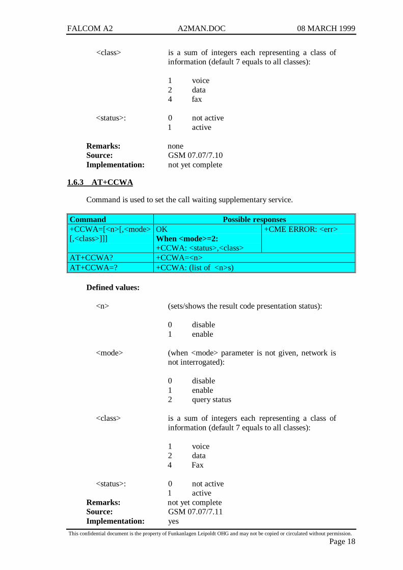
1.6.3 AT+CCWA
Command is used to set the call waiting supplementary service.
Command Possible responses+CCWA=[<n>[,<mode>[,<class>]]]
OKWhen <mode>=2:+CCWA: <status>,<class>
+CME ERROR: <err>
AT+CCWA? +CCWA=<n>AT+CCWA=? +CCWA: (list of <n>s)
Defined values:
<n> (sets/shows the result code presentation status):
0 disable1 enable
<mode> (when <mode> parameter is not given, network isnot interrogated):
0 disable1 enable2 query status
<class> is a sum of integers each representing a class ofinformation (default 7 equals to all classes):
1 voice2 data4 Fax
<status>: 0 not active1 active
Remarks: not yet completeSource: GSM 07.07/7.11Implementation: yes

FALCOM A2 A2MAN.DOC 08 MARCH 1999
This confidential document is the property of Funkanlagen Leipoldt OHG and may not be copied or circulated without permission.
Page 19
1.6.4 AT+CLIP
Command is used to set and request the status of the calling lineidentification presentation service. Depending on the setting the number ofthe calling party will be shown as result code +CLIP: <number>,<type> onincoming calls (after every RING).
Command Possible responses+CLIP=[<n>] OKAT+CLIP? +CLIP=<n>,<m>AT+CLIP=? +CLIP: (list of supported <n>s)
Defined values:
<n> (parameter sets/shows the result code presentationstatus):
0 disable1 enable
<m> (parameter shows the subscriber CLIP servicestatus in the network):
0 CLIP not provisioned1 CLIP provisioned2 unknown (e.g. no network, etc.)
<number>: string type phone number of format specified by<type>.
<type>: type of address octet in integer format.
Remarks: noneSource: GSM 07.07/7.6Implementation: yes
1.6.5 AT+CLIR
Command is used to set and request the status of the calling lineidentification restriction service. Depending on the setting the own numberis presented to the called party or not.
Command Possible responses+CLIR=[<n>] OKAT+CLIR? +CLIR=<n>,<m>AT+CLIR=? +CLIR: (list of supported <n>s)
FALCOM A2 A2MAN.DOC 08 MARCH 1999
This confidential document is the property of Funkanlagen Leipoldt OHG and may not be copied or circulated without permission.
Page 20
Defined values:
<n> (parameter sets the adjustment for outgoing calls):
0 presentation indicator is used according tothe subscription of the CLIR service
1 CLIR invocation2 CLIR suppression
<m> (parameter shows the subscriber CLIR servicestatus in the network):
0 CLIR not provisioned1 CLIR provisioned in permanent mode2 unknown (e.g. no network, etc.)3 CLIR temporary mode presentation
restricted4 CLIR temporary mode presentation allowed
Remarks: noneSource: GSM 07.07/7.7Implementation: yes
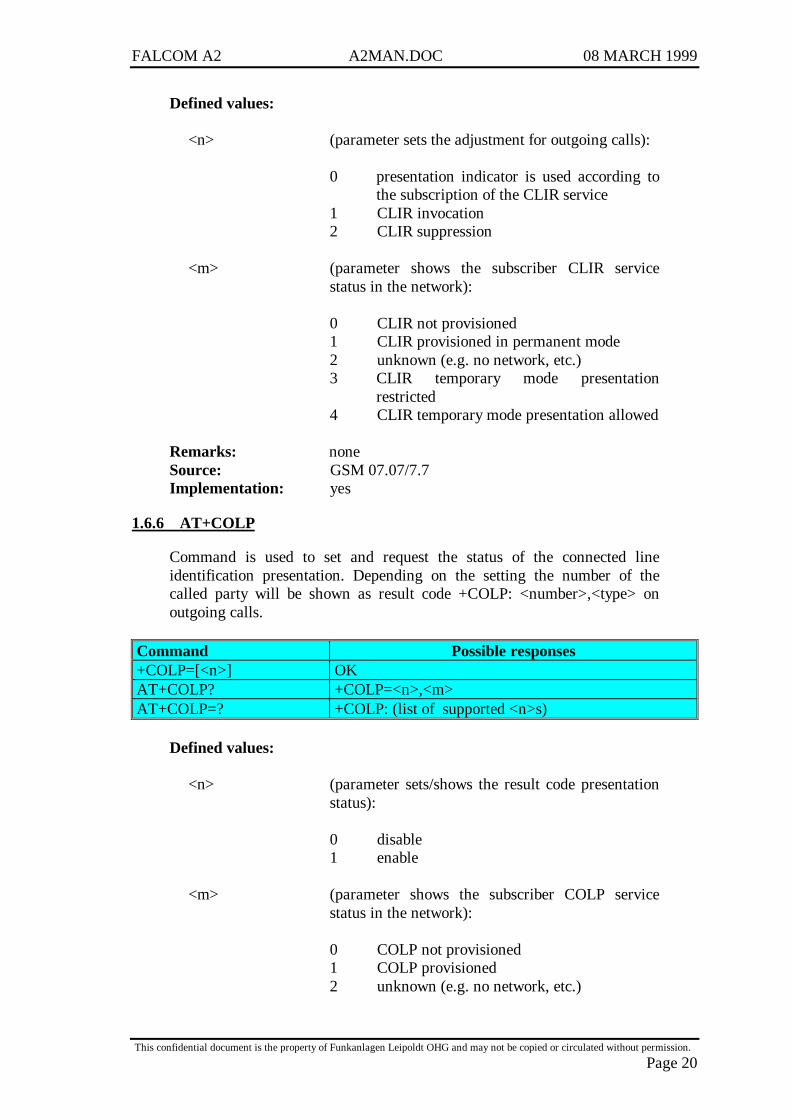
1.6.6 AT+COLP
Command is used to set and request the status of the connected lineidentification presentation. Depending on the setting the number of thecalled party will be shown as result code +COLP: <number>,<type> onoutgoing calls.
Command Possible responses+COLP=[<n>] OKAT+COLP? +COLP=<n>,<m>AT+COLP=? +COLP: (list of supported <n>s)
Defined values:
<n> (parameter sets/shows the result code presentationstatus):
0 disable1 enable
<m> (parameter shows the subscriber COLP servicestatus in the network):
0 COLP not provisioned1 COLP provisioned2 unknown (e.g. no network, etc.)
FALCOM A2 A2MAN.DOC 08 MARCH 1999
This confidential document is the property of Funkanlagen Leipoldt OHG and may not be copied or circulated without permission.
Page 21
<number>: string type phone number of format specified by<type>.
<type>: type of address octet in integer format.
Remarks: not available in most networksSource: GSM 07.07/7.8Implementation: not yet complete
1.7 Phonebook commands
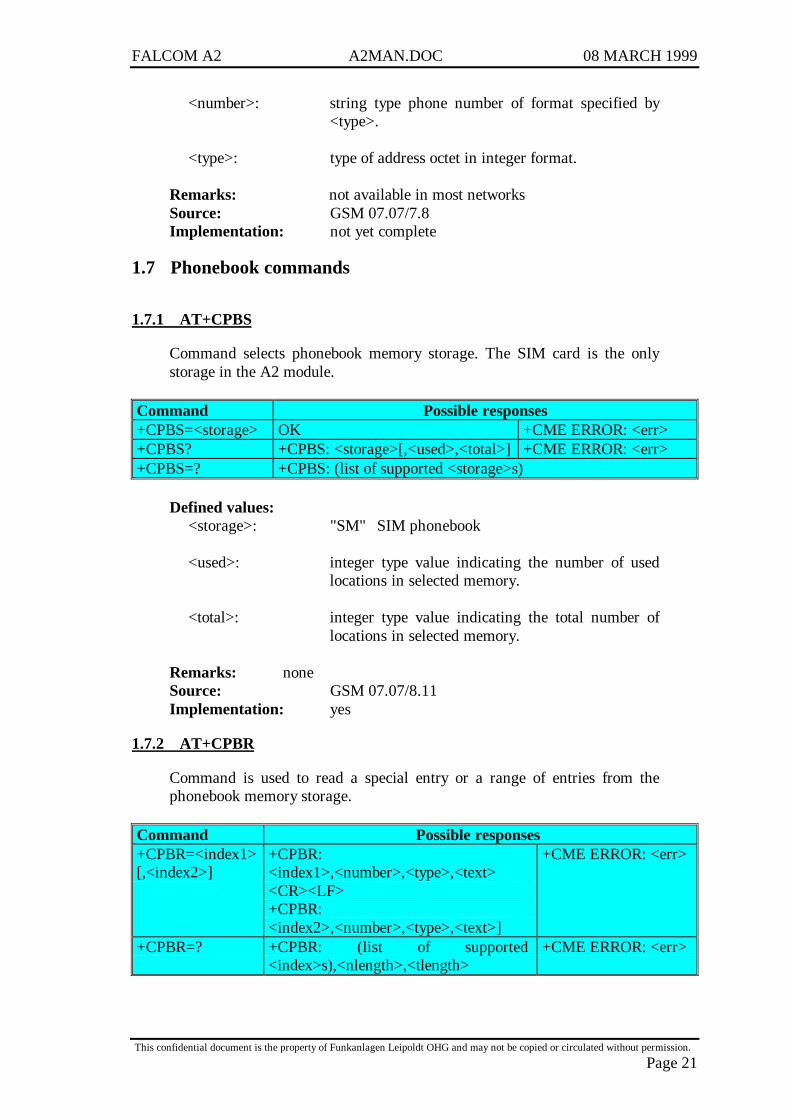
1.7.1 AT+CPBS
Command selects phonebook memory storage. The SIM card is the onlystorage in the A2 module.
Command Possible responses+CPBS=<storage> OK +CME ERROR: <err>+CPBS? +CPBS: <storage>[,<used>,<total>] +CME ERROR: <err>+CPBS=? +CPBS: (list of supported <storage>s)
Defined values:<storage>: "SM" SIM phonebook
<used>: integer type value indicating the number of usedlocations in selected memory.
<total>: integer type value indicating the total number oflocations in selected memory.
Remarks: noneSource: GSM 07.07/8.11Implementation: yes
1.7.2 AT+CPBR
Command is used to read a special entry or a range of entries from thephonebook memory storage.
Command Possible responses+CPBR=<index1>[,<index2>]
+CPBR:<index1>,<number>,<type>,<text><CR><LF>+CPBR:<index2>,<number>,<type>,<text>]
+CME ERROR: <err>
+CPBR=? +CPBR: (list of supported<index>s),<nlength>,<tlength>
+CME ERROR: <err>

FALCOM A2 A2MAN.DOC 08 MARCH 1999
This confidential document is the property of Funkanlagen Leipoldt OHG and may not be copied or circulated without permission.
Page 22
Defined values:
<index1>, <index2>, <index>: integer type values in the range oflocation numbers of phonebookmemory.
<number>: string type phone number of format<type>.
<type>: type of address octet in integerformat.
<text>: string type field of maximum length<tlength>; character set as specifiedby command Select TE CharacterSet +CSCS.
<nlength>: integer type value indicating themaximum length of field <number>.
<tlength>: integer type value indicating themaximum length of field <text>.
Remarks: noneSource: GSM 07.07/8.12Implementation: not yet complete
1.7.3 AT+CPBF
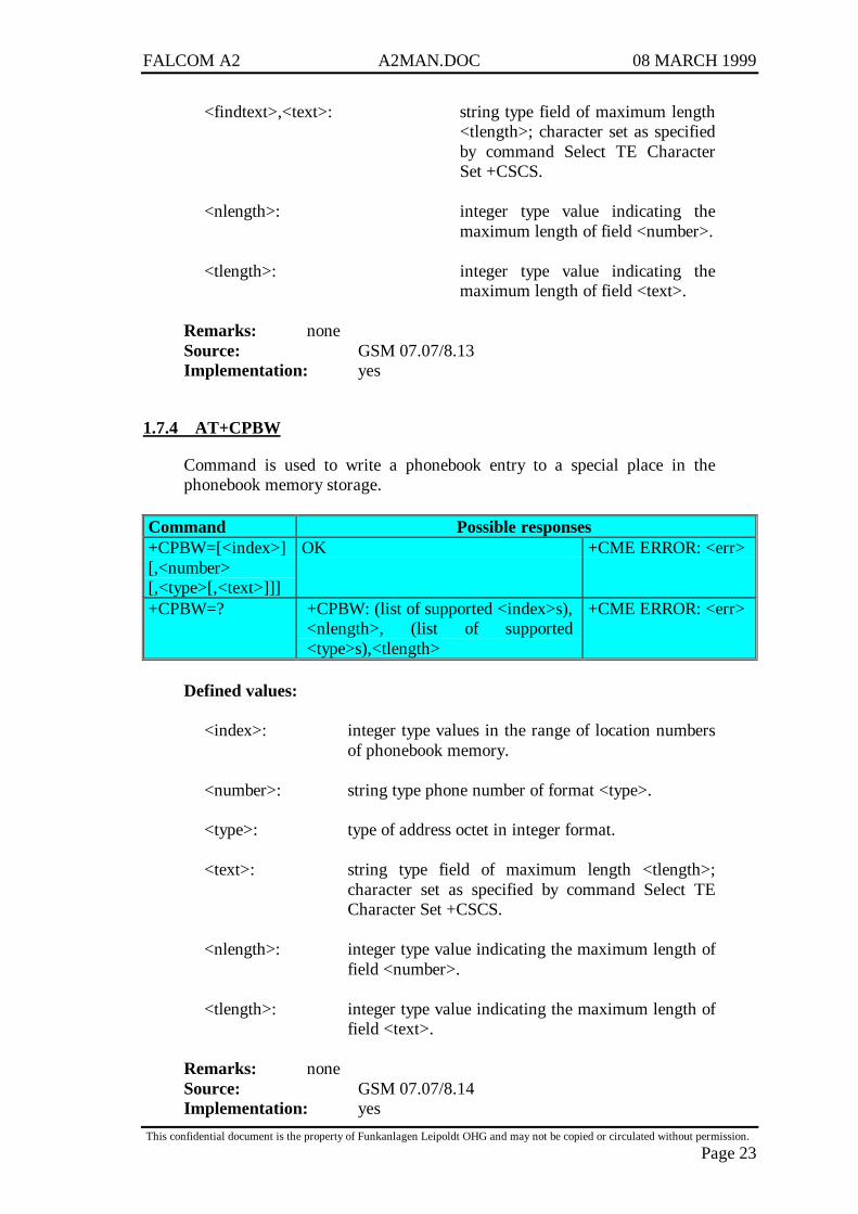
Command is used to find a phonebook entry using a search-string.
Command Possible responses+CPBF=<findtext> +CPBF:
<index1>,<number>,<type>,<text><CR><LF>+CPBF:<index2>,<number>,<type>,<text>]
+CME ERROR: <err>
+CPBF=? +CPBF: <nlength>,<tlength> +CME ERROR: <err>
Defined values:
<index1>, <index2>: integer type values in the range oflocation numbers of phonebookmemory.
<number>: string type phone number of format<type>.
<type>: type of address octet in integerformat.
FALCOM A2 A2MAN.DOC 08 MARCH 1999
This confidential document is the property of Funkanlagen Leipoldt OHG and may not be copied or circulated without permission.
Page 23
<findtext>,<text>: string type field of maximum length<tlength>; character set as specifiedby command Select TE CharacterSet +CSCS.
<nlength>: integer type value indicating themaximum length of field <number>.
<tlength>: integer type value indicating themaximum length of field <text>.
Remarks: noneSource: GSM 07.07/8.13Implementation: yes
1.7.4 AT+CPBW
Command is used to write a phonebook entry to a special place in thephonebook memory storage.
Command Possible responses+CPBW=[<index>][,<number>[,<type>[,<text>]]]
OK +CME ERROR: <err>
+CPBW=? +CPBW: (list of supported <index>s),<nlength>, (list of supported<type>s),<tlength>
+CME ERROR: <err>
Defined values:
<index>: integer type values in the range of location numbersof phonebook memory.
<number>: string type phone number of format <type>.
<type>: type of address octet in integer format.
<text>: string type field of maximum length <tlength>;character set as specified by command Select TECharacter Set +CSCS.
<nlength>: integer type value indicating the maximum length offield <number>.
<tlength>: integer type value indicating the maximum length offield <text>.
Remarks: noneSource: GSM 07.07/8.14Implementation: yes
FALCOM A2 A2MAN.DOC 08 MARCH 1999
This confidential document is the property of Funkanlagen Leipoldt OHG and may not be copied or circulated without permission.
Page 24
1.8 Message handling commands
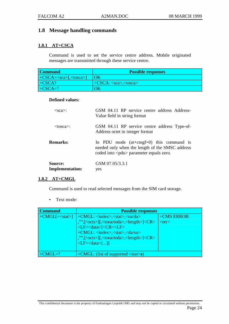
1.8.1 AT+CSCA
Command is used to set the service centre address. Mobile originatedmessages are transmitted through these service centre.
Command Possible responses+CSCA=<sca>[,<tosca>] OK+CSCA? +CSCA: <sca>,<tosca>+CSCA=? OK
Defined values:
<sca>: GSM 04.11 RP service centre address Address-Value field in string format
<tosca>: GSM 04.11 RP service centre address Type-of-Address octet in integer format
Remarks: In PDU mode (at+cmgf=0) this command isneeded only when the length of the SMSC addresscoded into <pdu> parameter equals zero.
Source: GSM 07.05/3.3.1Implementation: yes
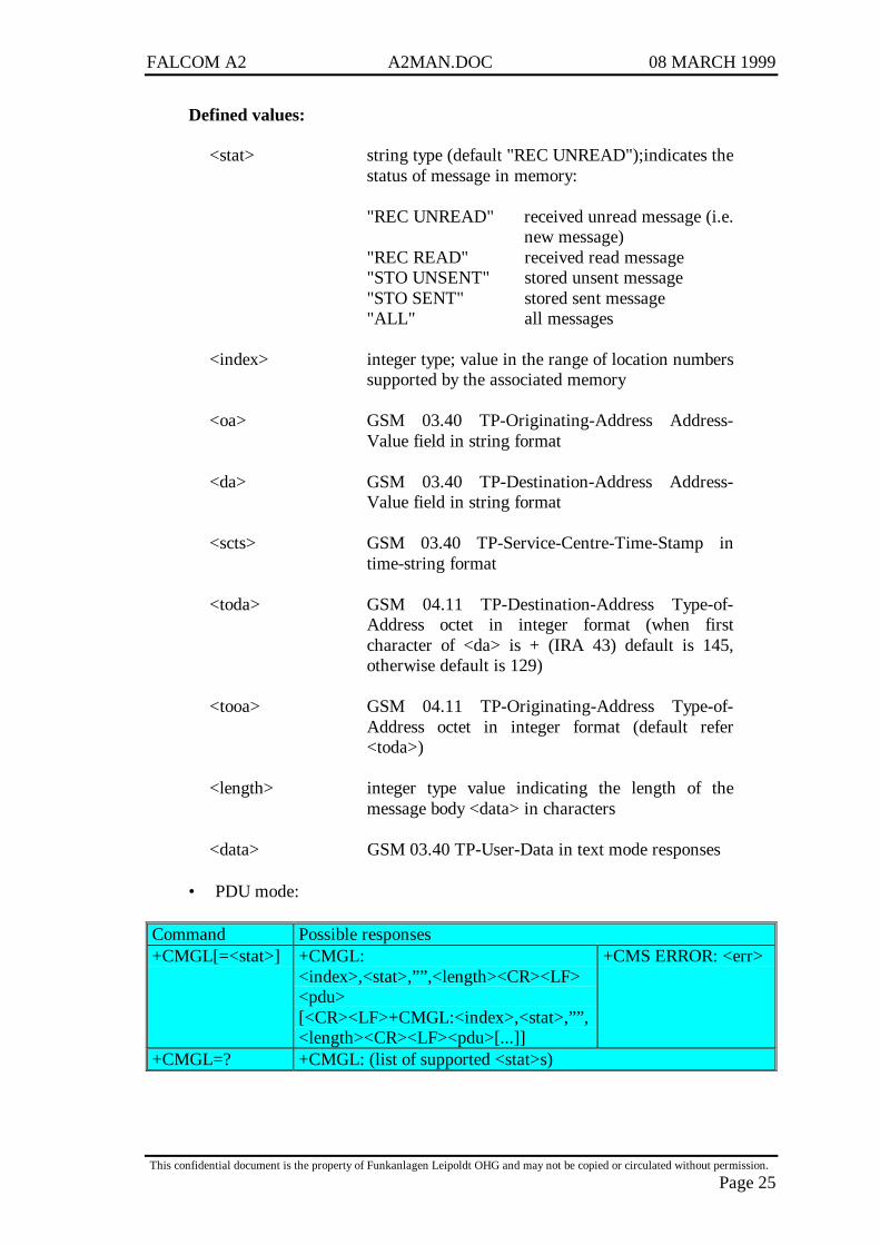
1.8.2 AT+CMGL
Command is used to read selected messages from the SIM card storage.
• Text mode:
Command Possible responses+CMGL[=<stat>] +CMGL: <index>,<stat>,<oa/da>
,””,[<scts>][,<tooa/toda>,<length>]<CR><LF><data>[<CR><LF>+CMGL: <index>,<stat>,<da/oa>,””,[<scts>][,<tooa/toda>,<length>]<CR><LF><data>[...]]
+CMS ERROR:<err>
+CMGL=? +CMGL: (list of supported <stat>s)
FALCOM A2 A2MAN.DOC 08 MARCH 1999
This confidential document is the property of Funkanlagen Leipoldt OHG and may not be copied or circulated without permission.
Page 25
Defined values:
<stat> string type (default "REC UNREAD");indicates thestatus of message in memory:
"REC UNREAD" received unread message (i.e.new message)
"REC READ" received read message"STO UNSENT" stored unsent message"STO SENT" stored sent message"ALL" all messages
<index> integer type; value in the range of location numberssupported by the associated memory
<oa> GSM 03.40 TP-Originating-Address Address-Value field in string format
<da> GSM 03.40 TP-Destination-Address Address-Value field in string format
<scts> GSM 03.40 TP-Service-Centre-Time-Stamp intime-string format
<toda> GSM 04.11 TP-Destination-Address Type-of-Address octet in integer format (when firstcharacter of <da> is + (IRA 43) default is 145,otherwise default is 129)
<tooa> GSM 04.11 TP-Originating-Address Type-of-Address octet in integer format (default refer<toda>)
<length> integer type value indicating the length of themessage body <data> in characters
<data> GSM 03.40 TP-User-Data in text mode responses
• PDU mode:
Command Possible responses+CMGL[=<stat>] +CMGL:
<index>,<stat>,””,<length><CR><LF><pdu>[<CR><LF>+CMGL:<index>,<stat>,””,<length><CR><LF><pdu>[...]]
+CMS ERROR: <err>
+CMGL=? +CMGL: (list of supported <stat>s)
FALCOM A2 A2MAN.DOC 08 MARCH 1999
This confidential document is the property of Funkanlagen Leipoldt OHG and may not be copied or circulated without permission.
Page 26
Defined values:
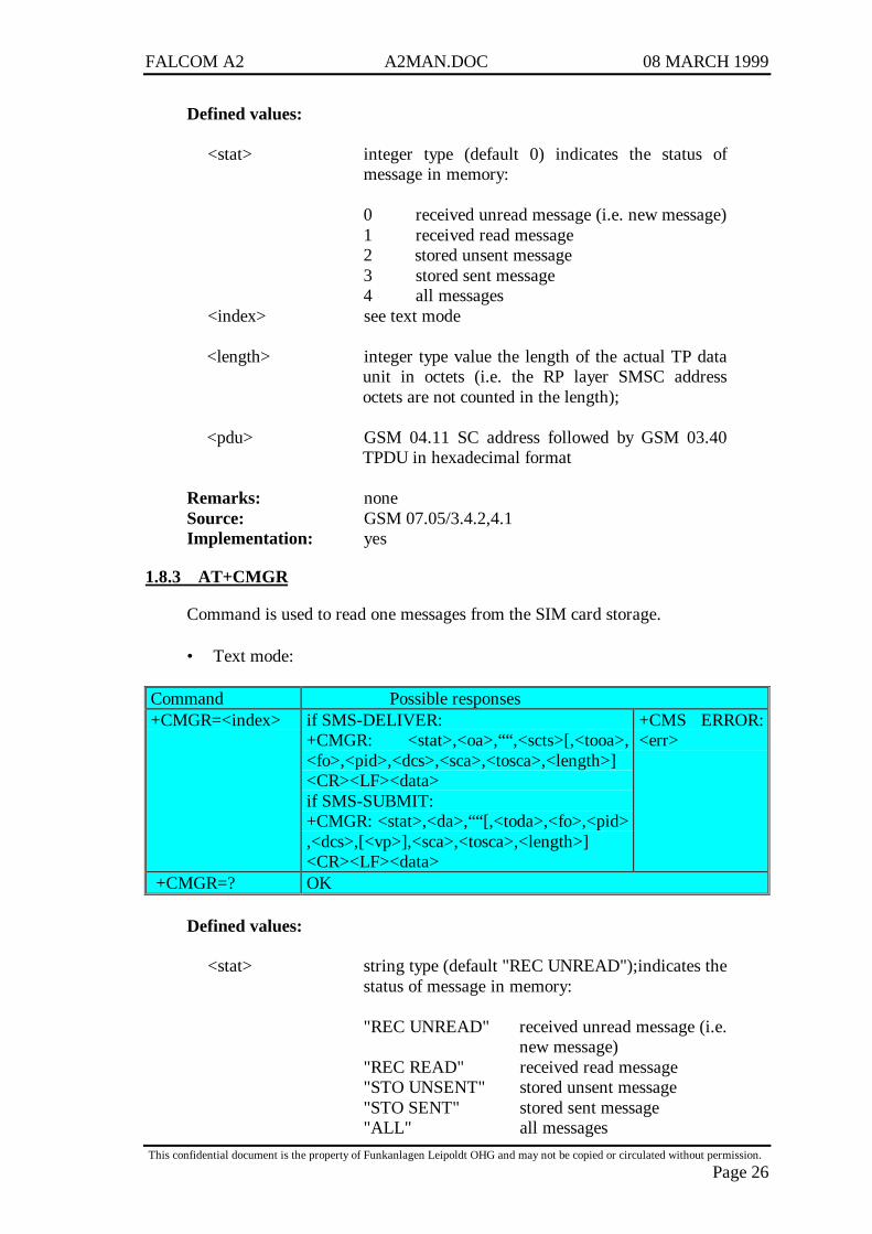
<stat> integer type (default 0) indicates the status ofmessage in memory:
0 received unread message (i.e. new message)1 received read message2 stored unsent message3 stored sent message4 all messages
<index> see text mode
<length> integer type value the length of the actual TP dataunit in octets (i.e. the RP layer SMSC addressoctets are not counted in the length);
<pdu> GSM 04.11 SC address followed by GSM 03.40TPDU in hexadecimal format
Remarks: noneSource: GSM 07.05/3.4.2,4.1Implementation: yes
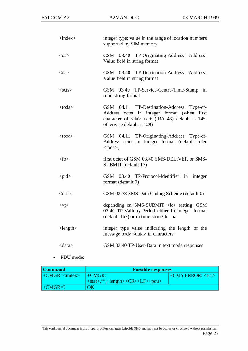
1.8.3 AT+CMGR
Command is used to read one messages from the SIM card storage.
• Text mode:
Command Possible responses+CMGR=<index> if SMS-DELIVER:
+CMGR: <stat>,<oa>,““,<scts>[,<tooa>,<fo>,<pid>,<dcs>,<sca>,<tosca>,<length>]<CR><LF><data>if SMS-SUBMIT:+CMGR: <stat>,<da>,““[,<toda>,<fo>,<pid>,<dcs>,[<vp>],<sca>,<tosca>,<length>]<CR><LF><data>
+CMS ERROR:<err>
+CMGR=? OK
Defined values:
<stat> string type (default "REC UNREAD");indicates thestatus of message in memory:
"REC UNREAD" received unread message (i.e.new message)
"REC READ" received read message"STO UNSENT" stored unsent message"STO SENT" stored sent message"ALL" all messages
FALCOM A2 A2MAN.DOC 08 MARCH 1999
This confidential document is the property of Funkanlagen Leipoldt OHG and may not be copied or circulated without permission.
Page 27
<index> integer type; value in the range of location numberssupported by SIM memory
<oa> GSM 03.40 TP-Originating-Address Address-Value field in string format
<da> GSM 03.40 TP-Destination-Address Address-Value field in string format
<scts> GSM 03.40 TP-Service-Centre-Time-Stamp intime-string format
<toda> GSM 04.11 TP-Destination-Address Type-of-Address octet in integer format (when firstcharacter of <da> is + (IRA 43) default is 145,otherwise default is 129)
<tooa> GSM 04.11 TP-Originating-Address Type-of-Address octet in integer format (default refer<toda>)
<fo> first octet of GSM 03.40 SMS-DELIVER or SMS-SUBMIT (default 17)
<pid> GSM 03.40 TP-Protocol-Identifier in integerformat (default 0)
<dcs> GSM 03.38 SMS Data Coding Scheme (default 0)
<vp> depending on SMS-SUBMIT <fo> setting: GSM03.40 TP-Validity-Period either in integer format(default 167) or in time-string format
<length> integer type value indicating the length of themessage body <data> in characters
<data> GSM 03.40 TP-User-Data in text mode responses
• PDU mode:
Command Possible responses+CMGR=<index> +CMGR:
<stat>,““,<length><CR><LF><pdu>+CMS ERROR: <err>
+CMGR=? OK
FALCOM A2 A2MAN.DOC 08 MARCH 1999
This confidential document is the property of Funkanlagen Leipoldt OHG and may not be copied or circulated without permission.
Page 28
Defined values:
<stat> integer type (default 0) indicates the status ofmessage in memory:
0 received unread message (i.e. new message)1 received read message2 stored unsent message3 stored sent message4 all messages
<index> see text mode
<length> integer type value the length of the actual TP dataunit in octets (i.e. the RP layer SMSC addressoctets are not counted in the length);
<pdu> GSM 04.11 SC address followed by GSM 03.40TPDU in hexadecimal format
Remarks: noneSource: GSM 07.05/3.4.3,4.2Implementation: yes
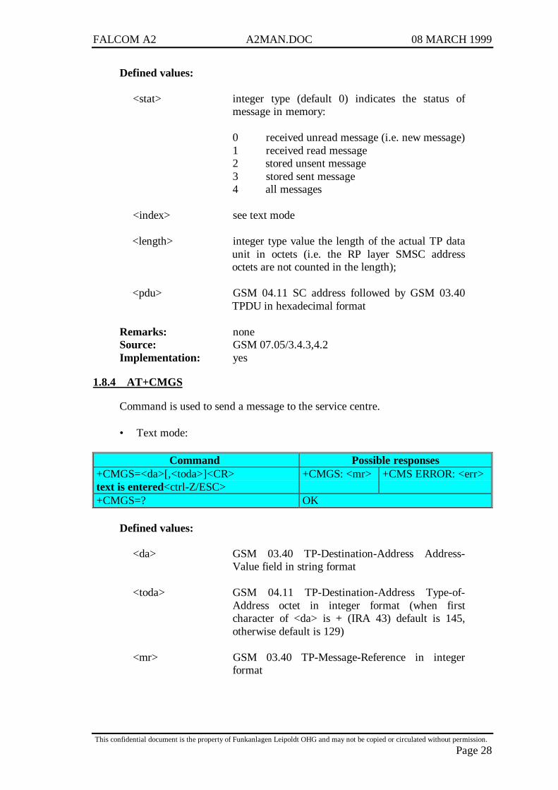
1.8.4 AT+CMGS
Command is used to send a message to the service centre.
• Text mode:
Command Possible responses+CMGS=<da>[,<toda>]<CR>text is entered<ctrl-Z/ESC>
+CMGS: <mr> +CMS ERROR: <err>
+CMGS=? OK
Defined values:
<da> GSM 03.40 TP-Destination-Address Address-Value field in string format
<toda> GSM 04.11 TP-Destination-Address Type-of-Address octet in integer format (when firstcharacter of <da> is + (IRA 43) default is 145,otherwise default is 129)
<mr> GSM 03.40 TP-Message-Reference in integerformat
FALCOM A2 A2MAN.DOC 08 MARCH 1999
This confidential document is the property of Funkanlagen Leipoldt OHG and may not be copied or circulated without permission.
Page 29
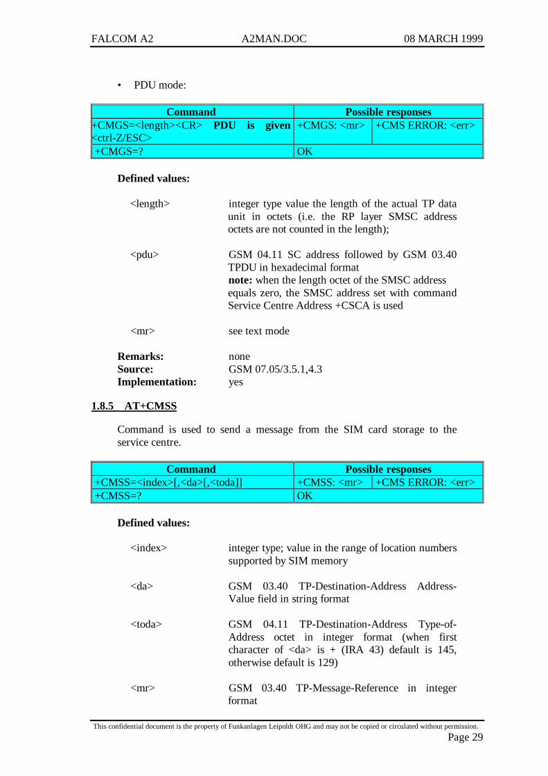
• PDU mode:
Command Possible responses+CMGS=<length><CR> PDU is given<ctrl-Z/ESC>
+CMGS: <mr> +CMS ERROR: <err>
+CMGS=? OK
Defined values:
<length> integer type value the length of the actual TP dataunit in octets (i.e. the RP layer SMSC addressoctets are not counted in the length);
<pdu> GSM 04.11 SC address followed by GSM 03.40TPDU in hexadecimal formatnote: when the length octet of the SMSC addressequals zero, the SMSC address set with commandService Centre Address +CSCA is used
<mr> see text mode
Remarks: noneSource: GSM 07.05/3.5.1,4.3Implementation: yes
1.8.5 AT+CMSS
Command is used to send a message from the SIM card storage to theservice centre.
Command Possible responses+CMSS=<index>[,<da>[,<toda]] +CMSS: <mr> +CMS ERROR: <err>+CMSS=? OK
Defined values:
<index> integer type; value in the range of location numberssupported by SIM memory
<da> GSM 03.40 TP-Destination-Address Address-Value field in string format
<toda> GSM 04.11 TP-Destination-Address Type-of-Address octet in integer format (when firstcharacter of <da> is + (IRA 43) default is 145,otherwise default is 129)
<mr> GSM 03.40 TP-Message-Reference in integerformat

FALCOM A2 A2MAN.DOC 08 MARCH 1999
This confidential document is the property of Funkanlagen Leipoldt OHG and may not be copied or circulated without permission.
Page 30
Remarks: noneSource: GSM 07.05/3.5.2Implementation: yes
1.8.6 AT+CMGW
Command is used to write a message to the SIM card storage.
• Text mode:
Command Possible responses+CMGW=<oa/da>[,<tooa,toda>[,<stat>]]<CR>text is entered<ctrl-Z/ESC>
+CMGW:<index>
+CMS ERROR: <err>
+CMGW=? OK
Defined values:
<oa> GSM 03.40 TP-Originating-Address Address-Value field in string format
<tooa> GSM 04.11 TP-Originating-Address Type-of-Address octet in integer format (default refer<toda>)
<da> GSM 03.40 TP-Destination-Address Address-Value field in string format
<toda> GSM 04.11 TP-Destination-Address Type-of-Address octet in integer format (when firstcharacter of <da> is + (IRA 43) default is 145,otherwise default is 129)
<index> integer type; value in the range of location numberssupported by SIM memory
<stat> string type (default "REC UNREAD");indicates thestatus of message in memory:
"REC UNREAD" received unread message (i.e.new message)
"REC READ" received read message"STO UNSENT" stored unsent message"STO SENT" stored sent message"ALL" all messages
FALCOM A2 A2MAN.DOC 08 MARCH 1999
This confidential document is the property of Funkanlagen Leipoldt OHG and may not be copied or circulated without permission.
Page 31
• PDU mode:
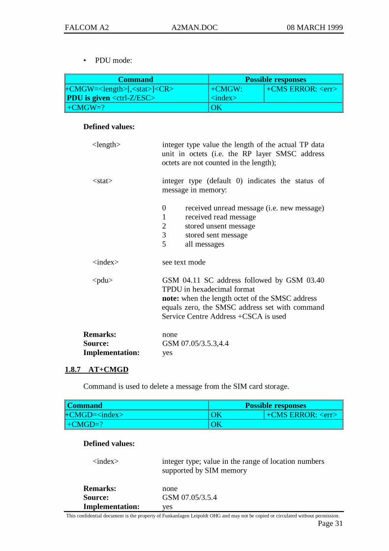
Command Possible responses+CMGW=<length>[,<stat>]<CR> PDU is given <ctrl-Z/ESC>
+CMGW:<index>
+CMS ERROR: <err>
+CMGW=? OK
Defined values:
<length> integer type value the length of the actual TP dataunit in octets (i.e. the RP layer SMSC addressoctets are not counted in the length);
<stat> integer type (default 0) indicates the status ofmessage in memory:
0 received unread message (i.e. new message)1 received read message2 stored unsent message3 stored sent message5 all messages
<index> see text mode
<pdu> GSM 04.11 SC address followed by GSM 03.40TPDU in hexadecimal formatnote: when the length octet of the SMSC addressequals zero, the SMSC address set with commandService Centre Address +CSCA is used
Remarks: noneSource: GSM 07.05/3.5.3,4.4Implementation: yes
1.8.7 AT+CMGD
Command is used to delete a message from the SIM card storage.
Command Possible responses+CMGD=<index> OK +CMS ERROR: <err>+CMGD=? OK
Defined values:
<index> integer type; value in the range of location numberssupported by SIM memory
Remarks: noneSource: GSM 07.05/3.5.4Implementation: yes
FALCOM A2 A2MAN.DOC 08 MARCH 1999
This confidential document is the property of Funkanlagen Leipoldt OHG and may not be copied or circulated without permission.
Page 32
1.9 Message setting commands
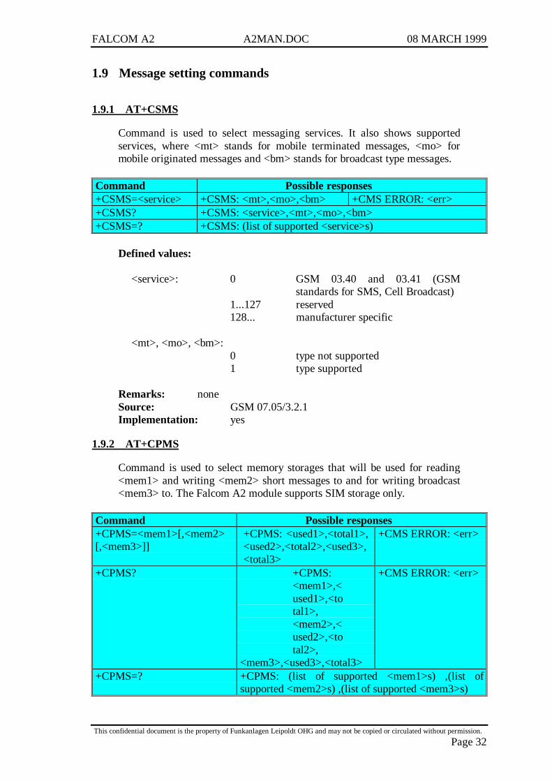
1.9.1 AT+CSMS
Command is used to select messaging services. It also shows supportedservices, where <mt> stands for mobile terminated messages, <mo> formobile originated messages and <bm> stands for broadcast type messages.
Command Possible responses+CSMS=<service> +CSMS: <mt>,<mo>,<bm> +CMS ERROR: <err>+CSMS? +CSMS: <service>,<mt>,<mo>,<bm>+CSMS=? +CSMS: (list of supported <service>s)
Defined values:
<service>: 0 GSM 03.40 and 03.41 (GSMstandards for SMS, Cell Broadcast)
1...127 reserved128... manufacturer specific
<mt>, <mo>, <bm>:0 type not supported1 type supported
Remarks: noneSource: GSM 07.05/3.2.1Implementation: yes
1.9.2 AT+CPMS
Command is used to select memory storages that will be used for reading<mem1> and writing <mem2> short messages to and for writing broadcast<mem3> to. The Falcom A2 module supports SIM storage only.
Command Possible responses+CPMS=<mem1>[,<mem2>[,<mem3>]]
+CPMS: <used1>,<total1>,<used2>,<total2>,<used3>,<total3>
+CMS ERROR: <err>
+CPMS? +CPMS:<mem1>,<used1>,<total1>,<mem2>,<used2>,<total2>,
<mem3>,<used3>,<total3>
+CMS ERROR: <err>
+CPMS=? +CPMS: (list of supported <mem1>s) ,(list ofsupported <mem2>s) ,(list of supported <mem3>s)

FALCOM A2 A2MAN.DOC 08 MARCH 1999
This confidential document is the property of Funkanlagen Leipoldt OHG and may not be copied or circulated without permission.
Page 33
Defined values:
<mem1> string type; memory from which messages are readand deleted (commands List Messages +CMGL,Read Message +CMGR and Delete Message+CMGD); defined value:
"SM" SIM message storage
<mem2> string type; memory to which writing and sendingoperations are made (commands Send Messagefrom Storage +CMSS and Write Message toMemory +CMGW)
<mem3> string type; memory to which received SMs arepreferred to be stored (unless forwarded directly toTE; refer command New Message Indications+CNMI); refer <mem1> for defined values
<total1> integer type; total number of message locations in<mem1>
<total2> integer type; total number of message locations in<mem2>
<total3> integer type; total number of message locations in<mem3>
<used1> integer type; number of messages currently in<mem1>
<used2> integer type; number of messages currently in<mem2>
<used3> integer type; number of messages currently in<mem3>
Remarks: noneSource: GSM 07.05/3.2.2Implementation: yes
1.9.3 AT+CMGF
Command is used to select format for incoming and outgoing messages.
Command Possible responses+CMGF=[<mode>] OK+CMGF? +CMGF: <mode>+CMGF=? +CMGF: (list of supported <mode>s)
FALCOM A2 A2MAN.DOC 08 MARCH 1999
This confidential document is the property of Funkanlagen Leipoldt OHG and may not be copied or circulated without permission.
Page 34
Defined values:
<mode>: 0 PDU mode (default when implemented)1 text mode
Remarks: noneSource: GSM 07.07/3.2.3Implementation: yes
1.9.4 AT+CSMP
Command is used to set additional parameters for text mode messages.
Command Possible responses+CSMP=[<fo>[,<vp>[,<pid>[,<dcs>]]]] OK+CSMP? +CSMP: <fo>,<vp>,<pid>,<dcs>+CSMP=? OK
Defined values:
<fo>: first octet of GSM 03.40 SMS-DELIVER, SMS-SUBMIT in integer format (default 17)
<vp>: GSM 03.40 TP-Validity-Period either in integerformat (default 167) or in time-string format
<pid>: GSM 03.40 TP-Protocol-Identifier in integerformat (default 0)
<dcs>: GSM 03.38 SMS Data Coding Scheme (default 0)in integer format
Remarks: noneSource: GSM 07.05/3.3.2Implementation: yes
1.9.5 AT+CSDH
Command controls whether detailed header information is shown in textmode result codes.
Command Possible responses+CSDH=[<show>] OK+CSDH? +CSDH: <show>+CSDH=? +CSDH: (list of supported <show>s)

FALCOM A2 A2MAN.DOC 08 MARCH 1999
This confidential document is the property of Funkanlagen Leipoldt OHG and may not be copied or circulated without permission.
Page 35
Defined values:
<show>: 0 do not show header values defined incommands +CSCA and +CSMP (<sca>,<tosca>, <fo>, <vp>, <pid> and <dcs>) nor<length>, <toda> or <tooa> in +CMT,+CMGL, +CMGR result codes for SMS/PPtext mode
1 show the values in result codes
Remarks: noneSource: GSM 07.05/3.3.3Implementation: yes
1.9.6 AT+CNMI
Command will be documented soon.
1.9.7 AT+CSCB
Command is used to set parameters of how broadcast messages are to bereceived.
Command Possible responses+CSCB=[<mode>[,<mids>[,<dcss>]]]
OK
+CSCB? +CSCB: <mode>,<mids>,<dcss>+CSCB=? +CSCB: (list of supported <modes>s)
Defined values:
<mode>: 0 message types specified in <mids> and<dcss> are accepted
1 message types specified in <mids> and<dcss> are not accepted
<mids>: string type; all different possible combinations ofCBM message identifiers (refer <mid>) (default isempty string); e.g. "0,1,5,320-478,922"
<dcss>: string type; all different possible combinations ofCBM data coding schemes (refer <dcs>) default isempty string); e.g. "0-3,5"
Remarks: noneSource: GSM 07.05/3.3.4Implementation: yes
FALCOM A2 A2MAN.DOC 08 MARCH 1999
This confidential document is the property of Funkanlagen Leipoldt OHG and may not be copied or circulated without permission.
Page 36
1.10 Functionality commands
1.10.1 AT+GCAP
Command gives GSM capabilities information.
Command Possible responses+gcap +GCAP: +CGSM
Remarks: noneSource: GSM 07.07/5.6Implementation: yes
1.10.2 AT+CSCS
Command is used to set and request the implemented character set.Incoming characters are converted to the current used set.
Command Possible responses+CSCS=[<chset>] OK+CSCS? +CSCS: <chset>+CSCS=? +CSCS: (list of supported <chset>s)
Defined values:
<chset> “PCCP437” Code page 437 supported by FalcomA2
Remarks: noneSource: GSM 07.07/5.5Implementation: yes
1.10.3 AT+CLCK
Command is used to set and request the status of the modem or networkfacilities. Special calls could be barred and passwords could be changed.
Command Possible responses+CLCK=<fac>,<mode>[,<passwd>[,<class>]]
OKwhen <mode>=2+CLCK: <status>[,<class1>[<CR><LF>+CLCK: <status>,<class2>[...]]
+CME ERROR: <err>
+CLCK=? +CLCK: (list of supported <fac>s) +CME ERROR: <err>
FALCOM A2 A2MAN.DOC 08 MARCH 1999
This confidential document is the property of Funkanlagen Leipoldt OHG and may not be copied or circulated without permission.
Page 37
Defined values:
<fac> "SC" SIM lock"AO" Barr all outgoing calls"OI" Barr outgoing international calls"OX" Barr outgoing international calls except to
home country
"AI" Barr all incoming calls"IR" Barr incoming calls when roaming outside
the home country"AB" All barring services"AG" All outgoing barring services"AC" All incoming barring services
<mode>: 0 unlock1 lock2 query status
<status>: 0 not active1 active
<passwd>: string type; shall be the same as password specifiedfor the facility from the ME user interface or withcommand Change Password +CPWD
<class x> is a sum of integers each representing a class ofinformation (default 7 equals to all classes):
1 voice2 data4 fax
Remarks: noneSource: GSM 07.07/7.4Implementation: yes
1.10.4 AT+CPWD
Command is used to set or change passwords for the facility locks of thecommand AT+CLCK.
Command Possible responses+CPWD=<fac>,<oldpwd>,<newpwd>
OK +CME ERROR: <err>
+CPWD=? +CPWD: (list of supported<fac>,<pwdlength>s)
+CME ERROR: <err>
FALCOM A2 A2MAN.DOC 08 MARCH 1999
This confidential document is the property of Funkanlagen Leipoldt OHG and may not be copied or circulated without permission.
Page 38
Defined values:
<fac> refer AT+CLCK
<oldpwd>, <newpwd>: string type; <oldpwd> shall be the same aspassword specified for the facility from theME user interface or with commandChange Password +CPWD and <newpwd>is the new password; maximum length ofpassword can be determined with<pwdlength>.
<pwdlength>: integer type maximum length of thepassword for the facility.
Remarks: noneSource: GSM 07.07/7.5Implementation: yes
1.10.5 AT+CFUN
Command is used to set the functionality of the modem. It switches betweentwo power consumption levels.
Command Possible responses+CFUN=[<fun>[,<rst>]] OK +CME ERROR: <err>+CFUN? +CFUN: <fun> +CME ERROR: <err>+CFUN=? +CFUN: (list of supported
<fun>s),(list of supported <rst>s)+CME ERROR: <err>
Defined values:
<fun>: 0 minimum functionality (Transceiver off)
1 full functionality
<rst>: 0 do not reset the ME before setting it to<fun> power level
1 reset the ME before setting it to <fun>power level
Remarks: noneSource: GSM 07.07/8.2Implementation: yes

FALCOM A2 A2MAN.DOC 08 MARCH 1999
This confidential document is the property of Funkanlagen Leipoldt OHG and may not be copied or circulated without permission.
Page 39
1.10.6 AT+CPAS
Command is used to request the phone activity status.
Command Possible responses+CPAS +CPAS: <pas> +CME ERROR: <err>+CPAS=? +CPAS: (list of supported <pas>s) +CME ERROR: <err>
Defined values:
<pas>: 0 ready (ME allows commands from TA/TE)
1 unavailable (ME does not allow commands fromTA/TE)
2 unknown (ME is not guaranteed to respond toinstructions)
3 ringing (ME is ready for commands from TA/TE,but the ringer is active)
4 call in progress (ME is ready for commands fromTA/TE, but a call is in progress)
5 asleep (ME is unable to process commands fromTA/TE because it is in a low functionality state)
Remarks: noneSource: GSM 07.07/8.1Implementation: yes
1.11 Storing/restoring commands
1.11.1 AT&W
Command is used to save modem settings. Stored settings will be availableafter reset or power off.
Command Possible responses&W OK
Remarks: noneSource: GSM 07.07/V.25terImplementation: yes
FALCOM A2 A2MAN.DOC 08 MARCH 1999
This confidential document is the property of Funkanlagen Leipoldt OHG and may not be copied or circulated without permission.
Page 40
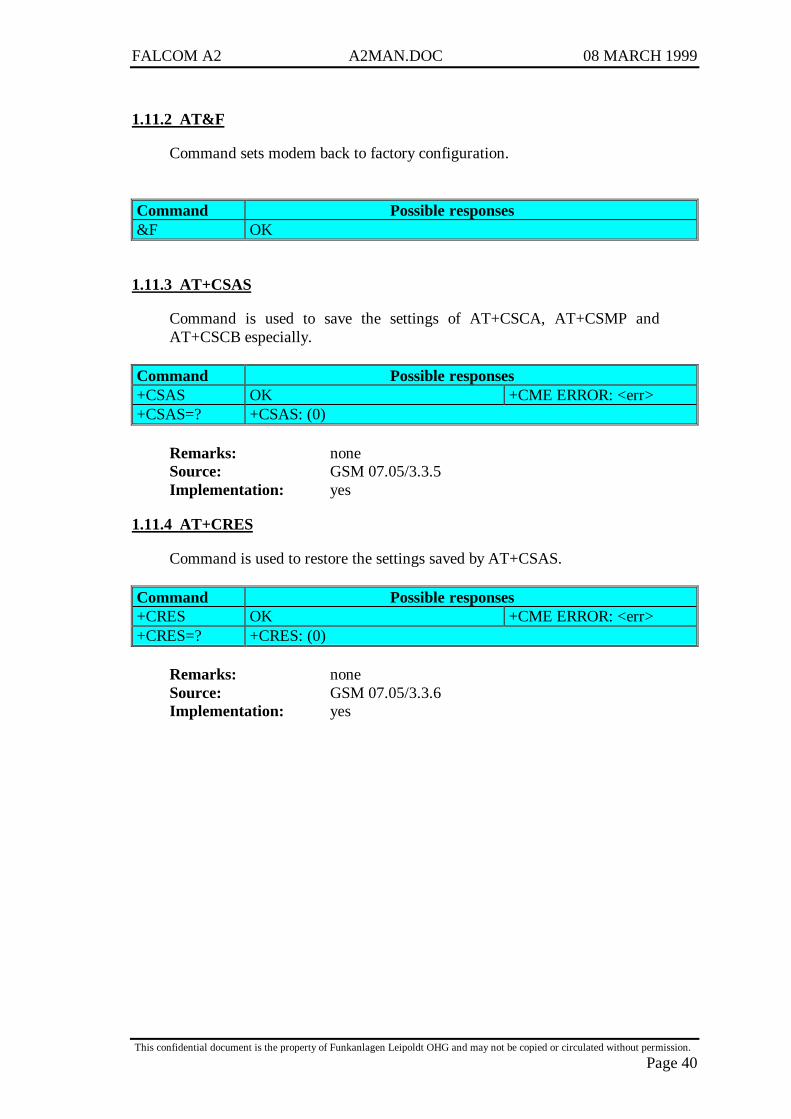
1.11.2 AT&F
Command sets modem back to factory configuration.
Command Possible responses&F OK
1.11.3 AT+CSAS
Command is used to save the settings of AT+CSCA, AT+CSMP andAT+CSCB especially.
Command Possible responses+CSAS OK +CME ERROR: <err>+CSAS=? +CSAS: (0)
Remarks: noneSource: GSM 07.05/3.3.5Implementation: yes
1.11.4 AT+CRES
Command is used to restore the settings saved by AT+CSAS.
Command Possible responses+CRES OK +CME ERROR: <err>+CRES=? +CRES: (0)
Remarks: noneSource: GSM 07.05/3.3.6Implementation: yes
FALCOM A2 A2MAN.DOC 08 MARCH 1999
This confidential document is the property of Funkanlagen Leipoldt OHG and may not be copied or circulated without permission.
Page 41
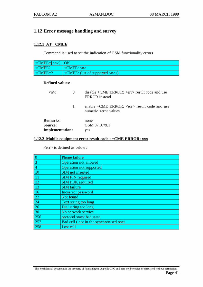
1.12 Error message handling and survey
1.12.1 AT +CMEE
Command is used to set the indication of GSM functionality errors.
+CMEE=[<n>] OK+CMEE? +CMEE: <n>+CMEE=? +CMEE: (list of supported <n>s)
Defined values:
<n>: 0 disable +CME ERROR: <err> result code and useERROR instead
1 enable +CME ERROR: <err> result code and usenumeric <err> values
Remarks: noneSource: GSM 07.07/9.1Implementation: yes
1.12.2 Mobile equipment error result code : +CME ERROR: xxx
<err> is defined as below :
0 Phone failure3 Operation not allowed4 Operation not supported10 SIM not inserted11 SIM PIN required12 SIM PUK required13 SIM failure16 Incorrect password22 Not found24 Text string too long26 Dial string too long30 No network service256 protocol stack bad state257 Bad cell ( not in the synchronised ones258 Lost cell
FALCOM A2 A2MAN.DOC 08 MARCH 1999
This confidential document is the property of Funkanlagen Leipoldt OHG and may not be copied or circulated without permission.
Page 42
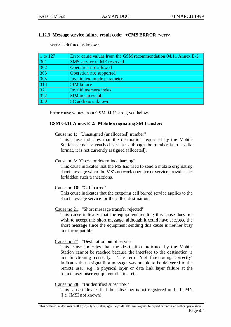
1.12.3 Message service failure result code: +CMS ERROR :<err>
<err> is defined as below :
1 to 127 Error cause values from the GSM recommendation 04.11 Annex E-2301 SMS service of ME reserved302 Operation not allowed303 Operation not supported305 Invalid text mode parameter313 SIM failure321 Invalid memory index322 SIM memory full330 SC address unknown
Error cause values from GSM 04.11 are given below.
GSM 04.11 Annex E-2: Mobile originating SM-transfer:
Cause no 1: "Unassigned (unallocated) number"This cause indicates that the destination requested by the MobileStation cannot be reached because, although the number is in a validformat, it is not currently assigned (allocated).
Cause no 8: "Operator determined barring"This cause indicates that the MS has tried to send a mobile originatingshort message when the MS's network operator or service provider hasforbidden such transactions.
Cause no 10: "Call barred"This cause indicates that the outgoing call barred service applies to theshort message service for the called destination.
Cause no 21: "Short message transfer rejected"This cause indicates that the equipment sending this cause does notwish to accept this short message, although it could have accepted theshort message since the equipment sending this cause is neither busynor incompatible.
Cause no 27: "Destination out of service"This cause indicates that the destination indicated by the MobileStation cannot be reached because the interface to the destination isnot functioning correctly. The term "not functioning correctly"indicates that a signalling message was unable to be delivered to theremote user; e.g., a physical layer or data link layer failure at theremote user, user equipment off-line, etc.
Cause no 28: "Unidentified subscriber"This cause indicates that the subscriber is not registered in the PLMN(i.e. IMSI not known)

FALCOM A2 A2MAN.DOC 08 MARCH 1999
This confidential document is the property of Funkanlagen Leipoldt OHG and may not be copied or circulated without permission.
Page 43
Cause no 29: "Facility rejected"This cause indicates that the facility requested by the Mobile Station isnot supported by the PLMN.
Cause no 30: "Unknown subscriber"This cause indicates that the subscriber is not registered in the HLR(i.e. IMSI or directory number is not allocated to a subscriber).
Cause no 38: "Network out of order"This cause indicates that the network is not functioning correctly andthat the condition is likely to last a relatively long period of time; e.g.,immediately re-attempting the short message transfer is not likely tobe successful.
Cause no 41: "Temporary failure"This cause indicates that the network is not functioning correctly andthat the condition is not likely to last a long period of time; e.g., theMobile Station may wish to try another short message transfer attemptalmost immediately.
Cause no 42: "Congestion"This cause indicates that the short message service cannot be servicedbecause of high traffic.
Cause no 47: "Resources unavailable, unspecified"This cause is used to report a resource unavailable event only when noother cause applies.
Cause no 69: "Requested facility not implemented"This cause indicates that the network is unable to provide therequested short message service.
Cause no 81: "Invalid short message transfer reference value"This cause indicates that the equipment sending this cause hasreceived a message with a short message reference which is notcurrently in use on the MS-network interface.
Cause no 95: "Invalid message, unspecified"This cause is used to report an invalid message event only when noother cause in the invalid message class applies.
Cause no 96: "Invalid mandatory information"This cause indicates that the equipment sending this cause hasreceived a message where a mandatory information element is missingand/or has a content error (the two cases are indistinguishable).
Cause no 97: "Message type non-existent or not implemented"This cause indicates that the equipment sending this cause hasreceived a message with a message type it does not recognise eitherbecause this is a message not defined or defined but not implementedby the equipment sending this cause.
FALCOM A2 A2MAN.DOC 08 MARCH 1999
This confidential document is the property of Funkanlagen Leipoldt OHG and may not be copied or circulated without permission.
Page 44
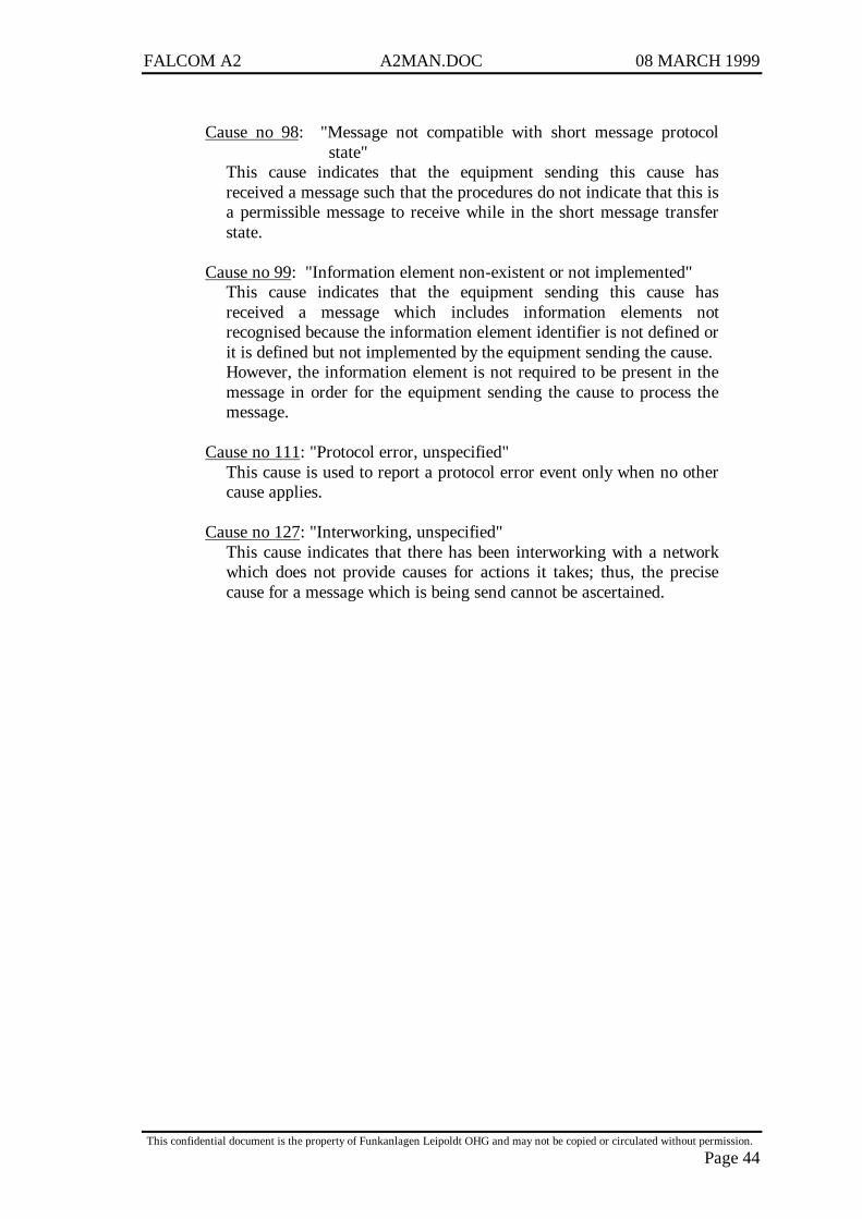
Cause no 98: "Message not compatible with short message protocolstate"
This cause indicates that the equipment sending this cause hasreceived a message such that the procedures do not indicate that this isa permissible message to receive while in the short message transferstate.
Cause no 99: "Information element non-existent or not implemented"This cause indicates that the equipment sending this cause hasreceived a message which includes information elements notrecognised because the information element identifier is not defined orit is defined but not implemented by the equipment sending the cause.However, the information element is not required to be present in themessage in order for the equipment sending the cause to process themessage.
Cause no 111: "Protocol error, unspecified"This cause is used to report a protocol error event only when no othercause applies.
Cause no 127: "Interworking, unspecified"This cause indicates that there has been interworking with a networkwhich does not provide causes for actions it takes; thus, the precisecause for a message which is being send cannot be ascertained.

FALCOM A2 A2MAN.DOC 08 MARCH 1999
This confidential document is the property of Funkanlagen Leipoldt OHG and may not be copied or circulated without permission.
Page 45
1.12.4 AT +CEER
Command is used to show the cause of a failure in the last call-setup or call-modification.
+CMER +CEER: <report>+CMEE=? OK
Defined values:
<report>: cause as written below
Remarks: noneSource: GSM 07.07/6.10Implementation: yes
1.12.5 Cause information element values from GSM recommendation 04.08
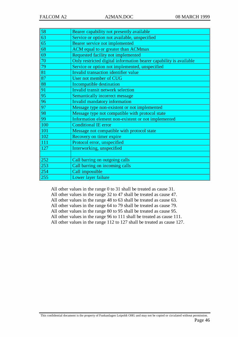
Cause value Diagnostic1 Unassigned (unallocated) number3 No route to destination6 Channel unacceptable8 Operator determined barring16 Normal call clearing17 User busy18 No user responding19 User alerting, no answer21 Call rejected22 Number changed26 Non selected user clearing27 Destination out of order28 Invalid number format (incomplete number)29 Facility rejected30 Response to STATUS ENQUIRY31 Normal, unspecified34 No circuit/channel available38 Network out of order41 Temporary failure42 Switching equipment congestion43 Access information discarded44 requested circuit/channel not available47 Resources unavailable, unspecified49 Quality of service unavailable50 Requested facility not subscribed55 Incoming calls barred with in the CUG57 Bearer capability not authorized
FALCOM A2 A2MAN.DOC 08 MARCH 1999
This confidential document is the property of Funkanlagen Leipoldt OHG and may not be copied or circulated without permission.
Page 46
58 Bearer capability not presently available63 Service or option not available, unspecified65 Bearer service not implemented68 ACM equal to or greater than ACMmax69 Requested facility not implemented70 Only restricted digital information bearer capability is available79 Service or option not implemented, unspecified81 Invalid transaction identifier value87 User not member of CUG88 Incompatible destination91 Invalid transit network selection95 Semantically incorrect message96 Invalid mandatory information97 Message type non-existent or not implemented98 Message type not compatible with protocol state99 Information element non-existent or not implemented100 Conditional IE error101 Message not compatible with protocol state102 Recovery on timer expire111 Protocol error, unspecified127 Interworking, unspecified
252 Call barring on outgoing calls253 Call barring on incoming calls254 Call impossible255 Lower layer failure
All other values in the range 0 to 31 shall be treated as cause 31.All other values in the range 32 to 47 shall be treated as cause 47.All other values in the range 48 to 63 shall be treated as cause 63.All other values in the range 64 to 79 shall be treated as cause 79.All other values in the range 80 to 95 shall be treated as cause 95.All other values in the range 96 to 111 shall be treated as cause 111.All other values in the range 112 to 127 shall be treated as cause 127.
FALCOM A2 A2MAN.DOC 08 MARCH 1999
This confidential document is the property of Funkanlagen Leipoldt OHG and may not be copied or circulated without permission.
Page 47
2 A2-A / A2-B
2.1 Technical data
GSM capability:
GSM 900 Phase I including additional features of Phase II
GSM Teleservices:
TS11 TelephonyTS12 Emergency callTS21 Short message, Point–To-Point, Mobile terminatedTS22 Short message, Point-To-Point, Mobile originatedTS23 Short message cell broadcast
GSM data services:
300 ... 9600 bps, asynchronous, transparent and non-transparent(V.21, V.22, V.22bis, V.32, V.110)
Dimensions (L x W x H in mm):
83,0 x 50,5 x 10,5 for the A2-A (module with mounting brackets)72,0 x 50,5 x 10,5 for the A2-B (module without mounting brackets)
Weight (in g):
53 for the A2-A51 for the A2-B
Temperature range (in °C):
-25.......+ 55 in operation-40.......+ 85 for storage
Power RF output (in W):
2 GSM Class 4 (33 dBm)
Sensitivity (in dBm):
< -102
Supply voltage (in V):
5 (±5%) (consider peak current of 2A for GSM bursts !)
FALCOM A2 A2MAN.DOC 08 MARCH 1999
This confidential document is the property of Funkanlagen Leipoldt OHG and may not be copied or circulated without permission.
Page 48
Average current (in mA at 5V nominal):
0,015 in SOFT OFF mode36 in idle mode (base station sends at –85 dBm)250 in transmit mode at power level 7290 in transmit mode at power level 5 (Maximum)
SIM card Reader:
Internal, for small SIM cards (5/3V)
RS 232:
±12V RX,TX only3V RX,TX,RTS,CTS,DTR,DSR,DCD,RI300..19200 Baud rates for serial link
2.2 Possible external devices:
Audio:
10KΩ differential Microphone impedance2,1Volts Microphone bias voltage56dBSPL/-36dbPA Microphone sensitivity0,4mA Microphone input current45dB Microphone signal-to-noise-ratio
32Ω Speaker impedance100dBSPL/100mVRMS Speaker volume4% at 1.13 Volts RMS< 2% at 100 mV RMS THD
Ringer:
1 kHz, 50 % duty cycle
Keypad:
5 x 4 matrix
Display:
16 x 4, alphanumeric, with backlight
SIM card reader:
External, 10 .. 15cm maximum cable length
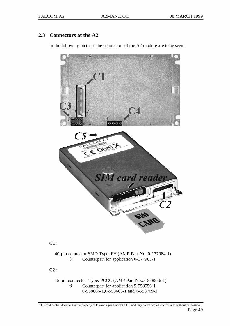
FALCOM A2 A2MAN.DOC 08 MARCH 1999
This confidential document is the property of Funkanlagen Leipoldt OHG and may not be copied or circulated without permission.
Page 49
2.3 Connectors at the A2
In the following pictures the connectors of the A2 module are to be seen.
C1 :
40-pin connector SMD Type: FH (AMP-Part No.:0-177984-1)à Counterpart for application 0-177983-1
C2 :
15 pin connector Type: PCCC (AMP-Part No.:5-558556-1)à Counterpart for application 5-558556-1,
0-558666-1,0-558665-1 and 0-558709-2
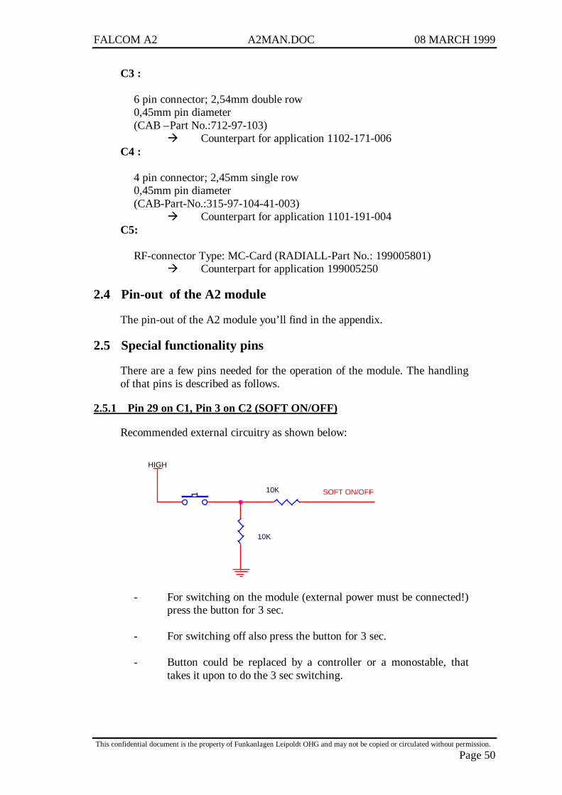
FALCOM A2 A2MAN.DOC 08 MARCH 1999
This confidential document is the property of Funkanlagen Leipoldt OHG and may not be copied or circulated without permission.
Page 50
C3 :
6 pin connector; 2,54mm double row0,45mm pin diameter(CAB –Part No.:712-97-103)
à Counterpart for application 1102-171-006C4 :
4 pin connector; 2,45mm single row0,45mm pin diameter(CAB-Part-No.:315-97-104-41-003)
à Counterpart for application 1101-191-004C5:
RF-connector Type: MC-Card (RADIALL-Part No.: 199005801)à Counterpart for application 199005250
2.4 Pin-out of the A2 module
The pin-out of the A2 module you’ll find in the appendix.
2.5 Special functionality pins
There are a few pins needed for the operation of the module. The handlingof that pins is described as follows.
2.5.1 Pin 29 on C1, Pin 3 on C2 (SOFT ON/OFF)
Recommended external circuitry as shown below:
HIGH
SOFT ON/OFF10K
10K
- For switching on the module (external power must be connected!)press the button for 3 sec.
- For switching off also press the button for 3 sec.
- Button could be replaced by a controller or a monostable, thattakes it upon to do the 3 sec switching.
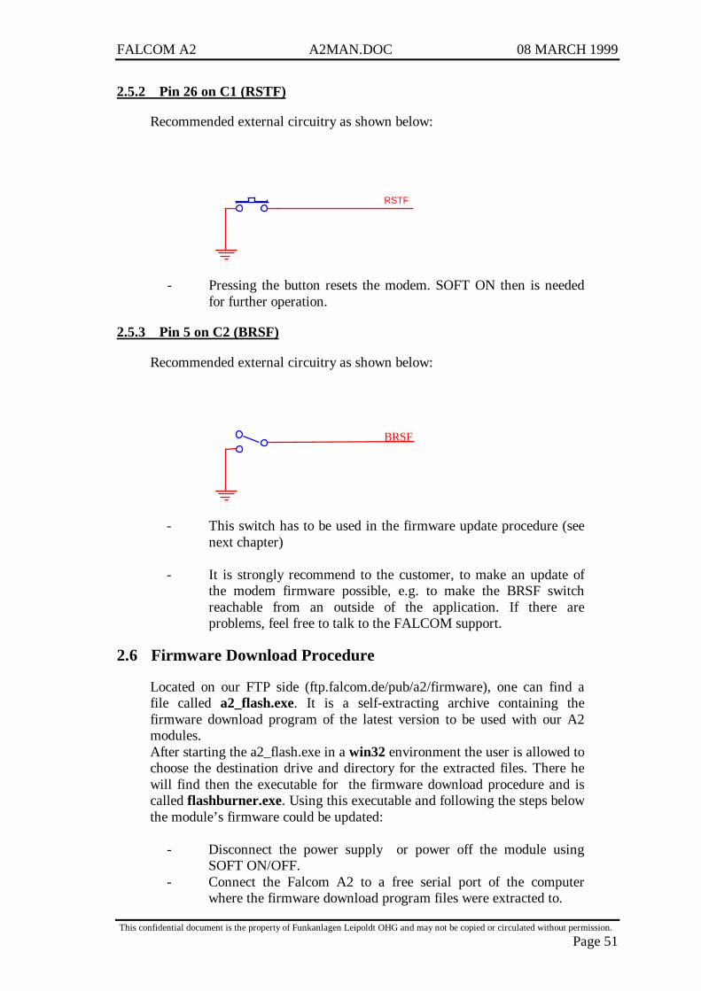
FALCOM A2 A2MAN.DOC 08 MARCH 1999
This confidential document is the property of Funkanlagen Leipoldt OHG and may not be copied or circulated without permission.
Page 51
2.5.2 Pin 26 on C1 (RSTF)
Recommended external circuitry as shown below:
RSTF
- Pressing the button resets the modem. SOFT ON then is neededfor further operation.
2.5.3 Pin 5 on C2 (BRSF)
Recommended external circuitry as shown below:
BRSF
- This switch has to be used in the firmware update procedure (seenext chapter)
- It is strongly recommend to the customer, to make an update ofthe modem firmware possible, e.g. to make the BRSF switchreachable from an outside of the application. If there areproblems, feel free to talk to the FALCOM support.
2.6 Firmware Download Procedure
Located on our FTP side (ftp.falcom.de/pub/a2/firmware), one can find afile called a2_flash.exe. It is a self-extracting archive containing thefirmware download program of the latest version to be used with our A2modules.After starting the a2_flash.exe in a win32 environment the user is allowed tochoose the destination drive and directory for the extracted files. There hewill find then the executable for the firmware download procedure and iscalled flashburner.exe. Using this executable and following the steps belowthe module’s firmware could be updated:
- Disconnect the power supply or power off the module usingSOFT ON/OFF.
- Connect the Falcom A2 to a free serial port of the computerwhere the firmware download program files were extracted to.
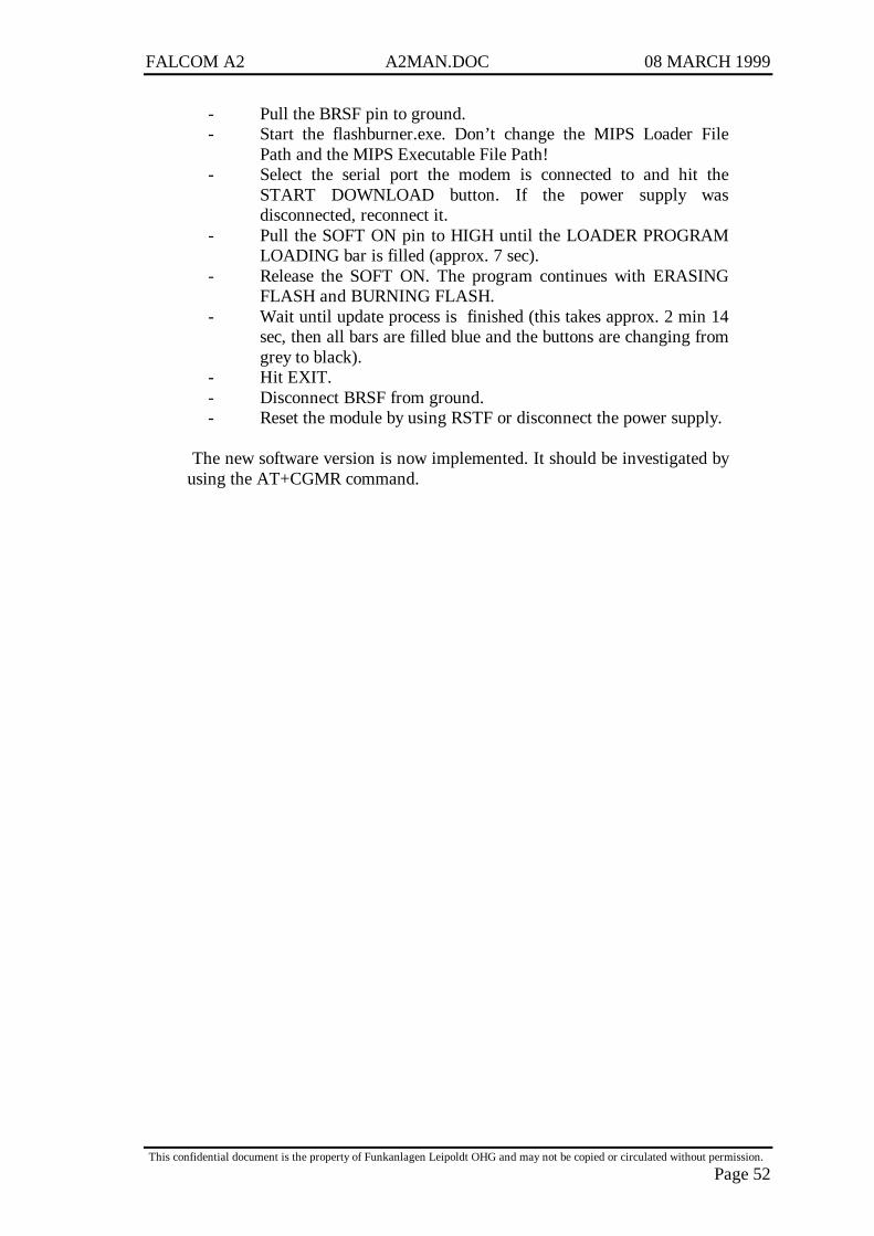
FALCOM A2 A2MAN.DOC 08 MARCH 1999
This confidential document is the property of Funkanlagen Leipoldt OHG and may not be copied or circulated without permission.
Page 52
- Pull the BRSF pin to ground.- Start the flashburner.exe. Don’t change the MIPS Loader File
Path and the MIPS Executable File Path!- Select the serial port the modem is connected to and hit the
START DOWNLOAD button. If the power supply wasdisconnected, reconnect it.
- Pull the SOFT ON pin to HIGH until the LOADER PROGRAMLOADING bar is filled (approx. 7 sec).
- Release the SOFT ON. The program continues with ERASINGFLASH and BURNING FLASH.
- Wait until update process is finished (this takes approx. 2 min 14sec, then all bars are filled blue and the buttons are changing fromgrey to black).
- Hit EXIT.- Disconnect BRSF from ground.- Reset the module by using RSTF or disconnect the power supply.
The new software version is now implemented. It should be investigated byusing the AT+CGMR command.

FALCOM A2 A2MAN.DOC 08 MARCH 1999
This confidential document is the property of Funkanlagen Leipoldt OHG and may not be copied or circulated without permission.
Page 53
3 A2-1 Module
3.1 Technical Data
Dimensions: B x H x L 115mm x 54mm x 33mmWeight: 160gPower Supply: 10,8...31,2 V DC
240mA (max.) 12V45mA (idle) 12V25mA (off) 12V
Temperature Range: Storage: -20°C to +70°CUse: -20°C to +55°C
Interface A: Power supply, Cable Reference
Interface B: RS232 / V24 9 pin D-Sub to DIN 41652
Interface C: RJ 45 8 pin shielded for Audio, RS232 andpower supply.
Interface D: Antenna 50Ω FME female
SIM-Card interface: for small SIM-Cards 3V and 5V

FALCOM A2 A2MAN.DOC 08 MARCH 1999
This confidential document is the property of Funkanlagen Leipoldt OHG and may not be copied or circulated without permission.
Page 54
Audio interface: Electret-MicrophoneLoudspeaker 150ΩGround
3.2 Connectors at the A2-1

FALCOM A2 A2MAN.DOC 08 MARCH 1999
This confidential document is the property of Funkanlagen Leipoldt OHG and may not be copied or circulated without permission.
Page 55
3.3 Functional description
The GSM module FALCOM A2-1 is a mobile station for the transmissionof voice, data and fax calls as well as SMS in GSM networks.The GSM modem FALCOM A2-1 consists of the following components:
• GSM transceiver• Power supply unit• Serial link (V.24) for data transmission and control
If the GSM modem FALCOM A2-1 is registered in the network, it acts justlike a regular fax/data modem. To control the GSM module there is anadvanced set of AT-commands according to GSM ETSI 07.07 and 07.05implemented. The two LED’s on the Interface A are showing the state of theFALCOM A2-1. The yellow LED signals power connection and the greenLED signals a “RESET” function, “SoftOn/Off” procedure or incomingcalls. A incoming call will also be signalled with the internal piezo buzzer.
3.3.1 Ignition line
The ignition line on Interface A controls the „SoftOn/Off“ procedure of theGSM module. If the ignition line will be connected to a high voltage level,the GSM module powered on, and vice versa. The green LED on interface Cshows the „SoftOn/Off“ procedure. After „SoftOn“ the GSM module isready after 10s and the maximum timeout for the „SoftOff“ procedure is20s. Connecting the ignition line permanent to input voltage that„SoftOn/Off“ handling will not be needed.
3.3.2 Serial handling
The GSM modem FALCOM A2-1 allows control of the GSM module overthe interface B or interface C. The interface B is a implementation of a serialinterface corresponding EIA-RS232-C. See table for details:
CCITT V24 Pin Description Direction102 5 Signal Ground (GND)103 3 Transmitted Data (TxD) IN104 2 Received Data (RxD) OUT105 7 Request To Send (RTS) IN106 8 Clear To Send (CTS) OUT107 6 Data Set Ready (DSR) OUT108 4 Data Terminal Ready (DTR) IN109 1 Data Carrier Detect (DCD) OUT125 9 Ring Indicator (RI) OUT
Both interface B and C are not independent usable. The interface B has thehighest priority. If you don’t want to use the interface B you must deactivatethe signals RTS and DTR (or remove connection). With the interface C youhave the audio and control functionality on one interface.See table for connections:
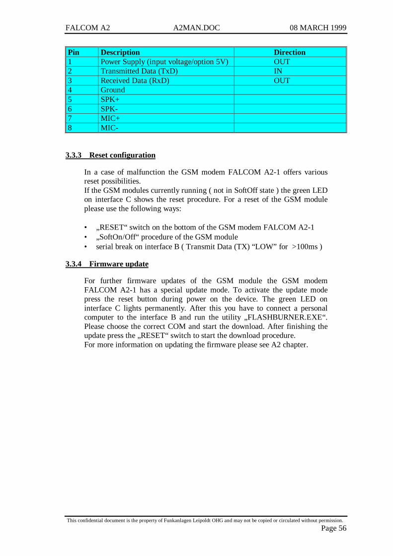
FALCOM A2 A2MAN.DOC 08 MARCH 1999
This confidential document is the property of Funkanlagen Leipoldt OHG and may not be copied or circulated without permission.
Page 56
Pin Description Direction1 Power Supply (input voltage/option 5V) OUT2 Transmitted Data (TxD) IN3 Received Data (RxD) OUT4 Ground5 SPK+6 SPK-7 MIC+8 MIC-
3.3.3 Reset configuration
In a case of malfunction the GSM modem FALCOM A2-1 offers variousreset possibilities.If the GSM modules currently running ( not in SoftOff state ) the green LEDon interface C shows the reset procedure. For a reset of the GSM moduleplease use the following ways:
• „RESET“ switch on the bottom of the GSM modem FALCOM A2-1• „SoftOn/Off“ procedure of the GSM module• serial break on interface B ( Transmit Data (TX) “LOW” for >100ms )
3.3.4 Firmware update
For further firmware updates of the GSM module the GSM modemFALCOM A2-1 has a special update mode. To activate the update modepress the reset button during power on the device. The green LED oninterface C lights permanently. After this you have to connect a personalcomputer to the interface B and run the utility „FLASHBURNER.EXE“.Please choose the correct COM and start the download. After finishing theupdate press the „RESET“ switch to start the download procedure.For more information on updating the firmware please see A2 chapter.
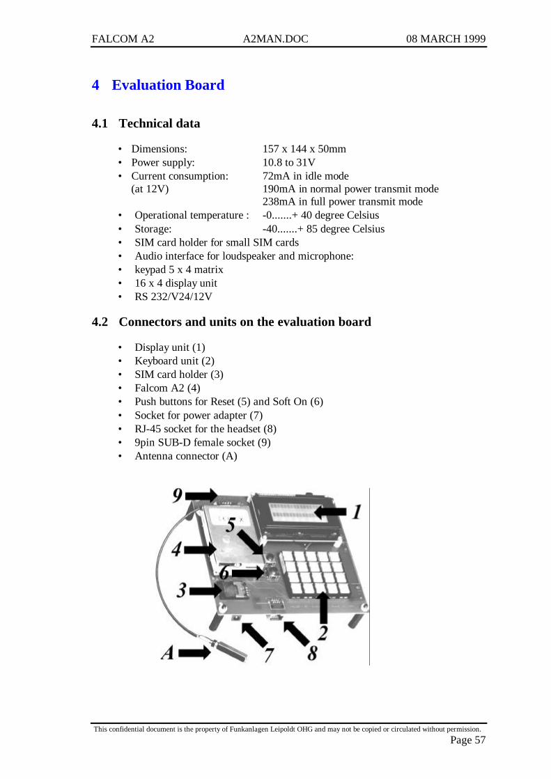
FALCOM A2 A2MAN.DOC 08 MARCH 1999
This confidential document is the property of Funkanlagen Leipoldt OHG and may not be copied or circulated without permission.
Page 57
4 Evaluation Board
4.1 Technical data
• Dimensions: 157 x 144 x 50mm• Power supply: 10.8 to 31V• Current consumption: 72mA in idle mode
(at 12V) 190mA in normal power transmit mode238mA in full power transmit mode
• Operational temperature : -0.......+ 40 degree Celsius• Storage: -40.......+ 85 degree Celsius• SIM card holder for small SIM cards• Audio interface for loudspeaker and microphone:• keypad 5 x 4 matrix• 16 x 4 display unit• RS 232/V24/12V
4.2 Connectors and units on the evaluation board
• Display unit (1)• Keyboard unit (2)• SIM card holder (3)• Falcom A2 (4)• Push buttons for Reset (5) and Soft On (6)• Socket for power adapter (7)• RJ-45 socket for the headset (8)• 9pin SUB-D female socket (9)• Antenna connector (A)
FALCOM A2 A2MAN.DOC 08 MARCH 1999
This confidential document is the property of Funkanlagen Leipoldt OHG and may not be copied or circulated without permission.
Page 58
4.3 Evaluation board and accessories
Inside your evaluation board box you should find the following:
• FALCOM – A2 – Evaluation – Board• Wall mount power adapter• 9-pin serial cable (pin to pin direct, male to female)• update and serial transmission cable (9-pin to 15-pin with switch)• GSM antenna and cable (30cm) with coaxial plug• Headset with RJ-45 plug• Set of connectors (see appendix for details)
- 2 pieces 40-pin stacking connector (plug and socket)- 2 pieces coaxial antenna plug (plug and socket)- 2 pieces 15-pin cable connector (plug and socket)
• 1.44 - disk of test software• 1.44 - disk of layout data (PROTEL/GERBER format)• Falcom A2 command list
4.4 Functional overview
The evaluation board consists of three main components. First is the FalcomA2 module. It has the GSM transmitter inside and provides access to it byuse of two possible serial links and the GSM command set. The Falcom A2module has its own SIM card holder, an antenna connector and two otherconnectors. One of them is a 15-pin plug-socket and the other one is a 40-pin board to board connector. The pin-out of them you can find in theappendix. The second main component is the display. It is a 16 x 4 characterdisplay with background lights. It is used to display the so called “handyfunctions” of the GSM module like phonebook, dial state and SMS texts.Third is the 5 x 4 push button matrix keyboard. From here many of thefunctions of the Falcom A2 could be controlled except the data services,because of their need of a full character terminal display and keyboard.
4.5 User MMI description
4.5.1 Make it work
After unpacking the evaluation board please check contents using the listgiven in chapter 1. Then check the connections from the board to themodule, the display and the keypad. Put a valid SIM card into the holder (3).Plug the headset into its socket (8). Connect the serial link cable to the 9-pinSUB-D socket (9) to a computer communication port (COM1, COM2 etc.).At last put the antenna to a place where it could “see” a GSM network andplug its connector into the Falcom module. You are now ready to power theboard up by connecting the power supply both to mains and to theevaluation board (7).Press the Soft On button for three seconds. After ashort while “Hello” should appear on the screen. If that is true, pleaseproceed to the next section. If nothing or something wrong happens, pleasecheck power and connections. The module should have a close connection

FALCOM A2 A2MAN.DOC 08 MARCH 1999
This confidential document is the property of Funkanlagen Leipoldt OHG and may not be copied or circulated without permission.
Page 59
at the 6 and 4–pin connectors and at its 40-pin connector to the board. Don’tuse any other equipment than that what you got from us unless you havegood experience in using the board and the module.
4.5.2 Keypad overview
UP/DOWN Press to control the Key-tone Level, the Ringer Volume,and the Speaker Volume. Press to scroll forwards /backwards through the menus, submenus, and settings.Press to scroll up or down to different fields on the inputscreen.
Send Press to the "dialled" number and make a call. Press toanswer a call.
End Press to end a phone call. Press and hold to turn on / offthe power. Press to go to the previous display mode.
Clear Press to delete characters or numbers one by one. Pressand hold to clear entire field.
RCL Press to recall the last dialled phone number. Press againto clear entire field.
Menu Press to enter the menu mode.
Select Press to choose the first option displayed in each menuand to find information in the phone book.
4.5.3 Display overview
i Indicates that a Short Message has been received. Whenflashing the memory is full.
Bars Display that the phone is registered on the network. If theyaren’t light up, then the phone is outside the network. Alsothey are showing current signal strength at the location ofthe phone. If there are more bars, the signal is better.
FALCOM A2 A2MAN.DOC 08 MARCH 1999
This confidential document is the property of Funkanlagen Leipoldt OHG and may not be copied or circulated without permission.
Page 60
4.5.4 SIM card issues
Inserting a SIM Card
This SIM card fits into the SIM card holder under theplastic cover at the and close it by pushing the metal flapto "CLOSE".
Using the PIN Code PIN (Personal Identification Number)
The PIN code is a secret code to protect and control accessto your personal SIM card. If the PIN code feature isenabled, you will be prompted to enter it after you turn onthe phone. To enter your PIN code, use the number keys toenter the PIN digits, then press "#" key. If the PIN code isnot entered correctly after three attempts, further PINentry attempts will be blocked and the message "UnblckPIN" will be displayed. This feature protects your phonefrom unauthorised tampering. Enter the PersonalUnblocking Key (see Personal Unblocking Key below),then enter your PIN Code to access your SIM. If you havemore questions concerning PIN or SIM, contact thenetwork operator who supplied the SIM.
PIN2 The second Personal Identification Number, PIN2 is usedto control access to specific functions provided on yourSIM. When you attempt to access these functions, youmay be prompted to enter your PIN2 code. The method ofentering PIN2 is the same as for your PIN code: Use thenumber keys to enter the PIN2 digits, then press the "#"key.
PUK (Personal Unblocking Key)
The PUK code is a secret code related to your SIM card. Ifthe message "Unblck PIN" displays on the LCD, then you,must enter the PUK before you access the SIM again witha PIN code. Enter the PUK and your new PIN code asfollows.
**05*PUK*New PIN#
If you enter the wrong PUK ten times, your SIM card willbe disabled permanently. You will have to contact younetwork operator because you can’t change your PUK byyourself.
4.5.5 Switching ON/OFF the Phone
Switching On To turn on the phone, plug in the power supply and pressSoft On for three seconds. If there is no SIM, the phone
FALCOM A2 A2MAN.DOC 08 MARCH 1999
This confidential document is the property of Funkanlagen Leipoldt OHG and may not be copied or circulated without permission.
Page 61
will ask to insert the SIM and will be displayed "InsertSIM" on the LCD. When this has happened, turn off thephone and insert the SIM. If PIN is enabled, the phonemay ask to enter your PIN code and "Enter PIN" will bedisplayed on the LCD. After entering the correct PINcode, the network checks the validity of your SIM, and thephone registers on the network. If PIN is disabled, thenetwork checks SIM`s validity and the phone registers onthe network. The phone is ready for use, then the RSSI barindicators appear on the display.
Switching Off To turn off the phone, press and hold the END/PWR keyor the Soft On button for three seconds or plug out thepower supply.
4.5.6 Basic MMI functions
Emergency Call
Emergency calls "112" can usually be made from thephone in the network service areas. If you don’t have theSIM card you can make an emergency call in the serviceareas. Other national service and emergency number differfrom one country to another. You can obtain thesenumbers from the local service providers.
Making a call Key in the phone number including the area code. If thephone number on the display is correct, press the SENDkey and wait for an answer. To end a call press theEND/PWR key.
Making an international call
In order to make an international call the user needs to keyin the "+" sign. This can be done by pressing and holdingthe "0" button for a second. Then, key in the number andpress the SEND key. To end a call press the END/PWRkey.
Correcting Keying
If you make a keying mistake, you can delete mistakes thelast character or number on the display by pressing theCLEAR key. You can erase everything on the display bypressing and holding the CLEAR key for a second.
Last Number Redial
To redial the last number, press the RCL -"Recall" key andthen the SEND key. You can scroll through the last 10
FALCOM A2 A2MAN.DOC 08 MARCH 1999
This confidential document is the property of Funkanlagen Leipoldt OHG and may not be copied or circulated without permission.
Page 62
dialled phone numbers by repeatedly pressing the RCLkey.
Speed Dialling You can dial phone number assigned to a speed key bypressing and holding the corresponding number key.Otherwise, you can enter the 2-dight memory number (01-99) and press the SEND key.
Answering a CallIf a call is incoming then "Incoming Call" text will bedisplayed on the LCD. Press the SEND key to answer acall. End the call by pressing the END/PWR key.
4.5.7 Other useful Functions
4.5.7.1 Call Forwarding
You can divert your incoming calls to another telephone number.
Call Forwarding Unconditional
This diverts all incoming calls to another telephonenumber.Activation: *21*telephone# + SENDDeactivation: #21*telephone# + SEND
Call Forwarding Busy
This diverts incoming calls if your phone is busy.Activation: *67*telephone# + SENDDeactivation: #67*telephone# + SEND
Call Forwarding No Reply
This diverts incoming calls if you don’t answer them.Activation: *61*telephone# + SENDDeactivation: #61*telephone + SEND
Call Forwarding Not Reachable
This diverts incoming calls if you cant answer (them i. e.when your phone is outside the service area or poweredoff).Activation: *62*telephone# + SENDDeactivation: #62*telephone + SEND
4.5.7.2 Call Barring
If your network service provides this feature, you can restrict the calls madeby your phone.
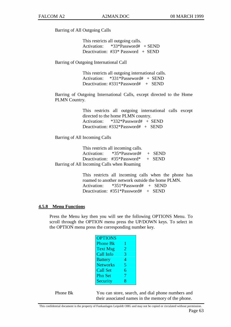
FALCOM A2 A2MAN.DOC 08 MARCH 1999
This confidential document is the property of Funkanlagen Leipoldt OHG and may not be copied or circulated without permission.
Page 63
Barring of All Outgoing Calls
This restricts all outgoing calls.Activation: *33*Password# + SENDDeactivation: #33* Password + SEND
Barring of Outgoing International Call
This restricts all outgoing international calls.Activation: *331*Passeword# + SENDDeactivation: #331*Password# + SEND
Barring of Outgoing International Calls, except directed to the HomePLMN Country.
This restricts all outgoing international calls exceptdirected to the home PLMN country.Activation: *332*Password# + SENDDeactivation: #332*Password# + SEND
Barring of All Incoming Calls
This restricts all incoming calls.Activation: *35*Password# + SENDDeactivation: #35*Password* + SEND
Barring of All Incoming Calls when Roaming
This restricts all incoming calls when the phone hasroamed to another network outside the home PLMN.Activation: *351*Password# + SENDDeactivation: #351*Password# + SEND
4.5.8 Menu Functions
Press the Menu key then you will see the following OPTIONS Menu. Toscroll through the OPTION menu press the UP/DOWN keys. To select inthe OPTION menu press the corresponding number key.
OPTIONSPhone Bk 1Text Msg 2Call Info 3Battery 4Networks 5Call Set 6Phn Set 7Security 8
Phone Bk You can store, search, and dial phone numbers andtheir associated names in the memory of the phone.
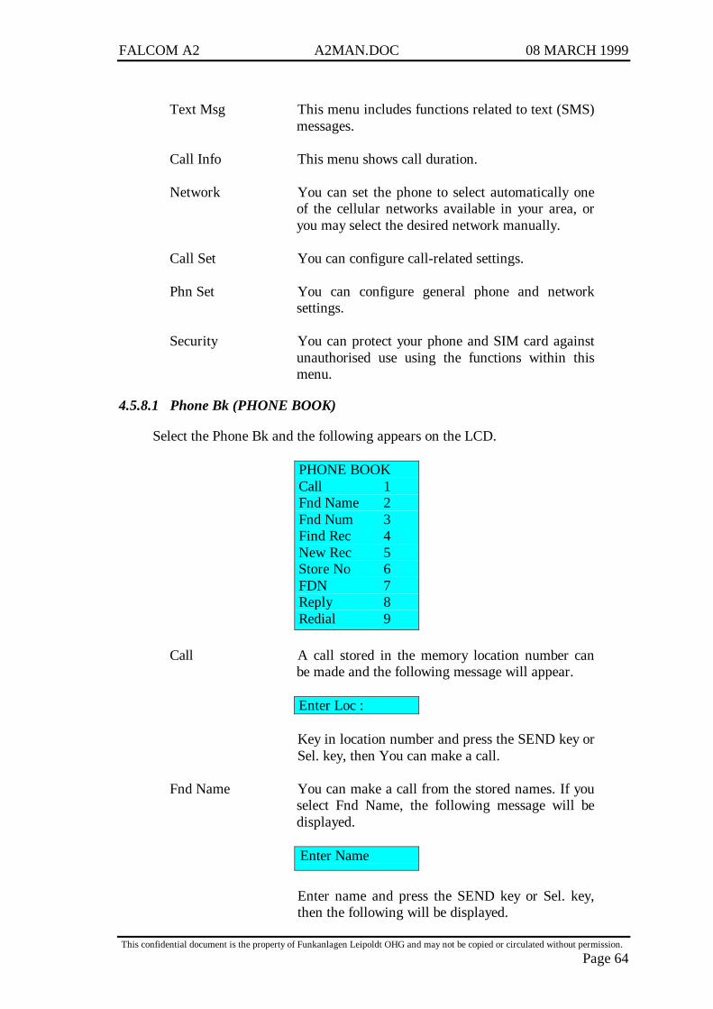
FALCOM A2 A2MAN.DOC 08 MARCH 1999
This confidential document is the property of Funkanlagen Leipoldt OHG and may not be copied or circulated without permission.
Page 64
Text Msg This menu includes functions related to text (SMS)messages.
Call Info This menu shows call duration.
Network You can set the phone to select automatically oneof the cellular networks available in your area, oryou may select the desired network manually.
Call Set You can configure call-related settings.
Phn Set You can configure general phone and networksettings.
Security You can protect your phone and SIM card againstunauthorised use using the functions within thismenu.
4.5.8.1 Phone Bk (PHONE BOOK)
Select the Phone Bk and the following appears on the LCD.
PHONE BOOKCall 1Fnd Name 2Fnd Num 3Find Rec 4New Rec 5Store No 6FDN 7Reply 8Redial 9
Call A call stored in the memory location number canbe made and the following message will appear.
Enter Loc :
Key in location number and press the SEND key orSel. key, then You can make a call.
Fnd Name You can make a call from the stored names. If youselect Fnd Name, the following message will bedisplayed.
Enter Name
Enter name and press the SEND key or Sel. key,then the following will be displayed.
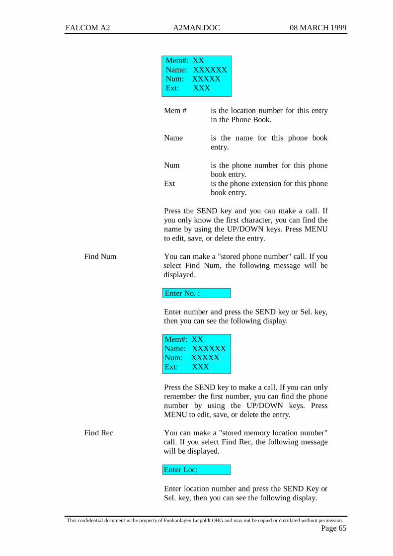
FALCOM A2 A2MAN.DOC 08 MARCH 1999
This confidential document is the property of Funkanlagen Leipoldt OHG and may not be copied or circulated without permission.
Page 65
Mem#: XXName: XXXXXXNum: XXXXXExt: XXX
Mem # is the location number for this entryin the Phone Book.
Name is the name for this phone bookentry.
Num is the phone number for this phonebook entry.
Ext is the phone extension for this phonebook entry.
Press the SEND key and you can make a call. Ifyou only know the first character, you can find thename by using the UP/DOWN keys. Press MENUto edit, save, or delete the entry.
Find Num You can make a "stored phone number" call. If youselect Find Num, the following message will bedisplayed.
Enter No. :
Enter number and press the SEND key or Sel. key,then you can see the following display.
Mem#: XXName: XXXXXXNum: XXXXXExt: XXX
Press the SEND key to make a call. If you can onlyremember the first number, you can find the phonenumber by using the UP/DOWN keys. PressMENU to edit, save, or delete the entry.
Find Rec You can make a "stored memory location number"call. If you select Find Rec, the following messagewill be displayed.
Enter Loc:
Enter location number and press the SEND Key orSel. key, then you can see the following display.
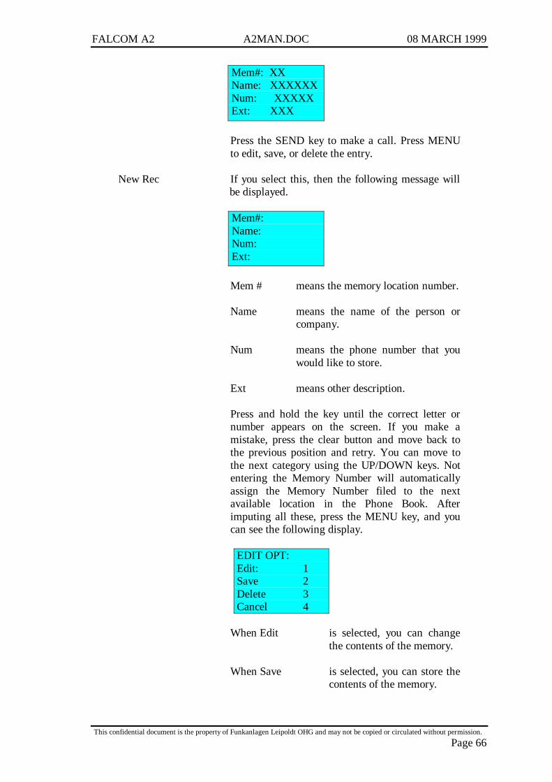
FALCOM A2 A2MAN.DOC 08 MARCH 1999
This confidential document is the property of Funkanlagen Leipoldt OHG and may not be copied or circulated without permission.
Page 66
Mem#: XXName: XXXXXXNum: XXXXXExt: XXX
Press the SEND key to make a call. Press MENUto edit, save, or delete the entry.
New Rec If you select this, then the following message willbe displayed.
Mem#:Name:Num:Ext:
Mem # means the memory location number.
Name means the name of the person orcompany.
Num means the phone number that youwould like to store.
Ext means other description.
Press and hold the key until the correct letter ornumber appears on the screen. If you make amistake, press the clear button and move back tothe previous position and retry. You can move tothe next category using the UP/DOWN keys. Notentering the Memory Number will automaticallyassign the Memory Number filed to the nextavailable location in the Phone Book. Afterimputing all these, press the MENU key, and youcan see the following display.
EDIT OPT:Edit: 1Save 2Delete 3Cancel 4
When Edit is selected, you can changethe contents of the memory.
When Save is selected, you can store thecontents of the memory.
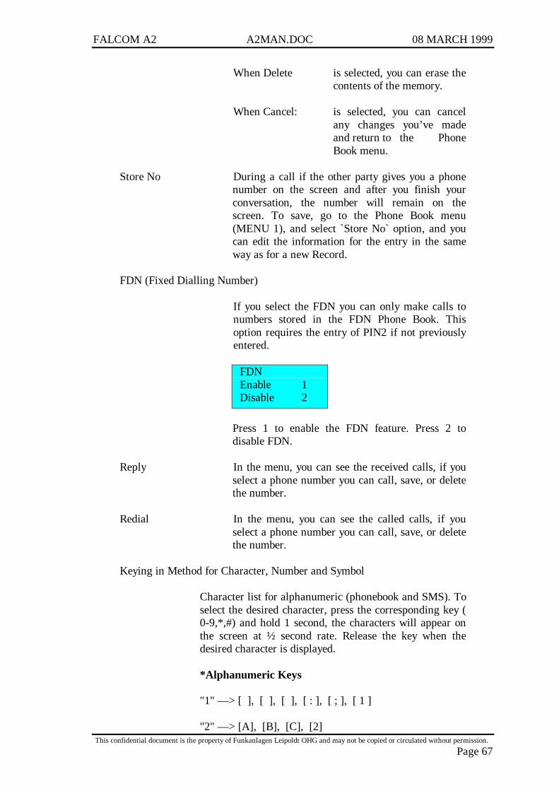
FALCOM A2 A2MAN.DOC 08 MARCH 1999
This confidential document is the property of Funkanlagen Leipoldt OHG and may not be copied or circulated without permission.
Page 67
When Delete is selected, you can erase thecontents of the memory.
When Cancel: is selected, you can cancelany changes you’ve madeand return to the PhoneBook menu.
Store No During a call if the other party gives you a phonenumber on the screen and after you finish yourconversation, the number will remain on thescreen. To save, go to the Phone Book menu(MENU 1), and select `Store No` option, and youcan edit the information for the entry in the sameway as for a new Record.
FDN (Fixed Dialling Number)
If you select the FDN you can only make calls tonumbers stored in the FDN Phone Book. Thisoption requires the entry of PIN2 if not previouslyentered.
FDNEnable 1Disable 2
Press 1 to enable the FDN feature. Press 2 todisable FDN.
Reply In the menu, you can see the received calls, if youselect a phone number you can call, save, or deletethe number.
Redial In the menu, you can see the called calls, if youselect a phone number you can call, save, or deletethe number.
Keying in Method for Character, Number and Symbol
Character list for alphanumeric (phonebook and SMS). Toselect the desired character, press the corresponding key (0-9,*,#) and hold 1 second, the characters will appear onthe screen at ½ second rate. Release the key when thedesired character is displayed.
*Alphanumeric Keys
"1" — > [ ], [ ], [ ], [ : ], [ ; ], [ 1 ]
"2" — > [A], [B], [C], [2]
FALCOM A2 A2MAN.DOC 08 MARCH 1999
This confidential document is the property of Funkanlagen Leipoldt OHG and may not be copied or circulated without permission.
Page 68
"3" — > [D], [E], [F], [3]
"4" — > [G], [H], [I], [4]
"5" — > [J], [K], [L], [5]
"6" — > [M], [N], [O], [6]
"7" — > [P], [Q] [R], [S], [7]
"8" — > [T], [U], [V], [8]
"9" — > [W], [X], [Y], [Z], [9]
"0" — > [+], [-], [<], [>], [=], [0]
"*" — > [?], [!], [?], [!], [*]
"#" — > ["], [""], [ ( ], [ ) ], [ # ]
Storing a phone number with a Name
1 Press Options, Phone Bk, New Rec
2 "Mem#" keying in memory number"Name" keying in name"Number" keying in phone number"Ext" keying in other information
2 Press Menu and select Save
Recalling a phone number and Name
1 Select Options, Phone Bk, Fnd Name or Find Num
2 Key in the first character(s) or memory number of thedesired name or phone number.
Changing/Deleting a phone Book Entry
You can change / delete the contents of the memory. SeeNew Rec. To change or delete displayed entry, pressmenu, select edit or delete.
4.5.8.2 Text MSG (Short Message Service)
If you select Text Msg, then the followings will be displayed.
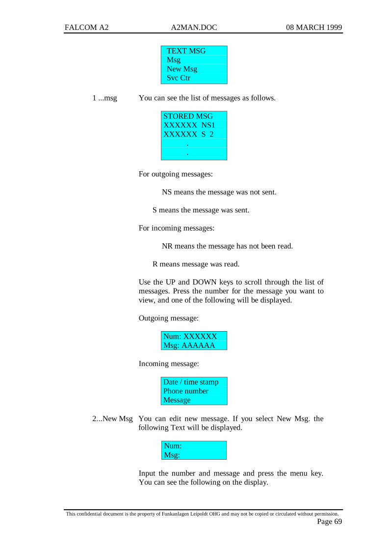
FALCOM A2 A2MAN.DOC 08 MARCH 1999
This confidential document is the property of Funkanlagen Leipoldt OHG and may not be copied or circulated without permission.
Page 69
TEXT MSGMsgNew MsgSvc Ctr
1 ...msg You can see the list of messages as follows.
STORED MSGXXXXXX NS1XXXXXX S 2
.
.
For outgoing messages:
NS means the message was not sent.
S means the message was sent.
For incoming messages:
NR means the message has not been read.
R means message was read.
Use the UP and DOWN keys to scroll through the list ofmessages. Press the number for the message you want toview, and one of the following will be displayed.
Outgoing message:
Num: XXXXXXMsg: AAAAAA
Incoming message:
Date / time stampPhone numberMessage
2...New Msg You can edit new message. If you select New Msg. thefollowing Text will be displayed.
Num:Msg:
Input the number and message and press the menu key.You can see the following on the display.

FALCOM A2 A2MAN.DOC 08 MARCH 1999
This confidential document is the property of Funkanlagen Leipoldt OHG and may not be copied or circulated without permission.
Page 70
SMS OptionSave 1Send 2Save/Snd 3Cancel 4
When Save s selected, you can store the message to theSIM.
When Send is selected, you can transmit the message tothe number.
When Save/Snd is selected, you can store and transmit thesame time.
When Cancel is selected, you can omit the selection.
Press the number key you want to execute. If there is nomore memory available on the SIM to save message, the"SIM Full" message is displayed.
3...Svc Ctr (Service Centre)
In this menu, you can enter the phone number for theservice centre. Press SEND to save the number.
4.5.8.3 CALL INFO
In the option menu, when the number "3" key is pressed, the below menu isdisplayed.
CALL INFOLast 1All 2Reset 3Set Max 4
Last If you select "Last", you can see the time of the last phonecall.
Last Call:00 : 00
00 : 00 is the duration of the last phone call. The first`00`means the minutes, the latter `00`means the second.
All You can see the time of all of the phone calls by selectingAll. Then the following will be displayed.
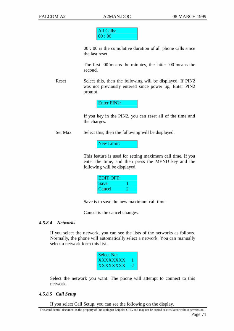
FALCOM A2 A2MAN.DOC 08 MARCH 1999
This confidential document is the property of Funkanlagen Leipoldt OHG and may not be copied or circulated without permission.
Page 71
All Calls:00 : 00
00 : 00 is the cumulative duration of all phone calls sincethe last reset.
The first `00`means the minutes, the latter `00`means thesecond.
Reset Select this, then the following will be displayed. If PIN2was not previously entered since power up, Enter PIN2prompt.
Enter PIN2:
If you key in the PIN2, you can reset all of the time andthe charges.
Set Max Select this, then the following will be displayed.
New Limit:
This feature is used for setting maximum call time. If youenter the time, and then press the MENU key and thefollowing will be displayed.
EDIT OPT:Save 1Cancel 2
Save is to save the new maximum call time.
Cancel is the cancel changes.
4.5.8.4 Networks
If you select the network, you can see the lists of the networks as follows.Normally, the phone will automatically select a network. You can manuallyselect a network form this list.
Select NetXXXXXXXX 1XXXXXXXX 2
Select the network you want. The phone will attempt to connect to thisnetwork.
4.5.8.5 Call Setup
If you select Call Setup, you can see the following on the display.

FALCOM A2 A2MAN.DOC 08 MARCH 1999
This confidential document is the property of Funkanlagen Leipoldt OHG and may not be copied or circulated without permission.
Page 72
CALL SETUPDTMF 1Auto Ansr 2Ring Vol 3Spkr Vol 4
DTMF
DTMFONOFF
This option is to enable or disable DTMF "touchtone"sounds when entering numbers during a call. Press 1 toenable DTMF sounds from the speaker and sent to theother party. Press 2 to disable DTMF sounds.
Auto Ansr
AUTO ANSON 1OFF 2
This menu is used for the user who wants to answer thephone call without pressing a key. Press the number "1"key to enable automatic answering. Press the number "2"key to disable automatic answering.
Ring VolPress U/D Arrows>>>>>>>>
>>>>> indicates the ringer volume level, (up to 10 steps)-Adjust the volume of the ringer using the UP/DOWNkeys.
Speaker VolPress U/D Arrows>>>>>>>>
>>>>>> indicates the speaker volume level. Adjust thevolume of the speaker using the UP/DOWN keys.
4.5.8.6 Phn Setup
If you select Phone Setup, you can see the following on the display.
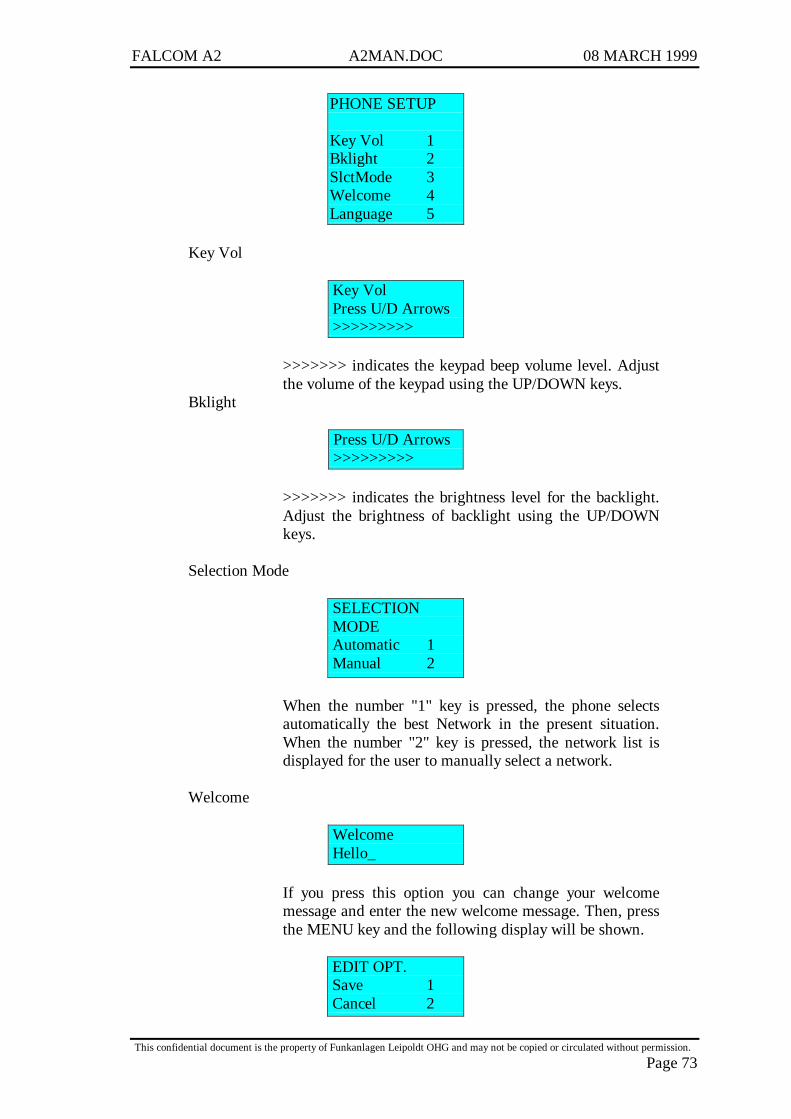
FALCOM A2 A2MAN.DOC 08 MARCH 1999
This confidential document is the property of Funkanlagen Leipoldt OHG and may not be copied or circulated without permission.
Page 73
PHONE SETUP
Key Vol 1Bklight 2SlctMode 3Welcome 4Language 5
Key Vol
Key VolPress U/D Arrows>>>>>>>>>
>>>>>>> indicates the keypad beep volume level. Adjustthe volume of the keypad using the UP/DOWN keys.
Bklight
Press U/D Arrows>>>>>>>>>
>>>>>>> indicates the brightness level for the backlight.Adjust the brightness of backlight using the UP/DOWNkeys.
Selection Mode
SELECTIONMODEAutomatic 1Manual 2
When the number "1" key is pressed, the phone selectsautomatically the best Network in the present situation.When the number "2" key is pressed, the network list isdisplayed for the user to manually select a network.
Welcome
WelcomeHello_
If you press this option you can change your welcomemessage and enter the new welcome message. Then, pressthe MENU key and the following display will be shown.
EDIT OPT.Save 1Cancel 2
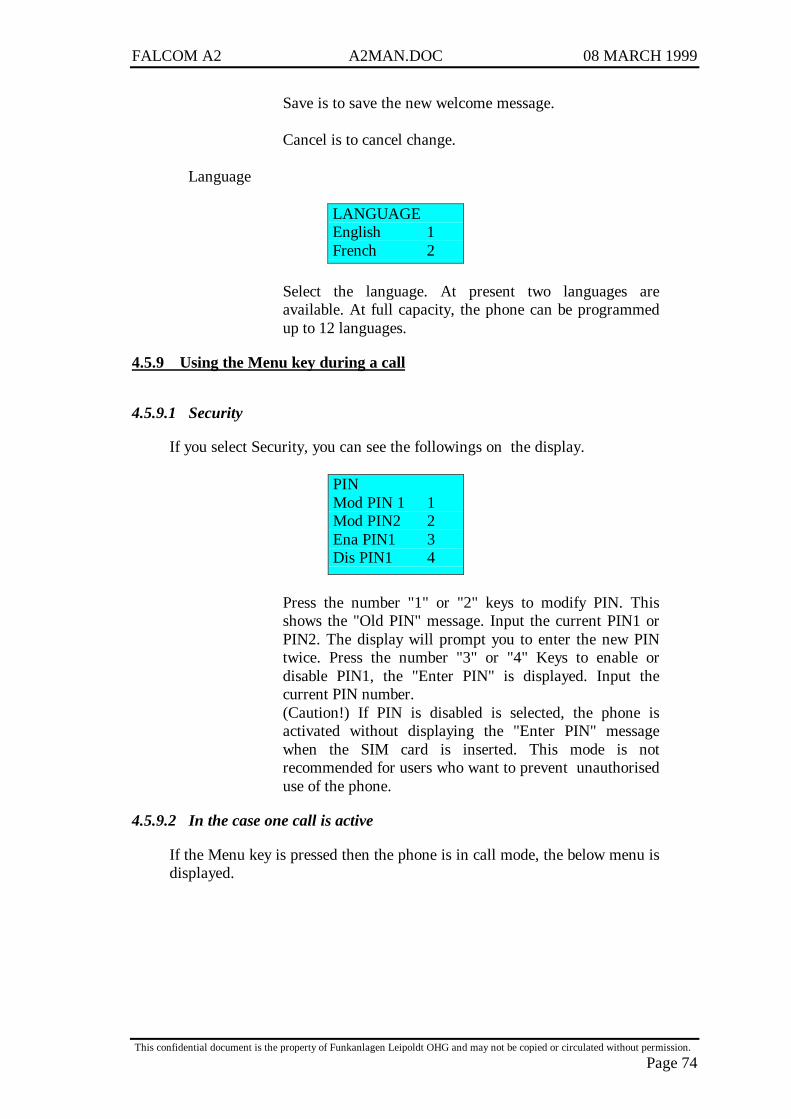
FALCOM A2 A2MAN.DOC 08 MARCH 1999
This confidential document is the property of Funkanlagen Leipoldt OHG and may not be copied or circulated without permission.
Page 74
Save is to save the new welcome message.
Cancel is to cancel change.
Language
LANGUAGEEnglish 1French 2
Select the language. At present two languages areavailable. At full capacity, the phone can be programmedup to 12 languages.
4.5.9 Using the Menu key during a call
4.5.9.1 Security
If you select Security, you can see the followings on the display.
PINMod PIN 1 1Mod PIN2 2Ena PIN1 3Dis PIN1 4
Press the number "1" or "2" keys to modify PIN. Thisshows the "Old PIN" message. Input the current PIN1 orPIN2. The display will prompt you to enter the new PINtwice. Press the number "3" or "4" Keys to enable ordisable PIN1, the "Enter PIN" is displayed. Input thecurrent PIN number.(Caution!) If PIN is disabled is selected, the phone isactivated without displaying the "Enter PIN" messagewhen the SIM card is inserted. This mode is notrecommended for users who want to prevent unauthoriseduse of the phone.
4.5.9.2 In the case one call is active
If the Menu key is pressed then the phone is in call mode, the below menu isdisplayed.
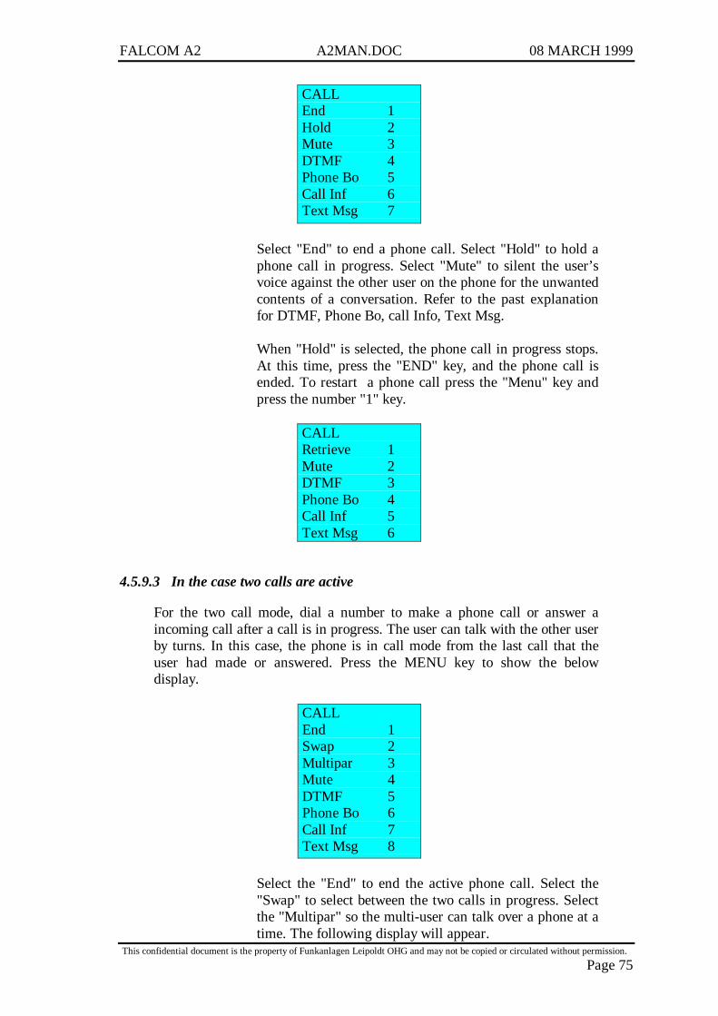
FALCOM A2 A2MAN.DOC 08 MARCH 1999
This confidential document is the property of Funkanlagen Leipoldt OHG and may not be copied or circulated without permission.
Page 75
CALLEnd 1Hold 2Mute 3DTMF 4Phone Bo 5Call Inf 6Text Msg 7
Select "End" to end a phone call. Select "Hold" to hold aphone call in progress. Select "Mute" to silent the user’svoice against the other user on the phone for the unwantedcontents of a conversation. Refer to the past explanationfor DTMF, Phone Bo, call Info, Text Msg.
When "Hold" is selected, the phone call in progress stops.At this time, press the "END" key, and the phone call isended. To restart a phone call press the "Menu" key andpress the number "1" key.
CALLRetrieve 1Mute 2DTMF 3Phone Bo 4Call Inf 5Text Msg 6
4.5.9.3 In the case two calls are active
For the two call mode, dial a number to make a phone call or answer aincoming call after a call is in progress. The user can talk with the other userby turns. In this case, the phone is in call mode from the last call that theuser had made or answered. Press the MENU key to show the belowdisplay.
CALLEnd 1Swap 2Multipar 3Mute 4DTMF 5Phone Bo 6Call Inf 7Text Msg 8
Select the "End" to end the active phone call. Select the"Swap" to select between the two calls in progress. Selectthe "Multipar" so the multi-user can talk over a phone at atime. The following display will appear.

FALCOM A2 A2MAN.DOC 08 MARCH 1999
This confidential document is the property of Funkanlagen Leipoldt OHG and may not be copied or circulated without permission.
Page 76
MULTIPARTYBuild 1Split 2
Select the "Build" to enter a multi user call mode. In thissituation, there are two possibilities to end a call, First, ifthe user wants to end all calls in progress the "End" key. Ifthe user wants to end calls selectively, press the "Split"option in the multiparty Menu. When one call is inprogress and another call is incoming, the below messageis displayed.
2:Incoming
4.5.9.4 Call Waiting
At this time press the "Menu" key, and the below menu will be displayed
CALLReject 1Accept 2Retrieve 3Mute 4DTMF 5Phone Bo 6Call Inf 7Text Msg 8
Select "Reject" to disconnect an incoming call. Select"Accept to answer an incoming call. Select "Retrieve" toget back to the last call.
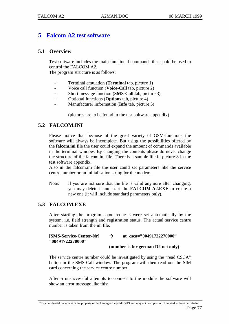
FALCOM A2 A2MAN.DOC 08 MARCH 1999
This confidential document is the property of Funkanlagen Leipoldt OHG and may not be copied or circulated without permission.
Page 77
5 Falcom A2 test software
5.1 Overview
Test software includes the main functional commands that could be used tocontrol the FALCOM A2.The program structure is as follows:
- Terminal emulation (Terminal tab, picture 1)- Voice call function (Voice-Call tab, picture 2)- Short message function (SMS-Call tab, picture 3)- Optional functions (Options tab, picture 4)- Manufacturer information (Info tab, picture 5)
(pictures are to be found in the test software appendix)
5.2 FALCOM.INI
Please notice that because of the great variety of GSM-functions thesoftware will always be incomplete. But using the possibilities offered bythe falcom.ini file the user could expand the amount of commands availablein the terminal window. By changing the contents please do never changethe structure of the falcom.ini file. There is a sample file in picture 8 in thetest software appendix.Also in the falcom.ini file the user could set parameters like the servicecentre number or an initialisation string for the modem.
Note: If you are not sure that the file is valid anymore after changing,you may delete it and start the FALCOM-A2.EXE to create anew one (it will include standard parameters only).
5.3 FALCOM.EXE
After starting the program some requests were set automatically by thesystem, i.e. field strength and registration status. The actual service centrenumber is taken from the ini file:
[SMS-Service-Center-Nr] à at+csca=”00491722270000”"00491722270000"
(number is for german D2 net only)
The service centre number could be investigated by using the “read CSCA”button in the SMS-Call window. The program will then read out the SIMcard concerning the service centre number.
After 5 unsuccessful attempts to connect to the module the software willshow an error message like this:
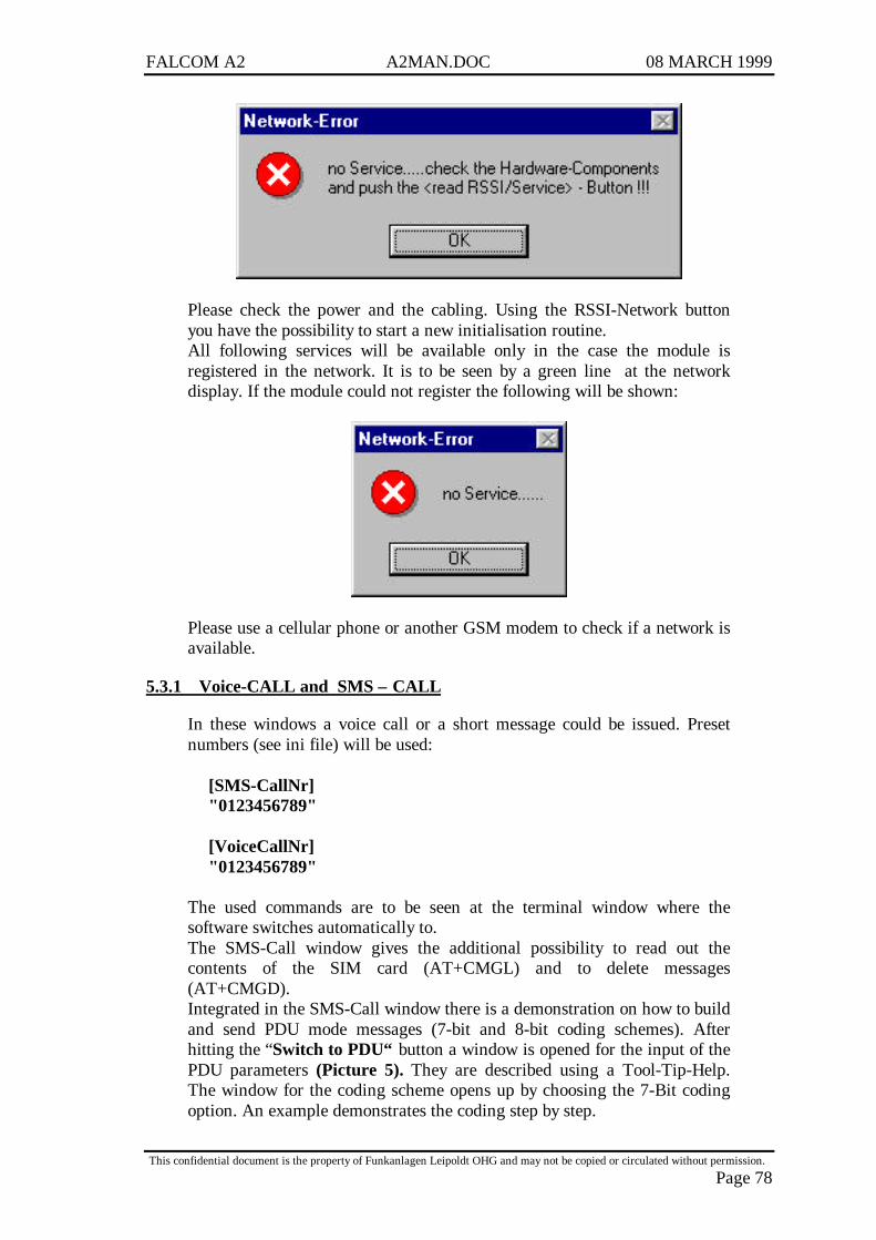
FALCOM A2 A2MAN.DOC 08 MARCH 1999
This confidential document is the property of Funkanlagen Leipoldt OHG and may not be copied or circulated without permission.
Page 78
Please check the power and the cabling. Using the RSSI-Network buttonyou have the possibility to start a new initialisation routine.All following services will be available only in the case the module isregistered in the network. It is to be seen by a green line at the networkdisplay. If the module could not register the following will be shown:
Please use a cellular phone or another GSM modem to check if a network isavailable.
5.3.1 Voice-CALL and SMS – CALL
In these windows a voice call or a short message could be issued. Presetnumbers (see ini file) will be used:
[SMS-CallNr]"0123456789"
[VoiceCallNr]"0123456789"
The used commands are to be seen at the terminal window where thesoftware switches automatically to.The SMS-Call window gives the additional possibility to read out thecontents of the SIM card (AT+CMGL) and to delete messages(AT+CMGD).Integrated in the SMS-Call window there is a demonstration on how to buildand send PDU mode messages (7-bit and 8-bit coding schemes). Afterhitting the “Switch to PDU“ button a window is opened for the input of thePDU parameters (Picture 5). They are described using a Tool-Tip-Help.The window for the coding scheme opens up by choosing the 7-Bit codingoption. An example demonstrates the coding step by step.
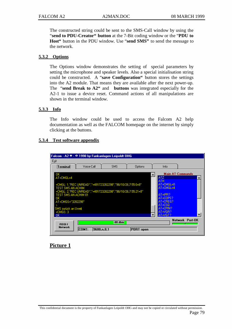
FALCOM A2 A2MAN.DOC 08 MARCH 1999
This confidential document is the property of Funkanlagen Leipoldt OHG and may not be copied or circulated without permission.
Page 79
The constructed string could be sent to the SMS-Call window by using the“send to PDU-Creator“ button at the 7-Bit coding window or the “PDU toHost“ button in the PDU window. Use “send SMS” to send the message tothe network.
5.3.2 Options
The Options window demonstrates the setting of special parameters bysetting the microphone and speaker levels. Also a special initialisation stringcould be constructed. A “save Configuration“ button stores the settingsinto the A2 module. That means they are available after the next power-up.The “send Break to A2“ and buttons was integrated especially for theA2-1 to issue a device reset. Command actions of all manipulations areshown in the terminal window.
5.3.3 Info
The Info window could be used to access the Falcom A2 helpdocumentation as well as the FALCOM homepage on the internet by simplyclicking at the buttons.
5.3.4 Test software appendix
Picture 1
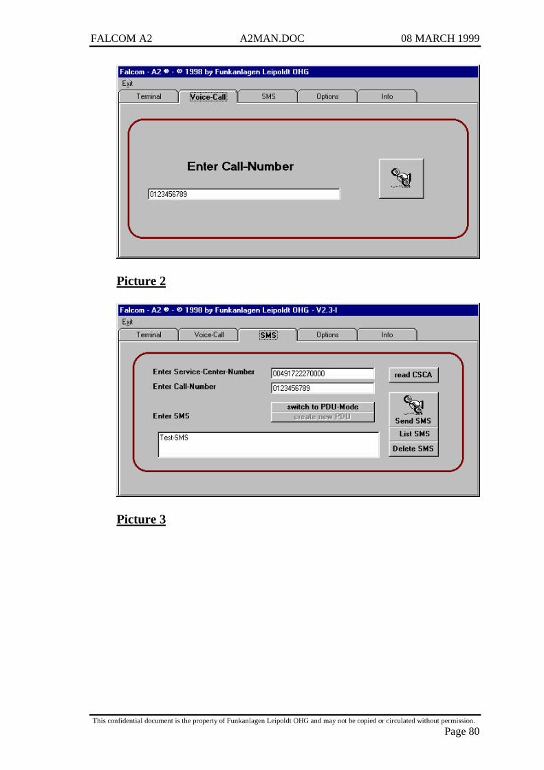
FALCOM A2 A2MAN.DOC 08 MARCH 1999
This confidential document is the property of Funkanlagen Leipoldt OHG and may not be copied or circulated without permission.
Page 80
Picture 2
Picture 3
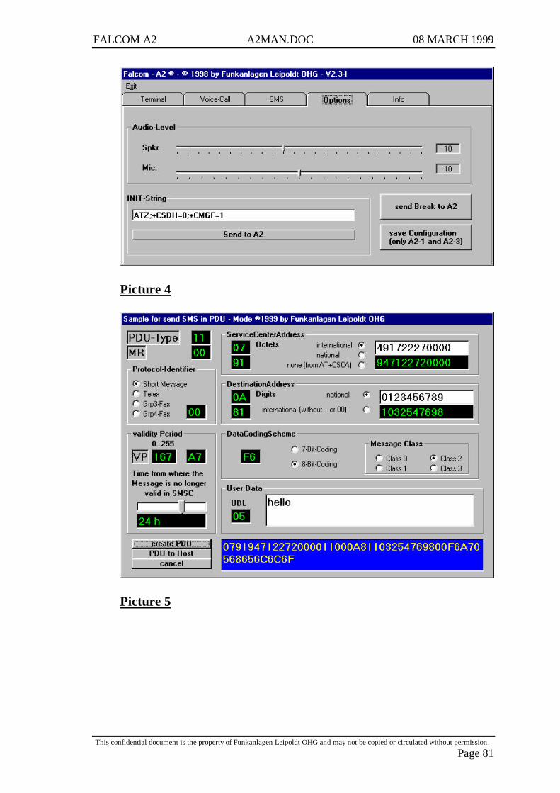
FALCOM A2 A2MAN.DOC 08 MARCH 1999
This confidential document is the property of Funkanlagen Leipoldt OHG and may not be copied or circulated without permission.
Page 81
Picture 4
Picture 5
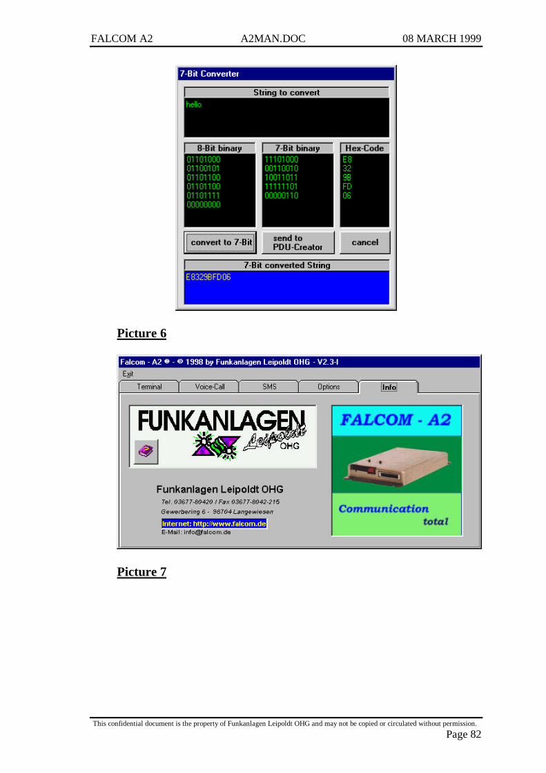
FALCOM A2 A2MAN.DOC 08 MARCH 1999
This confidential document is the property of Funkanlagen Leipoldt OHG and may not be copied or circulated without permission.
Page 82
Picture 6
Picture 7

FALCOM A2 A2MAN.DOC 08 MARCH 1999
This confidential document is the property of Funkanlagen Leipoldt OHG and may not be copied or circulated without permission.
Page 83
Picture 8
do not change the File-Stucture !!!"[Port]1[SMS-Service-Center-Nr]00491722270000" & CHR(34)[SMS-CallNr]0123456789[VoiceCallNr]0123456789[A2-INIT-String]"ATZ;+CSDH=0;+CMGF=1[AT -Commands]ATZAT&W
ATAATH
AT+CMGF=0AT+CMGF=1
AT+CMGL=0AT+CMGL=4AT+CMGL="REC UNREAD"AT+CMGL="ALL"
AT+IPR?AT+COPS?AT+CREG?AT+CSQAT+CPIN?AT+VGR?AT+VGT?AT+VGR=?AT+VGT=?
AT+CGSNAT+CGMRAT+CGMI
ATS0 = 0ATS0 = 1
à Here the user could append own GSM commands !!!!!
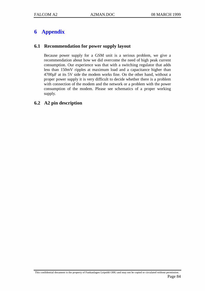
FALCOM A2 A2MAN.DOC 08 MARCH 1999
This confidential document is the property of Funkanlagen Leipoldt OHG and may not be copied or circulated without permission.
Page 84
6 Appendix
6.1 Recommendation for power supply layout
Because power supply for a GSM unit is a serious problem, we give arecommendation about how we did overcome the need of high peak currentconsumption. Our experience was that with a switching regulator that addsless than 150mV ripples at maximum load and a capacitance higher than4700µF at its 5V side the modem works fine. On the other hand, without aproper power supply it is very difficult to decide whether there is a problemwith connection of the modem and the network or a problem with the powerconsumption of the modem. Please see schematics of a proper workingsupply.
6.2 A2 pin description
Pin
#Si
gnal
Nam
e Si
gnal
Typ
e Si
gnal
Lev
elSi
gnal
Des
crip
tion
Cur
rent
ly C
onfig
ured
For
O
ther
Use
s (W
ith d
iffer
ent S
W)
***
1 C
S3
Out
put
CM
OS
Chi
p Se
lect
3 -
(Act
ive
Low
) ***
N
ot S
uppo
rted
in C
urre
nt S
W
Futu
re U
se -
Int
ende
d to
allo
w a
dditi
on o
fge
nera
l pu
rpos
e bi
-dir
ectio
nal
para
llel
port
.2
DA
TA0
Bi-d
irec
tiona
l C
MO
S R
ead
/ Wri
te D
ata
- C
hara
cter
Dis
play
B
i-dir
ectio
nal p
aral
lel p
ort *
**3
DA
TA1
Bi-d
irec
tiona
l C
MO
S R
ead
/ Wri
te D
ata
- C
hara
cter
Dis
play
B
i-dir
ectio
nal p
aral
lel p
ort *
**4
DA
TA2
Bi-d
irec
tiona
l C
MO
S R
ead
/ Wri
te D
ata
- C
hara
cter
Dis
play
B
i-dir
ectio
nal p
aral
lel p
ort *
**5
DA
TA3
Bi-d
irec
tiona
l C
MO
S R
ead
/ Wri
te D
ata
- C
hara
cter
Dis
play
B
i-dir
ectio
nal p
aral
lel p
ort *
**6
DA
TA4
Bi-d
irec
tiona
l C
MO
S R
ead
/ Wri
te D
ata
- C
hara
cter
Dis
play
B
i-dir
ectio
nal p
aral
lel p
ort *
**7
DA
TA5
Bi-d
irec
tiona
l C
MO
S R
ead
/ Wri
te D
ata
- C
hara
cter
Dis
play
B
i-dir
ectio
nal p
aral
lel p
ort *
**8
DA
TA6
Bi-d
irec
tiona
l C
MO
S R
ead
/ Wri
te D
ata
- C
hara
cter
Dis
play
B
i-dir
ectio
nal p
aral
lel p
ort *
**9
DA
TA7
Bi-d
irec
tiona
l C
MO
S R
ead
/ Wri
te D
ata
- C
hara
cter
Dis
play
B
i-dir
ectio
nal p
aral
lel p
ort *
**10
D
ATA
8 B
i-dir
ectio
nal
CM
OS
Rea
d / W
rite
Dat
a -
Cha
ract
er D
ispl
ay
Bi-d
irec
tiona
l par
alle
l por
t ***
or
AD
DR
1 O
utpu
t C
MO
S A
ddre
ss 1
(Not
Jum
pere
d)
Not
Use
d M
emor
y M
appe
d D
ispl
ay11
EN
A
Out
put
CM
OS
Rea
d / W
rite
Ena
ble
(Act
ive
Hig
h) -
C
hara
cter
Dis
play
12
CS2
O
utpu
t C
MO
S C
hip
Sele
ct 2
- (
Act
ive
Low
) -
Cha
ract
er D
ispl
ayor
W
R
Out
put
CM
OS
Wri
te -
(Act
ive
Low
) (N
ot J
umpe
red)
N
ot U
sed
Mem
ory
Map
ped
Dis
play
13
CA
SP_O
N
Bi-d
irec
tiona
l C
MO
S Tu
rns P
hone
On
/ Off
Out
put -
Pho
ne O
n =
Hi
14
KEY
0 O
utpu
t C
MO
S K
eypa
d In
terf
ace
Row
Sel
ect -
15
KEY
1 O
utpu
t C
MO
S K
eypa
d In
terf
ace
Row
Sel
ect
16
KEY
2 O
utpu
t C
MO
S K
eypa
d In
terf
ace
Row
Sel
ect
17
KEY
3 B
i-dir
ectio
nal w
Res
isto
r C
MO
S K
eypa
d R
ow /
Col
umn
- R
ow S
elec
t in
SW (O
utpu
t)18
K
EY4
Bi-d
irec
tiona
l w R
esis
tor
CM
OS
Key
pad
Row
/ C
olum
n -
Row
Sel
ect i
n SW
(Out
put)
19
KEY
5 B
i-dir
ectio
nal w
Res
isto
r C
MO
S K
eypa
d R
ow /
Col
umn
- deb
ounc
e =
46m
s C
olum
n in
SW
(Inp
ut)
20
KEY
6 B
i-dir
ectio
nal w
Res
isto
r C
MO
S K
eypa
d R
ow /
Col
umn
- de
boun
ce =
46m
s C
olum
n in
SW
(Inp
ut)
21
KEY
7 B
i-dir
ectio
nal w
Res
isto
r C
MO
S K
eypa
d R
ow /
Col
umn
- de
boun
ce =
46m
s C
olum
n in
SW
(Inp
ut)
22
KEY
8 B
i-dir
ectio
nal w
Res
isto
r C
MO
S K
eypa
d R
ow /
Col
umn
- de
boun
ce =
46m
s C
olum
n in
SW
(Inp
ut)
23
KEY
9 B
i-dir
ectio
nal w
Res
isto
r C
MO
S K
eypa
d R
ow /
Col
umn
- de
boun
ce =
46m
s C
olum
n in
SW
(Inp
ut)
24
BK
LT_P
WM
O
utpu
t C
MO
S B
ack
Ligh
ting
(Pul
se W
idth
Mod
ulat
ed)
Cha
ract
er D
ispl
ay
Mem
ory
Map
ped
Dis
play
12.8
kH
z, d
uty
cycl
e 90
% O
n25
R
D
Out
put
CM
OS
Exte
rnal
Dev
ice
Rea
d En
able
- (A
ctiv
e Lo
w)
Not
Sup
port
ed in
Cur
rent
SW
26
RST
F In
put
CM
OS
Res
et C
ASP
onl
y - A
ctiv
e Lo
w27
D
ATA
_TX
O
utpu
t C
MO
S R
S-23
2 Tr
ansm
it D
ata
to C
ontr
olle
r
3
00 to
960
0 ba
ud
3840
0 fo
r Loa
der,
1152
00 fo
r Bur
n Fl
ash
28
DA
TA_R
X2
Inpu
t C
MO
S R
S-23
2 R
ecei
ve D
ata
from
Con
trol
ler
3
00 to
960
0 ba
ud
3840
0 fo
r Loa
der,
1152
00 fo
r Bur
n Fl
ash
29
SOFT
_ON
In
put
CM
OS
Togg
le to
turn
pho
ne o
n / o
ff A
ctiv
e H
igh
- Mus
t be
high
for
3 se
cond
s to
togg
le30
R
ING
_PW
M
Out
put
CM
OS
Rin
ger I
nter
face
(Pul
se W
idth
Mod
ulat
ed)
1 kH
z, 5
0 %
dut
y cy
cle
31
RI
Out
put
CM
OS
RS-
232
Rin
g In
dica
tor
(CM
OS
Leve
ls)
RS-
232
Flow
Con
trol
R
ing
indi
catio
n32
D
CD
O
utpu
t C
MO
S R
S-23
2 D
ata
Car
rier
Det
ect
(CM
OS
Leve
ls)
RS-
232
Flow
Con
trol
D
ial t
one
indi
catio
n
VD
D fo
r CM
OS
= 3.
0 V
dc O
utpu
ts a
re 2
.4 V
dc =
1,
0.4
Vdc
= 0
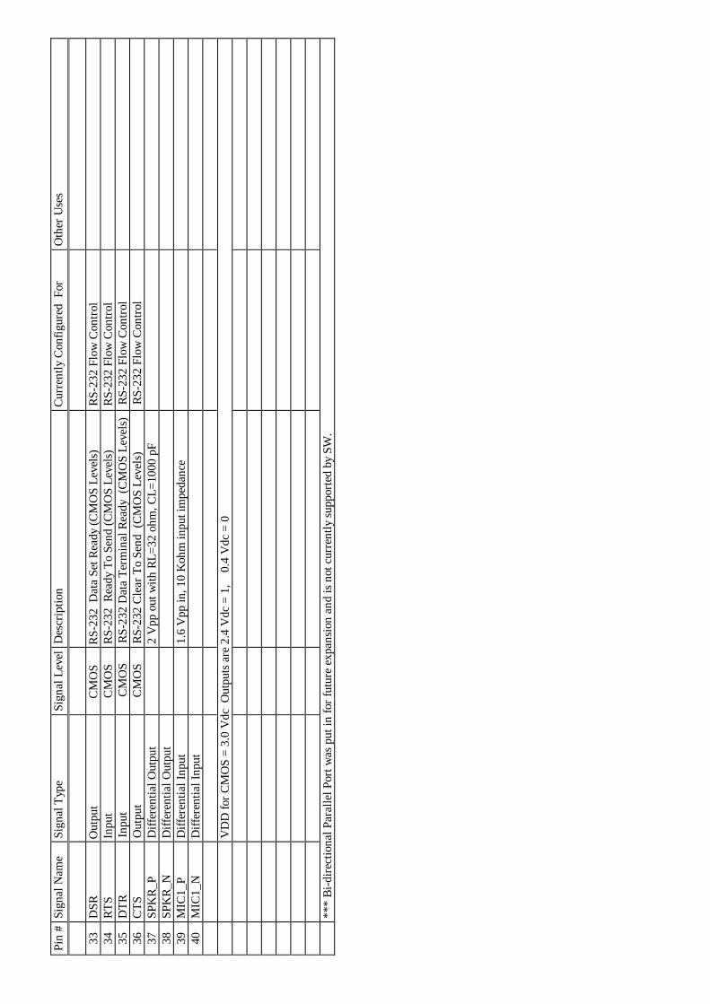
Pin
#Si
gnal
Nam
e Si
gnal
Typ
e Si
gnal
Lev
elD
escr
iptio
n C
urre
ntly
Con
figur
ed F
or
Oth
er U
ses
33
DSR
O
utpu
t C
MO
S R
S-23
2 D
ata
Set R
eady
(CM
OS
Leve
ls)
R
S-23
2 Fl
ow C
ontr
ol34
R
TS
Inpu
t C
MO
S R
S-23
2 R
eady
To
Send
(CM
OS
Leve
ls)
RS-
232
Flow
Con
trol
35
DTR
In
put
CM
OS
RS-
232
Dat
a Te
rmin
al R
eady
(C
MO
S Le
vels
) R
S-23
2 Fl
ow C
ontr
ol36
C
TS
Out
put
CM
OS
RS-
232
Cle
ar T
o Se
nd (
CM
OS
Leve
ls)
RS-
232
Flow
Con
trol
37
SPK
R_P
D
iffer
entia
l Out
put
2 V
pp o
ut w
ith R
L=32
ohm
, CL=
1000
pF
38
SPK
R_N
D
iffer
entia
l Out
put
39
MIC
1_P
Diff
eren
tial I
nput
1.
6 V
pp in
, 10
Koh
m in
put i
mpe
danc
e40
M
IC1_
N
Diff
eren
tial I
nput
VD
D fo
r CM
OS
= 3.
0 V
dc O
utpu
ts a
re 2
.4 V
dc =
1,
0.4
Vdc
= 0
***
Bi-d
irec
tiona
l Par
alle
l Por
t was
put
in fo
r fut
ure
expa
nsio
n an
d is
not
cur
rent
ly s
uppo
rted
by
SW.
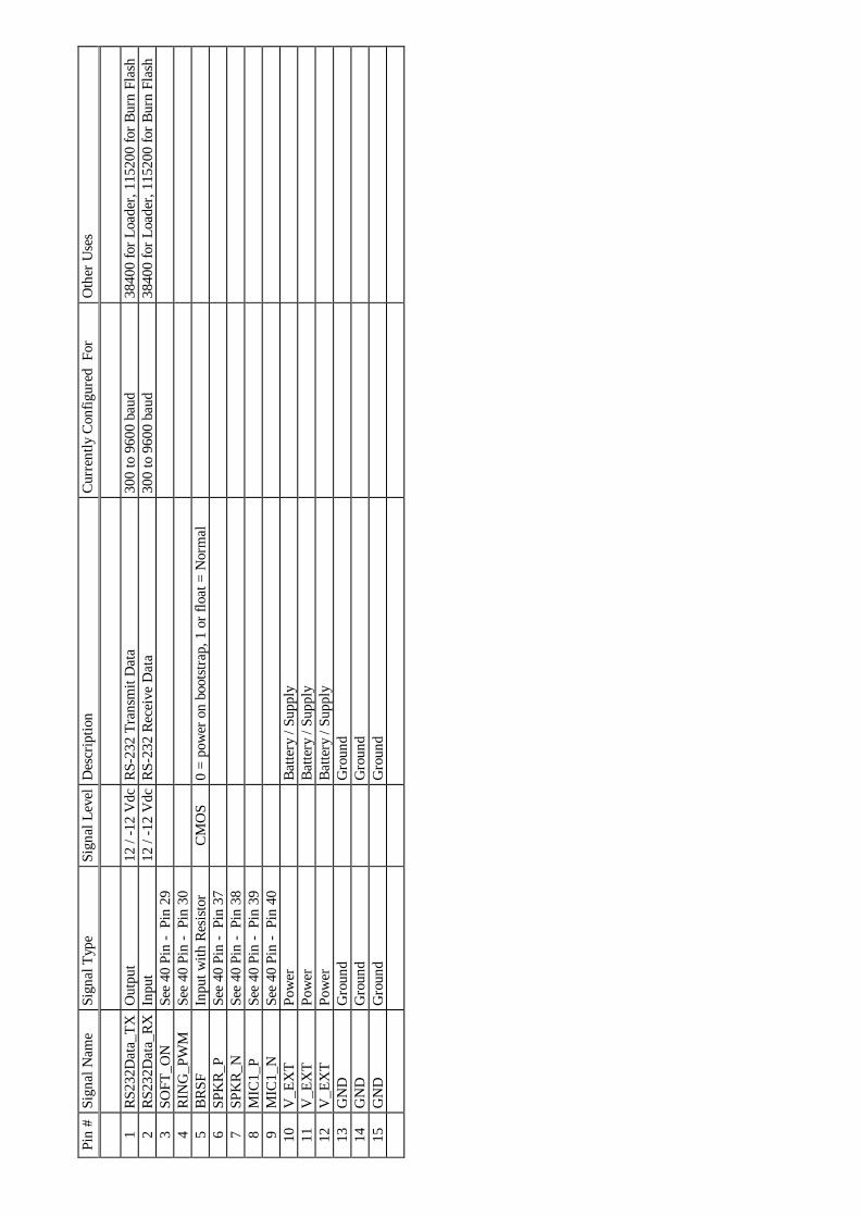
Pin
#Si
gnal
Nam
eSi
gnal
Typ
eSi
gnal
Lev
elD
escr
iptio
nC
urre
ntly
Con
figur
ed F
orO
ther
Use
s
1R
S232
Dat
a_TX
Out
put
12 /
-12
Vdc
RS-
232
Tran
smit
Dat
a30
0 to
960
0 ba
ud38
400
for L
oade
r, 11
5200
for B
urn
Flas
h2
RS2
32D
ata_
RX
Inpu
t12
/ -1
2 V
dcR
S-23
2 R
ecei
ve D
ata
300
to 9
600
baud
3840
0 fo
r Loa
der,
1152
00 fo
r Bur
n Fl
ash
3SO
FT_O
NSe
e 40
Pin
- P
in 2
94
RIN
G_P
WM
See
40 P
in -
Pin
30
5B
RSF
Inpu
t with
Res
isto
rC
MO
S0
= po
wer
on
boot
stra
p, 1
or f
loat
= N
orm
al6
SPK
R_P
See
40 P
in -
Pin
37
7SP
KR
_NSe
e 40
Pin
- P
in 3
88
MIC
1_P
See
40 P
in -
Pin
39
9M
IC1_
NSe
e 40
Pin
- P
in 4
010
V_E
XT
Pow
erB
atte
ry /
Supp
ly11
V_E
XT
Pow
erB
atte
ry /
Supp
ly12
V_E
XT
Pow
erB
atte
ry /
Supp
ly13
GN
DG
roun
dG
roun
d14
GN
DG
roun
dG
roun
d15
GN
DG
roun
dG
roun
d
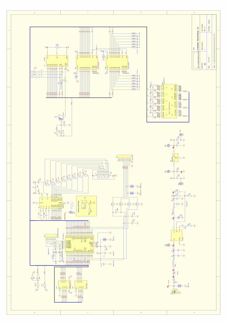
12
34
56
78
ABCD
87
65
43
21
D C B A
Erro
r : L
EIPO
LDT.
BM
P fil
e no
t fou
nd.Ti
tel:
Dim
ensio
n:
Eva
luat
ion
- Boa
rd F
alco
m -
A2
A3
Shee
t-Num
ber:
1
Rev
.-Num
ber:
Rev
. 1.1
Dat
e:9-
Feb-
1999
D
evel
oper
:J.S
keid
e
Dat
ei:
C:\E
igen
e D
atei
en\R
outin
g\C
lient
\Evb
-A2\
EVB_
A2.
Sch
C1
100n
F
C2
100n
F
C3
100n
FC
410
0nF
162738495
1011
J1 DB
9
C5
100n
F
RxD
5
TxD
3R
xD3
CTS
3R
TS3
DSR
3D
TR
3
FIL1 FI
L2 FIL3 FI
L4
FIL5 FI
L6
TxD
5
+
C6
220µ
F/35
VC
847
0nF
L1 47µH
D2
SS24
C10
10nF
C9
470n
F
R1
2,2K
VC
5 R2
5,6K
VC
5
+C
1147
µF
VC
5V
C3
C13
220n
F
FIL7
VC
5
C16
100p
F
C17
100p
F
SPK
1+SP
K1-
MIC
1+M
IC1-
DSR
5C
TS5
DT
R5
RTS
5
R3
2,7K
FIL8
DC
D5
RI5
DC
D3
RI3
C18
100p
F
1 2 3 4 5 6 7 8
J2
SIM
CA
RD
-HO
LDE
R
1 2 3 4 5 6 7 8 9 10
J3
TM
11-C
ON
C14
220n
F
+1 - 2+C
1947
uF
C1+
10
C1-
12
C2+
13
C2-
14
Vs+
11
Vs-
15
VCC9 GND 8
T1I
N7
T1O
UT
2
T2I
N6
T2O
UT
3
R1O
UT
5R
1IN
4
R2O
UT
22R
2IN
23
T3I
N18
T4I
N19
T3O
UT
1
T4O
UT
24
R3O
UT
17R
3IN
16
T5I
N21
T5O
UT
20
U1
AD
M20
7E
C15
220n
F
Vin
5
GN
D3
Vsw
4
FB1
Vc
2
U2
LT10
76
FIL9
FIL1
0
FIL1
1
FIL1
2
L2 47µH
D3
MLA
33V
D4
MLA
5,5V
D7
AU
MLA
18V
D8
AU
MLA
18V
SI1
2A
A1/
D8
10
EN
A11
CS2
/WR
12
CA
SP O
N13
KEY
014
KEY
115
KEY
216
KEY
317
KEY
418
KEY
519
KEY
620
KEY
721
KEY
822
KEY
923
BK
LT P
WM
24
RD
25R
STF
26
DA
TA
TX
27D
AT
A R
X2
28
SOFT
ON
29R
ING
PW
M30
RI
31D
CD
32
DSR
33R
TS34
DT
R35
CTS
36
SPK
R P
37SP
KR
N38
MIC
P39
MIC
N40
D7
9D
68
D5
7D
46
D3
5D
24
D1
3D
02
CS3
1
SIMResetS1
SIMGNDS2
SIMClockS3
SIMVCCS4
SIMDataS5
SIMVCCS6
Vext C1
Vbat C2
DGND C3
AGND C4
U3
FALC
OM
-A2
IN2
OU
T3
GND 1
U4
MIC
2920
A
RST
F
RIN
G P
WM
RIN
G P
WM
Vin
VC
3
G1
A1
2Y
118
A2
4Y
216
A3
6Y
314
A4
8Y
412
VC
320
GN
D10
U5A
74LC
X24
4
G19
A1
11Y
19
A2
13Y
27
A3
15Y
35
A4
17Y
43
U5B
74LC
X24
4
RxD
3R
xD5
TxD
3Tx
D5
DT
R3
RTS
3
DT
R5
RTS
5
DSR
3D
SR5
CTS
3D
CD
3R
I3
CTS
5D
CD
5R
I5
SOFT
_ON
11
3
GND
J4 KLB
5,5
+ C7
4700
µF/6
,3V
Ta1
Res
et
Ta2
Soft-
On
BK
LT
D0
D2
D4
D6
D8
CS2
KEY
0K
EY2
KEY
4K
EY6
KEY
8
CS3
D1
D3
D5
D7
EN
AC
ASP
_ON
KEY
1K
EY3
KEY
5K
EY7
KEY
9R
D
R8
10K
R9
10K
SOFT
_ON
RST
F
VC
3
D0
7
D1
8
D2
9
D3
10
D4
11
D5
12
D6
13
D7
14
RS4
RW
5
E6
LED
+15
LED
-16
VC
C2
VEE
3
GN
D1
U6
Dis
play
VC
5
VC
C1
7
B1
2
B2
3
B3
5
B4
6
B5
8
B6
9
B7
11
B8
12
GN
D4
GN
D10
GN
D39
GN
D45
VC
C2
42
A1
47
A2
46
A3
44
A4
43
A5
41
A6
40
A7
38
A8
37
OE
48
DIR
1
U7A
74FC
T16
4245
T
VC
C1
18
B1
13
B2
14
B3
16
B4
17
B5
19
B6
20
B7
22
B8
23
GN
D15
GN
D21
GN
D28
GN
D34
VC
C2
31
A1
36
A2
35
A3
33
A4
32
A5
30
A6
29
A7
27
A8
26
OE
25
DIR
24
U7B
74FC
T16
4245
T
VC
3
CS2
EN
A
VC
3
VC
3V
C3
VC
3
C21
100n
C22
100n
D8
D7
D6
D5
D4
D3
D2
D1
D0
R11
100K
R12
100K
R13
100K
R14
100K
R15
100K
R16
100K
R17
100K
R18
100K
R19
100K
R20
100K
R21
100K
R22
100K
VC
3V
C3
D0_
DD
1_D
D2_
DD
3_D
D4_
DD
5_D
D6_
DD
7_D
D0_
DD
1_D
D2_
DD
3_D
D4_
DD
5_D
D6_
DD
7_D
RS_
D
RS_
D
EN
A_D
EN
A_D
R23
100K
VC
3
R24 1K
R25 1K
R26 1K
R30
25K
C23
100n
Q1
BC
807
R28
0
BK
LT
D9
MB
R05
20LT
1
D10
MB
R05
20LT
1
D1
1N58
18
VC
5
MP2
3VM
P35V
MP4
GN
D
MP5
Uei
n
C24
470p
F
C25
470p
f
VC
5R
3120
K
R4
5,6K
KEY5
KEY6
KEY7
KEY8
KEY9
KEY0
KEY1
KEY2
KEY3
VC
3R
5
10K
R6
10K
R7
10K
R10
10K
R29
10K
G4G4 G3G3 G2G2 G1G1
K4K4 K3K3 K2K2 K1K1
Mat
rix
- Key
Pad
4x5
Key
's
N4N4 N3N3 N2N2 N1N1
P4P4 P3P3 P2P2 P1P1
J1 J1
J2 J2
J3 J3
J4 J4
J5 J5
L1 L1
L2 L2
L3 L3
L4 L4
L5 L5
M1 M1
M2 M2
M3 M3
M4 M4
M5 M5
H1 H1
H2 H2
H3 H3
H4 H4
H5 H5
C0
C1
C2
C3
R0
R1
R2
R3F1F1
F2F2
F3F3
F4F4
C4
SW1
KEY
B4X
5-FT
MP1
GN
D
MP6
MP
R27
2,7K
*
+C
12 47µF
/10V
+C
20
1000
µF/6
,3V
NPN
2,2K
MP6
20
ΩSP
EAK
ERV
C5
Sam
ple
for c
onne
ct R
inge
r