f mach iiifg mach iii - duro dyne - intro · f mach iiifg mach iii. ... fg mach iii to a new level...
TRANSCRIPT
OWNER’SMANUAL
AUTOMATIC BULK FEED PINSPOTTER
MACHINERY DIVISION
FG MACH IIIFG MACH III
INTRODUCTIONThe FG Mach III Pinspotter was designed utilizing the best cur-rent technology to provide greater insulation fastening power and reliability. The inherent minimal material handling combined with the utilization of welded fasteners will insure your shop of a cost efficient, quality product.
Trouble free service is the foundation on which all Duro Dyne Pin-spotters are built. Proven solid state components are located for easy access. Duro Dyne continues this concept and brings the FG Mach III to a new level of reliability, serviceability and efficiency.
This Guide is designed to help you set up and operate your FG Mach III at peak performance for years to come.
IMPORTANTAlways follow manufacturer’s recommendations for proper safety and handling procedures for all materials used in conjunction with this machine as outlined in Manufacturer’s Safety Data Sheet (MSDS) for each product.
LIMITED WARRANTYDuro Dyne Machinery is manufactured by skilled mechanics, utilizing the latest production techniques. Each unit has been rigorously tested prior to packaging and shipment in order to ensure trouble-free operation.
Your Duro Dyne machine has a two year warranty against defects in material. Any component found to be defective will be repaired or replaced (at the manufacturer’s discretion) at no cost if the faulty component is returned freight prepaid to the nearest Duro Dyne Service Department. The warranty does not apply to expend-able parts or repairs or service due to improper maintenance or operation procedures.
Duro Dyne products have been engineered to maximize operator safety. Unauthorized modification of this product will void the warranty.
All warranty claims must be accompanied by a serial number, date of purchase and the name and address of the distributor it was purchased from.
TABLE OF CONTENTSInstallation Instructions 10Introduction 2Maintenance 14Operation 11Operation Flow Chart 15Parts List 23Parts Locator 3-9Servicing 14Troubleshooting 16-22Warranty 2Wiring Diagrams 12-13
- 2 -
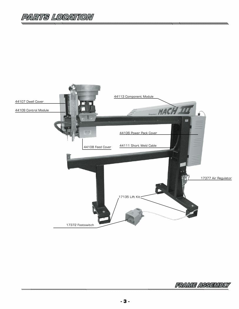
PARTS LOCATION
FRAME ASSEMBLY
- 3 -
44107 Dwell Cover
44108 Feed Cover
44109 Control Module
44113 Component Module
44106 Power Pack Cover
17377 Air Regulator
17372 Footswitch
17135 Lift Kit
44111 Short Weld Cable
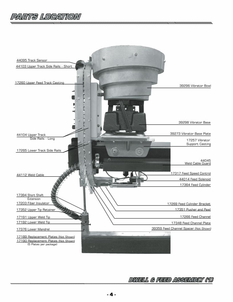
17257 Vibrator Support Casting
44045Weld Cable Guard
17317 Feed Speed Control
44014 Feed Solenoid
17364 Feed Cylinder
17269 Feed Cylinder Bracket
17351 Pusher and Pawl
17266 Feed Channel
17348 Feed Channel Plate
39359 Feed Channel Spacer (Not Shown)
44095 Track Sensor
17260 Upper Feed Track Casting
44104 Upper Track Side Rails - Long
17265 Lower Track Side Rails
44112 Weld Cable
17394 Short Shaft Extension17203 Fiber Insulator
17190 Replacement Plates (Not Shown) (5 Plates per package)
17192 Lower Weld Tip
17189 Replacement Plates (Not Shown)
17191 Upper Weld Tip
17352 Upper Tip Retainer
17376 Lower Mandrel
39296 Vibrator Bowl
39298 Vibrator Base
39273 Vibrator Base Plate
44103 Upper Track Side Rails - Short
PARTS LOCATION
DWELL & FEED ASSEMBLY (1)
- 4 -
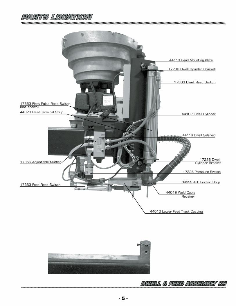
44110 Head Mounting Plate
17363 Dwell Reed Switch
44102 Dwell Cylinder
44116 Dwell Solenoid
17236 Dwell Cylinder Bracket
17325 Pressure Switch
39353 Anti Friction Strip
44010 Lower Feed Track Casting
17363 First Pulse Reed Switch(not shown)
44020 Head Terminal Strip
17356 Adjustable Muffler
17363 Feed Reed Switch
44019 Weld CableRetainer
17236 Dwell Cylinder Bracket
PARTS LOCATION
DWELL & FEED ASSEMBLY (2)
- 5 -
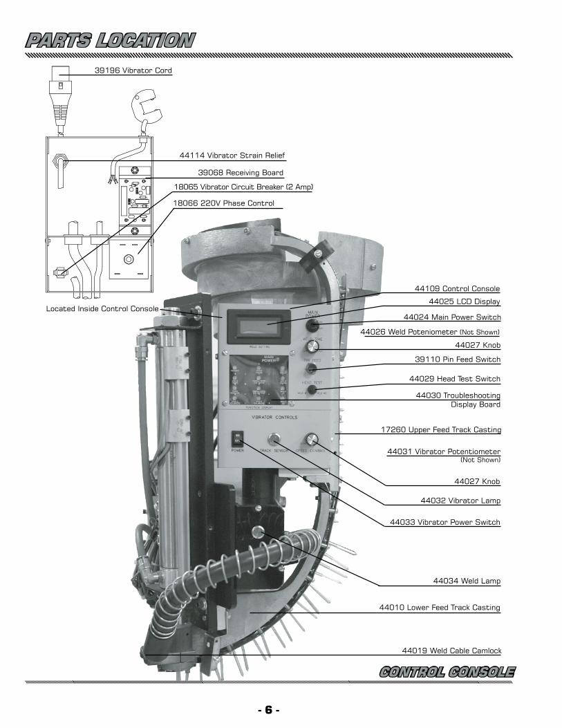
PARTS LOCATION
CONTROL CONSOLE
44026 Weld Poteniometer (Not Shown)
39110 Pin Feed Switch
44025 LCD Display
44024 Main Power Switch
44109 Control Console
44029 Head Test Switch
44030 Troubleshooting Display Board
17260 Upper Feed Track Casting
44031 Vibrator Potentiometer(Not Shown)
44027 Knob
44032 Vibrator Lamp
44033 Vibrator Power Switch
44034 Weld Lamp
44010 Lower Feed Track Casting
18066 220V Phase Control
Located Inside Control Console
44114 Vibrator Strain Relief
18065 Vibrator Circuit Breaker (2 Amp)
44027 Knob
39068 Receiving Board
39196 Vibrator Cord
44019 Weld Cable Camlock
- 6 -
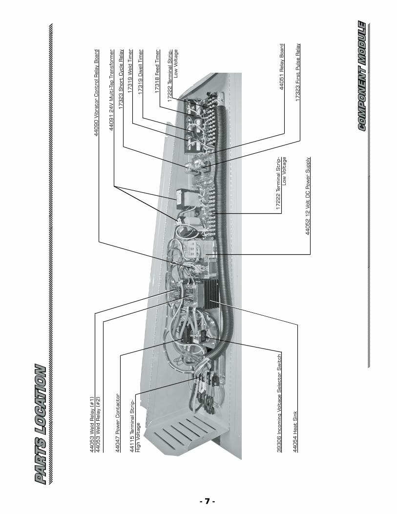
17
31
9 D
wel
l Tim
er
17
22
2 T
erm
inal
Str
ip-
Low
Vol
tage
17
32
3 S
hort
Cyc
le R
elay
17
31
9 W
eld
Tim
er
44
09
0 V
ibra
tor
Con
trol
Rel
ay B
oard
44
05
1 R
elay
Boa
rd
17
32
3 F
irst
Pul
se R
elay
17
22
2 T
erm
inal
Str
ip-
Low
Vol
tage
44
05
2 1
2 V
olt
DC
Pow
er S
uppl
y
44
11
5 T
erm
inal
Str
ip-
Hig
h Vo
ltag
e
44
04
7 P
ower
Con
tact
or
39
30
6 In
com
ing
Volt
age
Sel
ecto
r S
wit
ch
44
05
3 W
eld
Rel
ay (#
1)
44
05
3 W
eld
Rel
ay (#
2)
17
31
8 F
eed
Tim
er
44
05
4 H
eat
Sin
k
44
09
1 2
4V M
ulti
-Tap
Tra
nsfo
rmer
PA
RTS
LO
CAT
ION
CO
MP
ON
EN
T M
OD
ULE
- 7 -
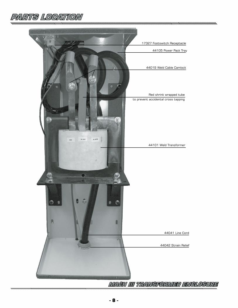
44041 Line Cord
44019 Weld Cable Camlock
17327 Footswitch Receptacle
44105 Power Pack Tray
44101 Weld Transformer
44042 Strain Relief
Red shrink wrapped tube
to prevent accidental cross tapping
PARTS LOCATION
- 8 -
MACH III TRANSFORMER ENCLOSURE
INSTALLATION INSTRUCTIONS1) For the Mach III- Connect the Power Pack to a source of 208-230 V 60 Amp. power. This service should be connected to
a 60 amp disconnect box fitted with 60 amp slow blow fuses. The Power supply line to the Power Pack pigtail should be #6 (or heavier) wire to minimize voltage losses. The black and white wires are the power, the green is ground. Select the closest match to the Power Supply (either 208V or 240V) at the Incom-ing Voltage Selector Switch in the Component Module.
2) Attach the Footswitch to the Footswitch Receptacle on the rear of the Power Pack.
3) Connect the air line to the Regulator. Adjust the regulator pressure to 80-85 PSI.
4) Plug the Vibrator Line Cord into the socket on the rear of the Control Console.
- 9 -
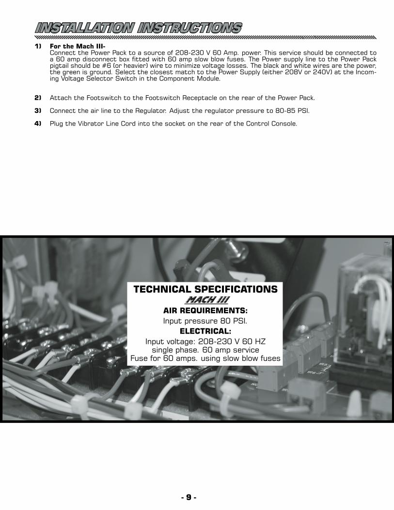
TECHNICAL SPECIFICATIONSMach III
AIR REQUIREMENTS:Input pressure 80 PSI.
ELECTRICAL:Input voltage: 208-230 V 60 HZ
single phase. 60 amp serviceFuse for 60 amps. using slow blow fuses
OPERATIONMach III INITIAL ADJUSTMENTS1) Turn the power switch to “ON”.2) Turn the vibrator switch to “ON”.3) Add the weld pins to the hopper (Vibrator Bowl).
4) Adjust the vibrator speed so that the weld pins climb the spiral track inside the vibrator bowl without vibrating off.
5) When the weld pins fill the track up to the Vibrator Sensor, the vibrator automatically shuts off.6) Flip the HEAD TEST switch to either the “WELD #1” or “WELD #2” position.
NOTE: The Mach III Pinspotter has two redundant weld circuits. In the event that the solid state relay controlling the weld fails you may simply flip the switch to the other circuit and continue produc-tion. A replacement Weld Relay should then be ordered through your local Duro Dyne wholesaler.
- 10 -
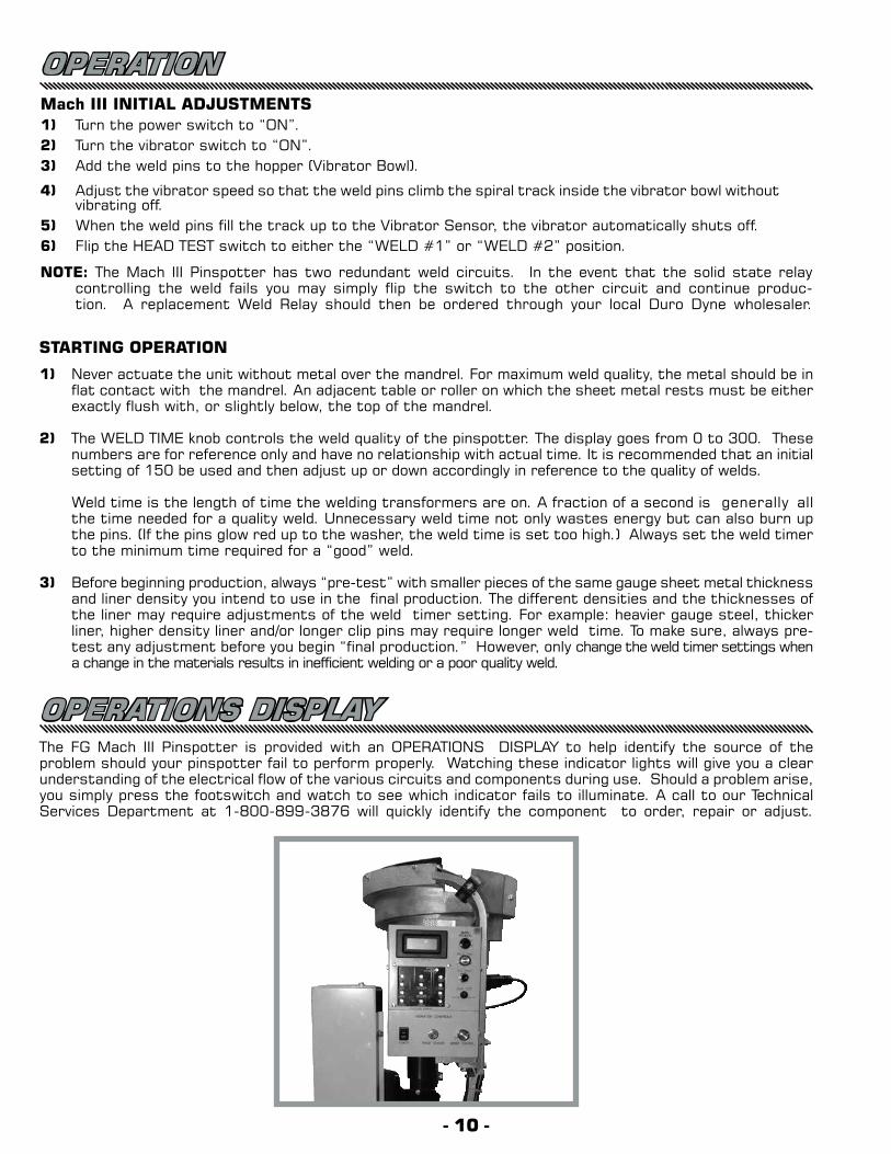
OPERATIONS DISPLAYThe FG Mach III Pinspotter is provided with an OPERATIONS DISPLAY to help identify the source of the problem should your pinspotter fail to perform properly. Watching these indicator lights will give you a clear understanding of the electrical flow of the various circuits and components during use. Should a problem arise, you simply press the footswitch and watch to see which indicator fails to illuminate. A call to our Technical Services Department at 1-800-899-3876 will quickly identify the component to order, repair or adjust.
STARTING OPERATION
1) Never actuate the unit without metal over the mandrel. For maximum weld quality, the metal should be in flat contact with the mandrel. An adjacent table or roller on which the sheet metal rests must be either exactly flush with, or slightly below, the top of the mandrel.
2) The WELD TIME knob controls the weld quality of the pinspotter. The display goes from 0 to 300. These numbers are for reference only and have no relationship with actual time. It is recommended that an initial setting of 150 be used and then adjust up or down accordingly in reference to the quality of welds.
Weld time is the length of time the welding transformers are on. A fraction of a second is generally all the time needed for a quality weld. Unnecessary weld time not only wastes energy but can also burn up the pins. (If the pins glow red up to the washer, the weld time is set too high.) Always set the weld timer to the minimum time required for a “good” weld.
3) Before beginning production, always “pre-test” with smaller pieces of the same gauge sheet metal thickness and liner density you intend to use in the final production. The different densities and the thicknesses of the liner may require adjustments of the weld timer setting. For example: heavier gauge steel, thicker liner, higher density liner and/or longer clip pins may require longer weld time. To make sure, always pre-test any adjustment before you begin “final production.” However, only change the weld timer settings when a change in the materials results in inefficient welding or a poor quality weld.
- 11 -
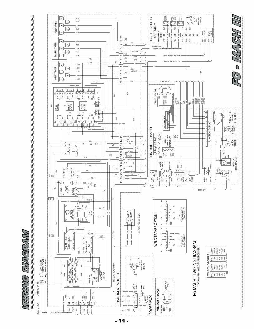
WIR
ING
DIA
GR
AM
FG
- M
AC
H I
II
BOA
RDRE
LAY
SHO
RTCY
CLE
PULS
EFI
RST
18/2
CA
BLE
(YEL
LOW
BA
ND
)
B.C.
B.C.
VIBR
ATO
R BA
SEVI
BRAT
OR
GRN
PLU
G
WEL
DCA
BLE
POW
ER P
ACK
WEL
DTR
AN
SF
BAR
COPP
ER
VIBR
ATO
RCO
IL
RECE
PTRED
BLK
FOO
TSW
ITCH
GRN
BLK
BLK
WEL
DLA
MP
LATE
ST: 2
-24-
16
COM
PON
ENT
MO
DU
LE
3 COND CABLE
RED
BLK
RED
RED
TB2627 25
BLK
BLK
RED
GRN
BLK
WH
T30 29 28
18/2
CA
BLE
(BLA
CK B
AN
D)
240v
208v
SWIT
CHVO
LTAG
E
YEL
RED
YEL
220vSU
PPLY
(6G
A)
PHA
SE P
OW
ER22
0v S
ING
LE
CON
TAC
TOR
24v
COIL
L2
BLK
BLK
WH
TG
RN
L1
T2 T1RE
D WEL
D R
ELAY
#2
3/A
1
4/A
2
2/T1
1/L1
BLK
GRYBLK/RED
BLK/YEL
3/A
1
BLK
WEL
D R
ELAY
4/A
2#1
2/T1
1/L1
RED
ORG RE
DBL
K
YEL
RED
BLU
WHT/GRN
WHT/YEL
WHT/BLU
BLU
WHT/VIO
MA
INPO
WER
BRN
ORN
WEL
D#1
RED
VIBR
ATO
RPO
WER
SW
ITCH
BLK
WH
T
YEL
HEA
DTE
ST
WEL
D
FEED
WEL
D#2
GRN
16/3 CABLE
PIN
POT
BLU
FUSE
2AM
PBL
K
220V
ON
OU
TLET
OFF
WH
T
BLK
20/6CABLE
WHT
A3
RED
GRN
BLK B5
BLKREDA
1B4
2A4B
OFF
TRAC
KSE
NSO
RPO
TVI
BRAT
OR
VIBR
ATO
R
CON
TRO
LSP
EED
INPU
T
DIG
ITA
L D
ISPL
AY
RED
WH
T
RED
CON
NEC
TOR
TO D
ISPL
AY
5 PI
N BLK
FUN
CTI
ON
DIS
PLAY
BLK
WHT
3B1A
ON
AB
12
BLK
BLK
RED9v
dc
ORN
BRN
BLK
RED
1
B.C.
RED
RED
12G
4
WH
TRE
D
Hi
4 52
76
910
811
YEL
21
3
3
4
BLU
5 1
54
CON
SOLE RE
CEIV
ER B
D
BC
A
5Lo
GH
FE
DTB1
RED
TRA
NSF
-2
21T10
1K,2
W
WHT
T3
T1
RED
RED
BLK
WHT/BRNRED
BLK
T11 T9
VIB
CNTR
LRE
LAY
BRD
WH
T
T2
GRNB.C.
B.C.
B.C.
T5TBGRN
B.C.
GRN
WHT
REDYEL
BLU
WHT 2322
24
+V12
VDC
POW
ER
BLK
SUPP
LY
-V
NL
RED
ORG
BLK
RED
1317
GRNGRN
YELBLU
ORGRED
GRN
RED
1920
18
WHT 47KYEL B.C.
RED
1516
14
TRA
NSF
-1
ORN
NO
NC
NOC C
WHTRED
12
K2 1R
TB4
TB9
BRNORG
1R6
1R7
1R8
C
NC
NO
NCC
NO
NC
K1
TB2
TB1
1R1
1R3
1R2
1R4
TB3
1R5
FG M
ACH
-III W
IRIN
G D
IAG
RAM
GRY
GRA
YRE
DRE
D=
BUTT
CO
NN
ECTO
RSB.
C.
WIR
E CO
LOR
CHA
RT
RED
SYM
YEL
BLK
GRN
WH
T
WH
TG
RYBL
KG
RNBR
NO
RN YEL
BLUVI
O
BLK/
RED
BLK/
YEL
WH
T/G
RYW
HT/
BLU
WH
T/G
RN
WH
T/BL
KW
HT/
RED
WH
T/YE
L
WH
T/VI
O
GRE
ENBL
ACK
WH
ITE
YELL
OW
COLO
R
SEN
SOR
RED
LED
LED
BLK
RCVR
EMIT
TER
TRAC
K GRN
WH
TW
HT/
BRN
BRN 20/20 CABLE
18/2 CABLE (RED BAND)
B.C.
VIO
BLU
BRN
SYM
ORN
COLO
RO
RAN
GE
VIO
LET
BRO
WN
BLU
E
WHT/GRYRED
B.C.
WHT/RED
REDVIO
BLU
YEL
FEED
ASS
EMBL
Y
18/2 CABLE (BLUE BAND)
35 36 3837BL
K
RED
GRN
RED
RED
BLU
BLK
BLK
RED
DW
ELL
STRI
PH
EAD
TER
M
31 33 3432
BLK WH
T
WHT/BLK
20/6 CABLE(GREEN BAND)
BLK
BLU
YEL
BLK&
RED
BLK
RED
REED
FEED
DW
ELL
REED
PULS
EFI
RST
REED
DW
ELL
TIM
ER
1WEL
D T
IMER
WHT
2R
TB8
RED
2R6
2R7
2R8
ORG
212R
TB10
C NO
NC
C NO
BLU
YEL 12
TB6
TB5
TB7
2R1
2R4
2R3
2R2
1RWH
T
2R5
NC
NO
C NC
C NO
WHT
NC
WHT
BRN
GRN
RED
BRN
BLK 82K
89
1011
YEL
REDBLU
BLK
YEL
WHT
64
57
4
53
21
35
FEED
TIM
ER
GRN
WHT
BRN
GRN
TB 82K
13
ORN2
42
5
RED
BLK
1
3
2 BLK
4 RED
HM
HM
LL
WEL
D T
RAN
SF O
PTIO
N
END
TO
EN
DH
IGH
OU
TPU
TLO
W O
UTP
UT
END
TO
MID
DLE
(7KV
A/6
0AM
P W
ELD
TRA
NSF
ORM
ER)
C
YEL
WHT
BLK
RED
BLU
WH
T
BLK
RED
BLU
31
YEL
B229
-01-
40/
RED
BLK
BLK
RED
FEED
SOLE
N
DW
ELL
SOLE
N
4039
CON
TRO
L
PRES
SURE
SWIT
CH
- 12 -
MAINTENANCE1) To prolong the weld tip life and improve the weld quality, it is imperative that the weld tips always be kept
clean. For best results, use a solvent to remove any built-up adhesive; a wire brush to remove any galva-nizing deposits; and a fine emory cloth to smooth the tip surfaces.
2) When the lower weld tip becomes worn in one area, loosen the locking cap screw and rotate the point of wear away from the point of contact. If this cannot be done because the lower weld tip is too badly pitted, replace the lower weld tip plate. Loosen set screw in weld tip shaft. remove 2 slotted screws.Assemble new weld plate in reverse order. Additional lower weld tip plates can be ordered from your local distributor.
3) Depending on usage and maintenance, the upper welding tip plate will have to be periodically replaced. The replacement weld tip plates can be ordered from your local distributor. To replace the upper weld tip, loosen the locking cap screw and remove the weld tip. To replace the plate remove the three (3) brass screws. Discard the screws and attach the new plate to the tip using the three brass screws supplied. Be sure to align the angled section of the plate so it faces the feed mechanism. Then lock the tip in place. Cycle the machine to check the feeding.
4) If the feeding is erratic, re-adjust the upper weld tip height by loosening the lock nut and then turning the dwell cylinder shaft clockwise to raise the tip; counter-clockwise to lower the tip. Lock the tip in position with the locking nut.
SERVICINGA SIMPLIFIED STEP-BY-STEP PROCEDURE
Duro Dyne has called upon its many years of pinspotting experience in designing the FG Mach III. Your unit has been rigorously factory tested and inspected to provide many years of dependable service.
WHAT TO DO BEFORE YOU BEGIN TROUBLESHOOTING: CONSULT THE MANUAL.
Most of the functional problems that occur are due to an oversight in the set-up, operational or normal maintenance procedures. Therefore, you should re-check all “Set Up”, “Initial Adjustment”, “Operation” and “Maintenance” procedures.
INSPECT THE UNIT
If the problem still persists, the next step is careful visual inspection. Turn off the electricity - that is, discon-nect your Pinspotter from its power supply and carefully check the control box for loose, broken or disconnected wires. Also check the air circuit for leaky air connections or cut hoses.
HOW TO IDENTIFY WELD QUALITY PROBLEMS
By weld we mean that the Power Pack is energized, sending a pulse of electricity through the weld pin, caus-ing it to begin to fuse to the sheet metal. To properly troubleshoot the weld quality problems, you must first pinpoint the symptom by test welding the clip pins to bare sheet metal. The symptom will then show up in one of four categories:1) The pins weld to bare metal but not on lined work.2) The pins weld to bare metal but can easily be removed.3) Pins weld to bare metal but remain on the weld tip as it retracts.4) The pins do not weld at all.
Before troubleshooting, always check:1) Air pressure for a minimum of 80 PSI during usage of unit.2) The input Voltage for a minimum of 208V and a maximum of 230V.3) The Weld Timer is set properly.4) The Upper and the Lower Weld tips for extreme wear.
It may become necessary to use a voltmeter and/or ohmmeter to perform some servicing procedures. An Analog type is best. Our Technical Services Department will help you if necessary.
- 13 -
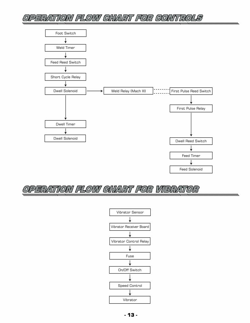
OPERATION FLOW CHART FOR CONTROLS
Foot Switch
Weld Timer
Feed Reed Switch
Short Cycle Relay
Dwell Solenoid
Dwell Timer
Dwell Solenoid
Weld Relay (Mach III) First Pulse Reed Switch
First Pulse Relay
Dwell Reed Switch
Feed Timer
Feed Solenoid
Vibrator Sensor
Vibrator Receiver Board
Vibrator Control Relay
Fuse
On/Off Switch
Speed Control
Vibrator
OPERATION FLOW CHART FOR VIBRATOR
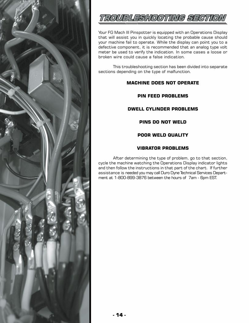
TROUBLESHOOTING SECTION Your FG Mach III Pinspotter is equipped with an Operations Display that will assist you in quickly locating the probable cause should your machine fail to operate. While the display can point you to a defective component, it is recommended that an analog type volt meter be used to verify the indication. In some cases a loose or broken wire could cause a false indication.
This troubleshooting section has been divided into separate sections depending on the type of malfunction.
MACHINE DOES NOT OPERATE
PIN FEED PROBLEMS
DWELL CYLINDER PROBLEMS
PINS DO NOT WELD
POOR WELD QUALITY
VIBRATOR PROBLEMS
After determining the type of problem, go to that section, cycle the machine watching the Operations Display indicator lights and then follow the instructions in that part of the chart. If further assistance is needed you may call Duro Dyne Technical Services Depart-ment at 1-800-899-3876 between the hours of 7am - 6pm EST.
- 14 -
- 15 -
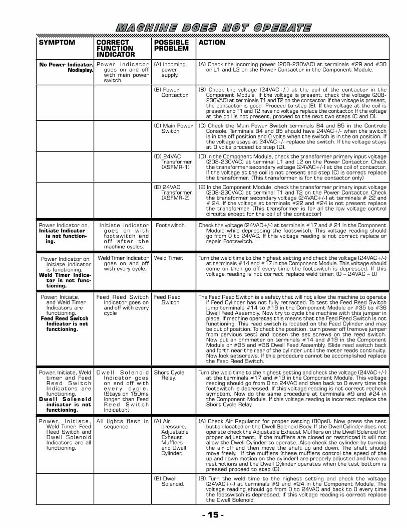
M A C H I N E D O E S N O T O P E R AT ESYMPTOM CORRECT
FUNCTION INDICATOR
POSSIBLEPROBLEM
ACTION
No Power Indicator.No display.
Power Ind icator goes on and off with main power switch.
(A) Incoming power supply.
(A) Check the incoming power (208-230VAC) at terminals #29 and #30 or L1 and L2 on the Power Contactor in the Component Module.
(B) Power Contactor.
(B) Check the voltage (24VAC+/-) at the coil of the contactor in the Component Module. If the voltage is present, check the voltage (208-230VAC) at terminals T1 and T2 on the contactor. If the voltage is present, the contactor is good. Proceed to step (E). If the voltage at the coil is present and T1 and T2 have no voltage replace the contactor. If the voltage at the coil is not present, proceed to the next two steps (C and D).
(C) Main Power Switch.
(C) Check the Main Power Switch terminals B4 and B5 in the Controle Console. Terminals B4 and B5 should have 24VAC+/- when the switch is in the off position and 0 volts when the switch is in the on position. If the voltage stays at 24VAC+/- replace the switch. If the voltage stays at 0 volts proceed to step (D).
(D) 24VAC Transformer.
(XSFMR-1)
(D) In the Component Module, check the transformer primary input voltage (208-230VAC) at terminal L1 and L2 on the Power Contactor. Check the transformer secondary voltage (24VAC+/-) at the coil of contactor. If the voltage at the coil is not present and step (C) is correct replace the transformer. (This transformer is for the contactor only)
(E) 24VAC Transformer.
(XSFMR-2)
(E) In the Component Module, check the transformer primary input voltage (208-230VAC) at terminal T1 and T2 on the Power Contactor. Check the transformer secondary voltage (24VAC+/-) at terminals # 22 and # 24. If the voltage at terminals #22 and #24 is not present replace the transformer. (This transformer is for all the low voltage control circuits except for the coil of the contactor)
Power Indicator on.Initiate Indicator
is not function-ing.
Initiate Indicator goes on w i th footswitch and o f f a f t e r the machine cycles.
Footswitch. Check the voltage (24VAC+/-) at terminals #17 and # 21 in the Component Module while depressing the footswitch. This voltage reading should go from 0 to 24VAC. If this voltage reading is not correct replace or repair Footswitch.
Power Indicator on. Initiate indicator is functioning.
Weld Timer Indica-tor is not func-tioning.
Weld Timer Indicator goes on and off with every cycle.
Weld Timer. Turn the weld time to the highest setting and check the voltage (24VAC+/-) at terminals #14 and #17 in the Component Module. This voltage should come on then go off every time the footswitch is depressed. If this voltage reading is not correct replace weld timer. (0 – 24VAC – 0)
Power, Initiate, and Weld Timer Indicators are functioning.
Feed Reed Switch Indicator is not functioning.
Feed Reed Switch Indicator goes on and off with every cycle
Feed Reed Switch.
The Feed Reed Switch is a safety that will not allow the machine to operate if Feed Cylinder has not fully retracted. To test the Feed Reed Switch jump terminals #14 to #19 in the Component Module or #35 to #36 Dwell Feed Assembly. Now try to cycle the machine with this jumper in place. If machine operates this means that the Feed Reed Switch is not functioning. This reed switch is located on the Feed Cylinder and may be out of position. To check the position, turn power off (remove jumper from pervious test) and loosen the set screws on the reed switch. Now put an ohmmeter on terminals #14 and #19 in the Component Module or #35 and #36 Dwell Feed Assembly. Slide reed switch back and forth near the rear of the cylinder until the meter reads continuity. Now lock setscrews. If this procedure cannot be accomplished replace the Feed Reed Switch.
Power, Initiate, Weld timer and Feed R e e d S w i t c h Indicators are functioning.
Dwe l l S o l e no i d indicator is not functioning.
D w e l l S o l e n o i d Indicator goes on and off with e v e r y c y c l e . (Stays on 150ms longer than Feed R e e d S w i t c h Indicator.)
Short Cycle Relay.
Turn the weld time to the highest setting and check the voltage (24VAC+/-) at the terminals #17 and #19 in the Component Module. This voltage reading should go from 0 to 24VAC and then back to 0 every time the footswitch is depressed. If this voltage reading is not correct recheck symptom. Now do the same procedure at terminals #9 and #24 in the Component Module. If this voltage reading is incorrect replace the Short Cycle Relay.
Power, I n i t i a te , Weld Timer, Feed Reed Switch and Dwell Solenoid Indicators are all functioning.
All lights flash in sequence.
(A) Air pressure,Adjustable ExhaustMufflers and Dwell Cylinder.
(A) Check Air Regulator for proper setting (80psi). Now press the test button located on the Dwell Solenoid Body. If the Dwell Cylinder does not operate check the Adjustable Exhaust Mufflers on the Dwell Solenoid for proper adjustment. If the mufflers are closed or restricted it will not allow the Dwell Cylinder to operate. Also check the cylinder by turning the air off and then move the shaft up and down. The shaft should move freely. If the mufflers (these mufflers control the speed of the up and down motion on the cylinder) are properly adjusted and have no restrictions and the Dwell Cylinder operates when the test bottom is pressed proceed to step (B).
(B) Dwell Solenoid.
(B) Turn the weld time to the highest setting and check the voltage (24VAC+/-) at terminals #9 and #24 in the Component Module. The voltage reading should go from 0 to 24VAC and back to 0 every time the footswitch is depressed. If this voltage reading is correct replace the Dwell Solenoid.
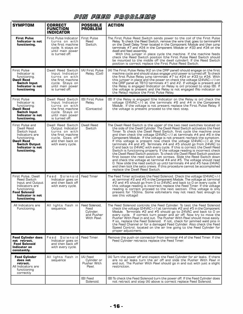
P I N F E E D P R O B L E M SSYMPTOM CORRECT
FUNCTION INDICATOR
POSSIBLEPROBLEM
ACTION
First Pulse Indicator is not functioning.
First Pulse Indicator turns on with the first machine cycle. It stays on until main power is turned off.
First Pulse Reed Switch.
The First Pulse Reed Switch sends power to the coil of the First Pulse Relay. To check the Reed Switch, remove the wire that goes to terminal#4 on the Dwell Delay Timer located in the Component Module and then jump terminals #7 and #24 in the Component Module or #33 and #34 on the dwell and feed assembly.
With this jumper in place cycle the machine. If the machine feeds check the Reed Switch position (the First Pulse Reed Switch should be mounted to the middle off the dwell cylinder). If the Reed Switch position is correct replace the First Pulse Reed Switch.
First Pulse Indicator is functioning.
Dwell Reed Switch Input Indicator is not functioning
Dwell Reed Switch Input Indicator turns on with the first machine cycle. Stays on until main power is turned off.
(A) First Pulse Relay. (Coil)
(A) The First Pulse Relay (K2 on the DRP panel) should engage on the first machine cycle and should stays engage until power is turned off. To check the first Pulse Relay jump terminals #7 to #24 or #33 to #34. With this jumper in place and the power on check the voltage (24VAC+/-) on the DRP panel at TB10 terminals #1 and #2. If voltage is present and the Relay is engaged (Indicator on Relay is on) proceed to step (B). If the voltage is present and the Relay is not engaged (No indicator on the Relay) replace the First Pulse Relay.
First Pulse Indicator is functioning.
Dwell Reed Switch Input Indicator is not functioning.
Dwell Reed Switch Input Indicator turns on with the first machine cycle. Stays on until main power is turned off.
(B) First Pulse Relay.
(Contacts)
(B) If the Relay is engaged (the Indicator on the Relay is on) check the voltage (24VAC+/-) at the terminals #6 and #4 in the Component Module . If the voltage is not present replace the First Pulse Relay. If the voltage is present proceed to the next step.
First Pulse and Dwell Reed Switch Input Indicators are functioning.
Dwell Reed Switch Output Indicator is not functioning.
Dwell Reed Switch Output Indicator turns on with the first machine cycle. Goes off and then back on with every cycle.
Dwell Reed Switch
The Dwell Reed Switch is the upper of the two reed switches located on the side of the Dwell Cylinder. The Dwell Reed Switch activates the Feed Timer. To check the Dwell Reed Switch, first cycle the machine once and then check the voltage (24VAC+/-) at terminals #4 and #6 in the Component Module . If the voltage is not present recheck the symptom. If this voltage is present now check the voltage (24VAC+/-) at the terminals #4 and #5. Terminals #4 and #5 should go from 24VAC to 0 and back to 24VAC with every cycle. If this is correct the Dwell Reed Switch is functioning properly. If the voltage reading is incorrect check the Dwell Reed Switch position. To check the Dwell Reed Switch position first loosen the reed switch set screws. Slide the Reed Switch down and check the voltage at terminal #4 and #5. The voltage should read 0. Now slide the reed switch up until terminals #4 and #5 have 24VAC and then lock the sets crews. If this procedure cannot be accomplished replace the Dwell Reed Switch.
First Pulse, Dwell Reed Switch Input and Output Indicators are functioning.
Feed Solenoid Indicator is not functioning
F e e d S o l e n o i d Indicator goes on and then back off with every cycle.
Feed Timer The Feed Timer activates the Feed Solenoid. Check the voltage (24VAC+/-) at terminal #2 and #5 in the Component Module. The voltage at terminal #2 and #5 should go from 0 to 24VAC and back to 0 on every cycle. If this voltage reading is incorrect replace the Feed Timer. If the voltage reading is correct proceed to the next section. (This voltage is only present for 150ms. Some voltmeters may not react fast enough to see this voltage)
All Indicators are Functioning.
All lights flash in sequence.
Feed Solenoid, Feed
Cylinder, and Pusher With Pawl.
The Feed Solenoid controls the Feed Cylinder. To test the Feed Solenoid check the voltage (24VAC+/-) at terminals #2 and #5 in the Component Module. Terminals #2 and #5 should go to 24VAC and back to 0 on every cycle. If correct turn power and air off. Now try to move the Pusher With Pawl in and out. The Pusher With Pawl should move easily. If so, replace the Feed Solenoid. If not, check for jammed weld pins in the Feed Channel or for a damaged Feed Cylinder. Also check the Feed Speed Control, located on the air line going to the Feed Cylinder for proper adjustment.
Feed Cylinder does not retract. Feed Solenoid Indicator on constantly.
F e e d S o l e n o i d Indicator goes on and then back off with every cycle.
Feed Timer. Remove the push-on connector from terminal #4 of the Feed Timer. If the Feed Cylinder retracts replace the Feed Timer.
Feed Cylinder does not retract.
All Indicators are functioning correctly
All lights flash in sequence
(A) Feed Cylinder or
Pusher With Pawl.
(A) Turn the power off and inspect the Feed Cylinder for air leaks. If there are no air leaks turn the air off and slide the Pusher With Pawl in and out. The Pusher With Pawl should go in and out with just a slight restriction.
(B) Feed Solenoid.
(B) To check the Feed Solenoid turn the power off. If the Feed Cylinder does not retract and step (A) above is correct replace Feed Solenoid.
- 16 -
- 17 -
SYMPTOM CORRECT FUNCTION INDICATOR
POSSIBLEPROBLEM
ACTION
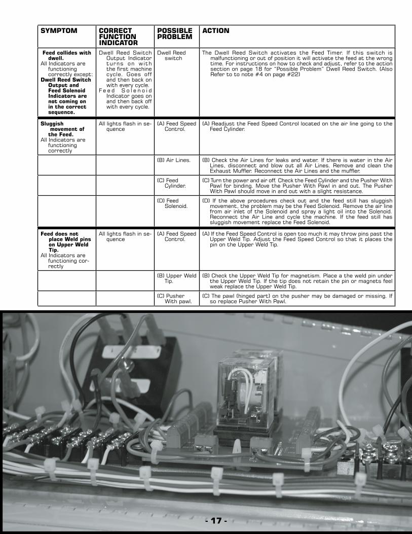
Feed collides with dwell.
All Indicators are functioning correctly except:
Dwell Reed Switch Output and Feed Solenoid Indicators are not coming on in the correct sequence.
Dwell Reed Switch Output Indicator turns on with the first machine cycle. Goes off and then back on with every cycle.
F e e d S o l e n o i d Indicator goes on and then back off with every cycle.
Dwell Reed switch
The Dwell Reed Switch activates the Feed Timer. If this switch is malfunctioning or out of position it will activate the feed at the wrong time. For instructions on how to check and adjust, refer to the action section on page 18 for “Possible Problem” Dwell Reed Switch. (Also Refer to to note #4 on page #22)
Sluggish movement of
the Feed.All Indicators are
functioning correctly
All lights flash in se-quence
(A) Feed Speed Control.
(A) Readjust the Feed Speed Control located on the air line going to the Feed Cylinder.
(B) Air Lines. (B) Check the Air Lines for leaks and water. If there is water in the Air Lines, disconnect and blow out all Air Lines. Remove and clean the Exhaust Muffler. Reconnect the Air Lines and the muffler.
(C) Feed Cylinder.
(C) Turn the power and air off. Check the Feed Cylinder and the Pusher With Pawl for binding. Move the Pusher With Pawl in and out. The Pusher With Pawl should move in and out with a slight resistance.
(D) Feed Solenoid.
(D) If the above procedures check out and the feed still has sluggish movement, the problem may be the Feed Solenoid. Remove the air line from air inlet of the Solenoid and spray a light oil into the Solenoid. Reconnect the Air Line and cycle the machine. If the feed still has sluggish movement replace the Feed Solenoid.
Feed does not place Weld pins on Upper Weld Tip.
All Indicators are functioning cor-rectly
All lights flash in se-quence
(A) Feed Speed Control.
(A) If the Feed Speed Control is open too much it may throw pins past the Upper Weld Tip. Adjust the Feed Speed Control so that it places the pin on the Upper Weld Tip.
(B) Upper Weld Tip.
(B) Check the Upper Weld Tip for magnetism. Place a the weld pin under the Upper Weld Tip. If the tip does not retain the pin or magnets feel weak replace the Upper Weld Tip.
(C) Pusher With pawl.
(C) The pawl (hinged part) on the pusher may be damaged or missing. If so replace Pusher With Pawl.
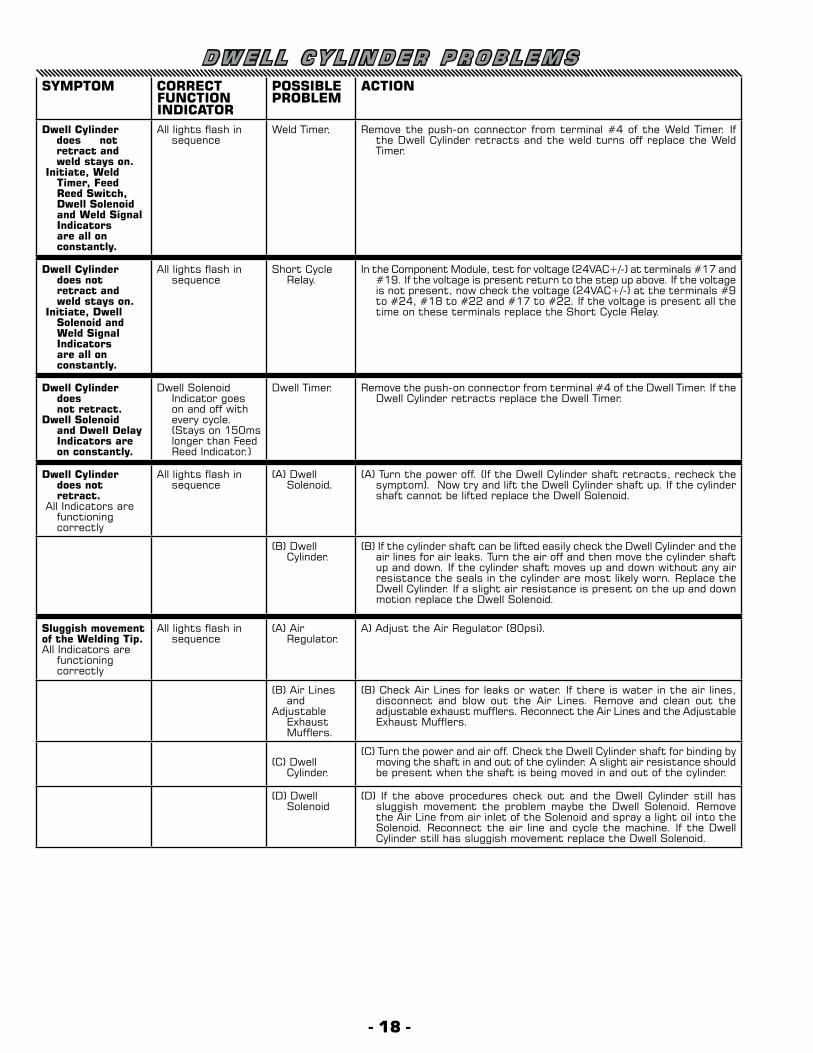
D W E L L C Y L I N D E R P R O B L E M SSYMPTOM CORRECT
FUNCTION INDICATOR
POSSIBLEPROBLEM
ACTION
Dwell Cylinder does not retract and weld stays on.
Initiate, Weld Timer, Feed Reed Switch, Dwell Solenoid and Weld Signal Indicators are all on constantly.
All lights flash in sequence
Weld Timer. Remove the push-on connector from terminal #4 of the Weld Timer. If the Dwell Cylinder retracts and the weld turns off replace the Weld Timer.
Dwell Cylinder does not retract and weld stays on.
Initiate, Dwell Solenoid and Weld Signal Indicators are all on constantly.
All lights flash in sequence
Short Cycle Relay.
In the Component Module, test for voltage (24VAC+/-) at terminals #17 and #19. If the voltage is present return to the step up above. If the voltage is not present, now check the voltage (24VAC+/-) at the terminals #9 to #24, #18 to #22 and #17 to #22. If the voltage is present all the time on these terminals replace the Short Cycle Relay.
Dwell Cylinder does
not retract.Dwell Solenoid
and Dwell Delay Indicators are on constantly.
Dwell Solenoid Indicator goes on and off with every cycle. (Stays on 150ms longer than Feed Reed Indicator.)
Dwell Timer. Remove the push-on connector from terminal #4 of the Dwell Timer. If the Dwell Cylinder retracts replace the Dwell Timer.
Dwell Cylinder does not retract.
All Indicators are functioning correctly
All lights flash in sequence
(A) Dwell Solenoid.
(A) Turn the power off. (If the Dwell Cylinder shaft retracts, recheck the symptom). Now try and lift the Dwell Cylinder shaft up. If the cylinder shaft cannot be lifted replace the Dwell Solenoid.
(B) Dwell Cylinder.
(B) If the cylinder shaft can be lifted easily check the Dwell Cylinder and the air lines for air leaks. Turn the air off and then move the cylinder shaft up and down. If the cylinder shaft moves up and down without any air resistance the seals in the cylinder are most likely worn. Replace the Dwell Cylinder. If a slight air resistance is present on the up and down motion replace the Dwell Solenoid.
Sluggish movement of the Welding Tip.All Indicators are
functioning correctly
All lights flash in sequence
(A) Air Regulator.
A) Adjust the Air Regulator (80psi).
(B) Air Lines and
Adjustable Exhaust Mufflers.
(B) Check Air Lines for leaks or water. If there is water in the air lines, disconnect and blow out the Air Lines. Remove and clean out the adjustable exhaust mufflers. Reconnect the Air Lines and the Adjustable Exhaust Mufflers.
(C) Dwell Cylinder.
(C) Turn the power and air off. Check the Dwell Cylinder shaft for binding by moving the shaft in and out of the cylinder. A slight air resistance should be present when the shaft is being moved in and out of the cylinder.
(D) Dwell Solenoid
(D) If the above procedures check out and the Dwell Cylinder still has sluggish movement the problem maybe the Dwell Solenoid. Remove the Air Line from air inlet of the Solenoid and spray a light oil into the Solenoid. Reconnect the air line and cycle the machine. If the Dwell Cylinder still has sluggish movement replace the Dwell Solenoid.
- 18 -
- 19 -
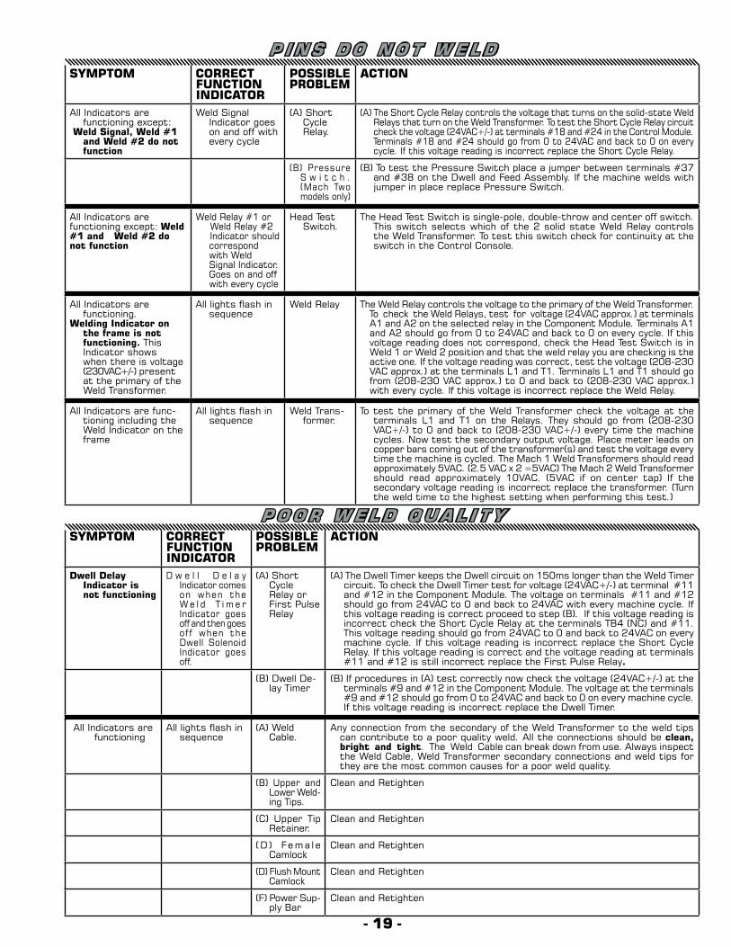
P I N S D O N O T W E L D
P O O R W E L D Q U A L I T Y
SYMPTOM CORRECT FUNCTION INDICATOR
POSSIBLEPROBLEM
ACTION
All Indicators are functioning except:
Weld Signal, Weld #1 and Weld #2 do not function
Weld Signal Indicator goes on and off with every cycle
(A) Short Cycle Relay.
(A) The Short Cycle Relay controls the voltage that turns on the solid-state Weld Relays that turn on the Weld Transformer. To test the Short Cycle Relay circuit check the voltage (24VAC+/-) at terminals #18 and #24 in the Control Module. Terminals #18 and #24 should go from 0 to 24VAC and back to 0 on every cycle. If this voltage reading is incorrect replace the Short Cycle Relay.
(B) Pressure S w i t c h . (Mach Two models only)
(B) To test the Pressure Switch place a jumper between terminals #37 and #38 on the Dwell and Feed Assembly. If the machine welds with jumper in place replace Pressure Switch.
All Indicators are functioning except: Weld #1 and Weld #2 do not function
Weld Relay #1 orWeld Relay #2Indicator should correspond with Weld Signal Indicator.Goes on and off with every cycle
Head Test Switch.
The Head Test Switch is single-pole, double-throw and center off switch. This switch selects which of the 2 solid state Weld Relay controls the Weld Transformer. To test this switch check for continuity at the switch in the Control Console.
All Indicators are functioning.
Welding Indicator on the frame is not functioning. This Indicator shows when there is voltage (230VAC+/-) present at the primary of the Weld Transformer.
All lights flash in sequence
Weld Relay The Weld Relay controls the voltage to the primary of the Weld Transformer. To check the Weld Relays, test for voltage (24VAC approx.) at terminals A1 and A2 on the selected relay in the Component Module. Terminals A1 and A2 should go from 0 to 24VAC and back to 0 on every cycle. If this voltage reading does not correspond, check the Head Test Switch is in Weld 1 or Weld 2 position and that the weld relay you are checking is the active one. If the voltage reading was correct, test the voltage (208-230 VAC approx.) at the terminals L1 and T1. Terminals L1 and T1 should go from (208-230 VAC approx.) to 0 and back to (208-230 VAC approx.) with every cycle. If this voltage is incorrect replace the Weld Relay.
All Indicators are func-tioning including the Weld Indicator on the frame
All lights flash in sequence
Weld Trans-former.
To test the primary of the Weld Transformer check the voltage at the terminals L1 and T1 on the Relays. They should go from (208-230 VAC+/-) to 0 and back to (208-230 VAC+/-) every time the machine cycles. Now test the secondary output voltage. Place meter leads on copper bars coming out of the transformer(s) and test the voltage every time the machine is cycled. The Mach 1 Weld Transformers should read approximately 5VAC. (2.5 VAC x 2 =5VAC) The Mach 2 Weld Transformer should read approximately 10VAC. (5VAC if on center tap) If the secondary voltage reading is incorrect replace the transformer. (Turn the weld time to the highest setting when performing this test.)
SYMPTOM CORRECT FUNCTION INDICATOR
POSSIBLEPROBLEM
ACTION
Dwell Delay Indicator is not functioning
D w e l l D e l a y Indicator comes on when the W e l d T i m e r Indicator goes off and then goes off when the Dwell Solenoid Indicator goes off.
(A) Short Cycle Relay or First Pulse Relay
(A) The Dwell Timer keeps the Dwell circuit on 150ms longer than the Weld Timer circuit. To check the Dwell Timer test for voltage (24VAC+/-) at terminal #11 and #12 in the Component Module. The voltage on terminals #11 and #12 should go from 24VAC to 0 and back to 24VAC with every machine cycle. If this voltage reading is correct proceed to step (B). If this voltage reading is incorrect check the Short Cycle Relay at the terminals TB4 (NC) and #11. This voltage reading should go from 24VAC to 0 and back to 24VAC on every machine cycle. If this voltage reading is incorrect replace the Short Cycle Relay. If this voltage reading is correct and the voltage reading at terminals #11 and #12 is still incorrect replace the First Pulse Relay.
(B) Dwell De-lay Timer
(B) If procedures in (A) test correctly now check the voltage (24VAC+/-) at the terminals #9 and #12 in the Component Module. The voltage at the terminals #9 and #12 should go from 0 to 24VAC and back to 0 on every machine cycle. If this voltage reading is incorrect replace the Dwell Timer.
All Indicators are functioning
All lights flash in sequence
(A) Weld Cable.
Any connection from the secondary of the Weld Transformer to the weld tips can contribute to a poor quality weld. All the connections should be clean, bright and tight. The Weld Cable can break down from use. Always inspect the Weld Cable, Weld Transformer secondary connections and weld tips for they are the most common causes for a poor weld quality.
(B) Upper and Lower Weld-ing Tips.
Clean and Retighten
(C) Upper Tip Retainer.
Clean and Retighten
(D ) Fema l e Camlock
Clean and Retighten
(D) Flush Mount Camlock
Clean and Retighten
(F) Power Sup-ply Bar
Clean and Retighten
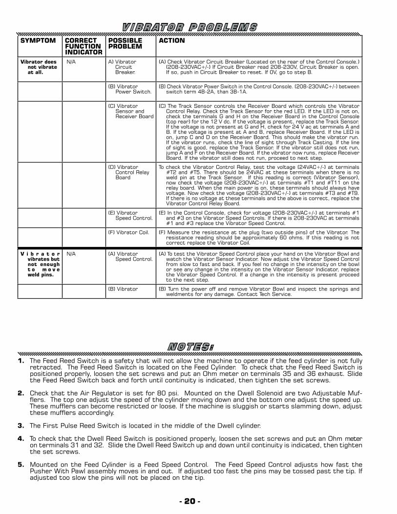
N O T E S :1. The Feed Reed Switch is a safety that will not allow the machine to operate if the feed cylinder is not fully
retracted. The Feed Reed Switch is located on the Feed Cylinder. To check that the Feed Reed Switch is positioned properly, loosen the set screws and put an Ohm meter on terminals 35 and 36 exhaust. Slide the Feed Reed Switch back and forth until continuity is indicated, then tighten the set screws.
2. Check that the Air Regulator is set for 80 psi. Mounted on the Dwell Solenoid are two Adjustable Muf-flers. The top one adjust the speed of the cylinder moving down and the bottom one adjust the speed up. These mufflers can become restricted or loose. If the machine is sluggish or starts slamming down, adjust these mufflers accordingly.
3. The First Pulse Reed Switch is located in the middle of the Dwell cylinder.
4. To check that the Dwell Reed Switch is positioned properly, loosen the set screws and put an Ohm meter on terminals 31 and 32. Slide the Dwell Reed Switch up and down until continuity is indicated, then tighten the set screws.
5. Mounted on the Feed Cylinder is a Feed Speed Control. The Feed Speed Control adjusts how fast the Pusher With Pawl assembly moves in and out. If adjusted too fast the pins may be tossed past the tip. If adjusted too slow the pins will not be placed on the tip.
SYMPTOM CORRECT FUNCTION INDICATOR
POSSIBLEPROBLEM
ACTION
Vibrator does not vibrate at all.
N/A A) Vibrator Circuit Breaker.
(A) Check Vibrator Circuit Breaker (Located on the rear of the Control Console.) (208-230VAC+/-) If Circuit Breaker read 208-230V, Circuit Breaker is open.If so, push in Circuit Breaker to reset. If 0V, go to step B.
(B) Vibrator Power Switch.
(B) Check Vibrator Power Switch in the Control Console. (208-230VAC+/-) between switch term 4B-2A, than 3B-1A.
(C) Vibrator Sensor and Receiver Board
(C) The Track Sensor controls the Receiver Board which controls the Vibrator Control Relay. Check the Track Sensor for the red LED. If the LED is not on, check the terminals G and H on the Receiver Board in the Control Console (top rear) for the 12 V dc. If the voltage is present, replace the Track Sensor. If the voltage is not present at G and H, check for 24 V ac at terminals A and B. If the voltage is present at A and B, replace Receiver Board. If the LED is on, jump C and D on the Receiver Board. This should make the vibrator run. If the vibrator runs, check the line of sight through Track Casting. If the line of sight is good, replace the Track Sensor. If the vibrator still does not run, jump A and F on the Receiver Board. If the vibrator now runs, replace Receiver Board. If the vibrator still does not run, proceed to next step.
(D) Vibrator Control Relay Board
To check the Vibrator Control Relay, test the voltage (24VAC+/-) at terminals #T2 and #T5. There should be 24VAC at these terminals when there is no weld pin at the Track Sensor. If this reading is correct (Vibrator Sensor), now check the voltage (208-230VAC+/-) at terminals #T1 and #T11 on the relay board. When the main power is on, these terminals should always have voltage. Now check the voltage (208-230VAC+/-) at terminals #T3 and #T9. If there is no voltage at these terminals and the above is correct, replace the Vibrator Control Relay Board.
(E) Vibrator Speed Control.
(E) In the Control Console, check for voltage (208-230VAC+/-) at terminals #1 and #3 on the Vibrator Speed Controls. If there is 208-230VAC at terminals #1 and #3 replace the Vibrator Speed Control.
(F) Vibrator Coil. (F) Measure the resistance at the plug (two outside pins) of the Vibrator. The resistance reading should be approximately 60 ohms. If this reading is not correct replace the Vibrator Coil.
V i b r a t o r vibrates but not enough t o m o v e weld pins.
N/A (A) Vibrator Speed Control.
(A) To test the Vibrator Speed Control place your hand on the Vibrator Bowl and watch the Vibrator Sensor Indicator. Now adjust the Vibrator Speed Control from slow to fast and back. If you feel no change in the intensity on the bowl or see any change in the intensity on the Vibrator Sensor Indicator, replace the Vibrator Speed Control. If a change in the intensity is present proceed to the next step.
(B) Vibrator (B) Turn the power off and remove Vibrator Bowl and inspect the springs and weldments for any damage. Contact Tech Service.
V I B R AT O R P R O B L E M S
- 20 -
- 21 -
17084 Air hose 3/8” natural17135 Lift Kit17189 Upper weld tip plates - (5/pkg)17190 Lower weld tip plates - (5/pkg)17191 Upper weld tip17192 Lower weld tip17198 Track casting spacers and screws17203 Fiber insulator17222 Terminal strip - low voltage17236 Dwell Cylinder Bracket17257 Vibrator support casting17260 Upper feed track casting17265 Lower track side rails 17266 Feed channel17269 Feed cylinder bracket17288 Footswitch plug17317 Feed speed control17318 Feed timer17319 Dwell timer17319 Weld timer17323 Short cycle relay17323 First pulse relay17325 Pressure switch17327 Footswitch receptacle17348 Feed channel plate17351 Pusher and pawl17352 Upper tip retainer17356 Adjustable muffler17363 Dwell reed switch17363 First pulse reed switch17363 Feed reed switch17364 Feed cylinder17372 Footswitch17376 Lower mandrel17377 Air regulator17394 Short shaft extension18066 200V Phase Control18065 Vibrator Circuit Breaker (2 Amp)39068 Receiver Board39110 Pin feed switch39196 220V Vibrator Female Cord39273 Vibrator Base Plate39296 Vibrator Bowl Assembly39298 220V Vibrator with cord39306 Incoming Voltage Selector Switch39353 Anti-friction strip
39359 Feed channel spacer40102 Air hose 3/8” blue40105 Air hose 1/4” yellow40106 Air hose 1/4” blue44010 Lower track casting44014 Feed solenoid44019 Weld cable camlock44020 Head terminal strip44022 Lower ground bar44024 Main power switch44025 LCD display44026 Weld potentiometer44027 Weld potentiometer knob44027 Vibrator potentiometer knob44029 Head test switch44030 Troubleshooting LED display44031 Vibrator potentiometer44032 Vibrator lamp44033 Vibrator power switch44034 Weld lamp44041 Line cord44042 Line cord strain relief44045 Weld cable guard44047 Power contactor44051 Relay Board44052 12 volt DC power supply44053 Weld Relay44054 Heat Sink44090 Vibrator Control Relay Board44091 24V Multi-Tap Transformer44095 Track Sensor44101 220V 7KVA MCI Transformer44102 Dwell Cylinder44103 Upper Track Side Rail - Short44104 Upper Track Side Rail - Long44105 Power Pack Tray44106 Power Pack Cover44107 Dwell Cover44108 Feed Cover44109 Control Module44110 Head Mounting Plate44111 Short Weld Cable44113 Component Module44114 Vibrator Strain Relief44115 Hi-Volt Terminator Strip44116 Dwell Solenoid Assembly
PARTS LIST

NOTES

NOTES
MACHINERY DIVISION© 2017 Duro Dyne CorporationPrinted in USA 4/20/2017BI060002
®
FG MACH I I IPlease Visit Our Website
www.durodyne.comfor the most current product information.
Products that may also be of interest to you:
®