ezo tm class embedded ph circuit v 1 ph circuit this is an evolving document ... or double junction...
TRANSCRIPT

pH CircuitEZO TM
Atlas-Scientific.com Copyright © Atlas Scientific LLC All Rights Reserved 1
DescriptionThe Atlas Scientific™ EZO™ class embedded pH circuit, is our 6th generation embedded pH circuit. This EZO class pH circuit, offers the highest level of stability and accuracy. With proper configuration the EZO class pH circuit, can meet, or exceed the accuracy and precision found in most bench top laboratory grade pH meters. The pH-EZO™ pH circuit, can work with any off-the-shelf pH probe/sensor/electrode. This device reads pH from a pH probe/sensor/electrode. This device does not include a pH probe/sensor/electrode.
TM
EZO TM class embedded pH circuit This is an evolving document
check back for updates.
V 1.3
Features• Full range pH reading from .001 to 14.000• Accurate pH readings down to the
thousands place (+/- 0.02)• Temperature dependent or temperature
independent readings• Flexible calibration protocol supports single point,
2 point, or 3 point calibration• Calibration required only once per year with
Atlas Scientific pH probe• Single reading or continuous reading modes• Data format is ASCII
Two data protocols • UART asynchronous serial connectivity• (RX/TX voltage swing 0-VCC)• I2C (default I2C address 0x63)• Compatible with any microprocessor that supports
UART, or I2C protocol• Operating voltage: 3.3V to 5V• Works with any off-the-shelf pH probe
Sleep mode power consumption• 0.995mA at 3.3V
Patent pending

EZO TM
pH Circuit
Contents
UART Mode I2C Mode
System overview .........................Power consumption .................... Pin out .........................................Device operation ......................... Calibration theory .......................Design considerations ................Power and data isolation ............Board mounting ..........................Calibration UART Mode .............. Calibration I2C Mode ..................
UART command quick reference ... L,<1|0|?> .......................................C,<1|0|?> .......................................R .................................................... T,<XX.XX|?> ..................................Cal,<type|nnn> ..............................Name,<nnn|?> ...............................I .....................................................Response,<1|0|?> ..........................Status ............................................ Sleep ..............................................Serial,<nnn> .................................. X ....................................................I2C,nnn .......................................... Manual switching to I2C mode ......
I2C mode ........................................Data from a read back event ......... I2C timing .......................................I2C command quick reference ........ L,<1|0|?> ........................................ R .................................................... T,<XX.XX|?> .................................. Cal,<type|nnn> ..............................I .....................................................Status ............................................ Sleep ..............................................Serial,<nnn> .................................. X ....................................................Manual switching to UART mode ..
3456799111836
131415161718202021222324252627
45464748
2930313233343536394041424344
Circuit dimensions .........................Circuit footprint ............................Wiring diagram ..............................Warranty information ....................

pH CircuitEZO TM
Atlas-Scientific.com Copyright © Atlas Scientific LLC All Rights Reserved 3
System overviewThe EZO™ class pH circuit, is a small footprint computer system that is specifically designed to be used in robotics applications where the embedded systems engineer requires accurate and precise measurements of pH.
The EZO™ class pH circuit, is capable of reading pH, down to the thousands place.
Example:
pH=4.768
In order to offer such resolution, considerable effort has been put into the design of the Atlas Scientific EZO™ class pH circuit. Components used, PCB topography and board metallurgy are all factors in achieving precise, high resolution readings. The Atlas Scientific EZO™ class pH circuit, converts a current generated by hydrogen ion activity into the pH. The current that is generated from the hydrogen ion activity is the reciprocal of that activity and can be predicted using this simple equation:
Where R is the ideal gas constant.T is the temperature in Kelvin.F is the Faraday constant.
It is important for the embedded systems engineer to keep in mind that it is not possible to simply read the current coming off of a pH probe and convert that voltage into a pH using an ADC.
AD
C
00000000
AD
C
0 0 0
Result will always read zero. Result will always read zero.

pH Circuit
Atlas-Scientific.com Copyright © Atlas Scientific LLC All Rights Reserved
EZO TM
4
Power consumption
Absolute maximum ratings*
*Note: Stresses above those listed under “Absolute Maximum Ratings” may cause permanent damage to the device. Exposure to maximum rating conditions for extended periods may affect device reliability
5V 1.16 mA
3.3V 0.995 mA
LED
MIN
MAX
MAX
STANDBY
TYPParameter
SLEEP
ON
-40 C° 125 C°
35 C°25 C°1 C°
Storage temperature(EZO™ pH circuit)
VCC
Operational temperature(EZO™ pH circuit)
18.3 mA 16 mA
13.8 mA 13.8 mA
14.5 mA 13.9 mA
13.3 mA
3.3V
13.3 mA
5.5V
ON
OFF
OFF
3.3V
pH CircuitEZO TM
Atlas-Scientific.com Copyright © Atlas Scientific LLC All Rights Reserved 5
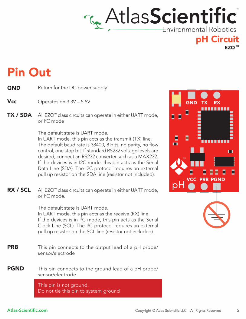
Pin OutGND
TX / SDA
RX / SCL
PRB
PGND
Vcc
Return for the DC power supply
Operates on 3.3V – 5.5V
All EZO™ class circuits can operate in either UART mode, or I2C mode
The default state is UART mode.In UART mode, this pin acts as the transmit (TX) line.The default baud rate is 38400, 8 bits, no parity, no flow control, one stop bit. If standard RS232 voltage levels are desired, connect an RS232 converter such as a MAX232. If the devices is in I2C mode, this pin acts as the Serial Data Line (SDA). The I2C protocol requires an external pull up resistor on the SDA line (resistor not included).
All EZO™ class circuits can operate in either UART mode, or I2C mode.
The default state is UART mode.In UART mode, this pin acts as the receive (RX) line.If the devices is in I2C mode, this pin acts as the Serial Clock Line (SCL). The I2C protocol requires an external pull up resistor on the SCL line (resistor not included).
This pin connects to the output lead of a pH probe/sensor/electrode
This pin is not ground. Do not tie this pin to system ground
This pin connects to the ground lead of a pH probe/sensor/electrode

pH Circuit
Atlas-Scientific.com Copyright © Atlas Scientific LLC All Rights Reserved
EZO TM
6
Device operationWhen an EZO™ class circuit is first powered up the boot sequence will begin. This is indicated by the LED moving from Red to Green to Blue. The boot up sequence takes 1 second. Once the device has booted up the circuit will output:
*RE<CR>Indicating the device is ready for operation.
The Green LED will also stay lit, indicating that the EZO™ class circuit is now operational in its default state.
Default stateModeUART
Baud rate38,400 bps 8 data bits1 stop bitno parityno flow control
Reading time1 reading every second
Probe type Any off the shelf single, or double junction pH probe/sensor/electrode
LEDs:EnabledSteady Green= Power on/ standbyRed double blink = Command received and not understoodGreen double blink per data packet = Continuous data streamingCyan = taking a reading
Data output: String Encoding: ASCII characters followed by a carriage return <CR> Maximum string length: 10 characters
If the response code is enabled the EZO™ class circuit will respond “*OK<CR>” after a command is acknowledged. If an unknown command is sent the pH Circuit will respond “*ER<CR>” this will happen whether or not response codes are enabled
pH CircuitEZO TM
Atlas-Scientific.com Copyright © Atlas Scientific LLC All Rights Reserved 7
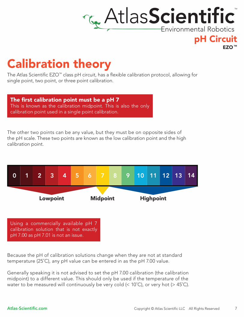
The Atlas Scientific EZO™ class pH circuit, has a flexible calibration protocol, allowing for single point, two point, or three point calibration.
The other two points can be any value, but they must be on opposite sides of the pH scale. These two points are known as the low calibration point and the high calibration point.
Because the pH of calibration solutions change when they are not at standard temperature (25˚C), any pH value can be entered in as the pH 7.00 value.
Generally speaking it is not advised to set the pH 7.00 calibration (the calibration midpoint) to a different value. This should only be used if the temperature of the water to be measured will continuously be very cold (< 10˚C), or very hot (> 45˚C).
Calibration theory
The first calibration point must be a pH 7This is known as the calibration midpoint. This is also the only calibration point used in a single point calibration.
Using a commercially available pH 7 calibration solution that is not exactly pH 7.00 as pH 7.01 is not an issue.
Lowpoint HighpointMidpoint
14

pH Circuit
Atlas-Scientific.com Copyright © Atlas Scientific LLC All Rights Reserved
EZO TM
8
Two point calibration will provide high accuracy between pH 7 and the second point calibrated against, such as a pH 4.
Three point calibration will provide high accuracy over the full pH range. 3 point calibration at pH 4, 7 and 10 should be considered the standard.
Only the calibration at pH 7 is mandatory. The other calibration points can be any value. The further apart these values are, the greater the accuracy.
No calibration
One point calibration
MidpointLowpoint
MidpointLowpoint Highpoint
14
Midpoint

pH CircuitEZO TM
Atlas-Scientific.com Copyright © Atlas Scientific LLC All Rights Reserved 9
Design considerations
Power and data isolation
The Atlas Scientific EZO™ pH circuit is a micro-computer system that is specifically designed to be embedded into a larger system. The EZO™ pH circuit is not a completed product. The embedded systems engineer is responsible for building a completed working product.
The Atlas Scientific EZO™ pH circuit is a very sensitive device. This sensitivity is what gives the pH circuit its accuracy. This also means that the pH circuit is capable of reading micro-voltages that are bleeding into the water from unnatural sources such as pumps, solenoid valves or other sensors.
Pump
When electrical noise is interfering with the pH readings it is common to see rapidly fluctuating readings or readings that are consistently off. To verify that electrical noise is causing inaccurate readings place the pH probe in a cup of water by itself. The readings should stabilize quickly, confirming that electrical noise was the issue.

pH Circuit
Atlas-Scientific.com Copyright © Atlas Scientific LLC All Rights Reserved
EZO TM
10
To correct this problem the power and data lines need to be electrically isolated. There is no one single method of doing this. This is just one of many ways to do so.
The SI8600 is a digital isolator with two bidirectional channels, which makes it excellent for use with I2C and UART protocols. This Part requires isolated power and pull ups on both channels on the isolated and non-isolated inputs. Pull up resistors can be anything from 3k to 10k.
The ROE-0505s is an isolated DC/DC converter that can handle 5V @ 1W. This part uses a Transformer that provides a 1:1 ratio (5V in and 5v out) however we have seen that 5V in produces 5.4V out and we recommend using a 5V regulator on its output.
Note: The Isolated Ground is different from the non-isolated Ground, these two lines should not be connected together.

pH CircuitEZO TM
Atlas-Scientific.com Copyright © Atlas Scientific LLC All Rights Reserved 11
Board mounting The Atlas Scientific EZO™ pH circuit should be tested in a bread board with different colored jumper wires connecting to each pin of the EZO™ pH circuit.
The EZO™ pH circuit should not have wires for other devices in your system laying on top of it. If long term use is desired a PCB should be made to hold the device.
Protoboards or Perfboards should never be used.
Using Protoboards or Perfboards will void your devices warranty.No support will be given.
Micro-shorts and bleeding voltages are very common when using such boards.Achieving stable reading can be quite difficult or impossible.

pH Circuit
Atlas-Scientific.com Copyright © Atlas Scientific LLC All Rights Reserved
EZO TM
12
EZO TM
pH Circuit
UART ModeTM

pH CircuitEZO TM
Atlas-Scientific.com Copyright © Atlas Scientific LLC All Rights Reserved 13
UART mode command quick reference
All commands are ASCII strings or single ASCII characters
There are a total of 13 different commands that can be given to the EZO™ class pH circuit.
Command Function Default state
C,<1|0|?>
Cal,<type,nnn>
I
I2C,<nnn>
L,<1|0|?>
Name,<nnn|?>
R
Response,<1|0|?>
Serial,<nnn>
Sleep
Status
T,<XX.XX|?>
X
Enabled
User must calibrate
N/A
Not set
LEDs Enabled
Not set
N/A
Enabled
38400
N/A
N/A
25˚C
N/A
Enable / Disable or Query continuous readings (pg.15)
Performs calibration (pg.18)
Device information (pg.20)
Sets the I2C ID number (pg.26)
Enable / Disable or Query the LEDs (pg.14)
Set or Query the name of the device (pg.20)
Returns a single reading (pg.16)
Enable / Disable or Query response code (pg.21)
Set the baud rate (pg.24)
Enter low power sleep mode (pg.23)
Retrieve status information (pg.22)
Set or Query the temperature compensation (pg.17)
Factory reset (pg.25)

pH Circuit
Atlas-Scientific.com Copyright © Atlas Scientific LLC All Rights Reserved
EZO TM
14
UART mode LED color definitions:Steady Green= Power on/ standby Red double blink = Command received and not understood Green blink=Data transmission sent Cyan= taking a reading
Command syntaxL,1<CR> LED enable L,0<CR> LED disableL,? <CR> Query the LED
Device responseL,1 <CR>(If the response code is enabled, the EZO™ class circuit will respond “*OK<CR>”)The Led will be enabled and the green power on/ standby LED will turn on L,0 <CR>(If the response code is enabled, the EZO™ class circuit will respond “*OK<CR>”)The Led will be disabled
L,? <CR>(If the response code is enabled, the EZO™ class circuit will respond “*OK<CR>”) ?L,1<CR> if the LED is enabled?L,0<CR> if the LED is disabled
UART command definitions
LED control
<CR> represents a carriage return (ASCII 13). The user does not transmit the literal string “<CR>”. Commands are not case sensitive.
All EZO™ class circuits have a tri color LED, used to indicate device operation.

pH CircuitEZO TM
Atlas-Scientific.com Copyright © Atlas Scientific LLC All Rights Reserved 15
Continuous reading mode
<CR> represents a carriage return (ASCII 13). The user does not transmit the literal string “<CR>”. Commands are not case sensitive.
All EZO™ class circuits are capable of continuous mode operation. In continuous mode, the device will output its readings, one after the other continuously until the continuous mode disable command has been issued. All EZO™ class circuits are defaulted to operate in continuous mode. If the LEDs are enabled, each time a data transmission occurs, the green LED will blink.
Command syntaxC,1<CR> Continuous mode enable C,0<CR> Continuous mode disable C,?<CR> Query continuous mode
Device responseC,1 <CR>(If the response code is enabled, the EZO™ class circuit will respond “*OK<CR>”)The EZO™ class pH circuit, will output a numeric string containing the pH once per second
pH<CR> (1 second)pH<CR> (2 seconds)pH<CR> (n* seconds)
C,0 <CR>(If the response code is enabled, the EZO™ class circuit will respond “*OK<CR>”)Continuous data transmission will cease.
C,? <CR>(If the response code is enabled, the EZO™ class circuit will respond “*OK<CR>”) ?C,1<CR> if continuous mode is enabled.?C,0<CR> if continuous mode is disabled.

pH Circuit
Atlas-Scientific.com Copyright © Atlas Scientific LLC All Rights Reserved
EZO TM
16
Single reading mode
<CR> represents a carriage return (ASCII 13). The user does not transmit the literal string “<CR>”. Commands are not case sensitive.
All EZO™ class circuits are capable of taking a single reading upon request. If the LEDs are enabled, each time a data transmission occurs, the green LED will blink.
Command syntaxR<CR> Returns a single reading
Device response(If the response code is enabled, the EZO™ class circuit will respond “*OK<CR>”)The EZO™ class pH circuit, will output a single string containing a pH reading 1 second after the command was issued.
pH<CR> (1 second)

pH CircuitEZO TM
Atlas-Scientific.com Copyright © Atlas Scientific LLC All Rights Reserved 17
Temperature compensation
<CR> represents a carriage return (ASCII 13). The user does not transmit the literal string “<CR>”. Commands are not case sensitive.
In order to achieve the most accurate possible readings, the temperature of the liquid being measured must be transmitted to the EZO™ class pH circuit. The embedded systems engineer must keep in mind that the EZO™ class pH circuit, cannot read the temperature from a pH probe or from a temperature probe. Another device must be used to read the temperature. EZO™ class pH circuit, has its default temperature set at 25˚C. The temperature at which to compensate against can be changed at any time using the “T” command.
Temperature is always in Celsius
Command syntax(Using an example temperature 19.5)
T,19.5<CR> Where the temperature is any value; floating point or int, in ASCII formT,?<CR> Query the set temperature
Device responseT,19.5<CR>(If the response code is enabled, the EZO™ class circuit will respond “*OK<CR>”)There is no other output associated output with this command
T,?<CR>(If the response code is enabled, the EZO™ class circuit will respond “*OK<CR>”)?T,19.5 <CR>

pH Circuit
Atlas-Scientific.com Copyright © Atlas Scientific LLC All Rights Reserved
EZO TM
18
Calibration
<CR> represents a carriage return (ASCII 13). The user does not transmit the literal string “<CR>”. Commands are not case sensitive.
The Atlas Scientific EZO™ class pH circuit, has a flexible calibration protocol, allowing for single point, two point, or three point calibration.
During calibration, it is required that pH 7 calibration be done first. Calibration can be done at a maximum of 3 points. These three points are known as the low calibration point, the middle calibration point and the high calibration point. Where pH 7.XX must be the first calibration point. This is known as the middle calibration point.
Command syntaxCal,mid,X.XX<CR> Where X.XX is any floating point value that represents the pH midpoint. In most cases this should be 7.00
14
Lowpoint
Highpoint
Midpoint
14
14
Cal,low,X.XX<CR> Where X.XX is any floating point value that represents a low calibration point (pH 1 to pH 6)
Cal,high,XX.XX<CR> Where XX.XX is any floating point value that represents a high calibration point (pH 8 to pH 14)

pH CircuitEZO TM
Atlas-Scientific.com Copyright © Atlas Scientific LLC All Rights Reserved 19
Device response
Cal,clear<CR>(If the response code is enabled, the EZO™ class circuit will respond “*OK<CR>”)There is no other output associated output with this command.
Cal,mid,X.XX<CR>(If the response code is enabled, the EZO™ class circuit will respond “*OK<CR>”)The LED will turn Cyan during the calibration.
Cal,low,X.XX<CR>(If the response code is enabled, the EZO™ class circuit will respond “*OK<CR>”)The LED will turn Cyan during the calibration.
Cal,high,XX.XX<CR>(If the response code is enabled, the EZO™ class circuit will respond “*OK<CR>”)The LED will turn Cyan during the calibration.
Cal,?<CR> (If the response code is enabled, the EZO™ class circuit will respond “*OK<CR>”)
If not calibrated: ?CAL,0If single point calibration: ?CAL,1If two point calibration: ?CAL,2If three point calibration: ?CAL,3
Issuing the cal,mid command after the EZO™ class pH circuit has been calibrated will clear other calibration points. Full calibration will have to be redone.
Issuing a cal,low or cal,high command can be done at any time and will have no effect on other previously set calibration points.

pH Circuit
Atlas-Scientific.com Copyright © Atlas Scientific LLC All Rights Reserved
EZO TM
20
Device Identification
Device information
<CR> represents a carriage return (ASCII 13). The user does not transmit the literal string “<CR>”. Commands are not case sensitive.
All EZO™ class circuits are capable of being assigned a name. This is a simple way to identify the device in a system that consists of multiple EZO™ class circuits. A name can consist of any combination of ASCII characters, with a length of 1 to 16 characters long, no blank spaces.
The EZO™ class circuit can identify itself by device type and firmware version.This is done by transmitting the “I” command.
Command syntaxI<CR> Device information
Device response?I,pH,1.0<CR>(If the response code is enabled, the EZO™ class circuit will respond “*OK<CR>”)
Command syntaxNAME,nnn<CR> Sets the device name, where nnn is the given name.NAME,?<CR> Query the device name Device responseNAME,DEVICE_1<CR>(If the response code is enabled, the EZO™ class circuit will respond “*OK<CR>”)There is no other output associated output with this command.
NAME,?<CR>(If the response code is enabled, the EZO™ class circuit will respond “*OK<CR>”)?NAME, DEVICE_1<CR>

pH CircuitEZO TM
Atlas-Scientific.com Copyright © Atlas Scientific LLC All Rights Reserved 21
Response codes
A list of response codes
<CR> represents a carriage return (ASCII 13). The user does not transmit the literal string “<CR>”. Commands are not case sensitive.
The Atlas Scientific EZO™ class circuits, have 7 response codes to help the user understand how the device is operating, and to aid in the construction of a state machine to control the EZO™ class circuit. All EZO™ class devices indicate a response code has been triggered, by transmitting a string with the prefix “*” and ending with a carriage return <CR>.
*ER An unknown command has been sent *OV The circuit is being ovearvolted (VCC>=5.5V)*UV The circuit is being undervolted (VCC<=3.1V)*RS The circuit has reset *RE The circuit has completed boot up*SL The circuit has been put to sleep*WA The circuit has woken up from sleep
Only the response code “*OK” can be disabled.Disabling this response code is done using the “response” command.
Command syntaxRESPONSE,1<CR> Enable response code (default)RESPONSE,0<CR> Disable response code RESPONSE,?<CR> Query the response code Device responseRESPONSE,1<CR>EZO™ class circuit will respond “*OK<CR>”
RESPONSE,0<CR>There is no response to this command
RESPONSE,?<CR> ?RESPONSE,1<CR> If the response code is enabled ?RESPONSE,0<CR> If the response code is disabled

pH Circuit
Atlas-Scientific.com Copyright © Atlas Scientific LLC All Rights Reserved
EZO TM
22
Reading the status of the device
Restart codes
<CR> represents a carriage return (ASCII 13). The user does not transmit the literal string “<CR>”. Commands are not case sensitive.
The Atlas Scientific™ EZO™ class circuit, is able to report its voltage at the VCC pin and reason the device was last restarted.
P power on resetS software resetB brown out resetW watchdog resetU unknown
Command syntaxSTATUS<CR>
Device response(If the response code is enabled, the EZO™ class circuit will respond “*OK<CR>”)
?STATUS,P,5.038<CR>
Where: P is the reason for the last reset eventWhere: 5.038 is the its voltage at the VCC

pH CircuitEZO TM
Atlas-Scientific.com Copyright © Atlas Scientific LLC All Rights Reserved 23
Low power state
<CR> represents a carriage return (ASCII 13). The user does not transmit the literal string “<CR>”. Commands are not case sensitive.
To conserve energy in between readings, the Atlas Scientific™ EZO™ class circuit, can be put into a low power sleep state. This will turn off the LEDs and shut down almost all of the internal workings of the EZO™ class circuit. The power consumption will be reduced to 1.16 mA at 5V and 0.995 mA at 3.3V. To wake the EZO™ class circuit, send it any character.
Command syntaxSLEEP<CR> Enter low power sleep state
Device response(If the response code is enabled, the EZO™ class circuit will respond “*OK<CR>”)*SL<CR>
Device response to wake up:*WA<CR>

pH Circuit
Atlas-Scientific.com Copyright © Atlas Scientific LLC All Rights Reserved
EZO TM
24
Change baud rate
<CR> represents a carriage return (ASCII 13). The user does not transmit the literal string “<CR>”. Commands are not case sensitive.
The Atlas Scientific EZO™ class circuit, has 8 possible baud rates it can operate at.The default baud rate is
38400 bps 8 data bits1 stop bitno parityno flow control
Data bits, stop bits, parity and flow control are fixed and cannot be changed.
1. 300 bps2. 1200 bps3. 2400 bps4. 9600 bps5. 19200 bps6. 38400 bps7. 57600 bps8. 115200 bps
Command syntax(Using an example baud rate of 9600)SERIAL,9600<CR>
Device response(If the response code is enabled, the EZO™ class circuit will respond “*OK<CR>”) The EZO™ class circuit will respond with a Purple LED double blink. The EZO™ class circuit will then restart at the new baud rate.
The LED blink will happen even if the LEDs are disabled.

pH CircuitEZO TM
Atlas-Scientific.com Copyright © Atlas Scientific LLC All Rights Reserved 25
Factory reset
<CR> represents a carriage return (ASCII 13). The user does not transmit the literal string “<CR>”. Commands are not case sensitive.
All EZO™ class circuits, are capable of resetting themselves to the original factory settings. Issuing a factory reset will:
Reset the calibration back to factory defaultReset default temperature to 25°CSet debugging LED to on.Enable response codes
This command will not change the set baud rate.
Command syntaxX<CR> Factory reset
Device response(If the response code is enabled, the EZO™ class circuit will respond “*OK<CR>”)The EZO™ class circuit, will respond: *RE<CR>

pH Circuit
Atlas-Scientific.com Copyright © Atlas Scientific LLC All Rights Reserved
EZO TM
26
Switch from UART mode to I2C mode
<CR> represents a carriage return (ASCII 13). The user does not transmit the literal string “<CR>”. Commands are not case sensitive.
Transmitting the command I2C,[n] will set the EZO™ class circuit into I2C mode from UART mode. Where [n] represents any number from 1-127. The I2C address is sent in decimal ASCII form. Do not send the address in hexadecimal ASCII form. Command syntax(Using as example an I2C ID number of 99)I2C[99]<CR>
Device responseIf an address > 127 is given
*ER Indicating an error has occurred
If an address >0 and <128 is given(If the response code is enabled, the EZO™ class circuit will respond “*OK<CR>”)
*RS<CR> The device will restart in I2C mode
The Green LED used to indicate that the device is powered and awaiting an instruction will now change to Blue.

pH CircuitEZO TM
Atlas-Scientific.com Copyright © Atlas Scientific LLC All Rights Reserved 27
Manual switching to I2C mode
<CR> represents a carriage return (ASCII 13). The user does not transmit the literal string “<CR>”. Commands are not case sensitive.
All EZO™ class circuits can be manually switched from UART mode, to I2C mode. If this is done the EZO™ class pH circuit, will set its I2C address to 99 (0x63).
1. Cut the power to the device2. Short the right probe pin to the TX pin3. Power the device4. Wait for LED to change from Green to Blue5. Remove the short from the probe pin to the TX pin.6. Power cycle the device7. The device is now I2C mode.
short

pH Circuit
Atlas-Scientific.com Copyright © Atlas Scientific LLC All Rights Reserved
EZO TM
28
EZO TM
pH Circuit
I2C ModeTM

pH CircuitEZO TM
Atlas-Scientific.com Copyright © Atlas Scientific LLC All Rights Reserved 29
I2C modeAn I2C address can be any number from 1-127. If the EZO™ Class pH circuit was put into I2C mode by jumping PRB to TX, the I2C address is 99(0x63).
Once an EZO™ class device has been put into I2C mode the green power LED that was used in UART mode will now switch to a Blue LED. This indicates the device is now in I2C mode.
The I2C protocol is considerably more complex than the UART (RS-232) protocol.Atlas Scientific assumes the embedded systems engineer understands this protocol.
Communication to the EZO™ class device is controlled by the master. The EZO™ class device as an I2C slave. The slave device is not able to initiate any data transmissions.
An I2C write event is defined as such
An I2C read event is defined as such
In order to get the response from device, it is necessary to initiate a read command. The I2C protocol does not permit the slave device to initiate any data transmissions.

pH Circuit
Atlas-Scientific.com Copyright © Atlas Scientific LLC All Rights Reserved
EZO TM
30
Data from a read back eventThe first byte of the data read back, is the response code. This byte informs the master of the status of the data about to be read back. For all commands, the first byte of the read data is the response code, which is defined as
Value Meaning
255
254
1
2
No Data – there is no pending request, so there is no data to return from the circuit
Pending – the request is still being processed. Ensure that you have waited the minimum time to guarantee a response
Success – the requested information is ready for transmission. There may be more bytes following this which are returned data
Failed – the request failed
The bytes transmitted after that, will be the requested data. When all the data has been transmitted each additional byte will be a NULL.
ExampleA read request when no command has been given.

pH CircuitEZO TM
Atlas-Scientific.com Copyright © Atlas Scientific LLC All Rights Reserved 31
All I2C mode responses are in ASCII format however, they do not terminate with a <CR> rather, they terminate with a NULL. The Null termination makes data manipulation easier once it has been received.
ExampleEZO™ class device responds to a request for a reading
12.3 ≠ float 12.3 =byte[5] Byte[0]= 1 (decimal 1) byte[1]= “1” (ASCII 49) byte[2]= “2” (ASCII 50) byte[3]= “.” (ASCII 46) byte[4]= “3” (ASCII 51) byte[5]= NULL (ASCII 0)
I2C timingWhen a command is issued to the EZO™ class device, a certain amount of time must be allowed to pass before the data is ready to be read. Each command specifies the delay needed before the data can be read back. EZO™ class devices do not support I2C clock stretching. All commands are sent to the EZO™ class device in the same ASCII format as in UART mode however, there is no <CR> sent at the end of the transmission.

pH Circuit
Atlas-Scientific.com Copyright © Atlas Scientific LLC All Rights Reserved
EZO TM
32
I2C command quick referenceThere are a total of 9 different commands that can be given to the EZO™ class pH circuit.
Command Function
Cal,<type,nnn>
I
L,<1|0|?>
R
Serial,<nnn>
Sleep
Status
T,<XX.XX|?>
X
Performs calibration (pg.36)
Device information (pg.39)
Enable / Disable or Query the LEDs (pg.33)
Returns a single reading (pg.34)
Switch back to UART mode (pg.42)
Enter low power sleep mode (pg.41)
Retrieve status information (pg.40)
Set or Query the temperature compensation (pg.35)
Factory reset (pg.43)
pH CircuitEZO TM
Atlas-Scientific.com Copyright © Atlas Scientific LLC All Rights Reserved 33
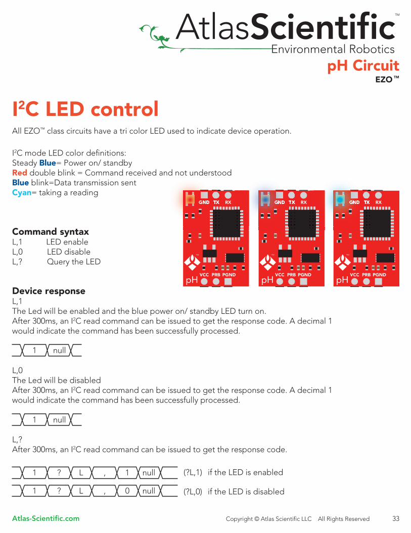
I2C LED controlAll EZO™ class circuits have a tri color LED used to indicate device operation.
I2C mode LED color definitions:Steady Blue= Power on/ standby Red double blink = Command received and not understoodBlue blink=Data transmission sent Cyan= taking a reading
Command syntaxL,1 LED enable L,0 LED disableL,? Query the LED
Device responseL,1The Led will be enabled and the blue power on/ standby LED turn on. After 300ms, an I2C read command can be issued to get the response code. A decimal 1 would indicate the command has been successfully processed.
L,0The Led will be disabledAfter 300ms, an I2C read command can be issued to get the response code. A decimal 1 would indicate the command has been successfully processed.
L,?After 300ms, an I2C read command can be issued to get the response code.
(?L,1) if the LED is enabled
(?L,0) if the LED is disabled

pH Circuit
Atlas-Scientific.com Copyright © Atlas Scientific LLC All Rights Reserved
EZO TM
34
I2C take readingWhen a reading is taken, the LED (if enabled) will turn Cyan, indicating that a reading is being taken. Once the reading has been taken, the LED will turn back to Blue.
Command syntaxR Returns a single reading
Time until instruction is processed: 1 second
Device responseAfter 1 second, an I2C read command can be issued to get the response:
pH represents many bytes. The string will be no longer than 7 bytes.
1 Second time has passed

pH CircuitEZO TM
Atlas-Scientific.com Copyright © Atlas Scientific LLC All Rights Reserved 35
I2C Temperature compensation In order to achieve the most accurate possible readings, the temperature of the liquid being measured must be transmitted to the EZO™ class pH circuit. The embedded systems engineer must keep in mind that the EZO™ class pH circuit, cannot read the temperature from a pH probe, or from a temperature probe. Another device must be used to read the temperature. EZO™ class pH circuit, has its default temperature set at 25˚C. The temperature, at which to compensate against, can be changed at any time using the “T” command.
Command syntax(Using an example temperature 19.5)
T,19.5 Where the temperature is any value; floating point, or int, in ASCII form
T,? Query the set temperature
Time until instruction is processed: 300ms
Device responseT,19.5After 300ms, an I2C read command can be issued to get the response code. A decimal 1 would indicate the command has been successfully processed.
T,?After 300ms, an I2C read command can be issued to get the response
(?T,19.5)

pH Circuit
Atlas-Scientific.com Copyright © Atlas Scientific LLC All Rights Reserved
EZO TM
36
The Atlas Scientific EZO™ class pH circuit, has a flexible calibration protocol, allowing for single point, two point or three point calibration.
The only requirement for calibration is that pH 7 calibration must be done first. Calibration can be done at a maximum of 3 points. These three points are known as the low calibration point, the middle calibration point and the high calibration point. Where pH 7.XX must be the first calibration point. This is known as the middle calibration point.
Command syntaxCal,clear Clears all calibration data
Cal,mid,X.XX Where X.XX is any integer, or floating point value that represents the pH midpoint. In most cases this should be 7.00
Cal,low,X.XX Where X.XX is any integer, or floating point value that represents a low calibration point (pH 1 to pH 6)
Cal,high,XX.XX Where XX.XX is any integer, or floating point value that represents a high calibration point (pH 8 to pH 14)
Cal,? Query the calibration
I2C Calibration
14
Midpoint
Highpoint
14
Lowpoint
14

pH CircuitEZO TM
Atlas-Scientific.com Copyright © Atlas Scientific LLC All Rights Reserved 37
Device responseCal,clearThe LED will turn Cyan during the calibration.After 300ms, an I2C read command can be issued to get the response code.A decimal 1 would indicate the command has been successfully processed.
Cal,mid,X.XXThe LED will turn Cyan during the calibration.After 1.3 seconds, an I2C read command can be issued to get the response code.A decimal 1 would indicate the command has been successfully processed.
Cal,low, X.XX The LED will turn Cyan during the calibration.After 1.3 seconds, an I2C read command can be issued to get the response code.A decimal 1 would indicate the command has been successfully processed.
Cal,high, XX.XX The LED will turn Cyan during the calibration.After 1.3 seconds, an I2C read command can be issued to get the response code.A decimal 1 would indicate the command has been successfully processed.

pH Circuit
Atlas-Scientific.com Copyright © Atlas Scientific LLC All Rights Reserved
EZO TM
38
Cal,? After 300ms, an I2C read command can be issued to get the response code.
If not calibrated
(?CAL,0)
If single point calibration
(?CAL,1)
If two point calibration
(?CAL,2)
If three point calibration
(?CAL,3)
Issuing the cal,mid command after the EZO™ class pH circuit has been calibrated will clear other calibration points. Full calibration will have to be redone.
Issuing a cal,low or cal,high command can be done at any time and will have no effect on other previously set calibration points.
pH CircuitEZO TM
Atlas-Scientific.com Copyright © Atlas Scientific LLC All Rights Reserved 39
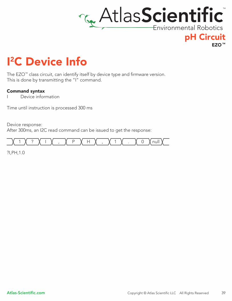
I2C Device Info The EZO™ class circuit, can identify itself by device type and firmware version.This is done by transmitting the “I” command.
Command syntaxI Device information
Time until instruction is processed 300 ms
Device response:After 300ms, an I2C read command can be issued to get the response:
?I,PH,1.0

pH Circuit
Atlas-Scientific.com Copyright © Atlas Scientific LLC All Rights Reserved
EZO TM
40
Reading the status of the device in I2C modeThe Atlas Scientific™ EZO™ class circuit, is able to report its voltage at the VCC pin and the reason the device was last restarted.
Restart codesP power on resetS software resetB brown out resetW watchdog resetU unknown
Command syntaxSTATUSTime until instruction is processed, 300ms
Device responseAfter 300ms, an I2C read command can be issued, to get the response
?STATUS,P,5.038
Where: P is the reason for the last reset eventWhere: 5.038 is the its voltage at the VCC

pH CircuitEZO TM
Atlas-Scientific.com Copyright © Atlas Scientific LLC All Rights Reserved 41
I2C Low power stateTo conserve energy in between readings, the Atlas Scientific pH EZO™ class circuit can be put into a low power sleep state. This will turn off the LEDs and shut down almost all of the internal workings of the EZO™ class circuit. The power consumption will be reduced to 1.16 mA at 5V and 0.995 mA at 3.3V. To wake the EZO™ class circuit, send it any command.
Command syntaxSLEEP Enter low power sleep state Time until instruction is processed, 300ms Device responseIf the LEDs are enabled, the Blue LED will blink and then turn off.There is no other output associated with this command.

pH Circuit
Atlas-Scientific.com Copyright © Atlas Scientific LLC All Rights Reserved
EZO TM
42
Switch from I2C mode to UART modeTransmitting the command serial,<n> will set the EZO™ class circuit into UART mode from I2C mode. Where [n] represents any of one the 8 available baud rates. Command syntax(Using as example a baud rate of 9600)
SERIAL,9600
Device responseIf an incorrect baud rate is sent the device will not switchinto UART mode and the Red LED will flash.
If a correct baud rate is given:The Blue LED used to indicate that the device is powered and awaiting an instruction will now change to Green.

pH CircuitEZO TM
Atlas-Scientific.com Copyright © Atlas Scientific LLC All Rights Reserved 43
Factory resetAll EZO™ class circuits, are capable of resetting themselves to the original factory settings. Issuing a factory reset will:
Reset the calibration back to factory defaultReset default temperature to 25°CSet debugging LED to on.Enable response codes
This command will not change the set I2C address
Command syntaxX factory reset
Device responseAfter 300ms the STATUS command can be issued to see that the device was reset.
?STATUS,S,5.038
Where: S is the reason for the last reset event (software reset)Where: 5.038 is the its voltage at the VCC

pH Circuit
Atlas-Scientific.com Copyright © Atlas Scientific LLC All Rights Reserved
EZO TM
44
Manual switching to UART modeAll EZO™ class circuits, can be manually switched from I2C mode to UART mode. If this is done, the EZO™ class pH circuit, will set its baud rate to 38400.
1. Cut the power to the device2. Short the right probe pin to the TX pin3. Power the device4. Wait for LED to change from Blue to Green5. Remove the short from the probe pin to the TX pin6. Power cycle the device7. The device is now UART mode
short

pH CircuitEZO TM
Atlas-Scientific.com Copyright © Atlas Scientific LLC All Rights Reserved 45
Circuit dimensions
TM

pH Circuit
Atlas-Scientific.com Copyright © Atlas Scientific LLC All Rights Reserved
EZO TM
46
How to make a footprint for the Atlas ScientificTM EZOTM pH circuit
1. In your CAD software place an 8 position header.
2. Place a 3 position header at both top and bottom of the 8 position header as shown.
3. Once this is done, you can delete the 8 position header. Make sure that the two 3 position headers are 17.78mm (0.7”) apart from each other.

pH CircuitEZO TM
Atlas-Scientific.com Copyright © Atlas Scientific LLC All Rights Reserved 47
Wiring diagram• To connect the Circuit to your microcontroller, follow the diagram below.• The BNC shield can be connected to any ground line.• Make sure your Circuit and microcontroller share a common ground.• TX on your Circuit connects to RX on your microcontroller. • If in I2C mode connect SDA to SDA and SCL to SCL• *4.7k pull up resistor on SDA and SCL may be required
Correct Incorrect
Do not connect with jumper wires
The Atlas Scientifi c™ EZO™ class pH circuit is a piece of sensitive equipment. Debugging should be done in a bread board; Not like what is show in this photo.

pH Circuit
Atlas-Scientific.com Copyright © Atlas Scientific LLC All Rights Reserved
EZO TM
48
Warranty
The debugging phase
Atlas Scientific™ Warranties the EZO™ class pH circuit to be free of defect during the debugging phase of device implementation, or 30 days after receiving the EZO™class pH circuit (which ever comes first).
The debugging phase as defined by Atlas Scientific™, is the time period when the EZO™
class pH circuit is inserted into a bread board, or shield, and is connected to a microcontroller according to the wiring diagram on pg. 47. Reference this wiring diagram for a connection to USB debugging device, or if a shield is being used, when it is connected to its carrier board.
If the EZO™ class pH circuit is being debugged in a bread board, the bread board must be devoid of other components. If the EZO™ class pH circuit is being connected to a microcontroller, the microcontroller must be running code that has been designed to drive the EZO™ class pH circuit exclusively and output the EZO™ class pH circuit data as a serial string.
It is important for the embedded systems engineer to keep in mind that the following activities will void the EZO™ class pH circuit warranty:
• Soldering any part of the EZO™ class pH circuit • Running any code, that does not exclusively drive the EZO™ class pH circuit and output its data in a serial string• Embedding the EZO™ class pH circuit into a custom made device • Removing any potting compound

pH CircuitEZO TM
Atlas-Scientific.com Copyright © Atlas Scientific LLC All Rights Reserved 49
Reasoning behind this warranty Because Atlas Scientific™ does not sell consumer electronics; once the device has been embedded into a custom made system, Atlas Scientific™ cannot possibly warranty the EZO™ class pH circuit, against the thousands of possible variables that may cause the EZO™ class pH circuit to no longer function properly. Please keep this in mind:
1. All Atlas Scientific™ devices have been designed to be embedded into a custom made system by you, the embedded systems engineer. 2. All Atlas Scientific™ devices have been designed to run indefinitely without failure in the field. 3. All Atlas Scientific™ devices can be soldered into place, however you do so at your own risk.
Atlas Scientific™ is simply stating that once the device is being used in your application, Atlas Scientific™ can no longer take responsibility for the EZO™ class pH circuits continued operation. This is because that would be equivalent to Atlas Scientific™ taking responsibility over the correct operation of your entire device.
TM

pH Circuit
Atlas-Scientific.com Copyright © Atlas Scientific LLC All Rights Reserved
EZO TM
50
TM