extrusion-resistant seals foran expandable tubular assembly
TRANSCRIPT

PATENTS
14Sealing Technology April 2013
and silicon carbide fibres; carbon nano-tubes; montmorillonite; bentonite; talc; isinglass; mica; molybdenum disulfide; glass beads; graphite; fullerene; anthracite powder; alu-minium, titanium and magnesium oxide; potassium titanate; boron nitride; and polyte-trafluoroethylene powder.Patent number: WO/2012/169604Inventor: M. SaitoPublication date: 13 December 2012
Shaft seal assembly
Applicant: Federal-Mogul Corp, USADetails are provided of a shaft-seal assembly for establishing a liquid-tight seal between a steering knuckle and an axle shaft. The seal assembly includes an outer case and a first elastomeric member, attached to one another. The elastomeric member has a castellated feature, including a plurality of projections extending radially outwards and separated from one another by a plurality of grooves. When the shaft seal assembly is installed in the steering knuckle, a cavity is presented between the knuckle and the first elastomeric member. Together, the grooves and cavity allow air to flow from a hub on one side of the seal assembly to a vacuum port in the steering knuckle. The cavity extends circum-ferentially around the seal assembly, which means that the air flow from the hub to the vacuum port does not depend on the orienta-tion of the assembly relative to the steering knuckle.Patent number: WO/2012/170777Inventors: R.M. Larson, D.C. Rupp, R. Fernandez, J. Stark and G.A. GrecaPublication date: 13 December 2012
Method for manufacturing a roller bearing seal
Applicant: Amsted Rail Co Inc, USAThis patent describes an improved method for making a bearing seal component for a tapered roller bearing that is designed to be fitted to a railway freight car’s axle. According to the pat-ent, this approach is significantly better than currently known methods, which usually uses a stamping operation that involves several steps requiring dedicated equipment and generates a large amount of scrap. The method detailed makes use of a sheet of steel – usually the mate-rial from which the bearing seal is composed – that is the exact width of the finished seal. The sheet is cut and initially run through a ring-forming machine. The ring produced is then welded, and run through the necessary number of pre-forming operations to create the formed
bearing seal. This method is seen as an improve-ment in terms of material use and efficiency.Patent number: WO/2012/173652Inventors: B.J. Spurlock and D.A. MarcellusPublication date: 20 December 2012
Radial shaft seal and assembly
Applicant: Federal-Mogul Powertrain Inc, USAIn general terms this invention provides details of a radial shaft seal assembly that has design features which enable a proper oil-side installation to be carried out, even under conditions of shaft-to-bore misalignment. Furthermore, it aims to provide support for the seal lip (of the seal assembly) against adverse seal-breaking movement through exposure to positive or negative pressure on the oil-side of the seal assembly.Patent number: WO/2012/174059Inventors: R.M. Toth and B.R. SedlarPublication date: 20 December 2012
Windscreen seal assembly
Applicant: Peugeot Citroen Automobiles Sa, FranceA windscreen seal assembly forms the subject of this patent. The assembly consists of a seal fixed to the lower edge of the windscreen of a motor vehicle and a scuttle (1) fixed to this seal (2). The scuttle comprises a lip (4), covering part (5) of the seal (2), extending along the lower edge (3a) of the windscreen (3), and part of the exterior face (3b) of the windscreen. A charac-teristic of this design is that the opposite end of the covering part (5) of the seal, to the lower edge (3a) of the windscreen (3), has a flexible thinned region (19) against which the end (4a) of the lip (4) of the scuttle (1) rests in order to bring this region into contact with the exterior face of the windscreen.Patent number: WO/2012/175834Inventor: F. GuidezPublication date: 27 December 2012
Surface-treating agent for an oil seal lip portion
Applicant: NOK Corp, JapanDisclosed is a surface-treating agent for an oil seal lip portion. It is compose of a lubricant fill-er and a compound that consists of an adduct of toluene diisocyanate and trimethylolpropane. This agent is applied to the surface of a vulcan-ised rubber lip portion. Applying it to surface of a sliding or moving part effectively lengthens service life and helps to reduce the energy con-sumed by the equipment that uses the oil seal.Patent number: WO/2012/176033 Inventor: K. KuniedaPublication date: 27 December 2012
Silane-terminated polycarbonate–polyester copolymers for sealants and adhesivesApplicant: Dow Global Technologies Llc, USA‘‘Cross-linkable’’ silyl group-containing poly-mers that may be made from polycarbon-ate–polyester copolymer polyols, and methods for making these materials, form the subject of this patent. The silane-terminated polymer is the reaction product of a polycarbonate–polyester copolymer polyol and an isocyanate capped ‘‘hydrosilylated’’ polymer. The latter is the reaction product of at least one isocyanate and a hydrosilylated polymer which, in turn, is the reaction product of a polymer that has at least one unsaturated group and at least one alcohol hydroxyl group in each molecule, and a compound having a hydrogen–silicon bond and a cross-linkable silyl group in each mol-ecule. The resulting polymer material exhibits improved viscosity properties, UV stability and is able to effectively weather harsh envi-ronmental conditions.Patent number: WO/2013/003051Inventors: K.R. Vyakaranam, H. Singh, L. Zhang, W.H. Heath and A. Singh and W.A. KooncePublication date: 3 January 2013
Extrusion-resistant seals for an expandable tubular assembly
Applicant: Weatherford/Lamb Inc, USAThis invention generally relates to extrusion-resistant seals for an expandable tubular assembly. In one aspect, an assembly is pro-vided for creating a seal between first and second tubular units. This seal assembly includes an annular member attached to the first tubular unit – the annular member hav-ing a groove formed on an outer surface. It
A windscreen seal assembly forms the subject of patent WO/2012/175834.
PATENTS
April 2013 Sealing Technology15
further includes a seal member disposed in the groove. The seal member has one or more anti-extrusion bands, and it is configured to be expandable – radially outwards – to make contact with an inner wall of the second tubular unit through the application of an outwardly directed force, which is supplied to an inner surface of the annular member.Patent number: WO/2013/002848Inventors: P.A. Reinhardt, R.A. Turley, B.J. Lirette and H.V. LePublication date: 3 January 2013
Blow-out preventer seal assembly
Applicant: National Oilwell Varco Lp, USAA shear sealing system for use in a blow-out preventer of a well-bore has been developed. The blow-out preventer includes a housing through which there is a bore and guideway. The shear sealing system includes at least one carriage, blades and seals. The carriage is posi-tioned so that it is able to slide in the guideway. The blades are carried by this carriage and are movable between a retracted and an extended position. A tubular unit of the well-bore is positioned in the bore. The blades engage with the tubular unit when in the extended posi-tion. A seal is formed about the tubular unit and with the blade, when the latter is in the extended position.Patent number: WO/2013/002971Inventors: P.L. Mcclanahan, J.A. Douty and R.M. WardPublication date: 3 January 2013
Brazed turbine seal
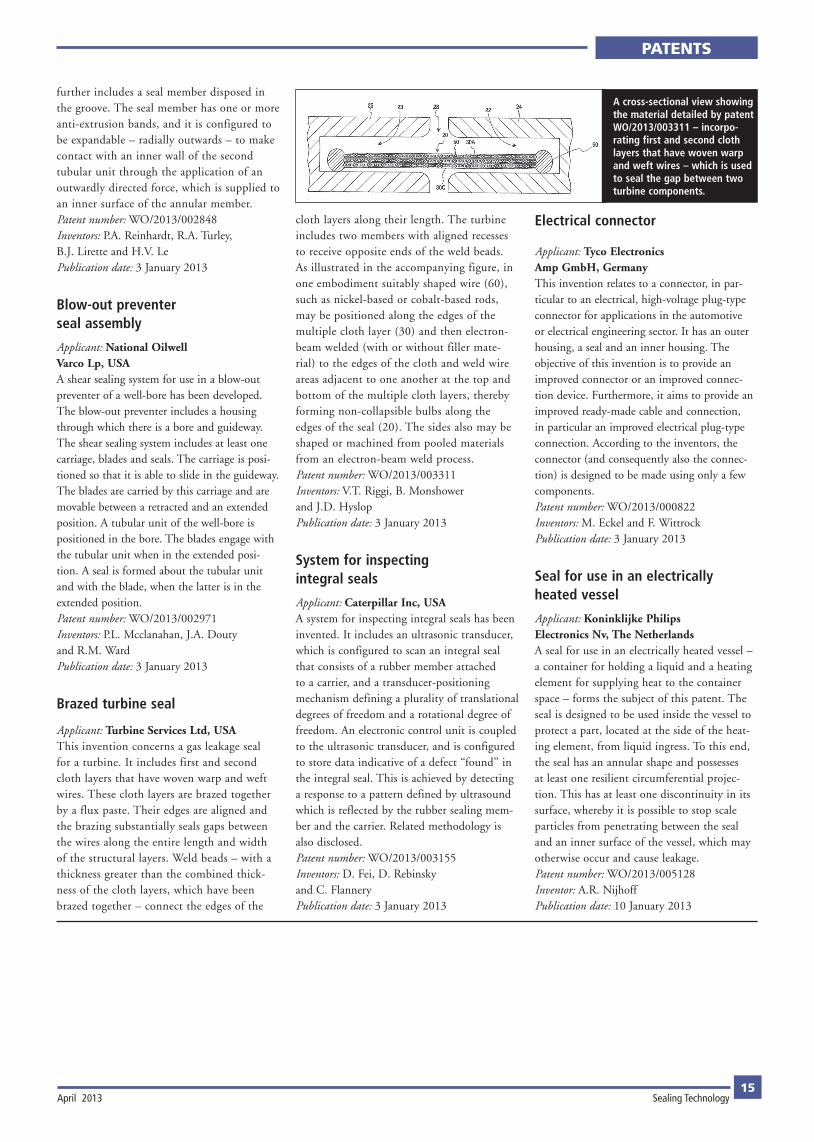
Applicant: Turbine Services Ltd, USAThis invention concerns a gas leakage seal for a turbine. It includes first and second cloth layers that have woven warp and weft wires. These cloth layers are brazed together by a flux paste. Their edges are aligned and the brazing substantially seals gaps between the wires along the entire length and width of the structural layers. Weld beads – with a thickness greater than the combined thick-ness of the cloth layers, which have been brazed together – connect the edges of the
cloth layers along their length. The turbine includes two members with aligned recesses to receive opposite ends of the weld beads. As illustrated in the accompanying figure, in one embodiment suitably shaped wire (60), such as nickel-based or cobalt-based rods, may be positioned along the edges of the multiple cloth layer (30) and then electron-beam welded (with or without filler mate-rial) to the edges of the cloth and weld wire areas adjacent to one another at the top and bottom of the multiple cloth layers, thereby forming non-collapsible bulbs along the edges of the seal (20). The sides also may be shaped or machined from pooled materials from an electron-beam weld process.Patent number: WO/2013/003311Inventors: V.T. Riggi, B. Monshower and J.D. HyslopPublication date: 3 January 2013
System for inspecting integral seals
Applicant: Caterpillar Inc, USAA system for inspecting integral seals has been invented. It includes an ultrasonic transducer, which is configured to scan an integral seal that consists of a rubber member attached to a carrier, and a transducer-positioning mechanism defining a plurality of translational degrees of freedom and a rotational degree of freedom. An electronic control unit is coupled to the ultrasonic transducer, and is configured to store data indicative of a defect ‘‘found’’ in the integral seal. This is achieved by detecting a response to a pattern defined by ultrasound which is reflected by the rubber sealing mem-ber and the carrier. Related methodology is also disclosed.Patent number: WO/2013/003155Inventors: D. Fei, D. Rebinsky and C. FlanneryPublication date: 3 January 2013
Electrical connector
Applicant: Tyco Electronics Amp GmbH, GermanyThis invention relates to a connector, in par-ticular to an electrical, high-voltage plug-type connector for applications in the automotive or electrical engineering sector. It has an outer housing, a seal and an inner housing. The objective of this invention is to provide an improved connector or an improved connec-tion device. Furthermore, it aims to provide an improved ready-made cable and connection, in particular an improved electrical plug-type connection. According to the inventors, the connector (and consequently also the connec-tion) is designed to be made using only a few components.Patent number: WO/2013/000822 Inventors: M. Eckel and F. WittrockPublication date: 3 January 2013
Seal for use in an electrically heated vessel
Applicant: Koninklijke Philips Electronics Nv, The NetherlandsA seal for use in an electrically heated vessel – a container for holding a liquid and a heating element for supplying heat to the container space – forms the subject of this patent. The seal is designed to be used inside the vessel to protect a part, located at the side of the heat-ing element, from liquid ingress. To this end, the seal has an annular shape and possesses at least one resilient circumferential projec-tion. This has at least one discontinuity in its surface, whereby it is possible to stop scale particles from penetrating between the seal and an inner surface of the vessel, which may otherwise occur and cause leakage.Patent number: WO/2013/005128Inventor: A.R. NijhoffPublication date: 10 January 2013
A cross-sectional view showing the material detailed by patent WO/2013/003311 – incorpo-rating first and second cloth layers that have woven warp and weft wires – which is used to seal the gap between two turbine components.