extraction and application of secondary crease information in
TRANSCRIPT

Department of Science and Technology Institutionen för teknik och naturvetenskap Linköpings Universitet Linköpings Universitet SE-601 74 Norrköping, Sweden 601 74 Norrköping
ExamensarbeteLITH-ITN-MT-EX--05/007--S
Extraction and Application ofSecondary Crease Information inFingerprint Recognition Systems
Pontus Hymér
2005-03-09
LITH-ITN-MT-EX--05/007--S
Extraction and Application ofSecondary Crease Information inFingerprint Recognition Systems
Examensarbete utfört i medieteknikvid Linköpings Tekniska Högskola, Campus
Norrköping
Pontus Hymér
Handledare Henrik StormExaminator Björn Kruse
Norrköping 2005-03-09

RapporttypReport category
Examensarbete B-uppsats C-uppsats D-uppsats
_ ________________
SpråkLanguage
Svenska/Swedish Engelska/English
_ ________________
TitelTitle
FörfattareAuthor
SammanfattningAbstract
ISBN_____________________________________________________ISRN_________________________________________________________________Serietitel och serienummer ISSNTitle of series, numbering ___________________________________
NyckelordKeyword
DatumDate
URL för elektronisk version
Avdelning, InstitutionDivision, Department
Institutionen för teknik och naturvetenskap
Department of Science and Technology
2005-03-09
x
x
LITH-ITN-MT-EX--05/007--S
http://www.ep.liu.se/exjobb/itn/2005/mt/007/
Extraction and Application of Secondary Crease Information in Fingerprint Recognition Systems
Pontus Hymér
This thesis states that cracks and scars, referred to as Secondary Creases, in fingerprint images can beused as means for aiding and complementing fingerprint recognition, especially in cases where there isnot enough clear data to use traditional methods such as minutiae based or correlation techniques.A Gabor filter bank is used to extract areas with linear patterns, where after the Hough Transform isused to identify secondary creases in a r, theta space. The methods proposed for Secondary Creaseextraction works well, and provides information about what areas in an image contains usable linearpattern.Methods for comparison is however not as robust, and generates False Rejection Rate at 30% and FalseAcceptance Rate at 20% on the proposed dataset that consists of bad quality fingerprints.In short, our methods still makes it possible to make use of fingerprint images earlier consideredunusable in fingerprint recognition systems.
biometrics, fingerprint analysis, feature extraction, secondary creases, template aging, Gabor filter,pattern recognition, Hough transform, vector clustering

Upphovsrätt
Detta dokument hålls tillgängligt på Internet – eller dess framtida ersättare –under en längre tid från publiceringsdatum under förutsättning att inga extra-ordinära omständigheter uppstår.
Tillgång till dokumentet innebär tillstånd för var och en att läsa, ladda ner,skriva ut enstaka kopior för enskilt bruk och att använda det oförändrat förickekommersiell forskning och för undervisning. Överföring av upphovsrättenvid en senare tidpunkt kan inte upphäva detta tillstånd. All annan användning avdokumentet kräver upphovsmannens medgivande. För att garantera äktheten,säkerheten och tillgängligheten finns det lösningar av teknisk och administrativart.
Upphovsmannens ideella rätt innefattar rätt att bli nämnd som upphovsman iden omfattning som god sed kräver vid användning av dokumentet på ovanbeskrivna sätt samt skydd mot att dokumentet ändras eller presenteras i sådanform eller i sådant sammanhang som är kränkande för upphovsmannens litteräraeller konstnärliga anseende eller egenart.
För ytterligare information om Linköping University Electronic Press seförlagets hemsida http://www.ep.liu.se/
Copyright
The publishers will keep this document online on the Internet - or its possiblereplacement - for a considerable time from the date of publication barringexceptional circumstances.
The online availability of the document implies a permanent permission foranyone to read, to download, to print out single copies for your own use and touse it unchanged for any non-commercial research and educational purpose.Subsequent transfers of copyright cannot revoke this permission. All other usesof the document are conditional on the consent of the copyright owner. Thepublisher has taken technical and administrative measures to assure authenticity,security and accessibility.
According to intellectual property law the author has the right to bementioned when his/her work is accessed as described above and to be protectedagainst infringement.
For additional information about the Linköping University Electronic Pressand its procedures for publication and for assurance of document integrity,please refer to its WWW home page: http://www.ep.liu.se/
© Pontus Hymér

Abstract
This thesis states that cracks and scars, referred to as Secondary Creases, inngerprint images can be used as means for aiding and complementing n-gerprint recognition, especially in cases where there is not enough clear datato use traditional methods such as minutiae based or correlation techniques.A Gabor lter bank is used to extract areas with linear patterns, whereafter the Hough Transform is used to identify secondary creases in a r, θspace. The methods proposed for Secondary Crease extraction works well,and provides information about what areas in an image contains usable lin-ear pattern.Methods for comparison is however not as robust, and generates False Rejec-tion Rate≈ 30% and False Acceptance Rate ≈ 20% on the proposed datasetthat consists of bad quality ngerprints.
In short, our methods still makes it possible to make use of ngerprint imagesearlier considered unusable in ngerprint recognition systems.
Keywords biometrics, ngerprint analysis, feature extraction, secondarycreases, template aging, Gabor lter, pattern recognition, Hough transform,vector clustering

Preface
This thesis and its goal has been formulated and initiated in cooperationwith Fingerprint Cards AB, Göteborg. I would like to thank the team atFingerprint Cards for valuable assistance during the work process, especiallythe algorithm group consisting of my project supervisor Henrik Storm, andEric Setterberg. Without their knowledge and solid experience in the area ofngerprint analysis, this thesis would have been far more dicult to nish.Last but not least, thanks goes out to my opponent Karin Dahlberg for hervaluable comments on the report, and to my examiner Björn Kruse at ITN.It has truly been an interesting experience.
Göteborg, 9 March 2005
Pontus Hymér
1

Contents
1 Introduction 3
1.1 Reader Prerequisites . . . . . . . . . . . . . . . . . . . . . . . 31.2 Problem Description . . . . . . . . . . . . . . . . . . . . . . . 31.3 Goal . . . . . . . . . . . . . . . . . . . . . . . . . . . . . . . . 41.4 Outline of report . . . . . . . . . . . . . . . . . . . . . . . . . 51.5 Methodology . . . . . . . . . . . . . . . . . . . . . . . . . . . 51.6 Tools . . . . . . . . . . . . . . . . . . . . . . . . . . . . . . . . 6
2 Biometry Overview 7
2.1 The Principles of Biometry . . . . . . . . . . . . . . . . . . . 72.2 Fingerprint Identication . . . . . . . . . . . . . . . . . . . . 82.3 Identication vs Verication . . . . . . . . . . . . . . . . . . . 92.4 Template Ageing . . . . . . . . . . . . . . . . . . . . . . . . . 10
3 Methods 11
3.1 System Architecture . . . . . . . . . . . . . . . . . . . . . . . 113.2 Preprocessing . . . . . . . . . . . . . . . . . . . . . . . . . . . 11
3.2.1 Normalization . . . . . . . . . . . . . . . . . . . . . . . 123.3 Segmentation . . . . . . . . . . . . . . . . . . . . . . . . . . . 13
3.3.1 Masking . . . . . . . . . . . . . . . . . . . . . . . . . . 133.3.2 Secondary Crease Detection . . . . . . . . . . . . . . . 14
3.4 Feature Extraction . . . . . . . . . . . . . . . . . . . . . . . . 193.4.1 R/θ Parameter Space . . . . . . . . . . . . . . . . . . 193.4.2 The Hough Transform . . . . . . . . . . . . . . . . . . 20
3.5 Feature Comparison . . . . . . . . . . . . . . . . . . . . . . . 223.5.1 Normalization . . . . . . . . . . . . . . . . . . . . . . . 223.5.2 Comparison Algorithm . . . . . . . . . . . . . . . . . . 22
4 Experiments and Results 25
4.1 Dataset Description . . . . . . . . . . . . . . . . . . . . . . . 254.2 Results and Analysis . . . . . . . . . . . . . . . . . . . . . . . 26
4.2.1 Segmentation . . . . . . . . . . . . . . . . . . . . . . . 264.2.2 Secondary Crease Detection . . . . . . . . . . . . . . . 28
2

4.2.3 Feature Comparison . . . . . . . . . . . . . . . . . . . 28
5 Discussion 32
5.1 Conclusion . . . . . . . . . . . . . . . . . . . . . . . . . . . . . 325.2 Future Work . . . . . . . . . . . . . . . . . . . . . . . . . . . 33
3

Chapter 1
Introduction
This chapter aims to present an overview over the thesis in terms of goals,limitations, environment and structure. The reader will get orientated in theoverall purpose and which parts of the report concerns dierent matters.
1.1 Reader Prerequisites
To fully assimilate the information presented in this thesis report, the readershould be oriented in the area of multivariable calculus, linear algebra andimage analysis. Basic knowledge in the area of biometry in general andngerprint recognition in particular is also preferred.
1.2 Problem Description
Human ngerprints comprise of a series of valleys and ridges. The uniquenessin the pattern these whorls create is used in dierent ways to identify a userin ngerprint recognition systems.For some ngers though, the pattern is corrupted due to sweat, dryness,scarry tissue etc, which causes interruptions in, and sometimes completeabsence of, the linear pattern found in good quality ngerprint images. Thesecreases, below referred to as Secondary Creases or SC, today complicates theprocess of extracting distinct features for the ngerprint at hand using moststudied techniques. In some ngerprints of real bad quality these creasesare the only distinguishable features. The main question this thesis aims toanswer is thereby set: Can these creases be used in a meaningful way?
This thesis is produced on location and in cooperation with FingerprintCards AB (below FPC) in Göteborg, Sweden. The company has since 1996been developing systems for analyzing and matching unique ngerprint pat-terns to determine or verify a persons identity. The systems include mi-crochips with algorithms which, without the help of external CPU power,
4

(a) Goodquality print
(b) Badquality print
Figure 1.1: Examples of ngerprint quality
reads, stores and compares textural patterns in ngerprint images. The com-pany has developed two types of capacitive sensors; the area sensor and thesmaller line sensor[4]. The latter being the latest model with a much smallersensing area, it instead requires the user to swipe his/hers nger over thesensor.
1.3 Goal
We state that abnormalities in ngerprints, such as creases and scars, canbe used for identication, since they are relatively stable over time, and maysometimes be the only visible unique features in a ngerprint image.The goal of this thesis is divided into two main parts:
1. Locate areas in ngerprint images containing Secondary Creases
2. Parametrize these creases, develop and implement a method for com-parison
A system for presenting solutions to these issues is designed.
Requirements
The system to be designed is required to:
• Handle high and poor quality images in the same environment withoutnecessary manual intervention, such as parameter justifying
• Be robust and trustworthy over large quantities of data
• Be easy to use as an educational overview of an Fingerprint Identica-tion System
5

Delimitation
The system does not:
• Accommodate for large rotations or translations in comparison sincethis is a dierent problem already handled by the present core algo-rithm
• Handle input data from arbitrary image collection systems, since thealgorithms are specically designed for FPC area sensor
• Consider computational eciency and memory usage
1.4 Outline of report
This report is divided into ve chapters
1. Chapter 1 - Introdcution gives an overview of this report and its parts,and is soon to its end
2. Chapter 2 - Biometry Overview will introduce the reader in the subjectof biometry and is a good start for a novice in that area
3. Chapter 3 - Methods describes the work done in evaluating and imple-menting dierent methods throughout the entire process
4. Chapter 4 - Experiments and Results presents the results derived forthe chosen test data with the methods described in Chapter 3
5. Chapter 5 - Discussion concludes the thesis with a review and discus-sions about further work in the area
In general throughout the report images, and often series of these, have beenused to provide a describing environment for the methods investigated. Morethan often in this project, drawings has proven to perform the descriptivetask for the reader a lot better than lengthy theoretical expositions.This is clearly a report in imagery, therefore imagery should be the tool todescribe it in.
1.5 Methodology
To design a system for identication/verication of ngerprints using in-formation on SC, an overall system architecture was early decided on asdescribed in section 3.1 below. The dierent stages has then been investi-gated one by one, keeping them clearly separable with predened in- and outdata in between (g 3.1). Each stage, as seen below, has been the subject ofan "search, adapt and evaluate" strategy to be able to cover many dierent
6

approaches, of which some has been determined to t the purpose betterthan others with respect to the tools used.
1. PreprocessingThe ngerprint image is adjusted for optimal performance
2. SegmentationForeground and background are separated, and information about ar-eas containing SC is extracted
3. Feature extractionA parametric representation of the SC is produced
4. Feature comparisonInformation on two dierent data sets are compared to verify a possiblematch
Criticism of methodology The work has very much resembled a "trial-and-error" process which is unfortunately inevitable in an area this sparseand multi faceted. At many times the method has been time consumingand we ended up with a lot of dead ends. A more theoretical backgroundinvestigation could have been conducted after which the results could havebeen implemented. We have however found the latter approach impossibledue to the amount of details to take into consideration. The uncertainty inthe possibilities of the tools used were also a deciding factor. The aim isfurther to aid future investigation in these areas of research, why a negativeresult is as valuable as any as long as it is well documented.
1.6 Tools
Software
MATLAB 6.5 is used in algorithm and GUI development, and has beenprovided by FPC on location. LATEXand TeXnicCenter is used for reportwriting and has been downloaded as freeware licenses [7].
7

Chapter 2
Biometry Overview
The main objective with this chapter is to introduce the reader to biometryin general and ngerprint identication in particular. Some terminology ispresented and the history of ngerprint technology is briey mentioned.
2.1 The Principles of Biometry
Biometry is the science of verifying the identity of a specic person usinginformation on the unique physiological or behavioral traits of that person.Examples of physiological traits include the iris, ngerprints, palm prints orthe shape of a persons head, while examples of behavioral traits include vocaland pen signatures, keyboard stroke and walking dynamics. The accuracy ofsystems using these traits for authenticity measures are evaluated by somewidely acknowledged factors. A description of these measures are given be-low. Since the measures are all dependent on each other, the numbers shouldonly be used for approximate references while reading this report.
False Rejection Rate, FRR Number of times a "valid person" is rejected(false negative) compared to the total number of tests. This factor revealsthe algorithm's eciency in rather clear numbers, typical values are 5−10%,and is usually the value compared between algorithms.
False Acceptance Rate, FAR Number of times an impostor is accepted(false positive) compared to the total number of tests. FAR is often presetto a value, depending on wanted security level on the system. High securitysettings means a low FAR, while FRR in that case often goes up. A typicalhigh security setting would imply an FAR = 1/10 000.
Failure To Enroll, FTE Number of individuals rejected enrollment inthe system compared to the total number of tests. This is a number infectedwith discussions among suppliers of ngerprint verication algorithms. Many
8

claim their systems perform with a FTE < 0.1%, resulting in an untoldincrease in FRR later on. This is because prints of bad quality are allowedto enter the system as templates, rendering in problems at matching thesame nger at a later time instance. In reality, and with respect to theentire population, the number should be around 2− 5%.
2.2 Fingerprint Identication
Fingerprints, as a biometric measure, are as mentioned before ow-like ridgespresent on the human ngers. It is the pattern created of these ridges andvalleys that make a ngerprint unique. Fingerprints have a long history of usein police forensic science, and is to this date the most convenient biometricelement with which to identify a person. Other biometric technologies as theones mentioned above are not as mature and are considered intrusive withhigh implementation costs, making them impractical for widespread use[1].To reduce processing time, a ngerprint's features are usually divided intothree scales of detail. Of these three levels, classication is the rst step inidentifying a ngerprint. The system used today for classication is the sameintroduced 1899 by a British policeman, Sir Edward Richard Henry, hencethe name; The Henry Classication System[2]. The system classies a printinto ve dierent categories of global structure of the ridges and valleys;Whorl, Left loop, Arch, Tented arch and Right loop, some of them presentedin g 2.1. The system remains intact today, with the extensions of includingadditional types as Double loop, Central pocket loop and Accidental.
(a) Whorl (b) Left loop (c) Arch
Figure 2.1: Examples of ngerprint classes
The second level of detail comprises information about discontinuitiesin the ridge pattern, often called minutiae points. These points are denedwith location and direction in a ngerprint and is the most widely spreadmeans of identication today. In the system studied at FPC, these minutiaepoints are typically used, but not exclusively, to dene "Distinct Areas" ina ngerprint[4].The third level of detail includes ne features in the ngerprint, such asridge and valley width, and sweat pores present in the imprint of the nger.Analysis at this level requires high quality images and is often used as a
9

complement to the normal feature extraction at higher levels [3].An AFIS1, where all the above mentioned aspects are handled, is an auto-matic pattern recognition system which basically consists of ve main stages:
1. Data acquisitionwhere ngerprint data is collected
2. Image enhancementwhere the data is preprocessed
3. Feature extractionwhere information about unique areas in the ngerprint is extracted
4. Feature comparisonwhere information from at least two ngerprints is compared
5. Decisionwhere a match is conrmed/rejected
Data acqusition(enrollment)
Imageenhancement
Featureextraction
Featurecomparison
Storedtemplates
Decision Match
No match
Yes
No
Figure 2.2: A model of a generic Automatic Fingerprint Identication System
2.3 Identication vs Verication
The last step in the process depicted above typically results in a score, todecide whether the ngerprints do match. The matching process is conductedunder dierent conditions depending on what sort of authentication taskfrom the two described below is requested from the system.
Identication Fingerprint identication refers to the process of matchinga query ngerprint against a database of information to determine the iden-tity of the individual, i e the system asks "Who is he?". This is the taskperformed by the police at a crime scene, comparing ngerprints from thecrime scene with their database of ngerprints from criminals. It is also usedin door entry systems where the systems decides whether the user belongsto an allowed group or not.
1Automated Fingerprint Identication System
10

Verication The person at hand tells the system who he is with the helpof eg a code or access card, and the task for the system is then to, with thehelp of an image of the persons ngerprint, establish whether the person isthe one he/she claims to be. Therefore the relationship is an 1:1 match andmuch less time consuming than the former type.
2.4 Template Ageing
It is widely acknowledged that most of our biometric traits slightly vary withtime, so do our ngerprints. The general underlying pattern is the same, buton a smaller scale valleys will vary in width, pores will be more or less visibleand the wetness of the skin will vary from time to time. Even SC will vary,but empirical evaluations on the proposed dataset have shown that comparedto the ne patterns in a ngerprint, SC are more stable over time, and canmore easily be distinguished from time to time.For at least 2-5% of the population, the underlying pattern in the ngerprintis of so poor quality to the degree that they cannot be used in an ordinaryAFIS[6]. This fraction is probably even higher when the population consistsof (i) older people; (ii) people exposing their ngertips to extreme condi-tions, such as heavy duty handy work found in workshops, manufacturingengineering e g; (iii) people living in dry weather conditions or having skinproblems; (iv) people with poor ngerprints due to their genetic or racialattributes [11]. For these people, the use of SC may actually be the onlyway to enable the use of ngerprint authentication.
11

Chapter 3
Methods
This chapter aims to describe the methods in the system algorithm designed,and with what means dierent issues have been solved. Many dierent al-gorithms have been investigated, and some may have proven inadequate forthe task at hand. These are all described in theory below with the empha-sis on the methods used for the nal optimal performance. The reader willrst obtain an overview of the system, where after detailed descriptions ofdierent important methods are presented for analytical purposes.
3.1 System Architecture
The architecture seen in gure 3.1 was established in an early stage. Itsstructure was based on experiences from existing systems and on a theoreti-cal background on possible areas of diculty. For most of the stages below,multiple methods have been investigated, to later be summarized to an op-timal design, described last in each stage. For this sake, the stages has beenclearly separated with predecided entities inbetween (I, Iprep, Imask, Ihough),to be able to replace certain steps in the process without aecting the rest ofthe system. After the rst cycle of design the system was restructured andoptimized for best possible performance.
3.2 Preprocessing
Fingerprint images are rarely of perfect quality. They may be degradedand corrupted due to image noise, impression conditions and variations inthe skin. Thus, image enhancing techniques must be used prior to featureextraction.
12

Vector data,[r, theta]
- Background maskingwith waterfall technique
- Gabor filtering- Linear symmetry- Thresholding algorithm
Morphologicalprocess
Sensor data,I
Preprocessedimage, Iprep
Skeleton imageIhough
Image mask, QIIMQI
Background mask,Imask
Backgroundmasking
SecondaryCrease
detection
Segmentation
Vectorextraction
- Hough transform of image- Extract n maximum values- Filtering of candidates
Feature extraction
- Normalization of data
Imageenhancement
Preprocessing data
(a) The extraction process
Template data[r,theta]
Candidate data[r,theta]
Match at > mpoints?
Extract vector ofmovement in
[r,theta]-spaceYes
NoEnd process
Nearestneighbouralgorithm
- Many vectors pointingin the same direction =>possible commontranslation/rotation
Vectors withinconfidence limit
Vectors withawarded points
-Normalize using std devand mean values
- Generate vector fromALL in template to ALLin candidate
Normalizationof data
Vector spacecreation
Preprocessing data
(b) The comparison process
Figure 3.1: An overview of the system algorithm
3.2.1 Normalization
The rst step in the preprocessing stage is to normalize the ngerprint imageso that it has a prespecied mean and variance. This results in a maximumspan of the greyscale variation in the image, with the help of spreading thehistogram of the image across the entire spectrum. This is done by analyzingminimum and maximum values of the image.
Iprep(x, y) =I(x, y)−min(I)max(I)−min(I)
(3.1)
with I being the input image pixel values and Iprep ∈ [0, 1].
13

(a) Originalimage
(b) Original histogram (c)Normalized
image
(d) Normalizedhistogram
Figure 3.2: Before and after normalization
3.3 Segmentation
The segmentation process consists of two main issues; Masking of backgroundinformation, and Secondary Crease Detection. Each one of these consists ofsubmethods, which are described below.
3.3.1 Masking
Before any analysis of the ngerprint image can be initiated, it needs to bedecided which parts of the image corresponds to the ridges and valleys, i ethe areas of the nger which have been in contact with the sensor. The resultfrom this stage can be used as a area index, AI, by measuring how muchsensor area has been rated as foreground information. An image is consideredhigh in quality and usability with a high AI-value. AI = 1 indicates animage that is recognized to be all foreground information, which is highlyunbelievable.
AI =∑
F Iprep(x, y)∑Ω Iprep(x, y)
, AI = [0, 1] (3.2)
with F being the pixel positions where foreground information has beenextracted, and Ω indicating the whole set of image pixels. If too much of theimage data is rated as being background/useless information, the print canbe conrmed useless.
Window Variance The method simply thresholds the original image ata calculated threshold value, based on the variance value in local regions ofthe image.
V ar =∑w
(I − I)2, w ∈ Ω (3.3)
where w describes the pixel neighbourhood over which to sum the quadraticerrors. The variance is then used as a threshold to decide whether the region
14

w is foreground or background. High variance indicates varying patterns, eg ridges and valleys, while as low values indicates homogeneous backgrounddata.High quality images results in very correct background masking, while itquickly becomes useless when image quality decreases. The method wasrejected due to a too coarse scale in the resulting mask, thus generatingeven more pattern-like areas for the system to misinterpret as ngerprintpattern. The method also lacked possibilities to allow lighter areas withina ngerprint, which can be the case with large SC. Finally, the method isvery time consuming. These disadvantages made us discard the method, ina search after a more appropriate one.
"Waterfall variance" The method used is a further developed variancebased method in the spatial domain, where one could imagine dripping a dropof water in each pixel column, to see where it hits a pixel with a neighbour-hood variance over a certain adaptive threshold. This routine is performedon each column from above, with some boundary conditions, where after thesame is applied from below. The mask, Imask, is then ltered with a meanvalue lter to soften sharp edges, and nally applied to the image accordingto eq 3.4 with the mean value representing the background. This way, thetransition from background to foreground information will not be misinter-preted as edges. The resulting image is passed on to the next stage, andImask is stored in the memory for use further in the process.
Imasked =(1−
[(1− Imask) ∗ (1− Iprep)
])· Iprep (3.4)
(a)Preprocessedimage, Iprep
(b) Extractedmask, Imask
(c) Maskedimage,Imasked
Figure 3.3: Overview of the image masking process
3.3.2 Secondary Crease Detection
This stage has the task of accentuating visible edges from the image de-rived in segmentation and to lter out what may be interesting edges forthe purpose, since the regular ngerprint pattern also will respond to the
15

edge enhancing methods. This stage has without doubt been the greatestchallenge in the thesis. Methods proposed for this purpose are widely inves-tigated and most methods we came across turned out to produce a slightlydierent output than what we desired.An important task is to establish what distinguishes a SC from an ordinaryvalley in the ngerprint image. Early studies showed a few primary separablefeatures:
• SC tends to be longer through a ngerprint than the ngerprints valleys
• SC does not follow any global pattern, more than most of them beinghorizontal, and does in that way seem independent of each other
At the same time, some features seemed to be inseparable in opposite towhat was expected from theoretical studies.
• SC are not always wider than the valleys, i e the two can not beseparated by width alone.
With these features in mind, a few methods were evaluated, described below.
Horizontal averaging lter Imasked was convolved with an averaginghorizontal lter, F, in the spatial domain to accentuate present secondarycreases.
F =[
1 1 1 1 2 2 2 1 1 1 1]· 114
(3.5)
Although this method still produces a fairly good result on the dataset usedit does not in any way consider secondary creases which diers more thanπ/4 from horizontal alignment, which is why the method was discarded.
(a) Inputimage,Imasked
(b) Filteredimage
(c)Thresholded
(b)
Figure 3.4: Filtering with a horizontal averaging lter
Linear symmetry A method for locating areas in an image with a goodquality linear pattern has been evaluated, presented in [8]. In short, localgradients in a neighbourhood of the image are compared to see whether a
16

useful pattern is present.We found that the method works well on good quality ngerprints, suchas the one in g 3.5 but it's usefulness quickly deteriorates with decreasingimage quality as in g 3.5(c). Therefore the method was discarded in searchof some more robust quality invariant method. There will, however, bereasons to return to this method later on.
(a) Goodquality image
(b) Linearsymmetrymask for (a)
(c) Badquality image
(d) Linearsymmetrymask for (c)
Figure 3.5: Resulting linear symmetry masks
Gabor lter bank The method that performed the edge detection taskthe best is based upon the Gabor function. It has been recognized as a veryuseful tool in computer vision and image processing, especially for textureanalysis, due to its abilities to localize properties in both the spatial (theimage plane, pixel-by-pixel) and the frequency domain. In the case of SC inngerprint images, studies have showed that the features we're looking foris often characterized by regions were ridges/SC cross each other in nearlyright angles. This is why we use multiple angles for the Gabor lters in ourconvolution.The 2-D Gabor function is a harmonic oscillator, composed of a sinusoidalplane wave of a particular frequency f(o) and orientation θ (radians) within aGaussian envelope with the σx and σy denoting the variance of the envelopein X and Y direction.
g(x, y; θ) = exp
(−1
2
[x2
θ
σ2x
+y2
θ
σ2y
])cos
(2πxθ
f
360
)(3.6)
xθ = x cos θ + y sin θ (3.7)
yθ = y cos θ − x sin θ (3.8)
For further understanding, we can decompose eq 3.6 into two orthogonalparts, one parallel and the other perpendicular to the orientation σ. Thefollowing formula will then be deduced:
17

g(x, y, f, θ) = hx(x; f, θ) · hy(y, θ)
=
exp(− x2
θ2σ2
x
)cos
(2πxθ
f360
)·
exp(− y2
θ2σ2
y
)The rst part hx behaves as a 1-D Gabor function which is a band pass
lter, and the second one hy represents a Gaussian function which is a lowpass lter. In practice, what is performed is a low pass ltering along theorientation θ and a band pass ltering orthogonal to that angle. The bandpass property is related with the σx in the sense that low values of σx resultsin a low pass function.
(a) hx,spatial
(b) hy,spatial
(c) g, spatial
Figure 3.6: Filter images at f = 68Hz, θ = π/6
A number of authors [5], [12], [13] used a Gabor lter bank to extract localimage features, and so do we. Typically, an input image I(x, y), (x, y) ∈ Ω,is convolved with the 2D Gabor function above to obtain a Gabor featureimage.In our experiments, the lter bank comprises 36 Gabor lters that are theresult of using six dierent preferred spatial frequencies f = (20 + 10j), j =(1, 2, . . . , 6) and 6 dierent equidistant preferred orientations θ = k(π/6), k =(1, 2, . . . , 6). The application of such a lter bank to an input image resultsin a [6x6] matrix of ltered images, seen in g 3.7(b).
As seen in g 3.7(b), relatively clear patterns occur in each image, cor-responding to the areas with that specic frequency and orientation. Thisincludes both regions with that pattern, as well as individual lines, the latteroften corresponding to SC in the image, as seen in the marked image in g3.7(b). What we want though, is information about lines not being a part ofa local pattern. This takes us back to our evaluation of the linear symmetrymethod, described in 3.3.2, where we needed good quality images to maskout regions with local linear pattern. This is exactly the case here.Therefore, we add all images in each orientation, one cluster marked in thebottom of g 3.7(b). The resulting 6x1 array from the entire 6x6 resultbank are then fed through our Linear Symmetry algorithm, rendering in 6responses where the linear patterns have been surpressed, a subset of that
18

(a) 6x6 lter bank (b) Bank of resulting images
Figure 3.7: The Gabor lter bank
vector being shown in g 3.8. By adding these 6 responses, we get a resulting
(a) Orientation3 ∗ π/4, Iedges(3)
(b) Orientation π,Iedges(1)
Figure 3.8: Two out of 6 orientations with the linear patterns being supressed
image with high values where multiple local directions are present, and nolocal pattern being present, as in the case of a typical SC.
Thresholding and Thinning We threshold the sum of Iedges to prepare itfor the upcoming feature extraction, with the help of a simple static thresholdvalue (0.5). The image is then skeletonized with a morphological process tospeed up the upcoming Hough transform. Using the thresholded image inthe Hough transform would render in unnecessary long computation time,with so many more pixels to process.
Quality Index Based on the previous segmentation where the Area Indexwas set for an image, and the information from thresholding Iedges, a Quality
19

(a) Secondaryedge image,
Iedges
(b)Thresholded
image
(c)Skeletonizedimage, Ihough
Figure 3.9: Before and after thresholding and skeletonizing
Index is introduced to grade the images usability in Distinct Area Detection.The aim is to grade an image depending on how much area is unusable, ieareas containing SC or being background area. The resulting image is notused further on in the feature extraction, but is instead extracted simply forevaluation purposes at this stage.To calculate QI, an image mask, IMQI , is build up with values equal 1(white)representing usable area.
IMQI = 1−([1− (Imask > 0.5)]⊕
[Iedges > 1.4 ∗ Iedges
])(3.9)
with ⊕ denoting an logical OR operation on the two resulting images, andIedges representing the mean value of the image data Iedges. The factors 0.5and 1.4 have been set based on empirical tests.QI is then calculated in the same manner as the Area Index in eq 3.2.
3.4 Feature Extraction
With a given binary image as input, from the section above, the task ishere to extract the linear features, the SC, in a fabricated parameter spaceappropriate for storage and comparison. This will result in the found SCbeing represented by a straight line/vector through the image. The techniquedescribed below is based on the assumption that the SC are characterized bylinear ridges. Having extracted the pixels on and around these lines in theprevious step, it remains to nd the best tting vector for these pixels. Theparameter space in which to represent these vectors were chosen to coincidewith the one used in the Hough transform, described below.
3.4.1 R/θ Parameter Space
The equation of a straight is given in parametric form by the equation:
x cos θ + y sin θ = r (3.10)
20

where r is the length of a normal to the vector from the origin of the imageand θ is the angle which the normal makes with the X-axis. For any givenvector, r and θ are known. Although in this case we have got a set of pixels,which we would like to represent with single vectors. For this we use eq 3.10.
3.4.2 The Hough Transform
The computations here are quite straight-forward, although some processingof the data in the Hough transform space is required for robust extractionof lines. From eq 3.10 the solution is computed for each (xi, yi) pair whereIhough(xi, yi) = 1, yielding a set of values for r and θ. These values are thenrecorded by incrementing an element of a 2-D array, known as the Houghaccumulator, for each (r, θ). Two pixels in the input image laying on thesame straight line in the image, will thus both increment the same cell inthe Hough accumulator.
(a) Referenceimage, Ihough
(b) Houghspacewith markedmaximas
(c) Referenceimage withsuperim-posedvectors
Figure 3.10: Hough analysis of a reference image
Detection Of Local Maxima From the image in the fabricated r/θ spacegiven above, a number of maximas (< nLmax) are extracted, each maximumrepresenting the best matching vector for the pixels (xi, yi) contributing tothat maximum. As a result, the solution set curves in r/θ space do notintersect in a single point. Thus, the maximum values can not be detectedsimply by thresholding g 3.11(b) at one predened threshold value. Thiswould render a number of vectors being extracted with local maximas in r/θspace near to each other, resulting in many vectors representing the samepixel cluster in the original image. To avoid this, a specied region arounda chosen maximum in r/θ space is suppressed before the next maximum ischosen. A lowest threshold is also set here, which terminates the search for
21

(a)Fingerprint, I
(b) ExtractedHough space
(c) Fingerprintimage withsuperimposedvectors, V
i θ r
1 -0.06 92 -0.28 483 -0.65 04 -2.47 35 -2.75 -37...
......
(d) Extracted data
Figure 3.11: Hough analysis of a Fingerprint Image
more vectors at a certain level, when there's actually no more SC in theimage.
Feature Filtering After the application of the threshold to nd local max-imas in r/θ space, a set of candidate SC has been obtained. Not all of thesevectors do, in fact, coincide with an actual SC in the ngerprint image. Tofurther aid the accuracy of the system, the extracted vectors are thereforefed back to the original image for a "reality check". For each vector, a pro-le is extracted by scanlining the original image along the chosen vector andits immediate surroundings. Depending on an adaptive threshold workingwith the mean value of the scanline and a xed minimum "hit length" in theoriginal image, each vector is decided whether it seems to have spotted a SCor not. The resulting ltered vector set, Vf , is therefore a subset of V .
(a) Iedges
with twovectors
superimposed
(b) The prole of the rightmost vector,hitlength > hitlengthmin
Figure 3.12: Example of the feature ltering algorithm
22

Feature Representation The resulting vectors are passed on in the processin the format Vfi(r, θ), i ∈ [1, nl], nl being the number of vectors extractedfor each image. To plot these vectors in the original image, eq 3.10 can betransformed to
y = −cos θ
sin θx +
r
sin θ(3.11)
for each vector. This would correspond to the normal form y = kx + mwhere the slope of the vector, k, would be set by k = − cos θ/ sin θ.
3.5 Feature Comparison
The task is here to compare two sets of vectors, V fc and V ft, candidatevectors and template vectors respectively, both being possible partial subsetsof one another.
3.5.1 Normalization
To equalize the inuence of dierences in the two parameters r, θ, both vari-able sets are normalized by the following equations working with µ (meanvalue) and σ (standard deviation) from the r and θ values of candidate andtemplate data
µr =∑
rc +∑
rt
nc + ntµθ =
∑θc +
∑θt
nc + nt(3.12)
Standard deviation in r and t:
σr =√
E(r2all)− µ2
r σt =√
E(θ2all)− µ2
t (3.13)
With these values, we derive the normalized parameter values:
rt,norm =rt − µr
σrθt,norm =
θt − µθ
σθ(3.14)
rc,norm =rc − µr
σrθc,norm =
θc − µθ
σθ(3.15)
Output from this transformation will result in a parameter space as seenin g 3.13. This space displays all candidate and template parameters inr/θ-space.
3.5.2 Comparison Algorithm
The system now needs to establish whether an enough number of vectorsseem to be present in both template and candidate data, with a possiblecommon translation and rotation of the SC in the spatial domain. Thispossible change in both translation and rotation can be hard to overview.
23

Figure 3.13: Normalized space
To nd a common translation, we extract all possible movements from thetemplate vectors to all possible, reasonable (within a certain distance), can-didate vectors, to try to nd matching couples. These vectors are placed ina new space with all vectors starting at the origin 0,0.
(a) Normalized space withvectors drawn from
template data
(b) Vectors moved to acommon origin (upscaled)
Figure 3.14: Parts of the comparison algorithm
Clusters of vectors, as the one indicated in g 3.14(b) indicates a commonmovement for many of the vectors, and to evaluate this numerically a nearestneighbour scoring algorithm is engaged. The algorithm visits all vectors tond out how many neighbours it has within a preset Euclidean distance,calculated with eq 3.16, where p and q are the two points in question, p1 andp2 representing two dimensions.
dE =√
(p1 − q1)2 + (p2 − q2)2 (3.16)
If there is a clear cluster of vectors, the number of vectors in the cluster itselfwill contribute to a grade high enough to conrm a positive match of thengerprint. The threshold level for a positive match is dependent on howmany vectors have been extracted from the template and the candidate (nt
24

and nc respectively).
threshold = max(1,min(nc − 2, nt − 2)) (3.17)
When a match has been conrmed, the system approves the comparison andthe resulting mean translation and rotation is calculated.
25
Chapter 4
Experiments and Results
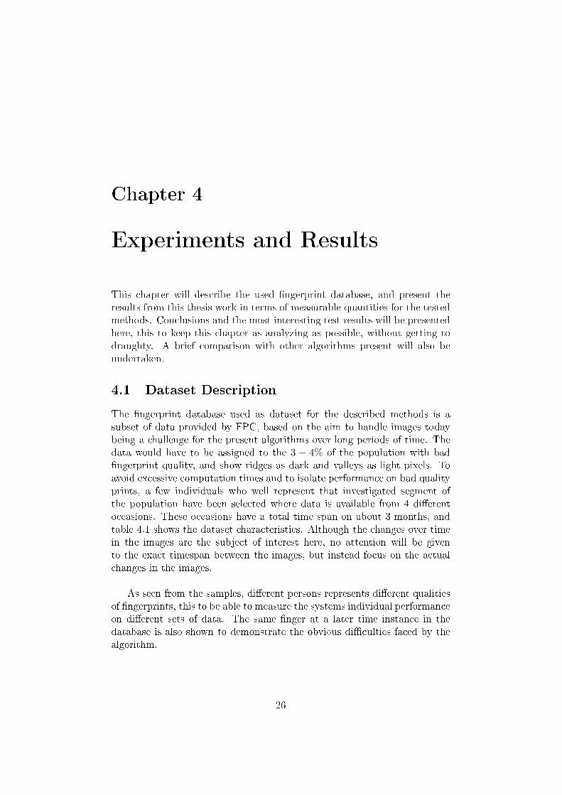
This chapter will describe the used ngerprint database, and present theresults from this thesis work in terms of measurable quantities for the testedmethods. Conclusions and the most interesting test results will be presentedhere, this to keep this chapter as analyzing as possible, without getting todraughty. A brief comparison with other algorithms present will also beundertaken.
4.1 Dataset Description
The ngerprint database used as dataset for the described methods is asubset of data provided by FPC, based on the aim to handle images todaybeing a challenge for the present algorithms over long periods of time. Thedata would have to be assigned to the 3 − 4% of the population with badngerprint quality, and show ridges as dark and valleys as light pixels. Toavoid excessive computation times and to isolate performance on bad qualityprints, a few individuals who well represent that investigated segment ofthe population have been selected where data is available from 4 dierentoccasions. These occasions have a total time span on about 3 months, andtable 4.1 shows the dataset characteristics. Although the changes over timein the images are the subject of interest here, no attention will be givento the exact timespan between the images, but instead focus on the actualchanges in the images.
As seen from the samples, dierent persons represents dierent qualitiesof ngerprints, this to be able to measure the systems individual performanceon dierent sets of data. The same nger at a later time instance in thedatabase is also shown to demonstrate the obvious diculties faced by thealgorithm.
26

Group Characteristic Value
Population Number of subjects 4Number of ngers per subject 6Number of images per nger 6Number of time instances 4Total number of images 576Timespan 80 days
Sensor Model Area Sensor FPC4010Measurement principle Reective capacitiveImage size 200 x 152 pixelsResolution 363 DPIPixel depth 8 bitsSensing area size 10.64 x 14.00 mm
Table 4.1: Characteristics of dataset
(a) Person#1
(b) Person#2
(c) Person #3 (d) Person#4
Figure 4.1: Samples from the ngerprint database at time instance 1
(a) Person#1
(b) Person#2
(c) Person #3 (d) Person#4
Figure 4.2: Samples from the ngerprint database at time instance 2, samengers
4.2 Results and Analysis
4.2.1 Segmentation
To evaluate the performance of the rst measurable step in the process, thesystem has been tested with the described dataset, and its performance has
27

been measured in the entity AI, Area Index, described in section 3.3.1.According to the Waterfall Masking method, the ngerprint database hasbeen evaluated over all time instants for each person, resulting in test resultsshown in table 4.2. High values indicates an image with large useable areas,with AI = 1.00 indicating no pixels being rejected as background materialat all.
Testperson AI Min Max
Person 1 (JS) 0.940 0.788 0.965Person 2 (JB) 0.759 0.604 0.874Person 3 (IM) 0.898 0.688 0.960Person 4 (CS) 0.883 0.663 0.942Average/low/high 0.87 0.60 0.96Time for calculation 12 secNumber of prints 144
Table 4.2: Test results for Waterfall Masking
Using Waterfall Masking resulted in a reliable quality measures for thepurpose, since it allowed large areas within the ngerprint that could beSC. We see that no print is all background information, which is reasonable,since it in every image should be some useful features present. Neither wasno image all perfect, which also reects reality.The method also allows large SC in images, without it being consideredbackground information, which is a required feature.What the method lacks though is the reliability when it comes to ngerprintimages with bad contact area in the middle of the image, as the one in g4.3. This was though considered a minor liability, since the present algorithmhandles "low contact percentage" images, i e an image as the one below wouldnever be allowed to enroll in the system.
Figure 4.3: Example on dicult image to segment, it being very misplaced onthe sensor
28

4.2.2 Secondary Crease Detection
The Quality Index, QI, determines how much area in the image is usable forDistinct Area Detection, i e grades background area and areas containingSC as bad areas. Studies of the results have shown that the method veryneatly marks the areas where SC may be present. A drawback though, isthat it seems to misinterpret ngerprint ridges and valleys as SC when theyget to wide. This is a drawback ascribed to the linear symmetry methodbeing applied in 3.3.2.Important to note with the deduced results in table 4.3 is that the QI
Testperson QI Min Max
Person 1 (JS) 0.723 0.561 0.759Person 2 (JB) 0.558 0.402 0.686Person 3 (IM) 0.695 0.458 0.772Person 4 (CS) 0.700 0.467 0.761Average/low/high 0.67 0.40 0.77Calculation time 314 secNumber of prints 144
Table 4.3: Test results for QI
includes both quality degrading due to background information (the AreaIndex), and due to unusable areas. That way, it can be trusted to only letthrough areas with clear linear patterns, which is what a regular algorithmneeds to extract a qualied template.
4.2.3 Feature Comparison
To evaluate the False Rejection Rate (FRR) and the False Acceptance Rate(FAR), tests have been run on the database, and individual values for allpersons have been recorded. This to be able to isolate types of ngerprintsthese methods handle better than others. From this data, general conclusionscan be drawn considering the usability of the methods proposed.
FRR
Tests were here run with two slightly dierent purposes:
• To test the inuence of maximum number of vectors, nLmax
This test rendered in best results (lowest FRR) for nLmax = 7, andrevealed quite a lot about the parameter dependencies; as nLmax in-creases, FRR is instantly decreasing, while as FAR increases some.This is natural, due to the matching algorithm; the odds of a template
29

Testperson Fails Tests FRR
Person 1 (JS) 387 642 60%Person 2 (JB) 379 648 58%Person 3 (IM) 219 648 34%Person 4 (CS) 459 648 71%Total 1444 2587 55%nLmax 7No of failed enrolls (FTE) 1(0.03%)Time for calculation 2h6m33s
Table 4.4: Total FRR over all time instances, 7 vectors
Testperson Fails Tests FRR
Person 1 (JS) 206 648 32%Person 2 (JB) 172 642 27%Person 3 (IM) 129 648 19%Person 4 (CS) 334 648 51%Total 841 2587 32%nLmax 20No of failed enrolls (FTE) 1(0.03%)Time for calculation 2h24m3s
Table 4.5: Total FRR over all time instances, 20 vectors
vector nding a "fake" counterpart in the candidate data increases asmore and more vectors exists in the candidate space.
• To test the performance over dierent time instances
The tests were run with template generation from the rst time in-stance, where after each template was compared to its responding n-ger at indicated time instance.
(a) Timeinstance 1
(b) Timeinstance 2
(c) Timeinstance 3
(d) Timeinstance 4
Figure 4.4: The same nger at the four time instances
30

Testperson Fails Tests FRR
Person 1 (JS) 85 210 40%Person 2 (JB) 55 216 25%Person 3 (IM) 50 216 23%Person 4 (CS) 65 216 30%Total 255 859 29%nLmax 20No of failed enrolls (FTE) 6(0.1%)Time for calculation 48m29s
Table 4.6: FRR for time instance 2, 20 vectors
Testperson Fails Tests FRR
Person 1 (JS) 86 216 39%Person 2 (JB) 79 216 37%Person 3 (IM) 27 216 12%Person 4 (CS) 87 216 40%Total 279 864 32%nLmax 20No of failed enrolls (FTE) 0(0.0%)Time for calculation 50m27s
Table 4.7: FRR for time instance 3, 20 vectors
Testperson Fails Tests FRR
Person 1 (JS) 84 216 39%Person 2 (JB) 141 216 65%Person 3 (IM) 31 216 14%Person 4 (CS) 86 216 40%Total 342 864 39%nLmax 20No of failed enrolls (FTE) 0(0.0%)Time for calculation 49m55s
Table 4.8: FRR for time instance 4, 20 vectors
The diering results shown in table 4.6-4.8 indicates a changing en-vironment (dry weather etc.) between the two time instances. Overthe whole time period, we see a successive increase in the total FRRvalue. This is natural, and what is interesting is that for test person #3, the value instead decreases over time, which inicts a good quality
31

template generation at time instance 1.The best total FRR, for all persons in the dataset, was 29%, which isvery high compared to a generic AFIS. Considering the dataset usedthough, the results would have to be considered rather good.
FAR
This measure is of less importance and is today a minor problem in the algo-rithms. The reason that this number is often very low in present algorithmsis the fact that it deals directly with spatial features in the image. In otherwords, an accidental "hit" on another nger is highly unbelievable. Thiscauses problems when working in another parameter space, since a lot of in-formation is lost in the process. The possibilities for two vectors accidentallymatching (within margins) between two dierent ngerprints is considerablygreater than two spatial areas looking the same.
Testperson Accepts Tests FAR
Person 1 (JS) 144 324 44%Person 2 (JB) 140 324 43%Person 3 (IM) 111 324 34%Person 4 (CS) 129 324 39%Total 524 1296 40%No of failed enrolls (FTE) 0(0.0%)Time for calculation 1h9m53s
Table 4.9: Total FAR
Very true, the tests rendered in values of FAR around 40% with the sameparameter settings as in the FRR-tests. This value is far greater than theaverage system ( 3 − 4% on an average dataset), but is of less importancesince prints of this bad quality are usually not even allowed to enter a system.
32

Chapter 5
Discussion
This chapter is meant to conclude the work performed during this thesis,and emphasize the meaning of the results by means of overall usability androbustness. Future possibilities for the work is also discussed.
5.1 Conclusion
The proposed system with a Gabor lter bank for detection of secondarycreases in ngerprint images described in this thesis is robust and has provento work well on the proposed dataset. The methods for comparison though,turned out to be a greater challenge. The transition from working in thespatial domain to a fabricated domain (r, θ) obviously generates a loss of in-formation to great to overcome. The recognized performance measure FRRis admittedly a few percent lower than present algorithms, while FAR is a lothigher for the proposed data. It should be noted once again, though, that thealgorithms in this thesis were never intended to replace today's, but insteadcomplement them where needed. Therefore, the traditional measures FRRand FAR may be a poor qualitative check for this developed vector compar-ison method, but are the admittedly most widely known quality measures inthe business.As for the detection of secondary creases, the material generated is a greathelp to existing algorithms, providing information about what areas in a n-gerprint images (bad or good quality) to avoid for Distinct Area Detection.An entity for this denition of a good quality ngerprint has also been set;the Quality Index.Overall, the work has shown that ngerprints normally avoided by nger-print recognition systems, can in fact possess features that are extractableand usable for verication purposes, and that those methods work betterthan traditional methods for that specic dataset.
33

5.2 Future Work
Due to the complexity of the system described, many parts of it can befurther optimized to t its purpose even better. However, from having de-veloped the system from scratch, the issues below would be prioritized infurther work.
Spatial Information On Vectors
Information about proles for each vectors could be stored to provide knowl-edge on where along the vector in the image the SC is detected to exist.
Matching Algorithm
Further investigation in optimal clustering and graph matching with adaptivethresholds in match scoring.
Improved Background Masking
Further development of the background masking algorithm to allow andidentify bad contact areas in ngerprint images.
34

Bibliography
[1] Federal Bureau of Investigation, The Science of Fingerprints:Classication and Uses, U.S. Government Printing Oce, WashingtonD.C., 1984
[2] Jain, A.K., L. Hong, S. Pankanti, and R. Bolle, AnIdentityAuthentication System Using Fingerprints, Proceedings of theIEEE, Vol. 85, No. 9, Sept. 1997, pp. 1365-1388.
http://citeseer.ist.psu.edu/jain97identity.html
[3] A. Roddy and J. Stosz, Fingerprint Features - Statistical Analysis andSystem Performance Estimates. Proceedings of IEEE, 85(9), pp.1390-1421, 1997.
http://citeseer.nj.nec.com/roddy99fingerprint.html (2004-11-05)
[4] Fingerprint Cards
http://www.fingerprint.se (2004-10-01, 2005-02-01)
[5] N. Petkov, P. Kruizinga, Nonlinear Operator for Oriented Texture,IEEE transactions on Image Processing, vol. 8, no. 10, October 1999
[6] A. Jain and S. Pankanti, Automated Fingerprint Identication andImaging Systems
http://citeseer.ist.psu.edu/453622.html (2004-10-26)
[7] Binaries for LATEXreport writing available on
http://www.math.aau.dk/~dethlef/Tips/download.html (2004-10-05)
and the client TeXnicCenter is available on
http://www.toolscenter.org/front_content.php?idcat=50 (2004-10-05)
35

[8] A. M. Bazen and S. H. Gerez, Directional Field Computation forFingerprints Based on the Principal Component Analysis of LocalGradients, Proceedings of the proRISC/IEEE workshop, November 30 December 1, 2000.
[9] K.W. Bowyer, P.J. Phillips, Empirical Evaluation Techniques inComputer Vision, The Institute of Electrical and ElectronicsEngineers, Inc., 1995, ISBN 0-8186-8401-1
[10] M. van Ginkel, C.L. Luengo Hendricks and L.J. van Vliet, A shortintroduction to the Radon and Hough transforms and how they relateto each other
http://www.ph.tn.tudelft.nl/~michael/mvanginkel_radonandhough_tr2004.pdf
(2004-10-07)
[11] Fingerprint Door locks Inc., Biometrics overview
http://www.fingerprintdoorlocks.com/info_biometrics.html (2005-01-10)
[12] N. Petkov, P. Kruizinga, Computational models of visual neuronsspecialised in the detection of periodic and aperiodic oriented visualstimuli: bar and grating cells, Biological Cybernetics 76, 83-96,Springer Verlag 1997
[13] R. Thai, Fingerprint Image Enhancement and Minutiae ExtractionSchool of Computer Science and Software Engineering, The Universityof Western Australia, 2003
[14] M. Sonka, V. Hlavac, R. Boyle, Image Processing, Analysis, andMachine Vision, 2nd. ed. PWS Publishing, 1998, ISBN 0-534-95393-X
36