experimental study of single and two-phase adiabatic flow
TRANSCRIPT

18ème Congrès Français de Mécanique Grenoble, 27-31 août 2007
1
Experimental study of single and two-phase adiabatic flow distribution in
compact heat exchangers.
Frédéric Poggi (a), Hélène Macchi-Tejeda (a), Alain Maréchal (b), Denis Leducq (a),
André Bontemps (b,c)
(a) Cemagref, GPAN, Parc de Tourvoie, BP 44,
Antony, 92 163, France
(b) CEA - GREThE, 17 avenue des martyrs,
Grenoble, 38 054, France
(c) Université Joseph Fourier, LEGI, 1021, rue de la piscine,
Saint Martin d’hères, 38 042, France
Corresponding author: [email protected]. Tel: + 33 1 40 96 61 21
Abstract: Small-channel heat exchangers are widely used for car air-conditioning. However information about
their behaviour remains scarce. An experimental device was built to characterize the distribution of
single and two-phase adiabatic flows in a small channel heat exchanger, and to measure its singular and
regular pressure losses. A transparent polycarbonate test section comprised a 16 mm diameter header
connected to 8 flat tubes with 7 small channels (Dh = 0.889 mm). Both were studied with horizontal flow
and vertical down-flow through the manifold. The mass flux range was between 15 and 650 kg/(m².s) in
the manifold and between 100 and 3 000 kg/(m².s) in the small channels. The range of vapour quality
values at the test section inlet was between 0.1 and 0.9. The two-phase refrigerant was condensed at the
outlet of each flat tube in order to measure each flow rate separately.
Résumé: Les échangeurs de chaleur compacts à mini-canaux sont largement répandus dans la climatisation
automobile. Cependant les informations sur leur comportement demeurent rares. Un dispositif
expérimental est réalisé pour caractériser la distribution des écoulements adiabatiques mono- et
diphasiques dans un échangeur compact à mini-canaux. Les pertes de pression singulières et régulières
sont mesurées. Une section d'essai en polycarbonate transparente comportant un distributeur de 16
millimètres de diamètre relié à 8 barrettes de 7 mini-canaux (Dh = 0.889 mm) est réalisée. Deux
configurations sont étudiées : écoulements horizontal et vertical descendant dans le distributeur. La
gamme de densité de flux massique varie de 15 à 650 kg/(m².s) dans le distributeur et de 100 à 3 000
kg/(m².s) dans les mini-canaux. Les valeurs de titre en vapeur en entrée de section d'essai sont comprises
entre 0,1 et 0,9. Le réfrigérant diphasique est condensé en sortie de chaque barrette afin de mesurer
chaque débit séparément.
Key-words: Distribution ; compact heat exchanger ; small channel ; pressure drop 1 Introduction
The study described in this paper answers a triple objective: - Environmental objective: reduction of the refrigerant charge of refrigerating systems
thanks to the implementation of small-channel heat exchangers (protocols of Montreal [1987] and Kyoto [1997]),
- Industrial objective: the studied exchanger is similar to automobile air-conditioners or plate heat exchangers for cooling fuel cells,

18ème Congrès Français de Mécanique Grenoble, 27-31 août 2007
2
- Scientific objective: to fulfil the lack of data and models concerning distribution and singular pressure drops on millimetre scale tubes.
Thus, this work experimentally studies a portion of small-channel heat exchanger with liquid single-phase flow and two-phase flow. The selected geometry is that of the automobile's equipments (FIG. 1). A manifold distributes the refrigerant in the small channels of 8 successive extruded flat tubes in two positions (horizontal flow and vertical down-flow in the manifold). This geometry can be industrially manufactured by fitting together the flat tube inlets inside the manifold by a protrusion. The tube protrusion depth into the manifold will also affect the distribution. Webb and al. (2004) and Hrnjak (2004) provided recent reviews on this subject. In this paper, we studied the refrigerant distribution; regular and singular pressure drops in the small-channels and along the distributor were also studied by Poggi and al. (2007), but are not presented in this paper.
FIG. 1 – Distributor for small-channel heat exchangers used in industrial applications.
2 Experimental device
2.1 General description
The FIG. 2 describes the experimental device. It consists of 4 main loops:
− The evaporation loop: providing vapour quality at the inlet of the test section, − The test loop: including the test section, − The condensation loop: providing heat balance at the outlet of the test section, − The subcooling loop: to avoid pump's cavitations in the test loop.
A Wafer-Mag Brooks electromagnetic and a Danfoss Mag 1100 flowmeters were
respectively used to measure the mass flow rate in evaporation (∆+/- 0.020% of mass flow rate) and condensation (∆+/- 0.033% of mass flux) loops. The vapour quality was set at the inlet of the test section thanks to the evaporation loop. In the test loop, all tubes were well insulated in order to consider the flow as adiabatic. A special attention was given in a device design and manufacturing in order to minimize instabilities in the whole loop, especially for the two-phase flow.
8 flat tubes
Refrigerant input
8 flat tubes
Manifold
Manifold
Refrigerant input
Vertical down-flow through the manifold
Manifold
Horizontal flow through the manifold
multi-port flat tube (7 small-channels)

18ème Congrès Français de Mécanique Grenoble, 27-31 août 2007
3
Evaporation loop
T
Condensers (8)
T
T
T
p
T
T
TT
pTT
∆p
1
2
3
4
5
6
7
8
9
∆p
∆p
Test loop
Condensation loop
Subcooling loop
Test section
Evaporation loop
T
Condensers (8)
T
T
T
p
T
T
TT
pTT
∆p
1
2
3
4
5
6
7
8
9
∆p
∆p
Test loop
Condensation loop
Subcooling loop
Test section
1 Flowmeter (Evaporation loop)2 Pump (Test loop)3 Bypass Valve 4 Control Valve5 Flowmeter (Test loop)
T Temperature sensorP Pressure sensor∆P Differential pressure sensor
6 8 flowmeters (Test loop)7 Flowmeter (Condensation loop)8 8 Flowmeters (Condensation loop)9 Control Valve (Condensaion loop)
FIG. 2 – The experimental device.
2.2 Test section
The test section was built in polished polycarbonate in order to visualise the flows in the
manifold and in the small channels. The manifold diameter is 16 mm with a 90 mm length; 8 multi-port flat tubes are inserted inside the manifold. Each flat tube contains 7 rectangular small channels (Dh = 0.889 mm) (FIG. 1, 3). The refrigerant HFE-7100 was used in order to carry out experiments close to atmospheric pressure and ambient temperature.
Plug
Thermocouples
Refrigerant input
Manifold
Pressure hold
Refrigerant outletto condensers and flowmeters
8 parallel flat
tubes
Manifold
Parallel flat tubes
Manifold
Horizontal flow through the manifold
Vertical down-flow through the manifold
FIG. 3 – Representation and photographs of the test section.
The instrumentation allows the measurement of the flow rate and the vapour quality at the outlet of each multi-port flat tube. The distribution of the flow rate in the manifold can be determined as a function of the inlet vapour quality and total flow rate. A Danfoss Mass 2100 mass flowmeter (∆+/- 0.033%) was installed at the inlet of the test section. The temperature was measured with a platinum resistance sensor (∆+/- 0.3%) and the pressure was measured with an absolute pressure sensor Rosemount 0/2 bars (∆+/- 0.2%). At the outlet of the test section, 8 plate condensers were placed for each flat tube (link between 200 and 300 loops). Both the inlet
18ème Congrès Français de Mécanique Grenoble, 27-31 août 2007
4
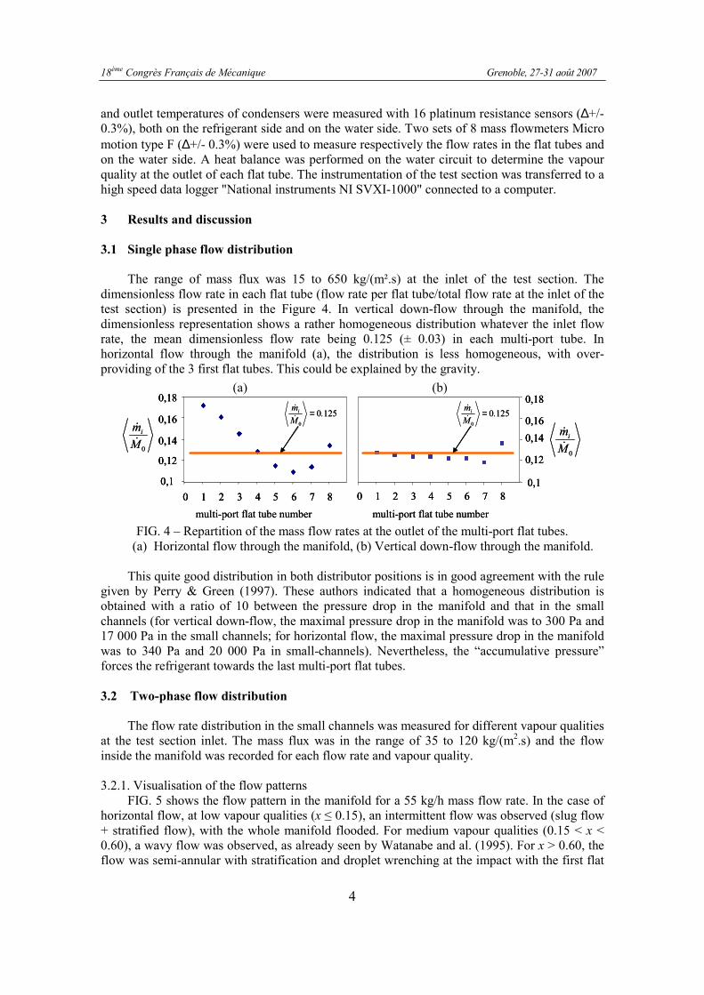
and outlet temperatures of condensers were measured with 16 platinum resistance sensors (∆+/- 0.3%), both on the refrigerant side and on the water side. Two sets of 8 mass flowmeters Micro motion type F (∆+/- 0.3%) were used to measure respectively the flow rates in the flat tubes and on the water side. A heat balance was performed on the water circuit to determine the vapour quality at the outlet of each flat tube. The instrumentation of the test section was transferred to a high speed data logger "National instruments NI SVXI-1000" connected to a computer.
3 Results and discussion
3.1 Single phase flow distribution
The range of mass flux was 15 to 650 kg/(m².s) at the inlet of the test section. The
dimensionless flow rate in each flat tube (flow rate per flat tube/total flow rate at the inlet of the test section) is presented in the Figure 4. In vertical down-flow through the manifold, the dimensionless representation shows a rather homogeneous distribution whatever the inlet flow rate, the mean dimensionless flow rate being 0.125 (± 0.03) in each multi-port tube. In horizontal flow through the manifold (a), the distribution is less homogeneous, with over-providing of the 3 first flat tubes. This could be explained by the gravity.
0M
mi
&
&
multi-port flat tube number
0M
mi
&
&
multi-port flat tube number
0 1 2 3 4 5 6 7 8
0,1
0,12
0,14
0,16
0,18
0,1
0,12
0,14
0,16
0,18
0 1 2 3 4 5 6 7 8
12500
.M
mi =&
&1250
0
.M
mi =&
&
0M
mi
&
&
multi-port flat tube number
0M
mi
&
&
multi-port flat tube number
0 1 2 3 4 5 6 7 8
0,1
0,12
0,14
0,16
0,18
0 1 2 3 4 5 6 7 8
0,1
0,12
0,14
0,16
0,18
0,1
0,12
0,14
0,16
0,18
0 1 2 3 4 5 6 7 80,1
0,12
0,14
0,16
0,18
0 1 2 3 4 5 6 7 8
12500
.M
mi =&
&1250
0
.M
mi =&
&
FIG. 4 – Repartition of the mass flow rates at the outlet of the multi-port flat tubes. (a) Horizontal flow through the manifold, (b) Vertical down-flow through the manifold.
This quite good distribution in both distributor positions is in good agreement with the rule
given by Perry & Green (1997). These authors indicated that a homogeneous distribution is obtained with a ratio of 10 between the pressure drop in the manifold and that in the small channels (for vertical down-flow, the maximal pressure drop in the manifold was to 300 Pa and 17 000 Pa in the small channels; for horizontal flow, the maximal pressure drop in the manifold was to 340 Pa and 20 000 Pa in small-channels). Nevertheless, the “accumulative pressure” forces the refrigerant towards the last multi-port flat tubes.
3.2 Two-phase flow distribution
The flow rate distribution in the small channels was measured for different vapour qualities at the test section inlet. The mass flux was in the range of 35 to 120 kg/(m2.s) and the flow inside the manifold was recorded for each flow rate and vapour quality.
3.2.1. Visualisation of the flow patterns
FIG. 5 shows the flow pattern in the manifold for a 55 kg/h mass flow rate. In the case of horizontal flow, at low vapour qualities (x ≤ 0.15), an intermittent flow was observed (slug flow + stratified flow), with the whole manifold flooded. For medium vapour qualities (0.15 < x < 0.60), a wavy flow was observed, as already seen by Watanabe and al. (1995). For x > 0.60, the flow was semi-annular with stratification and droplet wrenching at the impact with the first flat
(b) (a)

18ème Congrès Français de Mécanique Grenoble, 27-31 août 2007
5
tube. For the higher vapour quality (x = 0.85), an annular flow was observed before the impact of the fluid with the first flat tube; then the droplet wrenching led to fog formation. In the case of vertical down-flow, for all vapour qualities, we observed an annular flow with liquid accumulation at bottom. All the higher then the inlet vapour quality was low. On the contrary, the thickness of the annular liquid film decreased as the quality increase. Furthermore the gravity effect amplified both the thinning of the liquid film in annular down-flow before the impact of the fluid on the first flat tube and the liquid accumulation in the rear of the manifold. Droplet wrenching was also observed when the fluid impacted the first flat tube; when the vapour quality increased, the droplet wrenching led to fog formation.
1 2 3 4 5 6 7 8
Flow direction
1 2 3 4 5 6 7 8
Flow direction
1 2 3 4 5 6 7 8
Flow direction
A : xin = 15% B : xin = 30% C : xin = 45% D : xin = 75% E : xin = 90%
A
B
C
D
EA B C D E
1
2
3
4
5
6
7
8
Flo
w d
irectio
n
1
2
3
4
5
6
7
8
Flo
w d
irectio
n
1
2
3
4
5
6
7
8
FIG. 5 – Photograph of the flow patterns in the manifold for a 55 kg/h mass flow rate and various inlet vapour qualities for both positions (a) horizontal flow (b) vertical down-flow
through the manifold.
3.2.2. Influence of the inlet vapour quality on the distribution FIG. 6 shows the liquid and vapour dimensionless mass flow rates in the 8 multi-port flat
tubes for both horizontal flow and vertical down-flow through the manifold in adiabatic condition for a 55 kg/h mass flow rate. In the case of horizontal flow, the liquid dimensionless mass flow rate had a quite high value for the first channel because of gravity. Then, the liquid dimensionless mass flow rate gradually decreased as the channel number increased, excepted for the last flat tube. Indeed the “accumulative pressure” forces the liquid towards the last flat tubes. The vapour dimensionless mass flow rate showed an opposite trend, especially for the low vapour qualities. When the inlet vapour quality increased, the liquid dimensionless mass flow rate decreased strongly in the first flat tube, but increased lightly in the last flat tube, so that the distribution tends to be more homogeneous. In the vertical down-flow case, the liquid dimensionless mass flow rate also decreased as the channel number increased, further on the liquid dimensionless mass flow rate highly increased under the “accumulative pressure” forcing the liquid towards the last flat tube, effect amplified by the gravity. The vapour dimensionless mass flow rate increased lightly as the channel number increased, excepted the two last flat tube because of the liquid accumulation at the manifold bottom. Otherwise, for both manifold positions, the variation of vapour distribution was much less significant than that of the liquid.

18ème Congrès Français de Mécanique Grenoble, 27-31 août 2007
6
FIG. 6 – Dimensionless vapour quality for each flat tube for various inlet vapour qualities and
an inlet mass flow rate of 0M& = 55 kg/h for both positions (a) horizontal (b) vertical down-flow.
4 Conclusions
Flow distribution in small channels of compact heat exchanger has been experimentally studied. In single-phase flows, the distribution did not depend on the inlet mass flow rate and it was rather homogeneous in both configurations. However it was less homogeneous in the horizontal flow than in the vertical one because of gravity. In two-phase flows, for the horizontal position, the flow patterns depended on the inlet vapour quality. On the contrary, in the vertical position, the flow at the manifold inlet was always annular, whatever the inlet vapour quality. As for the distribution, it was significantly affected by the manifold orientation and the inlet vapour quality. When the inlet vapour quality increased, the phase distribution was more homogeneous. References
Hrnjak, P., 2004, Flow distribution issues the parallel flow heat exchangers, ASHRAE annual meeting, AN-04-1-2.
Perry R.H., Green P.W., 1997, Chemical Engineers Handbook, Mc Graw-Hill.
Poggi, F., Macchi-Tejeda, H., Maréchal, A., Leducq, D., Bontemps A., 2007, Single and two-phase adiabatic flow distribution and pressure losses in small-channel heat exchanger, Int. conf. Heat SET 2007, Chambéry, France.
Poggi, F., Macchi-Tejeda, H., Maréchal, A., Leducq, D., Bontemps, A., 2007, Etude expérimentale : Distribution d’écoulements mono- et diphasiques et pertes de pression dans un échangeur à mini-canaux, Congrès SFT 2007, Île des Embiers, France.
Watanabe, M., Katsuda, M., Nagata, K., 1995, Two-phase flow distribution in multi-pass tube modelling serpentine type evaporator, ASME/JSME Thermal Engineering. Conf. 2, 35–42.
Webb, R.L., Chung, K., 2004, Two-phase flow distribution in tubes of parallel flow heat exchangers, Heat Transfer Engineering, 26, 3-18.
Liquid
Flat tube number
Liquid
Flat tube number
l
l,i
M
m
0&
& l
l,i
M
m
0&
&
v
v,i
M
m
0&
& v
v,i
M
m
0&
& Vapour Vapour
(a) (b)
Flat tube number Flat tube number