experimental study of seismic qualification of … study of seismic qualification of incabinet...
TRANSCRIPT

Experimental Study of Seismic Qualification of Incabinet Equipment in NPP Fan-Ru Lin, Juin-Fu Chai, Zih-Yu Lai , K. C. Chang NCREE (National Center for Research on Earthquake Engineering), Taiwan W.I. Liao, Pai-Fang Chou NTUT (National Taipei University of Technology), Taiwan Chin-Cheng Huang INER (Institute of Nuclear Energy Research), Taiwan SUMMARY: (10 pt) In order to establish reasonable seismic demands to safety-related electrical instrument mounted on electrical cabinets (referred to as incabinet equipment), one existing cabinet used in NPP3 was adopted as the specimen in the shaking table test to understand the basic characteristics of dynamic response for electrical cabinets. The vibration responses and spectral amplification factors of the tested cabinet under different shaking intensity levels as well as the variation of total mass and anchorage locations of additional weight attached on the cabinet were studied and summarized in the study. The results of this preliminary study can be contributed to propose the complete test plan for the identified MCC for NPP4 in future studies. Keywords: Seismic qualification, Incabinet response spectrum 1. INTRODUCTION Under consideration for M/E system maintenance in nuclear power plants (NPP), thousands of operational or safety-related equipment might be replaced during NPP long term operation. To maintain post-earthquake function of safety-related system in NPP, seismic qualification of associated equipment should be submitted by equipment manufacturer before installation. For NPP equipment mounted on floor slab, floor response spectra are used to define the seismic demand on equipment in seismic qualification testing or analysis. However, for seismic demand at the mounting point location of incabinet electrical instrument, dynamic amplification effects of cabinet should be considered as well. Executing shaking table testing is the straightest way to evaluate cabinet amplification effects to incabinet equipment. Detailed finite element analysis is also useful associated with micro vibration in-situ measurement verification. However, a practical and cost-effective evaluation method for incabinet equipment is needed considering that both testing and finite element analysis are complex and costly. The objective of this 3-year project is to develop reasonable design mechanism of seismic demand for incabinet instruments belonging to safety-related M/E systems in NPP. Based on the Final Safety Analysis Report (FSAR, General Electric Co, 2007) for Lungmen nuclear power plant (NPP4), the RHR C system was chosen due to the importance to the critical M/E system causing the reactor core damage accident (Fig. 1.1). The associated MCC (Motor Control Center) cabinets were identified as the target cabinets in this project (Fig. 1.2). For seismic demand on incabinet equipment, as floor response spectrum represents the seismic demand at the base of the cabinet, so is incabinet response spectrum (ICRS) to incabinet equipment. Two kinds of simplified concepts are mainly used to obtain ICRS. The first concept is using floor response spectrum multiplied by incabinet amplification factors (AF). The second concept is to generate ICRS directly by simulated cabinet models with simplified modal shapes and mathematical functions. In the first concept, U.S. Department of Energy (DOE, 1997) proposed that ICRS can be computed by scaled floor response spectrum multiplied by incabinet amplification factor, which is

Step 1 Using the seismic main event tree corresponding to top three accident sequences of core damage risk to find out the scenario of station blackout.
tabulated corresponding to the type of cabinet and statistically calculated from Seismic Qualification Utility Group (SQUG) data base. According to physical testing results, Merz and Ibanez (1990) proposed that effective amplification factor of 3.0 can be used for MCC cabinets, whereas 6.0 is for flexible panels. From above, the same amplification ratio is used for all spectral acceleration in the intrested frequency range and might cause too conservative seismic demands for incabinet equipment. Shi (1997) proposed a more detailed method to modify amplification factors by general principles of modal response analysis and given significant natural frequencies of the specified cabinet and attached floor. In the second concept, based on the observation of finite element analysis results that the response of a particular mounting point location of incabinet equipment can be represented by one or two significant modes, Gupta (1999) proposed that ICRS can be generated by one local or both local and global modes using Rayleigh-Ritz method. Yang (2001) implemented and modified the Ritz-vector approach to establish a computer program evaluating cabinet dynamic characteristics effectively, and to calculate ICRS according to limited information on cabinet property. For the pilot research on ICRS in the first year of project, dynamic characteristics of cabinets were further realized through experimental study. One existing cabinet used in NPP3 was adopted as the test specimen in the shaking table test. Although structural characteristics of the tested cabinet did not correspond with MCC cabinets in NPP4, application of the amplification factors suggested by above shaking table test results was preliminary studied. The influence of parameters to ICRS, i.e. incabinet equipment mass and types of attached cabinet component, were discussed as well.
Figure 1.1. The critical M/E system and components determination flow chart
Figure 1.2. MCC cabinets belonging to RHR C system in NPP4
Step 2 Using seismic event tree corresponding to the scenario of station blackout to find out the M/E system that effect the core damage accident.
Step 3 Using seismic fault tree corresponding to the specified M/E system to find out the components that might be damaged.
Step 4 Using the risk achievement worth (RAW) and median value of seismic capacity(Am) to identify the critical components causing the reactor core damage accident.

2. TEST CONFIGURATION 2.1. Test Specimen and Measurement The test specimen is 228.5 cm high, 65.5 cm wide, 192.5 cm deep and approximately weighs 450 kg. As shown in Fig. 2.1 and Table 2.1, the original structure and inside configuration of the specimen are not totally symmetric. According to the anchorage condition of MCC cabinets in NPP4, the specimen was anchored onto two channels by M12 hex-head bolts, and the channels were welded to the adapter steel plate (Fig. 2.2). Most of incabinet equipment is attached to frames, vertical plates or horizontal shelves. In this test, the incabinet equipment was simulated by mass blocks up to 40 kg, and the blocks were fixed to vertical plates or horizontal shelves by bolts and connection plates. Due to the stroke limitation in the Y direction of shaking table, the weak axis of cabinet was along to the X axis of table. Measurement points were allocated to study the dynamic characteristics of the specimen (Table 2.1). There were total 31 accelerometers and 22 linear variable differential transformers (LVDT) arranged to investigate significant global modes and local modes which were provided by flexible panels and shelves. In addition, several accelerometers were arranged at the incabinet equipment (mass blocks) in the out-of-plane direction of the attached panels and shelves to study the properties of ICRS. 2.2. Test Procedure Testing items and associated input motion are shown in Table 2.2. The shaking table tests were divided into three groups: the original cabinet (Test 1), the cabinet with horizontally placed incabinet equipment (Test 2), and the cabinet with vertically hanging incabinet equipment (Test 3). The purpose of Test 1 is to investigate elastic and inelastic seismic behavior of the original equipment.
(a) testing configuration (b) part A (c) part B
Figure 2.1. Test specimen
(a) anchorage of NPP4 Cabinet (b) Test specimen
Figure 2.2. Anchorage of Test specimen
Z X
Y N
A B
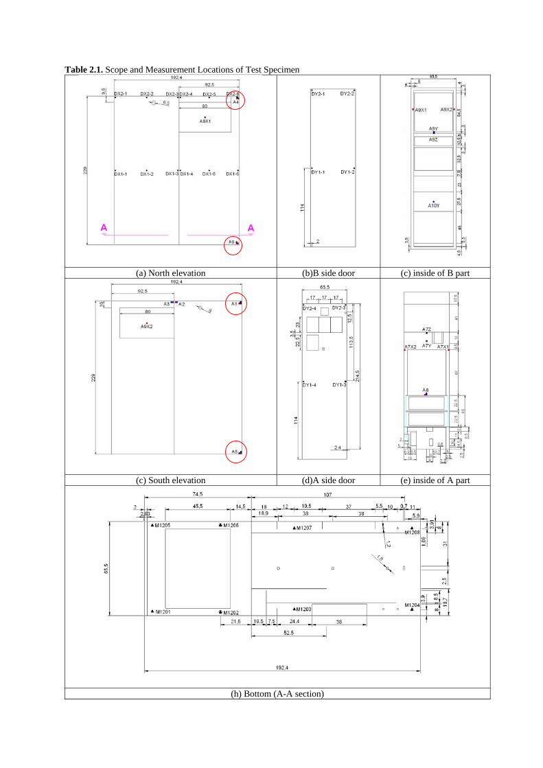
Table 2.1. Scope and Measurement Locations of Test Specimen
(a) North elevation (b)B side door (c) inside of B part
(c) South elevation (d)A side door (e) inside of A part
(h) Bottom (A-A section)

On the other hand, Test 2 and Test 3 were to study the effects of weight and installation types of incabinet equipment to ICRS. The testing cases of uni-axial swept sine wave tests (for both pre- and post-tests) and a set of tri-axial artificial motion test (Table 2.2) were implemented for each testing item. As shown in Fig. 2.3, considering that the purpose of this study is to obtain dynamic behavior of electrical cabinets, a generic required response spectrum (RRS) proposed by IEEE693 (2006) was used to ensure that basic characteristics of tested cabinet can be obtained by testing results excluding the effects of variability in different sites and building structures. In Test 2 and Test 3, up to 50 percent intensity of artificial motion was used to maintain the cabinet structure in elastic behavior. In the final stage of the testing, to investigate the inelastic behavior of the specimen, artificial motion in X direction was scaled to 2.0g approximately. Table 2.2. Test Program
Testing items mass block weight (kgf) A-side B-side Test name N-dir. S-dir. N-dir. S-dir.
Test 1 - - - - Test 2-1 20 20 Test 2-2 0 20 Test 2-3 0 40 Test 2-4 40 40 Test 2-5 40 0 Test 2-6 20 0 Test 3-1 20 0 20 0 Test 3-2 20 20 20 20 Test 3-3 0 20 0 20 Test 3-4 10 10 10 10 Test 3-5 40 0 40 0 Test 3-6 0 40 0 40 Test 3-7 40 40 40 40
Testing cases X-dir. (NS)
Y-dir. (EW)
Z-dir. (V) Input
Motion PA (g)
PA (g)
PA (g)
Duration(sec)
Sweep sine-X
0.05 - - 300
Sweep sine-Y
- 0.05 - 300
Sweep sine-Z
- - 0.05 300
IEEE693 artificial motion (ZPA) 0.5g_25% 0.125 0.125 0.1 45 0.5g_50% 0.25 0.25 0.2 45 0.5g_75% 0.375 0.375 0.3 45 0.5g_100% 0.5 0.5 0.4 45 0.5g_150% 0.75 0.75 0.6 45 0.5g_200% 1 1 0.8 45 0.5g_400% 2 1 0.8 45
X dir.
Y dir.
Z dir.
0 10 20 30 40-0.8
-0.6
-0.4-0.2
0
0.2
0.4
0.60.8
Time (sec)
Acc
. (g)
0 10 20 30 40-0.8
-0.6
-0.4
-0.2
0
0.20.4
0.60.8
Time (sec)
Acc
. (g)
0 10 20 30 40-0.8
-0.6
-0.4-0.2
0
0.20.4
0.60.8
Time (sec)
Acc.
(g)
0.5
1
1.52
345
Frequency (Hz)
SA
(g)
501.1 8.0 33 501.1 8.0 33 501.1 8.0 33
0.5
1
1.52
345
Frequency (Hz)
SA
(g)
501.1 8.0 33 501.1 8.0 33 501.1 8.0 33
0.5
1
1.52
345
Frequency (Hz)
SA
(g)
501.1 8.0 33 501.1 8.0 33 501.1 8.0 33
Figure 2.3. IEEE693 artificial motion and corresponding Test Response Spectrum (TRS)

3. TEST RESULTS 3.1. Dynamic Characteristics Natural frequencies of global modes of the cabinet were obtained from transfer functions determined by the signals measured at top points A1, A4 with respect to bottom points A5, A6 for parts A and B, respectively (Table 2.1). The fundamental frequencies of the cabinet with no incabinet equipment were shown in Table 3.1 and Fig. 3.1. It can be observed that the fundamental frequency in X or Y direction will gradually reduce as the shaking intensity of input motion increases,. However, the distribution of frequency contents changed slightly after resisting 400 percent intensity of artificial motion in X direction. Comparing the transfer function under different installation type of incabinet equipment as shown in Fig. 3.2 and Fig. 3.3, the frequency contents of vertical hanging type obviously changed a lot since the global mode of this test specimen was primarily contributed by the response of vertical plates, where the simulated incabinet equipment attached in Test 3. Table 3.1. Fundamental Frequencies of the Cabinet
Post-test Freq.(Hz) Dir. Pre-test 0.5g_50% 0.5g_200% 0.5g_400%
X 10.29 9.97 9.49 8.06 Y 19.52 19.36 18.56 16.33
Figure 3.1. Transfer functions of Test 1 (w/o incabinet equipment)
Figure 3.2. Transfer functions of Test 2-4 (w/ horizontal placed equipment)
Figure 3.3. Transfer functions of Test 3-7 (w/ vertical hanging equipment)
5 10 15 20 25 30 35 40
2
4
6
8
10
12
14
Frequency (Hz)
TR
A側B側
A part B part
5 10 15 20 25 30 35 40
2
4
6
8
10
12
14
Frequency (Hz)
TR
A側B側
A part B part
5 10 15 20 25 30 35 40
2
4
6
8
10
12
14
Frequency (Hz)
TR
A側B側
A part B part
5 10 15 20 25 30 35 40
2
4
6
8
10
12
14
Frequency (Hz)
TR
A側B側
A part B part
5 10 15 20 25 30 35 40
2
4
6
8
10
12
14
Frequency (Hz)
TR
A側B側
A part B part
5 10 15 20 25 30 35 40
2
4
6
8
10
12
14
Frequency (Hz)
TR
A側B側
A part B partPre-test in X direction Post-test in X direction
X direction Y-direction
X direction Y-direction
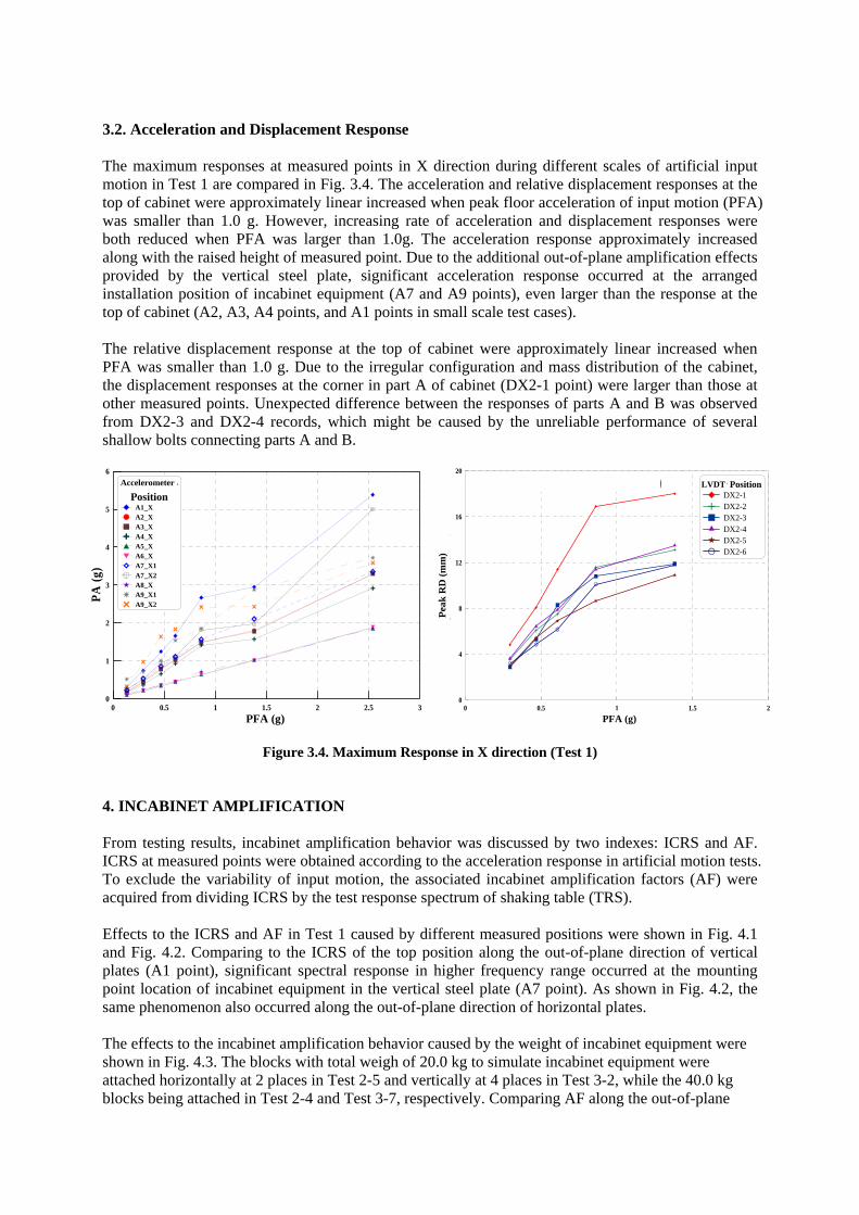
3.2. Acceleration and Displacement Response The maximum responses at measured points in X direction during different scales of artificial input motion in Test 1 are compared in Fig. 3.4. The acceleration and relative displacement responses at the top of cabinet were approximately linear increased when peak floor acceleration of input motion (PFA) was smaller than 1.0 g. However, increasing rate of acceleration and displacement responses were both reduced when PFA was larger than 1.0g. The acceleration response approximately increased along with the raised height of measured point. Due to the additional out-of-plane amplification effects provided by the vertical steel plate, significant acceleration response occurred at the arranged installation position of incabinet equipment (A7 and A9 points), even larger than the response at the top of cabinet (A2, A3, A4 points, and A1 points in small scale test cases). The relative displacement response at the top of cabinet were approximately linear increased when PFA was smaller than 1.0 g. Due to the irregular configuration and mass distribution of the cabinet, the displacement responses at the corner in part A of cabinet (DX2-1 point) were larger than those at other measured points. Unexpected difference between the responses of parts A and B was observed from DX2-3 and DX2-4 records, which might be caused by the unreliable performance of several shallow bolts connecting parts A and B.
0 0.5 1 1.5 2 2.5 3PGA ( )
0
1
2
3
4
5
6
PA (g
)
AccelemeterPosition
A1_XA2_XA3_XA4_XA5_XA6_XA7_X1A7_X2A8_XA9_X1A9_X2
Figure 3.4. Maximum Response in X direction (Test 1)
4. INCABINET AMPLIFICATION From testing results, incabinet amplification behavior was discussed by two indexes: ICRS and AF. ICRS at measured points were obtained according to the acceleration response in artificial motion tests. To exclude the variability of input motion, the associated incabinet amplification factors (AF) were acquired from dividing ICRS by the test response spectrum of shaking table (TRS). Effects to the ICRS and AF in Test 1 caused by different measured positions were shown in Fig. 4.1 and Fig. 4.2. Comparing to the ICRS of the top position along the out-of-plane direction of vertical plates (A1 point), significant spectral response in higher frequency range occurred at the mounting point location of incabinet equipment in the vertical steel plate (A7 point). As shown in Fig. 4.2, the same phenomenon also occurred along the out-of-plane direction of horizontal plates. The effects to the incabinet amplification behavior caused by the weight of incabinet equipment were shown in Fig. 4.3. The blocks with total weigh of 20.0 kg to simulate incabinet equipment were attached horizontally at 2 places in Test 2-5 and vertically at 4 places in Test 3-2, while the 40.0 kg blocks being attached in Test 2-4 and Test 3-7, respectively. Comparing AF along the out-of-plane
0 0.5 1 1.5 2
PGA (g)0
4
8
12
16
20
Dis
plac
emen
t (m
m)
Meter PositionDX2-1DX2-2DX2-3DX2-4DX2-5DX2-6
Top Displacement(Test 1-X dir.)
PFA (g)
Pea
k R
D (m
m)
LVDT
PFA (g)
Accelerometer

direction in different installation types, spectral responses in higher frequency range decreased dramatically with rising weight of incabinet equipment, while the AF at the horizontal plate was slightly changed from Test 2-5 to Test2-4. It can be seen that the effect of incabinet equipment was larger to AF at vertical plate than the one at horizontal plate.
10-1
100
101
102
10-2
10-1
100
101
Response spectrum-A1X
Frequency (Hz)
Spe
ctra
l Res
pons
e Ac
cele
ratio
n (g
)
IEEE693-0.5g(100%)IEEE693-0.5g(150%)IEEE693-0.5g(200%)
10-1
100
101
102
10-2
10-1
100
101
Response spectrum-A7X2
Frequency (Hz)S
pect
ral R
espo
nse
Acce
lera
tion
(g)
IEEE693-0.5g(100%)IEEE693-0.5g(150%)IEEE693-0.5g(200%)
Figure 4.1. ICRS of different measured positions (in X direction)
10-1
100
101
102
10-3
10-2
10-1
100
101Response spectrum-A1Z
Frequency (Hz)
Spe
ctra
l Res
pons
e Ac
cele
ratio
n (g
)
IEEE693-0.5g(100%)IEEE693-0.5g(150%)IEEE693-0.5g(200%)
10
-110
010
110
2
10-3
10-2
10-1
100
101Response spectrum-A7Z
Frequency (Hz)
Spe
ctra
l Res
pons
e Ac
cele
ratio
n (g
)
IEEE693-0.5g(100%)IEEE693-0.5g(150%)IEEE693-0.5g(200%)
Figure 4.2. ICRS of different measured positions (in Z direction)
10-1 100 101 1020
1
2
3
4
5Amplification Factor-A7Z
Frequency (Hz)
AF
Test2-6(20kg)Test2-5(40kg)Test2-4(80kg)
10-1 100 101 1020123456789
101112131415
Amplification Factor-A9X2
Frequency (Hz)
AF
Test3-4(40kg)Test3-2(80kg)Test3-7(160kg)
Figure 4.3. AF of mounting point location in the out-of-plane direction

(a) X-direction (b) Y-direction
(c) Z-direction (d) Total
Figure 4.4. Amplification factor distribution From above analysis results, the histogram of peak AF at measured points in all artificial motion tests were shown in Fig. 4.4. According to the statistical results, the value of peak AF is between 3.5 and 5.5 in weak axis of the cabinet, as well as between 3.5 and 4.5 in strong axis. Most peak AF in vertical direction was between 1.5 and 3.5, and obviously smaller than most peak AF values in horizontal direction. In rough approximation, the average of total peak AF values is about 3.54. Multiplying by the reduction factor 0.6 considering uncertainty of narrow-band response spectra (Merz 1990), the effective AF of this test is 2.12, which is smaller than the suggested values of DOE’s study (1997). On the other side, the zero period acceleration (ZPA) of ICRS at the top of cabinet in artificial motion tests were in the range of 1.5 to 3.0 times of the ZPA of TRS in weak axis of the cabinet, and between 1.0 and 1.7 times in both strong axis and vertical direction. In ASCE7-10 (ASCE 2010), the component amplification factor (ap) of MCC or other cabinets composed by sheet metal framing is 2.5, which is also applicable to flexible equipment with fundamental frequency smaller than 16.6 Hz. Comparing to ASCE7-10, several amplification at the top of cabinet along weak axis were slightly larger the suggested ap value. 5. CONCLUSIONS In order to establish simplified design method of incabinet response spectra (ICRS), a preliminary experimental study was completed in the first year of this project. Corresponding to the previous studies (Abhinav et al. 1999, Yang et al. 2001), significant spectral response in higher frequency range contributed by local components was observed at the mounting point location of incabinet equipment. However, different weight and its distribution of incabinet equipment may influence ICRS, especially

for those anchored at vertical sheet metal plates. Comparing to the elastic behavior of the cabinet in shaking table tests, the effective amplification factor suggested by DOE study (1997) might be a little conservative, while the component amplification factor in ASCE 7-10 is suitable to establish the ZPA of ICRS. AKCNOWLEDGEMENT This support of the National Science Council (NSC) under the Grants NSC101-3113-P042A-004 is gratefully acknowledged. REFERENCES General Electric Co. (2007). FSAR of Lungmen Nuclear Power Station Units 1&2, Appendix AC: Seismic
Analysis, Aug. 15, 2007, USA. U.S. Department of Energy (DOE). (1997). Seismic evaluation procedure for equipment in U.S. Department of
Energy facilities, DOE/EH-0545, USA. K.L. Merz and P. Ibanez, ANCO Engineers, Inc. (1990). Guidelines for estimation of cabinet dynamic
amplification, Nuclear Engineering and Design, vol. 123, p.p. 247-255, North-Holland. Shi Z.T., Raytheon Engineers and Constructors. (1997). A simplified approach to generate in-cabinet amplified
response spectrum , Transactions of the 14th International Conference on Structural Mechanics in Reactor Technology (SMiRT 14), Lyon, France.
Abhinav Gupta, S.K. Rustogi and Ajaya K. Gupta. (1999). Ritz vector approach for evaluating incabinet response spectra, Nuclear Engineering and Design vol. 190, p.p. 255–272.
Jianfeng Yang and Abhinav Gupta. (2001). INCABS: A Computer Program for Evaluating Incabinet Spectra, Transactions, SMiRT 16, Washington DC.
IEEE Power Engineering Society. (2006). IEEE Std 693™-2005: IEEE Recommended Practice for Seismic Design of Substations, Substations Committee, IEEE, New York, USA.
American Society of Civil Engineers. (2010). ASCE/SEI 7-10, Minimum Design Loads for Buildings and Other Structures, USA.