experimental investigations of forces and torque in ... · and ultrasonically-assisted drilling of...
TRANSCRIPT

Loughborough UniversityInstitutional Repository
Experimental investigationsof forces and torque in
conventional andultrasonically-assisteddrilling of cortical bone
This item was submitted to Loughborough University's Institutional Repositoryby the/an author.
Citation: ALAM, K., MITROFANOV, A.V. and SILBERSCHMIDT, V.V.,2010. Experimental investigations of forces and torque in conventional andultrasonically-assisted drilling of cortical bone. Medical Engineering and Physics,33 (2), pp. 234-239.
Metadata Record: https://dspace.lboro.ac.uk/2134/8238
Version: Accepted for publication
Publisher: Elsevier ( c© Institute of Physics and Engineering in Medicine(IPEM))
Please cite the published version.

This item was submitted to Loughborough’s Institutional Repository (https://dspace.lboro.ac.uk/) by the author and is made available under the
following Creative Commons Licence conditions.
For the full text of this licence, please go to: http://creativecommons.org/licenses/by-nc-nd/2.5/

Experimental investigations of forces and torque in conventional and ultrasonically-assisted drilling of cortical bone
1,2K Alam, 1AV Mitrofanov, 1VV Silberschmidt
1Wolfson School of Mechanical and Manufacturing Engineering, Loughborough University, LE11 3TU, UK 2School of Mechanical and Manufacturing Engineering (SMME), National University of Sciences and
Technology (NUST), Sector H-12, Islamabad, 44000, Pakistan
*Corresponding author: Khurshid Alam
School of Mechanical and Manufacturing Engineering (SMME), National University of Sciences and Technology, H-12 Islamabad, 44000, Pakistan Phone: 00921590856062 E-mail: [email protected]
Abstract Bone drilling is widely used in orthopaedics and surgery; it is a technically demanding
surgical procedure. Recent technological improvements in this area are focused on efforts to
reduce forces in bone drilling. This study focuses on forces and a torque required for
conventional and ultrasonically-assisted tool penetration into fresh bovine cortical bone.
Drilling tests were performed with two drilling techniques, and the influence of drilling
speed, feed rate and parameters of ultrasonic vibration on the forces and torque was studied.
Ultrasonically-assisted drilling (UAD) was found to reduce a drilling thrust force and torque
compared to conventional drilling (CD). The mechanism behind lower levels of forces and
torque was explored using high-speed filming of a drill-bone interaction zone and was linked
to the chip shape and character of its formation. It is expected that UAD will produce holes
with minimal effort and avoid unnecessary damage and accompanying pain during the
incision.
Keywords: Bone drilling; Thrust force; Drilling torque; Orthopaedics; Ultrasonic vibration; Experimental methods 1. Introduction
Bone cutting is one of the oldest surgical procedures in the history of medicine. Nowadays,
knee and hip implant surgeries are performed around the world and considered one of the
most common operations in clinical practice. A total of 300,000 knee arthroplasties are
performed each year in the United States alone with the number increasing every year [1].
Different methods of bone cutting include scraping, grooving, sawing, drilling, boring,
grafting, shearing etc. Among these methods, drilling is a surgical operation, most discussed
in literature. A considerable manual force on a drill is required by a surgeon to produce a
hole for fixation purposes. A major concern in bone drilling is the penetration force, which
may induce unnecessary damage that may result in trauma. The process can also be
inefficient because of the flutes clogging. Studies found that cortical bone overheating that
can cause thermal necrosis, are strongly linked to the level of drilling force [2, 3]. A force
transmitted to a bone in drilling is not always appropriate for generation of the required cut.
Hence, there is an increasing demand to minimize the cutting force in order to avoid injuries
to nerves in the treated area. Another concern is the torque in drilling that can result in drill’s
breakage.
Recent technological improvements, aimed at achieveing minimal invasion in bone drilling,
are mainly focused on the design of drills [4, 5]. Another approach is to use a robot-assisted
surgery system, where a sensitive force feed-back system controls the tool action. A concept
of mechatronic drill for automatical detection of breakthroughs at bone/soft tissue interfaces
in order to avoid unnecessary damage was proposed in [6–8]. Improved drill designs,
reducing the thrust force and allowing efficient removal of bone chips, were reported in [9,
10]. It was noted that drilling a predrilled hole significantly reduced thrust forces due to
elimination of the chisel edge thrust at the tip of the drill. Those results demonstrated that a
point angle of 118o and a helix angle of 36o with parabolic flutes decreased the thrust load by
45 percent compared with other existing surgical drill bits. It was also shown that a twist drill

with the same point angle and a 28o helix angle required a much lower torque per unit area of
hole and energy per unit volume of bone drilled at a given feed rate, compared to a drill with
a 60o point angle [11].
A bone-tool interaction in conventional and ultrasonically-assisted cutting modes has been of
interest to researchers for the last few decades. Presently, a mechanical rotary drill is the
main type of drilling equipment used in clinical practice. Various drilling techniques have
been introduced to improve the cutting process in order to minimise invasiveness of the
operation. One of such modern drilling techniques utilises high-frequency (ultrasonic)
vibration of the drill along its longitudinal axis and is called ultrasonically-assisted drilling
(UAD). Another technique is laser drilling but it has been shown to induce severe tissue
burning [12, 13]. Ultrasonic vibration has been already successfully applied on a wide scale
in cutting high-strength aerospace alloys [14], composites [15] and soft materials [16]. In
medical applications an ultrasonic tool can reduce cutting forces and provide a surgeon with
better control to cut the bone tissue [17].
In previous research into bone drilling, the focus was largely on either the selection of
drilling parameters or design of surgical drills. Also, research conducted was mainly focused
on forces in conventional drilling (CD) [10, 18, 19]. Studies pertinent to the improvement of
the process itself are limited. The ultrasonic drill cuts the bone in a different way as
compared to a conventional one, and the process should be studied in detail. Despite the
benefits of UAD in materials other than bone, no attention has been paid to its application in
orthopaedics. The goal of this paper was to realize the benefits of UAD compared to CD. An
experimental programme was performed to measure and compare, quantitatively, the drilling
thrust force and torque for both types of drilling. The difference in forces for CD and UAD is
explained by the process of chip formation using high-speed filming.
2. Experimental methods

2.1. Specimen preparation
Fresh dead cortical bones were cut from bovine femur. The bovine bone was of interest since
it replicated the properties of human bone according to [20]. The bones were obtained from a
local butcher and were stored frozen at –10oC before the experiment. Epiphysis was then cut
off with a hacksaw thus leaving bone’s diaphysis to be tested. The bone pieces were
approximately 80 mm in height with average thickness of the cortical wall of 8–9 mm. The
shape of the bone was not suitable to be gripped in a holding device for drilling operation. To
eliminate this problem, the bone was cut into two parts along its longitudinal axis. One part
of the bone (specimen) was glued to the surface of a metal block with David Isopen P40 kit,
with the bone’s top surface facing the drill. A total of eight test specimens were prepared
from the bone pieces with each accommodating approx. forty drilled holes. Main stages of
specimen preparation are shown in Fig. 1.
2.2. Experimental equipment
A test rig for ultrasonically-assisted machining with autoresonant control system has been
designed by Nonlinear Dynamics Group, Wolfson School of Mechanical and Manufacturing
Engineering, Loughborough University, UK. The ultrasonic system can be attached to a
standard lathe or a milling machine for various machining operations such as turning, drilling
and plane cutting with specially designed attachments. Transducers used in ultrasonic
machining convert electrical energy into mechanical motion and can be based on
piezoelectric or magnetostrictive principles [21]; piezoelectric ceramic disks were used in our
test rig. An ultrasonic transducer was designed with two piezoelectric plates fixed between
two non-piezoelectric materials. A sevenfold increase in vibration amplitude of these plates
may be obtained with a suitably shaped concentrator, transferring this vibration to a cutting
tool. The schematic ultrasonic cutting system is shown in Fig. 2.
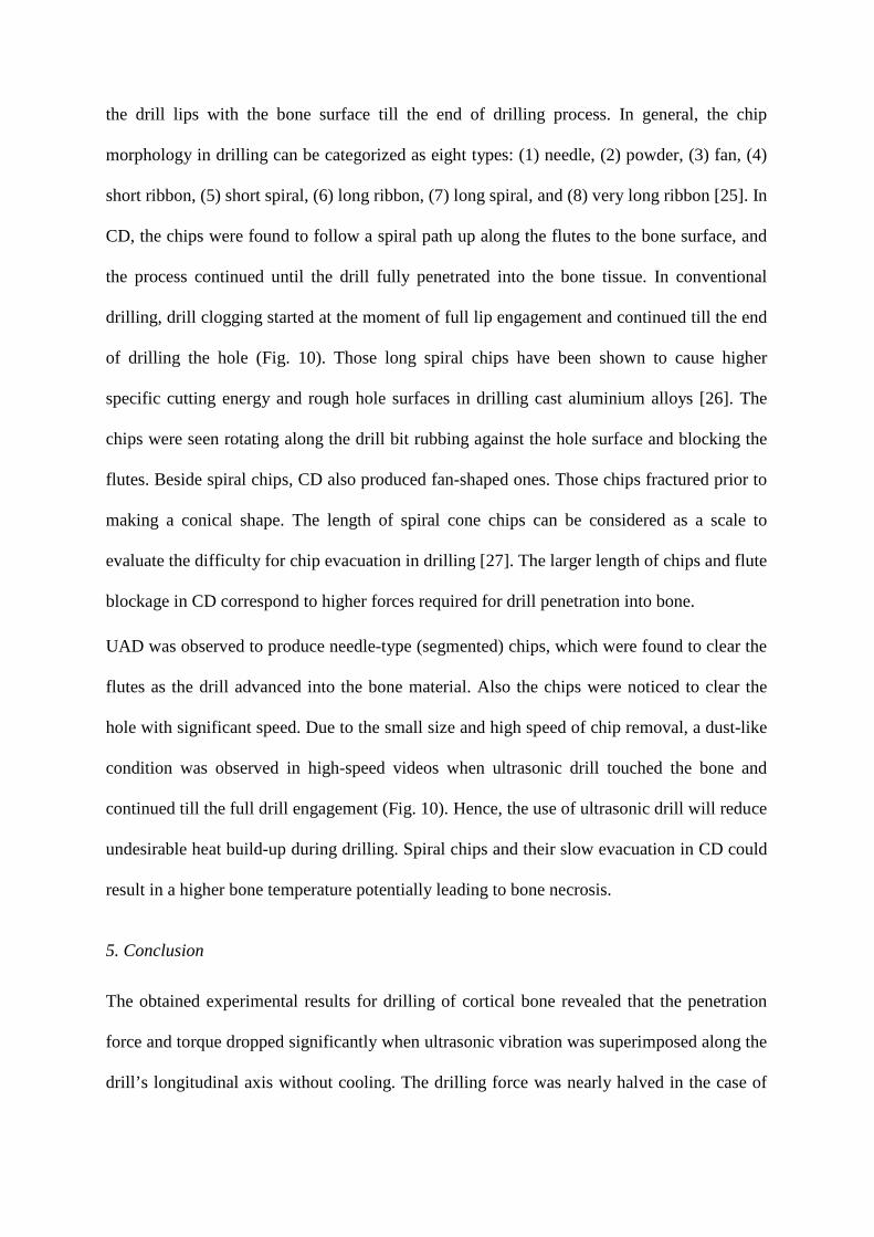
The reaction force and torque generated during CD and UAD were studied using the
experimental arrangement shown in Fig. 3. The experiments were carried out on a three-axis
CNC milling machine (Wadkin Machine Tools, UK) with an ultrasonic transducer gripped in
its chuck. The maximum spindle speed of the machine is 10,000 rpm and the feed rate 10
m/min. A two-component dynamometer (Kistler type 9271A), which can measure the thrust
force and torque, was used. The force and torque signals generated by the Kistler
dynamometer were conditioned using Kistler charge amplifiers, captured using a digital
oscilloscope and transferred to a PC for subsequent processing. The Picoscope series 2000
oscilloscope with a maximum frequency of 10 MHz was used to acquire the data for force
and torque in a digital format.
2.3. Experimental procedure
All the experiments were performed at room temperature without cooling (apart of a light
spray of water near the drilling site to avoid dryness of the specimen) as in real orthopaedic
surgery; the drilling direction was perpendicular to the bone’s longitudinal axis. The metal
plate with the glued sample was clamped on the dynamometer platform to provide rigidity
(see Fig. 3a). Prior to the experiments, the dynamometer was calibrated and found to be
accurate in responses to both forms of loading (longitudinal and torsional). In the
experimental study, a drill bit was feed down into the workpiece upon application of a thrust
force along the drill axis. At the first stage of experiments, the drilling force and torque were
measured under conventional conditions (no ultrasonic excitation) for a set of drilling
parameters. Then, the drilling tests were performed with the ultrasonic transducer switched
on for the same cutting parameters used previously in CD (these parameters are provided in
Table 1). The amount of thrust force required to drill a hole in a workpiece is related to the
total energy per unit volume required to cut the material and diameter of the drill bit [7].
3. Mechanism of ultrasonically-assisted cutting
In UAC the displacement x of vibrating tool is given by
ftatax πω 2sinsin ==
where a , f and ω are, respectively, the amplitude, frequency and angular velocity of the
tool. Thus, the tool vibration speed is costv x a tω ω= = . In UAC, the tool-work piece
contact is intermittent, i.e. the tool remains in a contact with a bone onlyfor a certain part of
vibration cycle. The vibrational cutting condition is satisfied if the tool speed is more than the
work piece cutting velocity, resulting in a separation of the tool from the workpiece in each
cycle. The cutting force is produced only in the tool-workpiece contact period of the
vibration cycle. A detailed description of models of ultrasonically-assisted machining
processes can be found in [22].
4. Results and discussion
Typical force-time graphs obtained for both drilling techniques are shown in Fig. 4. After the
initial engagement, the force gradually increased with time and attained a plateau when the
drill lip was fully engaged with the bone. Small oscillations recorded at peak values are due
to high sensitivity of the measurement system and vibrations in the drilling equipment. The
force suddenly vanished when the drill penetrated entire thickness of cortical bone (approx. 9
mm).

4.1. Effect of drilling speed on force
The effect of drilling speed on the thrust force was measured for CD and UAD, and the
obtained results are presented in Fig. 5 (here and below, all the data points in the graphs are
the mean of five tests). UAD resulted in a significant decrease in thrust forces for the range
of speeds and feed rates used. The thrust force decreased with the drilling speed for both
drilling techniques (CD and UAD) for magnitudes above 1800 rpm. The decrease of the
drilling force can be explained by the reduction of the mean friction coefficient at the drill-
bone interface at higher cutting speeds. This may also be due to the change in the chip
formation mechanism at higher speeds that can affect the drilling thrust force. The average
value of the force measured was 66 N and 48 N for 600 rpm and 3000 rpm, respectively, in
CD and was 36 N and 21 N in UAD for the same drilling speeds and feed rate. A decrease in
force by 27% was observed in CD when the drilling speed was varied from 600 rpm to 3000
rpm. With the vibrating drill, the force dropped by 45% for 600 rpm and 55% for 3000 rpm
compared to conventional technique. Our results for CD are consistent with those obtained in
[23], where the thrust force was shown to drop exponentially with speed in drilling bovine
cortical bone (for a 3.2 mm drill). In that study the thrust force dropped from 48 N at 400
rpm to 23 N at 2000 rpm.
4.2. Effect of feed rate on force
The influence of feed rate on the drilling thrust force was also studied. The force declined by
a significant magnitude with the decreasing feed rate in CD as shown in Fig. 6. Interestingly,
but not surprisingly, the force level was significantly less affected in the case of the
ultrasonic vibrations for the range of feed rates used. The reason was the large difference
between the actual velocity of the tip of the drill in UAD due to high-frequency vibration and
the feed rate. Here, as above, UAD consistently demonstrated a lower level of trust force.

4.3. Effect of drilling speed on torque
The effect of drilling speed on torque was also examined. In CD, the torque diminished
significantly as the speed was changed from 600 rpm to 1800 rpm as shown in Fig. 7; the
effect was negligible for speeds above 1800 rpm. In UAD, the drop was linear up to the
drilling speed of 2400 rpm and was not affected by the speed above it. The average drop in
the torque was about 30% in CD and UAD for the range of drilling speed used. The
magnitude and behaviour of our results for drilling torque against drilling speed in CD was
consistent with those reported in [23]. There it was shown that in tests with a 3.2 mm drill,
there was an exponential falling-off of the cutting torque from 14.5 N mm at 400 rev/min to
an asymptote of 10 N mm at 2000 rev/min.
4.4. Effect of ultrasonics on force and torque
The influence of parameters of ultrasonic vibration on drilling thrust force and torque was
studied next. Comparing Fig. 8 and Fig. 9 with the experimental results discussed above,
several trends can be deduced. Firstly, the drilling reaction force and torques developed
during UAD were lower than those generated during CD throughout the frequency range
investigated. With regard to the effect of vibration frequency, it was found that the thrust
force decreased by 57% when the frequency was increased from 10 kHz to 30 kHz (Fig. 8).
The corresponding drop in torque was 28%. The decrease in drilling force with an increase in
ultrasonic frequency was due to the decrease in contact ratio between the drill and the bone.
It was expected that the decrease in that ratio reduced the mean friction coefficient at the
drill-bone interface.
The force dropped by 46% when the ultrasonic amplitude was increased from 5 µm to 15 µm
and was unaffected by a further increase (Fig. 9). The torque diminished slightly (by 14%)
when the amplitude was changed from 5 µm to 10 µm and remained unchanged under further
increases in the amplitude. The drilling force was shown to drop linearly with vibration
amplitude in drilling ceramics using a diamond core drill [24]. Here, it is important to
mention that the largest change in the thrust force and torque was for the maximum drilling
speed of 3000 rpm. Hence, different optimum values for vibration frequency and amplitude
can exist for higher drilling speeds. The advantage of using UAD is the lower level of torque
applied at all times that will prevent the drill from stalling.
4.5. Chip formation in drilling
A study of chip formation in both used drilling techniques can elucidate the reasons for
differences in drilling forces. A mechanism of the chip formation process in CD and UAD
was visualised using high-speed filming that provided direct observation of the drill-bone
interaction zone. The FASTCAM digital video recorder (Photron DVR, Photron Limited,
Japan) was utilized for filming of the chip separation process. The videos were recorded at
500 frames per second with resolution of 640×480 pixels for the duration of approximately
10 seconds. A macro zoom (18–108 mm) lens was used to zoom into the drilling location.
High-speed filming is capable of recording images of events occurring for short time periods
and thus gives an opportunity to study the chip formation of a fast process such as drilling.
One of the major limitations of high-speed filming is that recording at high frame rates
requires the provision of very intense lighting and proper focus on the area of interest. To
illuminate the filming area, two high-intensity lighting sets (quartz flood lighting) of 700 W
were used. Due to the light reflection from the tool and specimen, it was difficult to observe
clear images of the cutting process on the screen. To eliminate that problem, the drill bit (tip
and flutes) were blacked with a marker resulting in a clearer picture of the chip formation in
the cutting zone. The chip formation was observed from the moment of initial engagement of
the drill lips with the bone surface till the end of drilling process. In general, the chip
morphology in drilling can be categorized as eight types: (1) needle, (2) powder, (3) fan, (4)
short ribbon, (5) short spiral, (6) long ribbon, (7) long spiral, and (8) very long ribbon [25]. In
CD, the chips were found to follow a spiral path up along the flutes to the bone surface, and
the process continued until the drill fully penetrated into the bone tissue. In conventional
drilling, drill clogging started at the moment of full lip engagement and continued till the end
of drilling the hole (Fig. 10). Those long spiral chips have been shown to cause higher
specific cutting energy and rough hole surfaces in drilling cast aluminium alloys [26]. The
chips were seen rotating along the drill bit rubbing against the hole surface and blocking the
flutes. Beside spiral chips, CD also produced fan-shaped ones. Those chips fractured prior to
making a conical shape. The length of spiral cone chips can be considered as a scale to
evaluate the difficulty for chip evacuation in drilling [27]. The larger length of chips and flute
blockage in CD correspond to higher forces required for drill penetration into bone.
UAD was observed to produce needle-type (segmented) chips, which were found to clear the
flutes as the drill advanced into the bone material. Also the chips were noticed to clear the
hole with significant speed. Due to the small size and high speed of chip removal, a dust-like
condition was observed in high-speed videos when ultrasonic drill touched the bone and
continued till the full drill engagement (Fig. 10). Hence, the use of ultrasonic drill will reduce
undesirable heat build-up during drilling. Spiral chips and their slow evacuation in CD could
result in a higher bone temperature potentially leading to bone necrosis.
5. Conclusion
The obtained experimental results for drilling of cortical bone revealed that the penetration
force and torque dropped significantly when ultrasonic vibration was superimposed along the
drill’s longitudinal axis without cooling. The drilling force was nearly halved in the case of

vibration for the range of drilling speeds used. The lower drilling torque in ultrasonically-
assisted drilling reduces the chance of drill skidding and breakage. In addition, the risk of
damage caused by the drilling torque may also be minimized. Another advantage of UAD
compared to conventional drilling is improved chip removal from the drilling site. The
intermittent contact between the drill and bone in UAD is expected to produce lower heat
since it diminishes chip rubbing against the drill hole leading to reduced friction. The
obtained decrease in the force will allow surgeons to penetrate the tool with lower effort and
will have a better control over the cutting process. Further research is also needed to evaluate
the integrity of the drilled hole’s surface produced in both types of drilling techniques in
order to ensure that interfacial strength is not affected.
Conflicts of interest None Acknowledgements The authors wish to thank Dr Alan Meadows (Loughborough University, UK) for his support with the experiments. References [1] Harrysso OL, Hosni YA, Nayfeh JF. Custom-designed orthopaedic implants evaluated using finite element analysis of patient-specific computed tomography data: femoral- component case study. BMC Musculoskelet Disord 2007;8:91. [2] Bachus KN, Rondina MT, Hutchinson DT. The effects of drilling force on cortical
temperatures and their duration: an in-vitro study. Med Eng Phys 2000;22(10):685–91.
[3] Brisman DL. The effect of speed, pressure, and time on bone temperature during the drilling of implant sites. Int J Oral Maxillofac impl 1996;11:35–7. [4] Karmani S, Lam F. The design and function of surgical drills and K-wires. Current Orthopaedics 2004;18:484–90.
[5] Natali C, Ingle P, Dowell J. Ortopaedic bone drills-can they be improved? J Bone Joint Surg Br 1996;78-B:352–57.

[6] Brett PN, Baker DA, Griffiths MV, Reyes L. An automatic technique for controlling
the penetration of a micro-drilling through flexible bone tissue. Seminar on Minimally Invasive Surgery, IMechE, HQ, London, 28 February (1995).
[7] Allotta B, Belmonte F, Bosio L, Dario P. Study on a mechatronic tool for drilling in
the osteosynthesis of long bones: tool/bone interaction, modeling and experiments. Mechatronics 1996;6(4):447–59.
[8] Lee W, Shih CL, Lee ST. Force control and breakthrough detection of a bone-drilling
system. IEEE/ASME Transactions on Mechatronics 2004;9(1). [9] Saha S, Pal S, Albright JA. Surgical drilling: design and performance of an improved drill. J Biomech Eng 1982;104:245–52. [10] Pal S, Saha S. Analysis and performance of a new improved surgical drill. Advances
in Bioengineering. ASME 1981;51–53. [11] Wiggins KL, Malkin S. Drilling of bone. J Biomech 1976;9:553–59. [12] Yilbas BS, Z. Yilbas Z, Sami M. Thermal processes taking place in the bone during
CO2 laser irradiation. Opt Laser Technol 1996:28(7):513–19. [13] Chen IH, Saha S. Thermal analysis of the bone surface induced by laser radiation.
Ann Biomed Eng 1987;15:457–66. [14] Mitrofanov AV, Babitsky VI, Silberschmidt VV. Thermomechanical finite element simulations of ultrasonically assisted turning. Comput Mater Sci 2005;32:463–71. [15] Li ZC, Jiao Y, Deines TW, Pei ZJ, Treadwell C. Rotary ultrasonic machining of
ceramic matrix composites: feasibility study and designed experiments. Int J Mach Tool Manufact 2005;45:1402–11.
[16] Lucas M, MacBeath A, McCulloch E, Cardoni A. A finite element model for
ultrasonic cutting. Ultrasonics 2006;44:503–9. [17] Khambay BS, Walmsley AD. Investigations into the use of an ultrasonic chisel to cut bone. Part 2: Cutting ability. J Dent 2000;28:39–44. [18] Matthews LS, Hirsch CH. Temperatures measured in human cortical bone when
drilling. J Bone Joint Surg 1972;54A:297–308. [19] Jacobs CH, Pope MH, Berry JT, Hoagland FT. A study of the bone machining
process - Drilling. J Biomech 1976;9(5):343–49. [20] Vashishth D. Rising crack-growth-resistance behaviour in cortical bone: implications
for toughness measurements. Short communication, J Biomech 2004;37:943–46.

[21] Mitrofanov AV. Modelling the ultrasonically assisted turning of high-strength alloys. PhD Dissertation, Wolfson School of Mechanical and Manufacturing Engineering, Loughborough University, 2004. [22] Astashev VK, Babitsky VI. Ultrasonic Processes and Machines, Dynamics, Control
and Applications. Springer Berlin Heidelberg; 2007. [23] Hillery MT, Shuaib I. Temperature effects in the drilling of human and bovine bone. J
Mater Proc Technol 1999;92–93:302–8. [24] Ishikawa K, Suwabe H, Nishide T, Uneda M. A study on combined vibration drilling
by ultrasonic and low-frequency vibrations for hard and brittle materials. Prec Eng 1998;22:196–205.
[25] Bakkal M, Shih AJ, McSpadden SB, Liu CT, Scattergood RO. Light emission, chip morphology, and burr formation in drilling the bulk metallic glass. Int J Mach Tool Manufact 2005;45:741–52. [26] Batzer SA, Haan DM, Rao PD, Olson WW, Sutherland JW. Chip morphology and hole surface texture in the drilling of cast Aluminum alloys. J Mater Proc Technol 1 998;79:72–8.
[27] Li R, Hegde P, Shih AJ. High-throughput drilling of titanium alloys. Int J Mach Tool Manufact 2007;47:63–74.

Figures Captions Fig. 1. (a) Fresh bovine femur bone; (b) sample cut from mid diaphysis; (c) specimen for
drilling
Fig. 2. Components of ultrasonically-assisted cutting system Fig. 3. (a) Experimental arrangement for measurement of thrust force and torque in
drilling; (b) schematic of ultrasonic device for drilling
Fig. 4. Evolution of force, measured with dynamometer, in CD and UAD. Drilling speed N
=1800 rpm; fr = 40 mm/min (I – drill engagement stage; II – drilling; III – drill exit)
Fig. 5. Influence of drilling speed on thrust force in CD and UAD (fr = 40 mm/min,
frequency f = 20 kHz, amplitude a =10 micrometers)
Fig. 6. Influence of feed rate on thrust force in CD and UAD. Drilling speed N = 1800 rpm,
frequency f = 20 kHz, amplitude a = 10 micrometers
Fig. 7. Influence of drilling speed on torque in CD and UAD. Frequency f = 20 kHz,
amplitude a =10 micrometers, fr = 40 mm/min
Fig. 8. Variation of thrust force and torque with vibration frequency in UAD. Drilling speed
N =1800 rpm, fr = 40 mm/min, amplitude a =10 micrometers
Fig. 9. Variation of thrust force and torque with vibration amplitude in UAD. N =1800 rpm,
fr = 40 mm/min, frequency f = 20 kHz
Fig. 10. Images obtained with high-speed video system showing chip formation in
drilling fresh bone with both drilling modes. First row: CD, second row: UAD. Left

column – initial engagement of drill lips; middle column – half-lip engagement; right column
– full lip engagement

Fig. 1

Fig. 2
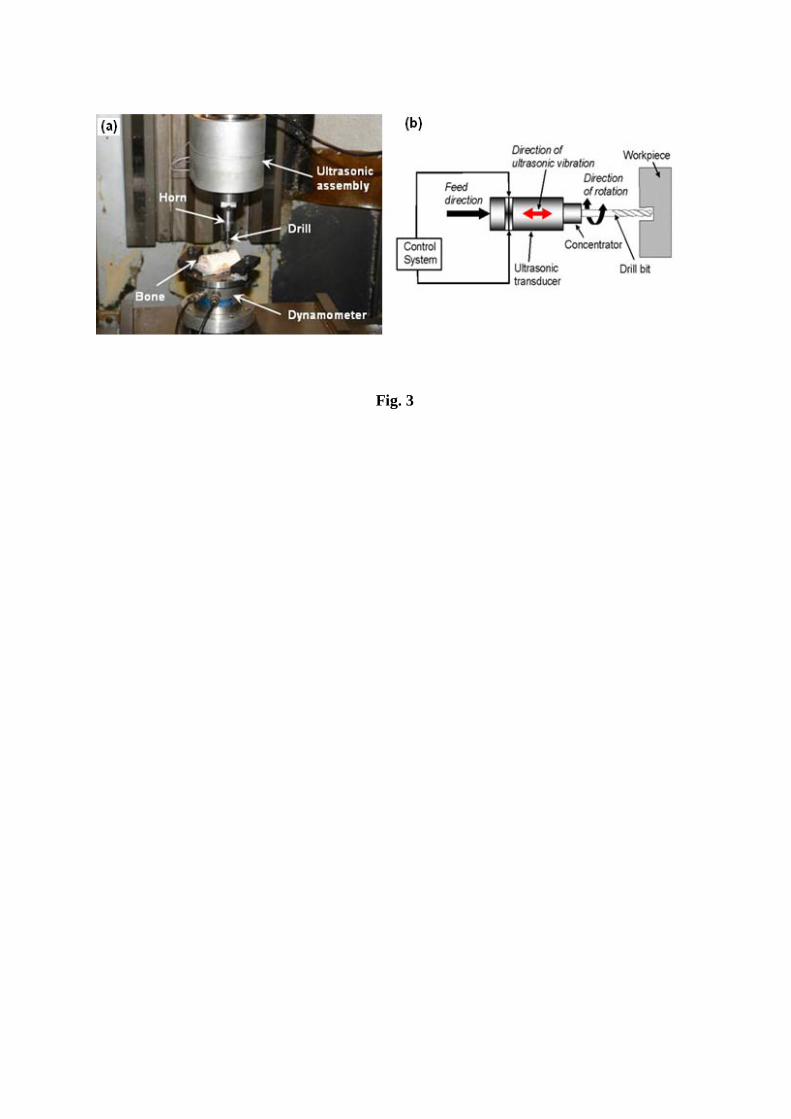
Fig. 3

Fig. 4
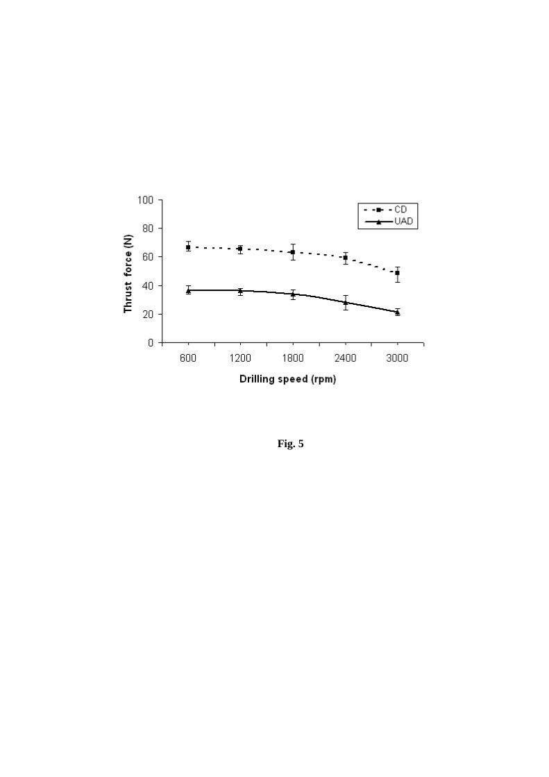
Fig. 5

Fig. 6

Fig. 7
Fig. 8

Fig. 9

Fig. 10
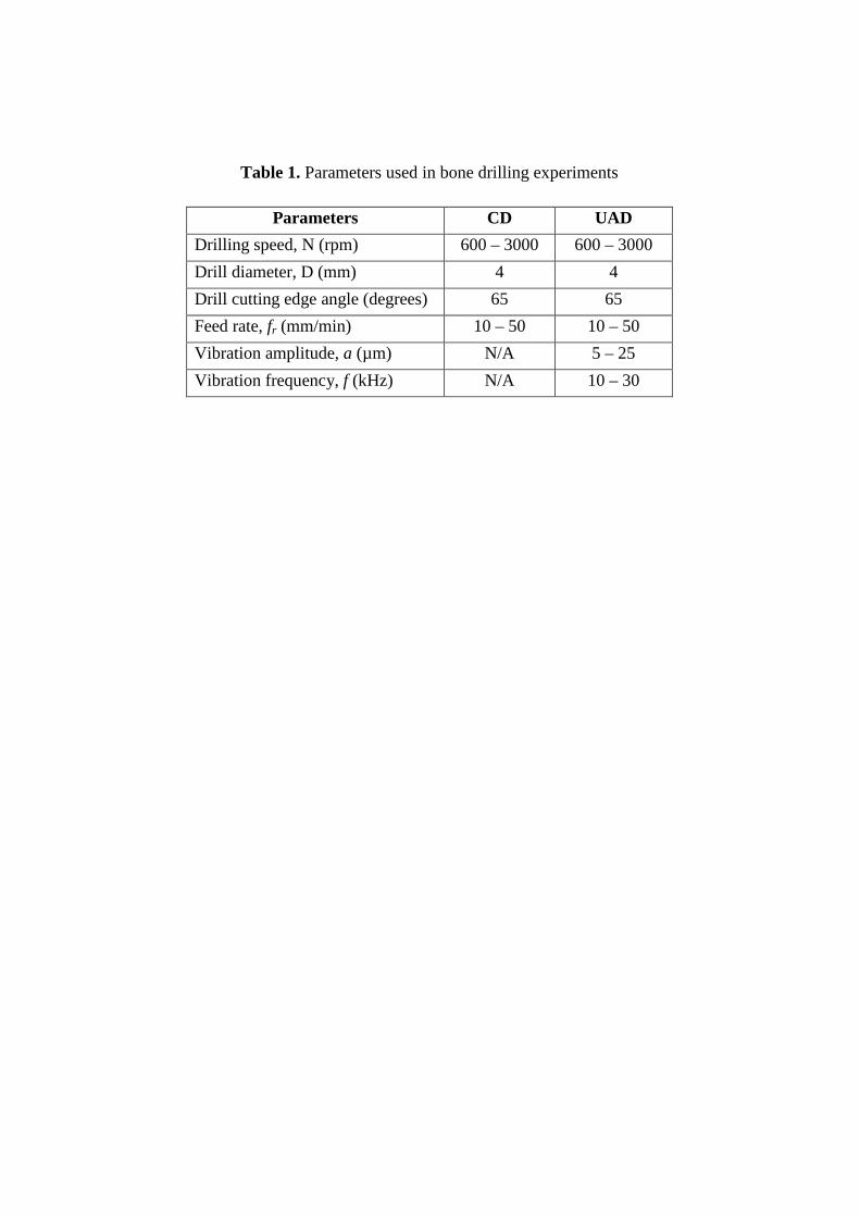
Table 1. Parameters used in bone drilling experiments
Parameters CD UAD
Drilling speed, N (rpm) 600 – 3000 600 – 3000 Drill diameter, D (mm) 4 4 Drill cutting edge angle (degrees) 65 65 Feed rate, fr (mm/min) 10 – 50 10 – 50 Vibration amplitude, a (µm) N/A 5 – 25 Vibration frequency, f (kHz) N/A 10 – 30