experimental investigation of effect of printing
TRANSCRIPT

Experimental investigation of effect of printing parameters on impactstrength of the bio-inspired 3D printed specimen
MAHESH NAIK and DINESHSINGH G THAKUR*
Department of Mechanical Engineering, DIAT (DU), Ministry of Defence, Pune, Maharashtra 411 025, India
e-mail: [email protected]; [email protected]
MS received 27 August 2020; revised 15 March 2021; accepted 24 June 2021
Abstract. Additive Manufacturing (AM) has the ability to fabricate complex structures with bio-mimicry
features. Fused Deposition Modeling (FDM), which is AM technique, has the capability of creating complex
geometry parts in a short time. The mechanical properties of FDM build parts can be improved by selecting the
proper printing parameters. In the present study, the effect of printing parameters viz. printing orientation (flat
and on-edge) and infill density (20%, 35%, 50%, 65%, 80% and 100%) on the impact strength of bio-inspired 3D
printed specimen has been studied. The specimens with multi-infill pattern were inspired by bio-inspired
structure like a turtle shell. The multi-infill pattern specimen includes triangular, honeycomb and grid infill
patterns. Based on this multi-infill pattern, impact specimens were fabricated and tested. Impact strength and
impact strength/weight ratio of specimens in flat and on-edge orientation are measured and evaluated. The result
shows that the impact strength and impact strength/weight ratio of multi-infill pattern specimens printed in flat
orientation is less compared to specimens printed in on-edge orientation. The multi-infill pattern specimen with
20% infill density printed in on-edge orientation has the highest impact strength and impact strength/weight ratio
as compared to other specimens. Further, high magnification fracture surface analysis is performed to aid in the
characterisation of specimen failures.
Keywords. 3D-printing; FDM; PLA; bio-inspired specimen; impact strength.
1. Introduction
In 1986, Charles Hull first described the Additive Manu-
facturing (AM) technology, also known as 3D printing [1].
In recent decades, there has been a rise in many AM pro-
cesses that have brought benefits to engineering design and
manufacturing processes. 3D printing has the capability to
fabricate complex parts with high resolution and rapid
fabrication. It has the ability to assign material properties at
the sub-millimetre scale, inspiring multi-material, func-
tionally graded designs, thus making it an attractive option
for composite material development [2]. Additionally, 3D
printing simplifies the mimicking of bio-inspired structures
like honeycomb and molluscan shell [3–5]. The 3D printing
technique involves processes such as Fused Deposition
Modelling (FDM), Stereolithography (SLA), Laminated
Object Manufacturing (LOM), Binder Jetting (BJ), Selec-
tive Laser Melting (SLM) and Selective Laser Sintering
(SLS). Among these AM techniques, FDM is the most
widely used method due to its reliability, low cost and
minimised waste.
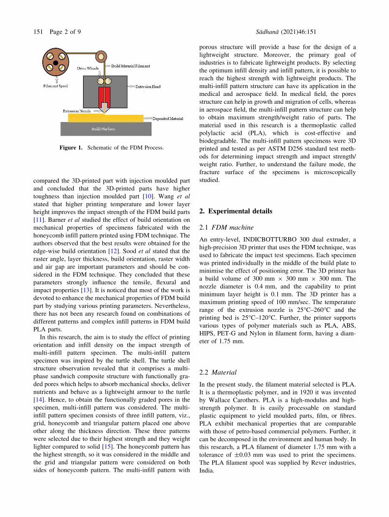
In the FDM process, a polymer in filament form is fed
into extrusion head. In extrusion head, the filament is
heated and the molten filament is extruded from the nozzle
and deposited on the heated plate to form the part layer-by-
layer as defined by the CAD data [6]. The schematic of the
FDM process is shown in figure 1. FDM printed parts have
their application in the field of aerospace, automobile,
biomedical and consumer part industries. However, the
poor mechanical properties of the FDM 3D printed part
restrict its application. By selecting proper printing
parameters, the mechanical properties of the FDM build
parts can be enhanced.
Recently, some work has been done by researchers to
improve the mechanical properties of the FDM build parts.
Sin et al used PLA with Blendex 338 as an impact modifier.
They observed that PLA, when blended with Blendex 338
showed increased impact strength [7]. Afrifah et al com-
bined PLA with ethylene/acrylate copolymer and found that
the combinations showed a decrease in tensile strength and
modulus with the increasing impact strength [8]. Lee et alstudied the influence of process parameters such as air gap,
layer thickness, raster angle and raster width in order to
achieve optimum elastic performance of a compliant ABS
prototype using the Taguchi method. They found that the
optimum level of parameters viz., air gap, raster angle,
raster width and layer thickness were double-wide, 30�/60�,0.980 mm and 0.178 mm, respectively [9]. Song et al*For correspondence
Sådhanå (2021) 46:151 � Indian Academy of Sciences
https://doi.org/10.1007/s12046-021-01671-8Sadhana(0123456789().,-volV)FT3](0123456789().,-volV)
compared the 3D-printed part with injection moulded part
and concluded that the 3D-printed parts have higher
toughness than injection moulded part [10]. Wang et alstated that higher printing temperature and lower layer
height improves the impact strength of the FDM build parts
[11]. Barner et al studied the effect of build orientation on
mechanical properties of specimens fabricated with the
honeycomb infill pattern printed using FDM technique. The
authors observed that the best results were obtained for the
edge-wise build orientation [12]. Sood et al stated that the
raster angle, layer thickness, build orientation, raster width
and air gap are important parameters and should be con-
sidered in the FDM technique. They concluded that these
parameters strongly influence the tensile, flexural and
impact properties [13]. It is noticed that most of the work is
devoted to enhance the mechanical properties of FDM build
part by studying various printing parameters. Nevertheless,
there has not been any research found on combinations of
different patterns and complex infill patterns in FDM build
PLA parts.
In this research, the aim is to study the effect of printing
orientation and infill density on the impact strength of
multi-infill pattern specimen. The multi-infill pattern
specimen was inspired by the turtle shell. The turtle shell
structure observation revealed that it comprises a multi-
phase sandwich composite structure with functionally gra-
ded pores which helps to absorb mechanical shocks, deliver
nutrients and behave as a lightweight armour to the turtle
[14]. Hence, to obtain the functionally graded pores in the
specimen, multi-infill pattern was considered. The multi-
infill pattern specimen consists of three infill pattern, viz.,
grid, honeycomb and triangular pattern placed one above
other along the thickness direction. These three patterns
were selected due to their highest strength and they weight
lighter compared to solid [15]. The honeycomb pattern has
the highest strength, so it was considered in the middle and
the grid and triangular pattern were considered on both
sides of honeycomb pattern. The multi-infill pattern with
porous structure will provide a base for the design of a
lightweight structure. Moreover, the primary goal of
industries is to fabricate lightweight products. By selecting
the optimum infill density and infill pattern, it is possible to
reach the highest strength with lightweight products. The
multi-infill pattern structure can have its application in the
medical and aerospace field. In medical field, the pores
structure can help in growth and migration of cells, whereas
in aerospace field, the multi-infill pattern structure can help
to obtain maximum strength/weight ratio of parts. The
material used in this research is a thermoplastic called
polylactic acid (PLA), which is cost-effective and
biodegradable. The multi-infill pattern specimens were 3D
printed and tested as per ASTM D256 standard test meth-
ods for determining impact strength and impact strength/
weight ratio. Further, to understand the failure mode, the
fracture surface of the specimens is microscopically
studied.
2. Experimental details
2.1 FDM machine
An entry-level, INDICBOTTURBO 300 dual extruder, a
high-precision 3D printer that uses the FDM technique, was
used to fabricate the impact test specimens. Each specimen
was printed individually in the middle of the build plate to
minimise the effect of positioning error. The 3D printer has
a build volume of 300 mm 9 300 mm 9 300 mm. The
nozzle diameter is 0.4 mm, and the capability to print
minimum layer height is 0.1 mm. The 3D printer has a
maximum printing speed of 100 mm/sec. The temperature
range of the extrusion nozzle is 25�C–260�C and the
printing bed is 25�C–120�C. Further, the printer supports
various types of polymer materials such as PLA, ABS,
HIPS, PET-G and Nylon in filament form, having a diam-
eter of 1.75 mm.
2.2 Material
In the present study, the filament material selected is PLA.
It is a thermoplastic polymer, and in 1920 it was invented
by Wallace Carothers. PLA is a high-modulus and high-
strength polymer. It is easily processable on standard
plastic equipment to yield moulded parts, film, or fibres.
PLA exhibit mechanical properties that are comparable
with those of petro-based commercial polymers. Further, it
can be decomposed in the environment and human body. In
this research, a PLA filament of diameter 1.75 mm with a
tolerance of ±0.03 mm was used to print the specimens.
The PLA filament spool was supplied by Rever industries,
India.
Figure 1. Schematic of the FDM Process.
151 Page 2 of 9 Sådhanå (2021) 46:151

2.3 Printing parameters
The impact strength of the 3D-printed part is primarily
dependent on the selection of the printing parameters.
Hence, in the present study, the two key printing parame-
ters: printing orientation (Flat and On-edge) as shown in
figure 2 and percent infill density (20%, 35%, 50%, 65%,
80% and 100%) as shown in figure 3 are selected for the
investigation of impact strength of multi-infill pattern
specimen. Table 1 shows the fixed printing parameters that
are considered during the printing of multi-infill pattern
impact specimens.
2.4 Fabrication of specimen
The 3D CAD model of the test specimen was created in
Solidworks 2018 and exported as an STL file, and
according to ASTM D256 (ASTM 2010) [16], the geometry
was set as shown in figure 4. The STL file is then uploaded
into the slicing software, where it sliced the STL file to
create tool pathways and export the instructions as a
G-Code file. Then the G-Code file is submitted to an
INDICBOTTURBO 300 dual extruder 3D printer to print
the multi-infill pattern impact specimens. The multi-infill
pattern specimens were created using the multi-process
function of the slicer software. In the case of on-edge ori-
entation, it consists of four sections, i.e. 100% infill density,
triangular pattern, honeycomb pattern and grid pattern
sections from top to bottom respectively along width
direction and in case of flat orientation, it consists of three
sections, i.e. triangular pattern, honeycomb pattern and grid
pattern sections from top to bottom respectively along
thickness direction as shown in figure 5. The 3D sections of
multi-infill pattern specimen for flat orientation with dif-
ferent infill pattern distribution is shown in figure 6. Also,
figure 7 shows the 3D printed specimens for the izod impact
test.
2.5 Izod impact testing of 3D printed specimen
The izod impact specimens were tested on an IT 503 izod
impact tester. The tester features heavy-duty construction
with a solid steel base and thick-walled column. It consists
of the compound pendulum, which has been aerodynami-
cally designed to provide maximum rigidity and virtually
eliminates windage losses. Low friction bearings are fitted
to reduce mechanical losses. The tester incorporates a
microprocessor system, which automatically calculates and
displays the impact energy absorbed by a specimen. Before
testing, a simple calibration of the machine is done, which
automatically calculates the windage and friction losses and
subtracts from the final reading. The IT 503 impact tester
includes a standard pendulum capable of delivering nomi-
nal energy of 2.82 Joules at a 610 mm drop height, and by
adding optional weights, the pendulum capacity can be
increased up to 25 Joules.
The Izod impact testing is carried out as per ASTM D256
standards. Five impact test specimens were printed and
tested at each printing orientation and infill density. In this
test, the notched specimen was fixed between the vices at
one end of the specimen, which resulted in the specimen
being held in a cantilever position (figure 8 for the equip-
ment set-up). Clamping was done only finger-tight to pro-
vide a secure base for the specimen. The pendulum carrying
the Izod striking bit strikes the specimen on the unsecured
end. Before starting the test, the arm of the pendulum is set
to 0� and then it is released. During the Izod impact test, the
specimen is subjected to a rapid and intense blow from a
pendulum that hits the specimen. The energy absorbed by
the specimen until failure is known as the impact energy.
Impact strength is calculated by taking the ratio of impact
energy to the thickness of the specimen.
2.6 Morphology
Scanning Electron Microscopy (SEM) analysis was
employed to characterise the failure of the specimens. The
morphology of fracture surfaces of the 3D printed PLA
specimens was observed using SEM (SIGMA, Carl Zeiss
Field Emission Scanning Electron Microscopy). The frac-
ture surface of the specimens was coated with gold before
SEM examinations.
3. Results and discussion
The multi-infill pattern impact specimens were tested by
considering two printing orientation and six percent infill
density. The printing time of specimens, weight of speci-
mens and values obtained from the impact tests such as
impact strength and impact strength/weight ratio were listed
in table 2. The combination of each printing orientation and
percent infill density showed different results and different
fracture styles.
3.1 Printing time and weight of specimen
Figure 9 shows the printing time vs infill density of multi-
infill pattern specimens printed with flat and on-edge build
orientation. The x-axis represents infill density and the
y-axis represents printing time. Figure 10 shows the weight
vs infill density of multi-infill pattern specimens printed
with flat and on-edge build orientation. The x-axis repre-
sents infill density, and the y-axis represents weight. From
figures 9 and 10, it is observed that the printing time and
weight increases as the percent infill density increases for
specimens in both orientations. As the percent infill density
increases, the volume occupied by polymer material
Sådhanå (2021) 46:151 Page 3 of 9 151

increases which results in more deposition of material.
Also, the printing time and weight are more for specimens
printed in on-edge orientation compared to specimens
printed in flat orientation. In the case of on-edge orienta-
tion, the layer-by-layer printing is done along the width
direction, whereas in a flat orientation, the layer-by-layer
printing is done along the thickness direction. This results
in more volume occupied by the counters in on-edge ori-
entation as compared to flat orientation. Due to this, the
printing time and weight of specimens printed in on-edge
orientation are more than flat orientation.
Figure 3. 3D views of izod impact specimens for flat orientation with different percent infill density (a) 20%, (b) 35%, (c) 50%,
(d) 65%, (e) 80% and (f) 100%.
Figure 2. 3D views of printing orientations of izod impact specimen.
Table 1. Fixed printing parameters.
Sl. no. Printing parameters Value
1. Nozzle temperature (�C) 200
2. Bed temperature (�C) 60
3. Printing speed (mm/sec) 40
4. Layer Height (mm) 0.15
5. Number of contours 2
6. Nozzle size (mm) 0.4
Figure 4. 2D geometry of izod impact test specimen as per ASTM D256.
151 Page 4 of 9 Sådhanå (2021) 46:151

3.2 Impact strength and impact strength/weightratio
Figure 11 depicted the effect of build orientations and
percentage infill density on impact strength of the FDM
build multi-infill pattern specimens. From figure 11, it is
observed that multi-infill pattern specimen printed in on-
edge orientation has higher impact strength compared to
that of flat orientation. In flat orientation specimens, less
raster meeting junction of infill patterns and fewer counter
layers come in contact with the impact load as the build
direction of the specimen is along the thickness direction
whereas, for on-edge orientation specimens, more raster
meeting junction of infill patterns and more counter layers
Figure 8. Experimental set-up for the izod impact test.
Figure 7. 3D printed izod impact test specimens.
Figure 5. Sections of multi-infill pattern specimen for two orientations.
Figure 6. 3D sections of flat orientated multi-infill pattern specimen with infill pattern distribution (50% infill density specimen).
Sådhanå (2021) 46:151 Page 5 of 9 151

come in contact with the impact load as the build direction
of the specimen is along the width direction. Also, the
specimens with different infill density in both orientations
show different impact strength. These difference in impact
strength for multi-infill pattern specimens can be explained
by fracture styles associated with them. Figure 12 shows
the SEM images of fractured surfaces of multi-infill pattern
specimens with different infill density in both orientations.
In figure 12, the red, blue and yellow box represents the
fracture surface of triangular, honeycomb and grid infill
pattern respectively of multi-infill pattern specimen.
In flat orientation, the multi-infill pattern specimen with
50% infill density has the highest impact strength of
95.57 J/m, and the specimen with 20% infill density has the
lowest impact strength of 80.29 J/m. The specimen with
35%, 65%, and 80% infill density has nearly the same
impact strength of 85.19 J/m, 86.08 J/m and 85.63 J/m,
respectively. The specimen with 100% infill density has an
impact strength of 92.09 J/m. For flat orientation
Table 2. Summarised izod impact testing results.
Printing Orientation Infill Density (%) Print Time (min) Weight (g) Impact Strength (J/m) Impact Strength/Weight ratio (J/mg)
Flat 20 11 1.05 80.29 76.47
35 13 1.34 85.19 63.42
50 15 1.63 95.57 58.63
65 17 1.82 86.08 47.21
80 19 2.09 85.63 40.97
100 21 2.35 92.09 39.13
On-edge 20 22 2.16 212.74 98.64
35 23 2.26 171.90 76.18
50 24 2.31 159.68 69.03
65 25 2.41 176.61 73.38
80 26 2.46 198.78 80.80
100 27 2.55 190.58 74.64
20 35 50 65 80 1000.0
0.5
1.0
1.5
2.0
2.5
3.0
Wei
ght (
g)
Infill Density (%)
Flat Onedge
Figure 10. Comparison of the weight of the impact specimens.
20 35 50 65 80 1000
50
100
150
200
250
Impa
ct S
tren
gth
(J/m
)
Infill Density (%)
FlatOnedge
Figure 11. Comparison of impact strength of the specimens.
20 35 50 65 80 1000
5
10
15
20
25
30
Prin
ting
Tim
e (m
in)
Infill Density (%)
FlatOnedge
Figure 9. Comparison of the printing time of the impact
specimens.
151 Page 6 of 9 Sådhanå (2021) 46:151

specimens, it is observed from figures 12(a-f) that the
fracture in the specimen with 20% infill density is due to
failure at raster meeting junction of triangular and honey-
comb pattern and trans-raster failure of the grid pattern.
Due to the availability of less material to resist load, 20%
infill density specimen shows less impact strength. For the
35% infill density specimen, the fracture is due to failure at
raster meeting junction of all three infill pattern. For 50%
infill density specimen, the fracture is due to the
combination of trans-raster failure and failure at raster
meeting junction of triangular pattern, failure at raster
meeting junction of honeycomb pattern and individual
raster failure of the grid pattern. Due to these different
fracture styles and strong fusion of bond at raster meeting
junction, the specimen with 50% infill density has the
highest impact strength. For 65% infill density specimen,
the fracture is due to individual raster failure of triangular
pattern and failure at raster meeting junction of honeycomb
Figure 12. SEM images of fracture surface of izod impact specimens.
Sådhanå (2021) 46:151 Page 7 of 9 151

and grid pattern. For 80% infill density specimen, the
fracture is due to failure at raster meeting junction of tri-
angular and grid pattern and trans-raster failure of honey-
comb pattern. In 35%, 65% and 80% infill density
specimen, even though the infill density increases the
impact strength is nearby same for these three specimens.
This is due to the presence of different fracture styles in
these specimens. For 100% infill density, the fracture is due
to pulling and rupturing of rasters in all three infill pattern.
Due to this, there is more deformation of raster before
failure which results in more impact strength. It is observed
that most of the failure in multi-infill pattern specimen with
flat orientation is due to failure at the raster meeting junc-
tion. Failure occurs in these regions where rasters fuse and
make a bond. The strength of the bond depends on the
fusion of material at the raster interface. But, due to the
presence of voids and incomplete bond fusion, the bond
forms at the raster interface are weaker. Moreover, the
junction points also act as stress concentration points, and
failure occurred due to the breakage of bonding at these
junction points.
In on-edge orientation, the multi-infill pattern specimen
with 20% infill density has the highest impact strength of
212.74 J/m and the specimen with 50% infill density has
the lowest impact strength of 159.68 J/m. The specimen
with 35%, 65%, 80% and 100% infill density has an impact
strength of 171.90 J/m, 176.61 J/m, 198.78 J/m and
190.58 J/m, respectively. For on-edge orientation speci-
mens, it is observed from figures 12 (g-l) that the fracture in
the specimen with 20% infill density is due to failure at
raster meeting junction of triangular and grid pattern and
individual raster failure of honeycomb pattern. Individual
raster can take more impact load than the bonding between
the rasters. Also, due to less infill density, the gap between
rasters are more which resulted in more deformation of
individual raster before fracture. Due to the individual
raster failure and more deformation of raster in the hon-
eycomb pattern and failure at raster meeting junction of
triangular and grid pattern, 20% infill density specimen
shows high impact strength. For 35%, 50% and 65% infill
density specimen, the fracture is due to failure at raster
meeting junction of triangular pattern, individual raster
failure of honeycomb pattern and trans-raster failure of the
grid pattern. For 50% infill density specimen, the presence
of gap in grid pattern at fracture surface is more compared
to 35% and 65% which resulted in less impact strength of
specimen. For 80% infill density specimen, the fracture is
due to failure at raster meeting junction of triangular and
grid pattern and trans-raster failure of honeycomb pattern.
For 100% infill density specimen, the failure is due to
brittle fracture in all three infill pattern. Also, in all on-edge
orientation specimens the failure is due to voids present at
the raster interface, and the formation of ratchet lines
(R) leads to form a crack which promotes failure.
Figure 13 shows the influence of build orientation and
percent infill density on the impact strength/weight ratio of
multi-infill pattern in both orientations. From figure 13, it
can be stated that the specimens printed in flat orientation
with 20% and 100% infill density have high and low impact
strength/weight ratio, respectively. For specimens in on-
edge orientation, the 20% and 50% infill density specimens
have high and low impact strength/weight ratio. Moreover,
the specimen with an on-edge orientation with 20% infill
density has the highest impact strength/weight ratio of
98.64 J/mg compared to other specimens in both orienta-
tions. This variation in impact strength/weight ratio of the
specimen in both orientations is due to the varying weight
of specimen and varying fracture styles which leads to
varying impact strength/weight ratio of specimens.
4. Conclusion
The experiments were carried out to study the effects of
printing orientations and infill density on the impact
strength of muti-infill pattern specimens built by FDM
technique. The experimental investigation also includes the
study of SEM images of fracture surfaces. The results of
this study are summarised below:
• The Izod impact test result shows that the multi-infill
pattern specimen printed in on-edge orientation
exhibits higher impact strength in comparison to the
multi-infill pattern specimen printed in flat orientation.
• The 20% infill density specimen printed in on-edge
orientation has the highest impact strength and impact
strength/weight ratio.
• The printing time and weight of multi-infill pattern
specimens printed in on-edge orientation are higher in
20 35 50 65 80 1000
20
40
60
80
100
Impa
ct S
tren
gth/
Wei
ght R
atio
(J/m
g)
Infill Density (%)
FlatOnedge
Figure 13. Comparison of impact strength/weight ratio of the
specimens.
151 Page 8 of 9 Sådhanå (2021) 46:151

comparison to the multi-infill pattern specimen printed
in flat orientation.
• The printing time and weight of specimens increase
with an increase in infill density for all multi-infill
pattern specimens in both orientations.
• The SEM images of the fracture surface reveal that the
multi-infill pattern specimen in both the orientation
shows varying failure styles such as trans-raster failure,
failure at raster meeting junction, individual raster
failure, pulling and rupturing of rasters and brittle
fracture. Due to the presence of different fracture
styles, the specimens show varying result for different
infill density and orientation.
The results of this study can be scaled up for the appli-
cation where strength/mass ratio is important. Combining
different infill patterns can be used in different applications
to achieve stronger products. The application of the multi-
infill pattern specimens can be extended to the aerospace,
automobile and medical field, where lightweight structures
are desirable.
AbbreviationsAM Additive Manufacturing
FDM Fused Deposition Modeling
PLA Poly-lactic Acid
3DP Three Dimensional Printing
SLA Stereolithography
LOM Laminated Object Manufacturing
SLM Selective Laser Melting
SLS Selective Laser Sintering
CAD Computer-Aided Design
ABS Acrylonitrile Butadiene Styrene
ASTM American Society for Testing and Materials
HIPS High Impact Polystyrene
PET-G Polyethylene Terephthalate Glycol
SEM Scanning Electron Microscopy
References
[1] Govil K, Kumar V, Pandey D P, Praneeth R and Sharma A
2019 Additive Manufacturing and 3D Printing: A Perspec-
tive. In: Prasad A, Gupta S, Tyagi R (eds). Advances inEngineering Design. Lecture Notes in Mechanical Engineer-ing. Singapore, Springer, 321–334
[2] Quan Z, Wu A, Keefe M, Qin X, Yu J, Suhr J, Byun J
H, Kim B S and Chou T W 2015 Additive manufac-
turing of multi-directional preforms for composites:
opportunities and challenges. Mater. Today. 18: 503–512[3] Korde J M, Shaikh M and Kandasubramanian B 2018
Bionic prototyping of honeycomb patterned polymer
composite and its engineering application. Polym. Plast.Tech. Eng. 57: 1828–1844
[4] Yadav R, Naebe M, Wang X and Kandasubramanian B
2017 Review on 3D prototyping of damage tolerant
interdigitating brick arrays of nacre. Ind. Eng. Chem.Res. 56: 10516–10525
[5] Deoray N and Kandasubramanian B 2018 Review on
three-dimensionally emulated fiber-embedded lactic acid
polymer composites: opportunities in engineering sector.
Polym. Plast. Tech. Eng. 57: 860–874[6] Chua C K and Leong K F 2014 3D Printing and
Additive Manufacturing: Principles and Applications.
Rapid Prototyping, Fourth Edition. World Scientific
Publishing Company
[7] Sin LT, Rahmat A R and Rahman W A 2012 Handbookof Biopolymers and Biodegradable Plastics: Properties,Processing and Applications. Elsevier, Amsterdam
[8] Afrifah K A and Matuana L M 2010 Impact modifica-
tion of polylactide with a biodegradable ethylene/acry-
late copolymer. Macromol. Mater. Eng. 295: 802–811[9] Lee B H, Abdullah J and Khan Z A 2005 Optimisation
of rapid prototyping parameters for production of
flexible ABS object. J. Mater. Process. Technol. 169:
54–61
[10] Song Y, Li Y, Song W, Yee K, Lee K Y and Tagarielli V L
2017 Measurements of the mechanical response of unidirec-
tional 3D-printed PLA. Mater. Des. 123: 154–164[11] Wang L, Gramlich W M and Gardner D J 2017
Improving the impact strength of Poly lactic acid
(PLA) in fused layer modeling (FLM). Polymer 114:
242–248
[12] Barner S 2015 Mechanical properties of additive man-ufactured honeycomb structures. Doctoral dissertation
Thesis, Clenson University, Columbia, United States
[13] Sood A K, Ohdar R K and Mahapatra S S 2010 Parametric
appraisal of mechanical property of fused deposition mod-
elling processed parts. Mater. Des. 31: 287–295[14] Ding X F, Jiang L, Liang Y and Wu C W 2011 The
structure and mechanical properties of turtle shell and
biomimetic. Adv. Mat. Res. 189: 3419–3422[15] Lalegani D M and Mohd Ariffin M K 2020 The effects
of combined infill patterns on mechanical properties in
FDM process. Polymers 12: 2792
[16] ASTM D256 2010 Standard Test Methods for Deter-mining the Izod Pendulum Impact Resistance of Plastics,ASTM International, West Conshohocken, PA
Sådhanå (2021) 46:151 Page 9 of 9 151